JP4448844B2 - Compound eye imaging device - Google Patents
Compound eye imaging deviceDownload PDFInfo
- Publication number
- JP4448844B2 JP4448844B2JP2006315938AJP2006315938AJP4448844B2JP 4448844 B2JP4448844 B2JP 4448844B2JP 2006315938 AJP2006315938 AJP 2006315938AJP 2006315938 AJP2006315938 AJP 2006315938AJP 4448844 B2JP4448844 B2JP 4448844B2
- Authority
- JP
- Japan
- Prior art keywords
- imaging
- imaging unit
- optical axis
- unit
- image
- Prior art date
- Legal status (The legal status is an assumption and is not a legal conclusion. Google has not performed a legal analysis and makes no representation as to the accuracy of the status listed.)
- Expired - Fee Related
Links
Images


Classifications
- H—ELECTRICITY
- H04—ELECTRIC COMMUNICATION TECHNIQUE
- H04N—PICTORIAL COMMUNICATION, e.g. TELEVISION
- H04N23/00—Cameras or camera modules comprising electronic image sensors; Control thereof
- H04N23/50—Constructional details
- H—ELECTRICITY
- H04—ELECTRIC COMMUNICATION TECHNIQUE
- H04N—PICTORIAL COMMUNICATION, e.g. TELEVISION
- H04N13/00—Stereoscopic video systems; Multi-view video systems; Details thereof
- H04N13/20—Image signal generators
- H04N13/204—Image signal generators using stereoscopic image cameras
- H04N13/246—Calibration of cameras
- H—ELECTRICITY
- H04—ELECTRIC COMMUNICATION TECHNIQUE
- H04N—PICTORIAL COMMUNICATION, e.g. TELEVISION
- H04N13/00—Stereoscopic video systems; Multi-view video systems; Details thereof
- H04N13/20—Image signal generators
- H04N13/204—Image signal generators using stereoscopic image cameras
- H04N13/239—Image signal generators using stereoscopic image cameras using two 2D image sensors having a relative position equal to or related to the interocular distance
Landscapes
- Engineering & Computer Science (AREA)
- Multimedia (AREA)
- Signal Processing (AREA)
- Testing, Inspecting, Measuring Of Stereoscopic Televisions And Televisions (AREA)
- Studio Devices (AREA)
- Cameras In General (AREA)
- Stereoscopic And Panoramic Photography (AREA)
Description
Translated fromJapanese本発明は、被写体からの光を光電変換して被写体画像を得る撮像装置に関し、さらに詳しくは、立体像などを得るために視差のある2以上の画像を得る複眼撮像装置に関する。 The present invention relates to an imaging device that obtains a subject image by photoelectrically converting light from the subject, and more particularly to a compound eye imaging device that obtains two or more images with parallax to obtain a stereoscopic image or the like.
2つの撮像光学系を水平に並べて配置し、視差のある2つの画像をCCDイメージセンサなどで撮影する複眼カメラが知られている。このような、複眼カメラによって撮影される視差のある2つの画像からは、画像の奥行き方向の情報、すなわち被写体の立体としての情報(以下、3次元データ)を得ることができる。このような3次元データは、色や形ばかりでなく凹凸などの詳細な情報を含むから、画像認識などに利用されている。例えば、複眼カメラを監視カメラとして用いることで、人物の顔の3次元データに基づいて、高精度な人物認証を行うことができる。 There is known a compound eye camera in which two imaging optical systems are arranged horizontally and two images with parallax are photographed by a CCD image sensor or the like. From such two images with parallax captured by a compound eye camera, it is possible to obtain information in the depth direction of the image, that is, information as a three-dimensional object (hereinafter, three-dimensional data). Such three-dimensional data is used for image recognition and the like because it includes detailed information such as irregularities as well as colors and shapes. For example, by using a compound eye camera as a surveillance camera, highly accurate person authentication can be performed based on three-dimensional data of a person's face.
一方、複眼カメラは1台のカメラに複数の撮像光学系を搭載するから、カメラ本体が大きくならざるを得ず、携帯性などに問題があったが、単眼カメラに複数の撮影ユニットを着脱自在に設けることで、通常は単眼カメラとして携帯性良く用いることができる複眼カメラが知られている(例えば、特許文献1参照)。 On the other hand, a compound-eye camera is equipped with a plurality of imaging optical systems in one camera, so the camera body has to be large, and there are problems with portability, etc., but a plurality of photographing units can be attached to and detached from a monocular camera. In general, a compound-eye camera that can be used as a monocular camera with good portability is known (see, for example, Patent Document 1).
また、近年では、視差のある2つの画像に基づいて、立体的な像を表示する方法及びディスプレイも知られている。このような立体像を表示するディスプレイは、水平方向に視差のある横長の2つの画像に基づいて表示を行う。2つの撮像光学系を水平方向に並べて配置し、いわゆる横撮影を行う従来の複眼カメラでは、カメラを縦長にして撮影するいわゆる縦撮影には対応することができなかったが、縦撮影時には撮像素子などを回転することで、縦撮影であっても画像の長手方向に視差のある2つの画像を得ることができる複眼カメラが知られている(例えば、特許文献2参照)。
しかしながら、単眼カメラに撮影ユニットを着脱自在に設けると、携帯性を改善することはできるが、複眼カメラとして使用する場合に撮影ユニットの撮影光軸間距離(以下、基線長)は連結する撮影ユニットの大きさで決まるから、基線長の選択の自由度が低く、特に近景の3次元データを得るために基線長を小さくすることが困難であるという問題がある。 However, if a photographic unit is detachably provided in a monocular camera, portability can be improved, but when used as a compound eye camera, the distance between the photographic optical axes (hereinafter referred to as the base line length) of the photographic unit is linked. Therefore, there is a problem that it is difficult to reduce the base line length in order to obtain three-dimensional data in the foreground.
また、撮像素子を回転させることで、縦撮影にも対応する複眼カメラでは、撮像素子の回転の中心が固定されているから、基線長の選択及び変更は困難である。すなわち、複眼カメラから被写体までの距離に応じて基線長を選択し、変更することが難しいという問題がある。 In addition, in a compound eye camera that also supports vertical shooting by rotating the image sensor, the center of rotation of the image sensor is fixed, and it is difficult to select and change the baseline length. That is, there is a problem that it is difficult to select and change the baseline length according to the distance from the compound-eye camera to the subject.
本発明は、上記の問題点を解決するためになされたものであり、撮像する被写体までの距離に応じて適切な基線長を選択して撮像することができる複眼撮像装置を提供することを目的とする。 The present invention has been made to solve the above-described problems, and an object of the present invention is to provide a compound eye imaging apparatus that can select and image an appropriate baseline length according to the distance to the subject to be imaged. And
本発明の複眼撮像装置は、撮像光学系によって集光した被写体からの光を撮像する撮像素子を複数個有し、複数の前記撮像素子で同じ被写体を略同時に撮像し、視差のある画像の対を得る複眼撮像装置であり、前記撮像光学系と前記撮像素子とをそれぞれ1つずつ有するとともに、直方体に形成され、その一面を前面として、前記前面の中心に対して4隅の一つに接近させて偏心した前記撮像光学系の対物レンズを有し、側面同士を合わせて接触させ且つ各前面が面一になるように組み合わせたときに、前記側面による接触面に対して対称位置に前記対物レンズが配置される第1及び第2の撮像ユニットと、前記第1及び第2の撮像ユニットが同時に着脱自在に、撮像する被写体までの距離に応じて位置及び向きを調節して接続されるカメラ本体とを備えることを特徴とする。The compound-eye imaging device of the present invention has a plurality of imaging elements for imaging light from a subject collected byan imaging optical system, and images the same subject with the plurality of imaging elements at the same time, and provides a pair of images with parallax. A compound-eye imaging devicethat has one each of the imaging optical system and the imaging element, and is formed in a rectangular parallelepiped, with one surface as a front surface, approaching one of the four corners with respect to the center of the front surface The objective lens of the imaging optical systemthat is decenteredinsuch a manner that when the side surfaces are brought into contact with each other and are combined so that the front surfaces are flush with each other, the objective is positioned symmetrically with respect to the contact surface by the side surfaces. first and second imaging units lens is disposed, saidfirst and second imaging units detachably simultaneously, a camera which is connected by adjusting the position and orientation according to the distance to the subject to be imaged Characterized in that it comprises a body.
また、前記撮像光学系は、被写体からの光を屈曲させて前記撮像素子へ導く屈曲光学系であることを特徴とする。 The imaging optical system is a bending optical system that bends light from a subject and guides the light to the imaging element.
また、前記直方体の前面は長辺が短辺の2倍に形成された長方形であることを特徴とする。The front surface of the rectangular parallelepiped is a rectangle having a long side formed twice as long as a short side.
また、前記カメラ本体は、前記第1及び第2の撮像ユニットを縦姿勢及び横姿勢で収納可能な収納凹部と、前記収納凹部にセットされた前記第1及び第2の撮像ユニットに接続し、各々の前記撮像ユニットにより撮像を行い、画像データを取得するユニット制御部とを有し、前記収納凹部は、前記直方体の適数倍の短辺及び長辺を有する長方形の取付面を有することを特徴とする。Further, the camera body is connected to a storage recess capable of storingthe first and second imaging units in a vertical posture and a horizontal posture,and the first and second imaging units set in the storage recess, A unit control unit that captures an image by each of the imaging units and acquires image data, and the storage recess has a rectangular mounting surface having a short side and a long side that are an appropriate number of times that of the rectangular parallelepiped. Features.
また、第1及び第2の撮像ユニットの前面とは反対側の背面には第1の接続部を有し、前記収納凹部の取付面には、第1及び第2の撮像ユニットの各取付位置での取り付けに対応して前記第1の接続部に対面する位置に第2の接続部を有し、前記第2の接続部への前記第1の接続部の接続状態に応じて、第1及び第2の撮像ユニットの取り付け位置と、前記縦姿勢または横姿勢の何れかの取り付け姿勢とを検出することを特徴とする。The first and second imaging units have a first connection portion on the back surface opposite to the front surface,and each mounting position ofthe first and second imaging units on the mounting surface of the storage recess. Corresponding to the mounting at the second connecting portion, the second connecting portion is provided at a position facing the first connecting portion, and the first connecting portion is connected to the second connecting portion according to the connection state of the first connecting portion. And an attachment positionof the second imaging unit and an attachment attitude of either the vertical attitude or the horizontal attitude are detected.
本発明の複眼撮像装置によれば、複眼撮像装置から撮像する被写体までの距離に応じて適切な基線長を選択して撮像することができる。 According to the compound eye imaging apparatus of the present invention, it is possible to select and capture an appropriate baseline length according to the distance from the compound eye imaging apparatus to the subject to be imaged.
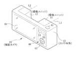
図1に示すように、本発明の複眼カメラ10(複眼撮像装置)は、被写体からの光を光電変換して撮像信号を得る撮像ユニット11(第1の撮像ユニット)、及び撮像ユニット12(第2の撮像ユニット)と、複数の撮像ユニットを同時に取り付けることができるカメラ本体13とから構成される。 As shown in FIG. 1, a compound-eye camera 10 (compound-eye imaging device) of the present invention includes an imaging unit 11 (first imaging unit) that obtains an imaging signal by photoelectrically converting light from a subject, and an imaging unit 12 (first imaging unit). 2 imaging units) and a
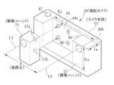
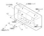
図2に示すように、撮像ユニット11のケース14は、2個の立方体を縦に連結した直方体に形成される。したがって、撮像ユニット11の前面16a、右側面16b、背面16c、左側面16dは短辺Laに対して2倍の長さの長辺Lbを有する長方形となっており、上面16e及び底面16fは短辺Laを一辺とする正方形となっている。 As shown in FIG. 2, the
撮像ユニット11の前面16aには、撮像光学系21の対物レンズ26(図4参照)が左上隅部に近接させて配置されており、前面16aの中心に対して偏心した位置となっている。また、背面16cには、2個の凸接続部17a,17b(第1の接続部)が縦中心線上で上からLa/2、3La/2の位置に立方体状に突出して形成される。この凸接続部17a,17bの上面には、接続端子及び検出端子が形成されている。接続端子は、画像データや各種指令の信号用の端子である。また、検出端子は、撮像ユニットの取り付け姿勢(縦姿勢又は横姿勢)、カメラ本体への取り付け位置、光軸の位置から分類される撮像ユニットの型(例えば、撮像ユニット11又は撮像ユニット12)を確認する信号用の端子であり、例えば、接続端子の片側にそれぞれ配置される。 On the
凸接続部17a,17bは、カメラ本体13の凹接続部46(後述する)に嵌合して、カメラ本体13に撮像ユニットが取り付けられる。そして、撮像ユニットは凹接続部46を介してカメラ本体13と電気的に結合され、各種信号の送受信が行われる。なお、凸接続部17a,17bには図示しないクリック係止機構が設けられている。このクリック係止機構は凸接続部17a,17bが凹接続部46に接続された状態で凹接続部46の溝部に突出し、撮像ユニットがカメラ本体13から脱落することを防ぐ。なお、このようなクリック係止機構に替えて、又はこのようなクリック係止機構に加えてカメラ本体13側に脱落防止突起や蓋などからなる脱落防止部材を設けても良い。なお、撮像ユニット12の凸接続部17a,17bも上述の撮像ユニット11の凸接続部17a,17bと略同様に構成されるから、図及び説明を省略する。 The
図3及び図4に示すように、撮像ユニット11は、前述のケース14と、このケース14内に収納される撮像光学系21及び光学系駆動部22とから構成されている。 As shown in FIGS. 3 and 4, the imaging unit 11 includes the above-described
撮像光学系21は、例えば、対物レンズ26、プリズム27、ズームレンズ28、絞り29、フォーカスレンズ31、CCD32(撮像素子)などから構成される。 The imaging
対物レンズ26は、ユニット開口33から入射する被写体光をプリズム27へと導く。プリズム27は、三角柱状に形成され、光軸L1に沿って入射する光を屈曲させ、このプリズム27の下方に設けられたCCD32の受光面へ導く。 The
ズームレンズ29は、プリズム27とCCD32との間でプリズム27に近接して設けられる。このズームレンズ28は、プリズム27によって屈曲した光軸L1に沿って上下に移動自在に設けられ、撮像する倍率を変化させる。絞り29は、ズームレンズ28の下方に設けられ、後述するレリーズボタン47が半押し操作されると作動し、絞り開口34の面積を変化させ、撮影光量を調節する。 The
フォーカスレンズ31は、絞り29とCCD32との間に、プリズム27によって屈曲した光軸L1に沿って上下に移動自在に設けられる。フォーカスレンズ31は、ズームレンズ29の上下移動による撮像倍率の変化や、レリーズボタン47の半押し操作にともなって作動し、焦点調節を行う。CCD32は、受光面で被写体光を光電変換し、アナログの撮像信号を凸接続部16bからカメラ本体13に出力する。 The
光学系駆動部22は、ズームモータ36、ズームリードスクリュ37、ズームキャリッジ38、絞り用モータ39、フォーカスモータ41、フォーカスリードスクリュ42、フォーカスキャリッジ43から構成される。 The optical
ズームリードスクリュ37及びフォーカスリードスクリュ42は、プリズム27によって屈曲した光軸L1に平行に配置される。ズームリードスクリュ37にはズームキャリッジ38の雌ネジ部が螺合されている。また、ズームリードスクリュ37はズームモータ36により回転される。ズームキャリッジ38は回転することがないように且つ光軸L1方向に移動自在に取り付けられており、ズームリードスクリュ37が回転することにより、ズームキャリッジ38が光軸L1方向で移動する。ズームキャリッジ38にはズームレンズ28が保持されており、ズームレンズ22の位置が変更されることによって、ズーム倍率が変更される。 The
同様にして、フォーカスリードスクリュ42にはフォーカスキャリッジ43の雌ネジ部が螺合されており、フォーカスリードスクリュ42はフォーカスモータ41により回転される。フォーカスキャリッジ43は回転することがないように且つ光軸L1方向に移動自在に取り付けられており、フォーカスリードスクリュ42が回転することにより、フォーカスキャリッジ43が光軸L1方向で移動する。フォーカスキャリッジ43にはフォーカスレンズ31が保持されており、フォーカスレンズ31の位置が変更されることによって、ピント調節が行われる。 Similarly, the female screw portion of the
ズームモータ36は、プリズム27によって屈曲した光軸L1に平行に配設されるズームリードスクリュ37を回転させることでズームキャリッジ38を光軸L1に沿って上下に移動させる。これにより、ズームキャリッジ38に保持されるズームレンズ29は、光軸L1に沿って移動される。 The
絞り用モータ39は、撮像に適当な光量の被写体光がCCD32の受光面に到達するように、絞り開口34の面積を変化させる。フォーカスモータ41は、プリズム27によって屈曲した光軸L1に平行に配設されるフォーカスリードスクリュ42を回転させることでフォーカスキャリッジ43を光軸L1に沿って上下に移動させる。これにより、フォーカスキャリッジ43に保持されるフォーカスレンズ31は、光軸L1に沿って移動される。 The
ケース14内で左側に撮像光学系21が配置され、右側に光学系駆動部22が配置されることにより、撮像光学系21の対物レンズ26はケース14の前面16aの中心に対して左側に偏心して配置される。また、撮像光学系21の対物レンズ26はケース14内の上部に配置されるため、ケース14の前面の中心に対して上側に対物レンズ26は偏心して配置される。これらの偏心配置によって、前述のように対物レンズ26はケース14の前面に対して左上隅部に配置されることになる。
Since the imaging
第2の撮像ユニット12も、第1の撮像ユニット11と同様に構成されており、前面16aに対物レンズ26が、背面16cに凸接続部17a,17bが配置されている。この第2撮像ユニット12が第1撮像ユニット11と異なっている点は、対物レンズ26が第1の撮像ユニット11とは左右対称になるように、右上隅部に形成されている点である。 The
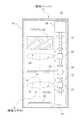
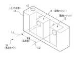
図5に示すように、カメラ本体13は中央部分に直方体状の収納凹部44を備えている。この収納凹部44は、カメラ本体13の前面44a(取付面)及び上面44bに開口し、撮像ユニットを4個並べて収納可能な大きさ(縦:2La(=Lb)、横:4La(=2Lb)、奥行き:La)になっている。 As shown in FIG. 5, the
収納凹部44の前面44aには、撮像ユニット11,12の凸接続部17a,17bが入り込むことで電気的に接続される凹接続部46(第2の接続部)が形成されている。この凹接続部46は、撮像ユニットが縦姿勢及び横姿勢の何れでも収納可能なように、縦姿勢の凸接続部17a,17b及び横姿勢の凸接続部17a,17bに対応する位置に形成されている。 A concave connection portion 46 (second connection portion) that is electrically connected when the
また、凹接続部46は撮像ユニットの凸接続部17a,17bが嵌合される形状の溝となっており、各側面には接続端子及び検出端子が形成されている。これら各側面の何れに凸接続部17a,17bの各端子が接続されるかによって、カメラ本体13は撮像ユニットの取り付け姿勢及び取り付け位置を検出する。例えば、凹接続部46の上面の端子と凸接続部17a,17bの上面の端子同士がそれぞれ結合されている場合には縦正立姿勢(縦姿勢)であり、凹接続部46の下面の端子と凸接続部17a,17bの端子とがそれぞれ結合されている場合には縦倒立姿勢(縦姿勢)であることがわかる。また、例えば、凹接続部46の右側面の端子と凸接続部17a,17bの端子同士が結合されている場合には横右姿勢(横姿勢)であり、凹接続部46の左側面の端子と凸接続部17a,17bの端子同士が結合されている場合には横左姿勢(横姿勢)であることがわかる。また、2個の凸接続部17a,17bを用いているため、これらの凸接続部17a,17bが接続される2個の凹接続部46の位置によってカメラ本体13は取り付け位置を判別する。さらに、カメラ本体13は検出端子から受ける検出信号に基づいて撮像ユニットの型、すなわち、接続されている撮像ユニットが第1の撮像ユニット11であるのか、あるいは第2の撮像ユニット12であるのかを判別する。そして、上述のように判別した撮像ユニットの型、撮像ユニットの取り付け位置及び取り付け姿勢に基づいて、カメラ本体13は接続されている撮像ユニットの光軸の位置、例えば撮像ユニットの光軸L1の位置や撮像ユニットの光軸L2の位置を判断する。 Moreover, the
凹接続部46と凸接続部17a,17bとの接続端子の接続を介して、カメラ本体13は撮像ユニット11に電力を供給する。また、この接続端子の接合を介して、カメラ本体13は撮像ユニット11を適切に動作させる信号などを送信し、撮像ユニット11からの撮像信号を受信する。例えば、ズームモータ36を動作させるズーム信号、絞り29を動作させる光量調節信号、フォーカスモータ41を動作させるフォーカス信号、CCD32を動作させるCCD駆動信号などをカメラ本体13は撮像ユニット11に送信し、撮像ユニット11を適切に駆動する。 The
基線長は、周知のように、複数の撮像ユニットを用いて撮像し、視差のある2つの画像を得るときに、対になる撮像ユニットの撮像光軸間の長さである。例えば、図5に示すように、カメラ本体13に第1の撮像ユニット11と第2の撮像ユニット12とを、収納凹部44の左端と右端にそれぞれ縦姿勢で取り付けて撮像する場合には、第1の撮像ユニット11の光軸L1と第2の撮像ユニット12の光軸L2との間の長さが基線長Rとなる。 As is well known, the base line length is a length between the imaging optical axes of a pair of imaging units when imaging is performed using a plurality of imaging units to obtain two images with parallax. For example, as shown in FIG. 5, when the first image pickup unit 11 and the second
カメラ本体13の上面44bには、後述する操作部48の一部として、複眼カメラ10によって被写体を撮像するためのレリーズボタン47が備えられる。このレリーズボタン47は、半押しと全押しの2段階に押圧操作を行うことが可能となっている。1段階目の半押し操作によって、カメラ本体13に取り付けられた撮像ユニットは自動的に焦点や撮影光量の調節を行い、2段階目の全押し操作によって実際に撮像が実行されると、被写体像が得られる。 The
図6に示すように、カメラ本体13の背面には、複眼カメラ10を操作する操作部48と表示パネル49とが備えられている。 As shown in FIG. 6, an
表示パネル49は、撮像するときにリアルタイムに解像度の低いスルー画像を表示する電子ビューファインダとして機能するとともに、メモリカードなどの記憶媒体に記憶された画像を表示するディスプレイとして機能する。また、後述する操作部48の操作により、複眼カメラ10の設定を変更するためのメニューなども表示する。 The
この表示パネル49は、液晶表示装置であるが、パララックスバリアを用いた液晶表示装置であり、表示モードとして立体表示モードと平面表示モードとを備える。立体表示モードにおいては、表示するスルー画像やメモリカードなどに記憶された画像などを立体的に認識させるように表示する。 The
具体的には、表示パネル49は、液晶表示層とともにパララックスバリア表示層を備える。表示パネル49の表示方法が立体表示モードに設定されている場合には、パララックスバリア表示層にパララックスバリアを形成し、このパララックスバリアのピッチに応じた左眼用及び右眼用の短冊状の断片画像を交互に配列した画像を液晶表示層に表示する。 Specifically, the
一方、平面表示モードにおいては、通常の液晶表示装置のように、表示する画像などを平面の画像として表示する場合には、パララックスバリア表示層にパララックスバリアを形成せず、通常の画像を液晶表示層に表示する。さらに、表示パネル49は、複数の画像を並べて表示するマルチ表示モードや、いくつかの画像を半透明にして重ねて表示する重ね表示モードなどを備える。 On the other hand, in the flat display mode, when displaying an image to be displayed as a flat image as in a normal liquid crystal display device, a normal image is not formed without forming a parallax barrier in the parallax barrier display layer. Display on the liquid crystal display layer. Furthermore, the
このような表示方法の変更は、後述する操作部48の操作し、表示パネル49の設定を変更することによって自由に切り替えられる。また、表示パネル49を電子ビューファインダとして用い、スルー画像を表示する際には立体表示を行い、メニューなどを表示する際には平面表示というように、使用条件に応じても表示パネル49の表示方法を設定される。 Such a change in the display method can be freely switched by operating the
操作部48は、前述のレリーズボタン47と、カメラ本体13の背面に配設されるメニューボタン51、マルチファンクションキー52、電源ボタン53とから構成される。 The
メニューボタン51を押圧操作することによって、表示パネル49に複眼カメラ10を操作するメニューが表示される。表示パネル49に表示されるメニューには、被写体を撮像する撮像モードの選択メニュー、表示パネル49の表示方法を指定する表示モードの選択メニュー、撮像した画像の記録方法を指定する記録モードの選択メニューなどがある。 By pressing the
撮影モードには、1つの撮像ユニットを用いて撮像する単眼撮影モード、複数の撮像ユニットを用いて撮像する複眼撮影モードがある。単眼撮影モードは、複眼カメラ10に取り付けられた撮像ユニットうちの一つを用いて1枚の被写体画像を取得する。 The photographing mode includes a monocular photographing mode in which an image is taken using one imaging unit and a compound eye photographing mode in which an image is taken using a plurality of imaging units. In the monocular imaging mode, one subject image is acquired using one of the imaging units attached to the
複眼カメラ10が備える複眼撮像モードとしては、複数の撮像ユニット用いて画像を取得する複眼モードに加え、パノラマモード、パンフォーカスモード、ダイナミックレンジ拡大モード、特殊撮影モード、マルチズームモード、連写モードなど、取得した複数の画像に特殊な加工などを施す特殊撮影モードを備える。 Compound eye imaging modes included in the
複眼モードでは、撮像に用いる各々の撮像ユニットごとの撮影条件を一致させて同時撮影を行い、視差のある複数の画像を得る。これらの画像はメモリカードなどの記憶媒体に関連付けられて記憶され、後に画像処理することによって画像の3次元データを取得する場合や、特殊な画像を合成する場合などに用いられる。 In the compound eye mode, simultaneous shooting is performed by matching the shooting conditions for each imaging unit used for imaging, and a plurality of images with parallax are obtained. These images are stored in association with a storage medium such as a memory card, and are used when image three-dimensional data is acquired later by image processing or when a special image is synthesized.
パノラマモードでは、撮像に用いる各々の撮像ユニットごとの撮影条件を一致させて同時撮影を行い、撮像範囲が一部重なっている2つの画像を得る。これらの画像のうち一方から重複する撮影範囲を除き、他方の画像につなぎ合わせることで、一つの撮像ユニットで撮像した画像よりも広い範囲を写したパノラマ画像を合成する。 In the panorama mode, the simultaneous shooting is performed by matching the shooting conditions for each of the imaging units used for imaging, and two images whose imaging ranges partially overlap are obtained. A panoramic image in which a wider range than the image captured by one imaging unit is synthesized by excluding the overlapping imaging range from one of these images and joining the other images.
パンフォーカスモードでは、撮像に用いる各々の撮像ユニットごとに焦点位置を意図的にずらして同時撮影を行い、得られた複数の画像から合焦範囲の広い1枚の画像を合成する。 In the pan focus mode, simultaneous imaging is performed by intentionally shifting the focus position for each imaging unit used for imaging, and one image with a wide focusing range is synthesized from the obtained plurality of images.
ダイナミックレンジ拡大モードでは、撮像に用いる各々の撮像ユニットごとに露出条件を変えて同時撮影を行い、得られた複数の画像からダイナミックレンジの広い1枚の画像を合成する。 In the dynamic range expansion mode, simultaneous imaging is performed by changing the exposure condition for each imaging unit used for imaging, and one image having a wide dynamic range is synthesized from the obtained plurality of images.
特殊撮影モードでは、撮像に用いる撮像ユニットの撮影条件を一致させて同時撮影を行い、視差のある複数の画像を得ると、自動的に3次元データを抽出し、この3次元データに基づいて、いわゆる被写界深度の浅い1枚の画像を合成する。すなわち、背景をぼかし、主要被写体が際立つ1枚の画像を合成する。 In the special shooting mode, the shooting conditions of the imaging units used for shooting are made to coincide, and when a plurality of images with parallax are obtained, three-dimensional data is automatically extracted, and based on this three-dimensional data, One image with a shallow depth of field is synthesized. That is, the background is blurred and one image in which the main subject stands out is synthesized.
マルチズームモードでは、撮像に用いる撮像ユニットごとに画角を変えて同時撮影を行い、得られた複数の画像から主要被写体が高解像度で写された1枚の画像を合成する。 In the multi-zoom mode, simultaneous shooting is performed by changing the angle of view for each imaging unit used for imaging, and a single image in which the main subject is captured at a high resolution is synthesized from a plurality of obtained images.
連写モードでは、撮像に用いる撮像ユニットをそれぞれ所定の時間間隔で駆動し、連続した画像を得る。 In the continuous shooting mode, each imaging unit used for imaging is driven at predetermined time intervals to obtain continuous images.
マルチファンクションキー52は、複眼カメラ10の設定時には、表示パネル49に表示されるメニューの各項目にカーソルを移動する十字キーとして機能し、中央部を押圧操作することによって項目を選択するいわゆる決定キーとしても機能する。また、撮像時においては、このマルチファンクションキー52は、撮像範囲を拡大又は縮小するいわゆるズームキーとしても機能する。さらに、メモリカード54などから読み出された画像を表示パネル49に表示する場合には、コマ送りキーなどとしても機能する。 The multi-function key 52 functions as a cross key for moving the cursor to each item of the menu displayed on the
電源ボタン53は、長押し操作することにより複眼カメラ10の電源をオン又はオフにする。なお、複眼カメラ10は、図示しない内臓バッテリなどによって電力を供給される。 The power button 53 turns the power of the
また、カメラ本体13の側面には、メモリカードスロット(図示しない)、外部機器と複眼カメラ10を接続する複数の外部接続端子(図示しない)などを備える。撮像した画像などを記憶し、複眼カメラ10の記憶装置として機能するメモリカード54を挿入する。また、外部接続端子は、外部電源やコンピュータなどと複眼カメラ10とを接続する。 Further, the side surface of the
図7に示すように、複眼カメラ10は、撮像ユニット駆動部71(ユニット制御部)、DSP(Digital Signal Proseccor)72、CPU73、表示画像処理部74、SDRAM76、EEPROM77などから構成される。 As shown in FIG. 7, the compound-
撮像ユニット駆動部71は、一つの撮像ユニット検出部78と、CCDドライバ81、モータドライバ82、相関二重サンプリング回路(CDS)83、信号増幅器(AMP)84、A/D変換機(A/D)86をカメラ本体13に取り付けられるそれぞれの撮像ユニットごとに備える。したがって、最大で4個の撮像ユニットを同時に取り付けることができる複眼カメラ10は、CCDドライバ81、モータドライバ82、CDS83、AMP84、A/D86を1つの組として、4つの組を備える。これらにより、複数の撮像ユニットを同時に駆動し、同時撮影などを行う。 The imaging
撮像ユニット検出部78は、撮像ユニットの取り付け位置及び取り付け姿勢を検出する。具体的には、凹接続部46のいずれの側面の検出端子が撮像ユニットの凸接続部17a,17bと接続されているかを判断する。また、凹接続部46と凸接続部17a,17bの検出端子同士の接合を介して、検出信号を受ける。この検出信号には、接続されている撮像ユニットの型を判別するためのユニットタイプ信号や、接続されている撮像ユニットのID信号などがある。そして、これらに基づいて、撮像ユニット検出部78は同一の撮像ユニットに属する凸接続部を判別し、さらには、同一の撮像ユニットに属する凸接続部17a,17bの接続される位置から接続さている撮像ユニットの取り付け位置及び取り付け姿勢を検出する。さらに、撮像ユニット検出部87は、検出した撮像ユニットの型、取り付け位置及び取り付け姿勢から、取り付けられた撮像ユニットの光軸の位置を判断する。なお、撮像ユニットの型、個数、取り付け位置及び取り付け姿勢、光軸の位置などの情報は、SDRAM76に記憶される。 The imaging
CCDドライバ81は、撮像ユニット検出部78によって接続の検出された撮像ユニットのCCDを駆動する。このCCDドライバ81は、CPU73によって制御され、凹接続部46と凸接続部17bとを介して、目的のCCD32を駆動する。また、複数の撮像ユニットがカメラ本体13に接続されている場合には、撮像ユニット駆動部71が備える4つのCCDドライバ81のうち、何れのCCDドライバ81が何れの撮像ユニットのCCDを駆動するかは、CPU73によって割り当てられる。 The
モータドライバ82は、ズームモータ36、絞り用モータ39、フォーカスモータ41を駆動する。このモータドライバ82によるモータの駆動は、CPU73によって制御される。例えば、各種モータを駆動する順序や駆動量などはCPU73によって制御される。 The
CDS83は、撮像時などにCCD32から出力されるアナログの撮像信号を受けて、ノイズを除去し、AMP84へ出力する。AMP84は、CDS83によってノイズを除去されたアナログの撮像信号を増幅し、A/D86へと出力する。A/D86は、AMP84によって増幅されたアナログの撮像信号をデジタルな画像データに変換し、DSP72へ入力する。A/D86が出力するデジタルな画像データは、CCD32の各セルの蓄積電荷量に正確に対応したR,G,Bの画像データである。 The CDS 83 receives an analog imaging signal output from the
DSP72は、画像入力コントローラ87、画質補正処理回路88、YC変換処理回路89、圧縮伸張処理回路91などから構成され、A/D86から入力されるRGBの画像データをSDRAM76に一時的に記憶した後に各種画像処理を施す。 The
また、DSP72は、データバス92を介して、AE/AWB検出回路(図示せず)とAF検出回路(図示せず)とに接続されている。AE/AWB検出回路は、撮像に用いる撮像ユニットの露出量、すなわち電子シャッタのシャッタ速度と絞り開口34の面積が撮像に適切か否かを、撮像に用いる撮像ユニットそれぞれについて検出する。AF検出回路は、撮像に用いる撮像ユニットそれぞれについて、焦点調節が撮像に適切か否かを検出する。 The
画像入力コントローラ87は、A/D86から入力される画像データをバッファリングし、データバス92を介して接続されたSDRAM76に記憶させる。画質補正処理回路88は、画像入力コントローラ87によってSDRAM76に書き込まれた画像データを読み出し、階調変換、ホワイトバランス補正、γ補正処理などの画像処理を施し、この画像データを再度SDRAM76に記憶させる。YC変換処理回路89は、画質補正処理回路88によって各種の画像処理を施された画像データをSDRAM76から読み出し、輝度信号Yと色差信号Cr,Cbとに変換する。圧縮伸張処理回路91は、YC変換された画像データを所定の方式に、例えば、JPEGやTIFFといったファイル形式に圧縮して出力する。そして、圧縮された画像データは、メディアコントローラ93を介してメモリカード54に記憶される。 The image input controller 87 buffers the image data input from the A /
撮像ユニット駆動部71は、レリーズボタン47が押圧操作されると、接続された撮像ユニットから画素数の大きな本画像データを取得する。一方で、表示パネル49を電子ビューファインダとして用いている間、表示パネル49へスルー表示するための画素数の小さなスルー画像データを取得する。このスルー画像データの取得は、毎秒30フレームのフレームレートで行われる。このスルー画像データは、本画像データと同様にして、DSP72による各種画像処理を施された後に、SDRAM76へ一時的に記憶される。一方、本画像データは、上述の各種画像処理が施された後に、メモリカード54に記憶されるのに対して、スルー画像データは表示画像処理部74に読み出されて、スルー表示に適切な画像処理を施された後に、エンコーダ94によってアナログのコンポジット信号に変換され、表示パネル49にビデオ出力される。SDRAM76内には、スルー画像データを格納するVRAM領域が確保されており、VRAM領域内のスルー画像は、前述のフレームレートに合わせて随時更新されて表示パネル49に出力される。 When the
表示画像処理部74は、SDRAM76やメモリカード54などに記憶された画像データを、予め設定された表示パネル49の表示方法に応じて画像処理し、エンコーダ94を介して表示パネル49に画像などを表示させる。 The display
表示パネル49の表示方法の設定が立体表示モードである場合には、表示画像処理部74は、パララックスバリア表示層にパララックスバリアを形成するとともに、SDRAM76やメモリカード54から立体表示する画像データを読み出し、パララックスバリアのピッチに応じた左眼用及び右眼用の短冊状の断片画像を交互に配列した1つの立体表示用画像データを合成する。この立体表示用画像データは、エンコーダ94を介して表示パネル49の液晶表示層に表示される。 When the setting of the display method of the
一方、表示パネル49の表示方法の設定が平面表示モードである場合には、表示画像処理部74は、パララックスバリア表示層にパララックスバリアを形成せず、SDRAM76やメモリカード54から表示パネル49に平面表示する画像データを読み出し、エンコーダ94を介して表示パネル49の液晶表示層に表示させる。 On the other hand, when the setting of the display method of the
また、表示パネル49の表示方法の設定がマルチ表示モードである場合には、表示画像処理部74は、予め設定された数の複数の画像データをSDRAM76やメモリカード54から読み出し、これらの画像データから、複数の画像を縮小して配列した1枚のマルチ表示画像を合成する。このマルチ表示画像は、エンコーダ94を介して表示パネル49の液晶表示層に表示される。 When the setting of the display method of the
さらに、表示パネル49の表示方法の設定が重ね表示モードである場合には、表示画像処理部74は、予め設定された数の複数の画像データをSDRAM76やメモリカード54から読み出し、これらの画像データを半透明化し、重ね合わせた1枚の重ね画像データを合成する。そして、この重ね画像データは、エンコーダ94を介して表示パネル49の液晶表示層に表示される。 Further, when the setting of the display method of the
また、撮像時などにスルー画像を表示し、表示パネル49を電子ビューファインダとして用いる場合には、表示画像処理部74は、SDRAM76のVRAM領域からスルー画像データを、更新されるごとに随時読み出す。そして、上述のように予め設定された表示パネル49の各種表示方法に応じた画像処理を行い、エンコーダ94を介して表示パネル49の液晶表示層にスルー画像を表示させる。 Further, when a through image is displayed at the time of imaging or the like and the
CPU73は、複眼カメラ10を制御するための制御用プログラムをEEPROM77から読み出し、実行する。そして、操作部48の操作に応じて、上述のように複眼カメラ10の各部の動作を統括的に制御する。さらに、例えば、CPU73は、AE/AWB検出回路やAF検出回路の検出結果に基づいて、撮像ユニット駆動部71の各部を駆動し、複眼カメラ10に接続された撮像ユニットをそれぞれ制御する。また、例えば、CPU73は、撮像ユニット検出部78の検出結果に基づいて視差のある2つの画像を撮像する撮像ユニットの対を判断し、撮像するときの基線長を判断する。そして、撮像して得られた画像を互いに関連付ける情報とともに、撮像条件などの情報、例えば基線長などを画像とともにSDRAM76に保存する。 The
また、CPU73は、撮像ユニット検出部78による検出結果に基づいて、カメラ本体13に取り付けられた撮像ユニットの個数と取り付け位置や取り付け姿勢などの状態を判断し、撮像時に動作させる順序や、電子ビューファインダとして用いる表示パネル49に標準で表示するスルー画像データを取得する撮像ユニットなどを決定し、上述のように制御する。 Further, the
SDRAM76は、作業用のメモリであり、画像データや設定の情報が一時的に記憶されるとともに、CPU73によって実行される制御用プログラムがロードされる。EEPROM77には、CPU73によって実行される複眼カメラ10の各部を制御する制御用プログラムや設定情報などが記憶されている。 The
以上のように構成される複眼カメラ10の作用について説明する。複眼カメラ10を、一般的なデジタルカメラと同様に単眼のデジタルカメラとして用いる場合には、複眼カメラ10に1つの撮像ユニットを取り付けて撮像を行うか、又は、複数取り付けられた撮像ユニットの任意の一つを用いて撮像を行う。このとき、撮像ユニットの取り付け位置や取り付け姿勢は任意である。すなわち、撮像ユニットを縦姿勢又は横姿勢で、任意の位置に取り付けて撮像することができる。 The operation of the
一方、複眼カメラ10を用いて視差のある1対の画像を撮像する場合や、同時に撮像した複数の画像から特殊な画像を合成する撮像モードで撮像する場合には、カメラ本体13に2個以上の撮像ユニットを取り付けて撮像を行う。 On the other hand, when capturing a pair of images with parallax using the
このように、2個の撮像ユニットをカメラ本体13に取り付けて撮像するときには、同じタイプの撮像ユニットを2個組み合わせて用いる場合と、異なるタイプの撮像ユニットを2個組み合わせて用いる場合がある。 As described above, when two image pickup units are attached to the
なお、前述のように撮像ユニットの前面をなす長方形の短辺の長さはLa、長辺の長さはLb=2Laであり、以下では撮像ユニットの前面をなす長方形の各辺に対して、撮像ユニットの光軸が最も近い長辺までの距離をLp、撮像ユニットの光軸が最も近い短辺までの距離をLqとする。 As described above, the length of the short side of the rectangle forming the front surface of the imaging unit is La, and the length of the long side is Lb = 2La. In the following, for each side of the rectangle forming the front surface of the imaging unit, The distance to the long side where the optical axis of the imaging unit is closest is Lp, and the distance to the short side where the optical axis of the imaging unit is closest is Lq.
まず、2個の同じタイプの撮像ユニットを組み合わせて用いる場合には、例えば、撮像ユニット11とともに、撮像ユニット11と光軸の配置などが全く同様に構成される撮像ユニット96の2個を用いる。そして、例えば、図8に示すように、撮像ユニット11の光軸L1と撮像ユニット96の光軸L3とが最も離れるように、撮像ユニット11と撮像ユニット96をそれぞれ縦姿勢でカメラ本体13に取り付ける。すなわち、撮像ユニット11と撮像ユニット96とを撮像ユニット2個分の間隔をあけて、縦姿勢で取り付ける。 First, when two imaging units of the same type are used in combination, for example, two
このとき、光軸L1と光軸L3との間の長さである基線長R2は3Laであり、同じタイプの2個の撮像ユニットを組み合わせて用いる場合の撮像ユニットの配置の中で最も長い基線長であるから、比較的遠方に被写体がある場合や、遠景を撮像する場合に適する撮像ユニットの配置である。また、撮像ユニット11の光軸L1と撮像ユニット96の光軸L3は、カメラ本体13に対して垂直方向には同じ高さにあり、水平方向に基線長R2だけ離れているから、撮像ユニット11と撮像ユニット96とを用いて同時に同じ被写体を撮像すると、水平方向に視差のある1対の画像を得ることができる。 At this time, the base length R2 which is the length between the optical axis L1 and the optical axis L3 is 3La, and is the longest base line in the arrangement of the imaging units when two imaging units of the same type are used in combination. Since it is long, it is an arrangement of an imaging unit suitable for a case where a subject is located relatively far away or when a far view is imaged. Further, the optical axis L1 of the imaging unit 11 and the optical axis L3 of the
同様に、2個の同じタイプの撮像ユニット、すなわち撮像ユニット11と撮像ユニット96とを組み合わせて用いる場合に、例えば、図9に示すように、撮像ユニット11と撮像ユニット96とを縦姿勢で、撮像ユニット1個分の間隔をあけて取り付ける。 Similarly, when two imaging units of the same type, that is, the imaging unit 11 and the
このとき、光軸L1と光軸L3との間の長さである基線長R5の長さは2Laであり、上述の基線長R2と比較して、Laだけ短くなる。したがって、基線長がR2となる配置に撮像ユニット11と撮像ユニット96とを取り付ける場合(図8)と比較して、比較的近い位置に被写体がある場合や、中距離程度の風景などを撮像する場合に適する撮像ユニットの配置である。なお、図9においては、図8と比較して、撮像ユニット11を撮像ユニット1個分だけ撮像ユニット96に近づけて取り付けるが、撮像ユニット96を撮像ユニット1個分だけ撮像ユニット11に近づけて配置する場合も、当然ながら光軸L1と光軸L3との間の長さは、基線長R5となる。したがって、光軸L1と光軸L3との間の長さが基線長R5となる撮像ユニット11及び撮像ユニット96の取り付け位置は、2通りの配置何れかが任意に選択される。 At this time, the length of the base line length R5, which is the length between the optical axis L1 and the optical axis L3, is 2La, and is shorter by La than the above-described base line length R2. Therefore, as compared with the case where the imaging unit 11 and the
さらに、上述のように、2個の同じタイプの撮像ユニット、すなわち撮像ユニット11と撮像ユニット96とを組み合わせて用いる場合に、例えば、図10に示すように、撮像ユニット11と撮像ユニット96とを縦姿勢で、間隔をあけず、隣接して取り付ける。 Furthermore, as described above, when two imaging units of the same type, that is, the imaging unit 11 and the
このとき、光軸L1と光軸L3との間の長さである基線長R8はLaであり、2個の同じタイプの撮像ユニットを縦姿勢で組み合わせて用いる場合の中で、最も短い基線長となる。したがって、比較的近い位置に被写体がある場合や、近距離の風景などを撮像する場合に適する撮像ユニットの配置である。なお、このように撮像ユニット11と撮像ユニット96とを、縦姿勢で隣接させてカメラ本体13に取り付ける位置は3通りあるが、何れも基線長はR8となるから、任意に選択される。 At this time, the baseline length R8, which is the length between the optical axis L1 and the optical axis L3, is La, and is the shortest baseline length in the case of using two imaging units of the same type combined in a vertical posture. It becomes. Therefore, the arrangement of the imaging units is suitable when there is a subject at a relatively close position or when imaging a short distance landscape or the like. There are three positions where the image pickup unit 11 and the
次に、異なるタイプの2個の撮像ユニットを組み合わせて用いる場合には、例えば、撮像ユニット11と撮像ユニット12を組み合わせて用いる。撮像ユニット12は、前述のように、撮像光学系21と光学系駆動部22との配置が撮像ユニット11と逆になっている撮像ユニットであり、回転しても撮像ユニット11とは重ならず、撮像ユニット11とは異なるから、タイプの異なる撮像ユニット11と撮像ユニット12とを組み合わせて用いることで、さらに多様な基線長の長さを任意に選択して撮像することができる。 Next, when two different types of imaging units are used in combination, for example, the imaging unit 11 and the
例えば、図11に示すように、光軸L1と光軸L2とが最も離れるように、撮像ユニット11と撮像ユニット12とをそれぞれ縦姿勢で取り付ける。すなわち、撮像ユニット11と撮像ユニット12とを撮像ユニット2個分の間隔をあけて、縦姿勢で、カメラ本体13の上方に撮像光学系21の対物レンズ26が位置するように、それぞれ取り付ける。 For example, as illustrated in FIG. 11, the imaging unit 11 and the
このとき、光軸L1と光軸L2との間の長さである基線長R1は4La−2Lpであり、前述の基線長R2よりも長く、2個の撮像ユニットを組み合わせて撮像を行う場合の中で最も長い基線長である。したがって、光軸L1と光軸L2との間の長さである基線長がR1となる撮像ユニットの配置と組み合わせは、カメラ本体13に取り付ける撮像ユニットの配置及び組み合わせのなかで、被写体が最も遠くにある場合や、最も遠景を撮像する場合に適する。 At this time, the baseline length R1 which is the length between the optical axis L1 and the optical axis L2 is 4La-2Lp, which is longer than the baseline length R2 described above, and when imaging is performed by combining two imaging units. It is the longest baseline length among them. Accordingly, the arrangement and combination of the imaging units in which the base line length R1 between the optical axis L1 and the optical axis L2 is R1 is the farthest subject among the arrangements and combinations of the imaging units attached to the
また、図12に示すように、光軸L1と光軸L2との間の長さが基線長R1となる撮像ユニット11と撮像ユニット12の配置(図11)から、撮像ユニット11と撮像ユニット12の位置を入れ替えて配置すると、基線長R3は2La+2Lpとなる。この基線長R3の長さは、基線長R1,R2よりも短く、基線長R5よりも長い。したがって、光軸L1と光軸L2との間の長さが基線長R3となる撮像ユニットの配置は、光軸L1と光軸L2との間の長さが基線長R1となる撮像ユニットの配置と比較して、より近くに被写体がある場合や、より近景を撮像する場合に適する。 Also, as shown in FIG. 12, from the arrangement (FIG. 11) of the imaging unit 11 and the
また、図13に示すように、撮像ユニット1個分の間隔をあけ、光軸L1と光軸L2との距離ができるだけ離れるように、撮像ユニット11と撮像ユニット12とを縦姿勢で取り付けると、基線長R4は3La−2Lpとなる。この基線長R4の長さは、基線長R3よりも短い。したがって、光軸L1と光軸L2との間の長さが基線長R4となる撮像ユニットの配置は、光軸L1と光軸L2との間の長さが基線長R3となる撮像ユニットの配置と比較して、さらに近くに被写体がある場合や、さらに近景を撮像する場合に適する。 Moreover, as shown in FIG. 13, when the imaging unit 11 and the
さらに、図14に示すように、撮像ユニット1個分の間隔をあけ、光軸L1と光軸L2との距離ができるだけ近くなるように、撮像ユニット11と撮像ユニット12とを縦姿勢で取り付けると、基線長R6はLa+2Lpとなる。この基線長R6の長さは、基線長R4よりも短い。したがって、光軸L1と光軸L2との間の長さが基線長R6となる撮像ユニットの配置は、光軸L1と光軸L2との間の長さが基線長R4となる撮像ユニットの配置と比較して、さらに近くに被写体がある場合や、さらに近景を撮像する場合に適する。 Furthermore, as shown in FIG. 14, when the imaging unit 11 and the
同様にして、図15に示すように、撮像ユニット11と撮像ユニット12とを隣接させて、光軸L1と光軸L2との距離ができるだけ離れるように縦姿勢で取り付けると、基線長R7の長さは2La−2Lpとなる。この基線長R7の長さは、基線長R6よりも短い。したがって、光軸L1と光軸L2との間の長さが基線長R7となる撮像ユニットの配置は、光軸L1と光軸L2との間の長さが基線長R6となる撮像ユニットの配置と比較して、より近くに被写体がある場合や、より近景を撮像する場合に適する。 Similarly, as shown in FIG. 15, when the imaging unit 11 and the
さらに、同様にして、図16に示すように、撮像ユニット11と撮像ユニット12とを隣接させて、光軸L1と光軸L2との距離ができるだけ近くなるように取り付けると、基線長R9の長さは2Lpとなる。この基線長R9の長さは、基線長R7よりも短く、2個の撮像ユニットを組み合わせて用いる場合の基線長の中で最も短い。したがって、光軸L1と光軸L2との距離が基線長R9となる撮像ユニットの配置は、2個の撮像ユニットを縦姿勢で取り付ける組み合わせのうち、最も近くに被写体がある場合や、最も近景を撮像する場合に適する。 Further, similarly, as shown in FIG. 16, when the imaging unit 11 and the
以上のように、複眼カメラ10は、2個の撮像ユニットのタイプ、取り付け位置及び取り付け姿勢の組み合わせを自在に変更することができるから、撮像する被写体までの距離に応じて、撮像に適切な基線長を自在に選択することができる。 As described above, since the compound-
撮像する被写体までの距離に応じて自在に選択できる基線長は、基線長R1,R2,R3,R4,R5,R6,R7,R8,R9である。Lp<La/4を満たす撮像ユニットを用いる場合、これらの基線長の長さは、R1>R2>R3>R4>R5>R6>R7>R8>R9であり、複眼カメラ10によって9種の基線長を自在に選択して撮像することができる。 Baseline lengths that can be freely selected according to the distance to the subject to be imaged are baseline lengths R1, R2, R3, R4, R5, R6, R7, R8, and R9. When an imaging unit satisfying Lp <La / 4 is used, the lengths of these baseline lengths are R1> R2> R3> R4> R5> R6> R7> R8> R9, and nine types of baselines are obtained by the
特にLp=La/4を満たすような撮像ユニットを用いる場合であっても、撮像する被写体までの距離に応じて自在に選択できる基線長はR1,R2,R3=R4,R5,R6=R7,R8,R9であり、これらはR1>R2>R3=R4>R5>R6=R7>R8>R9であるから、7種もの基線長を自在に選択して撮像することができる上に、R1はR9の7倍程度の長さとなるから、撮像ユニット11は多様な距離の被写体に適する基線長で撮像を行うことができる。 In particular, even when an imaging unit that satisfies Lp = La / 4 is used, the baseline lengths that can be freely selected according to the distance to the subject to be imaged are R1, R2, R3 = R4, R5, R6 = R7, R8, R9, and these are R1> R2> R3 = R4> R5> R6 = R7> R8> R9, so that as many as seven types of baseline lengths can be freely selected and imaged. Since the length is about seven times that of R9, the imaging unit 11 can perform imaging with a baseline length suitable for subjects at various distances.
さらには、距離Lpがそれぞれ異なるように撮像ユニット11と撮像ユニット12とを作製すれば、撮像する被写体までの距離に応じて、さらに多様な基線長の長さから、細かく選択することができる。 Furthermore, if the imaging unit 11 and the
また、上述の実施形態においては、撮像ユニット11,12の撮像光学系21にプリズムを用いてそれぞれの光軸を屈曲させる屈曲光学系を用いるから、撮像ユニットの厚みを軽減することができる。したがって、屈曲光学系を用いる撮像ユニット用いることで、複眼カメラ10の厚みを軽減することができ、複眼カメラ10の携帯性を向上させることができる。 In the above-described embodiment, since the bending optical system that bends each optical axis using a prism is used for the imaging
上記実施形態においては、2つの撮像ユニットを縦姿勢で組み合わせて用いるが、これに限らず、2つの撮像ユニットを横姿勢に組み合わせて配置してもよい。 In the above-described embodiment, two image pickup units are used in combination in a vertical posture. However, the present invention is not limited to this, and two image pickup units may be arranged in a horizontal posture.
例えば、図17に示すように、撮像ユニット11と撮像ユニット12とを横姿勢に組み合わせて用い、撮像ユニット11の光軸L1と撮像ユニット12の光軸L2との間の長さができるだけ遠くなるようにそれぞれ取り付ける。このとき光軸L1と光軸L2との間の長さは、基線長R10となる。この基線長R10の長さは、4La−Lqであり、Lp≠Lqの場合には、前述の基線長R1〜R9の何れとも異なるから、さらに基線長の選択の自由度が増す。 For example, as shown in FIG. 17, the imaging unit 11 and the
同様にして、例えば、図18に示すように、撮像ユニット11と撮像ユニット12とを横向きの状態で組み合わせて用い、光軸L1と光軸L2との間の長さができるだけ短くなるようにそれぞれ取り付ける。このとき光軸L1と光軸L2との間の長さは、基線長R11となる。この基線長R11の長さは、2Lqであり、Lp≠Lqの場合には、前述の基線長R1〜R9及び基線長R10の何れとも異なるから、さらに基線長の選択の自由度が増す。 Similarly, for example, as shown in FIG. 18, the image pickup unit 11 and the
さらに、上記実施形態においては、2つの撮像ユニットを組み合わせて用いるが、これに限らず、4個の撮像ユニットを組み合わせて用いてもよい。例えば、図19に示すように、4個の撮像ユニット、すなわち撮像ユニット11,12,96と、撮像ユニット12と光軸の配置などが全く同様に構成される撮像ユニット97とを組み合わせて用いる。 Furthermore, in the above-described embodiment, two imaging units are used in combination. However, the present invention is not limited to this, and four imaging units may be used in combination. For example, as shown in FIG. 19, four image pickup units, that is,
そして、光軸L1と光軸L2との間の長さが最も遠くなるように撮像ユニット11と撮像ユニット12とを横姿勢に並べて取り付け、かつ、撮像ユニット96の光軸L3と撮像ユニット97の光軸L4との間の長さが最も遠くなるように、横姿勢に撮像ユニット96を撮像ユニット12の下方に取り付け、撮像ユニット97を撮像ユニット11の下方に取り付ける。 Then, the imaging unit 11 and the
このとき、撮像ユニット11の光軸L1と撮像ユニット12の光軸L2との間の長さは、基線長R10となり、撮像ユニット11によって撮像される画像と撮像ユニット12によって撮像される画像とは、互いに水平方向に視差のある画像となる。また、同様に、撮像ユニット96の光軸L3と撮像ユニット97の光軸L4との間の長さは、基線長R10となり、撮像ユニット96によって撮像される画像と撮像ユニット97によって撮像される画像とは、互いに水平方向に視差のある画像となる。 At this time, the length between the optical axis L1 of the imaging unit 11 and the optical axis L2 of the
一方、撮像ユニット11の光軸L1と撮像ユニット97の光軸L4との間の長さは、基線長R7となり、撮像ユニット11によって撮像される画像と撮像ユニット97によって撮像される画像とは、カメラ本体13に対して互いに縦方向に視差のある画像となる。同様にして、撮像ユニット12の光軸L2と撮像ユニット96の光軸L3との間の長さは、基線長R7となり、撮像ユニット12によって撮像される画像と撮像ユニット97によって撮像される画像とは、カメラ本体13に対して互いに縦方向に視差のある画像となる。 On the other hand, the length between the optical axis L1 of the imaging unit 11 and the optical axis L4 of the
基線長R10の長さは、2個の撮像ユニットを横姿勢で、横に並べてカメラ本体13に取り付ける場合の中で最も長い。さらに、基線長R7は、2個の撮像ユニットを横姿勢で、縦に並べてカメラ本体13に取り付ける場合の中で最も長い。したがって、上述のように4個の撮像ユニットの配置は、遠方に被写体がある場合や、遠景を撮像する場合に適する撮像ユニットの配置である。 The length of the base line length R10 is the longest in the case where two image pickup units are mounted in the
また、図20に示すように、4個の撮像ユニット11,12,96,97を組み合わせて用い、光軸L1と光軸L2との間の長さが最も短くなるように撮像ユニット11と撮像ユニット12とを横姿勢で横に並べて取り付ける。さらに、光軸L3と光軸L4との間の長さが最も短くなるように、横姿勢で撮像ユニット97を撮像ユニット11の下方に取り付け、横姿勢で撮像ユニット96を撮像ユニット12の下方に取り付ける。 In addition, as shown in FIG. 20, the four
このとき、光軸L1と光軸L2との間の長さは、基線長R11となり、撮像ユニット11によって撮像される画像と撮像ユニット12によって撮像される画像とは、互いに水平方向に視差のある画像となる。また、同様に、光軸L3と光軸L4との間の長さは、基線長R9となり、撮像ユニット96によって撮像される画像と撮像ユニット97によって撮像される画像とは、互いに水平方向に視差のある画像となる。 At this time, the length between the optical axis L1 and the optical axis L2 is the baseline length R11, and the image captured by the imaging unit 11 and the image captured by the
一方、撮像ユニット11の光軸L1と撮像ユニット97の光軸L4との間の長さは、基線長R9となり、撮像ユニット11によって撮像される画像と撮像ユニット97によって撮像される画像とは、カメラ本体13に対して互いに縦方向に視差のある画像となる。同様にして、撮像ユニット12の光軸L2と撮像ユニット96の光軸L3との間の長さは、基線長R9となり、撮像ユニット12によって撮像される画像と撮像ユニット97によって撮像される画像とは、カメラ本体13に対して互いに縦方向に視差のある画像となる。 On the other hand, the length between the optical axis L1 of the imaging unit 11 and the optical axis L4 of the
基線長R11の長さは、2個の撮像ユニットを横姿勢で、横に並べてカメラ本体13に取り付ける場合の中で最も短い。さらに、基線長R9は、2個の撮像ユニットを横姿勢で、縦に並べてカメラ本体13に取り付ける場合の中で最も短い。したがって、上述のような4個の撮像ユニットの配置は、複眼カメラ10の近くに被写体がある場合や、近景を撮像する場合に適する撮像ユニットの配置である。 The length of the base line length R11 is the shortest in the case where two image pickup units are mounted in the
以上のように、4個の撮像ユニットを組み合わせて、これらの撮像ユニットを横姿勢で横又は縦に並べてカメラ本体13に取り付けると、被写体までの距離に応じて撮像に適した基線長を選択することができ、水平方向に視差のある画像の対を得られると同時に、カメラ本体13に対して縦方向に視差のある画像の対をも得ることができる。 As described above, when four image pickup units are combined and these image pickup units are horizontally or vertically arranged and attached to the
水平方向に視差のある画像の対は、周知のように、パノラマ画像の合成、立体視用の画像の合成、被写体の3次元データの算出などに様々な目的で利用することができる。特に、水平方向に視差のある画像の対から3次元データを算出するときに、垂直方向に視差のある画像を併用すると、3次元データを算出するときに必要な特徴点の抽出を容易に行うことができる。例えば、水平線など画像に対して横に長い形状が写された画像では、水平方向に視差のある画像の対から特徴点を抽出することは容易でないが、垂直方向に視差のある画像を併用することで容易に特徴点を抽出することができる。 As is well known, a pair of images having parallax in the horizontal direction can be used for various purposes, for example, for synthesizing panoramic images, synthesizing stereoscopic images, and calculating three-dimensional data of a subject. In particular, when calculating three-dimensional data from a pair of images having parallax in the horizontal direction, if the image having parallax in the vertical direction is used together, feature points necessary for calculating three-dimensional data can be easily extracted. be able to. For example, in an image such as a horizontal line that has a shape that is long horizontally to the image, it is not easy to extract feature points from a pair of images with parallax in the horizontal direction, but an image with parallax in the vertical direction is also used together Thus, feature points can be easily extracted.
なお、4個の撮像ユニットを組み合わせて用いる場合に、上述のように、水平方向のみならず、カメラ本体13に対して垂直方向にも光軸が並ぶように撮像ユニットをそれぞれ取り付け、カメラ本体13に対して縦方向に視差のある画像をも得るが、これに限らず、ある基線長の2個の撮像ユニットの配置と、この基線長と長さの異なる基線長となる2個の撮像ユニットの配置とを組み合わせて、4個の撮像ユニットを組み合わせて用いてもよい。 When four image pickup units are used in combination, as described above, the image pickup units are attached so that the optical axes are aligned not only in the horizontal direction but also in the vertical direction with respect to the camera
例えば、図21に示すように、4個の撮像ユニット11,12,96,97を組み合わせて用いる。このとき、光軸L1と光軸L2との間の長さが最も長くなるように、撮像ユニット11と撮像ユニット12とを横姿勢で横に並べてカメラ本体13に取り付ける。一方、光軸L3と光軸L4との間の長さが最も短くなるように、撮像ユニット96と撮像ユニット97とを横姿勢で横に並べ、撮像ユニット11の下方に撮像ユニット97を取り付け、撮像ユニット12の下方に撮像ユニット96を取り付ける。 For example, as shown in FIG. 21, four
このとき、光軸L1と光軸L2との間の長さは、基線長R10となり、撮像ユニット11によって撮像される画像と撮像ユニット12によって撮像される画像とは、互いに水平に視差のある画像となる。また、光軸L3と光軸L4との間の長さは、基線長R11となり、撮像ユニット96によって撮像される画像と撮像ユニット97によって撮像される画像とは、互いに水平に視差のある画像となる。 At this time, the length between the optical axis L1 and the optical axis L2 is the baseline length R10, and the image captured by the imaging unit 11 and the image captured by the
一方、光軸L1と光軸L4とは、カメラ本体13に対して縦方向にずれてはいるが、垂直方向にだけずれているわけではないので、撮像ユニット11によって撮像される画像と撮像ユニット97によって撮像される画像との対は、画像の長辺又は短辺に平行な視差だけがある画像の対として単純には扱えない。これは、撮像ユニット12によって撮像される画像と撮像ユニット96によって撮像される画像との視差についても同様である。 On the other hand, the optical axis L1 and the optical axis L4 are shifted in the vertical direction with respect to the
しかしながら、上述のように4個の撮像ユニットを取り付けると、基線長R10の分だけ水平に視差のある画像の対と、基線長R11の分だけ水平に視差のある画像の対とを同時に得ることができる。したがって、被写体までの距離に応じた撮像に適切な基線長を選択するために、撮像ユニット11,12,96,97の位置や向きを組み替えることなく、遠距離及び近距離の被写体に適切な基線長の視差のある画像の対を同時に得ることができる。これにより、撮像ユニットの組み替えの煩雑さを軽減することができる。 However, when four imaging units are attached as described above, a pair of images having a parallax horizontally by the baseline length R10 and a pair of images having a parallax horizontally by the baseline length R11 can be simultaneously obtained. Can do. Therefore, in order to select an appropriate baseline length for imaging according to the distance to the subject, the baseline suitable for a subject at a long distance and a short distance without changing the position and orientation of the
上述の実施形態では、4個の撮像ユニットを組み合わせて用いる場合に、全ての撮像ユニットを横姿勢でカメラ本体13に取り付けて用いるが、これに限らず、4個の撮像ユニットのうちいくつかを縦姿勢でカメラ本体13に取り付けて複眼カメラ10を用いてもよい。 In the above-described embodiment, when four imaging units are used in combination, all the imaging units are attached to the
例えば、図22に示すように、撮像ユニット11,12,96,97を組み合わせて用いる。このとき、光軸L1と光軸L2との間の長さが最も長くなるように、撮像ユニット11と撮像ユニット12とを縦姿勢で横に並べて、カメラ本体13の収納凹部44の両端にそれぞれ取り付ける。一方、光軸L3と光軸L4との間の長さが最も長くなるように、撮像ユニット96と撮像ユニット97とを横姿勢で縦に並べ、撮像ユニット96の下方に撮像ユニット97が位置するように、撮像ユニット11と撮像ユニット12との間に取り付ける。 For example, as shown in FIG. 22, the
このように4個の撮像ユニット11,12,96,97を取り付けると、光軸L1と光軸L2との間の長さは基線長R1となり、撮像ユニット11によって撮像される画像と撮像ユニット12によって撮像される画像とは、互いに水平方向に視差のある画像となる。同時に、光軸L3と光軸L4との間の長さは基線長R7となり、撮像ユニット96によって撮像される画像と撮像ユニット97によって撮像される画像とは、互いに垂直方向に視差のある画像となる。 When four
基線長R1は、2個の撮像ユニットを縦姿勢で横に並べてカメラ本体13に取り付ける場合の基線長の中で最も長い。さらに、基線長R7は、2個の撮像ユニットを横姿勢で縦に並べてカメラ本体13に取り付ける場合の基線長の中で最も長い。したがって、上述のような4個の撮像ユニット11,12,96,97の配置は、遠方の被写体や遠景を撮像する場合に適切である。 The base line length R1 is the longest base line length in the case where two image pickup units are horizontally arranged in the vertical posture and attached to the
また、上述のような撮像ユニット11,12,96の配置においては、光軸L1、光軸L2、及び光軸L3は、同一平面上にある。光軸L1と光軸L3との間の長さは、基線長S1となり、基線長R1〜R11の何れとも異なる。同様にして、光軸L2と光軸L3との間の長さは、基線長S2となり、基線長R1〜R11及び基線長S1の何れとも異なる。したがって、撮像ユニット11によって撮像される画像と撮像ユニット96によって撮像される画像との撮像範囲の重なる部分は、互いに水平に視差のある1対の画像として取り扱うことができる。同様に、撮像ユニット12によって撮像される画像と撮像ユニット96によって撮像される画像との撮像範囲の重なる部分は、水平方向に視差のある1対の画像として取り扱うことができる。 Further, in the arrangement of the
また、例えば、図23に示すように、撮像ユニット11,12,96,97を組み合わせて用いる。このとき、光軸L1と光軸L2との間の長さが最も短くなるように、撮像ユニット11と撮像ユニット12とを縦姿勢で横に並べて、カメラ本体13の収納凹部44の一端に隣接して取り付ける。一方、光軸L3と光軸L4との間の長さが最も短くなるように、撮像ユニット96と撮像ユニット97とを横姿勢で縦に並べて、カメラ本体13の収納凹部44の他端に取り付ける。 For example, as shown in FIG. 23, the
このように、4個の撮像ユニット11,12,96,97を取り付けると、光軸L1と光軸L2との間の長さは基線長R9となり、撮像ユニット11によって撮像される画像と撮像ユニット12によって撮像される画像とは、互いに水平方向に視差のある画像となる。同時に、光軸L3と光軸L4との間の長さは基線長R9となり、撮像ユニット96によって撮像される画像と撮像ユニット97によって撮像される画像とは、互いに垂直方向に視差のある画像となる。 As described above, when the four
基線長R9は、2個の撮像ユニットを縦姿勢で横に並べてカメラ本体13に取り付ける場合の基線長のなかで最も短く、さらには、2個の撮像ユニットを横姿勢で縦に並べてカメラ本体13に取り付ける場合の基線長のなかでも最も短い。したがって、上述のような4個の撮像ユニット11,12,96,97の配置は、近接する被写体や近景を撮像する場合に適切である。 The base line length R9 is the shortest among the base line lengths when two image pickup units are horizontally arranged in the vertical posture and attached to the
上述のように、同時に取り付ける4個の撮像ユニットのうち、2個の撮像ユニットを縦姿勢でカメラ本体13に取り付け、残る2個の撮像ユニットを横姿勢でカメラ本体13に取り付けて用いると、被写体までの距離に応じた基線長を選択して撮像を行えるとともに、水平方向に互いに視差のある1対の画像と、垂直方向に互いに視差のある1対の画像とを同時に得ることができる。この水平方向に互いに視差のある1対の画像から3次元データを算出するときに、垂直方向に互いに視差のある1対の画像を併せて用いることで、特徴点の抽出などを容易に行うことができる。 As described above, of the four image pickup units that are attached at the same time, two image pickup units are attached to the
以上のように、本発明の複眼カメラ10は、屈曲光学系を用いるいくつかの撮像ユニットを、カメラ本体13に着脱自在に備え、これらの少数の撮像ユニットを組み合わせて用いることで、被写体までの距離に応じた適切な基線長を自在に選択して撮像することができる。 As described above, the compound-
なお、上述の実施形態では、多数ある撮像ユニットの組み合わせ及び配置のうちいくつかを例に挙げるが、これに限らず、例に挙げない撮像ユニットの組み合わせ、取り付け位置、取り付け姿勢で複眼カメラ10を使用しても良い。 In the above-described embodiment, some of the combinations and arrangements of a large number of imaging units are given as examples. However, the present invention is not limited to this, and the
また、上記実施形態では、複眼カメラ10は2個又は4個の撮像ユニットを用いるが、これに限らず、3個の撮像ユニットを取り付け位置や取り付け姿勢を自在に選択してカメラ本体13に取り付け、複眼カメラ10を使用しても良い。また、例えば、5個以上の撮像ユニットを同時に取り付けられるようにしても良い。より多くの撮像ユニットを組み合わせて用いることで、さらに細かく基線長を選択して撮像することができるようになる。 In the above embodiment, the compound-
さらに、上記実施形態では、4個の撮像ユニットを組み合わせて用いる場合に、撮像ユニット11,12,96,97を組み合わせて用いるが、これに限らず、他の組み合わせの撮像ユニットを用いてもよい。例えば、撮像ユニット11と同様に構成される撮像ユニットを4個組み合わせて用いてもよい。 Furthermore, in the above embodiment, when four imaging units are used in combination, the
なお、上記実施形態では、撮像ユニットとカメラ本体13とは、撮像ユニットの凸接続部17a,17bと凹接続部46とで嵌合して電気的に接続するが、これに限らず、撮像ユニットとカメラ本体13との間で授受する信号などは、無線によって行っても良い。また、上述の接続を介して撮像ユニットに供給する電力は、カメラ本体13から電磁誘導などにより供給してもよい。 In the above-described embodiment, the imaging unit and the
さらに、上記実施形態の撮像ユニットとカメラ本体13との接続方法や、凸接続部及び凹接続部の形状などは例であり、他の形状、取り付け位置、個数であっても良い。また、撮像ユニットのカメラ本体13に取り付け位置や取り付け姿勢などの検出方法も、上記実施形態の例に限らず、他の周知の方法を用いて行ってもよい。例えば、撮像ユニットがカメラ本体13に取り付けられたときに、それぞれの撮像ユニットに付与された詳細なIDなどを取得し、取り付けられた撮像ユニットの構造などを認識しても良く、また、機械的なスイッチなどで取り付けられた撮像ユニットの取り付け位置や取り付け姿勢を認識しても良い。 Furthermore, the connection method between the imaging unit and the
なお、上記実施形態では、撮像ユニットを駆動する撮像ユニット駆動部71が、カメラ本体13に設けられているが、これに限らず、撮像ユニット駆動部71又はその一部をそれぞれの撮像ユニットに個別に設けても良い。 In the above-described embodiment, the imaging
また、上記実施形態では、表示パネル49としてパララックスバリアを備える液晶表示装置を用いるが、これに限らず、有機ELディスプレイ、LEDディスプレイやプラズマディスプレイなど周知の何れのディスプレイをも複眼カメラ10に用いることができる。さらに、表示パネル49は、画像などを立体的に認識させる方法としてパララックスバリアを用いるが、これに限らず、レンチキュラーレンズを用いる表示パネルを用いても良い。 In the above embodiment, a liquid crystal display device having a parallax barrier is used as the
なお、上記実施形態では、撮像ユニットを縦向きの状態と横向きの状態とで自在に向きを変更して使用するが、このように撮像ユニットの向きを変更する際に、例えば、撮像ユニットに対して、この撮像ユニットが内蔵するCCD32を±90度回転させることができる撮像ユニットを用いてもよい。一般に、CCD32の受光面は長方形であるから、上記実施形態のように、撮像ユニットを縦姿勢から横姿勢に向きを変更すると、例えば、得られる画像は横長の画像から縦長の画像になる。そこで、上述のような撮像ユニットを用いれば、撮像ユニットの取り付け姿勢に応じて、得られる画像の向きを適切に調節できる。 In the embodiment described above, the imaging unit is used by freely changing the orientation between the portrait orientation and the landscape orientation. When the orientation of the imaging unit is changed in this way, for example, for the imaging unit. An imaging unit that can rotate the
また、上記実施形態で用いる撮像ユニットの光軸の位置は、例えば第1の撮像ユニット11の光軸L1の位置と第2の撮像ユニット12の光軸L2の位置との2種類であるが、これに限らず、撮像ユニットの前面の他の任意の場所に光軸を設けても良い。さらには、上記実施形態では、撮像ユニット11の光軸の位置と撮像ユニット12の光軸の位置とは対称な位置に設けられるが、これに限らない。 In addition, there are two types of positions of the optical axis of the imaging unit used in the embodiment, for example, the position of the optical axis L1 of the first imaging unit 11 and the position of the optical axis L2 of the
なお、上記実施形態では、撮像ユニットの形状は略直方体であり、この撮像ユニットの前面をなす長方形の縦横比は2:1であるが、撮像ユニットの形状はこれに限らない。例えば、撮像ユニットの前面をなす長方形の縦横比を3:1などにしてもよい。また、例えば、立方体形状の撮像ユニットを用いてもよい。 In the above embodiment, the shape of the imaging unit is a substantially rectangular parallelepiped, and the aspect ratio of the rectangle that forms the front surface of the imaging unit is 2: 1, but the shape of the imaging unit is not limited to this. For example, the aspect ratio of the rectangle forming the front surface of the imaging unit may be set to 3: 1. For example, a cubic imaging unit may be used.
さらに、上記実施形態では、カメラ本体13の収納凹部44にいくつかの撮像ユニットを取り付けるときに、撮像ユニットを取り付けない収納凹部44は隙間が開くが、これに限らず、例えば撮像ユニットと同様の形状に作製されたスペーサなどを収納凹部44の隙間に取り付けてもよい。また、この隙間には、ストロボを備える発光ユニットなどの追加機能ユニットを取り付け、複眼カメラ10に機能を追加しても良い。 Furthermore, in the above embodiment, when several imaging units are attached to the
なお、上記実施形態では、ストロボ機能や手振れ補正機能など、デジタルカメラに関する周知の技術の説明を省略したが、動画撮影機能、撮像時に発光させるストロボや、それぞれの撮像装置による撮像ごとに手振れを補正する手振れ補正機能など、従来のデジタルカメラなどに備えられる機能を備えることが好ましい。 In the above embodiment, descriptions of well-known technologies related to digital cameras, such as the flash function and camera shake correction function, are omitted. It is preferable to provide a function provided in a conventional digital camera or the like, such as a camera shake correction function.
なお、上記実施形態では、プリズム27によって被写体からの光を屈曲させてCCD32に導くが、これに限らず、反射鏡などを用いて被写体からの光を屈曲させCCD32に導いても良い。さらに、複眼カメラの奥行き方向に余裕がある場合には、撮像ユニットに屈曲光学系を用いずに、光軸が一直線の光学系を用いても良い。 In the above embodiment, the light from the subject is bent and guided to the
10 複眼カメラ(複眼撮像装置)
11,12,96,97 撮像ユニット
13 カメラ本体
17a,17b 凸接続部(第1の接続部)
21 撮像光学系
22 光学系駆動部
27 プリズム
32 CCD(撮像素子)
44 収納凹部
44a 前面(取付面)
46 凹接続部(第2の接続部)
71 撮像ユニット駆動部(ユニット制御部)
78 撮像ユニット検出部
L1,L2,L3,L4 光軸(撮像光軸)
R,R1〜R11 基線長10. Compound eye camera (compound eye imaging device)
11, 12, 96, 97
21 Imaging
44
46 Concave connection (second connection)
71 Imaging unit drive unit (unit control unit)
78 Imaging unit detector L1, L2, L3, L4 Optical axis (imaging optical axis)
R, R1-R11 Base line length
Claims (5)
Translated fromJapanese前記撮像光学系と前記撮像素子とをそれぞれ1つずつ有するとともに、直方体に形成され、その一面を前面として、前記前面の中心に対して4隅の一つに接近させて偏心した前記撮像光学系の対物レンズを有し、側面同士を合わせて接触させ且つ各前面が面一になるように組み合わせたときに、前記側面による接触面に対して対称位置に前記対物レンズが配置される第1及び第2の撮像ユニットと、
前記第1及び第2の撮像ユニットが同時に着脱自在に、撮像する被写体までの距離に応じて位置及び向きを調節して接続されるカメラ本体と
を備えることを特徴とする複眼撮像装置。In a compound-eye imaging device that has a plurality of imaging elements that capture light from a subject condensed by an imaging optical system, images the same subject substantially simultaneously with the plurality of imaging elements, and obtains a pair of parallax images,
The imaging optical system having one each of the imaging optical system and the imaging element, formed in a rectangular parallelepiped,and decenteredbyapproaching one of the four corners with respect to the center of the front surface, with one surface as the front surface The objective lensis arranged in a symmetrical position with respect to the contact surface by the side surface when the side surfaces are brought into contact with each other and are combined so that the front surfaces are flush with each other. A second imaging unit;
A compound eye imaging apparatus comprising: a camera body connected tothe first and second imaging units so that the first and second imaging units are detachable simultaneously and adjusted in position and orientation according to the distance to the subject to be imaged.
前記収納凹部は、前記直方体の適数倍の短辺及び長辺を有する長方形の取付面を有することを特徴とする請求項1ないし3いずれかに記載の複眼撮像装置。The camera body is connected to a storage recess capable of storingthe first and second imaging units in a vertical posture and a horizontal posture,and the first and second imaging units set in the storage recess, A unit control unit that performs imaging with the imaging unit and obtains image data;
The compound eye imaging device according to any one of claims 1 to3 , wherein the storage recess has a rectangular attachment surface having a short side and a long side that are an appropriate number of times that of the rectangular parallelepiped.
前記収納凹部の取付面には、第1及び第2の撮像ユニットの各取付位置での取り付けに対応して前記第1の接続部に対面する位置に第2の接続部を有し、
前記第2の接続部への前記第1の接続部の接続状態に応じて、第1及び第2の撮像ユニットの取り付け位置と、前記縦姿勢または横姿勢の何れかの取り付け姿勢とを検出することを特徴とする請求項4記載の複眼撮像装置。The first and second imaging units have a first connection portion on the back surface opposite to the front surface,
The mounting surface of the storage recess has asecond connecting portion at a position facing the first connecting portion corresponding to the mounting at each mounting position ofthe first and second imaging units ,
According to the connection state of the first connection part to the second connection part, the attachment positionsof the first and second imaging units and the attachment attitude of either the vertical attitude or the horizontal attitude are detected. The compound eye imaging apparatus according to claim4 .
Priority Applications (2)
| Application Number | Priority Date | Filing Date | Title |
|---|---|---|---|
| JP2006315938AJP4448844B2 (en) | 2006-11-22 | 2006-11-22 | Compound eye imaging device |
| US11/944,256US20080117316A1 (en) | 2006-11-22 | 2007-11-21 | Multi-eye image pickup device |
Applications Claiming Priority (1)
| Application Number | Priority Date | Filing Date | Title |
|---|---|---|---|
| JP2006315938AJP4448844B2 (en) | 2006-11-22 | 2006-11-22 | Compound eye imaging device |
Publications (3)
| Publication Number | Publication Date |
|---|---|
| JP2008129439A JP2008129439A (en) | 2008-06-05 |
| JP2008129439A5 JP2008129439A5 (en) | 2009-10-22 |
| JP4448844B2true JP4448844B2 (en) | 2010-04-14 |
Family
ID=39416541
Family Applications (1)
| Application Number | Title | Priority Date | Filing Date |
|---|---|---|---|
| JP2006315938AExpired - Fee RelatedJP4448844B2 (en) | 2006-11-22 | 2006-11-22 | Compound eye imaging device |
Country Status (2)
| Country | Link |
|---|---|
| US (1) | US20080117316A1 (en) |
| JP (1) | JP4448844B2 (en) |
Cited By (1)
| Publication number | Priority date | Publication date | Assignee | Title |
|---|---|---|---|---|
| US10848736B2 (en) | 2017-03-27 | 2020-11-24 | Canon Kabushiki Kaisha | Electronic apparatus equipped with detachable image pickup apparatuses, image pickup apparatus, control method for electronic apparatus, and storage medium storing control program for electronic apparatus |
Families Citing this family (87)
| Publication number | Priority date | Publication date | Assignee | Title |
|---|---|---|---|---|
| US8115825B2 (en) | 2008-02-20 | 2012-02-14 | Apple Inc. | Electronic device with two image sensors |
| JP2009236811A (en)* | 2008-03-28 | 2009-10-15 | Fujifilm Corp | Image processing device, image processing method, and program |
| JP5238429B2 (en)* | 2008-09-25 | 2013-07-17 | 株式会社東芝 | Stereoscopic image capturing apparatus and stereoscopic image capturing system |
| JP5621303B2 (en)* | 2009-04-17 | 2014-11-12 | ソニー株式会社 | Imaging device |
| JP2011048276A (en)* | 2009-08-28 | 2011-03-10 | Fujifilm Corp | Stereoscopic imaging apparatus |
| JP4759082B2 (en)* | 2009-11-18 | 2011-08-31 | 富士フイルム株式会社 | Compound eye imaging device |
| JP5543762B2 (en)* | 2009-11-25 | 2014-07-09 | オリンパスイメージング株式会社 | Camera system |
| KR101643613B1 (en)* | 2010-02-01 | 2016-07-29 | 삼성전자주식회사 | Digital image process apparatus, method for image processing and storage medium thereof |
| JP5387856B2 (en)* | 2010-02-16 | 2014-01-15 | ソニー株式会社 | Image processing apparatus, image processing method, image processing program, and imaging apparatus |
| JP5776173B2 (en) | 2010-03-01 | 2015-09-09 | 株式会社リコー | Imaging device and distance measuring device |
| TW201133124A (en)* | 2010-03-24 | 2011-10-01 | Acer Inc | Apparatus and method for capturing three-dimensional image |
| CN102375322A (en)* | 2010-08-20 | 2012-03-14 | 上海立体数码科技发展有限公司 | Stereoscopic shooting device |
| KR20120094668A (en)* | 2011-02-17 | 2012-08-27 | 삼성전기주식회사 | Stereo camera and a fabricating method the same |
| TWI405030B (en)* | 2011-02-23 | 2013-08-11 | Largan Precision Co Ltd | Imagery axle turning method for stereo vision and the apparatus thereof |
| JP5863257B2 (en)* | 2011-03-10 | 2016-02-16 | キヤノン株式会社 | Panorama image generation apparatus and generation method |
| JP5231589B2 (en)* | 2011-03-22 | 2013-07-10 | シャープ株式会社 | Stereoscopic image capturing apparatus and electronic apparatus |
| TWI469615B (en)* | 2011-05-10 | 2015-01-11 | Htc Corp | Handheld electronic device, dual image capturing method applying for thereof, and computer program product for load into thereof |
| US8553129B2 (en)* | 2011-05-10 | 2013-10-08 | Htc Corporation | Handheld electronic device with two lens modules, dual image capturing method applying for the handheld electronic device, and computer program product for load into the handheld electronic device |
| US20140098200A1 (en)* | 2011-05-27 | 2014-04-10 | Nec Casio Mobile Communications, Ltd. | Imaging device, imaging selection method and recording medium |
| JP2012251306A (en)* | 2011-05-31 | 2012-12-20 | Sumitomo Heavy Ind Ltd | Vehicle loading abnormality detection device |
| EP2729915B1 (en)* | 2011-07-05 | 2017-12-27 | Omron Corporation | A method and apparatus for projective volume monitoring |
| CN102866572A (en)* | 2011-07-07 | 2013-01-09 | 登尼克股份有限公司 | Three-dimensional imaging device |
| WO2013014716A1 (en)* | 2011-07-26 | 2013-01-31 | パナソニック株式会社 | Imaging device |
| JP6021489B2 (en)* | 2011-10-03 | 2016-11-09 | キヤノン株式会社 | Imaging apparatus, image processing apparatus and method thereof |
| JP5927867B2 (en)* | 2011-11-28 | 2016-06-01 | セイコーエプソン株式会社 | Display system and operation input method |
| JP5843599B2 (en)* | 2011-12-19 | 2016-01-13 | キヤノン株式会社 | Image processing apparatus, imaging apparatus, and method thereof |
| US20130258129A1 (en)* | 2012-03-28 | 2013-10-03 | Qualcomm Incorporated | Method and apparatus for managing orientation in devices with multiple imaging sensors |
| DE102012106834A1 (en)* | 2012-07-27 | 2014-01-30 | Conti Temic Microelectronic Gmbh | Method for aligning two image recording elements of a stereo camera system |
| CN112911252B (en) | 2012-11-28 | 2023-07-04 | 核心光电有限公司 | Multi-aperture imaging system |
| FR2999729B1 (en)* | 2012-12-14 | 2015-01-16 | Astrium Sas | OPTICAL FOCUSING OF AN IMAGE INPUT INSTRUMENT |
| KR101320339B1 (en)* | 2013-04-04 | 2013-10-23 | (주)테라에너지시스템 | Security camera system using of electromagnetic inductive power supply |
| KR101634516B1 (en) | 2013-06-13 | 2016-06-28 | 코어포토닉스 리미티드 | Dual aperture zoom digital camera |
| JP2016523389A (en) | 2013-07-04 | 2016-08-08 | コアフォトニクス リミテッド | Compact telephoto lens assembly |
| CN108989649B (en) | 2013-08-01 | 2021-03-19 | 核心光电有限公司 | Slim multi-aperture imaging system with autofocus and method of use |
| CN105830425A (en)* | 2013-10-18 | 2016-08-03 | 泽莱特科股份有限公司 | Methods and apparatus for capturing and/or combining images |
| US9392188B2 (en) | 2014-08-10 | 2016-07-12 | Corephotonics Ltd. | Zoom dual-aperture camera with folded lens |
| JP6391432B2 (en)* | 2014-11-11 | 2018-09-19 | 倉敷紡績株式会社 | 3D measuring device |
| CN112433331B (en) | 2015-01-03 | 2022-07-08 | 核心光电有限公司 | Miniature telephoto lens module and camera using the same |
| CN107407849B (en) | 2015-04-02 | 2018-11-06 | 核心光电有限公司 | Dual Voice Coil Coil Motor Structure in Dual Optical Module Camera |
| CN112394467B (en) | 2015-04-16 | 2023-06-09 | 核心光电有限公司 | Autofocus and Optical Image Stabilization in a Compact Folding Camera |
| US10440588B2 (en)* | 2015-04-24 | 2019-10-08 | Hewlett-Packard Development Company, L.P. | Routing signals based on an orientation of devices with respect to each other |
| CN110687655B (en) | 2015-05-28 | 2022-10-21 | 核心光电有限公司 | Bi-directional stiffness for optical image stabilization and auto-focus in dual aperture digital cameras |
| JP2017005314A (en)* | 2015-06-04 | 2017-01-05 | キヤノン株式会社 | Imaging device |
| US10230898B2 (en) | 2015-08-13 | 2019-03-12 | Corephotonics Ltd. | Dual aperture zoom camera with video support and switching / non-switching dynamic control |
| EP3474070B1 (en) | 2015-09-06 | 2020-06-24 | Corephotonics Ltd. | Auto focus and optical image stabilization with roll compensation in a compact folded camera |
| KR102369223B1 (en) | 2015-12-29 | 2022-03-02 | 코어포토닉스 리미티드 | Dual-aperture zoom digital camera with automatic adjustable tele field of view |
| KR102002718B1 (en) | 2016-05-30 | 2019-10-18 | 코어포토닉스 리미티드 | Rotary Ball-Guid Voice Coil Motor |
| KR20240036133A (en) | 2016-06-19 | 2024-03-19 | 코어포토닉스 리미티드 | Frame synchronization in a dual-aperture camera system |
| KR20240051317A (en) | 2016-07-07 | 2024-04-19 | 코어포토닉스 리미티드 | Linear ball guided voice coil motor for folded optic |
| US10706518B2 (en) | 2016-07-07 | 2020-07-07 | Corephotonics Ltd. | Dual camera system with improved video smooth transition by image blending |
| EP3842853B1 (en) | 2016-12-28 | 2024-03-06 | Corephotonics Ltd. | Folded camera structure with an extended light-folding-element scanning range |
| US10884321B2 (en) | 2017-01-12 | 2021-01-05 | Corephotonics Ltd. | Compact folded camera |
| KR102212611B1 (en) | 2017-02-23 | 2021-02-05 | 코어포토닉스 리미티드 | Folded camera lens designs |
| KR102530535B1 (en) | 2017-03-15 | 2023-05-08 | 코어포토닉스 리미티드 | Cameras with panoramic scanning range |
| JP6946033B2 (en)* | 2017-03-27 | 2021-10-06 | キヤノン株式会社 | Electronic devices, imaging devices, control methods, and programs |
| CN108696694B (en)* | 2017-03-31 | 2023-04-07 | 钰立微电子股份有限公司 | Image device related to depth information/panoramic image and related image system |
| US11391940B2 (en) | 2017-03-31 | 2022-07-19 | Ebara Corporation | Industrial endoscope, observation method, observation device, underwater machine, pump inspection system, underwater robot control system, and underwater robot control method |
| JP6869112B2 (en)* | 2017-06-07 | 2021-05-12 | 株式会社荏原製作所 | Pump inspection system |
| WO2019048904A1 (en) | 2017-09-06 | 2019-03-14 | Corephotonics Ltd. | Combined stereoscopic and phase detection depth mapping in a dual aperture camera |
| CN111095912B (en)* | 2017-09-29 | 2021-08-06 | 富士胶片株式会社 | Image pickup apparatus, image pickup method, and recording medium |
| US10951834B2 (en) | 2017-10-03 | 2021-03-16 | Corephotonics Ltd. | Synthetically enlarged camera aperture |
| US11333955B2 (en) | 2017-11-23 | 2022-05-17 | Corephotonics Ltd. | Compact folded camera structure |
| CN114609746A (en) | 2018-02-05 | 2022-06-10 | 核心光电有限公司 | Folding camera device |
| CN113568251B (en) | 2018-02-12 | 2022-08-30 | 核心光电有限公司 | Digital camera and method for providing focus and compensating for camera tilt |
| US10694168B2 (en) | 2018-04-22 | 2020-06-23 | Corephotonics Ltd. | System and method for mitigating or preventing eye damage from structured light IR/NIR projector systems |
| KR20250053984A (en) | 2018-04-23 | 2025-04-22 | 코어포토닉스 리미티드 | An optical-path folding-element with an extended two degree of freedom rotation range |
| CN119919618A (en) | 2018-07-04 | 2025-05-02 | 核心光电有限公司 | Cameras with folded scanning beam path for automotive or surveillance applications |
| CN111316346B (en) | 2018-08-04 | 2022-11-29 | 核心光电有限公司 | Switchable continuous display information system above camera |
| US11635596B2 (en) | 2018-08-22 | 2023-04-25 | Corephotonics Ltd. | Two-state zoom folded camera |
| US11287081B2 (en) | 2019-01-07 | 2022-03-29 | Corephotonics Ltd. | Rotation mechanism with sliding joint |
| EP4224841B1 (en) | 2019-03-09 | 2025-06-25 | Corephotonics Ltd. | Method for dynamic stereoscopic calibration |
| US11368631B1 (en) | 2019-07-31 | 2022-06-21 | Corephotonics Ltd. | System and method for creating background blur in camera panning or motion |
| US11659135B2 (en) | 2019-10-30 | 2023-05-23 | Corephotonics Ltd. | Slow or fast motion video using depth information |
| US11949976B2 (en) | 2019-12-09 | 2024-04-02 | Corephotonics Ltd. | Systems and methods for obtaining a smart panoramic image |
| CN114641983A (en) | 2019-12-09 | 2022-06-17 | 核心光电有限公司 | System and method for obtaining intelligent panoramic image |
| EP4546027A3 (en) | 2020-02-22 | 2025-08-13 | Corephotonics Ltd. | Split screen feature for macro photography |
| EP4097773A4 (en) | 2020-04-26 | 2023-11-01 | Corephotonics Ltd. | TEMPERATURE CONTROL FOR HALL BAR SENSOR CORRECTION |
| CN117372249A (en) | 2020-05-17 | 2024-01-09 | 核心光电有限公司 | Image stitching of full field of view reference images |
| US11770609B2 (en) | 2020-05-30 | 2023-09-26 | Corephotonics Ltd. | Systems and methods for obtaining a super macro image |
| KR102862382B1 (en) | 2020-07-15 | 2025-09-18 | 코어포토닉스 리미티드 | Point of view aberrations correction in a scanning folded camera |
| US11637977B2 (en) | 2020-07-15 | 2023-04-25 | Corephotonics Ltd. | Image sensors and sensing methods to obtain time-of-flight and phase detection information |
| CN118433505A (en) | 2020-07-31 | 2024-08-02 | 核心光电有限公司 | camera |
| WO2022034402A1 (en) | 2020-08-12 | 2022-02-17 | Corephotonics Ltd. | Optical image stabilization in a scanning folded camera |
| KR102696960B1 (en) | 2020-12-26 | 2024-08-19 | 코어포토닉스 리미티드 | Video support in a multi-aperture mobile camera with a scanning zoom camera |
| KR102589548B1 (en) | 2021-03-11 | 2023-10-13 | 코어포토닉스 리미티드 | Pop-out camera system |
| US12007671B2 (en) | 2021-06-08 | 2024-06-11 | Corephotonics Ltd. | Systems and cameras for tilting a focal plane of a super-macro image |
| US12328505B2 (en) | 2022-03-24 | 2025-06-10 | Corephotonics Ltd. | Slim compact lens optical image stabilization |
Family Cites Families (3)
| Publication number | Priority date | Publication date | Assignee | Title |
|---|---|---|---|---|
| JPH11355624A (en)* | 1998-06-05 | 1999-12-24 | Fuji Photo Film Co Ltd | Imaging equipment |
| DE102005063503B4 (en)* | 2005-03-10 | 2011-05-19 | Inaba, Minoru, Oyama | 3D display and 3D projector |
| JPWO2006115061A1 (en)* | 2005-04-21 | 2008-12-18 | 松下電器産業株式会社 | Imaging device and driving method of imaging optical system thereof |
- 2006
- 2006-11-22JPJP2006315938Apatent/JP4448844B2/ennot_activeExpired - Fee Related
- 2007
- 2007-11-21USUS11/944,256patent/US20080117316A1/ennot_activeAbandoned
Cited By (1)
| Publication number | Priority date | Publication date | Assignee | Title |
|---|---|---|---|---|
| US10848736B2 (en) | 2017-03-27 | 2020-11-24 | Canon Kabushiki Kaisha | Electronic apparatus equipped with detachable image pickup apparatuses, image pickup apparatus, control method for electronic apparatus, and storage medium storing control program for electronic apparatus |
Also Published As
| Publication number | Publication date |
|---|---|
| JP2008129439A (en) | 2008-06-05 |
| US20080117316A1 (en) | 2008-05-22 |
Similar Documents
| Publication | Publication Date | Title |
|---|---|---|
| JP4448844B2 (en) | Compound eye imaging device | |
| US7856181B2 (en) | Stereoscopic imaging device | |
| TWI514847B (en) | Image processing device, image processing method, and recording medium | |
| EP2458842B1 (en) | 3d-image capturing device | |
| JP4626684B2 (en) | Compound eye imaging apparatus and image blur correction method | |
| US20110018970A1 (en) | Compound-eye imaging apparatus | |
| US20130113892A1 (en) | Three-dimensional image display device, three-dimensional image display method and recording medium | |
| TWI459126B (en) | Image processing device, image processing method and recording medium capable of generating wide-angle image | |
| JP4763827B2 (en) | Stereoscopic image display device, compound eye imaging device, and stereoscopic image display program | |
| JP2008141518A (en) | Imaging device | |
| US8687047B2 (en) | Compound-eye imaging apparatus | |
| JP2011259168A (en) | Stereoscopic panoramic image capturing device | |
| US20110050856A1 (en) | Stereoscopic imaging apparatus | |
| JP5231771B2 (en) | Stereo imaging device | |
| JP2011024003A (en) | Three-dimensional moving image recording method and apparatus, and moving image file conversion method and apparatus | |
| US20130088580A1 (en) | Camera body, interchangeable lens unit, image capturing device, method for controlling camera body, program, and recording medium on which program is recorded | |
| JP2012239135A (en) | Electronic apparatus | |
| JP2010147940A (en) | 3d image processing apparatus and 3d image processing method | |
| JP2002218506A (en) | Image pickup device | |
| JP2004297540A (en) | Stereoscopic video recording and playback device | |
| JPH1188731A (en) | camera | |
| JP4516221B2 (en) | Imaging device | |
| WO2013005477A1 (en) | Imaging device, three-dimensional image capturing method and program | |
| JP2012237937A (en) | Electronic apparatus | |
| JP2012239134A (en) | Electronic apparatus |
Legal Events
| Date | Code | Title | Description |
|---|---|---|---|
| A621 | Written request for application examination | Free format text:JAPANESE INTERMEDIATE CODE: A621 Effective date:20090805 | |
| A521 | Request for written amendment filed | Free format text:JAPANESE INTERMEDIATE CODE: A523 Effective date:20090908 | |
| A871 | Explanation of circumstances concerning accelerated examination | Free format text:JAPANESE INTERMEDIATE CODE: A871 Effective date:20090908 | |
| A975 | Report on accelerated examination | Free format text:JAPANESE INTERMEDIATE CODE: A971005 Effective date:20090930 | |
| A131 | Notification of reasons for refusal | Free format text:JAPANESE INTERMEDIATE CODE: A131 Effective date:20091014 | |
| A521 | Request for written amendment filed | Free format text:JAPANESE INTERMEDIATE CODE: A523 Effective date:20091204 | |
| TRDD | Decision of grant or rejection written | ||
| A01 | Written decision to grant a patent or to grant a registration (utility model) | Free format text:JAPANESE INTERMEDIATE CODE: A01 Effective date:20100113 | |
| A01 | Written decision to grant a patent or to grant a registration (utility model) | Free format text:JAPANESE INTERMEDIATE CODE: A01 | |
| A61 | First payment of annual fees (during grant procedure) | Free format text:JAPANESE INTERMEDIATE CODE: A61 Effective date:20100125 | |
| FPAY | Renewal fee payment (event date is renewal date of database) | Free format text:PAYMENT UNTIL: 20130129 Year of fee payment:3 | |
| R150 | Certificate of patent or registration of utility model | Free format text:JAPANESE INTERMEDIATE CODE: R150 | |
| FPAY | Renewal fee payment (event date is renewal date of database) | Free format text:PAYMENT UNTIL: 20130129 Year of fee payment:3 | |
| FPAY | Renewal fee payment (event date is renewal date of database) | Free format text:PAYMENT UNTIL: 20140129 Year of fee payment:4 | |
| LAPS | Cancellation because of no payment of annual fees |