JP4447639B2 - Treatment of liquefied natural gas - Google Patents
Treatment of liquefied natural gasDownload PDFInfo
- Publication number
- JP4447639B2 JP4447639B2JP2007519232AJP2007519232AJP4447639B2JP 4447639 B2JP4447639 B2JP 4447639B2JP 2007519232 AJP2007519232 AJP 2007519232AJP 2007519232 AJP2007519232 AJP 2007519232AJP 4447639 B2JP4447639 B2JP 4447639B2
- Authority
- JP
- Japan
- Prior art keywords
- stream
- methane
- column
- rectification
- natural gas
- Prior art date
- Legal status (The legal status is an assumption and is not a legal conclusion. Google has not performed a legal analysis and makes no representation as to the accuracy of the status listed.)
- Expired - Fee Related
Links
Images


Classifications
- F—MECHANICAL ENGINEERING; LIGHTING; HEATING; WEAPONS; BLASTING
- F25—REFRIGERATION OR COOLING; COMBINED HEATING AND REFRIGERATION SYSTEMS; HEAT PUMP SYSTEMS; MANUFACTURE OR STORAGE OF ICE; LIQUEFACTION SOLIDIFICATION OF GASES
- F25J—LIQUEFACTION, SOLIDIFICATION OR SEPARATION OF GASES OR GASEOUS OR LIQUEFIED GASEOUS MIXTURES BY PRESSURE AND COLD TREATMENT OR BY BRINGING THEM INTO THE SUPERCRITICAL STATE
- F25J3/00—Processes or apparatus for separating the constituents of gaseous or liquefied gaseous mixtures involving the use of liquefaction or solidification
- F25J3/02—Processes or apparatus for separating the constituents of gaseous or liquefied gaseous mixtures involving the use of liquefaction or solidification by rectification, i.e. by continuous interchange of heat and material between a vapour stream and a liquid stream
- F25J3/0228—Processes or apparatus for separating the constituents of gaseous or liquefied gaseous mixtures involving the use of liquefaction or solidification by rectification, i.e. by continuous interchange of heat and material between a vapour stream and a liquid stream characterised by the separated product stream
- F25J3/0238—Processes or apparatus for separating the constituents of gaseous or liquefied gaseous mixtures involving the use of liquefaction or solidification by rectification, i.e. by continuous interchange of heat and material between a vapour stream and a liquid stream characterised by the separated product stream separation of CnHm with 2 carbon atoms or more
- F—MECHANICAL ENGINEERING; LIGHTING; HEATING; WEAPONS; BLASTING
- F25—REFRIGERATION OR COOLING; COMBINED HEATING AND REFRIGERATION SYSTEMS; HEAT PUMP SYSTEMS; MANUFACTURE OR STORAGE OF ICE; LIQUEFACTION SOLIDIFICATION OF GASES
- F25J—LIQUEFACTION, SOLIDIFICATION OR SEPARATION OF GASES OR GASEOUS OR LIQUEFIED GASEOUS MIXTURES BY PRESSURE AND COLD TREATMENT OR BY BRINGING THEM INTO THE SUPERCRITICAL STATE
- F25J3/00—Processes or apparatus for separating the constituents of gaseous or liquefied gaseous mixtures involving the use of liquefaction or solidification
- F25J3/02—Processes or apparatus for separating the constituents of gaseous or liquefied gaseous mixtures involving the use of liquefaction or solidification by rectification, i.e. by continuous interchange of heat and material between a vapour stream and a liquid stream
- F25J3/0204—Processes or apparatus for separating the constituents of gaseous or liquefied gaseous mixtures involving the use of liquefaction or solidification by rectification, i.e. by continuous interchange of heat and material between a vapour stream and a liquid stream characterised by the feed stream
- F25J3/0209—Natural gas or substitute natural gas
- F25J3/0214—Liquefied natural gas
- F—MECHANICAL ENGINEERING; LIGHTING; HEATING; WEAPONS; BLASTING
- F25—REFRIGERATION OR COOLING; COMBINED HEATING AND REFRIGERATION SYSTEMS; HEAT PUMP SYSTEMS; MANUFACTURE OR STORAGE OF ICE; LIQUEFACTION SOLIDIFICATION OF GASES
- F25J—LIQUEFACTION, SOLIDIFICATION OR SEPARATION OF GASES OR GASEOUS OR LIQUEFIED GASEOUS MIXTURES BY PRESSURE AND COLD TREATMENT OR BY BRINGING THEM INTO THE SUPERCRITICAL STATE
- F25J3/00—Processes or apparatus for separating the constituents of gaseous or liquefied gaseous mixtures involving the use of liquefaction or solidification
- F25J3/02—Processes or apparatus for separating the constituents of gaseous or liquefied gaseous mixtures involving the use of liquefaction or solidification by rectification, i.e. by continuous interchange of heat and material between a vapour stream and a liquid stream
- F25J3/0228—Processes or apparatus for separating the constituents of gaseous or liquefied gaseous mixtures involving the use of liquefaction or solidification by rectification, i.e. by continuous interchange of heat and material between a vapour stream and a liquid stream characterised by the separated product stream
- F25J3/0233—Processes or apparatus for separating the constituents of gaseous or liquefied gaseous mixtures involving the use of liquefaction or solidification by rectification, i.e. by continuous interchange of heat and material between a vapour stream and a liquid stream characterised by the separated product stream separation of CnHm with 1 carbon atom or more
- F—MECHANICAL ENGINEERING; LIGHTING; HEATING; WEAPONS; BLASTING
- F25—REFRIGERATION OR COOLING; COMBINED HEATING AND REFRIGERATION SYSTEMS; HEAT PUMP SYSTEMS; MANUFACTURE OR STORAGE OF ICE; LIQUEFACTION SOLIDIFICATION OF GASES
- F25J—LIQUEFACTION, SOLIDIFICATION OR SEPARATION OF GASES OR GASEOUS OR LIQUEFIED GASEOUS MIXTURES BY PRESSURE AND COLD TREATMENT OR BY BRINGING THEM INTO THE SUPERCRITICAL STATE
- F25J3/00—Processes or apparatus for separating the constituents of gaseous or liquefied gaseous mixtures involving the use of liquefaction or solidification
- F25J3/02—Processes or apparatus for separating the constituents of gaseous or liquefied gaseous mixtures involving the use of liquefaction or solidification by rectification, i.e. by continuous interchange of heat and material between a vapour stream and a liquid stream
- F25J3/0228—Processes or apparatus for separating the constituents of gaseous or liquefied gaseous mixtures involving the use of liquefaction or solidification by rectification, i.e. by continuous interchange of heat and material between a vapour stream and a liquid stream characterised by the separated product stream
- F25J3/0242—Processes or apparatus for separating the constituents of gaseous or liquefied gaseous mixtures involving the use of liquefaction or solidification by rectification, i.e. by continuous interchange of heat and material between a vapour stream and a liquid stream characterised by the separated product stream separation of CnHm with 3 carbon atoms or more
- F—MECHANICAL ENGINEERING; LIGHTING; HEATING; WEAPONS; BLASTING
- F25—REFRIGERATION OR COOLING; COMBINED HEATING AND REFRIGERATION SYSTEMS; HEAT PUMP SYSTEMS; MANUFACTURE OR STORAGE OF ICE; LIQUEFACTION SOLIDIFICATION OF GASES
- F25J—LIQUEFACTION, SOLIDIFICATION OR SEPARATION OF GASES OR GASEOUS OR LIQUEFIED GASEOUS MIXTURES BY PRESSURE AND COLD TREATMENT OR BY BRINGING THEM INTO THE SUPERCRITICAL STATE
- F25J2200/00—Processes or apparatus using separation by rectification
- F25J2200/02—Processes or apparatus using separation by rectification in a single pressure main column system
- F—MECHANICAL ENGINEERING; LIGHTING; HEATING; WEAPONS; BLASTING
- F25—REFRIGERATION OR COOLING; COMBINED HEATING AND REFRIGERATION SYSTEMS; HEAT PUMP SYSTEMS; MANUFACTURE OR STORAGE OF ICE; LIQUEFACTION SOLIDIFICATION OF GASES
- F25J—LIQUEFACTION, SOLIDIFICATION OR SEPARATION OF GASES OR GASEOUS OR LIQUEFIED GASEOUS MIXTURES BY PRESSURE AND COLD TREATMENT OR BY BRINGING THEM INTO THE SUPERCRITICAL STATE
- F25J2200/00—Processes or apparatus using separation by rectification
- F25J2200/04—Processes or apparatus using separation by rectification in a dual pressure main column system
- F—MECHANICAL ENGINEERING; LIGHTING; HEATING; WEAPONS; BLASTING
- F25—REFRIGERATION OR COOLING; COMBINED HEATING AND REFRIGERATION SYSTEMS; HEAT PUMP SYSTEMS; MANUFACTURE OR STORAGE OF ICE; LIQUEFACTION SOLIDIFICATION OF GASES
- F25J—LIQUEFACTION, SOLIDIFICATION OR SEPARATION OF GASES OR GASEOUS OR LIQUEFIED GASEOUS MIXTURES BY PRESSURE AND COLD TREATMENT OR BY BRINGING THEM INTO THE SUPERCRITICAL STATE
- F25J2200/00—Processes or apparatus using separation by rectification
- F25J2200/70—Refluxing the column with a condensed part of the feed stream, i.e. fractionator top is stripped or self-rectified
- F—MECHANICAL ENGINEERING; LIGHTING; HEATING; WEAPONS; BLASTING
- F25—REFRIGERATION OR COOLING; COMBINED HEATING AND REFRIGERATION SYSTEMS; HEAT PUMP SYSTEMS; MANUFACTURE OR STORAGE OF ICE; LIQUEFACTION SOLIDIFICATION OF GASES
- F25J—LIQUEFACTION, SOLIDIFICATION OR SEPARATION OF GASES OR GASEOUS OR LIQUEFIED GASEOUS MIXTURES BY PRESSURE AND COLD TREATMENT OR BY BRINGING THEM INTO THE SUPERCRITICAL STATE
- F25J2200/00—Processes or apparatus using separation by rectification
- F25J2200/72—Refluxing the column with at least a part of the totally condensed overhead gas
- F—MECHANICAL ENGINEERING; LIGHTING; HEATING; WEAPONS; BLASTING
- F25—REFRIGERATION OR COOLING; COMBINED HEATING AND REFRIGERATION SYSTEMS; HEAT PUMP SYSTEMS; MANUFACTURE OR STORAGE OF ICE; LIQUEFACTION SOLIDIFICATION OF GASES
- F25J—LIQUEFACTION, SOLIDIFICATION OR SEPARATION OF GASES OR GASEOUS OR LIQUEFIED GASEOUS MIXTURES BY PRESSURE AND COLD TREATMENT OR BY BRINGING THEM INTO THE SUPERCRITICAL STATE
- F25J2200/00—Processes or apparatus using separation by rectification
- F25J2200/76—Refluxing the column with condensed overhead gas being cycled in a quasi-closed loop refrigeration cycle
- F—MECHANICAL ENGINEERING; LIGHTING; HEATING; WEAPONS; BLASTING
- F25—REFRIGERATION OR COOLING; COMBINED HEATING AND REFRIGERATION SYSTEMS; HEAT PUMP SYSTEMS; MANUFACTURE OR STORAGE OF ICE; LIQUEFACTION SOLIDIFICATION OF GASES
- F25J—LIQUEFACTION, SOLIDIFICATION OR SEPARATION OF GASES OR GASEOUS OR LIQUEFIED GASEOUS MIXTURES BY PRESSURE AND COLD TREATMENT OR BY BRINGING THEM INTO THE SUPERCRITICAL STATE
- F25J2205/00—Processes or apparatus using other separation and/or other processing means
- F25J2205/02—Processes or apparatus using other separation and/or other processing means using simple phase separation in a vessel or drum
- F25J2205/04—Processes or apparatus using other separation and/or other processing means using simple phase separation in a vessel or drum in the feed line, i.e. upstream of the fractionation step
- F—MECHANICAL ENGINEERING; LIGHTING; HEATING; WEAPONS; BLASTING
- F25—REFRIGERATION OR COOLING; COMBINED HEATING AND REFRIGERATION SYSTEMS; HEAT PUMP SYSTEMS; MANUFACTURE OR STORAGE OF ICE; LIQUEFACTION SOLIDIFICATION OF GASES
- F25J—LIQUEFACTION, SOLIDIFICATION OR SEPARATION OF GASES OR GASEOUS OR LIQUEFIED GASEOUS MIXTURES BY PRESSURE AND COLD TREATMENT OR BY BRINGING THEM INTO THE SUPERCRITICAL STATE
- F25J2210/00—Processes characterised by the type or other details of the feed stream
- F25J2210/06—Splitting of the feed stream, e.g. for treating or cooling in different ways
- F—MECHANICAL ENGINEERING; LIGHTING; HEATING; WEAPONS; BLASTING
- F25—REFRIGERATION OR COOLING; COMBINED HEATING AND REFRIGERATION SYSTEMS; HEAT PUMP SYSTEMS; MANUFACTURE OR STORAGE OF ICE; LIQUEFACTION SOLIDIFICATION OF GASES
- F25J—LIQUEFACTION, SOLIDIFICATION OR SEPARATION OF GASES OR GASEOUS OR LIQUEFIED GASEOUS MIXTURES BY PRESSURE AND COLD TREATMENT OR BY BRINGING THEM INTO THE SUPERCRITICAL STATE
- F25J2230/00—Processes or apparatus involving steps for increasing the pressure of gaseous process streams
- F25J2230/08—Cold compressor, i.e. suction of the gas at cryogenic temperature and generally without afterstage-cooler
- F—MECHANICAL ENGINEERING; LIGHTING; HEATING; WEAPONS; BLASTING
- F25—REFRIGERATION OR COOLING; COMBINED HEATING AND REFRIGERATION SYSTEMS; HEAT PUMP SYSTEMS; MANUFACTURE OR STORAGE OF ICE; LIQUEFACTION SOLIDIFICATION OF GASES
- F25J—LIQUEFACTION, SOLIDIFICATION OR SEPARATION OF GASES OR GASEOUS OR LIQUEFIED GASEOUS MIXTURES BY PRESSURE AND COLD TREATMENT OR BY BRINGING THEM INTO THE SUPERCRITICAL STATE
- F25J2230/00—Processes or apparatus involving steps for increasing the pressure of gaseous process streams
- F25J2230/60—Processes or apparatus involving steps for increasing the pressure of gaseous process streams the fluid being hydrocarbons or a mixture of hydrocarbons
- F—MECHANICAL ENGINEERING; LIGHTING; HEATING; WEAPONS; BLASTING
- F25—REFRIGERATION OR COOLING; COMBINED HEATING AND REFRIGERATION SYSTEMS; HEAT PUMP SYSTEMS; MANUFACTURE OR STORAGE OF ICE; LIQUEFACTION SOLIDIFICATION OF GASES
- F25J—LIQUEFACTION, SOLIDIFICATION OR SEPARATION OF GASES OR GASEOUS OR LIQUEFIED GASEOUS MIXTURES BY PRESSURE AND COLD TREATMENT OR BY BRINGING THEM INTO THE SUPERCRITICAL STATE
- F25J2235/00—Processes or apparatus involving steps for increasing the pressure or for conveying of liquid process streams
- F25J2235/60—Processes or apparatus involving steps for increasing the pressure or for conveying of liquid process streams the fluid being (a mixture of) hydrocarbons
- F—MECHANICAL ENGINEERING; LIGHTING; HEATING; WEAPONS; BLASTING
- F25—REFRIGERATION OR COOLING; COMBINED HEATING AND REFRIGERATION SYSTEMS; HEAT PUMP SYSTEMS; MANUFACTURE OR STORAGE OF ICE; LIQUEFACTION SOLIDIFICATION OF GASES
- F25J—LIQUEFACTION, SOLIDIFICATION OR SEPARATION OF GASES OR GASEOUS OR LIQUEFIED GASEOUS MIXTURES BY PRESSURE AND COLD TREATMENT OR BY BRINGING THEM INTO THE SUPERCRITICAL STATE
- F25J2240/00—Processes or apparatus involving steps for expanding of process streams
- F25J2240/02—Expansion of a process fluid in a work-extracting turbine (i.e. isentropic expansion), e.g. of the feed stream
- F—MECHANICAL ENGINEERING; LIGHTING; HEATING; WEAPONS; BLASTING
- F25—REFRIGERATION OR COOLING; COMBINED HEATING AND REFRIGERATION SYSTEMS; HEAT PUMP SYSTEMS; MANUFACTURE OR STORAGE OF ICE; LIQUEFACTION SOLIDIFICATION OF GASES
- F25J—LIQUEFACTION, SOLIDIFICATION OR SEPARATION OF GASES OR GASEOUS OR LIQUEFIED GASEOUS MIXTURES BY PRESSURE AND COLD TREATMENT OR BY BRINGING THEM INTO THE SUPERCRITICAL STATE
- F25J2245/00—Processes or apparatus involving steps for recycling of process streams
- F25J2245/02—Recycle of a stream in general, e.g. a by-pass stream
Landscapes
- Engineering & Computer Science (AREA)
- Physics & Mathematics (AREA)
- Mechanical Engineering (AREA)
- Thermal Sciences (AREA)
- General Engineering & Computer Science (AREA)
- Chemical & Material Sciences (AREA)
- Chemical Kinetics & Catalysis (AREA)
- General Chemical & Material Sciences (AREA)
- Oil, Petroleum & Natural Gas (AREA)
- Separation By Low-Temperature Treatments (AREA)
- Production Of Liquid Hydrocarbon Mixture For Refining Petroleum (AREA)
- Organic Low-Molecular-Weight Compounds And Preparation Thereof (AREA)
Description
Translated fromJapanese発明の背景
本発明は、エタン及びより重質の炭化水素、又は、プロパン及びより重質の炭化水素を液化天然ガス(以後、LNGと呼ぶ)から分離して、揮発性のメタンに富む希薄LNG流れ及び揮発性の低い天然ガス液(NGL)又は液化石油ガス(LPG)流れを提供する方法に関する。本出願人らは、先行する米国仮出願である2004年7月1日付で出願された第60/584,668号、2005年1月24日付で出願された第60/646,903号、2005年4月8日付で出願された第60/669,642及び2005年4月15日付で出願された第60/671,930のUSC35(米国特許法)セクション119(e)に基づく利益を請求する。BACKGROUND OF THE INVENTION The present invention relates to the separation of ethane and heavier hydrocarbons, or propane and heavier hydrocarbons from liquefied natural gas (hereinafter referred to as LNG) to produce a dilute LNG rich in volatile methane. The present invention relates to a stream and a method for providing a low volatility natural gas liquid (NGL) or liquefied petroleum gas (LPG) stream. Applicants have filed earlier US provisional applications 60 / 584,668 filed July 1, 2004, 60 / 646,903 filed January 24, 2005, 2005. Claim benefit under USC 35 (US Patent Act) section 119 (e) of 60 / 669,642 filed April 8, 2006 and 60 / 671,930 filed April 15, 2005 .
パイプラインでの輸送に代わるものとして、遠隔地の天然ガスを液化し、そして特殊なLNGタンカーで適切なLNG受け入れ及び貯蔵ターミナルに輸送することがある。LNGはその後再蒸発させ、天然ガスと同様に気体燃料として用いることができる。LNGは通常、主要な割合のメタンを含む、すなわち、メタンはLNGの少なくとも50モル%を構成するが、相対的に少ない量のより重質の炭化水素、例えばエタン、プロパン、ブタン等、並びに窒素を含有する。LNGの蒸発から生じる気体燃料が加熱値(heating value)に対するパイプライン規格に従うように、一部又は全ての重質炭化水素をLNG中のメタンから分離する必要がしばしばある。さらに、重質炭化水素をメタンから分離することは、これらの炭化水素が燃料としての価値よりも液体製品としての(例えば、石油化学供給原料として用いるための)価値が高いので望ましい。 An alternative to pipeline transportation is to liquefy remote natural gas and transport it to a suitable LNG receiving and storage terminal with a special LNG tanker. The LNG can then be re-evaporated and used as a gaseous fuel as well as natural gas. LNG usually contains a major proportion of methane, ie methane constitutes at least 50 mole% of LNG, but relatively small amounts of heavier hydrocarbons such as ethane, propane, butane, etc., and nitrogen Containing. Often it is necessary to separate some or all of the heavy hydrocarbons from the methane in the LNG so that the gaseous fuel resulting from the evaporation of the LNG follows the pipeline specification for heating values. Furthermore, separating heavy hydrocarbons from methane is desirable because these hydrocarbons are more valuable as liquid products (eg, for use as petrochemical feedstocks) than as fuels.
LNGからエタン及び重質炭化水素を分離するために用いうる多くのプロセスがあるが、これらの方法は、高い回収率、低い利用コスト及び処理の平易さ(並びに、したがって少ない資本投資)の間でしばしば妥協しなければならない。米国特許第2,952,984号において、Marshallは、還流蒸留塔の使用により非常に高いエタン回収率が可能なLNGプロセスを説明している。米国特許第2,952,984号;第3,837,172号;及び第5,114,451号並びに同時に係属する出願第10/675,785号には、希薄なLNGをその後に送出圧に圧縮してガス分配ネットワークに入る蒸気流れとして生成しながら、エタン又はプロパンを回収することができる関連のあるLNG法が記載されている。しかしながら、希薄なLNGを蒸気流れではなくガス分配ネットワークの送出圧にポンプ加圧することができる(圧縮するのではなく)液体流れとして生成し、その後、希薄なLNGを低レベルの外部熱源又は他の手段を用いて蒸発させるならば、ユーティリティコストをより低くすることが可能である。米国特許出願公開第US2003/0158458 A1号にはそのような方法が記載されている。 Although there are many processes that can be used to separate ethane and heavy hydrocarbons from LNG, these methods can be used between high recoveries, low utilization costs and ease of processing (and thus low capital investment). Often there is a compromise. In US Pat. No. 2,952,984, Marshall describes an LNG process capable of very high ethane recovery by use of a reflux distillation column. U.S. Pat. Nos. 2,952,984; 3,837,172; and 5,114,451, and co-pending
本発明は一般に、LNG流れから、エチレン、エタン、プロピレン、プロパン、及びより重質の炭化水素を回収することに関する。本発明は、高いエタン又は高いプロパンの回収率を可能にし、同時に処理装置を簡単にし、かつ資本投資を低く維持する、新規なプロセス配置を用いる。更に本発明は、LNGの処理に必要なユーティリティー(動力及び熱)を減じて、従来法よりも操作コストを低減する。本発明により処理されるLNG流れの典型的な分析は、おおよそのモル%で、メタンが86.7%、エタン及び他のC2成分が8.9%、プロパン及び他のC3成分が2.9%、並びにブタンが1.0%、そして残部が窒素である。The present invention generally relates to recovering ethylene, ethane, propylene, propane, and heavier hydrocarbons from an LNG stream. The present invention uses a novel process arrangement that allows high ethane or propane recovery, while simplifying the processing equipment and keeping capital investment low. Furthermore, the present invention reduces operating costs over conventional methods by reducing the utilities (power and heat) required for LNG processing. A typical analysis of an LNG stream treated according to the present invention is approximately mole%, 86.7% methane, 8.9% ethane and other C2 components, and2 propane and other C3 components. 0.9% as well as 1.0% butane and the balance nitrogen.
本発明の更なる理解のために、実施例及び図面を参照する。
以下の図の説明において、表は代表的なプロセス条件について計算した流量の概要を示す。本明細書中に示す表において、流量(モル/時)の値は、便宜上、最も近い整数にまとめた。表に示す合計流量には、全ての非炭化水素成分が含まれ、したがって、炭化水素成分に対する流量の合計よりも一般に大きい。表示温度は最も近い温度にまとめたおおよその値である。また、図に示されたプロセスの比較のために行ったプロセス設計計算は、周囲からプロセスへの(又はプロセスから周囲への)熱漏れがないという仮定に基づくことに留意すべきである。商業的に入手しうる絶縁材料の品質により、これは非常に妥当な仮定となり、かつ当業者によって典型的に行われるものとなる。For a further understanding of the present invention, reference is made to the examples and the drawings.
In the following figure description, the table gives an overview of the flow rates calculated for representative process conditions. In the tables shown in this specification, the values of flow rate (mol / hour) are summarized to the nearest integer for convenience. The total flow shown in the table includes all non-hydrocarbon components and is therefore generally greater than the total flow for hydrocarbon components. The displayed temperature is an approximate value summarized to the nearest temperature. It should also be noted that the process design calculations made for the comparison of the processes shown in the figures are based on the assumption that there is no heat leak from ambient to process (or from process to ambient). Due to the quality of commercially available insulating materials, this is a very reasonable assumption and is typically made by those skilled in the art.
便宜上、プロセスパラメーターは、伝統的な英国単位及び国際単位機構(SI)の単位の両方で示す。表にあるモル流量はポンドモル/時又はkgモル/時のいずれかで解釈することができる。馬力(HP)及び/又は1000英国熱単位/時(MBTU/Hr)として示されるエネルギー消費は、ポンドモル/時での規定(stated)モル流量に相当する。キロワット(kW)として示されるエネルギー消費は、kgモル/時の規定モル流量に相当する。
従来技術の説明
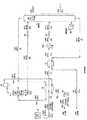
ここで図1を参照する。比較のために、供給流れ中に存在するC2成分及びより重質の炭化水素成分の大部分を含有するNGL生成物を生成するように適合された従来技術のLNG処理プラントの例から説明する。LNGタンク10からの処理されるLNG(流れ41)はポンプ11へ−255°F[−159℃]で入る。ポンプ11は、LNGが熱交換器を通り、そこから分離器15へ流れることができるように十分にLNGの圧力を上げる。ポンプを出る流れ41aは、熱交換器12及び13において、−120°F[−84℃]のガス流れ52及び80°F[27℃]の脱メタン塔底部液体生成物(流れ51)との熱交換により加熱される。For convenience, process parameters are shown in both traditional British units and International Unit Organization (SI) units. The molar flow rates in the table can be interpreted as either pound moles / hour or kg moles / hour. Energy consumption, expressed as horsepower (HP) and / or 1000 British thermal units / hour (MBTU / Hr), corresponds to a stated molar flow rate in pound moles / hour. The energy consumption, expressed as kilowatts (kW), corresponds to a nominal molar flow rate of kg moles / hour.
DESCRIPTION OF THEPRIOR ART Reference is now made to FIG. For comparison, illustrating the example of C2 components and heavier adapted prior art LNG processing plant in to produce NGL product containing most of the hydrocarbon components present in the feed stream . The LNG to be processed (stream 41) from the
加熱された流れ41cは、−163°F[−108℃]及び230psia[1,586kPa(a)]で分離器15に入り、そこで蒸気(流れ46)が残りの液体(流れ47)から分離される。流れ47は、ポンプ28によってより高圧にされ、次に、コントロールバルブ20によって精留塔21の操作圧(およそ430psia[2,965kPa(a)])に膨張され、塔頂部供給流れ(流れ47b)として精留塔へ供給される。
一般に脱メタン塔と呼ばれる精留塔16は、垂直に間隔を置いて配置された複数のトレー、1つ又はそれより多い充填床、又はトレーと充填物との組合せを含む慣用的な蒸留塔である。トレー及び/又は充填物は、塔を下方に流れる液体と上方に上昇する蒸気との間の必要な接触を提供する。また、精留塔は、塔を下方に流れる液体の一部を加熱及び蒸発させて、塔を上昇するストリッピング蒸気をもたらす、1つ又はそれより多いリボイラー(例えば、リボイラー25)を含む。これらの蒸気により、メタンが液体からストリップされ、その結果、底部液体生成物(流れ51)はメタンを実質的に含まず、LNG供給流れに含有されるC2成分及び重質炭化水素の大部分を含む。(塔リボイラーで必要とされる温度レベルのため、リボイラーへの入熱の提供には、この実施例で用いられる加熱媒体のような高いレベルのユーティリティ熱源が一般に必要である。)体積基準でメタン留分0.005という底部生成物における一般的な規格に基づいて、液体生成物流れ51は塔の底を80°F[27℃]で出る。液体生成物(流れ51a)は、前述のように熱交換器13において43°F[6℃]に冷却された後、貯蔵又は更なる処理へ流れる。A rectification column 16, commonly referred to as a demethanizer, is a conventional distillation column that includes a plurality of vertically spaced trays, one or more packed beds, or a combination of trays and packing. is there. The tray and / or packing provides the necessary contact between the liquid flowing down the column and the vapor rising upward. The rectification tower also includes one or more reboilers (eg, reboiler 25) that heat and evaporate a portion of the liquid flowing down the tower, resulting in stripping vapor that rises up the tower. These vapors cause methane to be stripped from the liquid so that the bottom liquid product (stream 51) is substantially free of methane and the majority of the C2 components and heavy hydrocarbons contained in the LNG feed stream. including. (Because of the temperature levels required by the tower reboiler, providing heat input to the reboiler generally requires a high level of utility heat source, such as the heating medium used in this example.) Methane on a volume basis Based on the general specification for a bottom product of 0.005 fraction,
分離器15からの蒸気流れ46は、圧縮機27(外部電源によって動く)に入り、より高圧に圧縮される。得られる流れ46aは、脱メタン塔21を−130°F[−90℃]で通り過ぎる脱メタン塔オーバーヘッド蒸気、流れ48と組合わせられ、−120°F[−84℃]のメタンに富む残留ガス(流れ52)を生成し、これはその後、前述のように熱交換器12において−143°F[−97℃]に冷却されて流れが完全に凝縮される。次に、ポンプ32により、その後の蒸発及び/又は輸送のために、凝縮液体(流れ52a)が1365psia[9,411kPa(a)](流れ52b)にポンプ加圧される。 Vapor
図1に示す方法の流れの流速とエネルギー消費の概要を次表に示す: The following table summarizes the flow velocity and energy consumption for the method shown in FIG.

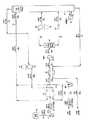
図2は、図1で用いた従来技術のプロセスよりも低いユーティリティ消費で幾分高い回収レベルを達成することができる米国特許出願公開番号US2003/0158458 A1による別の従来技術のプロセスを示す。図2のプロセスは、供給流れ中に存在するC2成分及び重質炭化水素成分の大部分を含有するNGL生成物を生成するのに適合させたものであり、図1について既に説明したのと同じLNG組成及び条件を適用している。FIG. 2 shows another prior art process according to US Patent Application Publication No. US2003 / 0158458 A1, which can achieve a somewhat higher recovery level with lower utility consumption than the prior art process used in FIG. The process of FIG. 2 is adapted to produce an NGL product containing the majority of the C2 and heavy hydrocarbon components present in the feed stream, as previously described for FIG. The same LNG composition and conditions are applied.
図2のプロセスのシミュレーションでは、LNGタンク10からの処理すべきLNG(流れ41)はポンプ11へ−255°F[−159℃]で入る。ポンプ11はLNGの圧力を充分に高め、その結果LNGは熱交換器を通って精留塔21へ流れることができる。ポンプを出る流れ41aは、−130°F[−90℃]の塔オーバーヘッド蒸気流れ48、−122°F[−86℃]の圧縮された蒸気流れ52a、及び85°F[29℃]の脱メタン塔底部液体生成物(流れ51)との熱交換により熱交換器12及び13において加熱される。次いで、部分的に加熱された流れ41cは、熱交換器14において低レベルユーティリティ熱を用いて−120°F[−84℃]に更に加熱される(流れ41d)。(高レベルユーティリティ熱は、通常、低レベルユーティリティ熱より費用がかかるので、この例で用いられる海水のような低レベル熱の使用を最大にし、高レベル熱の使用を最小にすると、通常は低い操作コストが達成される。)流れ41eは、コントロールバルブ20によって精留塔21の操作圧(およそ450psia[3,103kPa(a)])に膨張された後、塔中央の供給位置へ約−123°F[−86℃]で流れる。 In the simulation of the process of FIG. 2, the LNG (stream 41) to be processed from the
塔21中の脱メタン塔は、間隔を置いて垂直に配置された多数のトレー、1つ又はそれより多い充填床、あるいはトレーと充填物とのいくつかの組み合わせを含む慣用的な蒸留塔である。天然ガス処理プラントにおいて多くの場合そうであるように、精留塔は2つの区分からなりうる。上段の吸収(精留)区分21aは、上昇する蒸気と下方に流れる冷たい液体との間の必要な接触を提供するトレー及び/又は充填物を含む、エタン及びより重質な成分を凝縮し吸収する;下段のストリッピング(脱メタン)区分21bは、下方に流れる液体と上昇する蒸気との間の必要な接触を提供するトレー及び/又は充填物を含む。また、脱メタン区分は、塔を流れ落ちる液体の一部を加熱及び蒸発させて塔の上方に流れるストリッピング蒸気を提供する1つ又はそれより多いリボイラー(例えばリボイラー25)を含む。これらの蒸気により、メタンが液体からストリップされ、その結果、底部液体生成物(流れ51)はメタンを実質的に含まず、LNG供給流れに含まれるC2成分及び重質炭化水素のうち大部分を含む。The demethanizer tower in
オーバーヘッド流れ48は精留塔の上段の区分を−130°F[−90℃]で通り抜け、熱交換器12へ流れ、そこで、前述のように冷たいLNG(流れ41a)との熱交換によって−135°F[−93℃]に冷却され、部分的に凝縮される。部分的に凝縮された流れ48aは、還流分離器26に入り、そこで凝縮液(流れ53)が非凝縮蒸気(流れ52)から分離される。還流分離器26からの液体流れ53は、還流ポンプ28によって脱メタン塔21の操作圧よりわずかに高い圧力に加圧され、次いで流れ53bは、冷たい塔頂部供給流れ(還流)として脱メタン塔21へコントロールバルブ30によって供給される。この冷たい液体還流は、脱メタン塔21の上段の吸収(精留)区分21aを上昇する蒸気からC2成分及び重質炭化水素成分を吸収及び凝縮する。
底部生成物において体積基準で0.005のメタン留分に基づいて、液体生成物流れ51は、精留塔21の底を85°F[29℃]で出る。これまでに説明したように熱交換器13において0°F[−18℃]に冷却された後、液体生成物(流れ51a)は貯蔵又は更なる処理へ流れる。還流分離器26を通り抜けるメタンに富む残留ガス(流れ52)は、圧縮機27(外部電源によって動く)によって493psia[3,400kPa(a)](流れ52a)に圧縮され、それによって流れは、前述のように熱交換器12において−136°F[−93℃]に冷却させるときに、完全に凝縮させることができる。次に、ポンプ32により、その後の蒸発及び/又は輸送のために、凝縮液体(流れ52b)を1365psia[9,411kPa(a)](流れ52c)にポンプ加圧する。 Based on a methane fraction of 0.005 by volume in the bottom product, the
図2に示す方法の流れの流量とエネルギー消費の概要は次表に示す: An overview of the flow rate and energy consumption of the method shown in Figure 2 is given in the following table:
図2の従来技術のプロセスについての上記表IIに示した回収レベルを図1の従来法についての表Iの回収レベルと比較すると、図2のプロセスは本質的に同じエタン回収率とわずかに高いプロパン及びブタン+回収率を達成できることを示している。表IIのユーティリティ消費を表Iのユーティリティ消費と比較すると、図2のプロセスは図1のプロセスよりも必要とする電力及び高レベルユーティリティ熱は少ない。図2のプロセスにおいて、脱メタン塔21について還流流れを用いて、塔におけるエタン及びより重質の成分をより効率的に回収することにより、電力の低減が達成される。これはつまり、図1のプロセスよりも高い塔供給温度を可能とし、塔供給流れを加熱する熱交換器14において低レベルユーティリティ熱を用いることにより、脱メタン塔21(高レベルユーティリティ熱を用いる)でのリボイラー加熱需要が低減される。(図1のプロセスは底部生成物流れ51aを−43°F[6℃]に冷却するのに対し、図2のプロセスでは0°F[−18℃]が望ましいことに注目されたい。)図1のプロセスの場合、流れ51aをより低い温度に冷却しようとする試みは、リボイラー25の高レベルユーティリティ熱需要を減じるが、同じ回収効率を維持するつもりならば分離器15の操作圧は低くしなければならないので、分離器15に入る流れ41cについて得られるより高い温度により、蒸気圧縮機27の電力使用量を不釣合いに増加させる。)
発明の説明
実施例1
図3は本発明によるプロセスの流れ図を示す。図3に示すプロセスで検討されるLNG組成及び条件は図1及び2と同じである。したがって、図3のプロセスを図1及び図2のプロセスと比較して、本発明の利点を説明することができる。Comparing the recovery levels shown in Table II above for the prior art process of FIG. 2 with the recovery levels of Table I for the prior art process of FIG. 1, the process of FIG. 2 is essentially slightly higher with the same ethane recovery rate. It shows that propane and butane + recovery can be achieved. Comparing the utility consumption of Table II with the utility consumption of Table I, the process of FIG. 2 requires less power and high level utility heat than the process of FIG. In the process of FIG. 2, power reduction is achieved by using reflux flow for the
Description of the invention
Example 1
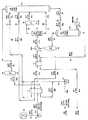
FIG. 3 shows a process flow diagram according to the present invention. The LNG composition and conditions studied in the process shown in FIG. 3 are the same as those in FIGS. Therefore, the process of FIG. 3 can be compared with the process of FIGS. 1 and 2 to illustrate the advantages of the present invention.
図3のプロセスのシミュレーションでは、LNGタンク10からの処理すべきLNG(流れ41)はポンプ11へ−255°F[−159℃]で入る。ポンプ11は、熱交換器を通って分離器15へ流れることができるように十分にLNGの圧力を高める。ポンプを出る流れ41aは2つの部分、流れ42及び43に分離される。第1の部分である流れ42は、バルブ17によって精留塔21の操作圧(約450psia[3,103kPa(a)])に膨張され、上段の塔中央供給位置で塔へ供給される。第2の部分である流れ43は、その全て又は一部が蒸発されるように、分離器15に入る前に加熱される。図3に示す実施例では、流れ43は、−112°F[−80℃]の圧縮されたオーバーヘッド蒸気流れ48a、−129°F[−90℃]の還流流れ53及び85°F[29℃]の塔からの液体生成物(流れ51)を冷却することによって、熱交換器12及び13において−106°F[−77℃]にまず加熱される。部分的に加熱された流れ43bは、次に、低レベルのユーティリティ熱を用いて熱交換器14において更に加熱される(流れ43c)。いずれの場合においても、交換器12、13及び14は、多数の個々の熱交換器、又は単一のマルチパス熱交換器、又はそれらの組み合わせのいずれかに相当する。(表示された加熱役務に1つより多い熱交換器を使用するかどうかの決定は、これらに限定されないが、流入LNG流量、熱交換器のサイズ、流れの温度等を含む多くの因子に依存する。)
加熱された流れ43cは分離器15に−62°F[−52℃]及び625psia[4,309kPa(a)]で入り、そこで、蒸気(流れ46)は残留液体(流れ47)から分離される。分離器15からの蒸気(流れ46)はワークエクスパンジョンマシーン18に入り、そこで、機械的エネルギーがこの高圧供給流れの部分から抽出される。マシーン18は蒸気を実質的に等エントロピー的に塔操作圧に膨張させ、ワークエクスパンジョンは膨張した流れ46aを約−85°F[−65℃]の温度に冷却する。一般に商業的に入手しうるエキスパンダーは、理想的等エントロピー膨張で理論的に利用可能な80〜88%程度の仕事を取り戻すことが可能である。回収された仕事は、例えば、塔オーバーヘッド蒸気(流れ48)の再圧縮に用いることができる遠心圧縮機(例えば部品19)を動かすのにしばしば用いられる。膨張され部分的に凝縮された流れ46aは、その後、供給流れとして精留塔21へ塔中央供給位置で供給される。分離器液体(流れ47)は膨張バルブ20によって精留塔21の操作圧に膨張され、流れ47aが約−77°F[−61℃]に冷却された後、精留塔21へ下段の塔中央供給位置で供給される。In the simulation of the process of FIG. 3, the LNG (stream 41) to be processed from the
精留塔21中の脱メタン塔は、間隔を置いて垂直に配置された多数のトレー、1つ又はそれより多い充填床、あるいはトレーと充填物とのいくつかの組み合わせを含む慣用的な蒸留塔である。図2に示す精留塔と同様に、図3の精留塔は2つの区分からなりうる。上段の吸収(精留)区分は、上昇する蒸気と下方に流れる冷たい液体との間の必要な接触を提供してエタン及びより重質な成分を凝縮及び吸収するトレー及び/又は充填物を含む;下段のストリッピング(脱メタン)区分は、下方に流れる液体と上昇する蒸気との間の必要な接触を提供するトレー及び/又は充填物を含む。脱メタン区分はまた、塔を下方に流れる液体部分を加熱及び蒸発させて塔の上方に流れるストリッピング蒸気を提供する1つ又はそれより多いリボイラー(例えばリボイラー25)を含む。底部生成物の体積基準で0.005のメタン留分に基づいて、液体生成物流れ51は塔の底を85°F[29℃]で出る。前述のように熱交換器13中において0°F[−18℃]に冷却された後、液体生成物(流れ51a)は貯蔵又は更なる処理へ流れる。 The demethanizer column in the
オーバーヘッド蒸気流れ48は、精留塔21の上段区分から−134°F[−92℃]で取り出され、エクスパンジョンマシーン18によって動く圧縮機19へ流れ、そこで、550psia[3,789kPa(a)]に圧縮される(流れ48a)。この圧力で、流れは前述のように熱交換器12中で−129°F[−90℃]に冷却されるにつれて、全て凝縮される。次に、凝縮された液体(流れ48b)は2つの部分、流れ52及び53に分けられる。第1の部分(流れ52)はメタンに富む希薄LNG流れであり、これは次に、その後の蒸発及び/又は輸送のためにポンプ32によって1365psia[9,411kPa(a)]にポンプ加圧される(流れ52a)。
残りの部分は還流流れ53であり、これは熱交換器12へ流れ、そこで、前述のように冷たいLNG(流れ43)の一部との熱交換によって−166°F[−110℃]に二次冷却される。二次冷却された還流流れ53aは、膨張バルブ30によって脱メタン塔21の操作圧に膨張され、次に、膨張された流れ53bは冷たい塔頂部供給流れ(還流)として脱メタン塔21へ供給される。この冷たい液体還流は、脱メタン塔21の上段の精留区分の上昇蒸気からのC2成分及びより重質の炭化水素成分を吸収及び凝縮する。The remaining portion is the
図3に示すプロセスの流れの流量とエネルギー消費の概要は次表に示す: A summary of the flow and energy consumption of the process flow shown in Figure 3 is shown in the following table:
図3のプロセスについての上記表IIIに示した回収レベルを図1の従来技術のプロセスについての表Iの回収レベルと比較すると、本発明はエタン回収率が同等であり、プロパン回収率(99.89%対98.33%)及びブタン+回収率(100%対99.62%)は図1のプロセスよりわずかに高いことを示している。しかしながら、表IIIのユーティリティ消費を表Iのユーティリティ消費と比較すると、本発明に必要とされる電力及び高レベルユーティリティ熱はいずれも図1のプロセスの場合よりもはるかに低いことを示している(それぞれ、26%及び64%低い)。 Comparing the recovery levels shown in Table III above for the process of FIG. 3 with the recovery levels of Table I for the prior art process of FIG. 1, the present invention has comparable ethane recovery rates and propane recovery rates (99. 89% vs. 98.33%) and butane + recovery (100% vs. 99.62%) are shown to be slightly higher than the process of FIG. However, comparing the utility consumption of Table III with the utility consumption of Table I shows that both the power and high level utility heat required for the present invention are much lower than for the process of FIG. 1 ( 26% and 64% lower respectively).
表IIIに示した回収レベルを図2の従来技術のプロセスについての表IIの回収レベルと比較すると、本発明は図2のプロセスの液体回収率に本質的に匹敵することを示している。(プロパン回収率のみがわずかに低い、99.89%対100%)。しかしながら、表IIIのユーティリティ消費を表IIのユーティリティ消費と比較すると、本発明に必要とされる電力及び高レベルユーティリティ熱はいずれも図2のプロセスの場合よりも著しく低い(それぞれ、11%及び53%低い)ことを示している。 Comparing the recovery levels shown in Table III with the recovery levels in Table II for the prior art process of FIG. 2, it is shown that the present invention is essentially comparable to the liquid recovery of the process of FIG. (Only propane recovery is slightly lower, 99.89% vs. 100%). However, comparing the utility consumption in Table III with the utility consumption in Table II, both the power and high level utility heat required for the present invention are significantly lower than in the process of FIG. 2 (11% and 53%, respectively). % Lower).
本発明の改良された効率の理由を説明する要素は主に3つある。第1に、図1の従来技術のプロセスと比較して、本発明は、精留塔21への還流として直接働くために、LNG供給流れ自体に依存しない。それどころか、冷たいLNGに本来備わっている冷却作用を熱交換器12において用いて、回収すべき非常にわずかなC2成分及びより重質の炭化水素成分を含有する液体還流流れ(流れ53)を生じさせることにより、精留塔21の上段の吸収区分において効率的な精留が行なわれ、図1の従来技術のプロセスの平衡制限が回避される。第2に、図1及び図2の従来技術のプロセスと比較して、精留塔21への供給前にLNG供給流れが2つの部分に分かれることで、低レベルユーティリティ熱のより効果的な利用が可能となり、それによって、リボイラー25によって消費される高レベルユーティリティ熱の量が低減される。LNG供給流れの相対的に冷たい部分(図3の流れ42a)は、精留塔21への補助的な還流流れとして働いて、膨張された蒸気及び液体流れ(図3の流れ46a及び47a)の蒸気を部分的に精留して、このLNG供給流れの部分(流れ43)の加熱及び部分的蒸発により熱交換器12の負荷が過度に高められないようにする。第3に、図2の従来技術のプロセスと比較して、表IIIの流れ53を表IIの流れ53と比較することによって分かるように、LNG供給流れの一部(図3の流れ42a)を補助的な還流流れとして用いることによって、精留塔21への頂部還流流れをより少なくすることが可能となる。頂部還流の低減と、それに加えて熱交換器14において低レベルユーティリティ熱を用いる高度の加熱(表IIIと表IIを比較することによって分かるように)の結果として、精留塔21へ供給する全液体はより少なくなり、リボイラー25で求められる働きが低減され、脱メタン塔からの底部液体生成物に対する規格を満たすのに必要な高レベルユーティリティ熱の量をできるだけ少なくする。There are three main factors that explain the reasons for the improved efficiency of the present invention. First, compared to the prior art process of FIG. 1, the present invention does not rely on the LNG feed stream itself to act directly as reflux to the
実施例2
本発明の別の態様は図4に示す。図4に示すプロセスで検討されるLNG組成及び条件は、図3、並びに図1及び図2で記載したものと同じである。したがって、本発明の図4のプロセスは図3に示す態様及び図1及び2に示す従来技術のプロセスと比較することができる。Example 2
Another embodiment of the present invention is shown in FIG. The LNG composition and conditions studied in the process shown in FIG. 4 are the same as those described in FIG. 3 and FIGS. Therefore, the process of FIG. 4 of the present invention can be compared to the embodiment shown in FIG. 3 and the prior art process shown in FIGS.
図4のプロセスのシミュレーションでは、LNGタンク10からの処理すべきLNG(流れ41)は、ポンプ11へ−255°F[−159℃]で入る。ポンプ11は、熱交換器を通って分離器15へ流れることができるように十分にLNGの圧力を高める。ポンプを出る流れ41aは、その全て又は一部が蒸発されるように、分離器15に入る前に加熱される。図4に示す実施例では、流れ41aは、−63°F[−53℃]の圧縮されたオーバーヘッド蒸気流れ48b、−135°F[−93℃]の還流流れ53及び85°F[29℃]の塔からの液体生成物(流れ51)を冷却することによって、熱交換器12及び13において−99°F[−73℃]にまず加熱される。部分的に加熱された流れ41cは、次に、低レベルのユーティリティ熱を用いて熱交換器14において更に加熱される(流れ41d)。 In the simulation of the process of FIG. 4, the LNG (stream 41) to be processed from the
加熱された流れ41dは分離器15に−63°F[−53℃]及び658psia[4,537kPa(a)]で入り、そこで、蒸気(流れ44)は残留液体(流れ47)から分離される。分離器の液体(流れ47)は膨張バルブ20によって精留塔21の操作圧450psia[3,103kPa(a)]に膨張され、流れ47aが約−82°F[−63℃]に冷却された後、精留塔21へ下段の塔中央供給位置で供給される。
分離器15からの蒸気(流れ44)は2つの流れ45及び46に分けられる。全体蒸気の約30%を含む流れ45は、−134°F[−92℃]の冷たい脱メタン塔オーバーヘッド蒸気との熱交換関係にある熱交換器16を通過し、そこで、冷却されて十分に凝縮する。次に、結果として得られる実質的に凝縮された−129°F[−89℃]の流れ45aは、膨張バルブ17により精留塔21の操作圧にフラッフュ膨張される。膨張の間、流れの一部は蒸発され、流れ全体が冷却される。図4に示すプロセスでは、膨張バルブ17を出る膨張された流れ45bは、−133°F[−92℃]の温度に達し、精留塔21へ上段の塔中央供給位置で供給される。 The vapor from the separator 15 (stream 44) is split into two
分離器15からの蒸気の残りの70%(流れ46)は、ワークエクスパンジョンマシーン18に入り、そこで、機械的エネルギーがこの高圧供給流れの部分から抽出される。マシーン18は蒸気を実質的に等エントロピー的に塔操作圧に膨張させ、ワークエクスパンジョンは、膨張した流れ46aを約−90°F[−68℃]の温度に冷却する。膨張され部分的に凝縮された流れ46aは、その後、供給流れとして精留塔21へ塔中央供給位置で供給される。 The remaining 70% of steam from the separator 15 (stream 46) enters the
底部生成物の体積基準で0.005のメタン留分に基づいて、液体生成物流れ51は塔の底を85°F[29℃]で出る。前述のように熱交換器13において0°F[−18℃]に冷却された後、液体生成物(流れ51a)は貯蔵又は更なる処理へ流れる。 Based on a methane fraction of 0.005 on a bottom product volume basis, the
オーバーヘッド蒸留流れ48は精留塔21の上部区分から−134°F[−92℃]で取り出され、熱交換器16中を入ってくる供給ガスに対して向流的に通過し、そこで、−78°F[−61℃]に加熱される。加熱された流れ48aはエクスパンジョンマシーン18によって動く圧縮機19へ流れ、そこで、498psia[3,430kPa(a)]に圧縮される(流れ48b)。この圧力で、流れは前述のように熱交換器12中で−135°F[−93℃]に冷却されるにつれて全て凝縮される。次に、凝縮された液体(流れ48c)は2つの部分、流れ52及び53に分けられる。第1の部分(流れ52)はメタンに富む希薄LNG流れであり、これは次に、その後の蒸発及び/又は輸送のためにポンプ32によって1365psia[9,411kPa(a)]にポンプ加圧される(流れ52a)。
残りの部分は還流流れ53であり、これは熱交換器12へ流れ、そこで、前述のように冷たいLNG(流れ41a)との熱交換によって−166°F[−110℃]に二次冷却される。二次冷却された還流流れ53aは、膨張バルブ30によって脱メタン塔21の操作圧に膨張され、次に、膨張された流れ53bは冷たい塔頂部供給流れ(還流)として脱メタン塔21へ供給される。この冷たい液体還流は、脱メタン塔21の上段の精留区分の上昇蒸気からのC2成分及びより重質の炭化水素成分を吸収及び凝縮する。The remaining portion is the
図4に示すプロセスの流れの流量とエネルギー消費の概要は次表に示す: A summary of the flow and energy consumption of the process flow shown in Figure 4 is shown in the following table:
本発明の図4の態様についての上記表IVを本発明の図3の態様についての表IIIと比較すると、液体回収率は図4の態様の場合、本質的に同じであることを示している。図4の態様は塔オーバーヘッド(流れ48)を用いて、熱交換器16中で分離器15の蒸気(流れ45)の一部を凝縮及び二次冷却することにより、精留塔21への補充的な還流(流れ45b)を生じ、圧縮機19に入るガス(流れ48a)は図3の態様における相当する流れ(流れ48)よりもかなり温かい。この役務に使用される圧縮装置の種類に依存して、温かい温度により、冶金学的見地等から利点が提供され得る。しかしながら、精留塔21へ供給される補充的な還流流れ45bは、図3の態様における流れ42aほど冷たくなく、頂部還流(流れ53b)はより多く必要とされ、熱交換器14で用いられる低レベルユーティリティ熱はより少ない。これは、図3の態様と比較して、本発明の図4の態様によって必要とされるリボイラー25の負荷を高めかつ高レベルユーティリティ熱の量を高める。高い頂部還流流量もまた、図3の態様と比較して図4の態様に必要な電力をわずかに(約2%の差で)増加させる。個々の用途にどの態様を用いるかの選択は、電力及び高レベルユーティリティ熱の相対的なコスト、並びにポンプ、熱交換器及び圧縮機の相対的な資本コストによって一般に決定される。 Comparison of Table IV above for the embodiment of FIG. 4 of the present invention with Table III for the embodiment of FIG. 3 of the present invention shows that the liquid recovery is essentially the same for the embodiment of FIG. . The embodiment of FIG. 4 uses column overhead (stream 48) to replenish the
実施例3
本発明のより簡単な別の態様は図5に示す。図5に示すプロセスで検討されるLNG組成及び条件は、図3及び図4、並びに図1及び2に記載したものと同じである。したがって、本発明の図5のプロセスは、図3及び4に示す態様及び図1及び2に示す従来技術のプロセスと比較することができる。Example 3
Another simpler embodiment of the present invention is shown in FIG. The LNG composition and conditions studied in the process shown in FIG. 5 are the same as those described in FIGS. 3 and 4 and FIGS. Thus, the process of FIG. 5 of the present invention can be compared to the embodiment shown in FIGS. 3 and 4 and the prior art process shown in FIGS.
図5のプロセスのシミュレーションでは、LNGタンク10からの処理すべきLNG(流れ41)は、ポンプ11へ−255°F[−159℃]で入る。ポンプ11は、熱交換器を通って分離器15へ流れることができるように十分にLNGの圧力を高める。ポンプを出る流れ41aは、その全て又は一部が蒸発されるように、分離器15に入る前に加熱される。図5に示す実施例では、流れ41aは、−110°F[−79℃]の圧縮されたオーバーヘッド蒸気流れ48a、−128°F[−89℃]の還流流れ53及び85°F[29℃]の塔からの液体生成物(流れ51)を冷却することによって、熱交換器12及び13において−102°F[−75℃]にまず加熱される。部分的に加熱された流れ41cは、次に、低レベルのユーティリティ熱を用いて熱交換器14において更に加熱される(流れ41d)。 In the simulation of the process of FIG. 5, the LNG (stream 41) to be processed from the
加熱された流れ41dは、分離器15に−74°F[−59℃]及び715psia[4,930kPa(a)]で入り、そこで、蒸気(流れ46)は残留液体(流れ47)から分離される。分離器の蒸気(流れ46)はワークエクスパンジョンマシーン18に入り、そこで、機械的エネルギーがこの高圧供給流れの部分から抽出される。マシーン18は蒸気を実質的に等エントロピー的に塔操作圧(約450psia[3,103kPa(a)])に膨張させ、ワークエクスパンジョンは膨張した流れ46aを約−106°F[−77℃]の温度に冷却する。膨張され部分的に凝縮された流れ46aは、その後、供給流れとして精留塔21へ塔中央供給位置で供給される。分離器液体(流れ47)は膨張バルブ20によって精留塔21の操作圧に膨張され、流れ47aが約−99°F[−73℃]に冷却された後、精留塔21へ下段の塔中央供給位置で供給される。
底部生成物の体積基準で0.005のメタン留分に基づいて、液体生成物流れ51は精留塔21の底を85°F[29℃]で出る。前述のように熱交換器13中で0°F[−18℃]に冷却された後、液体生成物(流れ51a)は貯蔵又は更なる処理へ流れる。 Based on a methane fraction of 0.005 on a bottom product volume basis, the
オーバーヘッド蒸気流れ48は、精留塔21の上段の区分から−134°F[−92℃]で取り出され、エクスパンジョンマシーン18によって動く圧縮機19へ流れ、そこで、563psia[3,882kPa(a)]に圧縮される(流れ48a)。この圧力で、流れは前述のように熱交換器12において−128°F[−89℃]に冷却されるにつれて、全て凝縮される。次に、凝縮された液体(流れ48b)は2つの部分、流れ52及び53に分けられる。第1の部分(流れ52)はメタンに富む希薄LNG流れであり、これは次に、その後の蒸発及び/又は輸送のためにポンプ32によって1365psia[9,411kPa(a)]にポンプ加圧される(流れ52a)。
残りの部分は還流流れ53であり、これは熱交換器12へ流れ、そこで、前述のように冷たいLNG(流れ41a)との熱交換によって−184°F[−120℃]に二次冷却される。二次冷却された還流流れ53aは、膨張バルブ30によって脱メタン塔21の操作圧に膨張され、次に、膨張された流れ53bは冷たい塔頂部供給流れ(還流)として脱メタン塔21へ供給される。この冷たい液体還流は、脱メタン塔21の上段の精留区分の上昇蒸気からのC2成分及びより重質の炭化水素成分を吸収及び凝縮する。The remaining part is the
図5に示すプロセスの流れの流量とエネルギー消費の概要は次表に示す: An overview of the flow and energy consumption of the process flow shown in Figure 5 is shown in the following table:
本発明の図5の態様についての上記表Vを本発明の図3の態様についての表III及び図4の態様についての表IVと比較すると、液体回収率は図5の態様の場合、本質的に同じであることを示している。図5の態様は図3及び図4のような精留塔21への補充的な還流(それぞれ、流れ42a及び45b)を用いないので、より多くの頂部還流(流れ53b)が必要とされ、熱交換器14で用いられる低レベルユーティリティ熱はより少ない。これは、図3及び図4の態様と比較して、本発明の図5の態様によって必要とされるリボイラー25の負荷を高めかつ高レベルユーティリティ熱の量を高める。より高い頂部還流流量もまた、図3及び図4の態様と比較して図5の態様の電力需要をわずかに(それぞれ、約5%及び3%の差で)増加させる。個々の用途にどの態様を用いるかの選択は、電力及び高レベルユーティリティ熱の相対的なコスト、並びに塔、ポンプ、熱交換器及び圧縮機の相対的な資本コストによって一般に決定される。 Comparing Table V above for the embodiment of FIG. 5 of the present invention with Table III for the embodiment of FIG. 3 of the present invention and Table IV for the embodiment of FIG. 4, the liquid recovery is essentially the case for the embodiment of FIG. Is the same. Since the embodiment of FIG. 5 does not use supplemental reflux (streams 42a and 45b, respectively) to the
実施例4
より少ない電力消費で同じC2成分回収率を維持するわずかに複雑な設計は、図6のプロセスで説明する本発明の別の態様を用いて達成することができる。図6に示すプロセスで検討されるLNG組成及び条件は、図3〜図5、並びに図1及び図2に記載したものと同じである。したがって、本発明の図6のプロセスは図3〜図5に示す態様及び図1及び図2に示す従来技術のプロセスと比較することができる。Example 4
A slightly more complex design that maintains the same C2 component recovery with less power consumption can be achieved using another aspect of the invention described in the process of FIG. The LNG composition and conditions studied in the process shown in FIG. 6 are the same as those described in FIGS. 3 to 5 and FIGS. 1 and 2. Therefore, the process of FIG. 6 of the present invention can be compared with the embodiment shown in FIGS. 3-5 and the prior art process shown in FIGS.
図6のプロセスのシミュレーションでは、LNGタンク10からの処理すべきLNG(流れ41)は、ポンプ11へ−255°F[−159℃]で入る。ポンプ11は、熱交換器を通って吸収塔21へ流れることができるように十分にLNGの圧力を高める。図6に示す実施例では、ポンプを出る流れ41aはまず、−129°F[−90℃]の接触及び分離装置吸収塔21から取り出されたオーバーヘッド蒸気(蒸留流48)及び83°F[−63℃]の精留ストリッパー塔24から取り出されたオーバーヘッド蒸気(蒸留流50)を冷却することによって、熱交換器12において−120°F[−84℃]に加熱される。次に、部分的に加熱された液体流れ41bは2つの部分、流れ42及び43に分けられる。第1の部分である流れ42は、バルブ17によって精留塔21の操作圧(約495psia[3,413kPa(a)])に膨張され、下段の塔中央供給位置で塔へ供給される。 In the process simulation of FIG. 6, the LNG (stream 41) to be processed from the
第2の部分である流れ43は、その全て又は一部が蒸発されるように、吸収塔21へ入る前に加熱される。図6に示す実施例では、流れ43は、88°F[31℃]の精留ストリッパー塔24からの液体生成物(流れ51)を冷却することによって、−112°F[−80℃]にまず加熱される。部分的に加熱された流れ43aは、次に、低レベルのユーティリティ熱を用いて熱交換器14中で更に加熱される(流れ43b)。部分的に蒸発させられた流れ43bは膨張バルブ20によって吸収塔21の操作圧に膨張され、−67°F[−55℃]に冷却された後、吸収塔21へ下段の塔供給位置で供給される。膨張された流れ43cの液体部分(もしあれば)は、吸収塔21の上段区分から下方に流れる液体と混ざり、一緒になった液体流れ49は吸収塔21の底を−79°F[−62℃]で出る。膨張された流れ43cの蒸気部分は、吸収塔21を上昇し、C2成分及びより重質の炭化水素成分を凝縮及び吸収する下方に流れる冷たい液体と接触する。The second part,
接触装置吸収塔21の底からの一緒になった液体流れ49は膨張バルブ22によってストリッパー塔24の操作圧(465psia[3,206kPa(a)])よりわずかに高い圧力にフラッシュ膨張され、流れ49が−83°F[−64℃]に冷却された後、塔頂部供給位置にて精留ストリッパー塔24へ入る。ストリッパー塔24において、流れ49aは、体積基準で0.005のメタン留分の一般的な規格を満たすようにリボイラー25で生じた蒸気によってメタンがストリップされる。生じた液体生成物51は、ストリッパー塔24の底を88°F[31℃]で出て、前述のように熱交換器13において0°F[−18℃]に冷却され(流れ51a)、次いで、貯蔵又は更なる処理へ流れる。 The combined
ストリッパー塔24からのオーバーヘッド蒸気(流れ50)は、塔を−83°F[−64℃]出て、熱交換器12へ流れ、そこで、前述のように−132°F[−91℃]に冷却されて、流れ全てが凝縮される。次に、凝縮された液体流れ50aはオーバーヘッドポンプ33へ入り、そこで、流れ50bの圧力は吸収塔21の操作圧よりわずかに高い圧力に上げられる。コントロールバルブ35によって吸収塔21の操作圧に膨張させた後、−130°F[−90℃]の流れ50cは、次に吸収塔21へ上段の塔中央供給位置で供給され、そこで、吸収塔21の上段区分から下方に流れる液体と混ざり、吸収塔21の下段区分からの上昇蒸気中のC2成分及びより重質の炭化水素成分を捕らえるのに用いられる液体の一部となる。Overhead steam (stream 50) from
吸収塔21の上段区分から−129°F[−90℃]で取り出されたオーバーヘッド蒸気流れ48は、熱交換器12へ流れ、前述のように−135°F[−93℃]に冷却されて、流れ全てが凝縮される。凝縮された液体(流れ48a)は、ポンプ31によって吸収塔21の操作圧よりわずかに高い圧力へポンプ加圧され(流れ48b)、次に、2つの部分、流れ52及び53に分けられる。第1の部分(流れ52)はメタンに富む希薄LNG流れであり、これは次に、その後の蒸発及び/又は輸送のためにポンプ32によって1365psia[9,411kPa(a)]にポンプ加圧される(流れ52a)。 The
残りの部分は還流流れ53であり、これは膨張バルブ30によって吸収塔21の操作圧に膨張される。次に、膨張された流れ53aは冷たい塔頂部供給流れ(還流)として吸収塔21へ−135°F[−93℃]で供給される。この冷たい液体還流は、吸収塔21の上段区分の上昇蒸気からのC2成分及びより重質の炭化水素成分を吸収及び凝縮する。The remaining part is the
図6に示すプロセスの流れの流量とエネルギー消費の概要は次表に示す: An overview of the flow and energy consumption of the process flow shown in FIG. 6 is shown in the following table:
本発明の図6の態様についての上記表VIを本発明の図3〜図5の態様についての表III〜表Vと比較すると、液体回収率は図6の態様の場合、本質的に同じであることを示している。しかしながら、表VIのユーティリティ消費を表III〜表Vのユーティリティ消費と比較すると、本発明の図6で必要とされる電力及び高レベルユーティリティ熱はいずれも図3〜図5の方法の場合よりも低い。図6の態様の電力需要はそれぞれ、1%、4%及び6%低く、高レベルユーティリティ熱需要はそれぞれ、1%、4%及び20%低い。 Comparing Table VI above for the embodiment of FIG. 6 of the present invention with Tables III-V for the embodiment of FIGS. 3-5 of the present invention, the liquid recovery is essentially the same for the embodiment of FIG. It shows that there is. However, comparing the utility consumption in Table VI with the utility consumption in Tables III-V, both the power and high-level utility heat required in FIG. 6 of the present invention are greater than in the method of FIGS. Low. The power demand in the embodiment of FIG. 6 is 1%, 4% and 6% lower, respectively, and the high level utility heat demand is 1%, 4% and 20% lower, respectively.
図3〜図5の態様に比べて本発明の図6で必要とされるユーティリティの減少は、主に2つの要素に起因すると考えられる。第1に、図3〜図5の態様における精留塔21を吸収塔21及びストリッパー塔24に分離することによって、2つの塔の操作圧をそれらのそれぞれ働きのために独立して最適化することができる。図3〜図5の態様における精留塔21の操作圧は、より高い操作圧の結果として生じる蒸留性能への悪影響を招くことなく、示された値よりずっと高い値に上げることはできない。この影響は、その蒸気及び液体流れの相挙動による精留塔21における乏しい物質移動によって現れる。重要な問題は、気液分離効率、すなわち、液体表面張力及び2つの相の密度差に影響を及ぼす物理的性質である。精留操作(吸収塔21)及びストリッピング操作(ストリッパー塔24)の操作圧で、それらは図3〜図5の態様におけるようにもはや連結されず、熱交換器12におけるオーバーヘッド流れ(図6の態様における流れ48)の凝縮を容易にするより高い圧力で精留操作を行いながら、ストリッピング操作を妥当な操作圧で行うことができる。 The reduction in utility required in FIG. 6 of the present invention compared to the embodiment of FIGS. 3-5 is believed to be primarily due to two factors. First, by separating the
第2に、図3及び図4の態様で補充的な還流流れとして用いられるLNG供給流れの一部(図3の流れ42a及び図4の流れ45b)に加えて、本発明の図6の態様は吸収塔21へ第2の補充的な還流流れ(流れ50c)を用いて、吸収塔21の下段区分に入る流れ43cの蒸気の精留を助ける。これによって、熱交換器14における低レベルユーティリティ熱のより最適な使用がリボイラー25への負荷を減少させ、高レベルユーティリティ熱需要を減じる。個々の用途にどの態様を用いるかの選択は、電力及び高レベルユーティリティ熱の相対的なコスト、並びに塔、ポンプ、熱交換器及び圧縮機の相対的な資本コストによって一般に決定される。 Second, in addition to a portion of the LNG feed stream (
実施例5
本発明はまた、図7に示すような供給流れに存在するC3成分及びより重質の炭化水素成分の大部分を含有するLPG生成物を生成するのに適合させることができる。図7に示すプロセスで検討されるLNG組成及び条件は、図1〜図6についてこれまでに説明したものと同じである。したがって、本発明の図7の方法は図1及び図2に示す従来技術のプロセス、並びに図3〜図6に示す本発明の他の態様と比較することができる。Example 5
The present invention can also be adapted to produce LPG product containing most of the hydrocarbon components of the C3 components and heavier present in the feed stream as shown in FIG. The LNG composition and conditions studied in the process shown in FIG. 7 are the same as those described so far for FIGS. Accordingly, the method of FIG. 7 of the present invention can be compared to the prior art process illustrated in FIGS. 1 and 2 and the other aspects of the present invention illustrated in FIGS.
図7のプロセスのシミュレーションでは、LNGタンク10からの処理すべきLNG(流れ41)はポンプ11へ−255°F[−159℃]で入る。ポンプ11は、熱交換器を通って吸収塔21へ流れることができるように十分にLNGの圧力を高める。図7に示す実施例では、ポンプを出る流れ41aはまず、−90°F[−68℃]の接触及び分離装置吸収塔21から取り出されたオーバーヘッド蒸気(蒸留流48)、精留ストリッパー塔24から取り出された57°F[14℃]の圧縮されたオーバーヘッド蒸気(流れ50a)、及び190°F[88℃]の精留ストリッパー塔24からの液体生成物を冷却することによって、熱交換器12及び13において−99°F[−73℃]に加熱される。 In the simulation of the process of FIG. 7, the LNG (stream 41) to be processed from the
次に、部分的に加熱された液体流41cは、低レベルユーティリティ熱を用いて熱交換器14において−43°F[−42℃]に更に加熱される(流れ41d)。部分的に蒸発させられた流れ41dは、膨張バルブ20によって吸収塔21の操作圧(約465psia[3,206kPa(a)])に膨張され、流れ41eが−48°F[−44℃]に冷却された後、吸収塔21へ下段の塔供給位置で供給される。膨張された流れ41eの液体部分(もしあれば)は、吸収塔21の上段区分から下方に流れる液体と混ざり、一緒になった液体流れ49は、吸収塔21の底を−50°F[−46℃]で出る。膨張された流れ41eの蒸気部分は、吸収塔21を上昇し、C3成分及びより重質の炭化水素成分を凝縮及び吸収する下方に流れる冷たい液体と接触する。The partially heated
接触装置吸収塔21の底からの一緒になった液体流れ49は、膨張バルブ22によってストリッパー塔24の操作圧(430psia[2,965kPa(a)])よりわずかに高い圧力にフラッシュ膨張され、流れ49が−53°F[−47℃]に冷却された後、塔頂部供給位置にて精留ストリッパー塔24へ入る。ストリッパー塔24において、流れ49aは、モル基準で0.020:1のエタン対プロパンの規格を満たすようにリボイラー25で生じた蒸気によってメタン及びC2成分をストリップされる。生じた液体生成物51は、ストリッパー塔24の底を190°F[88℃]で出て、前述のように熱交換器13において0°F[−18℃]に冷却され(流れ51a)、次いで、貯蔵又は更なる処理へ流れる。The combined
ストリッパー塔24からのオーバーヘッド蒸気(流れ50)は、塔を30°F[−1℃]出て、オーバーヘッド圧縮機34(補充電源によって動く)に流れ、そこで、流れ50aの圧力は吸収塔21の操作圧よりわずかに高い圧力に上げられる。流れ50aは熱交換器12に入り、そこで、前述のように−78°F[−61℃]に冷却され、流れ全てが凝縮される。凝縮された液体流れ50bは、コントロールバルブ35によって吸収塔21の操作圧に膨張され、次に、得られる−84°F[−64℃]の流れ50cは、吸収塔21へ塔中央供給位置で供給され、そこで、吸収塔21の上段区分から下方に流れる液体と混ざり、吸収塔21の下段区分からの上昇蒸気中のC3成分及びより重質の炭化水素成分を捕らえるのに用いられる液体の一部となる。Overhead steam (stream 50) from
吸収塔21の上段区分から−90°F[−68℃]で取り出されたオーバーヘッド蒸気流れ48は、熱交換器12へ流れ、前述のように−132°F[−91℃]に冷却されて、流れ全てが凝縮される。凝縮された液体(流れ48a)はポンプ31によって吸収塔21の操作圧よりわずかに高い圧力へポンプ加圧され、次に、2つの部分、流れ52及び53に分けられる。第1の部分(流れ52)はメタンに富む希薄LNG流れであり、これは次に、その後の蒸発及び/又は輸送のためにポンプ32によって1365psia[9,411kPa(a)]にポンプ加圧される(流れ52a)。 The
残りの部分は還流流れ53であり、これは膨張バルブ30によって吸収塔21の操作圧に膨張される。次に、膨張された流れ53aは、冷たい塔頂部供給流れ(還流)として吸収塔21へ−131°F[−91℃]で供給される。この冷たい液体還流は、吸収塔21の上段区分の上昇蒸気からのC3成分及びより重質の炭化水素成分を吸収及び凝縮する。The remaining part is the
図7に示すプロセスの流れの流量とエネルギー消費の概要は次表に示す: A summary of the flow and energy consumption of the process flow shown in Figure 7 is shown in the following table:
図7の態様についての上記表VIIのユーティリティ消費を表III〜表VIと比較すると、本発明のこの態様で必要とされる電力は図3〜図6の態様の場合よりも少し高いことを示している。しかしながら、C2成分の回収を望まないとき、より多くの低レベルユーティリティ熱を熱交換器14で用いることができるので、本発明の図7の態様で必要とされる高レベルユーティリティ熱は図3〜図6の態様の場合よりも著しく低い。Comparing the utility consumption in Table VII above for the embodiment of FIG. 7 with Tables III-VI shows that the power required in this embodiment of the present invention is slightly higher than in the embodiment of FIGS. ing. However, when you do not want the recovery of C2 components, as more low-level utility heat can be used in the
実施例6
本発明の図3〜図6の態様に比べて図7の電力需要の増加は、主に、ストリッパー塔24からのオーバーヘッド蒸気(流れ50)を、熱交換器12を経て吸収塔21へ向けるのに必要な動力を提供する図7における圧縮機34による。図8は、この圧縮機をなくし、そして電力需要を減じる本発明の別の態様を示す。図8に示すプロセスで検討されるLNG組成及び条件は図7、並びに図1〜図6と同じである。したがって、本発明の図8のプロセスは図7に示す本発明の態様、図1及び図2に示す従来技術のプロセス、並びに図3〜図6に示す本発明の別の態様と比較することができる。Example 6
The increase in power demand of FIG. 7 as compared to the embodiment of FIGS. The
図8のプロセスのシミュレーションでは、LNGタンク10からの処理すべきLNG(流れ41)は、ポンプ11へ−255°F[−159℃]で入る。ポンプ11は、熱交換器を通って吸収塔21へ流れることができるように十分にLNGの圧力を高める。ポンプを出る流れ41aはまず、−90°F[−68℃]の接触及び分離装置吸収塔21から取り出されたオーバーヘッド蒸気(蒸留流48)、20°F[−7℃]の精留ストリッパー塔24から取り出されたオーバーヘッド蒸気(流れ50)、及び190°F[88℃]の精留ストリッパー塔21からの液体生成物(流れ51)を冷却しながら、熱交換器12及び13において−101°F[−74℃]に加熱される。 In the simulation of the process of FIG. 8, the LNG (stream 41) to be processed from the
次に、部分的に加熱された液体流れ41cは、低レベルユーティリティ熱を用いて熱交換器14において−54°F[−48℃]に更に加熱される(流れ41d)。膨張バルブ20によって吸収塔21の操作圧(約465psia[3,206kPa(a)])に膨張された後、流れ41eは−58°F[−50℃]で塔の下段の塔供給位置へ流れる。膨張された流れ41eの液体部分(もしあれば)は、吸収塔21の上段区分から下方に流れる液体と混ざり、一緒になった液体流れ49は吸収塔21の底を−61°F[−52℃]で出る。膨張された流れ41eの蒸気部分は吸収塔21を上昇し、C3成分及びより重質の炭化水素成分を凝縮及び吸収する下方に流れる冷たい液体と接触する。The partially heated
接触装置吸収塔21の底からの一緒になった液体流れ49は、膨張バルブ22によってストリッパー塔24の操作圧(430psia[2,965kPa(a)])よりわずかに高い圧力にフラッシュ膨張され、流れ49が−64°F[−53℃]に冷却された後(流れ49a)、塔頂部供給位置にて精留ストリッパー塔24へ入る。ストリッパー塔24において、流れ49aは、モル基準で0.020:1のエタン対プロパンの規格を満たすようにリボイラー25で生じた蒸気によってメタン及びC2成分がストリップされる。生じた液体生成物51は、ストリッパー塔24の底を190°F[88℃]で出て、前述のように熱交換器13において0°F[−18℃]に冷却され(流れ51a)、次いで、貯蔵又は更なる処理へ流れる。The combined
ストリッパー塔24からのオーバーヘッド蒸気(流れ50)は、塔を20°F[−7℃]出て、熱交換器12へ流れ、そこで、前述のように−98°F[−72℃]に冷却され、流れ全てが凝縮される。凝縮された液体流れ50aはオーバーヘッドポンプ33に入り、そこで、吸収塔21の操作圧よりわずかに高い圧力に上げられ、その後、熱交換器12へ再び入って、この交換器の全体的な冷却能力の一部の供給によって−70°F[−57℃]に加熱されるにつれて(流れ50c)、部分的に蒸発される。コントロールバルブ35によって吸収塔21の操作圧に膨張された後、−75°F[−60℃]の流れ50dは吸収塔21へ塔中央供給位置で供給され、そこで、吸収塔21の上段区分から下方に流れる液体と混ざり、吸収塔21の下段区分からの上昇蒸気中のC3成分及びより重質の炭化水素成分を捕らえるのに用いられる液体の一部となる。Overhead steam (stream 50) from
オーバーヘッド蒸気流れ48は、接触装置吸収塔21から−90°F[−68℃]で取り出され、熱交換器12へ流れ、そこで、前述のように冷たいLNG(流れ41a)との熱交換によって−132°F[−91℃]に冷却され、全てが凝縮される。凝縮された液体(流れ48a)は、ポンプ31によって吸収塔21の操作圧よりわずかに高い圧力へポンプ加圧され、次に、2つの部分、流れ52及び53に分けられる。第1の部分(流れ52)はメタンに富む希薄LNG流れであり、これは次に、その後の蒸発及び/又は輸送のためにポンプ32によって1365psia[9,411kPa(a)]にポンプ加圧される(流れ52a)。
残りの部分は還流流れ53であり、これは膨張バルブ30によって吸収塔21の操作圧に膨張される。次に、膨張された流れ53aは冷たい塔頂部供給流れ(還流)として吸収塔21へ−131°F[−91℃]で供給される。この冷たい液体還流は、吸収塔21の上段区分の上昇蒸気からのC3成分及びより重質の炭化水素成分を吸収及び凝縮する。The remaining part is the
図8に示すプロセスの流れの流量とエネルギー消費の概要は次表に示す: A summary of the flow and energy consumption of the process flow shown in FIG. 8 is shown in the following table:
本発明の図8の態様についての上記表VIIIを本発明の図7の態様についての表VIIと比較すると、液体回収率は図8の態様の場合と本質的に同じであることを示している。図8の態様は圧縮機(図7のオーバーヘッド圧縮機34)ではなくポンプ(図8のオーバーヘッドポンプ33)を用いて、オーバーヘッド蒸気を精留ストリッパー塔24から接触装置吸収塔21へ送るので、図8の態様で必要とされる電力は少ない。しかしながら、図8の態様で必要とされる高レベルユーティリティ熱はより高い(約19%の差)。個々の用途にどの態様を用いるかの選択は、電力及び高レベルユーティリティ熱の相対的なコスト、並びにポンプ対圧縮機の相対的なコストによって一般に決定される。 Comparison of Table VIII above for the embodiment of FIG. 8 of the present invention with Table VII for the embodiment of FIG. 7 of the present invention shows that the liquid recovery is essentially the same as for the embodiment of FIG. . The embodiment of FIG. 8 uses a pump (
実施例7
高レベルユーティリティ熱消費が少なく、同じC3成分回収率を維持する、わずかに複雑な設計は、図9のプロセスに示すような本発明の別の態様を用いて得ることができる。図9に示すプロセスで検討されるLNG組成及び条件は図7及び図8、並びに図1〜図6と同じである。したがって、本発明の図9のプロセスは図7及び図8に示す本発明の態様、図1及び図2に示す従来技術のプロセス、並びに図3〜図6に示す本発明の別の態様と比較することができる。Example 7
A slightly more complex design with low high level utility heat consumption and maintaining the same C3 component recovery can be obtained using another aspect of the invention as shown in the process of FIG. The LNG composition and conditions studied in the process shown in FIG. 9 are the same as those in FIGS. 7 and 8 and FIGS. Accordingly, the process of FIG. 9 of the present invention is compared with the embodiment of the present invention shown in FIGS. 7 and 8, the prior art process shown in FIGS. 1 and 2, and the other aspects of the present invention shown in FIGS. can do.
図9のプロセスのシミュレーションでは、LNGタンク10からの処理すべきLNG(流れ41)は、ポンプ11へ−255°F[−159℃]で入る。ポンプ11は、熱交換器を通って分離器15へ流れることができるように十分にLNGの圧力を高める。ポンプを出る流れ41aは、その全て又は一部が蒸発されるように分離器15に入る前に加熱される。図9に示す実施例では、流れ41aはまず、−70°F[−57℃]の圧縮されたオーバーヘッド蒸気流れ48a、67°F[19℃]の圧縮されたオーバーヘッド蒸気流れ50a、及び161°F[72℃]の精留ストリッパー塔24からの液体生成物(流れ51)を冷却することによって、熱交換器12及び13中で−88°F[−66℃]に加熱される。次に、部分的に加熱された流れ41cは、低レベルユーティリティ熱を用いて熱交換器14において更に加熱される(流れ41d)。 In the simulation of the process of FIG. 9, the LNG (stream 41) to be processed from the
加熱された液体流れ41dは、分離器15へ−16°F[−27℃]及び596psia[4,109kPa(a)]で入り、そこで、蒸気(流れ46)は残留液体(流れ47)から分離される。分離器蒸気(流れ46)はワークエクスパンジョンマシーン18に入り、そこで、機械的エネルギーがこの高圧供給流れの部分から抽出される。マシーン18は蒸気を実質的に等エントロピー的に塔操作圧(約415psia[2,861kPa(a)])に膨張させ、ワークエクスパンジョンは膨張された流れ46aを約−42°F[−41℃]の温度に冷却する。部分的に凝縮された膨張流れ46aはその後、吸収塔21への供給流れとして塔中央供給位置で供給される。いくらかの分離器液体(流れ47)があるならば、膨張バルブ20によって吸収塔21の操作圧に膨張された後、吸収塔21へ下段の塔供給位置で供給される。図9に示す実施例では、流れ41dは熱交換器14において完全に蒸発され、そのため分離器15及び膨張バルブ20は必要なく、膨張された流れ46aは吸収塔21へ下段の塔供給位置で供給される。膨張された流れ41aの液体部分(もしあれば)(及び存在するならば膨張された流れ47a)は、吸収塔21の上段区分から下方に流れる液体と混ざり、一緒になった液体流れ49は吸収塔21の底を−45°F[−43℃]で出る。膨張された流れ46aの蒸気部分(及び存在するならば膨張された流れ47a)は吸収塔21を上昇し、C3成分及びより重質の炭化水素成分を凝縮及び吸収する下方に流れる冷たい液体と接触する。The heated
接触及び分離装置吸収塔21の底からの一緒になった液体流れ49は、膨張バルブ22によって精留ストリッパー塔24の操作圧(320psia[2,206kPa(a)])よりわずかに高い圧力にフラッシュ膨張され、流れ49が−54°F[−48℃]に冷却された後、精留ストリッパー塔24へ塔頂部供給位置で入る(流れ49a)。ストリッパー塔24において、流れ49aは、モル基準で0.020:1のエタン対プロパンの規格を満たすようにリボイラー25で生じた蒸気によってメタン及びC2成分がストリップされる。生じた液体生成物51は、ストリッパー塔24の底を161°F[72℃]で出て、前述のように熱交換器13において0°F[−18℃]に冷却され(流れ51a)、次いで、貯蔵又は更なる処理へ流れる。The combined
ストリッパー塔24からのオーバーヘッド蒸気(流れ50)は、塔を20°F[−6℃]出て、オーバーヘッド圧縮機34(エクスパンジョンマシーン18によって生じる動力の一部によって動く)へ流れ、その圧縮機は流れ50aの圧力を吸収塔21の操作圧よりわずかに高い圧力に高める。流れ50aは熱交換器12に入り、そこで、前述のように−87°F[−66℃]に冷却され、全て凝縮される。凝縮された液体流れ50bは、コントロールバルブ35によって吸収塔21の操作圧に膨張され、次に、得られる−91°F[−68℃]の流れ50cは、吸収塔21へ塔中央供給位置で供給され、そこで、吸収塔21の上段区分から下方に流れる液体と混ざり、吸収塔21の下段区分からの上昇蒸気中のC3成分及びより重質の炭化水素成分を捕らえるのに用いられる液体の一部となる。Overhead steam (stream 50) from the
オーバーヘッド蒸気流れ48は、吸収塔21の上段区分から−94°F[−70℃]で取り出され、圧縮機19(エクスパンジョンマシーン18によって生じる動力の残りの部分によって動く)へ流れ、そこで、508psia[3,501kPa(a)]に圧縮される(流れ48a)。この圧力で、流れは前述のように熱交換器12において−126°F[−88℃]に冷却されるにつれて、全て凝縮される。凝縮された液体(流れ48b)は2つの部分、流れ52及び53に分けられる。第1の部分(流れ52)はメタンに富む希薄LNG流れであり、これは次に、その後の蒸発及び/又は輸送のためにポンプ32によって1365psia[9,411kPa(a)]にポンプ加圧される(流れ52a)。
残りの部分は還流流れ53であり、これは膨張バルブ30によって吸収塔21の操作圧に膨張される。次に、膨張された流れ53aは、冷たい塔頂部供給流れ(還流)として吸収塔21へ−136°F[−93℃]で供給される。この冷たい液体還流は、吸収塔21の上段区分の上昇蒸気からのC3成分及びより重質の炭化水素成分を吸収及び凝縮する。The remaining part is the
図9に示すプロセスの流れの流量とエネルギー消費の概要は次表に示す: A summary of the flow and energy consumption of the process flow shown in FIG. 9 is shown in the following table:
本発明の図9の態様についての上記表IXを本発明の図7及び図8の態様についての表VII及び表VIIIと比較すると、液体回収率は図9の態様の場合と本質的に同じであることを示している。図9の態様で必要とされる電力は図7の態様で必要とされるものより約3%少なく、図8の態様で必要とされるものより約2%多い。しかしながら、図9の態様で必要とされる高レベルユーティリティ熱は図7及び図8の態様より著しく少ない(それぞれ、約21%及び34%の差)。個々の用途にどの態様を用いるかの選択は、電力及び高レベルユーティリティ熱の相対的なコスト、並びにポンプ及び熱交換器対圧縮機及びエクスパンジョンマシーンの相対的な資本コストによって一般に決定される。 Comparing Table IX above for the embodiment of FIG. 9 of the present invention with Tables VII and VIII for the embodiment of FIGS. 7 and 8 of the present invention, the liquid recovery is essentially the same as for the embodiment of FIG. It shows that there is. The power required in the embodiment of FIG. 9 is about 3% less than that required in the embodiment of FIG. 7, and about 2% higher than that required in the embodiment of FIG. However, the high level utility heat required in the embodiment of FIG. 9 is significantly less than that of FIGS. 7 and 8 (differences of about 21% and 34%, respectively). The choice of which mode to use for a particular application is generally determined by the relative costs of power and high-level utility heat, and the relative capital costs of pumps and heat exchangers vs. compressors and expansion machines. .
実施例8
図9の態様と同じC3成分回収率を維持するわずかに簡単な設計は、図10に示すような本発明の別の態様を用いて得ることができる。図10に示すプロセスで検討されるLNG組成及び条件は図7〜図9、並びに図1〜図6と同じである。したがって、本発明の図10のプロセスは、図7〜図9に示す本発明の態様、図1及び図2に示す従来技術のプロセス、並びに図3〜図6に示す本発明の別の態様と比較することができる。Example 8
A slightly simpler design that maintains the same C3 component recovery as the embodiment of FIG. 9 can be obtained using another embodiment of the present invention as shown in FIG. The LNG composition and conditions studied in the process shown in FIG. 10 are the same as those in FIGS. 7 to 9 and FIGS. Accordingly, the process of FIG. 10 of the present invention includes the aspects of the present invention illustrated in FIGS. 7-9, the prior art process illustrated in FIGS. 1 and 2, and the other aspects of the present invention illustrated in FIGS. Can be compared.
図10のプロセスのシミュレーションでは、LNGタンク10からの処理すべきLNG(流れ41)は、ポンプ11へ−255°F[−159℃]で入る。ポンプ11は、熱交換器を通って分離器15へ流れることができるように十分にLNGの圧力を高める。ポンプを出る流れ41aは、その全て又は一部が蒸発されるように分離器15に入る前に加熱される。図10に示す実施例では、流れ41aはまず、−61°F[−52℃]の圧縮されたオーバーヘッド蒸気流れ48a、40°F[4℃]のオーバーヘッド蒸気流れ50、及び190°F[88℃]の精留ストリッパー塔24からの液体生成物(流れ51)を冷却することによって、熱交換器12及び13において−83°F[−64℃]に加熱される。次に、部分的に加熱された流れ41cは、低レベルユーティリティ熱を用いて熱交換器14において更に加熱される(流れ41d)。 In the simulation of the process of FIG. 10, the LNG (stream 41) to be processed from the
加熱された液体流れ41dは、分離器15へ−16°F[−26℃]及び621psia[4,282kPa(a)]で入り、そこで、蒸気(流れ46)は残留液体(流れ47)から分離される。分離器蒸気(流れ46)はワークエクスパンジョンマシーン18に入り、そこで、機械的エネルギーがこの高圧供給流れの部分から抽出される。マシーン18は蒸気を実質的に等エントロピー的に塔操作圧(約380psia[2,620kPa(a)])に膨張させ、ワークエクスパンジョンは膨張された流れ46aを約−50°F[−46℃]の温度に冷却する。膨張され部分的に凝縮された流れ46aはその後、吸収塔21への供給流れとして塔中央供給位置で供給される。いくらかの分離器液体(流れ47)があるならば、膨張バルブ20によって吸収塔21の操作圧に膨張された後、吸収塔21へ下段の塔供給位置で供給される。図10に示す実施例では、流れ41dは熱交換器14において完全に蒸発され、そのため分離器15及び膨張バルブ20は必要なく、膨張された流れ46aは吸収塔21へ下段の塔供給位置で供給される。膨張された流れ41aの液体部分(もしあれば)(及び存在するならば膨張された流れ47a)は、吸収塔21の上段区分から下方に流れる液体と混ざり、一緒になった液体流れ49は吸収塔21の底を−53°F[−47℃]で出る。膨張された流れ46aの蒸気部分(及び存在するならば膨張された流れ47a)は吸収塔21を上昇し、C3成分及びより重質の炭化水素成分を凝縮及び吸収する下方に流れる冷たい液体と接触する。The heated
接触及び分離装置吸収塔21の底からの一緒になった液体流れ49は、精留ストリッパー塔24の操作圧(430psia[2,965kPa(a)])よりわずかに高い圧力にポンプ加圧される。次に、−52°F[−47℃]の生じた流れ49aは、精留ストリッパー塔24へ塔頂部供給位置で入る。ストリッパー塔24では、流れ49aは、モル基準で0.020:1のエタン対プロパンの規格を満たすようにリボイラー25で生じた蒸気によってメタン及びC2成分をストリップされる。生じた液体生成物51は、ストリッパー塔24の底を190°F[88℃]で出て、前述のように熱交換器13において0°F[−18℃]に冷却され(流れ51a)、次いで、貯蔵又は更なる処理へ流れる。The combined
ストリッパー塔24からのオーバーヘッド蒸気(流れ50)は、塔を40°F[−4℃]出て、そこで、前述のように−89°F[−67℃]に冷却され、全て凝縮される。凝縮された液体流れ50aは、コントロールバルブ35によって吸収塔21の操作圧に膨張され、次に、得られる−94°F[−70℃]の流れ50bは、吸収塔21へ塔中央供給位置で供給され、そこで、吸収塔21の上段区分から下方に流れる液体と混ざり、吸収塔21の下段区分からの上昇蒸気中のC3成分及びより重質の炭化水素成分を捕らえるのに用いられる液体の一部となる。Overhead steam (stream 50) from
オーバーヘッド蒸気流れ48は、吸収塔21の上段区分から−97°F[−72℃]で取り出され、エクスパンジョンマシーン18によって動く圧縮機19へ流れ、そこで、507psia[3,496kPa(a)]に圧縮される(流れ48a)。この圧力で、流れは前述のように熱交換器12において−126°F[−88℃]に冷却されるにつれて、全て凝縮される。凝縮された液体(流れ48b)は2つの部分、流れ52及び53に分けられる。第1の部分(流れ52)はメタンに富む希薄LNG流れであり、これは次に、その後の蒸発及び/又は輸送のためにポンプ32によって1365psia[9,411kPa(a)]にポンプ加圧される(流れ52a)。
残りの部分は還流流れ53であり、これは膨張バルブ30によって吸収塔21の操作圧に膨張される。次に、膨張された流れ53aは、冷たい塔頂部供給流れ(還流)として吸収塔21へ−141°F[−96℃]で供給される。この冷たい液体還流は、吸収塔21の上段区分の上昇蒸気からのC3成分及びより重質の炭化水素成分を吸収及び凝縮する。The remaining part is the
図10に示すプロセスの流れの流量とエネルギー消費の概要は次表に示す: A summary of the flow and energy consumption of the process flow shown in FIG. 10 is shown in the following table:
本発明の図10の態様についての上記表Xを本発明の図7〜図9の態様についての表VII〜表IXと比較すると、液体回収率は図10の態様の場合と本質的に同じであることを示している。図10の態様で必要とされる電力は図7の態様で必要とされるものより約1%少なく、図8及び図9の態様で必要とされるものよりそれぞれ約4%及び2%多い。図10の態様で必要とされる高レベルユーティリティ熱は図7及び図8の態様より著しく少ない(それぞれ、約7%及び22%の差)が、図9の態様より約18%多い。個々の用途にどの態様を用いるかの選択は、電力及び高レベルユーティリティ熱の相対的なコスト、並びにポンプ及び熱交換器対圧縮機及びエクスパンジョンマシーンの相対的な資本コストによって一般に決定される。 Comparing Table X above for the embodiment of FIG. 10 of the present invention with Tables VII-IX for the embodiment of FIGS. 7-9 of the present invention, the liquid recovery is essentially the same as for the embodiment of FIG. It shows that there is. The power required in the embodiment of FIG. 10 is about 1% less than that required in the embodiment of FIG. 7, and about 4% and 2% higher than that required in the embodiments of FIGS. The high level utility heat required in the embodiment of FIG. 10 is significantly less than that of FIGS. 7 and 8 (differences of about 7% and 22%, respectively), but about 18% more than the embodiment of FIG. The choice of which mode to use for a particular application is generally determined by the relative costs of power and high-level utility heat, and the relative capital costs of pumps and heat exchangers vs. compressors and expansion machines. .
その他の態様
場合によっては、熱交換器12へ入る冷たいLNG流れを用いるのではなく、別のプロセス流れにより還流流れ53を二次冷却するのが好ましい。そのような場合、図11〜図13に示すような本発明の別の態様を用いることができる。図11及び図12の態様では、熱交換器12を出る部分的に加熱されたLNG流れ41bの一部(流れ42)は、膨張バルブ17によって精留塔21(図11)又は吸収塔21(図12)の操作圧よりわずかに高い圧力に膨張され、膨張された流れ42aは熱交換器29へ向かい、還流流れ53を二次冷却しながら加熱される。次に、二次冷却された還流流れ53aは、膨張バルブ30によって精留塔21(図11)又は接触装置吸収塔21(図12)の操作圧に膨張され、膨張された流れ53bは、精留塔21(図11)又は接触装置吸収塔21(図12)へ冷たい塔頂部供給流れ(還流)として供給される。熱交換器29を出る加熱された流れ42bは、塔へ塔中央供給位置で供給され、そこで、補充的な還流流れとして働く。あるいは、図11及び図12において点線で示すように、流れ42は、熱交換器12へ入る前にLNG流れ41aから取り出されてもよい。図13の態様では、精留ストリッパー塔24からのオーバーヘッド蒸気流れ50を凝縮することによって生成された補充的な還流流れは、流れ50bをコントロールバルブ17で吸収塔21の操作圧よりわずかに高い圧力に膨張させそして膨張された流れ50cを熱交換器29へ送ることによって、熱交換器29中で還流流れ53を二次冷却するのに用いられる。加熱された流れ50dはその後、塔へ塔中央供給位置で供給される。Other Embodiments In some cases, it may be preferable to secondary cool the
還流流れ53を、塔操作圧に膨張される前に、二次冷却するかどうかの決定は、LNG組成、望ましい回収レベル等を含む多くの要素による。図3〜図10の点線で示すように、流れ53は、二次冷却が望ましいならば熱交換器12へ送られても、あるいは二次冷却が望ましくないならば膨張バルブ30へ直接送られてもよい。同様に、塔操作圧へ膨張される前の補充的な還流流れ42の加熱は、各用途について評価しなければならない。図3、図6及び図13の点線で示すように、流れ42は、加熱が望ましくないならば、LNG流れ41aの加熱前に取り出され、膨張バルブ17へ直接送られても、あるいは加熱が望ましいならば、部分加熱されたLNG流れ41bから取り出され、膨張バルブ17へ直接送られてもよい。他方、吸収塔21の下段区分からの上昇蒸気中のC2成分及び/又はC3成分及びより重質の炭化水素成分を捕らえるのに用いられる吸収塔21へ入る液体の量を減じるので、図8に示すような補充的な還流流れ50bの加熱及び部分蒸発は不利である。その代わりに、図8の点線で示すように、流れ50bは膨張バルブ35へ直接送られ、それから吸収塔21へ送られてもよい。The decision to secondary cool the
膨張バルブ17、20、22、30及び/又は35が膨張エンジン(ターボエキスパンダー)に入れ代えられてもよく、それによって仕事は、図3、図6及び図11の流れ42、図4の流れ42a、図3〜図5及び図9〜図11の流れ47、図6、図12及び図13の流れ43b、図7及び図8の流れ41d、図6〜図9、図12及び図13の流れ49、図図3〜図5及び図11〜図13の流れ53a、図6〜図10の流れ53、図6、図7、図9、図12及び図13の流れ50b、図8の流れ50c及び/又は図10の流れ50aの減圧から抽出されうることにも留意すべきである。そのような場合、LNG(流れ41)及び/又は他の液体流れは、仕事の抽出が実現可能なように、より高圧にポンプ加圧する必要がある。この仕事は、LNG供給流れのポンプ加圧、希薄なLNG生成物流れのポンプ加圧、オーバーヘッド蒸気流れの圧縮、又は電流生成のための動力を提供するのに用いられる。バルブ又は膨張エンジンの選択は、各LNG処理プロジェクトの個々の状況による。 The
図3〜図13では、個々の熱交換器は最高の働きを得るために示した。しかしながら、2つ以上の熱交換の働きを共通の熱交換器に合併する、例えば図3〜図13の熱交換器12、13及び14を共通の熱交換器に合併することが可能である。場合によっては、熱交換の働きを複数の熱交換器に分けるのが好ましいかもしれない。熱交換の働きを合併するか、あるいは1つより多い熱交換器を示された働きのために用いるかの決定は、これらに限定されないが、LNG流量、熱交換器のサイズ、流れ温度等の多くの要素による。 3-13, individual heat exchangers are shown for best performance. However, it is possible to merge two or more heat exchange functions into a common heat exchanger, for example,
精留塔21又は吸収塔21への分離されたLNGの各枝に見られる供給流れの相対量は、LNG組成、供給流れから経済的に抽出することができる熱量、及び利用可能な馬力量を含むいくつかの要素による。塔の頂部への供給流れが多いほど回収率は上昇し、同時にリボイラー25の負荷は増加し、それによって高レベルユーティリティ熱需要は高くなる。塔の下段への供給流れを増すほど、高レベルユーティリティ熱消費は減少するが、生成物回収率も減少する。塔中央供給流れの相対的な位置は、LNG組成又は他の要素、例えば望ましい回収レベル及び供給流れの加熱の際に形成される蒸気量によって変化しうる。更に、2つ以上の供給流れ又はそれらの割当量は、個々の流れの相対的な温度及び量により合併してもよく、合併された流れは次いで、塔中央供給位置に供給される。 The relative amount of feed stream found in each branch of LNG separated to the
図3〜図6の態様の実施例ではC2成分及びより重質の炭化水素成分の回収を説明し、C3成分及びより重質の炭化水素成分の回収は図7〜図10の態様についての実施例で説明する。しかしながら、C3成分及びより重質の炭化水素成分の回収が望ましいとき、図3〜図6の態様も有利であり、そして図7〜図10の態様もC2成分及びより重質の炭化水素成分の回収が望ましいとき有利であると考えられる。同様に、図11〜図13の態様は、C2成分及びより重質の炭化水素成分の回収について及びC3成分及びより重質の炭化水素成分の回収についてのいずれにも有利であると考えられる。In the example embodiment of FIGS. 3 to 6 describe the recovery of hydrocarbon components of C2 components and heavier, the recovery of hydrocarbon components of the C3 components and heavier Aspects of 7 to 10 Examples will be described. However, when the recovery of hydrocarbon components of C3 components and heavier desirable, embodiment of FIGS. 3-6 is also advantageous, and also C2 component embodiment of FIGS. 7-10 and heavier hydrocarbons It is considered advantageous when component recovery is desired. Similarly, the embodiment of FIG. 11 to FIG. 13, considered either to be advantageous for the recovery of hydrocarbon components of C2 components and more and for the recovery of hydrocarbon components heavier C3 components and heavier It is done.
本発明は、プロセス運転に必要なユーティリティ消費量当たりの、C2成分及びより重質の炭化水素成分、又はC3成分及びより重質の炭化水素成分の回収率を改良するものである。プロセス運転に必要なユーティリティの改良は、圧縮又はポンプ加圧に必要な電力の減少、塔リボイラーに必要なエネルギーの減少、又はそれらの組み合わせの形で現れる。あるいは、本発明の利点は、ユーティリティ消費の一定量に対するより高い回収レベルの達成によって、あるいはより高い回収率とユーティリティ消費の改良の組み合わせによって示される。The present invention per utility consumption required to process operation, is intended to improve the C2 components and of hydrocarbon components heavier, or C3 components and heavier recovery of hydrocarbon components. The utility improvements required for process operation manifest in the form of a reduction in power required for compression or pump pressurization, a reduction in energy required for the tower reboiler, or a combination thereof. Alternatively, the advantages of the present invention are demonstrated by achieving a higher recovery level for a certain amount of utility consumption, or by a combination of higher recovery rates and improved utility consumption.
本発明の好ましい態様と考えられるものについて説明してきたが、特許請求の範囲に定められる本発明の精神から逸脱することなく、別に及び更に変更しうること、例えば、本発明を様々な条件、供給流れの種類、又は他の要件にふさわしいようにしうることは、当業者にとって明らかであろう。 Having described what is considered to be a preferred embodiment of the invention, it is possible to make other and further modifications without departing from the spirit of the invention as defined in the claims, for example, the invention may be subject to various conditions, provisions. It will be apparent to those skilled in the art that the type of flow or other requirements can be made suitable.
Claims (67)
Translated fromJapanese(a)前記液化天然ガスを少なくとも第1の流れと第2の流れに分割し;
(b)前記第1流れを低圧に膨張し、その後、上段の塔中央供給位置にて精留塔へ供給し;
(c)前記第2流れを充分に加熱して部分的に蒸発させ、それによって蒸気流れ及び液体流れを形成し;
(d)前記蒸気流れを前記低圧に膨張し、下段の第1の塔中央供給位置にて前記精留塔へ供給し;
(e)前記液体流れを前記低圧に膨張し、下段の第2の塔中央供給位置にて前記精留塔へ供給し;
(f)蒸気蒸留流れを前記精留塔の上段領域から取り出して、圧縮し;
(g)前記圧縮した蒸気蒸留流れを充分に冷却して少なくとも部分的に凝縮させ、それによって凝縮流れを形成し、ここで、前記冷却により、前記第2流れの加熱の少なくとも一部が供給され;
(h)前記凝縮した流れを、少なくとも、前記メタンの大部分を含有する前記揮発性液体流分と、還流流れとに分割し;
(i)前記還流流れを塔頂部供給位置にて前記精留塔へ供給し;そして
(j)前記精留塔への前記還流流れの量及び温度、並びに供給流れの温度が、前記精留塔のオーバーヘッド温度を、前記メタンより重質の炭化水素成分の大部分が精留によって前記相対的に揮発性の低い液体流分中に回収される温度に維持するのに効果的である、前記方法。Liquefied natural gas containinghydrocarbon components heavier than methane andmethane, a volatile liquid stream containing most of themethane and arelative containing mostof hydrocarbon components heavier than the methaneForseparating the liquid stream with a low volatility,
(A) dividing the liquefied natural gas into at least a first stream and a second stream;
(B) expanding the first stream to a low pressure and then feeding it to the rectification column at the upper column central supply position;
(C) sufficiently heating the second stream to partially evaporate, thereby forming a vapor stream and a liquid stream;
(D) expanding the vapor stream to the low pressure and supplying it to the rectification column at a lower first column central supply position;
(E) expanding the liquid stream to the low pressure and supplying it to the rectification column at the lower second column central supply position;
(F) removing the steam distillation stream from the upper region of the rectification column and compressing;
(G) the compressed steam distillation stream is sufficiently cooled and at least partially condensed, thereby forming a condensed stream, wherein the cooling provides at least a portion of the heating of the second stream. ;
(H) dividing the condensed stream into at least the volatile liquid stream containing a majority of the methane and a reflux stream;
(I) supplying the reflux stream to the rectification column at a tower top supply position; and (j) the amount and temperature of the reflux stream to the rectification column and the temperature of the supply stream are determined by the rectification column. The process is effective to maintain the overhead temperature ofa hydrocarbon component heavier than the methane at a temperature at which mostof the hydrocarbon components heavier than methane are recovered in the relatively less volatile liquid stream by rectification. .
(a)前記液化天然ガスを加熱し、その後、少なくとも第1の流れと第2の流れとに分割し;
(b)前記第1流れを低圧に膨張し、その後、上段の塔中央供給位置にて精留塔へ供給し;
(c)前記第2流れを充分に加熱して部分的に蒸発させ、それによって蒸気流れ及び液体流れを形成し;
(d)前記蒸気流れを前記低圧に膨張し、下段の第1の塔中央供給位置にて前記精留塔へ供給し;
(e)前記液体流れを前記低圧に膨張し、下段の第2の塔中央供給位置にて前記精留塔へ供給し;
(f)蒸気蒸留流れを前記精留塔の上段領域から取り出して、圧縮し;
(g)前記圧縮した蒸気蒸留流れを充分に冷却して少なくとも部分的に凝縮させ、それによって凝縮流れを形成し、ここで、前記冷却により、前記液化天然ガスの加熱の少なくとも一部が供給され;
(h)前記凝縮流れを少なくとも、前記メタンの大部分を含有する揮発性の液体流分と還流流れとに分割し;
(i)前記還流流れを塔頂部供給位置にて前記精留塔に供給し;そして
(j)前記精留塔への前記還流流れの量及び温度、並びに供給流れの温度が、前記精留塔のオーバーヘッド温度を、前記メタンより重質の炭化水素成分の大部分が精留によって前記相対的に揮発性の低い液体流分中に回収される温度に維持するのに効果的である、前記方法。Liquefied natural gas containinghydrocarbon components heavier than methane andmethane, a volatile liquid stream containing most of themethane and arelative containing mostof hydrocarbon components heavier than the methaneForseparating the liquid stream with a low volatility,
(A) heating the liquefied natural gas and then dividing it into at least a first stream and a second stream;
(B) expanding the first stream to a low pressure and then feeding it to the rectification column at the upper column central supply position;
(C) sufficiently heating the second stream to partially evaporate, thereby forming a vapor stream and a liquid stream;
(D) expanding the vapor stream to the low pressure and supplying it to the rectification column at a lower first column central supply position;
(E) expanding the liquid stream to the low pressure and supplying it to the rectification column at the lower second column central supply position;
(F) removing the steam distillation stream from the upper region of the rectification column and compressing;
(G) the compressed steam distillation stream is sufficiently cooled to at least partially condense, thereby forming a condensed stream, wherein the cooling provides at least a portion of the heating of the liquefied natural gas. ;
(H) dividing the condensed stream into a volatile liquidstream containing at least a majority of the methane and a reflux stream;
(I) supplying the reflux stream to the rectification column at a tower top supply position; and (j) the amount and temperature of the reflux stream to the rectification column and the temperature of the supply stream are determined by the rectification column. The process is effective to maintain the overhead temperature ofa hydrocarbon component heavier than the methane at a temperature at which mostof the hydrocarbon components heavier than methane are recovered in the relatively volatile liquid stream by rectification. .
(a)前記液化天然ガスを少なくとも第1の流れと第2の流れとに分割し;
(b)前記第1流れを低圧に膨張し、その後、上段の塔中央供給位置にて精留塔へ供給し;
(c)前記第2流れを充分に加熱して蒸発させ、それによって蒸気流れを形成し;
(d)前記蒸気流れを前記低圧に膨張し、下段の塔中央供給位置にて前記精留塔へ供給し;
(e)蒸気蒸留流れを前記精留塔の上段領域から取り出して、圧縮し;
(f)前記圧縮した蒸気蒸留流れを充分に冷却して少なくとも部分的に凝縮させ、それによって凝縮流れを形成し、ここで、前記冷却により、前記第2流れの加熱の少なくとも一部が供給され;
(g)前記凝縮流れを少なくとも、前記メタンの大部分を含有する揮発性の液体流分及び還流流れに分割し;
(h)前記還流流れを塔頂部供給位置にて前記精留塔へ供給し;そして
(i)前記精留塔への前記還流流れの量及び温度、並びに供給流れの温度が、前記精留塔のオーバーヘッド温度を、前記メタンより重質の炭化水素成分の大部分が精留によって前記相対的に揮発性の低い液体流分中に回収される温度に維持するのに効果的である、前記方法。Liquefied natural gas containinghydrocarbon components heavier than methane andmethane, a volatile liquid stream containing most of themethane and arelative containing mostof hydrocarbon components heavier than the methaneForseparating the liquid stream with a low volatility,
(A) dividing the liquefied natural gas into at least a first stream and a second stream;
(B) expanding the first stream to a low pressure and then feeding it to the rectification column at the upper column central supply position;
(C) sufficiently heating and evaporating said second stream, thereby forming a vapor stream;
(D) expanding the vapor stream to the low pressure and supplying it to the rectification column at the lower column central supply position;
(E) removing the steam distillation stream from the upper region of the rectification column and compressing;
(F) the compressed steam distillation stream is sufficiently cooled and at least partially condensed, thereby forming a condensed stream, wherein the cooling provides at least a portion of the heating of the second stream. ;
(G) dividing the condensed stream into at least a volatile liquid stream and a reflux stream containing a majority of the methane;
(H) supplying the reflux stream to the rectification column at a tower top supply position; and (i) the amount and temperature of the reflux stream to the rectification column and the temperature of the supply stream are determined by the rectification column. The process is effective to maintain the overhead temperature ofa hydrocarbon component heavier than the methane at a temperature at which mostof the hydrocarbon components heavier than methane are recovered in the relatively volatile liquid stream by rectification. .
(a)前記液化天然ガスを加熱し、その後、少なくとも第1の流れと第2の流れとに分割し;
(b)前記第1流れを低圧に膨張し、その後、上段の塔中央供給位置にて精留塔へ供給し;
(c)前記第2流れを充分に加熱して蒸発させ、それによって蒸気流れを形成し;
(d)前記蒸気流れを前記低圧に膨張し、下段の塔中央供給位置にて前記精留塔へ供給し;
(e)蒸気蒸留流れを前記精留塔の上段領域から取り出して、圧縮し;
(f)前記圧縮した蒸気蒸留流れを充分に冷却して少なくとも部分的に凝縮させ、それによって凝縮流れを形成し、ここで、前記冷却により、前記液化天然ガスの加熱の少なくとも一部が供給され;
(g)前記凝縮流れを少なくとも、前記メタンの大部分を含有する揮発性の液体流分及び還流流れに分割し;
(h)前記還流流れを塔頂部供給位置にて前記精留塔に供給し;そして
(i)前記精留塔への前記還流流れの量及び温度、並びに供給流れの温度が、前記精留塔のオーバーヘッド温度を、前記メタンより重質の炭化水素成分の大部分が精留によって前記相対的に揮発性の低い液体流分中に回収される温度に維持するのに効果的である、前記方法。Liquefied natural gas containinghydrocarbon components heavier than methane andmethane, a volatile liquid stream containing most of themethane and arelative containing mostof hydrocarbon components heavier than the methaneForseparating the liquid stream with a low volatility,
(A) heating the liquefied natural gas and then dividing it into at least a first stream and a second stream;
(B) expanding the first stream to a low pressure and then feeding it to the rectification column at the upper column central supply position;
(C) sufficiently heating and evaporating said second stream, thereby forming a vapor stream;
(D) expanding the vapor stream to the low pressure and supplying it to the rectification column at the lower column central supply position;
(E) removing the steam distillation stream from the upper region of the rectification column and compressing;
(F) the compressed steam distillation stream is sufficiently cooled and at least partially condensed, thereby forming a condensed stream, wherein the cooling provides at least a portion of the heating of the liquefied natural gas. ;
(G) dividing the condensed stream into at least a volatile liquidstream and a refluxstream containing a majority of the methane;
(H) supplying the reflux stream to the rectification column at a tower top supply position; and (i) the amount and temperature of the reflux stream to the rectification column and the temperature of the supply stream are determined by the rectification column. The process is effective to maintain the overhead temperature ofa hydrocarbon component heavier than the methane at a temperature at which mostof the hydrocarbon components heavier than methane are recovered in the relatively less volatile liquid stream by rectification. .
(a)前記液化天然ガスを充分に加熱して部分的に蒸発させ、それによって蒸気流れ及び液体流れを形成し;
(b)前記蒸気流れを少なくとも第1の流れと第2の流れとに分割し;
(c)前記第1流れを冷却して実質的にその全てを凝縮し、その後、低圧に膨張し、それによって更に冷却し;
(d)前記膨張し冷却した第1流れを上段の塔中央供給位置にて精留塔へ供給し;
(e)前記第2流れを前記低圧に膨張し、下段の第1の塔中央供給位置にて前記精留塔へ供給し;
(f)前記液体流れを前記低圧に膨張し、下段の第2の塔中央供給位置にて前記精留塔へ供給し;
(g)蒸気蒸留流れを前記精留塔の上段領域から取り出して、加熱し、ここで、前記加熱により、前記第1流れの冷却の少なくとも一部が供給され;
(h)前記加熱した蒸気蒸留流れを圧縮し;
(i)前記加熱し圧縮した蒸気蒸留流れを充分に冷却して少なくとも部分的に凝縮させ、それによって凝縮流れを形成し、ここで、前記冷却により、前記液化天然ガスの加熱の少なくとも一部が供給され;
(j)前記凝縮流れを少なくとも、前記メタンの大部分を含有する揮発性の液体流分と還流流れとに分割し;
(k)前記還流流れを塔頂部供給位置にて前記精留塔へ供給し;そして
(l)前記精留塔への前記還流流れの量及び温度、並びに供給流れの温度が、前記精留塔のオーバーヘッド温度を、前記メタンより重質の炭化水素成分の大部分が精留によって前記相対的に揮発性の低い液体流分中に回収される温度に維持するのに効果的である、前記方法。Liquefied natural gas containinghydrocarbon components heavier than methane andmethane, a volatile liquid stream containing most of themethane and arelative containing mostof hydrocarbon components heavier than the methaneForseparating the liquid stream with a low volatility,
(A) fully heating the liquefied natural gas to partially evaporate, thereby forming a vapor stream and a liquid stream;
(B) dividing the vapor flow into at least a first flow and a second flow;
(C) cooling said first stream to condense substantially all of it, then expanding to a low pressure, thereby further cooling;
(D) supplying the expanded and cooled first stream to the rectification column at the upper column central supply position;
(E) expanding the second stream to the low pressure and supplying it to the rectification column at a lower first column central supply position;
(F) expanding the liquid stream to the low pressure and supplying it to the rectification column at the lower second column central supply position;
(G) removing the steam distillation stream from the upper region of the rectification column and heating, wherein the heating supplies at least a portion of the cooling of the first stream;
(H) compressing the heated steam distillation stream;
(I) the heated and compressed steam distillation stream is sufficiently cooled and at least partially condensed, thereby forming a condensed stream, wherein the cooling causes at least part of the heating of the liquefied natural gas to occur Supplied;
(J) splitting the condensed stream into a volatile liquidstream containing at least a majority of the methane and a reflux stream;
(K) supplying the reflux stream to the rectification column at a tower top supply position; and (l) the amount and temperature of the reflux stream to the rectification column and the temperature of the supply stream are determined by the rectification column. The process is effective to maintain the overhead temperature ofa hydrocarbon component heavier than the methane at a temperature at which mostof the hydrocarbon components heavier than methane are recovered in the relatively less volatile liquid stream by rectification. .
(a)前記液化天然ガスを充分に加熱して蒸発させ、それによって蒸気流れを形成し;
(b)前記蒸気流れを少なくとも第1の流れと第2の流れとに分割し;
(c)前記第1流れを冷却して実質的にその全てを凝縮し、その後、低圧に膨張し、それによって更に冷却し;
(d)前記膨張し冷却した第1流れを上段の塔中央供給位置にて精留塔へ供給し;
(e)前記第2流れを前記低圧に膨張し、下段の塔中央供給位置にて前記精留塔へ供給し;
(f)蒸気蒸留流れを前記精留塔の上段領域から取り出して加熱し、ここで、前記加熱により、前記第1流れの冷却の少なくとも一部が供給され;
(g)前記加熱した蒸気蒸留流れを圧縮し;
(h)前記加熱し圧縮した蒸気蒸留流れを充分に冷却して少なくとも部分的に凝縮させ、それによって凝縮流れを形成し、ここで、前記冷却により、前記液化天然ガスの加熱の少なくとも一部が供給され;
(i)前記凝縮流れを少なくとも、前記メタンの大部分を含有する揮発性の液体流分と還流流れとに分割し;
(j)前記還流流れを塔頂部供給位置にて前記精留塔へ供給し;そして
(k)前記精留塔への前記還流流れの量及び温度、並びに供給流れの温度が、前記精留塔のオーバーヘッド温度を、前記メタンより重質の炭化水素成分の大部分が精留によって前記相対的に揮発性の低い液体流分中に回収される温度に維持するのに効果的である、前記方法。Liquefied natural gas containinghydrocarbon components heavier than methane andmethane, a volatile liquid stream containing most of themethane and arelative containing mostof hydrocarbon components heavier than the methaneForseparating the liquid stream with a low volatility,
(A) sufficiently heating and evaporating said liquefied natural gas, thereby forming a vapor stream;
(B) dividing the vapor flow into at least a first flow and a second flow;
(C) cooling said first stream to condense substantially all of it, then expanding to a low pressure, thereby further cooling;
(D) supplying the expanded and cooled first stream to the rectification column at the upper column central supply position;
(E) expanding the second stream to the low pressure and supplying it to the rectification column at a lower column central supply position;
(F) removing and heating the steam distillation stream from the upper region of the rectification column, wherein the heating supplies at least a portion of the cooling of the first stream;
(G) compressing the heated steam distillation stream;
(H) the heated and compressed steam distillation stream is sufficiently cooled and at least partially condensed, thereby forming a condensed stream, wherein the cooling causes at least a portion of the heating of the liquefied natural gas to Supplied;
(I) dividing the condensed stream into a volatile liquidstream containing at least a majority of the methane and a reflux stream;
(J) supplying the reflux stream to the rectification column at a tower top supply position; and (k) the amount and temperature of the reflux stream to the rectification column and the temperature of the supply stream are determined by the rectification column. The process is effective to maintain the overhead temperature ofa hydrocarbon component heavier than the methane at a temperature at which mostof the hydrocarbon components heavier than methane are recovered in the relatively less volatile liquid stream by rectification. .
(a)前記液化天然ガスを充分に加熱して部分的に蒸発させ、それによって蒸気流れ及び液体流れを形成し;
(b)前記蒸気流れを低圧に膨張し、その後、第1の塔中央供給位置にて精留塔へ供給し;
(c)前記液体流れを前記低圧に膨張し、第2の塔中央供給位置にて前記精留塔へ供給し;
(d)蒸気蒸留流れを前記精留塔の上段領域から取り出して、圧縮し;
(e)圧縮した蒸気蒸留流れを充分に冷却して少なくとも部分的に凝縮させ、それによって凝縮流れを形成し、ここで、前記冷却により、前記液化天然ガスの加熱の少なくとも一部が供給され;
(f)前記凝縮流れを少なくとも、前記メタンの大部分を含有する揮発性の液体流分と還流流れとに分割し;
(g)前記還流流れを塔頂部供給位置にて前記精留塔へ供給し;そして
(h)前記精留塔への前記還流流れの量及び温度、並びに供給流れの温度が、前記精留塔のオーバーヘッド温度を、前記メタンより重質の炭化水素成分の大部分が精留によって前記相対的に揮発性の低い液体流分中に回収される温度に維持するのに効果的である、前記方法。Liquefied natural gas containinghydrocarbon components heavier than methane andmethane, a volatile liquid stream containing most of themethane and arelative containing mostof hydrocarbon components heavier than the methaneForseparating the liquid stream with a low volatility,
(A) fully heating the liquefied natural gas to partially evaporate, thereby forming a vapor stream and a liquid stream;
(B) expanding the vapor stream to a low pressure and then supplying it to the rectification column at the first column central supply position;
(C) expanding the liquid stream to the low pressure and supplying it to the rectification column at a second column central supply position;
(D) removing the steam distillation stream from the upper region of the rectification column and compressing;
(E) sufficiently cooling the compressed steam distillation stream to at least partially condense, thereby forming a condensed stream, wherein the cooling provides at least a portion of the heating of the liquefied natural gas;
(F) splitting the condensed stream into a volatile liquidstream containing at least a majority of the methane and a reflux stream;
(G) supplying the reflux stream to the rectification column at a tower top supply position; and (h) the amount and temperature of the reflux stream to the rectification column and the temperature of the supply stream are determined by the rectification column. The process is effective to maintain the overhead temperature ofa hydrocarbon component heavier than the methane at a temperature at which mostof the hydrocarbon components heavier than methane are recovered in the relatively less volatile liquid stream by rectification. .
(a)前記液化天然ガスを充分に加熱して蒸発させ、それによって蒸気流れを形成し;
(b)前記蒸気流れを低圧に膨張し、その後、塔中央供給位置にて精留塔へ供給し;
(c)蒸気蒸留流れを前記精留塔の上段領域から取り出して、圧縮し;
(d)前記圧縮した蒸気蒸留流れを充分に冷却して少なくとも部分的に凝縮させ、それによって凝縮流れを形成し、ここで、前記冷却により、前記液化天然ガスの加熱の少なくとも一部が供給され;
(e)前記凝縮流れを少なくとも、前記メタンの大部分を含有する揮発性の液体流分と還流流れとに分割し;
(f)前記還流流れを塔頂部供給位置にて前記精留塔へ供給し;そして
(g)前記精留塔への前記還流流れの量及び温度、並びに供給流れの温度が、前記精留塔のオーバーヘッド温度を、前記メタンより重質の炭化水素成分の大部分が精留によって前記相対的に揮発性の低い液体流分中に回収される温度に維持するのに効果的である、前記方法。Liquefied natural gas containinghydrocarbon components heavier than methane andmethane, a volatile liquid stream containing most of themethane and arelative containing mostof hydrocarbon components heavier than the methaneForseparating the liquid stream with a low volatility,
(A) sufficiently heating and evaporating said liquefied natural gas, thereby forming a vapor stream;
(B) expanding the vapor stream to a low pressure and then feeding it to the rectification column at the column central supply position;
(C) taking the steam distillation stream from the upper region of the rectification column and compressing;
(D) the compressed steam distillation stream is sufficiently cooled and at least partially condensed, thereby forming a condensed stream, wherein the cooling provides at least a portion of the heating of the liquefied natural gas. ;
(E) splitting the condensed stream into a volatile liquidstream containing at least a majority of the methane and a reflux stream;
(F) supplying the reflux stream to the rectification column at a tower top supply position; and (g) the amount and temperature of the reflux stream to the rectification column and the temperature of the supply stream are determined by the rectification column. The process is effective to maintain the overhead temperature ofa hydrocarbon component heavier than the methane at a temperature at which mostof the hydrocarbon components heavier than methane are recovered in the relatively less volatile liquid stream by rectification. .
(a)前記液化天然ガスを少なくとも第1の流れと第2の流れとに分割し;
(b)前記第1流れを低圧に膨張し、その後、オーバーヘッド蒸気流れ及び底部液体流れを生じる吸収塔へ、第1の塔中央供給位置にて供給し;
(c)前記第2流れを充分に加熱して少なくとも部分的に蒸発させ;
(d)前記加熱した第2流れを前記低圧に膨張し、そして下段の供給位置にて前記吸収塔へ供給し;
(e)前記底部液体流れを塔頂部供給位置にて精留ストリッパー塔へ供給し;
(f)蒸気蒸留流れを前記精留ストリッパー塔の上段領域から取り出し、冷却してその実質的に全てを凝縮し、ここで、前記冷却により、前記第2流れの加熱の少なくとも一部が供給され;
(g)前記実質的に凝縮した流れをポンプ加圧し、その後、第2の塔中央供給位置にて前記吸収塔へ供給し;
(h)前記オーバーヘッド蒸気流れを充分に冷却して少なくとも部分的に凝縮させ、それによって凝縮流れを形成し、ここで、前記冷却により、前記第2流れの加熱の少なくとも一部が供給され;
(i)前記凝縮流れをポンプ加圧し、その後、少なくとも、前記メタンの大部分を含有する揮発性の液体流分と還流流れとに分割し;
(j)前記還流流れを塔頂部供給位置にて前記吸収塔へ供給し;そして
(k)前記吸収塔及び前記精留ストリッパー塔への前記還流流れの量及び温度、並びに前記供給流れの温度が、前記吸収塔及び前記精留ストリッパー塔のオーバーヘッド温度を、前記メタンより重質の炭化水素成分の大部分が精留によって前記相対的に揮発性の低い液体流分中に回収される温度に維持するのに効果的である、前記方法。Liquefied natural gas containinghydrocarbon components heavier than methane andmethane, a volatile liquid stream containing most of themethane and arelative containing mostof hydrocarbon components heavier than the methaneForseparating the liquid stream with a low volatility,
(A) dividing the liquefied natural gas into at least a first stream and a second stream;
(B) expanding the first stream to a low pressure and then feeding it to an absorption tower that produces an overhead vapor stream and a bottom liquid stream at a first tower center feed position;
(C) heating the second stream sufficiently to at least partially evaporate;
(D) expanding the heated second stream to the low pressure and feeding it to the absorption tower at a lower feed position;
(E) feeding the bottom liquid stream to a rectifying stripper tower at the tower top feed position;
(F) removing the steam distillation stream from the upper region of the rectifying stripper column and cooling to condense substantially all thereof, wherein the cooling provides at least a portion of the heating of the second stream. ;
(G) pumping the substantially condensed stream and then feeding it to the absorption tower at a second tower center feed position;
(H) sufficiently cooling and at least partially condensing the overhead vapor stream, thereby forming a condensed stream, wherein the cooling provides at least a portion of the heating of the second stream;
(I) pump condensing the condensate stream and then dividing it into a volatile liquidstream containing at least a majority of the methane and a reflux stream;
(J) feeding the reflux stream to the absorption tower at a tower top feed position; and (k) the amount and temperature of the reflux stream to the absorption tower and the rectifying stripper tower, and the temperature of the feed stream. Maintaining the overhead temperature of the absorption tower and the rectification stripper tower at a temperature at which mostof the hydrocarbon components heavier than the methane are recovered in the relatively volatile liquidstream by rectification. Said method is effective to do.
(a)前記液化天然ガスを加熱し、その後、少なくとも第1の流れと第2の流れとに分割し;
(b)前記第1流れを低圧に膨張し、その後、オーバーヘッド蒸気流れ及び底部液体流れを生じる吸収塔へ、第1の塔中央供給位置にて供給し;
(c)前記第2流れを充分に加熱して少なくとも部分的に蒸発させ;
(d)前記加熱した第2流れを前記低圧に膨張し、そして下段の供給位置にて前記吸収塔へ供給し;
(e)前記底部液体流れを塔頂部供給位置にて精留ストリッパー塔へ供給し;
(f)蒸気蒸留流れを前記精留ストリッパー塔の上段領域から取り出し、冷却してその実質的に全てを凝縮し、ここで、前記冷却により、前記液化天然ガスの加熱の少なくとも一部が供給され;
(g)前記実質的に凝縮した流れをポンプ加圧し、その後、第2の塔中央供給位置にて前記吸収塔へ供給し;
(h)前記オーバーヘッド蒸気流れを充分に冷却して少なくとも部分的に凝縮させ、それによって凝縮流れを形成し、ここで、前記冷却により、前記液化天然ガスの加熱の少なくとも一部が供給され;
(i)前記凝縮流れをポンプ加圧し、その後、少なくとも、前記メタンの大部分を含有する揮発性の液体流分と還流流れとに分割し;
(j)前記還流流れを塔頂部供給位置にて前記吸収塔へ供給し;そして
(k)前記吸収塔及び前記精留ストリッパー塔への前記還流流れの量及び温度、並びに前記供給流れの温度が、前記吸収塔及び前記精留ストリッパー塔のオーバーヘッド温度を、前記メタンより重質の炭化水素成分の大部分が精留によって前記相対的に揮発性の低い液体流分中に回収される温度に維持するのに効果的である、前記方法。Liquefied natural gas containinghydrocarbon components heavier than methane andmethane, a volatile liquid stream containing most of themethane and arelative containing mostof hydrocarbon components heavier than the methaneForseparating the liquid stream with a low volatility,
(A) heating the liquefied natural gas and then dividing it into at least a first stream and a second stream;
(B) expanding the first stream to a low pressure and then feeding it to an absorption tower that produces an overhead vapor stream and a bottom liquid stream at a first tower center feed position;
(C) heating the second stream sufficiently to at least partially evaporate;
(D) expanding the heated second stream to the low pressure and feeding it to the absorption tower at a lower feed position;
(E) feeding the bottom liquid stream to a rectifying stripper tower at the tower top feed position;
(F) removing the steam distillation stream from the upper region of the rectifying stripper column and cooling to condense substantially all thereof, wherein the cooling provides at least a portion of the heating of the liquefied natural gas. ;
(G) pumping the substantially condensed stream and then feeding it to the absorption tower at a second tower center feed position;
(H) sufficiently cooling and at least partially condensing the overhead vapor stream, thereby forming a condensed stream, wherein the cooling provides at least a portion of the heating of the liquefied natural gas;
(I) pump condensing the condensate stream and then dividing it into a volatile liquidstream containing at least a majority of the methane and a reflux stream;
(J) feeding the reflux stream to the absorption tower at a tower top feed position; and (k) the amount and temperature of the reflux stream to the absorption tower and the rectifying stripper tower, and the temperature of the feed stream. Maintaining the overhead temperature of the absorption tower and the rectification stripper tower at a temperature at which mostof the hydrocarbon components heavier than the methane are recovered in the relatively volatile liquidstream by rectification. Said method is effective to do.
(a)前記液化天然ガスを充分に加熱して、少なくとも部分的に蒸発させ;
(b)前記加熱した液化天然ガスを低圧に膨張し、その後、オーバーヘッド蒸気流れ及び底部液体流れを生じる吸収塔へ、下段の供給位置にて供給し;
(c)前記底部液体流れを塔頂部供給位置にて精留ストリッパー塔へ供給し;
(d)蒸気蒸留流れを前記精留ストリッパー塔の上段領域から取り出して、圧縮し;
(e)前記圧縮した蒸気蒸留流れを充分に冷却して少なくとも部分的に凝縮させ、ここで、前記冷却により、前記液化天然ガスの加熱の少なくとも一部が供給され;
(f)前記圧縮し冷却した流れを塔中央供給位置にて前記吸収塔へ供給し;
(g)前記オーバーヘッド蒸気流れを充分に冷却して少なくとも部分的に凝縮させ、それによって凝縮流れを形成し、ここで、前記冷却により、前記液化天然ガスの加熱の少なくとも一部が供給され;
(h)前記凝縮流れをポンプ加圧し、その後、少なくとも、前記メタンの大部分を含有する揮発性の液体流分と還流流れとに分割し;
(i)前記還流流れを塔頂部供給位置にて前記吸収塔へ供給し;そして
(j)前記吸収塔及び前記精留ストリッパー塔への前記還流流れの量及び温度、並びに前記供給流れの温度が、前記吸収塔及び前記精留ストリッパー塔のオーバーヘッド温度を、前記メタンより重質の炭化水素成分の大部分が精留によって前記相対的に揮発性の低い液体流分中に回収される温度に維持するのに効果的である、前記方法。Liquefied natural gas containinghydrocarbon components heavier than methane andmethane, a volatile liquid stream containing most of the methane, and arelative containing mostof hydrocarbon components heavier than the methane a method for dividing theseparation andto the low volatility liquid flow fraction,
(A) sufficiently heating the liquefied natural gas to at least partially evaporate;
(B) expanding the heated liquefied natural gas to a low pressure and then supplying it to the absorption tower producing an overhead vapor stream and a bottom liquid stream at a lower feed position;
(C) feeding the bottom liquid stream to the rectification stripper column at the column top feed position;
(D) removing the steam distillation stream from the upper region of the rectification stripper column and compressing;
(E) fully cooling and at least partially condensing the compressed steam distillation stream, wherein the cooling provides at least a portion of heating of the liquefied natural gas;
(F) supplying the compressed and cooled stream to the absorption tower at a tower central supply position;
(G) sufficiently cooling and at least partially condensing the overhead vapor stream, thereby forming a condensed stream, wherein the cooling provides at least a portion of the heating of the liquefied natural gas;
(H) pump condensing the condensate stream and then dividing it into a volatile liquidstream containing at least a majority of the methane and a reflux stream;
(I) feeding the reflux stream to the absorption tower at a tower top feed position; and (j) the amount and temperature of the reflux stream to the absorption tower and the rectifying stripper tower, and the temperature of the feed stream Maintaining the overhead temperature of the absorption tower and the rectifying stripper tower at a temperature at which mostof the hydrocarbon components heavier than the methane are recovered in the relatively volatile liquidstream by rectification. Said method is effective to do.
(a)前記液化天然ガスを充分に加熱して、少なくとも部分的に蒸発させ;
(b)前記加熱した液化天然ガスを低圧に膨張し、その後、オーバーヘッド蒸気流れ及び底部液体流れを生じる吸収塔へ、下段の供給位置にて供給し;
(c)前記底部液体流れを塔頂部供給位置で精留ストリッパー塔へ供給し;
(d)蒸気蒸留流れを前記精留ストリッパー塔の上段領域から取り出して、冷却して実質的にその全てを凝縮し、ここで、前記冷却により、前記液化天然ガスの加熱の少なくとも一部が供給され;
(e)前記実質的に凝縮した流れをポンプ加圧し、その後、塔中央供給位置にて前記吸収塔へ供給し;
(f)前記オーバーヘッド蒸気流れを充分に冷却して少なくとも部分的に凝縮させ、それによって凝縮流れを形成し、ここで、前記冷却により、前記液化天然ガスの加熱の少なくとも一部が供給され;
(g)前記凝縮流れをポンプ加圧し、その後、少なくとも、前記メタンの大部分を含有する揮発性の液体流分と還流流れとに分割し;
(h)前記還流流れを塔頂部供給位置にて前記吸収塔に供給し;そして
(i)前記吸収塔及び前記精留ストリッパー塔への前記還流流れの量及び温度、並びに前記供給流れの温度が、前記吸収塔及び前記精留ストリッパー塔のオーバーヘッド温度を、前記メタンより重質の炭化水素成分の大部分が精留によって前記相対的に揮発性の低い液体流分中に回収される温度に維持するのに効果的である、前記方法。Liquefied natural gas containinghydrocarbon components heavier than methane andmethane, a volatile liquid stream containing most of themethane and arelative containing mostof hydrocarbon components heavier than the methaneForseparating the liquid stream with a low volatility,
(A) sufficiently heating the liquefied natural gas to at least partially evaporate;
(B) expanding the heated liquefied natural gas to a low pressure and then supplying it to the absorption tower producing an overhead vapor stream and a bottom liquid stream at a lower feed position;
(C) feeding the bottom liquid stream to a rectification stripper column at a column top feed location;
(D) removing the steam distillation stream from the upper region of the rectification stripper column and cooling to substantially condense it, where the cooling provides at least a portion of the heating of the liquefied natural gas Is;
(E) pumping the substantially condensed stream and then feeding to the absorption tower at a tower central feed position;
(F) sufficiently cooling and at least partially condensing the overhead vapor stream, thereby forming a condensed stream, wherein the cooling provides at least a portion of the heating of the liquefied natural gas;
(G) pump condensing the condensate stream and then dividing it into a volatile liquidstream containing at least a majority of the methane and a reflux stream;
(H) feeding the reflux stream to the absorption tower at a tower top feed position; and (i) the amount and temperature of the reflux stream to the absorption tower and the rectifying stripper tower, and the temperature of the feed stream. Maintaining the overhead temperature of the absorption tower and the rectifying stripper tower at a temperature at which mostof the hydrocarbon components heavier than the methane are recovered in the relatively volatile liquidstream by rectification. Said method is effective to do.
(a)前記液化天然ガスを充分に加熱して部分的に蒸発させ、それによって蒸気流れ及び液体流れを形成し;
(b)前記蒸気流れを低圧に膨張し、その後、オーバーヘッド蒸気流れ及び底部液体流れを生じる吸収塔へ、第1の下段供給位置にて供給し;
(c)前記液体流れを前記低圧に膨張し、第2の下段供給位置にて前記吸収塔へ供給し;
(d)前記底部液体流れを塔頂部供給位置にて精留ストリッパー塔へ供給し;
(e)蒸気蒸留流れを前記精留ストリッパー塔の上段領域から取り出して、圧縮し;
(f)前記圧縮した蒸気蒸留流れを充分に冷却して少なくとも部分的に凝縮させ、ここで、前記冷却により、前記液化天然ガスの加熱の少なくとも一部が供給され;
(g)前記圧縮し冷却した流れを塔中央供給位置にて前記吸収塔へ供給され;
(h)前記オーバーヘッド蒸気流れを圧縮し;
(i)前記圧縮したオーバーヘッド蒸気流れを充分に冷却して少なくとも部分的に凝縮させ、それによって凝縮流れを形成し、ここで、前記冷却により、前記液化天然ガスの加熱の少なくとも一部が供給され;
(j)前記凝縮流れを少なくとも、前記メタンの大部分を含有する揮発性の液体流分と還流流れとに分割し;
(k)前記還流流れを塔頂部供給位置にて前記吸収塔へ供給し;そして
(l)前記吸収塔及び前記精留ストリッパー塔への前記還流流れの量及び温度、並びに前記供給流れの温度が、前記吸収塔及び前記精留ストリッパー塔のオーバーヘッド温度を、前記メタンより重質の炭化水素成分の大部分が精留によって前記相対的に揮発性の低い液体流分中に回収される温度に維持するのに効果的である、前記方法。Liquefied natural gas containinghydrocarbon components heavier than methane andmethane, a volatile liquid stream containing most of themethane and arelative containing mostof hydrocarbon components heavier than the methaneForseparating the liquid stream with a low volatility,
(A) fully heating the liquefied natural gas to partially evaporate, thereby forming a vapor stream and a liquid stream;
(B) expanding the vapor stream to a low pressure and then feeding it to the absorption tower producing an overhead vapor stream and a bottom liquid stream at a first lower feed position;
(C) expanding the liquid stream to the low pressure and supplying it to the absorption tower at a second lower supply position;
(D) feeding the bottom liquid stream to a rectifying stripper tower at the tower top feed position;
(E) removing the steam distillation stream from the upper region of the rectification stripper column and compressing;
(F) fully cooling and at least partially condensing the compressed steam distillation stream, wherein the cooling provides at least a portion of the heating of the liquefied natural gas;
(G) the compressed and cooled stream is fed to the absorption tower at a tower central feed position;
(H) compressing the overhead vapor stream;
(I) the compressed overhead vapor stream is sufficiently cooled and at least partially condensed thereby forming a condensed stream, wherein the cooling provides at least a portion of the heating of the liquefied natural gas. ;
(J) splitting the condensed stream into a volatile liquidstream containing at least a majority of the methane and a reflux stream;
(K) feeding the reflux stream to the absorption tower at a tower top feed position; and (l) the amount and temperature of the reflux stream to the absorption tower and the rectifying stripper tower, and the temperature of the feed stream. Maintaining the overhead temperature of the absorption tower and the rectification stripper tower at a temperature at which mostof the hydrocarbon components heavier than the methane are recovered in the relatively volatile liquidstream by rectification. Said method is effective to do.
(a)前記液化天然ガスを充分に加熱して、少なくとも部分的に蒸発させ;
(b)前記加熱した液化天然ガスを低圧に膨張し、その後、オーバーヘッド蒸気流れ及び底部液体流れを生じる吸収塔へ、下段の供給位置にて供給し;
(c)前記底部液体流れを塔頂部供給位置にて精留ストリッパー塔へ供給し;
(d)蒸気蒸留流れを前記精留ストリッパー塔の上段領域から取り出して、圧縮し;
(e)前記圧縮した蒸気蒸留流れを充分に冷却して少なくとも部分的に凝縮させ、ここで、前記冷却により、前記液化天然ガスの加熱の少なくとも一部が供給され;
(f)前記圧縮し冷却した流れを塔中央供給位置にて前記吸収塔へ供給し;
(g)前記オーバーヘッド蒸気流れを圧縮し;
(h)前記圧縮したオーバーヘッド蒸気流れを充分に冷却して少なくとも部分的に凝縮させ、それによって凝縮流れを形成し、ここで、前記冷却により、前記液化天然ガスの加熱の少なくとも一部が供給され;
(i)前記凝縮流れを少なくとも、前記メタンの大部分を含有する揮発性の液体流分と還流流れとに分割し;
(j)前記還流流れを塔頂部供給位置にて前記吸収塔へ供給し;そして
(k)前記吸収塔及び前記精留ストリッパー塔への前記還流流れの量及び温度、並びに前記供給流れの温度が、前記吸収塔及び前記精留ストリッパー塔のオーバーヘッド温度を、前記メタンより重質の炭化水素成分の大部分が精留によって前記相対的に揮発性の低い液体流分中に回収される温度に維持するのに効果的である、前記方法。Liquefied natural gas containinghydrocarbon components heavier than methane andmethane, a volatile liquid stream containing most of themethane and arelative containing mostof hydrocarbon components heavier than the methaneForseparating the liquid stream with a low volatility,
(A) sufficiently heating the liquefied natural gas to at least partially evaporate;
(B) expanding the heated liquefied natural gas to a low pressure and then supplying it to the absorption tower producing an overhead vapor stream and a bottom liquid stream at a lower feed position;
(C) feeding the bottom liquid stream to the rectification stripper column at the column top feed position;
(D) removing the steam distillation stream from the upper region of the rectification stripper column and compressing;
(E) fully cooling and at least partially condensing the compressed steam distillation stream, wherein the cooling provides at least a portion of heating of the liquefied natural gas;
(F) supplying the compressed and cooled stream to the absorption tower at a tower central supply position;
(G) compressing the overhead vapor stream;
(H) the compressed overhead vapor stream is sufficiently cooled to at least partially condense, thereby forming a condensed stream, wherein the cooling provides at least a portion of the heating of the liquefied natural gas. ;
(I) dividing the condensed stream into a volatile liquidstream containing at least a majority of the methane and a reflux stream;
(J) feeding the reflux stream to the absorption tower at a tower top feed position; and (k) the amount and temperature of the reflux stream to the absorption tower and the rectifying stripper tower, and the temperature of the feed stream. Maintaining the overhead temperature of the absorption tower and the rectification stripper tower at a temperature at which mostof the hydrocarbon components heavier than the methane are recovered in the relatively volatile liquidstream by rectification. Said method is effective to do.
(a)前記液化天然ガスを充分に加熱して部分的に蒸発させ、それによって蒸気流れ及び液体流れを形成し;
(b)前記蒸気流れを低圧に膨張し、その後、オーバーヘッド蒸気流れ及び底部液体流れを生じる吸収塔へ、下段の第1の供給位置にて供給し;
(c)前記液体流れを前記低圧に膨張し、下段の第2の供給位置にて前記吸収塔へ供給し;
(d)前記底部液体流れをポンプ加圧し、その後、塔頂部供給位置にて精留ストリッパー塔へ供給し;
(e)蒸気蒸留流れを前記精留ストリッパー塔の上段領域から取り出し、充分に冷却して少なくとも部分的に凝縮させ、ここで、前記冷却により、前記液化天然ガスの加熱の少なくとも一部が供給され;
(f)前記冷却した蒸留流れを塔中央供給位置にて前記吸収塔へ供給し;
(g)前記オーバーヘッド蒸気流れを圧縮し;
(h)前記圧縮したオーバーヘッド蒸気流れを充分に冷却して少なくとも部分的に凝縮させ、それによって凝縮流れを形成し、ここで、前記冷却により、前記液化天然ガスの加熱の少なくとも一部が供給され;
(i)前記凝縮流れを少なくとも、前記メタンの大部分を含有する揮発性の液体流分と還流流れとに分割し;
(j)前記還流流れを塔頂部供給位置にて前記吸収塔へ供給し;そして
(k)前記吸収塔及び前記精留ストリッパー塔への前記還流流れの量及び温度、並びに前記供給流れの温度が、前記吸収塔及び前記精留ストリッパー塔のオーバーヘッド温度を、前記メタンより重質の炭化水素成分の大部分が精留によって前記相対的に揮発性の低い液体流分中に回収される温度に維持するのに効果的である、前記方法。Liquefied natural gas containinghydrocarbon components heavier than methane andmethane, a volatile liquid stream containing most of themethane and arelative containing mostof hydrocarbon components heavier than the methaneForseparating the liquid stream with a low volatility,
(A) fully heating the liquefied natural gas to partially evaporate, thereby forming a vapor stream and a liquid stream;
(B) expanding the vapor stream to a low pressure and then feeding it to an absorption tower producing an overhead vapor stream and a bottom liquid stream at a lower first feed position;
(C) expanding the liquid stream to the low pressure and supplying it to the absorption tower at a lower second supply position;
(D) pumping the bottom liquid stream and then feeding to the rectification stripper column at the column top feed position;
(E) removing the steam distillation stream from the upper region of the rectifying stripper column and cooling it sufficiently to at least partially condense, wherein the cooling supplies at least a portion of the heating of the liquefied natural gas. ;
(F) feeding the cooled distillation stream to the absorption tower at a tower central feed position;
(G) compressing the overhead vapor stream;
(H) the compressed overhead vapor stream is sufficiently cooled to at least partially condense, thereby forming a condensed stream, wherein the cooling provides at least a portion of the heating of the liquefied natural gas. ;
(I) dividing the condensed stream into a volatile liquidstream containing at least a majority of the methane and a reflux stream;
(J) feeding the reflux stream to the absorption tower at a tower top feed position; and (k) the amount and temperature of the reflux stream to the absorption tower and the rectifying stripper tower, and the temperature of the feed stream. Maintaining the overhead temperature of the absorption tower and the rectification stripper tower at a temperature at which mostof the hydrocarbon components heavier than the methane are recovered in the relatively volatile liquidstream by rectification. Said method is effective to do.
(a)前記液化天然ガスを充分に加熱して少なくとも部分的に蒸発させ;
(b)前記加熱した液化天然ガスを低圧に膨張し、その後、オーバーヘッド蒸気流れ及び底部液体流れを生じる吸収塔へ、下段の供給位置にて供給し;
(c)前記底部液体流れをポンプ加圧し、その後、塔頂部供給位置にて精留ストリッパー塔へ供給し;
(d)蒸気蒸留流れを前記精留ストリッパー塔の上段領域から取り出し、充分に冷却して少なくとも部分的に凝縮させ、ここで、前記冷却により、前記液化天然ガスの加熱の少なくとも一部が供給され;
(e)前記冷却した蒸留流れを塔中央供給位置にて前記吸収塔へ供給し;
(f)前記オーバーヘッド蒸気流れを圧縮し;
(g)前記圧縮したオーバーヘッド蒸気流れを充分に冷却して少なくとも部分的に凝縮させ、それによって凝縮流れを形成し、ここで、前記冷却により、前記液化天然ガスの加熱の少なくとも一部が供給され;
(h)前記凝縮流れを少なくとも、前記メタンの大部分を含有する揮発性の液体流分と還流流れとに分割し;
(i)前記還流流れを塔頂部供給位置にて前記吸収塔へ供給し;そして
(j)前記吸収塔及び前記精留ストリッパー塔への前記還流流れの量及び温度、並びに前記供給流れの温度が、前記吸収塔及び前記精留ストリッパー塔のオーバーヘッド温度を、前記メタンより重質の炭化水素成分の大部分が精留によって前記相対的に揮発性の低い液体流分中に回収される温度に維持するのに効果的である、前記方法。Liquefied natural gas containinghydrocarbon components heavier than methane andmethane, a volatile liquid stream containing most of themethane and arelative containing mostof hydrocarbon components heavier than the methaneForseparating the liquid stream with a low volatility,
(A) sufficiently heating the liquefied natural gas to at least partially evaporate;
(B) expanding the heated liquefied natural gas to a low pressure and then supplying it to the absorption tower producing an overhead vapor stream and a bottom liquid stream at a lower feed position;
(C) pumping the bottom liquid stream and then feeding to the rectification stripper column at the column top feed position;
(D) the steam distillation stream is removed from the upper region of the rectification stripper column and cooled sufficiently to at least partially condense, where the cooling provides at least a portion of the heating of the liquefied natural gas. ;
(E) feeding the cooled distillation stream to the absorption tower at a tower central feed position;
(F) compressing the overhead vapor stream;
(G) the compressed overhead vapor stream is sufficiently cooled and at least partially condensed thereby forming a condensed stream, wherein the cooling provides at least a portion of the heating of the liquefied natural gas. ;
(H) dividing the condensed stream into a volatile liquidstream containing at least a majority of the methane and a reflux stream;
(I) feeding the reflux stream to the absorption tower at a tower top feed position; and (j) the amount and temperature of the reflux stream to the absorption tower and the rectifying stripper tower, and the temperature of the feed stream Maintaining the overhead temperature of the absorption tower and the rectifying stripper tower at a temperature at which mostof the hydrocarbon components heavier than the methane are recovered in the relatively volatile liquidstream by rectification. Said method is effective to do.
(b)第1流れを低圧に膨張し、その後、加熱し、ここで、前記加熱により、還流流れの更なる冷却の少なくとも一部が供給され;そして
(c)前記膨張し加熱した第1流れを上段の塔中央供給位置にて前記精留塔へ供給する、請求項1、2、3、又は4に記載の方法。(A) further cooling the reflux stream and then feeding it to the rectification column at the tower top feed position;
(B) the first stream is expanded to a low pressure and then heated, wherein the heating provides at least a portion of further cooling of the reflux stream; and (c) the expanded and heated first stream Is fed to the rectification column at the upper column central feed position.
(b)第1流れを低圧に膨張し、その後、加熱し、ここで、前記加熱により、還流流れの更なる冷却の少なくとも一部が供給され;そして
(c)前記膨張し加熱した第1流れを第1の塔中央供給位置にて前記吸収塔へ供給する、請求項9又は10に記載の方法。(A) further cooling the reflux stream and then feeding to the absorption tower at the tower top feed position;
(B) the first stream is expanded to a low pressure and then heated, where said heating provides at least a portion of further cooling of the reflux stream; and (c) the expanded and heated first stream The process according to claim 9 or 10, wherein the is fed to the absorption tower at a first tower center feed position.
(b)実質的に凝縮した流れをポンプ加圧し、その後、加熱し、ここで、前記加熱により、還流流れの更なる冷却の少なくとも一部が供給され;そして
(c)前記実質的に凝縮し、加熱ポンプ加圧し、加熱した流れを、第2の塔中央供給位置にて前記吸収塔へ供給する、請求項9又は10に記載の方法。(A) further cooling the reflux stream and then feeding to the absorption tower at the tower top feed position;
(B) pumping the substantially condensed stream followed by heating, wherein the heating provides at least a portion of further cooling of the reflux stream; and (c) the substantially condensed stream. The method according to claim 9 or 10, wherein a heated pump is pressurized and a heated stream is supplied to the absorption tower at a second tower central supply position.
(a)前記液化天然ガスを受容し少なくとも第1の流れと第2の流れとに分割するように接続された第1分割手段;
(b)前記第1流れを受容し低圧に膨張させるように、前記第1分割手段に接続された第1膨張手段であって、前記膨張させた第1流れを上段の塔中央供給位置にて供給するように更に精留塔に接続された、前記第1膨張手段;
(c)前記第2流れを受容し、充分に加熱して部分的に蒸発させるように、前記第1分割手段に接続された熱交換手段;
(d)前記加熱し部分的に蒸発させた第2流れを受容し、蒸気流れと液体流れとに分離するように、前記熱交換手段に接続された分離手段;
(e)前記蒸気流れを受容し、前記低圧に膨張させるように、前記分離手段に接続された第2膨張手段であって、前記膨張させた蒸気流れを下段の第1の塔中央供給位置にて供給するように更に前記精留塔に接続された、前記第2膨張手段;
(f)前記液体流れを受容し、前記低圧に膨張させるように、前記分離手段に接続された第3膨張手段であって、前記膨張させた液体流れを下段の第2の塔中央供給位置にて供給するように更に前記精留塔に接続された、前記第3膨張手段;
(g)蒸気蒸留流れを取り出すように、前記精留塔の上段領域に接続された、取出し手段;
(h)前記蒸気蒸留流れを受容し、圧縮するように、前記取出し手段に接続された圧縮手段;
(i)前記圧縮した蒸気蒸留流れを受容し、充分に冷却して少なくとも部分的に凝縮させ、それによって凝縮流れを形成するように、更に前記圧縮手段に接続された熱交換手段、ここで、前記冷却により、前記第2流れの加熱の少なくとも一部が供給される;
(j)前記凝縮流れを受容し、少なくとも、前記メタンの大部分を含有する揮発性の液体流分と還流流れとに分割するように、前記熱交換手段に接続された第2分割手段であって、前記還流流れを塔頂部供給位置にて前記精留塔へ供給するように、更に前記精留塔に接続された、前記第2分割手段;及び
(k)前記精留塔への前記還流流れの量及び温度、並びに前記供給流れの温度を調節して、前記精留塔のオーバーヘッド温度を、前記メタンより重質の炭化水素成分の大部分が精留によって前記相対的に揮発性の低い液体流分中に回収される温度に維持するように適合された制御手段、を含む前記装置。Liquefied natural gas containinghydrocarbon components heavier than methane andmethane, a volatile liquidstream containing most of the methane, and a relative containing mostof hydrocarbon components heavier than the methane An apparatus for separating a liquidfraction of low volatility,
(A) a first dividing means for receiving the liquefied natural gas and connected to divide into at least a first flow and a second flow;
(B) first expansion means connected to the first dividing means so as to receive the first flow and expand it to a low pressure, the expanded first flow at the upper column central supply position; Said first expansion means further connected to a rectification column for supply;
(C) heat exchanging means connected to the first dividing means for receiving the second flow and heating it sufficiently to partially evaporate;
(D) separation means connected to the heat exchange means for receiving the heated and partially evaporated second stream and separating it into a vapor stream and a liquid stream;
(E) a second expansion means connected to the separation means for receiving the vapor flow and expanding it to the low pressure, wherein the expanded vapor flow is sent to a lower first column central supply position; The second expansion means further connected to the rectification column so as to be supplied;
(F) third expansion means connected to the separation means for receiving the liquid flow and expanding it to the low pressure, wherein the expanded liquid flow is moved to the lower second column central supply position; The third expansion means further connected to the rectification column so as to be supplied;
(G) extraction means connected to the upper region of the rectification column so as to extract the steam distillation stream;
(H) compression means connected to the removal means to receive and compress the steam distillation stream;
(I) a heat exchange means further connected to the compression means to receive the compressed steam distillation stream and to cool sufficiently and at least partially condense, thereby forming a condensed stream, wherein The cooling provides at least a portion of the heating of the second stream;
(J) a second dividing means connected to the heat exchange means for receiving the condensed stream and dividing it into a volatile liquidstream containing at least a majority of the methane and a reflux stream; And (k) the reflux to the rectification column, and further connected to the rectification column so as to supply the reflux stream to the rectification column at a tower top supply position; Adjusting the volume and temperature of the stream, and the temperature of the feed stream, the overhead temperature of the rectification column is reduced so thatthe hydrocarbon components heavier than the methane are less volatile by rectification. Said control means adapted to maintain the temperature recovered during the liquidflow .
(a)前記液化天然ガスを受容し、加熱するように接続された熱交換手段;
(b)前記加熱した液化天然ガスを受容し少なくとも第1の流れと第2の流れとに分割するように、前記熱交換手段へ接続された第1分割手段;
(c)前記第1流れを受容し低圧に膨張するように、前記第1分割手段へ接続された第1膨張手段、ここで、前記第1膨張手段は、前記膨張させた第1流れを上段の塔中央供給位置にて供給するように、精留塔へ更に接続される;
(d)前記第2流れを受容し十分に加熱して部分的に蒸発させるように、前記第1分割手段へ接続された加熱手段;
(e)前記部分的に蒸発させ加熱した第2流れを受容し、蒸気流れ及び液体流れに分離するように、前記加熱手段へ接続された分離手段;
(f)前記蒸気流れを受容し、前記低圧に膨張させるように、前記分離手段へ接続された第2膨張手段、ここで、前記第2膨張手段は、前記膨張させた蒸気流れを下段の第1の塔中央供給位置にて供給するように、前記精留塔へ更に接続される;
(g)前記液体流れを受容し、前記低圧に膨張させるように、前記分離手段へ接続された第3膨張手段、ここで、前記第3膨張手段は、前記膨張させた液体流れを下段の第2の塔中央供給位置にて供給するように、前記精留塔へ更に接続される;
(h)蒸気蒸留流れを取り出すように、前記精留塔の上段領域へ接続された取出し手段;
(i)前記蒸気蒸留流れを受容し圧縮するように、前記取出し手段へ接続された圧縮手段;
(j)前記圧縮した蒸気蒸留流れを受容し、そして十分に冷却して少なくとも部分的に凝縮し、それによって凝縮流れを形成するように、前記圧縮手段へ更に接続された熱交換手段、ここで、前記冷却により、前記液化天然ガスの加熱の少なくとも一部が供給される;
(k)前記凝縮流れを受容し、少なくとも、前記メタンの大部分を含有する揮発性の液体流分と還流流れとに分割するように、前記熱交換手段へ接続された第2分割手段、ここで、前記第2分割手段は、前記還流流れを塔頂部供給位置にて前記精留塔へ供給するように、前記精留塔へ更に接続される;及び
(l)前記精留塔への前記還流流れの量及び温度、並びに前記供給流れの温度を調節して、前記精留塔のオーバーヘッド温度を、前記メタンより重質の炭化水素成分の大部分が精留によって前記相対的に揮発性の低い液体流分中に回収される温度に維持するように適合された制御手段、を含む前記装置。Liquefied natural gas containinghydrocarbon components heavier than methane andmethane, a volatile liquidstream containing most of the methane, and a relative containing mostof hydrocarbon components heavier than the methane An apparatus for separating a liquidfraction of low volatility,
(A) heat exchange means connected to receive and heat the liquefied natural gas;
(B) a first dividing means connected to the heat exchanging means so as to receive and divide the heated liquefied natural gas into at least a first flow and a second flow;
(C) first expansion means connected to the first dividing means so as to receive the first flow and expand to a low pressure, wherein the first expansion means is configured to move the expanded first flow to an upper stage; Further connected to the rectification column to be fed at the central feed position of the column;
(D) heating means connected to the first dividing means so as to receive and sufficiently heat the second flow to partially evaporate;
(E) separation means connected to the heating means for receiving the partially evaporated and heated second stream and separating it into a vapor stream and a liquid stream;
(F) a second expansion means connected to the separation means for receiving the vapor flow and expanding it to the low pressure, wherein the second expansion means comprises Further connected to the rectification column to be fed at one column central feed position;
(G) a third expansion means connected to the separation means for receiving the liquid flow and expanding it to the low pressure, wherein the third expansion means comprises Further connected to the rectification column to be fed at the central feed position of the two columns;
(H) extraction means connected to the upper region of the rectification column so as to extract the steam distillation stream;
(I) a compression means connected to the removal means to receive and compress the steam distillation stream;
(J) a heat exchange means further connected to the compression means to receive the compressed steam distillation stream and to cool sufficiently and at least partially condense, thereby forming a condensed stream, The cooling supplies at least part of the heating of the liquefied natural gas;
(K) a second splitting means connected to the heat exchange means for receiving the condensate stream and splitting it into a volatile liquidstream containing at least a majority of the methane and a reflux stream; And the second dividing means is further connected to the rectifying column so as to supply the reflux stream to the rectifying column at a column top supply position; and (l) the rectifying column to the rectifying column. The amount and temperature of the reflux stream, as well as the temperature of the feed stream, are adjusted to reduce the overhead temperature of the rectification column sothat the hydrocarbon components heavier than the methane are largely volatile by the rectification. Said control means adapted to maintain the temperature recovered during the low liquidstream .
(a)前記液化天然ガスを受容し、少なくとも第1の流れと第2の流れとに分割するように接続された第1分割手段;
(b)前記第1流れを受容し、低圧に膨張させるように、前記第1分割手段へ接続された第1膨張手段、ここで、前記第1膨張手段は、前記膨張した第1流れを上段の塔中央供給位置にて供給するように、精留塔へ更に接続される;
(c)前記第2流れを受容し、十分に加熱して蒸発させ、それによって蒸気流れを形成するように、前記第1分割手段へ接続された熱交換手段;
(d)前記蒸気流れを受容し、前記低圧に膨張させるように、前記熱交換手段へ接続された第2膨張手段、ここで、前記第2膨張手段は、前記膨張した蒸気流れを下段の塔中央供給位置にて供給するように、精留塔へ更に接続される;
(e)蒸気蒸留流れを取り出すように、前記精留塔の上段領域へ接続された取出し手段;
(f)前記蒸気蒸留流れを受容し圧縮するように、前記取出し手段へ接続された圧縮手段;
(g)前記圧縮した蒸気蒸留流れを受容し、そして十分に冷却して少なくとも部分的に凝縮させ、それによって凝縮流れを形成するように、前記圧縮手段へ更に接続された熱交換手段、ここで、前記冷却により、前記第2流れの加熱の少なくとも一部が供給される;
(h)前記凝縮流れを受容し、少なくとも、前記メタンの大部分を含有する揮発性の液体流分と還流流れとに分割するように、前記熱交換手段へ接続された第2分割手段、ここで、前記第2分割手段は、前記還流流れを塔頂部供給位置にて前記精留塔へ供給するように、前記精留塔へ更に接続される;及び
(i)前記精留塔への前記還流流れの量及び温度、並びに前記供給流れの温度を調節して、前記精留塔のオーバーヘッド温度を、前記メタンより重質の炭化水素成分の大部分が精留によって前記相対的に揮発性の低い液体流分中に回収される温度に維持するように適合された制御手段、を含む前記装置。Liquefied natural gas containinghydrocarbon components heavier than methane andmethane, a volatile liquidstream containing most of the methane, and a relative containing mostof hydrocarbon components heavier than the methane An apparatus for separating a liquidfraction of low volatility,
(A) a first dividing means for receiving the liquefied natural gas and connected to divide into at least a first flow and a second flow;
(B) first expansion means connected to the first dividing means for receiving the first flow and expanding it to a low pressure, wherein the first expansion means is configured to move the expanded first flow to an upper stage; Further connected to the rectification column to be fed at the central feed position of the column;
(C) heat exchanging means connected to the first dividing means to receive the second flow and to sufficiently heat and evaporate, thereby forming a vapor flow;
(D) second expansion means connected to the heat exchange means for receiving the steam flow and expanding it to the low pressure, wherein the second expansion means is configured to transfer the expanded steam flow to a lower tower; Further connected to a rectification column to feed at a central feed position;
(E) extraction means connected to the upper region of the rectification column so as to extract the steam distillation stream;
(F) compression means connected to the take-out means to receive and compress the steam distillation stream;
(G) a heat exchange means further connected to the compression means to receive the compressed steam distillation stream and to cool sufficiently and at least partially condense thereby forming a condensed stream, The cooling supplies at least a portion of the heating of the second stream;
(H) a second splitting means connected to the heat exchanging means for receiving the condensate stream and splitting it into a volatile liquidstream containing at least a majority of the methane and a reflux stream; And wherein the second dividing means is further connected to the rectification column so as to supply the reflux stream to the rectification column at a tower top supply position; and (i) the rectification column to the rectification column The amount and temperature of the reflux stream, as well as the temperature of the feed stream, are adjusted to reduce the overhead temperature of the rectification column sothat the hydrocarbon components heavier than the methane are largely volatile by the rectification. Said control means adapted to maintain the temperature recovered during the low liquidstream .
(a)前記液化天然ガスを受容し、加熱するように接続された熱交換手段;
(b)前記加熱した液化天然ガスを受容し、少なくとも第1の流れと第2の流れとに分割するように、前記熱交換手段へ接続された第1分割手段;
(c)前記第1流れを受容し、低圧に膨張させるように、前記第1分割手段へ接続された第1膨張手段、ここで、前記第1膨張手段は、前記膨張させた第1流れを上段の塔中央供給位置にて供給するように、精留塔へ更に接続される;
(d)前記第2流れを受容し、十分に加熱して蒸発させ、それによって蒸気流れを形成するように、前記第1分割手段へ接続された加熱手段;
(e)前記蒸気流れを受容し、前記低圧に膨張させるように、前記加熱手段へ接続された第2膨張手段、ここで、前記第2膨張手段は、前記膨張させた蒸気流れを下段の塔中央供給位置にて供給するように、前記精留塔へ更に接続される;
(f)蒸気蒸留流れを取り出すために、前記精留塔の上段領域へ接続された取出し手段;
(g)前記蒸気蒸留流れを受容し、圧縮するように、前記取出し手段へ接続された圧縮手段;
(h)前記圧縮した蒸気蒸留流れを受容し、そして十分に冷却して少なくとも部分的に凝縮させ、それによって凝縮流れを形成するように、前記圧縮手段へ更に接続された熱交換手段、ここで、前記冷却により、前記液化天然ガスの加熱の少なくとも一部が供給される;
(i)前記凝縮流れを受容し、少なくとも、前記メタンの大部分を含有する揮発性の液体流分と還流流れとに分割するように、前記熱交換手段へ接続された第2分割手段、ここで、前記第2分割手段は、前記還流流れを塔頂部供給位置にて前記精留塔へ供給するように、前記精留塔へ更に接続される;及び
(j)前記精留塔への前記還流流れの量及び温度、並びに前記供給流れの温度を調節して、前記精留塔のオーバーヘッド温度を、前記メタンより重質の炭化水素成分の大部分が精留によって前記相対的に揮発性の低い液体流分中に回収される温度に維持するように適合された制御手段、を含む前記装置。Liquefied natural gas containinghydrocarbon components heavier than methane andmethane, a volatile liquidstream containing most of the methane, and a relative containing mostof hydrocarbon components heavier than the methane An apparatus for separating a liquidfraction of low volatility,
(A) heat exchange means connected to receive and heat the liquefied natural gas;
(B) a first dividing means connected to the heat exchange means for receiving the heated liquefied natural gas and dividing it into at least a first flow and a second flow;
(C) first expansion means connected to the first dividing means for receiving the first flow and expanding it to a low pressure, wherein the first expansion means is configured to transfer the expanded first flow; Further connected to the rectification column to be fed at the central feeding position of the upper column;
(D) heating means connected to the first dividing means to receive the second flow and to sufficiently heat and evaporate, thereby forming a vapor flow;
(E) a second expansion means connected to the heating means for receiving the vapor flow and expanding it to the low pressure, wherein the second expansion means is adapted to transfer the expanded vapor flow to a lower tower; Further connected to the rectification column to feed at a central feed position;
(F) take-out means connected to the upper region of the rectification column for taking out the steam distillation stream;
(G) a compression means connected to the removal means to receive and compress the steam distillation stream;
(H) a heat exchange means further connected to the compression means to receive the compressed steam distillation stream and to cool sufficiently and at least partially condense, thereby forming a condensed stream, wherein The cooling supplies at least part of the heating of the liquefied natural gas;
(I) a second dividing means connected to the heat exchange means for receiving the condensed stream and dividing it into a volatile liquidstream containing at least a majority of the methane and a reflux stream; And the second dividing means is further connected to the rectifying column so as to supply the reflux stream to the rectifying column at a column top supply position; and (j) the rectifying column to the rectifying column. The amount and temperature of the reflux stream, as well as the temperature of the feed stream, are adjusted to reduce the overhead temperature of the rectification column sothat the hydrocarbon components heavier than the methane are largely volatile by the rectification. Said control means adapted to maintain the temperature recovered during the low liquidstream .
(a)前記液化天然ガスを受容し、十分に加熱して部分的に蒸発させるように接続された第1熱交換手段;
(b)前記部分的に蒸発し加熱した流れを受容し、蒸気流れと液体流れとに分離するように、前記第1熱交換手段へ接続された分離手段;
(c)前記蒸気流れを受容し、少なくとも第1の流れと第2の流れとに分割するように、前記分離手段へ接続された第1分割手段;
(d)前記第1流れを受容し、十分に冷却して実質的に凝縮させるように、前記第1分割手段へ接続された第2熱交換手段;
(e)前記実質的に凝縮した第1流れを受容し、低圧に膨張させるように、前記第2熱交換手段へ接続された第1膨張手段、ここで、前記第1膨張手段は、前記膨張させた第1流れを上段の塔中央供給位置にて供給するように、精留塔へ更に接続される;
(f)前記第2流れを受容し、前記低圧に膨張させるように、前記第1分離手段へ接続された第2膨張手段、ここで、前記第2膨張手段は、前記膨張させた蒸気流れを下段の第1の塔中央供給位置にて供給するように、前記精留塔へ更に接続される;
(g)前記液体流れを受容し、前記低圧に膨張させるように、前記分離手段へ接続された第3膨張手段、ここで、前記第3膨張手段は、前記膨張させた液体流れを下段の第2の塔中央供給位置にて供給するように、前記精留塔へ更に接続される;
(h)蒸気蒸留流れを取り出すように、前記精留塔の上段領域へ接続された取出し手段;
(i)前記蒸気蒸留流れを受容し、加熱するように、前記取出し手段へ更に接続された第2熱交換手段、ここで、前記加熱により、前記第1流れの冷却の少なくとも一部が供給される;
(j)前記加熱した蒸気蒸留流れを受容し、圧縮するように、前記第2熱交換手段へ接続された圧縮手段;
(k)前記加熱し圧縮した蒸気蒸留流れを受容し、そして十分に冷却して少なくとも部分的に凝縮させ、それによって凝縮流れを形成するように、前記圧縮手段へ更に接続された第1熱交換手段、ここで、前記冷却により、前記液化天然ガスの加熱の少なくとも一部が供給される;
(l)前記凝縮流れを受容し、少なくとも、前記メタンの大部分を含有する揮発性の液体流分と還流流れとに分割するように、前記第1熱交換手段へ接続された第2分割手段、ここで、前記第2分割手段は、前記還流流れを塔頂部供給位置にて前記精留塔へ供給するように、前記精留塔へ更に接続される;及び
(m)前記精留塔への前記還流流れの量及び温度、並びに前記供給流れの温度を調節して、前記精留塔のオーバーヘッド温度を、前記メタンより重質の炭化水素成分の大部分が精留によって前記相対的に揮発性の低い液体流分中に回収される温度に維持するように適合された制御手段、を含む前記装置。Liquefied natural gas containinghydrocarbon components heavier than methane andmethane, a volatile liquidstream containing most of the methane, and a relative containing mostof hydrocarbon components heavier than the methane An apparatus for separating a liquidfraction of low volatility,
(A) a first heat exchange means connected to receive the liquefied natural gas and heat it sufficiently to partially evaporate;
(B) a separating means connected to the first heat exchanging means to receive the partially evaporated and heated stream and separate it into a vapor stream and a liquid stream;
(C) a first dividing means connected to the separating means for receiving the vapor flow and dividing it into at least a first flow and a second flow;
(D) a second heat exchanging means connected to the first dividing means for receiving the first flow and sufficiently cooling and substantially condensing;
(E) first expansion means connected to the second heat exchange means to receive the substantially condensed first flow and expand to a low pressure, wherein the first expansion means is the expansion Further connected to the rectification column so as to supply the first stream to be fed at the upper column central supply position;
(F) a second expansion means connected to the first separation means for receiving the second flow and expanding it to the low pressure, wherein the second expansion means is adapted to transfer the expanded vapor flow; Further connected to the rectification column to be fed at the lower first column central feed position;
(G) a third expansion means connected to the separation means for receiving the liquid flow and expanding it to the low pressure, wherein the third expansion means comprises Further connected to the rectification column to be fed at the central feed position of the two columns;
(H) extraction means connected to the upper region of the rectification column so as to extract the steam distillation stream;
(I) a second heat exchange means further connected to the take-out means for receiving and heating the steam distillation stream, wherein the heating supplies at least a portion of the cooling of the first stream. ;
(J) a compression means connected to the second heat exchange means to receive and compress the heated steam distillation stream;
(K) a first heat exchange further connected to the compression means to receive the heated and compressed steam distillation stream and to cool sufficiently and at least partially condense, thereby forming a condensed stream Means, wherein the cooling provides at least a portion of the heating of the liquefied natural gas;
(L) a second dividing means connected to the first heat exchanging means for receiving the condensed stream and dividing it into a volatile liquidstream containing at least a majority of the methane and a reflux stream; Wherein the second dividing means is further connected to the rectification column so as to supply the reflux stream to the rectification column at a column top supply position; and (m) to the rectification column Adjusting the amount and temperature of the reflux stream and the temperature of the feed stream, the overhead temperature of the rectification column is adjusted so thatthe hydrocarbon components heavier than the methane are relatively volatilized by rectification. Said control means adapted to maintain the temperature recovered in the less liquidstream .
(a)前記液化天然ガスを受容し、十分に加熱して蒸発させ、それによって蒸気流れを形成するように接続された第1熱交換手段;
(b)前記蒸気流れを受容し、少なくとも第1の流れと第2の流れとに分割するように、前記第1熱交換手段へ接続された第1分割手段;
(c)前記第1流れを受容し、十分に冷却して実質的に凝縮させるように、前記第1分割手段へ接続された第2熱交換手段;
(d)前記実質的に凝縮させた第1流れを受容し、低圧に膨張させるように、前記第2熱交換手段へ接続された第1膨張手段、ここで、前記第1膨張手段は、前記膨張させた第1流れを上段の塔中央供給位置にて供給するように、精留塔へ更に接続される;
(e)前記第2流れを受容し、前記低圧に膨張させるように、前記第1分離手段へ接続された第2膨張手段、ここで、前記第2膨張手段は、前記膨張させた蒸気流れを下段の塔中央供給位置にて供給するように、前記精留塔へ更に接続される;
(f)蒸気蒸留流れを取り出すように、前記精留塔の上段領域へ接続された取出し手段;
(g)前記蒸気蒸留流れを受容し、加熱するように、前記取出し手段へ更に接続された第2熱交換手段、ここで、前記加熱により、前記第1流れの冷却の少なくとも一部が供給される;
(h)前記加熱した蒸気蒸留流れを受容し、圧縮するように、前記第2熱交換手段へ接続された圧縮手段;
(i)前記加熱し圧縮した蒸気蒸留流れを受容し、十分に冷却して少なくとも部分的に凝縮させ、それによって凝縮流れを形成するように、前記圧縮手段へ更に接続された第1熱交換手段、ここで、前記冷却により、前記液化天然ガスの加熱の少なくとも一部が供給される;
(j)前記凝縮流れを受容し、少なくとも、前記メタンの大部分を含有する揮発性の液体流分と還流流れとに分割するように、前記第1熱交換手段へ接続された第2分割手段、ここで、前記第2分割手段は、前記還流流れを塔頂部供給位置にて前記精留塔へ供給するように、前記精留塔へ更に接続される;及び
(k)前記精留塔への前記還流流れの量及び温度、並びに前記供給流れの温度を調節して、前記精留塔のオーバーヘッド温度を、前記メタンより重質の炭化水素成分の大部分が精留によって前記相対的に揮発性の低い液体流分中に回収される温度に維持するように適合された制御手段、を含む前記装置。Liquefied natural gas containinghydrocarbon components heavier than methane andmethane, a volatile liquidstream containing most of the methane, and a relative containing mostof hydrocarbon components heavier than the methane An apparatus for separating a liquidfraction of low volatility,
(A) a first heat exchange means connected to receive said liquefied natural gas and sufficiently heat to evaporate thereby forming a vapor stream;
(B) a first splitting means connected to the first heat exchange means for receiving the steam flow and splitting it into at least a first flow and a second flow;
(C) a second heat exchange means connected to the first dividing means for receiving the first flow and sufficiently cooling and substantially condensing;
(D) first expansion means connected to the second heat exchange means to receive the substantially condensed first flow and expand to a low pressure, wherein the first expansion means comprises the Further connected to the rectification column to supply the expanded first stream at the upper column central supply location;
(E) a second expansion means connected to the first separation means to receive the second flow and expand it to the low pressure, wherein the second expansion means Further connected to the rectification column to be fed at the lower column central feed position;
(F) extraction means connected to the upper region of the rectification column so as to extract the steam distillation stream;
(G) a second heat exchange means further connected to the removal means to receive and heat the steam distillation stream, wherein the heating provides at least a portion of the cooling of the first stream. ;
(H) compression means connected to the second heat exchange means to receive and compress the heated steam distillation stream;
(I) a first heat exchange means further connected to the compression means to receive the heated and compressed steam distillation stream and to cool sufficiently and at least partially condense, thereby forming a condensed stream; Wherein the cooling provides at least a portion of the heating of the liquefied natural gas;
(J) a second dividing means connected to the first heat exchanging means for receiving the condensed stream and dividing it into a volatile liquidstream containing at least a majority of the methane and a reflux stream; Wherein the second dividing means is further connected to the rectification column so as to supply the reflux stream to the rectification column at a tower top supply position; and (k) to the rectification column Adjusting the amount and temperature of the reflux stream and the temperature of the feed stream, the overhead temperature of the rectification column is adjusted so thatthe hydrocarbon components heavier than the methane are relatively volatilized by rectification. Said control means adapted to maintain the temperature recovered in the less liquidstream .
(a)前記液化天然ガスを受容し、十分に加熱して部分的に蒸発させるように接続された熱交換手段;
(b)前記加熱した部分的に蒸発させた流れを受容し、蒸気流れと液体流れとに分離するように、前記熱交換手段へ接続された分離手段;
(c)前記蒸気流れを受容し、低圧に膨張させるように、前記分離手段へ接続された第1膨張手段、ここで、前記第1膨張手段は、前記膨張させた蒸気流れを第1の塔中央供給位置にて供給するように、精留塔へ更に接続される;
(d)前記液体流れを受容し、前記低圧に膨張させるように、前記分離手段へ接続された第2膨張手段、ここで、前記第2膨張手段は、前記膨張させた液体流れを第2の塔中央供給位置にて供給するように、前記精留塔へ更に接続される;
(e)蒸気蒸留流れを取り出すように、前記精留塔の上段領域へ接続された取出し手段;
(f)前記蒸気蒸留流れを受容し、圧縮するように、前記取出し手段へ接続された圧縮手段;
(g)前記圧縮した蒸気蒸留流れを受容し、そして十分に冷却して少なくとも部分的に凝縮させ、それによって凝縮流れを形成するように、前記圧縮手段へ更に接続された熱交換手段、ここで、前記冷却により、前記液化天然ガスの加熱の少なくとも一部が供給される;
(h)前記凝縮流れを受容し、少なくとも、前記メタンの大部分を含有する揮発性の液体流分と還流流れとに分割するように、前記熱交換手段へ接続された分割手段、ここで、前記分割手段は、前記還流流れを塔頂部供給位置にて前記精留塔へ供給するように、前記精留塔へ更に接続される;及び
(i)前記精留塔への前記還流流れの量及び温度、並びに前記供給流れの温度を調節して、前記精留塔のオーバーヘッド温度を、前記メタンより重質の炭化水素成分の大部分が精留によって前記相対的に揮発性の低い液体流分中に回収される温度に維持するように適合された制御手段、を含む前記装置。Liquefied natural gas containinghydrocarbon components heavier than methane andmethane, a volatile liquidstream containing most of the methane, and a relative containing mostof hydrocarbon components heavier than the methane An apparatus for separating a liquidfraction of low volatility,
(A) a heat exchange means connected to receive the liquefied natural gas and heat it sufficiently to partially evaporate;
(B) separation means connected to the heat exchange means for receiving the heated partially evaporated stream and separating it into a vapor stream and a liquid stream;
(C) a first expansion means connected to the separation means for receiving the vapor flow and expanding it to a low pressure, wherein the first expansion means converts the expanded vapor flow into a first column; Further connected to a rectification column to feed at a central feed position;
(D) a second expansion means connected to the separation means to receive the liquid flow and expand it to the low pressure, wherein the second expansion means causes the expanded liquid flow to a second Further connected to the rectification column to be fed at the column central feed position;
(E) extraction means connected to the upper region of the rectification column so as to extract the steam distillation stream;
(F) a compression means connected to the removal means to receive and compress the steam distillation stream;
(G) a heat exchange means further connected to the compression means to receive the compressed steam distillation stream and to cool sufficiently and at least partially condense thereby forming a condensed stream, The cooling supplies at least part of the heating of the liquefied natural gas;
(H) a splitting means connected to the heat exchange means for receiving the condensed stream and splitting it into a volatile liquidstream containing at least a majority of the methane and a reflux stream, wherein The dividing means is further connected to the rectification column so as to supply the reflux stream to the rectification column at a tower top supply position; and (i) the amount of the reflux flow to the rectification column and temperature, and the temperature of the feed stream to adjust the said overhead temperature of fractionator, the relatively low volatility liquidflow fraction largely by rectification ofhydrocarbon components heavier than themethane Said control means adapted to maintain a temperature recovered therein.
(a)前記液化天然ガスを受容し、十分に加熱して蒸発させ、それによって蒸気流れを形成するように接続された熱交換手段;
(b)前記蒸気流れを受容し、それをより低圧に膨張させるために、熱交換手段へ接続された膨張手段、該膨張手段は精留塔へ更に接続されて、膨張された蒸気流れを中央塔供給位置で供給する;
(c)蒸気蒸留流れを取り出すように、前記精留塔の上段領域へ接続された取出し手段;
(d)前記蒸気蒸留流れを受容し、圧縮するように、前記取出し手段へ接続された圧縮手段;
(e)前記圧縮した蒸気蒸留流れを受容し、そして十分に冷却して少なくとも部分的に凝縮させ、それによって凝縮流れを形成するように、前記圧縮手段へ更に接続された熱交換手段、ここで、前記冷却により、前記液化天然ガスの加熱の少なくとも一部が供給される;
(f)前記凝縮流れを受容し、少なくとも、前記メタンの大部分を含有する揮発性の液体流分と還流流れとに分割するように、前記熱交換手段へ接続された分割手段、ここで、前記分割手段は、前記還流流れを塔頂部供給位置にて前記精留塔へ供給するように、前記精留塔へ更に接続される;及び
(g)前記精留塔への前記還流流れの量及び温度、並びに前記供給流れの温度を調節して、前記精留塔のオーバーヘッド温度を、前記メタンより重質の炭化水素成分の大部分が精留によって前記相対的に揮発性の低い液体流分中に回収される温度に維持するように適合された制御手段、を含む前記装置。Liquefied natural gas containinghydrocarbon components heavier than methane andmethane, a volatile liquidstream containing most of the methane, and a relative containing mostof hydrocarbon components heavier than the methane An apparatus for separating a liquidfraction of low volatility,
(A) a heat exchange means connected to receive said liquefied natural gas and sufficiently heat to evaporatethereby forming a vapor stream ;
(B) expansion means connected to heat exchange means for receiving said steam flow and expanding it to a lower pressure, said expansion means being further connected to a rectification column, Supply at the tower supply position;
(C) extraction means connected to the upper region of the rectification column so as to extract the steam distillation stream;
(D) compression means connected to the removal means to receive and compress the steam distillation stream;
(E) heat exchange means further connected to the compression means to receive the compressed steam distillation stream and to cool sufficiently and at least partially condense thereby forming a condensedstream , The cooling supplies at least part of the heating of the liquefied natural gas;
(F) a splitting means connected to the heat exchange means for receiving the condensed stream and splitting it into a volatile liquidstream containing at least a majority of the methane and a reflux stream, wherein The dividing means is further connected to the rectification column so as to supply the reflux stream to the rectification column at a column top supply position; and (g ) the amount of the reflux flow to the rectification column and temperature, and the temperature of the feed stream to adjust the said overhead temperature of fractionator, the relatively low volatility liquidflow fraction largely by rectification ofhydrocarbon components heavier than themethane Said control means adapted to maintain a temperature recovered therein.
(a)前記液化天然ガスを受容し、少なくとも第1の流れと第2の流れとに分割するように接続された第1分割手段;
(b)前記第1流れを受容し、低圧に膨張させるように、前記第1分割手段へ接続された第1膨張手段、ここで、前記第1膨張手段は、オーバーヘッド蒸気流れ及び底部液体流れを生じる吸収塔の第1の塔中央供給位置にて、前記膨張させた第1流れを供給するように、更に接続される;
(c)前記第2流れを受容し、十分に加熱して少なくとも部分的に蒸発させるように、前記第1分割手段へ接続された熱交換手段;
(d)前記加熱した第2流れを受容し、前記低圧に膨張させるように、前記熱交換手段へ接続された第2膨張手段、ここで、前記第2膨張手段は、前記加熱し膨張させた第2流れを下段の供給位置にて供給するように、前記吸収塔へ更に接続される;
(e)前記底部液体流れを塔頂部供給位置にて受容するように、前記吸収塔へ接続された精留ストリッパー塔;
(f)蒸気蒸留流れを取り出すように、前記精留ストリッパー塔の上段領域へ接続された第1取出し手段;
(g)前記蒸気蒸留流れを受容し、冷却して実質的にその全てを凝縮させるように、前記第1取出し手段へ更に接続された熱交換手段、ここで、前記冷却により、前記第2流れの加熱の少なくとも一部が供給される;
(h)前記実質的に凝縮させた流れを受容し、ポンプ加圧するように、前記熱交換手段へ接続された第1ポンプ手段、ここで、前記第1ポンプ手段は、前記実質的に凝縮させポンプ加圧した流れを第2の塔中央供給位置にて供給するように、前記吸収塔へ更に接続される;
(i)前記オーバーヘッド蒸気流れを取り出すように、前記吸収塔の上段領域へ接続された第2取出し手段;
(j)前記オーバーヘッド蒸気流れを受容し、十分に冷却して少なくとも部分的に凝縮させ、それによって凝縮させた流れを形成するように、前記第2取出し手段へ更に接続された熱交換手段、ここで、前記冷却により、前記第2流れの加熱の少なくとも一部が供給される;
(k)前記凝縮させた流れを受容し、ポンプ加圧するように、前記熱交換手段へ接続された第2ポンプ手段;
(l)前記凝縮させポンプ加圧した流れを受容し、少なくとも、前記メタンの大部分を含有する揮発性の液体流分と還流流れとに分割するように、前記第2ポンプ手段へ接続された第2分割手段、ここで、前記第2分割手段は、前記還流流れを塔頂部供給位置にて前記吸収塔へ供給するように、前記吸収塔へ更に接続される;及び
(m)前記吸収塔及び前記精留ストリッパー塔への前記還流流れの量及び温度、並びに供給流れの温度を調節して、前記吸収塔及び前記精留ストリッパー塔のオーバーヘッド温度を、前記メタンより重質の炭化水素成分の大部分が精留によって前記相対的に揮発性の低い液体流分中に回収される温度に維持するように適合された制御手段、を含む装置。Liquefied natural gas containinghydrocarbon components heavier than methane andmethane, a volatile liquidstream containing most of the methane, and a relative containing mostof hydrocarbon components heavier than the methane An apparatus for separating a liquidfraction of low volatility,
(A) a first dividing means for receiving the liquefied natural gas and connected to divide into at least a first flow and a second flow;
(B) a first expansion means connected to the first dividing means for receiving the first flow and expanding it to a low pressure, wherein the first expansion means comprises an overhead vapor flow and a bottom liquid flow. Further connected to supply the expanded first stream at a first tower central feed position of the resulting absorber tower;
(C) heat exchanging means connected to the first dividing means to receive the second flow and to sufficiently heat and at least partially evaporate;
(D) a second expansion means connected to the heat exchange means to receive the heated second flow and expand to the low pressure, wherein the second expansion means is heated and expanded. Further connected to the absorption tower to supply a second stream at the lower supply position;
(E) a rectifying stripper column connected to the absorption column to receive the bottom liquid stream at the column top feed location;
(F) first removal means connected to the upper region of the rectification stripper column so as to remove the steam distillation stream;
(G) heat exchange means further connected to the first take-off means to receive and cool and condense substantially all of the steam distillation stream, wherein the cooling causes the second stream At least a portion of the heating is provided;
(H) a first pump means connected to the heat exchange means for receiving and substantially pressurizing the substantially condensed flow, wherein the first pump means Further connected to the absorption tower to supply a pump-pressurized stream at a second tower central feed position;
(I) a second extraction means connected to the upper region of the absorption tower so as to extract the overhead vapor stream;
(J) a heat exchanging means further connected to the second takeoff means to receive the overhead vapor stream and to cool sufficiently and at least partially condense, thereby forming a condensed stream; Wherein the cooling provides at least a portion of the heating of the second stream;
(K) a second pump means connected to the heat exchange means for receiving the condensed flow and pumping the pressure;
(L) connected to the second pump means to receive the condensed and pump pressurized stream and to divide it into at least a volatile liquidstream containing a majority of the methane and a reflux stream; A second splitting means, wherein the second splitting means is further connected to the absorption tower to supply the reflux stream to the absorption tower at a tower top feed position; and (m) the absorption tower and wherein the amount of the reflux flow and temperature to the rectification stripper column, and by adjusting the temperature of the feed stream, the overhead temperature of the absorption column and the rectification stripper column, thehydrocarbon components heavier than themethane An apparatus comprising control means adapted to maintain a temperature which is mostly recovered by rectification in said relatively less volatile liquidstream .
(a)前記液化天然ガスを受容し、加熱するように接続された熱交換手段;
(b)前記加熱した液化天然ガスを受容し、少なくとも第1の流れと第2の流れとに分割するように、前記熱交換手段へ接続された第1分割手段;
(c)前記第1流れを受容し、低圧に膨張させるように、前記第1分割手段へ接続された第1膨張手段、ここで、前記第1膨張手段は、オーバーヘッド蒸気流れ及び底部液体流れを生じる吸収塔の第1の塔中央供給位置にて、前記膨張させた第1流れを供給するように、更に接続される;
(d)前記第2流れを受容し、十分に加熱して少なくとも部分的に蒸発させるように、前記第1分割手段へ接続された加熱手段;
(e)前記加熱した第2流れを受容し、前記低圧に膨張させるように、前記加熱手段へ接続された第2膨張手段、ここで、前記第2膨張手段は、前記加熱し膨張させた第2流れを下段の供給位置にて供給するように、前記吸収塔へ更に接続される;
(f)前記底部液体流れを塔頂部供給位置にて受容するように、前記吸収塔へ接続された精留ストリッパー塔;
(g)蒸気蒸留流れを取り出すように、前記精留ストリッパー塔の上段領域へ接続された第1取出し手段;
(h)前記蒸気蒸留流れを受容し、冷却して実質的にその全てを凝縮させるように、前記第1取出し手段へ更に接続された熱交換手段、ここで、前記冷却により、前記液化天然ガスの加熱の少なくとも一部が供給される;
(i)前記実質的に凝縮させた流れを受容し、ポンプ加圧するように、前記熱交換手段へ接続された第1ポンプ手段、ここで、前記第1ポンプ手段は、前記実質的に凝縮させポンプ加圧した流れを第2の塔中央供給位置にて供給するように、前記吸収塔へ更に接続される;
(j)前記オーバーヘッド蒸気流れを取り出すように、前記吸収塔の上段領域へ接続された第2取出し手段;
(k)前記オーバーヘッド蒸気流れを受容し、十分に冷却して少なくとも部分的に凝縮させ、それによって凝縮流れを形成するように、前記第2取出し手段へ更に接続された熱交換手段、ここで、前記冷却により、前記液化天然ガスの加熱の少なくとも一部が供給される;
(l)前記凝縮させた流れを受容し、ポンプ加圧するように、前記熱交換手段へ接続された第2ポンプ手段;
(m)前記凝縮させポンプ加圧した流れを受容し、少なくとも、前記メタンの大部分を含有する揮発性の液体流分と還流流れとに分割するように、前記第2ポンプ手段へ接続された第2分割手段、ここで、前記第2分割手段は、前記還流流れを塔頂部供給位置にて前記吸収塔へ供給するように、前記吸収塔へ更に接続される;及び
(n)前記吸収塔及び前記精留ストリッパー塔への前記還流流れの量及び温度、並びに供給流れの温度を調節して、前記吸収塔及び前記精留ストリッパー塔のオーバーヘッド温度を、前記メタンより重質の炭化水素成分の大部分が精留によって前記相対的に揮発性の低い液体流分中に回収される温度に維持するように適合された制御手段、を含む装置。Liquefied natural gas containinghydrocarbon components heavier than methane andmethane, a volatile liquidstream containing most of the methane, and a relative containing mostof hydrocarbon components heavier than the methane An apparatus for separating a liquidfraction of low volatility,
(A) heat exchange means connected to receive and heat the liquefied natural gas;
(B) a first dividing means connected to the heat exchange means for receiving the heated liquefied natural gas and dividing it into at least a first flow and a second flow;
(C) a first expansion means connected to the first dividing means for receiving the first flow and expanding it to a low pressure, wherein the first expansion means comprises an overhead vapor flow and a bottom liquid flow. Further connected to supply the expanded first stream at a first tower central feed position of the resulting absorber tower;
(D) heating means connected to the first dividing means to receive the second flow and to sufficiently heat and at least partially evaporate;
(E) second expansion means connected to the heating means to receive the heated second flow and expand to the low pressure, wherein the second expansion means is the heated and expanded second Further connected to the absorption tower to supply two streams at the lower feed position;
(F) a rectifying stripper column connected to the absorption column to receive the bottom liquid stream at the column top feed location;
(G) a first removal means connected to the upper region of the rectification stripper column so as to remove the steam distillation stream;
(H) heat exchange means further connected to the first take-out means for receiving the steam distillation stream and cooling to condense substantially all thereof, wherein the cooling causes the liquefied natural gas At least a portion of the heating is provided;
(I) first pump means connected to the heat exchanging means to receive and substantially pressurize the substantially condensed flow, wherein the first pump means Further connected to the absorption tower to supply a pump-pressurized stream at a second tower central feed position;
(J) a second extraction means connected to the upper region of the absorption tower so as to extract the overhead vapor stream;
(K) a heat exchanging means further connected to the second extraction means to receive the overhead vapor stream and to cool sufficiently and at least partially condense, thereby forming a condensed stream, The cooling provides at least a portion of the heating of the liquefied natural gas;
(L) second pump means connected to the heat exchange means to receive the condensed flow and pump pressurize;
(M) connected to the second pump means to receive the condensed and pump-pressed stream and to divide it into a volatile liquidstream containing at least a majority of the methane and a reflux stream. A second dividing means, wherein the second dividing means is further connected to the absorption tower to supply the reflux stream to the absorption tower at a tower top supply position; and (n) the absorption tower And adjusting the amount and temperature of the reflux stream to the rectification stripper column and the temperature of the feed stream, the overhead temperature of the absorption column and the rectification stripper column is adjusted so thatthe hydrocarbon component heavier than the methane . An apparatus comprising control means adapted to maintain a temperature which is mostly recovered by rectification in said relatively less volatile liquidstream .
(a)前記液化天然ガスを受容し、十分に加熱して少なくとも部分的に蒸発させるように接続された熱交換手段;
(b)前記加熱した液化天然ガスを受容し、低圧に膨張させるように、前記熱交換手段へ接続された膨張手段、ここで、前記膨張手段は、前記加熱し膨張させた液化天然ガスを、オーバーヘッド蒸気流れ及び底部液体流れを生じる吸収塔の下段の供給位置にて供給するように、更に接続される;
(c)前記底部液体流れを塔頂部供給位置にて受容するように、前記吸収塔へ接続された精留ストリッパー塔;
(d)蒸気蒸留流れを取り出すように、前記精留ストリッパー塔の上段領域へ接続された第1取り出し手段;
(e)蒸気蒸留流れを受容し、それを圧縮するために、第1取り出し手段へ接続された圧縮手段;
(f)前記圧縮した蒸気蒸留流れを受容し、そして十分に冷却して少なくとも部分的に凝縮させるように、前記圧縮手段へ更に接続された熱交換手段、ここで、前記冷却により、前記液化天然ガスの加熱の少なくとも一部が供給され、前記熱交換手段は、前記圧縮し冷却した流れを塔中央供給位置にて供給するように、前記吸収塔へ更に接続される;
(g)前記オーバーヘッド蒸気流れを取り出すように、前記吸収塔の上段領域へ接続された第2取出し手段;
(h)前記オーバーヘッド蒸気流れを受容し、十分に冷却して少なくとも部分的に凝縮させ、それにより凝縮された流れを形成するように、前記第2取出し手段へ更に接続された熱交換手段、ここで、前記冷却により、前記液化天然ガスの加熱の少なくとも一部が供給される;
(i)前記凝縮させた流れを受容し、ポンプ加圧するように、前記熱交換手段へ接続されたポンプ手段;
(j)前記凝縮させポンプ加圧した流れを受容し、それを少なくとも、前記メタンの大部分を含有する揮発性の液体流分と還流流れとに分割するように、前記ポンプ手段へ接続された第2分割手段、ここで、前記第2分割手段は、前記還流流れを塔頂部供給位置にて前記吸収塔へ供給するように、前記吸収塔へ更に接続される;及び
(k)前記吸収塔及び前記精留ストリッパー塔への前記還流流れの量及び温度、並びに供給流れの温度を調節して、前記吸収塔及び前記精留ストリッパー塔のオーバーヘッド温度を、前記メタンより重質の炭化水素成分の大部分が精留によって前記相対的に揮発性の低い液体流分中に回収される温度に維持するように適合された制御手段、を含む装置。Liquefied natural gas containinghydrocarbon components heavier than methane andmethane, a volatile liquidstream containing most of the methane, and a relative containing mostof hydrocarbon components heavier than the methane An apparatus for separating a liquidfraction of low volatility,
(A) a heat exchange means connected to receive said liquefied natural gas and sufficiently heat to at least partially evaporate;
(B) expansion means connected to the heat exchange means for receiving the heated liquefied natural gas and expanding it to a low pressure, wherein the expansion means comprises the heated and expanded liquefied natural gas, Further connected to feed at the lower feed position of the absorption tower producing overhead vapor flow and bottom liquid flow;
(C) a rectifying stripper column connected to the absorption column to receive the bottom liquid stream at the column top feed location;
(D)steam to retrieve vapor distillation stream, a first extraction means connected to the upper region of the rectification stripper column;
(E) a compression means connected to the first removal means for receiving and compressing the steam distillation stream;
(F) heat exchange means further connected to the compression means for receiving the compressed steam distillation stream and sufficiently cooling to at least partially condense, wherein the cooling causes the liquefied natural At least a portion of the heating of the gas is supplied, and the heat exchange means is further connected to the absorption tower to supply the compressed and cooled stream at a tower central supply location;
(G) a second extraction means connected to the upper region of the absorption tower so as to extract the overhead vapor stream;
(H) a heat exchanging means further connected to the second extraction means to receive the overhead vapor stream and to cool sufficiently and at least partially condense, thereby forming a condensed stream; And the cooling supplies at least a portion of the heating of the liquefied natural gas;
(I) pump means connected to the heat exchange means to receive the condensed flow and pump pressurize;
(J) connected to the pump means to receive the condensed and pump pressurized stream and to divide it into at least a volatile liquidstream containing a majority of the methane and a reflux stream. A second dividing means, wherein the second dividing means is further connected to the absorption tower to supply the reflux stream to the absorption tower at a tower top supply position; and (k) the absorption tower And adjusting the amount and temperature of the reflux stream to the rectification stripper column and the temperature of the feed stream, the overhead temperature of the absorption column and the rectification stripper column is adjusted so thatthe hydrocarbon components heavier than the methane . An apparatus comprising control means adapted to maintain a temperature which is mostly recovered by rectification in said relatively less volatile liquidstream .
(a)前記液化天然ガスを受容し、十分に加熱して少なくとも部分的に蒸発させるように接続された熱交換手段;
(b)前記加熱した液化天然ガスを受容し、低圧に膨張させるように、前記熱交換手段へ接続された膨張手段、ここで、前記膨張手段は、オーバーヘッド蒸気流れ及び底部液体流れを生じる吸収塔の下段の供給位置にて、前記加熱し膨張させた液化天然ガスを供給するように、更に接続される;
(c)前記底部液体流れを塔頂部供給位置にて受容するように、前記吸収塔へ接続された精留ストリッパー塔;
(d)蒸気蒸留流れを取り出すように、前記精留ストリッパー塔の上段領域へ接続された第1取出し手段;
(e)前期蒸気蒸留流れを受容し、冷却して実質的にその全てを凝縮させるように、前記第1取出し手段へ更に接続された熱交換手段、ここで、前記冷却により、前記液化天然ガスの加熱の少なくとも一部が供給される;
(f)前記実質的に凝縮させた流れを受容し、ポンプ加圧するために、熱交換手段へ接続された第1ポンプ手段、ここで、前記第1ポンプ手段は、前記実質的に凝縮させポンプ加圧した流れを塔中央供給位置にて供給するように、前記吸収塔へ更に接続される;
(g)前記オーバーヘッド蒸気流れを取り出すように、前記吸収塔の上段領域へ接続された第2取出し手段;
(h)前記オーバーヘッド蒸気流れを受容し、十分に冷却して少なくとも部分的に凝縮させ、それにより凝縮した流れを形成するように、前記第2取出し手段へ更に接続された熱交換手段、ここで、前記冷却により、前記液化天然ガスの加熱の少なくとも一部が供給される;
(i)前記凝縮した流れを受容し、ポンプ加圧するように、前記熱交換手段へ接続された第2ポンプ手段;
(j)前記凝縮しポンプ加圧した流れを受容し、少なくとも、前記メタンの大部分を含有する揮発性の液体流分と還流流れとに分割するように、前記第2ポンプ手段へ接続された分割手段、ここで、前記分割手段は、前記還流流れを塔頂部供給位置にて前記吸収塔へ供給するように、前記吸収塔へ更に接続される;及び
(k)前記吸収塔及び前記精留ストリッパー塔への前記還流流れの量及び温度、並びに供給流れの温度を調節して、前記吸収塔及び前記精留ストリッパー塔のオーバーヘッド温度を、前記メタンより重質の炭化水素成分の大部分が精留によって前記相対的に揮発性の低い液体流分中に回収される温度に維持するように適合された制御手段、を含む装置。Liquefied natural gas containinghydrocarbon components heavier than methane andmethane, a volatile liquidstream containing most of the methane, and a relative containing mostof hydrocarbon components heavier than the methane An apparatus for separating a liquidfraction of low volatility,
(A) a heat exchange means connected to receive said liquefied natural gas and sufficiently heat to at least partially evaporate;
(B) expansion means connected to the heat exchange means for receiving the heated liquefied natural gas and expanding it to a low pressure, wherein the expansion means is an absorption tower that produces an overhead vapor flow and a bottom liquid flow Further connected to supply the heated and expanded liquefied natural gas at a lower supply position;
(C) a rectifying stripper column connected to the absorption column to receive the bottom liquid stream at the column top feed location;
(D) first removal means connected to the upper region of the rectification stripper column so as to remove the steam distillation stream;
(E) a heat exchange means further connected to the first take-out means to receive and cool and condense substantially all of the previous steam distillation stream, wherein the cooling causes the liquefied natural gas At least a portion of the heating is provided;
(F) first pump means connected to heat exchange means for receiving and substantially pressurizing said substantially condensed flow, wherein said first pump means is said substantially condensed pump Further connected to the absorption tower to supply a pressurized stream at the tower central feed position;
(G) a second extraction means connected to the upper region of the absorption tower so as to extract the overhead vapor stream;
(H) a heat exchanging means further connected to the second extraction means to receive the overhead vapor stream and to cool sufficiently and at least partially condense, thereby forming a condensed stream , The cooling supplies at least part of the heating of the liquefied natural gas;
(I) a second pump means connected to the heat exchange means to receive the condensed flow and pump pressurize;
(J) connected to the second pump means to receive the condensed and pump-pressed stream and to divide it into at least a volatile liquidstream containing a majority of the methane and a reflux stream. A dividing means, wherein the dividing means is further connected to the absorption tower so as to supply the reflux stream to the absorption tower at a tower top supply position; and (k) the absorption tower and the rectification By adjusting the amount and temperature of the reflux stream to the stripper column and the temperature of the feed stream, the overhead temperature of the absorption column and the rectification stripper column is adjusted so thatthe hydrocarbon components heavier than the methane are mostly refined. Control means adapted to maintain the temperature recovered in the relatively low-volatile liquidstream by distillation.
(a)前記液化天然ガスを受容し、十分に加熱して部分的に蒸発させるように接続された熱交換手段;
(b)前記加熱した部分的に蒸発させた流れを受容し、蒸気流れと液体流れとに分離するように、熱交換手段へ接続された分離手段;
(c)前期蒸気流れを受容し、低圧に膨張させるように、前記分離手段へ接続された第1膨張手段、ここで、前記膨張手段は、オーバーヘッド蒸気流及び底部液体流れを生じる吸収塔の下段の第1の塔中央供給位置にて、前記膨張させた蒸気流れを供給するように、更に接続される;
(d)前記液体流れを受容し、前記低圧に膨張させるように、前記分離手段へ接続された第2膨張手段、ここで、前記第2膨張手段は、前記膨張させた液体流れを下段の第2の供給位置にて供給するように、前記吸収塔へ更に接続される;
(e)前記底部液体流れを塔頂部供給位置にて受容するように、前記吸収塔へ接続された精留ストリッパー塔;
(f)蒸気蒸留流れを取り出すように、前記精留ストリッパー塔の上段領域へ接続された第1取出し手段;
(g)前記気蒸留流れを受容し、圧縮するように、前記第1取出し手段へ接続された第1圧縮手段;
(h)前記圧縮した蒸気蒸留流れを受容し、そして十分に冷却して少なくとも部分的に凝縮させるように、前記第1圧縮手段へ更に接続された熱交換手段、ここで、前記冷却に
より、前記液化天然ガスの加熱の少なくとも一部が供給され、前記熱交換手段は、前記圧縮し冷却した流れを塔中央供給位置にて供給するように、前記吸収塔へ更に接続される;
(i)前記オーバーヘッド蒸気流れを取り出すように、前記吸収塔の上段領域へ接続された第2取出し手段;
(j)前記オーバーヘッド蒸気流れを受容し、圧縮するように、前記第2取出し手段へ接続された第2圧縮手段;
(k)前記圧縮したオーバーヘッド蒸気流れを受容し、十分に冷却して少なくとも部分的に凝縮させ、それによって凝縮流れを形成するように、前記第2圧縮手段へ更に接続された熱交換手段、ここで、前記冷却により、前記液化天然ガスの加熱の少なくとも一部が供給される;
(l)前記凝縮流れを受容し、少なくとも、前記メタンの大部分を含有する揮発性の液体流分と還流流れとに分割するように、前記熱交換手段へ接続された分割手段、ここで、前記分割手段は、前記還流流れを塔頂部塔供給位置にて前記吸収塔へ供給するように、前記精留塔へ更に接続される;及び
(m)前記吸収塔及び前記精留ストリッパー塔への前記還流流れの量及び温度、並びに供給流れの温度を調節して、前記吸収塔及び前記精留ストリッパー塔のオーバーヘッド温度を、前記メタンより重質の炭化水素成分の大部分が精留によって前記相対的に揮発性の低い液体流分中に回収される温度に維持するように適合された制御手段、を含む装置。Liquefied natural gas containinghydrocarbon components heavier than methane andmethane, a volatile liquidstream containing most of the methane, and a relative containing mostof hydrocarbon components heavier than the methane An apparatus for separating a liquidfraction of low volatility,
(A) a heat exchange means connected to receive the liquefied natural gas and heat it sufficiently to partially evaporate;
(B) separation means connected to the heat exchange means to receive the heated partially evaporated stream and separate it into a vapor stream and a liquid stream;
(C) a first expansion means connected to the separation means so as to receive the pre-vapour flow and expand it to a low pressure, wherein the expansion means is a lower stage of the absorption tower producing an overhead vapor flow and a bottom liquid flow Further connected to supply the expanded vapor stream at a first column central supply position of
(D) second expansion means connected to the separation means for receiving the liquid flow and expanding it to the low pressure, wherein the second expansion means is configured to cause the expanded liquid flow to flow in a lower first stage. Further connected to the absorption tower to feed at two feed locations;
(E) a rectifying stripper column connected to the absorption column to receive the bottom liquid stream at the column top feed location;
(F) first removal means connected to the upper region of the rectification stripper column so as to remove the steam distillation stream;
(G) first compression means connected to the first removal means for receiving and compressing the gas distillation stream;
(H) heat exchange means further connected to the first compression means for receiving the compressed steam distillation stream and sufficiently cooling to at least partially condense, wherein the cooling causes the At least part of the heating of the liquefied natural gas is supplied, and the heat exchange means is further connected to the absorption tower so as to supply the compressed and cooled stream at a tower central supply position;
(I) a second extraction means connected to the upper region of the absorption tower so as to extract the overhead vapor stream;
(J) second compression means connected to the second take-out means to receive and compress the overhead vapor stream;
(K) a heat exchange means further connected to the second compression means to receive the compressed overhead vapor stream and to cool sufficiently and at least partially condense, thereby forming a condensed stream, And the cooling provides at least a portion of the heating of the liquefied natural gas;
(L) a splitting means connected to the heat exchange means for receiving the condensate stream and splitting it into a volatile liquidstream containing at least a majority of the methane and a reflux stream, wherein The dividing means is further connected to the rectification column so as to supply the reflux stream to the absorption tower at a tower top column supply position; and (m) to the absorption tower and the rectification stripper column By adjusting the amount and temperature of the reflux stream and the temperature of the feed stream, the overhead temperature of the absorption tower and the rectifying stripper tower is adjusted so thatthe hydrocarbon components heavier than the methane are mostly rectified. And a control means adapted to maintain the temperature recovered in the low volatile liquidstream .
(a)前記液化天然ガスを受容し、十分に加熱して少なくとも部分的に蒸発させるように接続された熱交換手段;
(b)前記加熱した液化天然ガスを受容し、低圧に膨張させるように、前記熱交換手段へ接続された膨張手段、ここで、前記膨張手段は、オーバーヘッド蒸気流れ及び底部液体流れを生じる吸収塔の下段の供給位置にて、前記加熱し膨張させた液化天然ガスを供給するように、更に接続される;
(c)前記底部液体流れを塔頂部供給位置にて受容するように、前記吸収塔へ接続された精留ストリッパー塔;
(d)前記蒸気蒸留流れを取り出すように、前記精留ストリッパー塔の上段領域へ接続された第1取出し手段;
(e)前記蒸気蒸留流れを受容し、圧縮するように、前記第1取出し手段へ接続された第1圧縮手段;
(f)前記圧縮した蒸気蒸留流れを受容し、そして十分に冷却して少なくとも部分的に凝縮させるように、前記第1圧縮手段へ更に接続された熱交換手段、ここで、前記冷却により、前記液化天然ガスの加熱の少なくとも一部が供給され、前記熱交換手段は、前記圧縮し冷却した流れを塔中央供給位置にて供給するように、前記吸収塔へ更に接続される;
(g)前記オーバーヘッド蒸気流れを取り出すように、前記吸収塔の上段領域へ接続された第2取出し手段;
(h)前記オーバーヘッド蒸気流れを受容し、圧縮するように、前記第2取出し手段へ接続された第2圧縮手段;
(i)前記圧縮したオーバーヘッド蒸気流れを受容し、十分に冷却して少なくとも部分的に凝縮させ、それによって凝縮流れを形成するように、前記第2圧縮手段へ更に接続された熱交換手段、ここで、前記冷却により、前記液化天然ガスの加熱の少なくとも一部が供給される;
(j)前記凝縮流れを受容し、少なくとも、前記メタンの大部分を含有する揮発性の液体流分と還流流れとに分割するように、前記熱交換手段へ接続された分割手段、ここで、前記分割手段は、前記還流流れを塔頂部供給位置にて前記吸収塔へ供給するように、前記吸収塔へ更に接続される;及び
(k)前記吸収塔及び前記精留ストリッパー塔への前記還流流れの量及び温度、並びに供給流れの温度を調節して、前記吸収塔及び前記精留ストリッパー塔のオーバーヘッド温度を、前記メタンより重質の炭化水素成分の大部分が精留によって前記相対的に揮発性の低い液体流分中に回収される温度に維持するように適合された制御手段、を含む装置。Liquefied natural gas containinghydrocarbon components heavier than methane andmethane, a volatile liquidstream containing most of the methane, and a relative containing mostof hydrocarbon components heavier than the methane An apparatus for separating a liquidfraction of low volatility,
(A) a heat exchange means connected to receive said liquefied natural gas and sufficiently heat to at least partially evaporate;
(B) expansion means connected to the heat exchange means for receiving the heated liquefied natural gas and expanding it to a low pressure, wherein the expansion means is an absorption tower that produces an overhead vapor flow and a bottom liquid flow Further connected to supply the heated and expanded liquefied natural gas at a lower supply position;
(C) a rectifying stripper column connected to the absorption column to receive the bottom liquid stream at the column top feed location;
(D) first removal means connected to the upper region of the rectification stripper column so as to remove the steam distillation stream;
(E) first compression means connected to the first removal means for receiving and compressing the steam distillation stream;
(F) heat exchange means further connected to the first compression means for receiving the compressed steam distillation stream and sufficiently cooling to at least partially condense, wherein the cooling causes the At least part of the heating of the liquefied natural gas is supplied, and the heat exchange means is further connected to the absorption tower so as to supply the compressed and cooled stream at a tower central supply position;
(G) a second extraction means connected to the upper region of the absorption tower so as to extract the overhead vapor stream;
(H) second compression means connected to the second take-out means to receive and compress the overhead vapor stream;
(I) a heat exchange means further connected to the second compression means to receive the compressed overhead vapor stream and to cool sufficiently and at least partially condense, thereby forming a condensed stream; And the cooling supplies at least a portion of the heating of the liquefied natural gas;
(J) a splitting means connected to the heat exchange means for receiving the condensed stream and splitting it into a volatile liquidstream containing at least a majority of the methane and a reflux stream, wherein The dividing means is further connected to the absorption tower so as to supply the reflux stream to the absorption tower at a tower top supply position; and (k) the reflux to the absorption tower and the rectification stripper tower. The amount and temperature of the stream, as well as the temperature of the feed stream, are adjusted so that the overhead temperature of the absorption tower and the rectification stripper column is adjusted so that mostof the hydrocarbon components heavier than the methane are rectified. Control means adapted to maintain the temperature recovered in the less volatile liquidstream .
(a)前記液化天然ガスを受容し、十分に加熱して部分的に蒸発させるように接続された熱交換手段;
(b)前記加熱し部分的に蒸発させた流れを受容し、蒸気流れと液体流れとに分離するように、熱交換手段へ接続された分離手段;
(c)前記蒸気流れを受容し、低圧に膨張させるように、前記分離手段へ接続された第1膨張手段、ここで、前記第1膨張手段は、オーバーヘッド蒸気流れ及び底部液体流れを生じる吸収塔の下段の第1の供給位置にて、前記膨張させた蒸気流れを供給するように、更に接続される;
(d)前記液体流れを受容し、前記低圧に膨張させるように、前記分離手段へ接続された第2膨張手段、ここで、前記第2膨張手段は、前記膨張させた液体流れを下段の第2の供給位置にて供給するように、前記吸収塔へ更に接続される;
(e)前記底部液体流れを受容し、ポンプ加圧するように、前記吸収塔へ接続されたポンプ手段;
(f)前記ポンプ加圧した底部液体流れを塔頂部供給位置にて受容するように、前記ポンプ手段へ接続された精留ストリッパー塔;
(g)蒸気蒸留流れを取り出すように、前記精留ストリッパー塔の上段領域へ接続された第1取出し手段;
(h)前記蒸気蒸留流れを受容し、そして十分に冷却して少なくとも部分的に凝縮させるように、前記第1取出し手段へ更に接続された熱交換手段、ここで、前記冷却により、前記液化天然ガスの加熱の少なくとも一部が供給され、前記熱交換手段は、前記冷却した蒸留流れを塔中央供給位置にて供給するように、前記吸収塔へ更に接続される;
(i)前記オーバーヘッド蒸気流れを取り出すように、前記吸収塔の上段領域へ接続された第2取出し手段;
(j)前記オーバーヘッド蒸気流れを受容し、圧縮するように、前記第2取出し手段へ接続された圧縮手段;
(k)前記圧縮したオーバーヘッド蒸気流れを受容し、十分に冷却して少なくとも部分的に凝縮させ、それによって凝縮流れを形成するように、前記圧縮手段へ更に接続された熱交換手段、ここで、前記冷却により、前記液化天然ガスの加熱の少なくとも一部が供給される;
(l)前記凝縮流れを受容し、少なくとも、前記メタンの大部分を含有する揮発性の液体流分と還流流れとに分割するように、前記熱交換手段へ接続された分割手段、ここで、前記分割手段は、前記還流流れを塔頂部供給位置にて前記吸収塔へ供給するように、前記吸収塔へ更に接続される;及び
(m)前記吸収塔及び前記精留ストリッパー塔への前記還流流れの量及び温度、並びに供給流れの温度を調節して、前記吸収塔及び前記精留ストリッパー塔のオーバーヘッド温度を、前記メタンより重質の炭化水素成分の大部分が精留によって前記相対的に揮発性の低い液体流分中に回収される温度に維持するように適合された制御手段、を含む装置。Liquefied natural gas containinghydrocarbon components heavier than methane andmethane, a volatile liquidstream containing most of the methane, and a relative containing mostof hydrocarbon components heavier than the methane An apparatus for separating a liquidfraction of low volatility,
(A) a heat exchange means connected to receive the liquefied natural gas and heat it sufficiently to partially evaporate;
(B) separation means connected to the heat exchange means to receive the heated and partially evaporated stream and separate it into a vapor stream and a liquid stream;
(C) a first expansion means connected to the separation means for receiving the vapor flow and expanding it to a low pressure, wherein the first expansion means is an absorption tower that produces an overhead vapor flow and a bottom liquid flow; Further connected to supply the expanded vapor stream at a first supply position in the lower stage;
(D) second expansion means connected to the separation means for receiving the liquid flow and expanding it to the low pressure, wherein the second expansion means is configured to cause the expanded liquid flow to flow in a lower first stage. Further connected to the absorption tower to feed at two feed locations;
(E) pump means connected to the absorption tower to receive and pump pressurize the bottom liquid stream;
(F) a rectifying stripper column connected to the pump means to receive the pump pressurized bottom liquid stream at a column top feed location;
(G) a first removal means connected to the upper region of the rectification stripper column so as to remove the steam distillation stream;
(H) heat exchange means further connected to the first removal means for receiving the steam distillation stream and sufficiently cooling to at least partially condense, wherein the cooling causes the liquefied natural At least a portion of the heating of the gas is supplied, and the heat exchange means is further connected to the absorption tower so as to supply the cooled distillation stream at a column central supply location;
(I) a second extraction means connected to the upper region of the absorption tower so as to extract the overhead vapor stream;
(J) compression means connected to the second take-out means to receive and compress the overhead vapor stream;
(K) a heat exchange means further connected to the compression means to receive the compressed overhead vapor stream and to cool sufficiently and at least partially condense thereby forming a condensed stream, wherein The cooling provides at least a portion of the heating of the liquefied natural gas;
(L) a splitting means connected to the heat exchange means for receiving the condensate stream and splitting it into a volatile liquidstream containing at least a majority of the methane and a reflux stream, wherein The dividing means is further connected to the absorption tower to supply the reflux stream to the absorption tower at a tower top supply position; and (m) the reflux to the absorption tower and the rectifying stripper tower. The amount and temperature of the stream, as well as the temperature of the feed stream, are adjusted so that the overhead temperature of the absorption tower and the rectification stripper column is adjusted so that mostof the hydrocarbon components heavier than the methane are rectified. Control means adapted to maintain the temperature recovered in the less volatile liquidstream .
(a)前記液化天然ガスを受容し、十分に加熱して少なくとも部分的に蒸発させるように接続された熱交換手段;
(b)前記加熱した液化天然ガスを受容し、低圧に膨張させるように、前記熱交換手段へ接続された膨張手段、ここで、前記膨張手段は、オーバーヘッド蒸気流れ及び底部液体流れを生じる吸収塔の下段の供給位置にて、前記加熱し膨張させた液化天然ガスを供給するように、更に接続される;
(c)前記底部液体流れを受容し、ポンプ加圧するように、前記吸収塔へ接続されたポンプ手段;
(d)前記ポンプ加圧した底部液体流れを塔頂部供給位置にて受容するように、前記ポンプ手段へ接続された精留ストリッパー塔;
(e)蒸気蒸留流れを取り出すように、前記精留ストリッパー塔の上段領域へ接続された第1取出し手段;
(f)前記蒸気蒸留流れを受容し、そして十分に冷却して少なくとも部分的に凝縮させるように、前記第1取出し手段へ更に接続された熱交換手段、ここで、前記冷却により、前記液化天然ガスの加熱の少なくとも一部が供給され、前記熱交換手段は、前記冷却した蒸留流れを塔中央供給位置にて供給するように、前記吸収塔へ更に接続される;
(g)前記オーバーヘッド蒸気流れを取り出すように、前記吸収塔の上段領域へ接続された第2取出し手段;
(h)前記オーバーヘッド蒸気流れを受容し、圧縮するように、前記第2取出し手段へ接続された圧縮手段;
(i)前記圧縮したオーバーヘッド蒸気流れを受容し、十分に冷却して少なくとも部分的に凝縮させ、それによって凝縮流れを形成するように、前記圧縮手段へ更に接続された熱交換手段、ここで、前記冷却により、前記液化天然ガスの加熱の少なくとも一部が供給される;
(j)前記凝縮流れを受容し、少なくとも、前記メタンの大部分を含有する揮発性の液体流分と還流流れとに分割するように、前記熱交換手段へ接続された分割手段、ここで、前記分割手段は、前記還流流れを塔頂部供給位置にて前記吸収塔へ供給するように、前記吸収塔へ更に接続される;及び
(k)前記吸収塔及び前記精留ストリッパー塔への前記還流流れの量及び温度、並びに供給流れの温度を調節して、前記吸収塔及び前記精留ストリッパー塔のオーバーヘッド温度を、前記メタンより重質の炭化水素成分の大部分が精留によって前記相対的に揮発性の低い液体流分中に回収される温度に維持するように適合された制御手段、を含む装置。Liquefied natural gas containinghydrocarbon components heavier than methane andmethane, a volatile liquidstream containing most of the methane, and a relative containing mostof hydrocarbon components heavier than the methane An apparatus for separating a liquidfraction of low volatility,
(A) a heat exchange means connected to receive said liquefied natural gas and sufficiently heat to at least partially evaporate;
(B) expansion means connected to the heat exchange means for receiving the heated liquefied natural gas and expanding it to a low pressure, wherein the expansion means is an absorption tower that produces an overhead vapor flow and a bottom liquid flow Further connected to supply the heated and expanded liquefied natural gas at a lower supply position;
(C) pump means connected to the absorption tower to receive and pump pressurize the bottom liquid stream;
(D) a rectifying stripper column connected to the pump means to receive the pump pressurized bottom liquid stream at a column top feed location;
(E) first removal means connected to the upper region of the rectification stripper column so as to remove the steam distillation stream;
(F) heat exchange means further connected to the first removal means for receiving the steam distillation stream and sufficiently cooling to at least partially condense, wherein the cooling causes the liquefied natural At least a portion of the heating of the gas is supplied, and the heat exchange means is further connected to the absorption tower to supply the cooled distillation stream at a tower central supply location;
(G) a second extraction means connected to the upper region of the absorption tower so as to extract the overhead vapor stream;
(H) compression means connected to the second take-out means to receive and compress the overhead vapor stream;
(I) a heat exchange means further connected to the compression means to receive the compressed overhead vapor stream and to cool sufficiently and at least partially condense, thereby forming a condensed stream, wherein The cooling provides at least a portion of the heating of the liquefied natural gas;
(J) a splitting means connected to the heat exchange means for receiving the condensed stream and splitting it into a volatile liquidstream containing at least a majority of the methane and a reflux stream, wherein The dividing means is further connected to the absorption tower so as to supply the reflux stream to the absorption tower at a tower top supply position; and (k) the reflux to the absorption tower and the rectification stripper tower. The amount and temperature of the stream, as well as the temperature of the feed stream, are adjusted so that the overhead temperature of the absorption tower and the rectification stripper column is adjusted so that mostof the hydrocarbon components heavier than the methane are rectified. Control means adapted to maintain the temperature recovered in the less volatile liquidstream .
れる、請求項34に記載の装置。A heat exchange means is further connected to the second dividing means for receiving and further cooling the reflux stream, and further absorbing so that the heat exchange means feeds the further cooled reflux stream at the top feed position. 35. The apparatus of claim 34, connected to a tower, wherein the cooling provides at least a portion of the second stream of heating.
(b)前記第2熱交換手段が、膨張させた第1の流れを受容し、加熱するように、第1膨張手段へ更に接続され、前記第2熱交換手段が、膨張させ加熱した第1流れを上段の塔中央供給位置にて供給するように更に前記精留塔へ接続され、ここで、前記加熱により、前記還流流れの更なる冷却の少なくとも一部が供給される、請求項26、27、28又は29に記載の装置。(A) The second heat exchange means is connected to the second dividing means so as to receive and further cool the reflux flow, and the second heat exchange means sends the further cooled reflux flow to the tower top supply position. And (b) the second heat exchange means is further connected to the first expansion means to receive and heat the expanded first stream. The second heat exchange means is further connected to the rectification column so as to supply the expanded and heated first stream at the upper column central supply position, wherein the heating further increases the reflux stream. 30. Apparatus according to claim 26, 27, 28 or 29, wherein at least part of the cooling is provided.
(b)前記第2熱交換手段が、膨張させた第1流れを受容し、加熱するように、第1膨張手段へ更に接続され、前記第2熱交換手段が、膨張させ加熱した第1流れを上段の塔中央供給位置にて供給するように更に前記吸収塔へ接続され、ここで、前記加熱により、前記還流流れの更なる冷却の少なくとも一部が供給される、請求項34又は35に記載の装置。(A) The second heat exchange means is connected to the second dividing means so as to receive and further cool the reflux stream, and the second heat exchange means sends the further cooled reflux stream to the tower top supply position. And (b) the second heat exchange means is further connected to the first expansion means to receive and heat the expanded first stream, and A second heat exchange means is further connected to the absorption tower to supply the expanded and heated first stream at the upper column central feed position, wherein the heating further cools the reflux stream. 36. Apparatus according to claim 34 or 35, wherein at least a portion is provided.
(b)前記第2熱交換手段が、実質的に凝縮しポンプ加圧した流れを受容し、加熱するように、第1ポンプ手段へ更に接続され、前記第2熱交換手段が、前記実質的に凝縮しポンプ加圧し加熱した流れを第2の塔中央供給位置にて供給するように更に前記吸収塔へ接続され、ここで、前記加熱により、前記還流流れの更なる冷却の少なくとも一部が供給される、請求項34又は35に記載の装置。(A) The second heat exchange means is connected to the second dividing means so as to receive and further cool the reflux flow, and the second heat exchange means sends the further cooled reflux flow to the tower top supply position. And (b) the second heat exchange means is further connected to the first pump means so as to receive and heat the substantially condensed and pump-pressurized stream. And the second heat exchanging means is further connected to the absorption tower to supply the substantially condensed, pumped and heated stream at a second tower central feed position, wherein the heating 36. An apparatus according to claim 34 or 35, wherein at least part of the further cooling of the reflux stream is supplied by.
Applications Claiming Priority (5)
| Application Number | Priority Date | Filing Date | Title |
|---|---|---|---|
| US58466804P | 2004-07-01 | 2004-07-01 | |
| US64690305P | 2005-01-24 | 2005-01-24 | |
| US66964205P | 2005-04-08 | 2005-04-08 | |
| US67193005P | 2005-04-15 | 2005-04-15 | |
| PCT/US2005/019520WO2006118583A1 (en) | 2004-07-01 | 2005-06-03 | Liquefied natural gas processing |
Publications (3)
| Publication Number | Publication Date |
|---|---|
| JP2008505208A JP2008505208A (en) | 2008-02-21 |
| JP2008505208A5 JP2008505208A5 (en) | 2010-01-21 |
| JP4447639B2true JP4447639B2 (en) | 2010-04-07 |
Family
ID=34977111
Family Applications (1)
| Application Number | Title | Priority Date | Filing Date |
|---|---|---|---|
| JP2007519232AExpired - Fee RelatedJP4447639B2 (en) | 2004-07-01 | 2005-06-03 | Treatment of liquefied natural gas |
Country Status (11)
| Country | Link |
|---|---|
| US (1) | US7216507B2 (en) |
| EP (1) | EP1771694A1 (en) |
| JP (1) | JP4447639B2 (en) |
| KR (1) | KR101200611B1 (en) |
| AR (1) | AR051544A1 (en) |
| BR (1) | BRPI0512744A (en) |
| CA (1) | CA2566820C (en) |
| DE (1) | DE05856782T1 (en) |
| ES (1) | ES2284429T1 (en) |
| NZ (1) | NZ549467A (en) |
| WO (1) | WO2006118583A1 (en) |
Cited By (1)
| Publication number | Priority date | Publication date | Assignee | Title |
|---|---|---|---|---|
| JP2012021837A (en)* | 2010-07-13 | 2012-02-02 | Yokogawa Electric Corp | Liquefaction natural gas heat quantity calculation system |
Families Citing this family (73)
| Publication number | Priority date | Publication date | Assignee | Title |
|---|---|---|---|---|
| US7475566B2 (en)* | 2002-04-03 | 2009-01-13 | Howe-Barker Engineers, Ltd. | Liquid natural gas processing |
| WO2005072144A2 (en)* | 2004-01-16 | 2005-08-11 | Aker Kvaerner, Inc. | Gas conditioning process for the recovery of lpg/ngl (c2+) from lng |
| US7165423B2 (en)* | 2004-08-27 | 2007-01-23 | Amec Paragon, Inc. | Process for extracting ethane and heavier hydrocarbons from LNG |
| US7373285B2 (en)* | 2004-12-01 | 2008-05-13 | Bp Corporation North America Inc. | Application of phase behavior models in production allocation systems |
| US20060130521A1 (en)* | 2004-12-17 | 2006-06-22 | Abb Lummus Global Inc. | Method for recovery of natural gas liquids for liquefied natural gas |
| US20060130520A1 (en)* | 2004-12-17 | 2006-06-22 | Abb Lummus Global Inc. | Method for recovery of natural gas liquids for liquefied natural gas |
| US20060131218A1 (en)* | 2004-12-17 | 2006-06-22 | Abb Lummus Global Inc. | Method for recovery of natural gas liquids for liquefied natural gas |
| DE102005000634A1 (en)* | 2005-01-03 | 2006-07-13 | Linde Ag | Process for separating a C2 + -rich fraction from LNG |
| JP5411496B2 (en)* | 2005-03-22 | 2014-02-12 | シエル・インターナシヨネイル・リサーチ・マーチヤツピイ・ベー・ウイ | Method and apparatus for diluting a liquefied natural gas stream |
| US20060260330A1 (en) | 2005-05-19 | 2006-11-23 | Rosetta Martin J | Air vaporizor |
| US7530236B2 (en)* | 2006-03-01 | 2009-05-12 | Rajeev Nanda | Natural gas liquid recovery |
| JP5198437B2 (en)* | 2006-05-23 | 2013-05-15 | フルオー・テクノロジーズ・コーポレイシヨン | Configuration and method of high ethane recovery in LNG regasification facility |
| NZ572587A (en)* | 2006-06-02 | 2011-11-25 | Ortloff Engineers Ltd | Method and apparatus for separating methane and heavier hydrocarbon components from liquefied natural gas |
| US20080016910A1 (en)* | 2006-07-21 | 2008-01-24 | Adam Adrian Brostow | Integrated NGL recovery in the production of liquefied natural gas |
| CN101506607B (en)* | 2006-08-23 | 2012-09-05 | 国际壳牌研究有限公司 | Method and apparatus for the vaporization of a liquid hydrocarbon stream |
| EP2054685A2 (en)* | 2006-08-23 | 2009-05-06 | Shell Internationale Research Maatschappij B.V. | Method and apparatus for treating a hydrocarbon stream |
| US8499581B2 (en)* | 2006-10-06 | 2013-08-06 | Ihi E&C International Corporation | Gas conditioning method and apparatus for the recovery of LPG/NGL(C2+) from LNG |
| WO2008070017A2 (en)* | 2006-12-04 | 2008-06-12 | Kellogg Brown & Root Llc | Method for adjusting heating value of lng |
| US20080148771A1 (en)* | 2006-12-21 | 2008-06-26 | Chevron U.S.A. Inc. | Process and apparatus for reducing the heating value of liquefied natural gas |
| US7777088B2 (en) | 2007-01-10 | 2010-08-17 | Pilot Energy Solutions, Llc | Carbon dioxide fractionalization process |
| DE102007010032A1 (en)* | 2007-03-01 | 2008-09-04 | Linde Ag | Procedure for separating a nitrogen-rich fraction from a liquefied natural gas, comprises supplying the natural gas after its liquefaction and super cooling, to a stripping column that serves the separation of the nitrogen-rich fraction |
| CA2682308A1 (en)* | 2007-04-04 | 2008-10-16 | Shell Internationale Research Maatschappij B.V. | Method and apparatus for separating one or more c2+ hydrocarbons from a mixed phase hydrocarbon stream |
| US8650906B2 (en)* | 2007-04-25 | 2014-02-18 | Black & Veatch Corporation | System and method for recovering and liquefying boil-off gas |
| US9869510B2 (en) | 2007-05-17 | 2018-01-16 | Ortloff Engineers, Ltd. | Liquefied natural gas processing |
| EA017240B1 (en)* | 2007-08-14 | 2012-10-30 | Флуор Текнолоджиз Корпорейшн | Plant and method for improved natural gas liquids recovery |
| US9243842B2 (en)* | 2008-02-15 | 2016-01-26 | Black & Veatch Corporation | Combined synthesis gas separation and LNG production method and system |
| US20090282865A1 (en)* | 2008-05-16 | 2009-11-19 | Ortloff Engineers, Ltd. | Liquefied Natural Gas and Hydrocarbon Gas Processing |
| US20090293537A1 (en)* | 2008-05-27 | 2009-12-03 | Ameringer Greg E | NGL Extraction From Natural Gas |
| JP5688784B2 (en)* | 2008-07-31 | 2015-03-25 | 千代田化工建設株式会社 | Heating module |
| US8584488B2 (en)* | 2008-08-06 | 2013-11-19 | Ortloff Engineers, Ltd. | Liquefied natural gas production |
| WO2010027986A1 (en)* | 2008-09-03 | 2010-03-11 | Ameringer Greg E | Ngl extraction from liquefied natural gas |
| US20100122542A1 (en)* | 2008-11-17 | 2010-05-20 | Daewoo Shipbuilding & Marine Engineering Co., Ltd. | Method and apparatus for adjusting heating value of natural gas |
| US8434325B2 (en)* | 2009-05-15 | 2013-05-07 | Ortloff Engineers, Ltd. | Liquefied natural gas and hydrocarbon gas processing |
| US20100287982A1 (en)* | 2009-05-15 | 2010-11-18 | Ortloff Engineers, Ltd. | Liquefied Natural Gas and Hydrocarbon Gas Processing |
| US20110067441A1 (en)* | 2009-09-21 | 2011-03-24 | Ortloff Engineers, Ltd. | Hydrocarbon Gas Processing |
| FR2954345B1 (en)* | 2009-12-18 | 2013-01-18 | Total Sa | PROCESS FOR PRODUCING LIQUEFIED NATURAL GAS HAVING ADJUSTED SUPERIOR CALORIFICITY |
| CA2724938C (en) | 2009-12-18 | 2017-01-24 | Fluor Technologies Corporation | Modular processing facility |
| US9021832B2 (en)* | 2010-01-14 | 2015-05-05 | Ortloff Engineers, Ltd. | Hydrocarbon gas processing |
| US10113127B2 (en) | 2010-04-16 | 2018-10-30 | Black & Veatch Holding Company | Process for separating nitrogen from a natural gas stream with nitrogen stripping in the production of liquefied natural gas |
| CA2800699C (en) | 2010-06-03 | 2016-01-19 | Ortloff Engineers, Ltd. | Hydrocarbon gas processing |
| CA2818326A1 (en)* | 2010-10-20 | 2012-04-26 | Kirtikumar Natubhai Patel | Process for separating and recovering ethane and heavier hydrocarbons from lng |
| US9175905B2 (en) | 2010-10-26 | 2015-11-03 | Kirtikumar Natubhai Patel | Process for separating and recovering NGLs from hydrocarbon streams |
| US9777960B2 (en) | 2010-12-01 | 2017-10-03 | Black & Veatch Holding Company | NGL recovery from natural gas using a mixed refrigerant |
| US10451344B2 (en) | 2010-12-23 | 2019-10-22 | Fluor Technologies Corporation | Ethane recovery and ethane rejection methods and configurations |
| KR101346172B1 (en)* | 2011-12-19 | 2013-12-31 | 삼성중공업 주식회사 | A fractionation system and fractionation method using thereof |
| US9683776B2 (en)* | 2012-02-16 | 2017-06-20 | Kellogg Brown & Root Llc | Systems and methods for separating hydrocarbons using one or more dividing wall columns |
| US10139157B2 (en) | 2012-02-22 | 2018-11-27 | Black & Veatch Holding Company | NGL recovery from natural gas using a mixed refrigerant |
| WO2014047464A1 (en) | 2012-09-20 | 2014-03-27 | Fluor Technologies Corporation | Configurations and methods for ngl recovery for high nitrogen content feed gases |
| EP2941607B1 (en) | 2012-12-28 | 2022-03-30 | Linde Engineering North America Inc. | Integrated process for ngl (natural gas liquids recovery) and lng (liquefaction of natural gas) |
| US10563913B2 (en) | 2013-11-15 | 2020-02-18 | Black & Veatch Holding Company | Systems and methods for hydrocarbon refrigeration with a mixed refrigerant cycle |
| US9574822B2 (en) | 2014-03-17 | 2017-02-21 | Black & Veatch Corporation | Liquefied natural gas facility employing an optimized mixed refrigerant system |
| JP6527714B2 (en)* | 2015-02-25 | 2019-06-05 | レール・リキード−ソシエテ・アノニム・プール・レテュード・エ・レクスプロワタシオン・デ・プロセデ・ジョルジュ・クロード | Liquid fuel gas supply apparatus and supply method |
| US10006701B2 (en) | 2016-01-05 | 2018-06-26 | Fluor Technologies Corporation | Ethane recovery or ethane rejection operation |
| US10330382B2 (en) | 2016-05-18 | 2019-06-25 | Fluor Technologies Corporation | Systems and methods for LNG production with propane and ethane recovery |
| US10533794B2 (en) | 2016-08-26 | 2020-01-14 | Ortloff Engineers, Ltd. | Hydrocarbon gas processing |
| US10551118B2 (en) | 2016-08-26 | 2020-02-04 | Ortloff Engineers, Ltd. | Hydrocarbon gas processing |
| US10551119B2 (en) | 2016-08-26 | 2020-02-04 | Ortloff Engineers, Ltd. | Hydrocarbon gas processing |
| CA3033088A1 (en) | 2016-09-09 | 2018-03-15 | Fluor Technologies Corporation | Methods and configuration for retrofitting ngl plant for high ethane recovery |
| WO2018160182A1 (en) | 2017-03-02 | 2018-09-07 | The Lisbon Group, Llc | Systems and methods for transporting liquefied natural gas |
| US11543180B2 (en) | 2017-06-01 | 2023-01-03 | Uop Llc | Hydrocarbon gas processing |
| US11428465B2 (en) | 2017-06-01 | 2022-08-30 | Uop Llc | Hydrocarbon gas processing |
| CA3077409A1 (en) | 2017-10-20 | 2019-04-25 | Fluor Technologies Corporation | Phase implementation of natural gas liquid recovery plants |
| US10787890B2 (en) | 2017-10-20 | 2020-09-29 | Fluor Technologies Corporation | Integrated configuration for a steam assisted gravity drainage central processing facility |
| JP7051372B2 (en)* | 2017-11-01 | 2022-04-11 | 東洋エンジニアリング株式会社 | Hydrocarbon separation method and equipment |
| JP7043126B6 (en)* | 2017-11-06 | 2022-04-18 | 東洋エンジニアリング株式会社 | A device for separating and recovering multiple types of hydrocarbons from LNG |
| US11473837B2 (en) | 2018-08-31 | 2022-10-18 | Uop Llc | Gas subcooled process conversion to recycle split vapor for recovery of ethane and propane |
| MX2021006868A (en)* | 2018-12-13 | 2021-09-14 | Fluor Tech Corp | Integrated heavy hydrocarbon and btex removal in lng liquefaction for lean gases. |
| US12215922B2 (en) | 2019-05-23 | 2025-02-04 | Fluor Technologies Corporation | Integrated heavy hydrocarbon and BTEX removal in LNG liquefaction for lean gases |
| US12098882B2 (en) | 2018-12-13 | 2024-09-24 | Fluor Technologies Corporation | Heavy hydrocarbon and BTEX removal from pipeline gas to LNG liquefaction |
| JP7246285B2 (en) | 2019-08-28 | 2023-03-27 | 東洋エンジニアリング株式会社 | Lean LNG processing method and apparatus |
| GB2596297A (en)* | 2020-06-22 | 2021-12-29 | Equinor Us Operations Llc | Hydrocarbon gas recovery methods |
| US12281212B2 (en) | 2020-11-30 | 2025-04-22 | Sekisui Kydex, Llc | PVC and PVC alloy formulations for use as resins in thermoplastic continuous fiber reinforcement composites and methods of formulating the same |
| TW202309456A (en) | 2021-05-14 | 2023-03-01 | 美商圖表能源與化學有限公司 | Side draw reflux heavy hydrocarbon removal system and method |
Family Cites Families (107)
| Publication number | Priority date | Publication date | Assignee | Title |
|---|---|---|---|---|
| US2603310A (en) | 1948-07-12 | 1952-07-15 | Phillips Petroleum Co | Method of and apparatus for separating the constituents of hydrocarbon gases |
| US2880592A (en) | 1955-11-10 | 1959-04-07 | Phillips Petroleum Co | Demethanization of cracked gases |
| BE579774A (en) | 1958-06-23 | |||
| US3292380A (en) | 1964-04-28 | 1966-12-20 | Coastal States Gas Producing C | Method and equipment for treating hydrocarbon gases for pressure reduction and condensate recovery |
| FR1535846A (en) | 1966-08-05 | 1968-08-09 | Shell Int Research | Process for the separation of mixtures of liquefied methane |
| US3763658A (en) | 1970-01-12 | 1973-10-09 | Air Prod & Chem | Combined cascade and multicomponent refrigeration system and method |
| US4033735A (en) | 1971-01-14 | 1977-07-05 | J. F. Pritchard And Company | Single mixed refrigerant, closed loop process for liquefying natural gas |
| US3724226A (en) | 1971-04-20 | 1973-04-03 | Gulf Research Development Co | Lng expander cycle process employing integrated cryogenic purification |
| US3837172A (en) | 1972-06-19 | 1974-09-24 | Synergistic Services Inc | Processing liquefied natural gas to deliver methane-enriched gas at high pressure |
| GB1475475A (en) | 1974-10-22 | 1977-06-01 | Ortloff Corp | Process for removing condensable fractions from hydrocarbon- containing gases |
| US4065278A (en) | 1976-04-02 | 1977-12-27 | Air Products And Chemicals, Inc. | Process for manufacturing liquefied methane |
| US4171964A (en) | 1976-06-21 | 1979-10-23 | The Ortloff Corporation | Hydrocarbon gas processing |
| US4140504A (en) | 1976-08-09 | 1979-02-20 | The Ortloff Corporation | Hydrocarbon gas processing |
| US4157904A (en) | 1976-08-09 | 1979-06-12 | The Ortloff Corporation | Hydrocarbon gas processing |
| US4251249A (en) | 1977-01-19 | 1981-02-17 | The Randall Corporation | Low temperature process for separating propane and heavier hydrocarbons from a natural gas stream |
| US4185978A (en) | 1977-03-01 | 1980-01-29 | Standard Oil Company (Indiana) | Method for cryogenic separation of carbon dioxide from hydrocarbons |
| US4278457A (en) | 1977-07-14 | 1981-07-14 | Ortloff Corporation | Hydrocarbon gas processing |
| FR2458525A1 (en) | 1979-06-06 | 1981-01-02 | Technip Cie | IMPROVED PROCESS FOR THE PRODUCTION OF ETHYLENE AND ETHYLENE PRODUCTION PLANT COMPRISING THE APPLICATION OF SAID METHOD |
| IT1136894B (en) | 1981-07-07 | 1986-09-03 | Snam Progetti | METHOD FOR THE RECOVERY OF CONDENSATES FROM A GASEOUS MIXTURE OF HYDROCARBONS |
| US4404008A (en) | 1982-02-18 | 1983-09-13 | Air Products And Chemicals, Inc. | Combined cascade and multicomponent refrigeration method with refrigerant intercooling |
| US4430103A (en) | 1982-02-24 | 1984-02-07 | Phillips Petroleum Company | Cryogenic recovery of LPG from natural gas |
| US4738699A (en) | 1982-03-10 | 1988-04-19 | Flexivol, Inc. | Process for recovering ethane, propane and heavier hydrocarbons from a natural gas stream |
| US4445917A (en) | 1982-05-10 | 1984-05-01 | Air Products And Chemicals, Inc. | Process for liquefied natural gas |
| US4445916A (en) | 1982-08-30 | 1984-05-01 | Newton Charles L | Process for liquefying methane |
| US4453958A (en) | 1982-11-24 | 1984-06-12 | Gulsby Engineering, Inc. | Greater design capacity-hydrocarbon gas separation process |
| DE3416519A1 (en) | 1983-05-20 | 1984-11-22 | Linde Ag, 6200 Wiesbaden | Process and apparatus for fractionating a gas mixture |
| CA1235650A (en) | 1983-09-13 | 1988-04-26 | Paul Kumman | Parallel stream heat exchange for separation of ethane and higher hydrocarbons from a natural or refinery gas |
| USRE33408E (en) | 1983-09-29 | 1990-10-30 | Exxon Production Research Company | Process for LPG recovery |
| US4545795A (en) | 1983-10-25 | 1985-10-08 | Air Products And Chemicals, Inc. | Dual mixed refrigerant natural gas liquefaction |
| US4525185A (en) | 1983-10-25 | 1985-06-25 | Air Products And Chemicals, Inc. | Dual mixed refrigerant natural gas liquefaction with staged compression |
| US4519824A (en) | 1983-11-07 | 1985-05-28 | The Randall Corporation | Hydrocarbon gas separation |
| DE3414749A1 (en) | 1984-04-18 | 1985-10-31 | Linde Ag, 6200 Wiesbaden | METHOD FOR SEPARATING HIGHER HYDROCARBONS FROM A HYDROCARBONED RAW GAS |
| US4657571A (en) | 1984-06-29 | 1987-04-14 | Snamprogetti S.P.A. | Process for the recovery of heavy constituents from hydrocarbon gaseous mixtures |
| FR2571129B1 (en) | 1984-09-28 | 1988-01-29 | Technip Cie | PROCESS AND PLANT FOR CRYOGENIC FRACTIONATION OF GASEOUS LOADS |
| DE3441307A1 (en) | 1984-11-12 | 1986-05-15 | Linde Ag, 6200 Wiesbaden | METHOD FOR SEPARATING A C (ARROW DOWN) 2 (ARROW DOWN) (ARROW DOWN) + (ARROW DOWN) HYDROCARBON FRACTION FROM NATURAL GAS |
| US4617039A (en) | 1984-11-19 | 1986-10-14 | Pro-Quip Corporation | Separating hydrocarbon gases |
| FR2578637B1 (en) | 1985-03-05 | 1987-06-26 | Technip Cie | PROCESS FOR FRACTIONATION OF GASEOUS LOADS AND INSTALLATION FOR CARRYING OUT THIS PROCESS |
| US4596588A (en) | 1985-04-12 | 1986-06-24 | Gulsby Engineering Inc. | Selected methods of reflux-hydrocarbon gas separation process |
| DE3528071A1 (en) | 1985-08-05 | 1987-02-05 | Linde Ag | METHOD FOR DISASSEMBLING A HYDROCARBON MIXTURE |
| DE3531307A1 (en) | 1985-09-02 | 1987-03-05 | Linde Ag | METHOD FOR SEPARATING C (ARROW DOWN) 2 (ARROW DOWN) (ARROW DOWN) + (ARROW DOWN) HYDROCARBONS FROM NATURAL GAS |
| US4698081A (en) | 1986-04-01 | 1987-10-06 | Mcdermott International, Inc. | Process for separating hydrocarbon gas constituents utilizing a fractionator |
| US4687499A (en) | 1986-04-01 | 1987-08-18 | Mcdermott International Inc. | Process for separating hydrocarbon gas constituents |
| US4707170A (en) | 1986-07-23 | 1987-11-17 | Air Products And Chemicals, Inc. | Staged multicomponent refrigerant cycle for a process for recovery of C+ hydrocarbons |
| US4720294A (en) | 1986-08-05 | 1988-01-19 | Air Products And Chemicals, Inc. | Dephlegmator process for carbon dioxide-hydrocarbon distillation |
| US4710214A (en) | 1986-12-19 | 1987-12-01 | The M. W. Kellogg Company | Process for separation of hydrocarbon gases |
| US4711651A (en) | 1986-12-19 | 1987-12-08 | The M. W. Kellogg Company | Process for separation of hydrocarbon gases |
| US4752312A (en) | 1987-01-30 | 1988-06-21 | The Randall Corporation | Hydrocarbon gas processing to recover propane and heavier hydrocarbons |
| US4755200A (en) | 1987-02-27 | 1988-07-05 | Air Products And Chemicals, Inc. | Feed gas drier precooling in mixed refrigerant natural gas liquefaction processes |
| US4869740A (en) | 1988-05-17 | 1989-09-26 | Elcor Corporation | Hydrocarbon gas processing |
| US4854955A (en) | 1988-05-17 | 1989-08-08 | Elcor Corporation | Hydrocarbon gas processing |
| US4889545A (en) | 1988-11-21 | 1989-12-26 | Elcor Corporation | Hydrocarbon gas processing |
| US4851020A (en) | 1988-11-21 | 1989-07-25 | Mcdermott International, Inc. | Ethane recovery system |
| US4895584A (en) | 1989-01-12 | 1990-01-23 | Pro-Quip Corporation | Process for C2 recovery |
| US4970867A (en) | 1989-08-21 | 1990-11-20 | Air Products And Chemicals, Inc. | Liquefaction of natural gas using process-loaded expanders |
| US5114451A (en) | 1990-03-12 | 1992-05-19 | Elcor Corporation | Liquefied natural gas processing |
| FR2681859B1 (en) | 1991-09-30 | 1994-02-11 | Technip Cie Fse Etudes Const | NATURAL GAS LIQUEFACTION PROCESS. |
| JPH06299174A (en) | 1992-07-24 | 1994-10-25 | Chiyoda Corp | Cooling system using propane coolant in natural gas liquefaction process |
| JPH06159928A (en) | 1992-11-20 | 1994-06-07 | Chiyoda Corp | Natural gas liquefaction method |
| US5275005A (en) | 1992-12-01 | 1994-01-04 | Elcor Corporation | Gas processing |
| US5325673A (en) | 1993-02-23 | 1994-07-05 | The M. W. Kellogg Company | Natural gas liquefaction pretreatment process |
| FR2714722B1 (en) | 1993-12-30 | 1997-11-21 | Inst Francais Du Petrole | Method and apparatus for liquefying a natural gas. |
| US5615561A (en) | 1994-11-08 | 1997-04-01 | Williams Field Services Company | LNG production in cryogenic natural gas processing plants |
| US5568737A (en) | 1994-11-10 | 1996-10-29 | Elcor Corporation | Hydrocarbon gas processing |
| US5555748A (en) | 1995-06-07 | 1996-09-17 | Elcor Corporation | Hydrocarbon gas processing |
| CA2223042C (en) | 1995-06-07 | 2001-01-30 | Elcor Corporation | Hydrocarbon gas processing |
| US5537827A (en) | 1995-06-07 | 1996-07-23 | Low; William R. | Method for liquefaction of natural gas |
| US5566554A (en) | 1995-06-07 | 1996-10-22 | Kti Fish, Inc. | Hydrocarbon gas separation process |
| MY117899A (en) | 1995-06-23 | 2004-08-30 | Shell Int Research | Method of liquefying and treating a natural gas. |
| US5600969A (en) | 1995-12-18 | 1997-02-11 | Phillips Petroleum Company | Process and apparatus to produce a small scale LNG stream from an existing NGL expander plant demethanizer |
| US5755115A (en) | 1996-01-30 | 1998-05-26 | Manley; David B. | Close-coupling of interreboiling to recovered heat |
| US6014869A (en) | 1996-02-29 | 2000-01-18 | Shell Research Limited | Reducing the amount of components having low boiling points in liquefied natural gas |
| US5737940A (en) | 1996-06-07 | 1998-04-14 | Yao; Jame | Aromatics and/or heavies removal from a methane-based feed by condensation and stripping |
| US5669234A (en) | 1996-07-16 | 1997-09-23 | Phillips Petroleum Company | Efficiency improvement of open-cycle cascaded refrigeration process |
| US5799507A (en) | 1996-10-25 | 1998-09-01 | Elcor Corporation | Hydrocarbon gas processing |
| US5755114A (en) | 1997-01-06 | 1998-05-26 | Abb Randall Corporation | Use of a turboexpander cycle in liquefied natural gas process |
| JPH10204455A (en) | 1997-01-27 | 1998-08-04 | Chiyoda Corp | Natural gas liquefaction method |
| US5983664A (en) | 1997-04-09 | 1999-11-16 | Elcor Corporation | Hydrocarbon gas processing |
| US5890378A (en) | 1997-04-21 | 1999-04-06 | Elcor Corporation | Hydrocarbon gas processing |
| US5881569A (en) | 1997-05-07 | 1999-03-16 | Elcor Corporation | Hydrocarbon gas processing |
| TW366410B (en) | 1997-06-20 | 1999-08-11 | Exxon Production Research Co | Improved cascade refrigeration process for liquefaction of natural gas |
| DZ2535A1 (en) | 1997-06-20 | 2003-01-08 | Exxon Production Research Co | Advanced process for liquefying natural gas. |
| DZ2533A1 (en) | 1997-06-20 | 2003-03-08 | Exxon Production Research Co | Advanced component refrigeration process for liquefying natural gas. |
| CA2294742C (en) | 1997-07-01 | 2005-04-05 | Exxon Production Research Company | Process for separating a multi-component gas stream containing at least one freezable component |
| EG22293A (en) | 1997-12-12 | 2002-12-31 | Shell Int Research | Process ofliquefying a gaseous methane-rich feed to obtain liquefied natural gas |
| US6182469B1 (en) | 1998-12-01 | 2001-02-06 | Elcor Corporation | Hydrocarbon gas processing |
| US6116050A (en) | 1998-12-04 | 2000-09-12 | Ipsi Llc | Propane recovery methods |
| US6119479A (en) | 1998-12-09 | 2000-09-19 | Air Products And Chemicals, Inc. | Dual mixed refrigerant cycle for gas liquefaction |
| MY117548A (en) | 1998-12-18 | 2004-07-31 | Exxon Production Research Co | Dual multi-component refrigeration cycles for liquefaction of natural gas |
| US6125653A (en) | 1999-04-26 | 2000-10-03 | Texaco Inc. | LNG with ethane enrichment and reinjection gas as refrigerant |
| US6336344B1 (en) | 1999-05-26 | 2002-01-08 | Chart, Inc. | Dephlegmator process with liquid additive |
| US6324867B1 (en) | 1999-06-15 | 2001-12-04 | Exxonmobil Oil Corporation | Process and system for liquefying natural gas |
| US6308531B1 (en) | 1999-10-12 | 2001-10-30 | Air Products And Chemicals, Inc. | Hybrid cycle for the production of liquefied natural gas |
| US6347532B1 (en) | 1999-10-12 | 2002-02-19 | Air Products And Chemicals, Inc. | Gas liquefaction process with partial condensation of mixed refrigerant at intermediate temperatures |
| GB0000327D0 (en) | 2000-01-07 | 2000-03-01 | Costain Oil Gas & Process Limi | Hydrocarbon separation process and apparatus |
| US6401486B1 (en) | 2000-05-18 | 2002-06-11 | Rong-Jwyn Lee | Enhanced NGL recovery utilizing refrigeration and reflux from LNG plants |
| WO2001088447A1 (en) | 2000-05-18 | 2001-11-22 | Phillips Petroleum Company | Enhanced ngl recovery utilizing refrigeration and reflux from lng plants |
| US6367286B1 (en) | 2000-11-01 | 2002-04-09 | Black & Veatch Pritchard, Inc. | System and process for liquefying high pressure natural gas |
| US6526777B1 (en) | 2001-04-20 | 2003-03-04 | Elcor Corporation | LNG production in cryogenic natural gas processing plants |
| US6742358B2 (en) | 2001-06-08 | 2004-06-01 | Elkcorp | Natural gas liquefaction |
| US7069743B2 (en) | 2002-02-20 | 2006-07-04 | Eric Prim | System and method for recovery of C2+ hydrocarbons contained in liquefied natural gas |
| US6941771B2 (en)* | 2002-04-03 | 2005-09-13 | Howe-Baker Engineers, Ltd. | Liquid natural gas processing |
| US6945075B2 (en) | 2002-10-23 | 2005-09-20 | Elkcorp | Natural gas liquefaction |
| MXPA05012948A (en)* | 2003-06-05 | 2006-02-13 | Fluor Corp | Liquefied natural gas regasification configuration and method. |
| US6907752B2 (en) | 2003-07-07 | 2005-06-21 | Howe-Baker Engineers, Ltd. | Cryogenic liquid natural gas recovery process |
| US6986266B2 (en) | 2003-09-22 | 2006-01-17 | Cryogenic Group, Inc. | Process and apparatus for LNG enriching in methane |
| US7155931B2 (en)* | 2003-09-30 | 2007-01-02 | Ortloff Engineers, Ltd. | Liquefied natural gas processing |
| US7278281B2 (en)* | 2003-11-13 | 2007-10-09 | Foster Wheeler Usa Corporation | Method and apparatus for reducing C2 and C3 at LNG receiving terminals |
- 2005
- 2005-06-03JPJP2007519232Apatent/JP4447639B2/ennot_activeExpired - Fee Related
- 2005-06-03WOPCT/US2005/019520patent/WO2006118583A1/enactiveApplication Filing
- 2005-06-03USUS11/144,728patent/US7216507B2/ennot_activeExpired - Fee Related
- 2005-06-03DEDE05856782Tpatent/DE05856782T1/enactivePending
- 2005-06-03BRBRPI0512744-0Apatent/BRPI0512744A/ennot_activeIP Right Cessation
- 2005-06-03CACA002566820Apatent/CA2566820C/ennot_activeExpired - Fee Related
- 2005-06-03ESES05856782Tpatent/ES2284429T1/enactivePending
- 2005-06-03NZNZ549467Apatent/NZ549467A/ennot_activeIP Right Cessation
- 2005-06-03EPEP05856782Apatent/EP1771694A1/ennot_activeWithdrawn
- 2005-06-03KRKR1020067020609Apatent/KR101200611B1/ennot_activeExpired - Fee Related
- 2005-06-15ARARP050102461Apatent/AR051544A1/enactiveIP Right Grant
Cited By (1)
| Publication number | Priority date | Publication date | Assignee | Title |
|---|---|---|---|---|
| JP2012021837A (en)* | 2010-07-13 | 2012-02-02 | Yokogawa Electric Corp | Liquefaction natural gas heat quantity calculation system |
Also Published As
| Publication number | Publication date |
|---|---|
| AR051544A1 (en) | 2007-01-24 |
| CA2566820A1 (en) | 2006-11-09 |
| NZ549467A (en) | 2010-09-30 |
| EP1771694A1 (en) | 2007-04-11 |
| US20060000234A1 (en) | 2006-01-05 |
| WO2006118583A1 (en) | 2006-11-09 |
| CA2566820C (en) | 2009-08-11 |
| KR101200611B1 (en) | 2012-11-12 |
| BRPI0512744A (en) | 2008-04-08 |
| DE05856782T1 (en) | 2007-10-18 |
| ES2284429T1 (en) | 2007-11-16 |
| JP2008505208A (en) | 2008-02-21 |
| US7216507B2 (en) | 2007-05-15 |
| KR20070027529A (en) | 2007-03-09 |
Similar Documents
| Publication | Publication Date | Title |
|---|---|---|
| JP4447639B2 (en) | Treatment of liquefied natural gas | |
| JP4498360B2 (en) | Treatment of liquefied natural gas | |
| JP5793145B2 (en) | Hydrocarbon gas treatment | |
| JP4691192B2 (en) | Treatment of liquefied natural gas | |
| JP5798127B2 (en) | Treatment of hydrocarbon gas | |
| JP4599362B2 (en) | Universal NGL process and method | |
| JP4571934B2 (en) | Hydrocarbon gas treatment | |
| JP5909227B2 (en) | Treatment of hydrocarbon gas | |
| CN101652619B (en) | Liquefied natural gas processing | |
| JP4551446B2 (en) | Natural gas liquefaction | |
| JP2007536404A (en) | Natural gas liquefaction | |
| JP2009538962A5 (en) | ||
| JP2010202875A (en) | Nitrogen removal with iso-pressure open refrigeration natural gas liquids recovery | |
| MX2007015226A (en) | Hydrocarbon gas processing. | |
| WO2005009930A1 (en) | Method and apparatus for separating hydrocarbon | |
| JP2009530583A (en) | Method and apparatus for liquefying hydrocarbon streams | |
| KR102508738B1 (en) | hydrocarbon gas treatment | |
| CA2654998C (en) | Propane recovery methods and configurations | |
| JP2016539300A (en) | Divided supply addition for isobaric open frozen LPG recovery | |
| CN100436988C (en) | Liquefied natural gas processing | |
| US11643604B2 (en) | Hydrocarbon gas processing | |
| CN112781320A (en) | Method and apparatus for separating hydrocarbons | |
| MXPA06014200A (en) | Liquefied natural gas processing |
Legal Events
| Date | Code | Title | Description |
|---|---|---|---|
| A521 | Request for written amendment filed | Free format text:JAPANESE INTERMEDIATE CODE: A523 Effective date:20091125 | |
| A871 | Explanation of circumstances concerning accelerated examination | Free format text:JAPANESE INTERMEDIATE CODE: A871 Effective date:20091125 | |
| TRDD | Decision of grant or rejection written | ||
| A975 | Report on accelerated examination | Free format text:JAPANESE INTERMEDIATE CODE: A971005 Effective date:20091216 | |
| A01 | Written decision to grant a patent or to grant a registration (utility model) | Free format text:JAPANESE INTERMEDIATE CODE: A01 Effective date:20091222 | |
| A01 | Written decision to grant a patent or to grant a registration (utility model) | Free format text:JAPANESE INTERMEDIATE CODE: A01 | |
| A61 | First payment of annual fees (during grant procedure) | Free format text:JAPANESE INTERMEDIATE CODE: A61 Effective date:20100120 | |
| FPAY | Renewal fee payment (event date is renewal date of database) | Free format text:PAYMENT UNTIL: 20130129 Year of fee payment:3 | |
| R150 | Certificate of patent or registration of utility model | Free format text:JAPANESE INTERMEDIATE CODE: R150 | |
| R250 | Receipt of annual fees | Free format text:JAPANESE INTERMEDIATE CODE: R250 | |
| R250 | Receipt of annual fees | Free format text:JAPANESE INTERMEDIATE CODE: R250 | |
| LAPS | Cancellation because of no payment of annual fees |