JP4447475B2 - Magnetic core for transformer - Google Patents
Magnetic core for transformerDownload PDFInfo
- Publication number
- JP4447475B2 JP4447475B2JP2005012835AJP2005012835AJP4447475B2JP 4447475 B2JP4447475 B2JP 4447475B2JP 2005012835 AJP2005012835 AJP 2005012835AJP 2005012835 AJP2005012835 AJP 2005012835AJP 4447475 B2JP4447475 B2JP 4447475B2
- Authority
- JP
- Japan
- Prior art keywords
- core
- type core
- type
- tip
- shape
- Prior art date
- Legal status (The legal status is an assumption and is not a legal conclusion. Google has not performed a legal analysis and makes no representation as to the accuracy of the status listed.)
- Expired - Fee Related
Links
- 230000015572biosynthetic processEffects0.000claims1
- 230000004907fluxEffects0.000description33
- 238000010586diagramMethods0.000description7
- 238000000034methodMethods0.000description5
- 230000020169heat generationEffects0.000description2
- 230000002411adverseEffects0.000description1
- 238000007796conventional methodMethods0.000description1
- 230000007423decreaseEffects0.000description1
- 230000005284excitationEffects0.000description1
- 230000005855radiationEffects0.000description1
- 238000003466weldingMethods0.000description1
Images


Classifications
- H—ELECTRICITY
- H01—ELECTRIC ELEMENTS
- H01F—MAGNETS; INDUCTANCES; TRANSFORMERS; SELECTION OF MATERIALS FOR THEIR MAGNETIC PROPERTIES
- H01F30/00—Fixed transformers not covered by group H01F19/00
- H—ELECTRICITY
- H01—ELECTRIC ELEMENTS
- H01F—MAGNETS; INDUCTANCES; TRANSFORMERS; SELECTION OF MATERIALS FOR THEIR MAGNETIC PROPERTIES
- H01F27/00—Details of transformers or inductances, in general
- H01F27/24—Magnetic cores
- H01F27/245—Magnetic cores made from sheets, e.g. grain-oriented
- H—ELECTRICITY
- H01—ELECTRIC ELEMENTS
- H01F—MAGNETS; INDUCTANCES; TRANSFORMERS; SELECTION OF MATERIALS FOR THEIR MAGNETIC PROPERTIES
- H01F27/00—Details of transformers or inductances, in general
- H01F27/24—Magnetic cores
- H01F27/26—Fastening parts of the core together; Fastening or mounting the core on casing or support
- H01F27/263—Fastening parts of the core together
Landscapes
- Engineering & Computer Science (AREA)
- Power Engineering (AREA)
- Coils Or Transformers For Communication (AREA)
Description
Translated fromJapanese本発明は、コイルが装着されるトランス用磁心に関する。 The present invention relates to a transformer magnetic core to which a coil is attached.
電源トランス用磁心には、E型をしたコア(E型コア)とI型をしたコア(I型コア)とからなるものがある。これら2つのコアによって形成されるEI型コアは、図16に示されるように、E型コア101の3つの脚部にI型コア102が取り付けられている。そして、周知のように、E型コア101の中脚部101Aにコイル(図示を省略)が挿入されて、EI型コアの窓103にコイルが装着されるなどしてトランスが構成される。こうした構造の磁心には、そのEI型コアの接合面101Bの形状が直線状であり、かつ、中脚部101Aの端面が接しているために、コイルが発生する磁束に対する磁気的な抵抗が大きく、磁束が流れにくくなるという問題点がある。この結果、励磁電流や磁歪が大きくなり、振動や漏洩磁束が増大する。これにより、このトランスを搭載するユニットに対して悪影響を与えるおそれがある。 Some power transformer magnetic cores include an E-type core (E-type core) and an I-type core (I-type core). The EI type core formed by these two cores has an
こうした点を解決した磁心に次のものがある(特許文献1)。この磁心は、I型コアの両側にC型コアを設けたものである。さらに、C型コアがI型コアに接合する部分(以下、接合部という)では、I型コアの両先端を直線の組み合わせからなるくさび状に形成し、C型コアの両先端が、このくさび状のI型コアに嵌合する形状に形成されている。こうした磁心により、接合部でのI型コアとC型コアとの接合面積が増して、磁気抵抗が小さくなる。
ところで、前述した磁心を備えるトランスのような電磁装置が取り付けられるユニットの軽薄化に伴い、特許文献1に記載されている従来技術に比較して、磁心の低発熱化、磁束の低外部放射などが一層要求されている。つまり、磁心の磁気抵抗を小さくすることが要求されている。 By the way, with the lightening of a unit to which an electromagnetic device such as a transformer having a magnetic core described above is attached, the heat generation of the magnetic core is reduced and the external radiation of the magnetic flux is reduced as compared with the prior art described in
本発明は、前記の課題を解決し、磁気抵抗を小さくすることを可能にするトランス用磁心を提供することにある。 An object of the present invention is to provide a transformer magnetic core that solves the above-described problems and makes it possible to reduce the magnetic resistance.
前記課題を解決するために、請求項1の発明は、I型コア1と、このI型コア1の両側にそれぞれ配置される2つのC型コア2、3とを備えたトランス用磁心において、前記I型コア1の各先端部の両側部分とこれと対向する前記C型コア2、3の対向部分の形状の一部をほぼ直線状、大半を曲線との組み合わせで形成し曲線形状により両者の接合面積を大にし、かつ前記I型コア1の先端部分11A1、11B1をほぼ凸形の形状にし、その先端形状を弧状または平坦とし、この先端は前記C型コア2、3の外面から外部に突出せず、かつC型コア2、3と非接触としたことを特徴とするトランス用磁心である。
請求項2の発明は、請求項1に記載のトランス用磁心において、前記I型コア1の先端部分11A1、11B1をほぼ凸形の形状にし、このほぼ凸状の内側部分11A4、11A5、11B4、11B5を凹状の弧状とし、さらにその内側であって前記C型コア2、3の内面に向う部分11A6、11A7、11B6、11B7を逆向きの弧状としほぼS字状の曲線に湾曲形成したことを特徴とする。
請求項3の発明は、請求項2に記載のトランス用磁心において、前記I型コア1のほぼ凹状の内側部分11A4、11A5、11B4、11B5の円弧とさらにその内側の逆向きの円弧の半径がほぼ同じであることを特徴とする。
請求項4の発明は、請求項2または3項に記載のトランス用磁心において、前記I型コア1の先端部分11A1、11B1の先端より内側の両側部に、先端が湾曲形状をした突起を設けて係止部11A2、11A3、11B2、11B3を形成し、前記C型コア2、3の対応する先端部分21A1、21B1にも前記I型コア1の係止部11A2、11A3、11B2、11B3と係止する係止部を形成したことを特徴とする。In order to solve the above-mentioned problem, the invention of
According to a second aspect of the present invention, in the transformer magnetic core according to the first aspect, the
The invention according to
According to afourth aspect of the present invention, in the transformer magnetic core according to the secondor third aspect , the protrusions having a curved tip at both side portions inside the distal ends of the
請求項1および請求項2の発明によれば、I型コアと2つのC型コアとが接合される接合部を曲線形状にしたため、2つのコアの接触面積が大きくなるので、接合部での磁気抵抗を小さくすることができる。この結果、接合部での磁束の流れが良くなり、高効率なトランスを実現することができる。特に、磁化力が小さくなるので、振動を抑制することができ、唸りの発生も抑えることができる。また、低漏洩磁束により防磁対策を不要にすることができる。
請求項3の発明によれば、I型コアの湾曲形状を円弧とし、また、各円弧の半径をほぼ同じとしたので、I型コアおよび各C型コアの先端部の加工を容易にすることができる。
請求項4の発明は、I型コアのほぼ凸状の先端部分はC型コアと非接触として隙間を設け、I型コア、C型コア双方の一体化の際、両者を嵌合、係止しやすくし組立性を良好にしている。
請求項5の発明により、接合部に係止部を設けたので、I型コアと各C型コアとの接合を強固にすることができる。According to the first and second aspects of the present invention, since the joint portion where the I-type core and the two C-type cores are joined has a curved shape, the contact area between the two cores increases. Magnetic resistance can be reduced. As a result, the flow of magnetic flux at the junction is improved, and a highly efficient transformer can be realized. In particular, since the magnetizing force becomes small, vibration can be suppressed and the occurrence of warpage can also be suppressed. Moreover, a magnetic leakage countermeasure can be made unnecessary by the low leakage magnetic flux.
According to the invention of
In the invention of
According to the invention of claim 5, since the engaging portion is provided at the joint portion, the joint between the I-type core and each C-type core can be strengthened.
つぎに、本発明の実施形態について図面を用いて詳しく説明する。本実施形態によるトランス用磁心を図1に示す。このトランス用磁心は、中央に配置されるI型コア1、その両側にそれぞれ配置される第1のC型コア2、および第2のC型コア3とで構成されている。なお、図1中符号4はカシメである。 Next, embodiments of the present invention will be described in detail with reference to the drawings. The transformer magnetic core according to the present embodiment is shown in FIG. This transformer magnetic core is composed of an I-
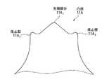
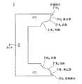
本発明におけるI型コア形状はI型形状そのものではなく、図2に示すように、棒状の本体11の各先端部の両側のほんの一部をほぼ直線状、大半を曲線形状にし、この部分と接合される第1、第2のC型コア2、3を対応形状に形成したことに特徴を有している。つまり、本体11の一方の先端がほぼ凸状に形成された形状をしている。この凸部11Aは先端に向かって狭くなるように形成されている。さらに、詳しくは図3に示すように、その凸部11Aの先端部分11A1が湾曲している。凸部11Aの両側の根本部分には、略三角形状の係止部11A2、11A3が形成されている。係止部11A2は第1のC型コア2を係り止めるものであり、係止部11A3は第2のC型コア3を係り止めるものである。これらの係止部11A2、11A3の先端も湾曲している。おなじく、凸部11Aの内側の隅部分11A4、11A5は凹状に湾曲し、さらにその内側の凸部11Aの角部分11A6、11A7も湾曲している。なお、凸部11Aの先端部分を平坦状にしても良い。In the present invention, the I-shaped core shape is not the I-shaped shape itself, but, as shown in FIG. 2, only a part of both ends of each end of the rod-shaped
このように、本体11の一方の先端は曲線形状をしている。同様に、本体11の他方の先端も曲線形状をしている。つまり、他方の先端の凸部11B、先端部分11B1、係止部11B2、11B3、隅部分11B4、11B5、および角部分11B6、11B7が、一方の先端の凸部11A、先端部分11A1、係止部11A2、11A3、隅部分11A4、11A5、および角部分11A6、11A7にそれぞれ対応している。Thus, one tip of the
本実施形態では、本体11の各先端部の両側を、それぞれ逆向きの円弧を結合し全体としてほぼS字状をなす曲線形状にすることにより、I型コア1が第1のC型コア2および第2のC型コア3と接触する部分である接合部の接触面積を大きくすることができる。 In the present embodiment, the I-
第1のC型コア2の両先端は、図4に示すように、I型コア1の両先端と嵌合する形状に形成されている。つまり、詳しくは図5に示すように、第1のC型コア2の先端部分21A1がI型コア1の先端部分11A1と嵌合する突部状の形状であり、先端部分21A1の内側に位置する第1のC型コア2の凹状の係止部21A2が、図1、図3等に示すI型コア1の突部状の係止部11A2と嵌合する形状である。第1のC型コア2の係止部21A2とI型コア1の係止部11A2とにより、2つのコア同士の機械的嵌合を行う。つまり、I型コア1の係止部11A2は爪形状の構造で第1のC型コア2の係止部21A2に圧入する方法と、これら2つの係止部を先端で溶接する方法との2通りの方法を可能にする。これらの係止部により、接合部の接合を強固にすることが可能となる。As shown in FIG. 4, both ends of the first C-
また、係止部21A2より内側の第1のC型コア2の湾曲した凸部分21A3が対応して形成されたI型コア1の隅部分11A4と嵌合する形状であり、第1のC型コア2の湾曲した凹部分21A4がI型コア1の角部分11A6と嵌合する形状である。Further, a shape of the convex portion 21A3 which curved engaging portion 21A2 than the first inner C-
おなじく、第1のC型コア2の先端部分21B1がI型コア1の先端部分11B1と嵌合する形状であり、第1のC型コア2の凹状の係止部21B2がI型コア1の係止部11B2と嵌合する形状である。Onajiku a shape that the distal end portion 21B1 of the first C-
また、第1のC型コア2の湾曲した凸部分21B3がI型コア1の隅部分11B4と嵌合する形状であり、第1のC型コア2の湾曲した凹部分21B4がI型コア1の角部分11B6と嵌合する形状である。Further, the curved convex portion 21B3 of the first C-
第2のC型コア3は第1のC型コア2と同様であるので、その詳細な説明を省略する。 Since the 2nd
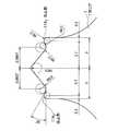
こうして、本実施形態によれば、第1のC型コア2および第2のC型コア3に対してI型コア1が嵌合されて、両者は一体化され、トランス用磁心が形成される。この場合、I型コア1のほぼ凸状の先端部分11A1、11B1の先端は前記C型コア2、3の外面から外部に突出しない寸法になっている。また、C型コア2、3と非接触とし、嵌合しやすいようにしている。隙間がないと若干の寸法誤差があっても嵌合させづらく組立性が悪いが、本発明ではそのようなことはない。なお、I型コア1の凸部11Aに対する各寸法、隅部分11A4、11A5、11B4、11B5を円弧で形成した場合の半径R、角部分11A6、11A7、11B6、11B7を円弧で形成した場合の半径Rは図6に示すような値が適切である。つまり、凸部11Aの幅を値Aとし、I型コア1の幅を値Bとする。幅Aはコアサイズによって5〜10[mm]まで可変する値、幅Bはコアサイズから決定される値、距離Cはコアサイズによって1.5〜3[mm]まで可変する値である。Thus, according to the present embodiment, the I-
これらの幅A、Bにより、コアサイズごとに求められる半径Rの大きさRmaxは、
Rmax=(B−A)/4
で与えられ、第1のC型コア2および第2のC型コア3の幅Eは、
E=B/2
で与えられる。そして、前記の式から大きさRmaxを割り出し、仮の曲線の中心とする。I型コア1の中心線から斜めに引かれた直線長Dを最短距離とした場合、
大きさRmaxで割り出した曲線長の範囲は直線長D×1.01〜D×2.15倍とする。さらに、I型コア1の凸部11Aは先端に向かって狭くなるように形成されている。なお、係止部11A2および係止部11A3の先端から第1のC型コア2および第2のC型コア3の端面までの距離を値Cとする。With these widths A and B, the size Rmax of the radius R required for each core size is
Rmax = (B−A) / 4
The width E of the first C-
E = B / 2
Given in. Then, the size Rmax is determined from the above formula and is set as the center of the temporary curve. When the straight line length D obliquely drawn from the center line of the I-
The range of the curve length determined by the size Rmax is a straight line length D × 1.01 to D × 2.15 times. Further, the
こうして、本実施形態によれば、I型コア1の凸部11Aの先端部分11A1の両側部とこれと対応するC型コア2の先端部分21A1をほぼ直線状にし、第1のC型コア2および第2のC型コア3とI型コア1との他の接合部を曲線で形成し、大半を曲線で接合させたので、I型コア1と第1のC型コア2との接触面積と、I型コア1と第2のC型コア3との接触面積とを、従来の技術(特許文献1)に比べて大きくすることができ、接合部での磁気抵抗を小さくすることができる。この結果、接合部での磁束の流れが良くなり、高効率なトランス、つまり低漏洩磁束、低振動、低発熱、低損失なトランスを実現することができる。特に、磁化力が小さくなるので、振動を抑制することができ、唸りの発生も抑えることができる。また、低漏洩磁束により、SR、HPBといった防磁対策も不要になり、シンプルで作りやすいトランスを実現することができる。Thus, according to this embodiment, the substantially straight tip portion 21A1 of the C-shaped
また、第1のC型コア2および第2のC型コア3とI型コア1との接合部の曲線形状を円弧とした場合には、第1のC型コア2および第2のC型コア3とI型コア1との接合部の加工を容易にすることができる。 Further, when the curved shape of the joint portion between the first C-
本実施例では、本実施形態によるトランス用磁心のI型コア1の先端、つまり、図3に示される各部分の大きさを図7に示されるようにしている。また、本実施例では、第1のC型コア2の先端(図5)および第2のC型コア3の先端の大きさを図8に示されるようにしている。本実施例では、I型コア1の係止部11A2、11A3の湾曲が円弧で形成され、その半径が値R0.3である。また、この係止部11A2に係り止められる、第1のC型コア2の係止部21A2の湾曲が円弧で形成され、その半径が値R0.25である。第2のC型コア3も同様である。In this example, the size of the tip of the I-
つまり、本実施例では、I型コア1の係止部11A2、11A3と第1のC型コア2の係止部21A2および第2のC型コア3の係止部の大きさを異なるようにしている。つまり、2つの係止部が略嵌合する場合でも、本発明の範囲内である。That is, in the present embodiment, the sizes of the locking
本実施例では、I型コア1の角部分と隅部分との半径をR3.0とした場合について説明する。図9は本実施例によるトランス用磁心の磁束密度分布図である。なお、図9および以下の図では、I型コア1と第2のC型コア3との嵌合の一部分を例としているが、他の嵌合部分も同様である。また、図9および以下の図では、領域が青色に近づく程、磁束が疎であることを示し、赤色に近づく程、磁束が密であることを示している。図9の矢印P1で示すように、I型コア1と第2のC型コア3との嵌合時の特性の維持(低磁気抵抗化等)とコア同士の機械的嵌合の目的で、先端を中心線で交差するとともに、幅1.5〜3.0[mm]のロック機構を設けている。
In the present embodiment, the case where the radius between the corner portion and the corner portion of the I-
また、矢印P2で示すように、磁束の集中が若干あるものの、全体として磁束が疎になる領域が発生している。 Further, as indicated by an arrow P2, there is a region where the magnetic flux is sparse as a whole although the magnetic flux is slightly concentrated.
図9の磁束線の様子を図10に示す。図10の矢印P11に示すように、磁束が有効にコアの磁路を渡っている。また、半径R3.0では、矢印P12、P13に示すように、若干磁束の集中する部分が発生している。 FIG. 10 shows the state of the magnetic flux lines in FIG. As indicated by an arrow P11 in FIG. 10, the magnetic flux effectively crosses the magnetic path of the core. Further, at the radius R3.0, as shown by arrows P12 and P13, a portion where the magnetic flux is slightly concentrated is generated.
図9の外部空間の磁束密度分布を図11に示す。図11の矢印P21に示すように、I型コア1の先端の部分で漏洩磁束が若干大きくなっている。 FIG. 11 shows the magnetic flux density distribution in the external space of FIG. As indicated by an arrow P21 in FIG. 11, the leakage magnetic flux is slightly increased at the tip of the I-
本実施例では、I型コア1の角部分と隅部分との半径をR5.0とした場合について説明する。図12は本実施例によるトランス用磁心の磁束密度分布図である。図12の矢印P31に示すように、I型コア1の先端の形状は実施例2と同じであるが、矢印P32に示すように、半径を大きくすると、実施例2に比べて若干集中していた磁束密度が無くなり、磁路全体に理想的な、緑色の磁束密度領域が増加している。また、半径を大きくすると、図13の矢印P41に示すように、実施例2に比べてI型コア1の先端の部分で漏洩磁束が減少している。 In this embodiment, a case where the radius between the corner portion and the corner portion of the I-
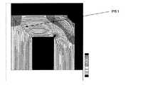
一方、図14の矢印P51に示すように、I型コアの先端が三角形状の従来技術(特許文献1)によれば、磁束密度分布は黄色の領域が多く、本実施例に比べると、磁束分布が全体で高くなっている。また、図15の矢印P61に示すように、従来技術は漏洩磁束も本実施例に比べて高くなっている。これは、従来技術に比べて、本実施例は接合部の長さが11.5[%]長いため、磁路が広がったことに起因する。 On the other hand, as shown by an arrow P51 in FIG. 14, according to the prior art (Patent Document 1) in which the tip of the I-type core has a triangular shape, the magnetic flux density distribution has many yellow regions. The distribution is high overall. Further, as shown by an arrow P61 in FIG. 15, the leakage flux in the conventional technique is higher than that in the present embodiment. This is due to the fact that the magnetic path is widened because the length of the joint in this example is 11.5 [%] longer than in the prior art.
以上、本発明の実施形態および実施例を詳述してきたが、具体的な構成は本実施形態および各実施例に限られるものではなく、本発明の要旨を逸脱しない範囲の設計の変更等があっても、本発明に含まれる。たとえば、トランス用磁心について説明したが、リアクターに適用することも可能である。 Although the embodiments and examples of the present invention have been described in detail above, the specific configuration is not limited to the embodiments and examples, and design changes and the like within a scope not departing from the gist of the present invention are possible. Even if it exists, it is included in this invention. For example, the transformer magnetic core has been described, but it can also be applied to a reactor.
1 I型コア
11 本体
11A、11B 凸部
11A1、11B1 先端部分
11A2、11A3、11B2、11B3 係止部
11A4、11A5、11B4、11B5 隅部分
11A6、11A7、11B6、11B7 角部分
2 第1のC型コア
21A1 先端部分
21A2 係止部
21A3 凸部分
21A4 凹部分
3 第2のC型コア
4 カシメ1 I-shaped
Claims (4)
Translated fromJapanese前記I型コア(1)の各先端部の両側部分とこれと対向する前記C型コア(2、3)の対向部分の形状の一部をほぼ直線状、大半を曲線との組み合わせで形成し曲線形状により両者の接合面積を大にし、かつ前記I型コア(1)の先端部分(11A1、11B1)をほぼ凸形の形状にし、その先端形状を弧状または平坦とし、この先端は前記C型コア(2、3)の外面から外部に突出せず、かつC型コア(2、3)と非接触としたことを特徴とするトランス用磁心。In a transformer magnetic core comprising an I-type core (1) and two C-type cores (2, 3) respectively disposed on both sides of the I-type core (1),
A part of the shapeof both ends of each tip of the I-type core (1) and the opposite part of the C-type core (2, 3) facing the I-core is formed by a combination of a substantially straight line and a majority of the curve. The joint area between the two is increased by the curved shape, and the tip portion (11A1, 11B1) of theI-type core (1) is formed in a substantially convex shape, and the tip shape is made arcuate or flat. A transformer core characterizedin that itdoes not protrude outward from the outer surface of the C-type core (2, 3) and is not in contact with the C-type core (2, 3) .
Priority Applications (6)
| Application Number | Priority Date | Filing Date | Title |
|---|---|---|---|
| JP2005012835AJP4447475B2 (en) | 2005-01-20 | 2005-01-20 | Magnetic core for transformer |
| CN200680002369XACN101103421B (en) | 2005-01-20 | 2006-01-19 | Magnetic core for transformer |
| DE112006000239TDE112006000239T5 (en) | 2005-01-20 | 2006-01-19 | Magnetic core for transformer |
| PCT/JP2006/301175WO2006078060A1 (en) | 2005-01-20 | 2006-01-19 | Magnetic core for transformer |
| KR1020077016567AKR100891760B1 (en) | 2005-01-20 | 2006-01-19 | Magnetic core for transformer |
| US11/879,471US20070279179A1 (en) | 2005-01-20 | 2007-07-17 | Magnetic core for transformer |
Applications Claiming Priority (1)
| Application Number | Priority Date | Filing Date | Title |
|---|---|---|---|
| JP2005012835AJP4447475B2 (en) | 2005-01-20 | 2005-01-20 | Magnetic core for transformer |
Publications (2)
| Publication Number | Publication Date |
|---|---|
| JP2006202967A JP2006202967A (en) | 2006-08-03 |
| JP4447475B2true JP4447475B2 (en) | 2010-04-07 |
Family
ID=36692425
Family Applications (1)
| Application Number | Title | Priority Date | Filing Date |
|---|---|---|---|
| JP2005012835AExpired - Fee RelatedJP4447475B2 (en) | 2005-01-20 | 2005-01-20 | Magnetic core for transformer |
Country Status (6)
| Country | Link |
|---|---|
| US (1) | US20070279179A1 (en) |
| JP (1) | JP4447475B2 (en) |
| KR (1) | KR100891760B1 (en) |
| CN (1) | CN101103421B (en) |
| DE (1) | DE112006000239T5 (en) |
| WO (1) | WO2006078060A1 (en) |
Families Citing this family (2)
| Publication number | Priority date | Publication date | Assignee | Title |
|---|---|---|---|---|
| JP2010258365A (en)* | 2009-04-28 | 2010-11-11 | Nippon Steel Corp | Iron core for power equipment |
| CN102208258B (en)* | 2011-03-03 | 2012-10-10 | 厦门宏美电子有限公司 | Silicon-steel sheet structure of current transformer and current transformer |
Family Cites Families (7)
| Publication number | Priority date | Publication date | Assignee | Title |
|---|---|---|---|---|
| DE2658665C2 (en)* | 1976-12-23 | 1987-01-15 | Sawatzky, Wilfried E., North Balwyn | Core sheet for a shell core |
| JPS57132308A (en) | 1981-02-09 | 1982-08-16 | Honda Motor Co Ltd | Iron core for closed magnetic path type ignition coil |
| JPS6376407A (en) | 1986-09-19 | 1988-04-06 | Tokyo Electric Co Ltd | electromagnetic equipment |
| JP2845075B2 (en)* | 1993-02-19 | 1999-01-13 | 松下電器産業株式会社 | Coil parts |
| US5861792A (en)* | 1993-02-19 | 1999-01-19 | Matsushita Electric Industrial Co., Ltd. | Coil component and method of stamping iron core used therefor |
| WO1994019811A1 (en)* | 1993-02-19 | 1994-09-01 | Matsushita Electric Industrial Co., Ltd. | Coil component and method of punching core used for the coil component |
| KR200367482Y1 (en)* | 2004-08-05 | 2004-11-10 | 주식회사 삼립전기 | Core of transformer |
- 2005
- 2005-01-20JPJP2005012835Apatent/JP4447475B2/ennot_activeExpired - Fee Related
- 2006
- 2006-01-19WOPCT/JP2006/301175patent/WO2006078060A1/enactiveApplication Filing
- 2006-01-19KRKR1020077016567Apatent/KR100891760B1/ennot_activeExpired - Fee Related
- 2006-01-19DEDE112006000239Tpatent/DE112006000239T5/ennot_activeCeased
- 2006-01-19CNCN200680002369XApatent/CN101103421B/ennot_activeExpired - Fee Related
- 2007
- 2007-07-17USUS11/879,471patent/US20070279179A1/ennot_activeAbandoned
Also Published As
| Publication number | Publication date |
|---|---|
| JP2006202967A (en) | 2006-08-03 |
| WO2006078060A1 (en) | 2006-07-27 |
| US20070279179A1 (en) | 2007-12-06 |
| CN101103421A (en) | 2008-01-09 |
| CN101103421B (en) | 2010-07-14 |
| KR20070091024A (en) | 2007-09-06 |
| KR100891760B1 (en) | 2009-04-07 |
| DE112006000239T5 (en) | 2008-06-26 |
Similar Documents
| Publication | Publication Date | Title |
|---|---|---|
| US8570133B2 (en) | Transformer | |
| US20060238288A1 (en) | Magnetic core for electromagnetic apparatus and electromagnetic apparatus provided with magnetic core for electromagnetic apparatus | |
| JP5215761B2 (en) | Trance | |
| JPH0566934U (en) | Core for coil device of switching power supply | |
| JP6283976B2 (en) | Common mode choke | |
| JP4447475B2 (en) | Magnetic core for transformer | |
| JP6143076B2 (en) | Superconducting rotating electrical machine stator | |
| JP2009141117A (en) | Reactor | |
| JP2008159832A (en) | Reactor | |
| JP2009177019A (en) | Transformer | |
| JP6237586B2 (en) | Induction equipment | |
| JP2007110118A (en) | Magnetic circuit for ignition coil or transformer | |
| JP4249594B2 (en) | Transformers and transformer cores | |
| KR200367482Y1 (en) | Core of transformer | |
| CN103065768B (en) | Magnetic core and induction installation | |
| JP6010491B2 (en) | Resonator and wireless power transmission device | |
| JP2002208519A (en) | Three-phase reactor sheet core and block core thereof | |
| JP2004031647A (en) | Inverter transformer | |
| JP2006351959A (en) | Reactor | |
| JP4634662B2 (en) | Non-contact transmission coupler | |
| JP4704670B2 (en) | Amorphous winding core transformer | |
| JP2010225901A (en) | Reactor | |
| JP2005223210A (en) | Ignition coil | |
| JP2014063796A (en) | Reactor | |
| JP2005150413A (en) | Power core |
Legal Events
| Date | Code | Title | Description |
|---|---|---|---|
| A621 | Written request for application examination | Free format text:JAPANESE INTERMEDIATE CODE: A621 Effective date:20070323 | |
| A131 | Notification of reasons for refusal | Free format text:JAPANESE INTERMEDIATE CODE: A131 Effective date:20091104 | |
| A521 | Request for written amendment filed | Free format text:JAPANESE INTERMEDIATE CODE: A523 Effective date:20091221 | |
| TRDD | Decision of grant or rejection written | ||
| A01 | Written decision to grant a patent or to grant a registration (utility model) | Free format text:JAPANESE INTERMEDIATE CODE: A01 Effective date:20100119 | |
| A01 | Written decision to grant a patent or to grant a registration (utility model) | Free format text:JAPANESE INTERMEDIATE CODE: A01 | |
| A61 | First payment of annual fees (during grant procedure) | Free format text:JAPANESE INTERMEDIATE CODE: A61 Effective date:20100120 | |
| FPAY | Renewal fee payment (event date is renewal date of database) | Free format text:PAYMENT UNTIL: 20130129 Year of fee payment:3 | |
| R150 | Certificate of patent or registration of utility model | Free format text:JAPANESE INTERMEDIATE CODE: R150 | |
| LAPS | Cancellation because of no payment of annual fees |