Movatterモバイル変換


[0]ホーム

URL:


JP4446045B2 - Object internal treatment device and object internal treatment system - Google Patents

Object internal treatment device and object internal treatment system
Download PDF

Info

Publication number
JP4446045B2
JP4446045B2JP2004011954AJP2004011954AJP4446045B2JP 4446045 B2JP4446045 B2JP 4446045B2JP 2004011954 AJP2004011954 AJP 2004011954AJP 2004011954 AJP2004011954 AJP 2004011954AJP 4446045 B2JP4446045 B2JP 4446045B2
Authority
JP
Japan
Prior art keywords
treatment
main body
endoscope
treatment tool
observation
Prior art date
Legal status (The legal status is an assumption and is not a legal conclusion. Google has not performed a legal analysis and makes no representation as to the accuracy of the status listed.)
Expired - Lifetime
Application number
JP2004011954A
Other languages
Japanese (ja)
Other versions
JP2005204728A (en
Inventor
邦利 池田
健一 大原
忠生 垣添
寿光 小林
Current Assignee (The listed assignees may be inaccurate. Google has not performed a legal analysis and makes no representation or warranty as to the accuracy of the list.)
Hoya Corp
National Cancer Center Japan
Original Assignee
Hoya Corp
National Cancer Center Japan
Priority date (The priority date is an assumption and is not a legal conclusion. Google has not performed a legal analysis and makes no representation as to the accuracy of the date listed.)
Filing date
Publication date
Application filed by Hoya Corp, National Cancer Center JapanfiledCriticalHoya Corp
Priority to JP2004011954ApriorityCriticalpatent/JP4446045B2/en
Priority to DE112004001398Tprioritypatent/DE112004001398T5/en
Priority to PCT/JP2004/010539prioritypatent/WO2005009227A1/en
Priority to US10/566,204prioritypatent/US8753262B2/en
Publication of JP2005204728ApublicationCriticalpatent/JP2005204728A/en
Application grantedgrantedCritical
Publication of JP4446045B2publicationCriticalpatent/JP4446045B2/en
Anticipated expirationlegal-statusCritical
Expired - Lifetimelegal-statusCriticalCurrent

Links

Images

Landscapes

Description

Translated fromJapanese

本発明は、対象物内部の対象部位の切除等を行う対象物内部処置装置及び対象物内部処置システムに関し、とくに患者体内の病変部を治療するための装置及びシステムに関する。  The present invention relates to an object internal treatment apparatus and an object internal treatment system that perform excision of a target site inside the object, and more particularly to an apparatus and system for treating a lesion in a patient.

従来、患者体内の病変部の外科的治療は、切開した部分から患者体内へ導入した処置具を術者が直接操作して行っていた。また、近年では、切開部分から患者体内へ導入された処置具に術者が直接触れずに患者外部から遠隔操作する方法も考案されている。
特開2001−104333号公報
Conventionally, surgical treatment of a lesion in a patient has been performed by an operator directly operating a treatment tool introduced into the patient from an incised portion. In recent years, a method has also been devised in which a surgeon does not directly touch a treatment tool introduced into a patient from an incised portion and is remotely operated from outside the patient.
JP 2001-104333 A

上述の患者体内の病変部の外科的治療においては、内視鏡による観察画面が処置具によって隠れてしまうことがあるため、視野が狭くなり病変部およびその周辺が見えにくくなるおそれがある。  In the above-described surgical treatment of a lesion in a patient, an observation screen by an endoscope may be hidden by a treatment tool, so that the field of view is narrowed and the lesion and its surroundings may be difficult to see.

また、複数の処置具を患者体内へ導入した場合には処置具同士または処置具と内視鏡とが干渉しやすくなるため、処置具及び内視鏡を病変部まで到達させることができない場合がある。  In addition, when a plurality of treatment tools are introduced into a patient's body, the treatment tools or the treatment tool and the endoscope are likely to interfere with each other. Therefore, the treatment tool and the endoscope may not reach the lesioned part. is there.

上記問題点を解決するために、本発明の対象物内部処置装置においては、対象物内部に導入される可撓性を有する円筒状の本体部が、前記本体部の底面のうち前記対象物側に配置される底面の中央から前記本体部を貫通するように設けられ、対象部位を観察する内視鏡を挿入する中央孔部と、前記本体部の側面から前記本体部を貫通し、かつその出口側端部の軸線が前記中央孔部に対して前記対象物側に向かうにつれて該中央孔部から離れる方向に傾斜するように設けられ、前記対象部位を処置する処置具を挿入する複数の周辺孔部と、を備えることを特徴としている。In order to solve the above problems, in the object internal treatment device of the present invention, a flexible cylindrical main body introduced into the object is arranged on the object side of the bottom surface of the main body. provided to penetrate through the main body portion from the center of the bottom surface to be disposed in a central hole for inserting the endoscope to observe the target site,through the body portion from a side of the main bodyportion, and that A plurality of peripherals in which a treatment instrument for treating the target portion is inserted so thatthe axis of the outlet side end portion is inclined in a direction away from the central hole portion toward the object side with respect to the central hole portion. And a hole.

本発明の対象物内部処置システムにおいては、対象物内部に導入される可撓性を有する円筒状の本体部であって、前記本体部の底面のうち前記対象物側に配置される底面の中央から前記本体部を貫通するように設けられ、対象部位を観察する内視鏡を挿入する円形断面の中央孔部、および前記本体部の側面から前記本体部を貫通し、かつその出口側端部の軸線が前記中央孔部に対して前記対象物側に向かうにつれて該中央孔部から離れる方向に傾斜するように設けられ、前記対象部位を処置する処置具を挿入する複数の周辺孔部、を備える本体部と、前記対象物の外部において前記本体部を操作する本体部操作手段と、前記対象物の外部において前記内視鏡を操作する内視鏡操作手段と、前記対象物の外部において前記処置具を操作する処置具操作手段と、を備えることを特徴としている。In the object internal treatment system of the present invention, a flexible cylindrical main body introduced into the object, the center of the bottom surface disposed on the object side among the bottom surfaces of the main body A central hole portion having a circular cross section for insertion of an endoscope for observing a target site, and an end portion on the outlet side of the main body portion from the side surface of the main bodyportion. A plurality of peripheral hole portions into which a treatment instrument for treating the target portion is inserted so thatthe axis of the head is inclined in a direction away from the central hole portion toward the object side with respect to the central hole portion. A main body unit, a main body operation means for operating the main body part outside the object, an endoscope operation means for operating the endoscope outside the object, and the outside of the object. Treatment to operate the treatment tool It is characterized by comprising an operation means.

上記内視鏡は、対象部位を立体的に観察することができる立体視内視鏡とすることができる。  The endoscope can be a stereoscopic endoscope capable of observing a target portion in three dimensions.

上記処置具は、処置具の先端付近を観察可能な観察手段を有することが好ましい。  It is preferable that the treatment instrument has an observation unit capable of observing the vicinity of the distal end of the treatment instrument.

上記処置具は、処置具の先端付近を照明可能な照明手段を有することが好ましい。  It is preferable that the treatment instrument includes an illumination unit that can illuminate the vicinity of the distal end of the treatment instrument.

上記処置具は、観察手段の先端を洗浄可能な送気送水手段を有することが好ましい。  The treatment instrument preferably has an air / water supply means capable of cleaning the tip of the observation means.

上記内視鏡による画像を表示するための画像表示手段を備えるとよい。  Image display means for displaying an image by the endoscope may be provided.

上記本体部は湾曲自在な湾曲部を有することが好ましい。  The main body preferably has a bendable bending portion.

上記処置具は湾曲自在な湾曲部を有することが好ましい。  The treatment instrument preferably has a bendable bending portion.

本発明によると、円筒状の本体部の底面から内視鏡を延出させるとともに処置具を側面から延出させることとしているため、内視鏡による観察画面が処置具によって隠れてしまって、視野が狭くなり病変部およびその周辺が見えにくくなることが少なくなる。さらに、複数の処置具を患者体内へ導入する場合には内視鏡の観察視野の周囲側から処置具を病変部に到達させることが可能となるため、処置具同士または処置具と内視鏡とが干渉することが少なくなり、処置具及び内視鏡を病変部まで確実に到達させることができる。また、本体部内に処置具及び内視鏡を収容した状態で患者体内へ導入することができるので、複数の処置具を切開部分に同時に導入する場合であっても、切開の長さを大きくとらずに済む。  According to the present invention, since the endoscope is extended from the bottom surface of the cylindrical main body and the treatment tool is extended from the side surface, the observation screen by the endoscope is hidden by the treatment tool, and the visual field Becomes narrower and it is less likely that the lesion and its surroundings are difficult to see. Further, when a plurality of treatment tools are introduced into a patient body, the treatment tools can reach the lesion from the peripheral side of the observation field of the endoscope. And the treatment tool and the endoscope can surely reach the lesion. In addition, since the treatment tool and the endoscope can be introduced into the patient while being accommodated in the main body, even when a plurality of treatment tools are simultaneously introduced into the incision portion, the length of the incision is greatly increased. You do n’t have to.

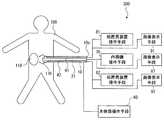
以下、本発明に係る実施形態を図1〜8を参照しつつ詳しく説明する。本実施形態に係る対象物内部処置装置200、対象物内部処置システム300(図8)は、対象物としての患者の体内の病変部(対象部位)の治療を行うためのものであって、中央孔部20及び周辺孔部30を備える本体部10を有し、対象物内部処置システム300はさらに本体部操作手段60、内視鏡操作手段70、及び、処置具操作手段81、82を有する。  Hereinafter, embodiments according to the present invention will be described in detail with reference to FIGS. The objectinternal treatment device 200 and the object internal treatment system 300 (FIG. 8) according to the present embodiment are for treating a lesion (target part) in a patient's body as an object, The objectinternal treatment system 300 includes a main body operation means 60, an endoscope operation means 70, and treatment instrument operation means 81 and 82.

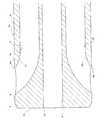
本体部10は、患者(対象物)の体内に導入される可撓性を有する円筒状部材で形成することができる。この本体部10は、図3に示すように、先端に行くほど外径が小さくなる円形断面を備える先端部11と、先端部11の後端面11aに固定された湾曲自在な湾曲部12とを備えている。本体部10は先端部11の先端から患者体内に導入され、病変部の位置に応じて体内の深部まで導入することができる。本体部10は、その後端部において接続された本体部操作手段60(図8)により、本体部10の患者体内への導入および導出のほか、湾曲部12の湾曲具合の調整を行うことができる。本体部操作手段60としては、例えば術者による手動操作、自動送出、巻取装置があり、これにより、本体部10は本体部操作手段60により外部から操作可能となる。  Themain body 10 can be formed of a flexible cylindrical member that is introduced into the body of a patient (object). As shown in FIG. 3, themain body 10 includes adistal end portion 11 having a circular cross section whose outer diameter decreases toward the distal end, and abendable bending portion 12 fixed to therear end surface 11 a of thedistal end portion 11. I have. Themain body 10 is introduced into the patient from the distal end of thedistal end 11, and can be introduced deep into the body depending on the position of the lesion. Themain body part 10 can adjust the bending state of thebending part 12 in addition to the introduction and derivation of themain body part 10 into the patient body by the main body operation means 60 (FIG. 8) connected at the rear end part. . Examples of the main body operation means 60 include manual operation by an operator, automatic transmission, and a winding device. Themain body section 10 can be operated from the outside by the main body operation means 60.

円筒状の本体部10は、その二つの底面のうち病変部110側に配置される底面(先端面)11bの中央から他方の底面(後端面)(不図示)へ向けて本体部10内を貫通する中央孔部20と、湾曲部12の側面12bから本体部10の後端面10c(図8)へ向けて本体部10内を貫通する周辺孔部30とを有している。中央孔部20には病変部(対象部位)を観察する内視鏡21が挿通され、内視鏡21は出口20bから病変部110側へ延出される。周辺孔部30は、中央孔部20の中心20aに関して等角度間隔(この例では180度間隔)に配置された二つの円形の孔部31、32から構成される。孔部31、32の出口側端部31b、32bの軸線は中央孔部20に対して傾斜しており、孔部31、32には病変部を処置する処置具41、42がそれぞれ挿通され、処置具41、42は出口31a、32aから外部へ延出される。出口31aと先端面11bとの距離は出口32aと先端面11bとの距離に等しくされている。出口31a及び出口32aの内径が同一であると、処置の内容、手順に応じて処置具41、42を入れ替えることができるため好ましい。また、処置具41、42を所望の角度にするために、出口31a、32aの内径を処置具41、42の外径より大きくすることが望ましい。The cylindricalmain body 10 is formed in themain body 10 from the center of the bottom surface (front end surface) 11b arranged on thelesioned part 110 side to the other bottom surface (rear end surface) (not shown) of the two bottom surfaces. Acentral hole portion 20 that penetrates and aperipheral hole portion 30 that penetrates through the inside of themain body portion 10 from theside surface 12b of thebending portion 12 toward therear end surface 10c (FIG. 8) of themain body portion 10 are provided. Anendoscope 21 for observing a lesioned part (target site) is inserted into thecentral hole 20, and theendoscope 21 extends from theoutlet 20b to thelesioned part 110 side. Theperipheral hole 30 is composed of twocircular holes 31 and 32 arranged at equal angular intervals (180 degrees in this example) with respect to thecenter 20a of thecentral hole 20.The axial lines of the outletside end portions 31b and 32b of thehole portions 31 and 32are inclined with respect to thecentral hole portion 20, and thetreatment tools 41 and 42 for treating the lesioned portion are inserted intothehole portions 31 and 32, respectively. Thetreatment tools 41 and 42 are extended to the outside from theoutlets 31a and 32a. The distance between theoutlet 31a and thetip surface 11b is equal to the distance between theoutlet 32a and thetip surface 11b. It is preferable that the inner diameters of theoutlet 31a and theoutlet 32a are the same because thetreatment tools 41 and 42 can be replaced according to the content and procedure of the treatment. In order to make thetreatment tools 41 and 42 have a desired angle, it is desirable that the inner diameters of theoutlets 31a and 32a be larger than the outer diameters of thetreatment tools 41 and 42.

孔部31及び孔部32を備えた本体部10の形成は既存の手法により行うことができる。例えば、孔部31及び孔部32と同一形状の円筒状部分を備えた型に熱溶融性の樹脂を流し込んで冷却固化することによって、孔部31及び孔部32を備えた本体部10を形成することができる。このように孔部31及び孔部32を形成することによって、本体部10内で内視鏡及び二つの処置具が絡んでしまって、または干渉し合って操作が困難となるおそれがなくなる。以上のように形成される本体部10は、例えば、本体部10の外径が5cmであるとき、孔部31、32、それぞれの内径を1.2cmとすることができる。また、先端部11及び中央孔部20は断面が円形でなくてもよい。  Formation of themain body part 10 provided with thehole part 31 and thehole part 32 can be performed by the existing method. For example, themain body 10 having thehole 31 and thehole 32 is formed by pouring a heat-meltable resin into a mold having a cylindrical portion having the same shape as thehole 31 and thehole 32 and solidifying by cooling. can do. By forming thehole portion 31 and thehole portion 32 in this way, there is no possibility that the endoscope and the two treatment tools are entangled or interfere with each other in themain body portion 10 and the operation becomes difficult. For example, when the outer diameter of themain body 10 is 5 cm, themain body 10 formed as described above can have the inner diameters of theholes 31 and 32 and 1.2 cm, respectively. Further, thedistal end portion 11 and thecentral hole portion 20 may not have a circular cross section.

立体視内視鏡21は、図3に示すように、湾曲可能な円筒状の本体部21aに、病変部を立体的に観察するための二つの観察光学系21b、21cと、病変部を照らすための照明光学系21d、21eと、観察光学系21b、21cの表面の曇りの除去、洗浄のための送水、および、患者体内への送気を行うための送気送水系21f、21gと、が挿通固定されている。このように、立体視内視鏡21を採用したことにより病変部およびその周辺を立体的に観察することができるため、治療を的確かつスムーズに行うことができる。また、図8に示すように、この立体視内視鏡21はその後端部において、本体部21aの導入、導出、観察光学系21b、21cの焦点、視野、ズーミングの調節、照明光学系21d、21eの明るさ、方向、角度の調整、観察光学系21b、21cの表面の曇りの除去、洗浄のための送水、ならびに、患者体内への送気などの操作を行うための内視鏡操作手段70に接続されている。これにより、立体視内視鏡21は内視鏡操作手段70により外部から操作可能となる。また、観察光学系21b、21cは、立体視内視鏡21の後端部においてこれらによる病変部およびその周辺の画像を立体的に表示可能な画像表示手段87に接続されている。なお、治療の内容等によっては、観察光学系を一つとすることもできる。  As shown in FIG. 3, thestereoscopic endoscope 21 illuminates a bendable cylindricalmain body portion 21 a with two observationoptical systems 21 b and 21 c for stereoscopically observing the lesioned portion. Illuminationoptical systems 21d and 21e for observation, removal of fogging of the surfaces of the observationoptical systems 21b and 21c, water supply for cleaning, and air supply andwater supply systems 21f and 21g for supplying air into the patient body, Is inserted and fixed. As described above, the adoption of thestereoscopic endoscope 21 enables the lesioned part and the periphery thereof to be stereoscopically observed, so that the treatment can be performed accurately and smoothly. In addition, as shown in FIG. 8, thestereoscopic endoscope 21 has, at its rear end, the introduction and derivation of themain body 21a, the focus of the observationoptical systems 21b and 21c, the visual field, the adjustment of zooming, the illuminationoptical system 21d, Endoscopic operation means for performing operations such as adjustment of brightness, direction and angle of 21e, removal of fogging of the surfaces of observationoptical systems 21b and 21c, water supply for cleaning, and air supply into the patient'sbody 70. Thereby, thestereoscopic endoscope 21 can be operated from the outside by the endoscope operating means 70. In addition, the observationoptical systems 21b and 21c are connected to an image display means 87 capable of stereoscopically displaying the lesion area and its surrounding image at the rear end of thestereoscopic endoscope 21. Note that one observation optical system may be used depending on the content of treatment.

処置具41は、例えば処置具42により周辺を把持された病変部を切除するためのものであって、図3に示すように、湾曲可能な円筒状の本体部41aに、物体を切除可能な鋏鉗子41b、鋏鉗子41bの先端付近を観察するための観察光学系(観察手段)41cと、鋏鉗子41b先端付近を照らすための照明光学系(照明手段)41d、41eと、観察光学系41cの表面の曇りの除去、洗浄のための送水、および、患者体内への送気を行うための送気送水系(送気送水手段)41f、41gと、が挿通固定されている。図8に示すように、処置具41はその後端において、本体部41aの導入、導出、湾曲、鋏鉗子41bによる切除動作の制御、観察光学系41cの焦点、視野、ズーミングの調節、照明光学系41d、41eの明るさ、方向、角度の調整、観察光学系41cの表面の曇りの除去、洗浄のための送水、ならびに、患者体内への送気などの操作を行うための処置具操作手段81に接続されている。これにより、この処置具操作手段81により外部から操作可能である。また、観察光学系41cは、処置具41の後端部において、観察光学系41cによる鋏鉗子41b先端付近の画像を表示可能な画像表示手段91に接続されている。なお、観察光学系を二つにして鋏鉗子41b先端付近を立体的に観察できるようにすることもできる。あるいは、赤外光観察、蛍光観察、ズーム観察、超音波観察、共焦点観察、オプティカル・コヒーレント・トモグラフィ観察(OCT)などを行うようにすることもできる。  Thetreatment tool 41 is for excising a lesioned part gripped by thetreatment tool 42, for example, and as shown in FIG. 3, an object can be excised in a bendable cylindricalmain body 41a. Acupuncture forceps 41b, an observation optical system (observation means) 41c for observing the vicinity of the front end of theacupuncture forceps 41b, illumination optical systems (illumination means) 41d, 41e for illuminating the vicinity of the front end of theacupuncture forceps 41b, and an observationoptical system 41c An air supply / water supply system (air supply / water supply means) 41f and 41g for removing cloudiness on the surface, supplying water for cleaning, and supplying air into the patient's body are inserted and fixed. As shown in FIG. 8, at the rear end of thetreatment instrument 41, themain body portion 41a is introduced, led out, bent, the excision operation is controlled by thescissors forceps 41b, the focus of the observationoptical system 41c, the visual field, zooming adjustment, and the illumination optical system. Treatment tool operation means 81 for adjusting the brightness, direction, and angle of 41d and 41e, removing fogging on the surface of the observationoptical system 41c, supplying water for cleaning, and supplying air into the patient's body It is connected to the. Accordingly, the treatment tool operation means 81 can be operated from the outside. The observationoptical system 41c is connected to the image display means 91 that can display an image near the tip of thescissors forceps 41b by the observationoptical system 41c at the rear end portion of thetreatment instrument 41. It should be noted that two observation optical systems can be provided so that the vicinity of the tip of thescissors forceps 41b can be observed three-dimensionally. Alternatively, infrared light observation, fluorescence observation, zoom observation, ultrasonic observation, confocal observation, optical coherent tomography observation (OCT), and the like can be performed.

処置具42は、例えば病変部の周辺を把持して処置具41による切開の用に供するためのものであって、図3に示すように、湾曲可能な円筒状の本体部42aに、物体を把持可能な把持鉗子42b、把持鉗子42b先端付近を観察するための観察光学系(観察手段)42cと、把持鉗子42b先端付近を照らすための照明光学系(照明手段)42d、42eと、観察光学系42cの表面の曇りの除去、洗浄のための送水、および、患者体内への送気を行うための送気送水系(送気送水手段)42f、42gと、が挿通固定されている。図8に示すように、処置具42はその後端において、本体部42aの導入、導出、湾曲、把持鉗子42bによる把持動作の制御、観察光学系42cの焦点、視野、ズーミングの調節、照明光学系42d、42eの明るさ、方向、角度の調整、観察光学系42cの表面の曇りの除去、洗浄のための送水、ならびに、患者体内への送気などの操作を行うための処置具操作手段82に接続されている。このため、この処置具操作手段82により外部から操作可能である。また、観察光学系42cは、処置具42の後端部において、観察光学系42cによる把持鉗子42b先端付近の画像を表示可能な画像表示手段92に接続されている。なお、観察光学系を二つにして把持鉗子42b先端付近を立体的に観察できるようにすることもできる。あるいは、赤外光観察、蛍光観察、ズーム観察、超音波観察、共焦点観察、オプティカル・コヒーレント・トモグラフィ観察(OCT)などを行うようにすることもできる。  For example, thetreatment tool 42 is used for grasping the periphery of a lesioned part and using it for incision by thetreatment tool 41. As shown in FIG. 3, an object is placed on a bendable cylindricalmain body part 42a. Grippingforceps 42b, an observation optical system (observation means) 42c for observing the vicinity of the distal end of the graspingforceps 42b, illumination optical systems (illumination means) 42d and 42e for illuminating the vicinity of the distal end of the graspingforceps 42b, and observation optics Air supply / water supply systems (air supply / water supply means) 42f and 42g for removing cloudiness on the surface of thesystem 42c, supplying water for cleaning, and supplying air to the patient's body are inserted and fixed. As shown in FIG. 8, at the rear end of thetreatment instrument 42, themain body 42a is introduced, led out, bent, the gripping force is controlled by the graspingforceps 42b, the focus, field of view, zooming adjustment of the observationoptical system 42c, and the illumination optical system. Treatment instrument operation means 82 for performing operations such as adjustment of the brightness, direction, and angle of 42d and 42e, removal of fogging of the surface of the observationoptical system 42c, water supply for cleaning, and air supply into the patient. It is connected to the. For this reason, the treatment tool operation means 82 can be operated from the outside. In addition, the observationoptical system 42c is connected to an image display means 92 that can display an image near the tip of the graspingforceps 42b by the observationoptical system 42c at the rear end portion of thetreatment instrument 42. It should be noted that two observation optical systems can be provided so that the vicinity of the tip of the graspingforceps 42b can be observed in three dimensions. Alternatively, infrared light observation, fluorescence observation, zoom observation, ultrasonic observation, confocal observation, optical coherent tomography observation (OCT), and the like can be performed.

なお、処置具41、42は、治療順序、病変部の形状等に応じて孔部31、32のいずれに挿入してもよい。また、処置具41及び処置具42以外の処置具も孔部31、32に挿入可能である。ここで、例えば、孔部31、32それぞれの内径を1.2cmとしたとき、処置具41、42それぞれの外径を1cmとすることができる。    Thetreatment tools 41 and 42 may be inserted into any of theholes 31 and 32 according to the treatment order, the shape of the lesioned part, and the like. In addition, treatment tools other than thetreatment tool 41 and thetreatment tool 42 can be inserted into theholes 31 and 32. Here, for example, when the inner diameter of each of theholes 31 and 32 is 1.2 cm, the outer diameter of each of thetreatment instruments 41 and 42 can be 1 cm.

以上のように、立体視内視鏡21を先端面11bから延出させ、かつ、処置具41及び処置具42を側面12bから延出させることによって、立体視内視鏡21、処置具41及び処置具42が患者体内100において互いに絡みあうことを少なくすることができる。このため、立体視内視鏡21、処置具41及び処置具42を所望の位置に配置することが容易になる。さらに、図4に示すように、立体視内視鏡21の観察視野22において処置具41及び処置具42が側方から病変部110に到達することとなるため、処置具41及び処置具42によって邪魔されることがなくなり、術者が見ることのできる範囲が広くなる。  As described above, by extending thestereoscopic endoscope 21 from thedistal end surface 11b and extending thetreatment tool 41 and thetreatment tool 42 from theside surface 12b, thestereoscopic endoscope 21, thetreatment tool 41, and It is possible to reduce thetreatment tool 42 from being entangled with each other in thepatient body 100. For this reason, it becomes easy to arrange | position thestereoscopic endoscope 21, thetreatment tool 41, and thetreatment tool 42 in a desired position. Furthermore, as shown in FIG. 4, since thetreatment tool 41 and thetreatment tool 42 reach thelesioned part 110 from the side in the observation visual field 22 of thestereoscopic endoscope 21, thetreatment tool 41 and thetreatment tool 42 The range that the surgeon can see is widened without being disturbed.

周辺孔部30を構成する孔部の数は任意に設定することができる。例えば、図5〜7に示すように、周辺孔部30を5つの孔部からなるとすることもできる。この例においては、周辺孔部30は5つの孔部31、32、33、34、35からなる。孔部31、32、33、34および35は、中央孔部20の中心20aに関して等角度間隔(72度間隔)に配置され、かつその出口側端部31b、32b、33b、34b、35b、36bの軸線は中央孔部20に対して傾斜しており、本体部10内を貫通して側面12bに設けた円形の出口31a、32a、33a、34a、35aにそれぞれ至っている。出口31a、32a、33a、34a、35aそれぞれと先端面11bとの距離は等しくされている。孔部31、32、33、34、35には、それぞれ、可撓性の長尺形状からなる上述の処置具42、41、並びに処置具43、44、及び45が抜き差し可能に挿入、貫通される。The number of holes constituting theperipheral hole 30 can be arbitrarily set. For example, as shown in FIGS. 5 to 7, theperipheral hole 30 may be composed of five holes. In this example, theperipheral hole portion 30 includes fivehole portions 31, 32, 33, 34, and 35. Theholes 31, 32, 33, 34, and 35 are arranged at equal angular intervals (72-degree intervals) with respect to thecenter 20a of thecentral hole 20,and theoutlet end portions 31b, 32b, 33b, 34b, 35b, and 36b are arranged.These axes are inclined with respect to thecentral hole portion 20, and pass through the inside ofthemain body portion 10 to thecircular outlets 31a, 32a, 33a, 34a, and 35a provided on theside surface 12b. The distances between theoutlets 31a, 32a, 33a, 34a, and 35a and thetip surface 11b are equal. Thetreatment tools 42 and 41 and thetreatment tools 43, 44, and 45 having a flexible long shape are inserted into and penetrated into theholes 31, 32, 33, 34, and 35, respectively. The

処置具43は、病変部およびその周辺を洗浄するための送水、および、病変部およびその周辺の血液、洗浄水などの液体の吸引を行うためのものであって、図7に示すように、湾曲可能な円筒状の本体部43aに、病変部およびその周辺を洗浄するときには水を送水し、病変部およびその周辺の血液、洗浄水などの液体を吸引するときには外部から吸引するための洗浄水送入吸引チューブ43b、吸引チューブ43b先端付近を観察するための観察光学系(観察手段)43cと、吸引チューブ43b先端付近を照らすための照明光学系(照明手段)43d、43eと、観察光学系43cの表面の曇りの除去、洗浄のための送水、および、患者体内への送気を行うための送気送水系(送気送水手段)43f、43gと、が挿通固定されている。処置具43は、その後端において、本体部43aの導入、導出、湾曲、吸引チューブ43bによる送水、吸引動作の制御、観察光学系43cの焦点、視野、ズーミングの調節、照明光学系43d、43eの明るさ、方向、角度の調整、観察光学系43cの表面の曇りの除去、洗浄のための送水、ならびに、患者体内への送気などの操作を行うための処置具操作手段(不図示)に接続され、この処置具操作手段により外部から操作可能である。観察光学系43cは、処置具43の後端部において、観察光学系43cによる吸引チューブ43b先端付近の画像を表示可能な画像表示手段(不図示)に接続されている。なお、観察光学系を二つにして吸引チューブ43b先端付近を立体的に観察できるようにすることもできる。あるいは、赤外光観察、蛍光観察、ズーム観察、超音波観察、共焦点観察、オプティカル・コヒーレント・トモグラフィ観察(OCT)などを行うようにすることもできる。  Thetreatment tool 43 is for performing water supply for washing the lesioned part and its surroundings, and suctioning of liquids such as blood and washing water around the lesioned part and its surroundings, as shown in FIG. Washing water for supplying water to the bendable cylindricalmain body 43a when washing the lesioned part and its surroundings, and for sucking liquids such as blood and washing water around the lesioned part and the surroundings from outside. An observation optical system (observation means) 43c for observing the vicinity of the tip of thesuction tube 43b and thesuction tube 43b, illumination optical systems (illumination means) 43d and 43e for illuminating the vicinity of the tip of thesuction tube 43b, and an observation optical system Air supply / water supply systems (air supply / water supply means) 43f and 43g for removing fog on the surface of 43c, supplying water for cleaning, and supplying air into the patient's body are inserted and fixed. At the rear end of thetreatment instrument 43, themain body 43a is introduced, led out, bent, the water is fed by thesuction tube 43b, the suction operation is controlled, the focus, field of view, and zooming of the observationoptical system 43c are adjusted, and the illuminationoptical systems 43d and 43e are adjusted. Treatment tool operation means (not shown) for operations such as adjustment of brightness, direction and angle, removal of fogging of the surface of the observationoptical system 43c, water supply for cleaning, and air supply into the patient's body It is connected and can be operated from the outside by this treatment instrument operating means. The observationoptical system 43c is connected at the rear end of thetreatment instrument 43 to image display means (not shown) capable of displaying an image near the tip of thesuction tube 43b by the observationoptical system 43c. It should be noted that two observation optical systems can be provided so that the vicinity of the tip of thesuction tube 43b can be observed three-dimensionally. Alternatively, infrared light observation, fluorescence observation, zoom observation, ultrasonic observation, confocal observation, optical coherent tomography observation (OCT), and the like can be performed.

処置具44は、所望の箇所を局所的に止血するためのものであって、図7に示すように、湾曲可能な円筒状の本体部44aに、所望の箇所に局所的に高周波をかけて発熱により止血を行うための高周波止血鉗子44b、高周波止血鉗子44b先端付近を観察するための観察光学系(観察手段)44cと、高周波止血鉗子44b先端付近を照らすための照明光学系(照明手段)44d、44eと、観察光学系44cの表面の曇りの除去、洗浄のための送水、および、患者体内への送気を行うための送気送水系(送気送水手段)44f、44gと、が挿通固定されている。処置具44は、その後端において、本体部44aの導入、導出、湾曲、高周波止血鉗子44bによる止血動作の制御、観察光学系44cの焦点、視野、ズーミングの調節、照明光学系44d、44eの明るさ、方向、角度の調整、観察光学系44cの表面の曇りの除去、洗浄のための送水、ならびに、患者体内への送気などの操作を行うための処置具操作手段(不図示)に接続され、この処置具操作手段により外部から操作可能である。観察光学系44cは、処置具44の後端部において、観察光学系44cによる高周波止血鉗子44b先端付近の画像を表示可能な画像表示手段(不図示)に接続されている。なお、観察光学系を二つにして高周波止血鉗子44b先端付近を立体的に観察できるようにすることもできる。あるいは、赤外光観察、蛍光観察、ズーム観察、超音波観察、共焦点観察、オプティカル・コヒーレント・トモグラフィ観察(OCT)などを行うようにすることもできる。  Thetreatment tool 44 is for locally stopping hemostasis at a desired location. As shown in FIG. 7, a high frequency is locally applied to the desired location on a bendable cylindricalmain body 44a. High-frequency hemostatic forceps 44b for performing hemostasis by fever, observation optical system (observation means) 44c for observing the vicinity of the distal end of the high-frequency hemostatic forceps 44b, and illumination optical system (illumination means) for illuminating the vicinity of the distal end of the high-frequencyhemostatic forceps 44b 44d, 44e, and removal of fogging of the surface of the observationoptical system 44c, water supply for cleaning, and air / water supply systems (air / water supply means) 44f, 44g for supplying air into the patient's body. The insertion is fixed. At the rear end of thetreatment instrument 44, themain body 44a is introduced, led out, bent, the hemostasis operation is controlled by the high-frequency hemostatic forceps 44b, the focus, field of view, and zooming of the observationoptical system 44c are adjusted, and the illuminationoptical systems 44d and 44e are bright. Connected to treatment tool operation means (not shown) for operations such as adjustment of the direction, angle, angle, removal of fogging of the surface of the observationoptical system 44c, water supply for cleaning, and air supply into the patient's body It can be operated from the outside by this treatment instrument operating means. The observationoptical system 44c is connected to an image display means (not shown) capable of displaying an image near the tip of the high-frequency hemostatic forceps 44b by the observationoptical system 44c at the rear end portion of thetreatment instrument 44. Note that two observation optical systems may be provided so that the vicinity of the distal end of the high-frequency hemostatic forceps 44b can be observed three-dimensionally. Alternatively, infrared light observation, fluorescence observation, zoom observation, ultrasonic observation, confocal observation, optical coherent tomography observation (OCT), and the like can be performed.

処置具45は、所望の箇所を切開するためのものであって、図7に示すように、湾曲可能な円筒状の本体部45aに、高周波で振動する先端部を所望の位置に押し当てることによって切開を行うための切開用高周波メス45b、切開用高周波メス45b先端付近を観察するための観察光学系(観察手段)45cと、切開用高周波メス45b先端付近を照らすための照明光学系(照明手段)45d、45eと、観察光学系45cの表面の曇りの除去、洗浄のための送水、および、患者体内への送気を行うための送気送水系(送気送水手段)45f、45gと、が挿通固定されている。処置具45は、その後端において、本体部45aの導入、導出、湾曲、切開用高周波メス45bによる切開動作の制御、観察光学系45cの焦点、視野、ズーミングの調節、照明光学系45d、45eの明るさ、方向、角度の調整、観察光学系45cの表面の曇りの除去、洗浄のための送水、ならびに、患者体内への送気などの操作を行うための処置具操作手段(不図示)に接続され、この処置具操作手段により外部から操作可能である。観察光学系45cは、処置具45の後端部において、観察光学系45cによる切開用高周波メス45b先端付近の画像を表示可能な画像表示手段(不図示)に接続されている。なお、観察光学系を二つにして切開用高周波メス45b先端付近を立体的に観察できるようにすることもできる。あるいは、赤外光観察、蛍光観察、ズーム観察、超音波観察、共焦点観察、オプティカル・コヒーレント・トモグラフィ観察(OCT)などを行うようにすることもできる。  Thetreatment tool 45 is for incising a desired portion. As shown in FIG. 7, thetreatment tool 45 presses a tip portion that vibrates at a high frequency to a bendable cylindricalmain body 45a at a desired position. An incision high-frequency knife 45b for performing incision, an observation optical system (observation means) 45c for observing the vicinity of the distal end of the incision high-frequency knife 45b, and an illumination optical system (illumination) for illuminating the vicinity of the distal end of the incision high-frequency knife 45b Means) 45d, 45e, air supply / water supply system (air supply / water supply means) 45f, 45g for removing cloudiness on the surface of the observationoptical system 45c, water supply for cleaning, and air supply to the patient's body , Is inserted and fixed. At the rear end of thetreatment tool 45, themain body 45a is introduced, led out, bent, the incision operation is controlled by the incision high-frequency knife 45b, the focus of the observationoptical system 45c, the visual field, the zooming is adjusted, and the illuminationoptical systems 45d and 45e are adjusted. Treatment tool operation means (not shown) for operations such as adjustment of brightness, direction and angle, removal of fogging of the surface of the observationoptical system 45c, water supply for cleaning, and air supply into the patient's body It is connected and can be operated from the outside by this treatment instrument operating means. The observationoptical system 45c is connected to an image display means (not shown) capable of displaying an image near the tip of the incision high-frequency knife 45b by the observationoptical system 45c at the rear end portion of thetreatment instrument 45. It should be noted that two observation optical systems can be provided so that the vicinity of the distal end of the incision high-frequency knife 45b can be observed three-dimensionally. Alternatively, infrared light observation, fluorescence observation, zoom observation, ultrasonic observation, confocal observation, optical coherent tomography observation (OCT), and the like can be performed.

処置具41、処置具42、処置具43、処置具44、及び処置具45の外径が同一であると、処置の内容、手順に応じて任意の孔部に挿通させることできるため好ましい。また、処置具41、42、43、44、45を所望の角度にするために、出口31a、32a、33a、34a、35aの内径を処置具41、42、43、44、45の外径より大きくすることが望ましい。  It is preferable that the outer diameters of thetreatment tool 41, thetreatment tool 42, thetreatment tool 43, thetreatment tool 44, and thetreatment tool 45 be the same because they can be inserted through any hole according to the content and procedure of the treatment. Moreover, in order to make thetreatment instruments 41, 42, 43, 44, and 45 a desired angle, the inner diameters of theoutlets 31a, 32a, 33a, 34a, and 35a are made larger than the outer diameters of thetreatment instruments 41, 42, 43, 44, and 45. It is desirable to enlarge it.

つづいて、図1〜3に示す対象物内部処置装置200、対象物内部処置システム300を用いた病変部の外科的治療の手順について説明する。
まず、患者体内の病変部を治療するために適切な箇所を切開する。複数の処置具を必要とする治療であっても対象物内部処置装置200を用いる場合は対象物内部処置装置200を患者体内に導入するのに必要な分だけ(例えば、本体部10の外径が5cmであれば約5cm)切開をすれば済むため患者に係る負担が少なくて済む。
Next, a procedure for surgical treatment of a lesion using the objectinternal treatment device 200 and the objectinternal treatment system 300 shown in FIGS.
First, an incision is made at an appropriate location for treating a lesion in a patient. Even when a treatment that requires a plurality of treatment tools is used, when the objectinternal treatment device 200 is used, only the amount necessary to introduce the objectinternal treatment device 200 into the patient (for example, the outer diameter of the main body 10). (If it is 5 cm, about 5 cm), it is only necessary to make an incision, so the burden on the patient can be reduced.

次に、図8に示すようにあらかじめ本体部操作手段60、内視鏡操作手段70、処置具操作手段81、82、画像表示手段87、91が本体部10、立体視内視鏡21、処置具41、42に接続された状態の対象物内部処置装置200を、切開部から患者体内100へ導入する。導入の際には、処置具操作手段81、82を操作することによって、処置具41、42は出口31a、32aから延出させずに本体部10内に収容された状態とすることが好ましい。導入中に処置具41、42が本体部10から延出して患者体内100を傷つけることを防止するためである。そして、立体視内視鏡21の視野範囲22が、図4に示すような病変部110およびその周辺、ならびに、処置具41、42それぞれの先端部分が観察可能となる位置で導入を止めて治療を開始する。  Next, as shown in FIG. 8, the main body unit operating means 60, the endoscope operating means 70, the treatment instrument operating means 81 and 82, and the image display means 87 and 91 are previously provided in themain body unit 10, thestereoscopic endoscope 21, and the treatment. The objectinternal treatment device 200 connected to thetools 41 and 42 is introduced into thepatient body 100 through the incision. At the time of introduction, it is preferable that thetreatment instruments 41 and 42 are accommodated in themain body 10 without extending from theoutlets 31a and 32a by operating the treatment instrument operating means 81 and 82. This is to prevent thetreatment tools 41 and 42 from extending from themain body 10 and damaging thepatient body 100 during the introduction. Then, the field-of-view range 22 of thestereoscopic endoscope 21 is treated by stopping the introduction at a position where thelesioned part 110 and its periphery as shown in FIG. 4 and the distal end portions of thetreatment tools 41 and 42 can be observed. To start.

対象物内部処置装置200は、立体視内視鏡21を囲むようにして処置具41、42を配置してあり、治療中は立体視内視鏡21の視野範囲の周囲側から処置具41、42が現れることとなる。このため、術者は病変部110、処置具41、42を認識しやすくなり、これにより操作が行いやすくなる。また、立体視内視鏡21を先端面11bから、処置具41及び処置具42を側面12bから延出させる構成としているため、立体視内視鏡21、処置具41及び処置具42が互いに干渉することが少なくなる。よって、病変部110が患者体内の深部にあっても、対象物内部処置装置200を患者体内の深部へ導入することができ、施術を安全かつスムーズに行うことができる。  In the objectinternal treatment device 200,treatment tools 41 and 42 are arranged so as to surround thestereoscopic endoscope 21, and thetreatment tools 41 and 42 are disposed from the periphery side of the visual field range of thestereoscopic endoscope 21 during treatment. Will appear. For this reason, it becomes easy for the surgeon to recognize thelesioned part 110 and thetreatment tools 41 and 42, thereby making the operation easier. Further, since thestereoscopic endoscope 21 is configured to extend from thedistal end surface 11b and thetreatment tool 41 and thetreatment tool 42 from theside surface 12b, thestereoscopic endoscope 21, thetreatment tool 41, and thetreatment tool 42 interfere with each other. Less to do. Therefore, even if thelesioned part 110 is in a deep part in the patient body, the objectinternal treatment device 200 can be introduced into the deep part in the patient body, and the treatment can be performed safely and smoothly.

以下に変形例について説明する。
本体部41a、42aに代えて、内視鏡の挿入部を用いることもできる。図9は、図7に示す例の処置具41〜45に代えて内視鏡の挿入部141a、142a、143a、144a、145aを5つの孔部にそれぞれ挿通した例である。この例では、把持鉗子41b、鋏鉗子42b、吸引チューブ43b、高周波止血鉗子44b、切開用高周波メス45bが、挿入部141a、142a、143a、144a、145aに設けられた鉗子チャンネル141h、142h、143h、144h、145hに挿通されている。挿入部141a、142a、143a、144a、145aには、処置具41、42、43、44、45と同様に、観察光学系、照明光学系、送気送水系、湾曲部が設けられている。このように構成すると、既存の内視鏡を利用できるため製造コストを削減することができる。
A modification will be described below.
Instead of themain body portions 41a and 42a, an insertion portion of an endoscope can be used. FIG. 9 is an example in which theinsertion portions 141a, 142a, 143a, 144a, and 145a of the endoscope are inserted into the five holes in place of thetreatment tools 41 to 45 in the example shown in FIG. In this example, graspingforceps 41b, scissors forceps 42b,suction tube 43b, high-frequency hemostatic forceps 44b, and incision high-frequency knife 45b are provided inforceps channels 141h, 142h, and 143h provided ininsertion portions 141a, 142a, 143a, 144a, and 145a. 144h and 145h. As with thetreatment instruments 41, 42, 43, 44, 45, theinsertion portions 141a, 142a, 143a, 144a, 145a are provided with an observation optical system, an illumination optical system, an air / water supply system, and a bending portion. If comprised in this way, since an existing endoscope can be utilized, manufacturing cost can be reduced.

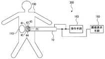
図7に示す構成における本体部10、立体視内視鏡21、並びに処置具41〜45を一括してまたは選択的に操作することができる操作手段160を設けてもよい(図10)。さらに、立体視内視鏡21の観察光学系21b、21c、並びに処置具41〜45の観察光学系41c、42c、43c、44c、45cからの画像を一括して、または、選択的に表示可能な画像表示装置190を設けてもよい。このように構成することによって、省スペース化可能でコンパクトなシステムとなり、より少ない人数の術者によって効率的に治療を行うことができる。  An operation means 160 that can collectively or selectively operate themain body 10, thestereoscopic endoscope 21, and thetreatment tools 41 to 45 in the configuration shown in FIG. 7 may be provided (FIG. 10). Furthermore, images from the observationoptical systems 21b and 21c of thestereoscopic endoscope 21 and the observationoptical systems 41c, 42c, 43c, 44c and 45c of thetreatment tools 41 to 45 can be displayed collectively or selectively. A simpleimage display device 190 may be provided. With this configuration, a space-saving and compact system can be obtained, and treatment can be performed efficiently by a smaller number of surgeons.

本発明について上記実施形態を参照しつつ説明したが、本発明は上記実施形態に限定されるものではなく、改良の目的または本発明の思想の範囲内において改良または変更が可能である。  Although the present invention has been described with reference to the above embodiment, the present invention is not limited to the above embodiment, and can be improved or changed within the scope of the purpose of the improvement or the idea of the present invention.

本発明の実施形態に係る対象物内部処置装置の本体部の構成を示す正面図である。It is a front view which shows the structure of the main-body part of the target object internal treatment apparatus which concerns on embodiment of this invention.図1の線II−IIに沿ってみたときの断面図である。It is sectional drawing when it sees along line II-II of FIG.処置具及び内視鏡が挿入された対象物内部処置装置の構成を示す斜視図である。It is a perspective view which shows the structure of the target object inside treatment apparatus in which the treatment tool and the endoscope were inserted.本発明の実施形態に係る内視鏡の視野範囲における治療の状態の例を示す図である。It is a figure which shows the example of the state of the treatment in the visual field range of the endoscope which concerns on embodiment of this invention.本発明の実施形態に係る対象物内部処置装置の本体部の構成を示す図であって、孔部が5つ設けられている場合の正面図である。It is a figure which shows the structure of the main-body part of the target object internal treatment apparatus which concerns on embodiment of this invention, Comprising: It is a front view in case five holes are provided.図5の線VI−VIに沿ってみたときの断面図である。FIG. 6 is a sectional view taken along line VI-VI in FIG. 5.図5の対象物内部処置装置において処置具及び内視鏡が挿入された状態の構成を示す斜視図である。It is a perspective view which shows the structure of the state in which the treatment tool and the endoscope were inserted in the target object internal treatment apparatus of FIG.本発明の実施形態に係る本体部、内視鏡、処置具と、本体部操作手段、内視鏡操作手段、処置具操作手段、画像表示手段との関係を示すブロック図である。It is a block diagram which shows the relationship between the main-body part, endoscope, treatment tool, main-body part operation means, endoscope operation means, treatment tool operation means, and image display means concerning embodiment of this invention.本発明の実施形態の変形例の構成を示す斜視図である。It is a perspective view which shows the structure of the modification of embodiment of this invention.本発明の実施形態の別の変形例における本体部、内視鏡、処置具と、操作手段、画像表示手段との関係を示すブロック図である。It is a block diagram which shows the relationship between the main-body part, endoscope, treatment tool, an operation means, and an image display means in another modification of embodiment of this invention.

符号の説明Explanation of symbols

10 本体部
11 先端部
11b 先端面(底面)
12 湾曲部
12b 側面
20 中央孔部
21 立体視内視鏡(内視鏡)
30 周辺孔部
31 孔部
32 孔部
33 孔部
34 孔部
35 孔部
41 処置具
42 処置具
43 処置具
44 処置具
45 処置具
60 本体部操作手段
70 内視鏡操作手段
81 処置具操作手段
82 処置具操作手段
100 患者(対象物)体内
110 病変部(対象部位)
200 対象物内部処置装置
300 対象物内部処置システム

10Body 11Tip 11b Tip (bottom)
12 bendingportion12b side surface 20central hole portion 21 stereoscopic endoscope (endoscope)
30peripheral hole part 31hole part 32hole part 33hole part 34hole part 35hole part 41treatment tool 42treatment tool 43treatment tool 44treatment tool 45treatment tool 60 body part operation means 70 endoscope operation means 81 treatment tool operation means 82 Treatment tool operation means 100 Patient (target)body 110 Lesions (target site)
200 ObjectInternal Treatment Device 300 Object Internal Treatment System

Claims (16)

Translated fromJapanese
対象物内部に導入される可撓性を有する円筒状の本体部が、
前記本体部の底面のうち前記対象物側に配置される底面の中央から前記本体部を貫通するように設けられ、対象部位を観察する内視鏡を挿入する中央孔部と、
前記本体部の側面から前記本体部を貫通し、かつその出口側端部の軸線が前記中央孔部に対して前記対象物側に向かうにつれて該中央孔部から離れる方向に傾斜するように設けられ、前記対象部位を処置する処置具を挿入する複数の周辺孔部と、
を備えることを特徴とする対象物内部処置装置。
A flexible cylindrical main body introduced into the inside of the object,
A central hole portion through which the endoscope for observing the target portion is provided so as to penetrate the main body portion from the center of the bottom surface disposed on the object side among the bottom surfaces of the main body portion;
It is provided so asto incline in the direction away from the central hole as it passes through the main body from the side surface of the main bodyand the axis of the outlet side end is directed to the object side with respect to the central hole. A plurality of peripheral holes for inserting a treatment tool for treating the target site;
An object internal treatment device comprising:
対象物内部に導入される可撓性を有する円筒状の本体部であって、
前記本体部の底面のうち前記対象物側に配置される底面の中央から前記本体部を貫通するように設けられ、対象部位を観察する内視鏡を挿入する円形断面の中央孔部、および前記本体部の側面から前記本体部を貫通し、かつその出口側端部の軸線が前記中央孔部に対して前記対象物側に向かうにつれて該中央孔部から離れる方向に傾斜するように設けられ、前記対象部位を処置する処置具を挿入する複数の周辺孔部、を備える本体部と、
前記対象物の外部において前記本体部を操作する本体部操作手段と、
前記対象物の外部において前記内視鏡を操作する内視鏡操作手段と、
前記対象物の外部において前記処置具を操作する処置具操作手段と、
を備えることを特徴とする対象物内部処置システム。
A cylindrical main body having flexibility to be introduced into an object,
A central hole portion with a circular cross section that is provided so as to penetrate the main body portion from the center of the bottom surface disposed on the object side among the bottom surfaces of the main body portion, and inserts an endoscope for observing the target site; and Penetrating through the main body from the side surface of the main body, and provided so asto beinclined in a direction away from the central hole as the axis of the outlet side end moves toward the object side with respect to the central hole . A main body comprising a plurality of peripheral holes into which a treatment tool for treating the target site is inserted; and
A body portion operating means for operating the body portion outside the object;
Endoscope operating means for operating the endoscope outside the object;
A treatment instrument operating means for operating the treatment instrument outside the object;
An object internal treatment system comprising:
前記内視鏡は、対象部位を立体的に観察することができる立体視内視鏡である請求項1記載の対象物内部処置装置。The object internal treatment apparatus according to claim 1, wherein the endoscope is a stereoscopic endoscope capable of observing a target portion in three dimensions.前記処置具は、前記処置具の先端付近を観察可能な観察手段を有する請求項1記載の対象物内部処置装置。The target object internal treatment device according to claim 1, wherein the treatment tool includes an observation unit capable of observing the vicinity of the distal end of the treatment tool.前記処置具は、前記処置具の先端付近を照明可能な照明手段を有する請求項4記載の対象物内部処置装置。The object treatment apparatus according to claim 4, wherein the treatment tool includes an illumination unit that can illuminate the vicinity of the distal end of the treatment tool.前記処置具は、前記観察手段の先端を洗浄可能な送気送水手段を有する請求項5記載の対象物内部処置装置。The object treatment apparatus according to claim 5, wherein the treatment tool includes an air / water supply unit capable of cleaning a tip of the observation unit.前記内視鏡による画像を表示するための画像表示手段を備える請求項2記載の対象物内部処置システム。The object internal treatment system according to claim 2, further comprising image display means for displaying an image obtained by the endoscope.前記内視鏡は、対象部位を立体的に観察することができる立体視内視鏡である請求項2記載の対象物内部処置システム。The object internal treatment system according to claim 2, wherein the endoscope is a stereoscopic endoscope capable of observing a target portion in three dimensions.前記処置具は、前記処置具の先端付近を観察可能な観察手段を有する請求項2記載の対象物内部処置システム。The object treatment system according to claim 2, wherein the treatment tool includes observation means capable of observing the vicinity of the distal end of the treatment tool.前記処置具は、前記処置具の先端付近を照明可能な照明手段を有する請求項9記載の対象物内部処置システム。The target object internal treatment system according to claim 9, wherein the treatment tool includes an illumination unit capable of illuminating the vicinity of the distal end of the treatment tool.前記処置具は、前記観察手段の先端を洗浄可能な送気送水手段を有する請求項10記載の対象物内部処置システム。The object treatment system according to claim 10, wherein the treatment tool includes an air / water supply unit capable of cleaning a tip of the observation unit.前記観察手段による画像を表示するための画像表示手段を備える請求項9記載の対象物内部処置システム。The object internal treatment system according to claim 9, further comprising image display means for displaying an image by the observation means.前記本体部は湾曲自在な湾曲部を有する請求項1記載の対象物内部処置装置。The target body internal treatment device according to claim 1, wherein the main body has a bendable bending portion.前記本体部は湾曲自在な湾曲部を有する請求項2記載の対象物内部処置システム。The object internal treatment system according to claim 2, wherein the main body has a bendable bending portion.前記処置具は湾曲自在な湾曲部を有する請求項1記載の対象物内部処置装置。The target object internal treatment device according to claim 1, wherein the treatment tool has a bendable bending portion.前記処置具は湾曲自在な湾曲部を有する請求項2記載の対象物内部処置システム。

The target object internal treatment system according to claim 2, wherein the treatment instrument has a bendable bending portion.

JP2004011954A2003-07-292004-01-20 Object internal treatment device and object internal treatment systemExpired - LifetimeJP4446045B2 (en)

Priority Applications (4)

Application NumberPriority DateFiling DateTitle
JP2004011954AJP4446045B2 (en)2004-01-202004-01-20 Object internal treatment device and object internal treatment system
DE112004001398TDE112004001398T5 (en)2003-07-292004-07-16 Apparatus for the internal treatment of a patient and system for the internal treatment of a patient
PCT/JP2004/010539WO2005009227A1 (en)2003-07-292004-07-16Internal treatment apparatus for a patient and an internal treatment system for a patient
US10/566,204US8753262B2 (en)2003-07-292004-07-16Internal treatment apparatus having circumferential side holes

Applications Claiming Priority (1)

Application NumberPriority DateFiling DateTitle
JP2004011954AJP4446045B2 (en)2004-01-202004-01-20 Object internal treatment device and object internal treatment system

Publications (2)

Publication NumberPublication Date
JP2005204728A JP2005204728A (en)2005-08-04
JP4446045B2true JP4446045B2 (en)2010-04-07

Family

ID=34898484

Family Applications (1)

Application NumberTitlePriority DateFiling Date
JP2004011954AExpired - LifetimeJP4446045B2 (en)2003-07-292004-01-20 Object internal treatment device and object internal treatment system

Country Status (1)

CountryLink
JP (1)JP4446045B2 (en)

Families Citing this family (12)

* Cited by examiner, † Cited by third party
Publication numberPriority datePublication dateAssigneeTitle
JP2008536552A (en)*2005-04-112008-09-11ユーエスジーアイ メディカル インク. Method and apparatus for off-axis visualization
US9456877B2 (en)*2006-12-012016-10-04Boston Scientific Scimed, Inc.Direct drive instruments and methods of use
EP2224841A4 (en)*2007-11-272012-04-18Univ Washington ADDING IMAGING CAPACITY TO DISTAL ENDS OF MEDICAL, CATHETER, AND CONDUIT TOOLS
US8777839B2 (en)2008-09-022014-07-15Olympus Medical Systems Corp.Shock absorbing mechanism and medical instrument
US8460276B2 (en)*2008-09-022013-06-11Olympus Medical Systems Corp.Manipulation mechanism and medical device instrument
DE102009041510A1 (en)*2009-09-142011-03-31Richard Wolf Gmbh Endoscopic instrument
JP5647780B2 (en)*2009-10-202015-01-07Hoya株式会社 Treatment overtube and treatment system
JP5631177B2 (en)*2009-11-282014-11-26欣也 藤田 Endoscope tubular member
JP6009737B2 (en)2011-04-262016-10-19オリンパス株式会社 Guide sheath and guide sheath system
JP2012245056A (en)*2011-05-252012-12-13Canon IncEndoscope
JP6130993B2 (en)*2012-01-102017-05-17Hoya株式会社 Endoscope for large intestine and endoscope system for large intestine
JP2015526172A (en)*2012-08-092015-09-10メドロボティクス コーポレイション Surgical tool positioning system

Also Published As

Publication numberPublication date
JP2005204728A (en)2005-08-04

Similar Documents

PublicationPublication DateTitle
US8753262B2 (en)Internal treatment apparatus having circumferential side holes
US10869658B2 (en)Devices for introducing multiple instruments and methods of use
JP4446045B2 (en) Object internal treatment device and object internal treatment system
US20110245602A1 (en)Flexible endoscope with full-length lumen
US20120053419A1 (en)Highly Articulable Catheter
JP2001514915A (en) Minimally invasive surgical equipment
WO2008073243A1 (en)Laparoscopic cannula with camera and lighting
JP2007503277A (en) System, apparatus and method for observing hard-to-see parts of a cavity
US11963659B2 (en)Endoscope including an elongate viewing instrument with a pre-biased distal portion
JP6579601B2 (en) Endoscope
KR20160090462A (en)Endoscopic instrument comprising connectors and a cap connected thereto
JP2005046361A (en) Object internal treatment device and object internal treatment system
JP4592007B2 (en) Object internal treatment device and object internal treatment system
US20210068637A1 (en)Endoscope and channel tube
AU2021284265A1 (en)Systems and methods for robotic endoscopic submucosal dissection
JP4479913B2 (en) Object internal treatment device and object internal treatment system
AU2013231368B2 (en)Instrument system for minimally invasive surgery in single port technology
JP2018175868A (en)Endoscopic probe
JP4229511B2 (en) Rigid endoscope
JP7597629B2 (en) Endoscopy
JP7689851B2 (en) Endoscopy
EP3522769B1 (en)An endomicroscopic device
JP7650696B2 (en) Endoscopy
JP2004194827A (en)Endoscope apparatus
KR20110045134A (en) Surgical Instruments

Legal Events

DateCodeTitleDescription
A621Written request for application examination

Free format text:JAPANESE INTERMEDIATE CODE: A621

Effective date:20061211

RD04Notification of resignation of power of attorney

Free format text:JAPANESE INTERMEDIATE CODE: A7424

Effective date:20070621

A711Notification of change in applicant

Free format text:JAPANESE INTERMEDIATE CODE: A712

Effective date:20080501

A131Notification of reasons for refusal

Free format text:JAPANESE INTERMEDIATE CODE: A131

Effective date:20090825

A521Request for written amendment filed

Free format text:JAPANESE INTERMEDIATE CODE: A523

Effective date:20091021

TRDDDecision of grant or rejection written
A521Request for written amendment filed

Free format text:JAPANESE INTERMEDIATE CODE: A821

Effective date:20091021

A01Written decision to grant a patent or to grant a registration (utility model)

Free format text:JAPANESE INTERMEDIATE CODE: A01

Effective date:20091117

A01Written decision to grant a patent or to grant a registration (utility model)

Free format text:JAPANESE INTERMEDIATE CODE: A01

A61First payment of annual fees (during grant procedure)

Free format text:JAPANESE INTERMEDIATE CODE: A61

Effective date:20091208

FPAYRenewal fee payment (event date is renewal date of database)

Free format text:PAYMENT UNTIL: 20130129

Year of fee payment:3

R150Certificate of patent or registration of utility model

Ref document number:4446045

Country of ref document:JP

Free format text:JAPANESE INTERMEDIATE CODE: R150

Free format text:JAPANESE INTERMEDIATE CODE: R150

FPAYRenewal fee payment (event date is renewal date of database)

Free format text:PAYMENT UNTIL: 20130129

Year of fee payment:3

S111Request for change of ownership or part of ownership

Free format text:JAPANESE INTERMEDIATE CODE: R313115

FPAYRenewal fee payment (event date is renewal date of database)

Free format text:PAYMENT UNTIL: 20130129

Year of fee payment:3

R350Written notification of registration of transfer

Free format text:JAPANESE INTERMEDIATE CODE: R350

FPAYRenewal fee payment (event date is renewal date of database)

Free format text:PAYMENT UNTIL: 20130129

Year of fee payment:3

FPAYRenewal fee payment (event date is renewal date of database)

Free format text:PAYMENT UNTIL: 20140129

Year of fee payment:4

R250Receipt of annual fees

Free format text:JAPANESE INTERMEDIATE CODE: R250

S531Written request for registration of change of domicile

Free format text:JAPANESE INTERMEDIATE CODE: R313531

R350Written notification of registration of transfer

Free format text:JAPANESE INTERMEDIATE CODE: R350

R250Receipt of annual fees

Free format text:JAPANESE INTERMEDIATE CODE: R250

R250Receipt of annual fees

Free format text:JAPANESE INTERMEDIATE CODE: R250

R250Receipt of annual fees

Free format text:JAPANESE INTERMEDIATE CODE: R250

R250Receipt of annual fees

Free format text:JAPANESE INTERMEDIATE CODE: R250

R250Receipt of annual fees

Free format text:JAPANESE INTERMEDIATE CODE: R250

R250Receipt of annual fees

Free format text:JAPANESE INTERMEDIATE CODE: R250

R250Receipt of annual fees

Free format text:JAPANESE INTERMEDIATE CODE: R250

EXPYCancellation because of completion of term

[8]ページ先頭

©2009-2025 Movatter.jp