JP4445827B2 - Condensing sheet, surface light source device, and manufacturing method of condensing sheet - Google Patents
Condensing sheet, surface light source device, and manufacturing method of condensing sheetDownload PDFInfo
- Publication number
- JP4445827B2 JP4445827B2JP2004294981AJP2004294981AJP4445827B2JP 4445827 B2JP4445827 B2JP 4445827B2JP 2004294981 AJP2004294981 AJP 2004294981AJP 2004294981 AJP2004294981 AJP 2004294981AJP 4445827 B2JP4445827 B2JP 4445827B2
- Authority
- JP
- Japan
- Prior art keywords
- light
- sheet
- incident
- trapezoid
- condensing
- Prior art date
- Legal status (The legal status is an assumption and is not a legal conclusion. Google has not performed a legal analysis and makes no representation as to the accuracy of the status listed.)
- Expired - Fee Related
Links
Images


Landscapes
- Planar Illumination Modules (AREA)
- Liquid Crystal (AREA)
- Non-Portable Lighting Devices Or Systems Thereof (AREA)
Description
Translated fromJapanese本発明は、液晶表示装置のバックライト装置等に使用される集光シート、面光源装置、集光シートに関するものである。 The present invention relates to a light collecting sheet, a surface light source device, and a light collecting sheet used in a backlight device of a liquid crystal display device.
透過型の液晶ディスプレイ等を背面から照明する面光源として各種方式のバックライトが提案、実用化している。バックライトには、主として、面光源でない光源を面光源に変換する方式によりエッジライト型と直下型とがある。これらいずれの形態のバックライトにおいても、光を適度に集光する集光シートが用いられている(特許文献1参照)。 Various types of backlights have been proposed and put into practical use as surface light sources for illuminating a transmissive liquid crystal display or the like from the back. As the backlight, there are mainly an edge light type and a direct type by converting a light source that is not a surface light source into a surface light source. In any of these types of backlights, a condensing sheet that appropriately condenses light is used (see Patent Document 1).
しかし、上述の従来の集光シートでは、光源からさまざまな角度で入射する光を、目標とする出射角度内に集めきれずに、不要な方向へ出射する光が多く、十分な集光効果を得ることができなかった。
また、正面方向から外れた方向へ出射する光の強度を低く抑え、光の利用効率を高くする面光源素子(レンズシート)が、特許文献2に提案されている。However, in the above-described conventional condensing sheet, light incident at various angles from the light source cannot be collected within the target emission angle, and there is a lot of light emitted in unnecessary directions, so that a sufficient condensing effect is obtained. Couldn't get.
Further,
しかし、特許文献2の図7(a),(b)に記載されているレンズシートでは、反射膜15が錘状凸部11の斜辺部分に設けられているので、平面部12に入射した光が錘状凸部11の内側から斜辺部分に到達しても、反射膜15が形成されておらず空気の場合と比べて、全反射となりにくく、反射時に光量が減少してしまうという問題があった。
また、特許文献2の図7(a),(b)に記載されているレンズシートでは、平面部12に入射せずに斜辺部分に到達した光は、対向している斜辺間で多数回反射を繰返した後に光源側へ戻るので、反射による光量損失が大きいという問題があった。However, in the lens sheet described in FIGS. 7A and 7B of
Further, in the lens sheet described in FIGS. 7A and 7B of
一方、特許文献2の図7(c)には、錘状凸部11の斜辺部分の周りに反射膜15を形成せずに、反射膜15が平面部12と同一面となるように形成した例が図示されている。
特許文献2では、錘状凸部11の斜辺部分の周りと反射膜15とに囲まれた部分が空気であるのか、他の材料で満たされているのかについて、全く示されていない。仮に、錘状凸部11の斜辺部分の周りと反射膜15とに囲まれた部分が、仮に空気であるとすると、反射膜15を形成することが困難であるとともに、反射膜15の固定保持する面積が僅かであり、反射膜15が安定して配置されないという問題が生じてしまう。逆に、錘状凸部11の斜辺部分の周りと反射膜15とに囲まれた部分に他の材料が設けられているとすると、特許文献2の図7(a),(b)に記載されているレンズシートと同様に、全反射となりにくく、反射時に光量が減少してしまうという問題が生じてしまう。
In
本発明の課題は、光源から入射する光を集光することができ、製造が容易で安定して確実に製造することができる集光シート、面光源装置、集光シートの製造方法を提供することである。 An object of the present invention is to provide a condensing sheet, a surface light source device, and a condensing sheet manufacturing method that can collect light incident from a light source and can be manufactured easily, stably, and reliably. That is.
本発明は、以下のような解決手段により、前記課題を解決する。なお、理解を容易にするために、本発明の実施例に対応する符号を付して説明するが、これに限定されるものではない。
請求項1の発明は、シート面に直交する方向の断面形状が略台形形状である単位形状を有し、前記台形の上底部分を入射面(32a)とし、前記台形の下底部分を出射面として前記単位形状をシート面方向に複数並べて配置され光透過性を有し、前記入射面に入射して前記台形の斜辺部(32b)に当たる光を反射して前記出射面に向けることにより出射光を集光する導光部(32)と、前記導光部の単位形状の間に設けられた空隙部(S)と、前記入射面上に接合するとともに、前記空隙部を覆うように配置されたフィルムであって、前記入射面に対応する位置にあって光を透過する透過部(33a)と、前記空隙部に入射しようとする光を反射する反射部(34)とを有した入射光選別フィルム部(33,34)と、を備える集光シート(30)であって、前記入射光選別フィルム部は、前記透過部を含む光を透過する透明層(33)と、前記透明層の入射側に別層として前記空隙部を覆う位置に設けられ、光を反射する前記反射部を形成する反射層(34)と、を備え、シートの法線と前記単位形状の前記斜辺部との成す角度をα、前記単位形状の台形の下底部分の幅をP、前記透明層の厚さをTとすると、前記台形の高さに相当する前記単位形状の下底部分から上底部分までの距離Hは、H=(P−T×tan2α)/(tanα+tan2α)の関係を略満足すること、を特徴とする集光シート(30)である。
請求項2の発明は、請求項1に記載の集光シートにおいて、最大出射角度をω、シートの法線と前記単位形状の前記斜辺部(32b)との成す角度をα、前記導光部(32)の屈折率をNとしたとき、前記単位形状は、(sin-1(1/N)−sin-1(sinω/N))/2<α<(sin-1(sinω/N))/2の関係を略満足すること、を特徴とする集光シート(30)である。The present invention solves the above problems by the following means. In order to facilitate understanding, description will be made with reference numerals corresponding to the embodiments of the present invention, but the present invention is not limited to this.
The invention of
According to a second aspect of the present invention, in the condensing sheet according to the first aspect, the maximum emission angle is ω, the angle between the normal line of the sheet and the oblique side portion (32b) of the unit shape is α, and the light guide portion When the refractive index of (32) is N, the unit shape is (sin−1(1 / N) −sin−1(sinω / N)) / 2 <α <(sin−1(sinω / N). ) / 2 is substantially satisfied, the light collecting sheet (30).
請求項3の発明は、シート面に直交する方向の断面形状が略台形形状である単位形状を有し、前記台形の上底部分を入射面(32a)とし、前記台形の下底部分を出射面として前記単位形状をシート面方向に複数並べて配置され光透過性を有し、前記入射面に入射して前記台形の斜辺部(32b)に当たる光を反射して前記出射面に向けることにより出射光を集光する導光部(32)と、前記導光部の単位形状の間に設けられた空隙部(S)と、前記入射面上に接合するとともに、前記空隙部を覆うように配置されたフィルムであって、前記入射面に対応する位置にあって光を透過する透過部(33a,233a)と、前記空隙部に入射しようとする光を反射する反射部(34,233b)とを有した入射光選別フィルム部(33,34,233)と、を備える集光シートであって、最大出射角度をω、シートの法線と前記単位形状の前記斜辺部との成す角度をα、前記導光部の屈折率をNとしたとき、前記単位形状は、(sinThe invention of
請求項4の発明は、請求項3に記載の集光シートにおいて、前記透過部(233a)及び前記反射部(233b)は、前記入射光選別フィルム部の厚さ方向において同一層となる位置に形成されていること、を特徴とする集光シート(230)である。According to a fourth aspect of the present invention, there is provided the light collecting sheet according to thethird aspect , wherein the transmission part (233a) and the reflection part (233b) are in the same layer in the thickness direction of the incident light selection film part. The light collecting sheet (230) is characterized by being formed.
請求項5の発明は、請求項1から請求項4までのいずれか1項に記載の集光シートにおいて、前記導光部(32)の前記入射面(32a)に対応する前記透過部(33a,233a)の表面は、平坦面であること、を特徴とする集光シート(30,230)である。
請求項6の発明は、請求項1から請求項5までのいずれか1項に記載の集光シートにおいて、前記入射光選別フィルム部(33,34,233)は、前記単位形状とは別に形成されたフィルムを用いて形成されていること、を特徴とする集光シート(30,230)である。
請求項7の発明は、請求項1から請求項6までのいずれか1項に記載の集光シートにおいて、前記単位形状は、断面形状が略台形の四角錘台又は円錐台であること、を特徴とする集光シートである。
請求項8の発明は、請求項1から請求項7までのいずれか1項に記載の集光シートにおいて、前記導光部(32)は、略台形の断面形状が一方向に延在する前記単位形状を平行に多数並べて形成されていること、を特徴とする集光シート(30,230)である。Invention請 Motomeko5, the condensing sheet according to any one of
According to asixth aspect of the present invention, in the light collecting sheet according to any one of the first tofifth aspects, the incident light sorting film portion (33, 34, 233) is formed separately from the unit shape. It is formed using the made film, It is a condensing sheet | seat (30,230) characterized by the above-mentioned.
The invention according to claim7 is the light collecting sheet according to any one of
The invention of claim8 is the light collecting sheet according to any one of
請求項9の発明は、請求項1から請求項8までのいずれか1項に記載の集光シート(30,230)と、前記集光シートに入射する光を発する光源(10)と、を備える面光源装置である。
請求項10の発明は、請求項8に記載の集光シートをその単位形状の並ぶ方向が直交するように積層配置した複数の集光シートと、前記集光シートに入射する光を発する光源と、を備える面光源装置である。
請求項11の発明は、集光シート(30,230)と、前記集光シートに入射する光を発する光源と、を備える面光源装置であって、前記集光シートは、シート面に直交する方向の断面形状が略台形形状である単位形状を有し、前記台形の上底部分を入射面(32a)とし、前記台形の下底部分を出射面として前記単位形状をシート面方向に複数並べて配置され光透過性を有し、前記入射面に入射して前記台形の斜辺部(32b)に当たる光を反射して前記出射面に向けることにより出射光を集光する導光部(32)と、前記導光部の単位形状の間に設けられた空隙部(S)と、前記入射面上に接合するとともに、前記空隙部を覆うように配置されたフィルムであって、前記入射面に対応する位置にあって光を透過する透過部(33a,233a)と、前記空隙部に入射しようとする光を反射する反射部(34,233b)とを有した入射光選別フィルム部(33,34,233)とを備え、前記導光部は、略台形の断面形状が一方向に延在する前記単位形状を平行に多数並べて形成され、前記集光シートは、その単位形状の並ぶ方向が直交するように複数積層配置されていること、を特徴とする面光源装置である。
請求項12の発明は、請求項9から請求項11までのいずれか1項に記載の面光源装置において、前記集光シート(30,230)と前記光源(10)との間に、拡散シート(20)を配置したこと、を特徴とする面光源装置である。
請求項13の発明は、請求項12に記載の面光源装置において、前記集光シート(30,230)の少なくとも一部は、紫外線硬化及び/又は光反応性樹脂を用いて形成されており、前記拡散シートは(20)、紫外線吸収作用を有すること、を特徴とする面光源装置である。The invention of claim9 includes the light collecting sheet (30, 230) according to any one of
Atenth aspect of the present invention is a plurality of condensing sheets in which the condensing sheets according to theeighth aspect are stacked so that the direction in which the unit shapes are arranged orthogonal to each other; a light source that emits light incident on the condensing sheets; Are surface light source devices.
The invention of claim 11 is a surface light source device comprising a light collecting sheet (30, 230) and a light source that emits light incident on the light collecting sheet, wherein the light collecting sheet is orthogonal to the sheet surface. A unit shape having a substantially trapezoidal cross-sectional shape, and a plurality of the unit shapes are arranged in the sheet surface direction with the upper base portion of the trapezoid as an incident surface (32a) and the lower base portion of the trapezoid as an output surface. A light guide part (32) that is arranged and has light transparency, and that collects outgoing light by reflecting light incident on the incident surface and impinging on the trapezoidal hypotenuse (32b) and directing it to the outgoing surface; And a gap (S) provided between the unit shapes of the light guide part, and a film that is joined to the incident surface and is disposed so as to cover the gap part, and corresponds to the incident surface Transmitting portions (33a, 23) that transmit light through a) and an incident light selection film part (33, 34, 233) having a reflection part (34, 233b) that reflects light that is about to enter the gap part, and the light guide part is substantially The trapezoidal cross-sectional shape is formed by arranging a large number of the unit shapes extending in one direction in parallel, and the light collecting sheets are arranged in a plurality of layers so that the direction in which the unit shapes are arranged is orthogonal. The surface light source device.
A twelfth aspect of the present invention is the surface light source device according toany one of theninth to eleventh aspects, wherein the diffusion sheet is disposed between the condensing sheet (30, 230) and the light source (10). The surface light source device is characterized in that (20) is arranged.
The invention of claim 13 is the surface light source device according to claim 12, wherein at least a part of the condensing sheet (30, 230) is formed using ultraviolet curing and / or photoreactive resin, The diffusion sheet (20) is a surface light source device characterized by having an ultraviolet absorbing function.
請求項14の発明は、請求項1から請求項8までのいずれか1項に記載の集光シート(30,230)の製造方法であって、前記入射光選別フィルム部(33,34,233)の前記透過部(33a,233a)及び/又は反射部(34,233b)は、前記台形の斜辺部(32b)により反射することができるエネルギー線を前記単位形状の前記台形の下底部分からシートの略法線方向から照射することにより形成すること、を特徴とする集光シートの製造方法である。
請求項15の発明は、シート面に直交する方向の断面形状が略台形形状である単位形状を有し、前記台形の上底部分を入射面(32a)とし、前記台形の下底部分を出射面として前記単位形状をシート面方向に複数並べて配置され光透過性を有し、前記入射面に入射して前記台形の斜辺部(32b)に当たる光を反射して前記出射面に向けることにより出射光を集光する導光部(32)と、前記導光部の単位形状の間に設けられた空隙部(S)と、前記入射面上に接合するとともに、前記空隙部を覆うように配置されたフィルムであって、前記入射面に対応する位置にあって光を透過する透過部(33a,233a)と、前記空隙部に入射しようとする光を反射する反射部(34,233b)とを有した入射光選別フィルム部(33,34,233)と、を備える集光シート(30,230)の製造方法であって、前記入射光選別フィルム部の前記透過部及び/又は反射部は、前記台形の斜辺部により反射することができるエネルギー線を前記単位形状の前記台形の下底部分からシートの略法線方向から照射することにより形成すること、を特徴とする集光シートの製造方法である。A fourteenth aspect of the present invention is the method of manufacturing the light collecting sheet (30, 230) according to any one of the first toeighth aspects, wherein the incident light sorting film portion (33, 34, 233) is provided. The transmission part (33a, 233a) and / or the reflection part (34, 233b) of the above-mentioned unit transmits an energy ray that can be reflected by the trapezoidal hypotenuse (32b) from the lower base part of the trapezoid of the unit shape. It forms by irradiating from the substantially normal line direction of this. It is a manufacturing method of the condensing sheet characterized by the above-mentioned.
The invention of claim 15 has a unit shape in which the cross-sectional shape in a direction perpendicular to the sheet surface is a substantially trapezoidal shape, the upper base portion of the trapezoid is used as an incident surface (32a), and the lower base portion of the trapezoid is emitted. A plurality of unit shapes arranged side by side in the sheet surface direction as a surface have light transmittance, and are emitted by reflecting light incident on the incident surface and impinging on the trapezoid hypotenuse (32b) and directing it to the exit surface. A light guide part (32) for condensing incident light, a gap part (S) provided between unit shapes of the light guide part, and arranged so as to be joined to the incident surface and to cover the gap part A transmissive portion (33a, 233a) that transmits light at a position corresponding to the incident surface, and a reflective portion (34, 233b) that reflects light entering the gap portion. Incident light sorting film part (33, 34, 33), wherein the transmitting part and / or the reflecting part of the incident light sorting film part can be reflected by the trapezoidal hypotenuse part. It is formed by irradiating a line from the lower base part of the trapezoid of the unit shape from a substantially normal direction of the sheet.
本発明によれば、以下の効果を奏することができる。
(1)入射面上に接合するとともに、空隙部を覆うように配置されたフィルムであって、入射面に対応する位置にあって光を透過する透過部と、空隙部に入射しようとする光を反射する反射部とを有した入射光選別フィルム部を備えるので、反射部を容易に形成することができ、形成された反射部を安定して保持することができる。また、空隙部を有していることから、全反射を利用して光を効率よく集光することができる。According to the present invention, the following effects can be obtained.
(1) A film that is bonded on the incident surface and is disposed so as to cover the gap, and is a transmission portion that transmits light at a position corresponding to the incidence surface, and light that is about to enter the gap. Since the incident light selection film part having the reflection part for reflecting the light is provided, the reflection part can be easily formed, and the formed reflection part can be stably held. Moreover, since it has a space | gap part, light can be efficiently condensed using total reflection.
(2)入射光選別フィルム部は、透過部を含む光を透過する透明層と、透明層の入射側に別層として空隙部を覆う位置に設けられ、光を反射する反射部を形成する反射層とを備えるので、反射層の形成に利用できる手法が多く、集光シートの製造を容易に行うことができる。また、光源側に設けられている他の光学要素と接触したときのニュートンリングの発生を防ぐことができる。(2) The incident light sorting film part is provided at a position where the transparent part including the transmissive part transmits light and at a position covering the gap as a separate layer on the incident side of the transparent layer, and forms a reflective part that reflects the light. Since the method includes a layer, there are many methods that can be used for forming the reflective layer, and the light collecting sheet can be easily manufactured. In addition, Newton's ring can be prevented from occurring when it comes into contact with another optical element provided on the light source side.
(3)台形の高さに相当する単位形状の下底部分から上底部分までの距離Hは、H=(P−T×tan2α)/(tanα+tan2α)の関係を略満足するので、反射層の製造に適した台形形状であって、集光特性も良好にすることができる。(3) The distance H from the lower base portion to the upper base portion of the unit shape corresponding to the height of the trapezoid substantially satisfies the relationship of H = (P−T × tan 2α) / (tan α + tan 2α). The trapezoidal shape is suitable for the above, and the light collecting property can be improved.
(4)透過部及び反射部は、入射光選別フィルム部の厚さ方向において同一層となる位置に形成されているので、より簡単に集光シートを製造することができる。また、入射光選別フィルムの透過部に斜めに入射してそのまま通過してしまう光線が反射層のサイド面で反射されるので損失を少なくすることができる。(4) Since the transmission part and the reflection part are formed in the same layer in the thickness direction of the incident light selection film part, the light collecting sheet can be manufactured more easily. In addition, since the light beam that is incident on the transmission portion of the incident light selection film obliquely and passes as it is is reflected by the side surface of the reflection layer, loss can be reduced.
(5)前記単位形状は、(sin-1(1/N)−sin-1(sinω/N))/2<α<(sin-1(sinω/N))/2の関係を略満足するので、効率よく光を集光することができる。(5) The unit shape substantially satisfies the relationship of (sin−1 (1 / N) −sin−1 (sin ω / N)) / 2 <α <(sin−1 (sin ω / N)) / 2. Therefore, light can be collected efficiently.
(6)導光部の入射面に対応する透過部の表面は、平坦面であるので、損失光を生じず、光の利用効率を高くすることができる。(6) Since the surface of the transmission part corresponding to the incident surface of the light guide part is a flat surface, no loss of light is generated and the light use efficiency can be increased.
(7)入射光選別フィルム部は、単位形状とは別に形成されたフィルムを用いて形成されているので、集光フィルムの製造を容易にすることができる。(7) Since the incident light selection film portion is formed using a film formed separately from the unit shape, it is possible to facilitate the production of the light collecting film.
(8)単位形状は、断面形状が略台形の四角錘台又は円錐台であるので、一枚の集光シートにより、2方向又は全方向の集光を行うことができる。(8) Since the unit shape is a quadrangular frustum or a truncated cone having a substantially trapezoidal cross-sectional shape, light can be condensed in two directions or in all directions by a single condensing sheet.
(9)導光部は、略台形の断面形状が一方向に延在する単位形状を平行に多数並べて形成されているので、導光部の製造を容易に行うことができる。(9) Since the light guide section is formed by arranging a large number of unit shapes each having a substantially trapezoidal cross-sectional shape extending in one direction, the light guide section can be easily manufactured.
(10)単位形状の並ぶ方向が直交するように積層配置した複数の集光シートを備える面光源装置であるので、直交する2方向の集光を行うことができる。(10) Since the surface light source device includes a plurality of light collecting sheets stacked and arranged so that the direction in which the unit shapes are arranged is orthogonal, it is possible to collect light in two orthogonal directions.
(11)集光シートと光源との間に、拡散シートを配置したので、ムラのない均一な照明を行うことができる。(11) Since the diffusion sheet is disposed between the light collecting sheet and the light source, uniform illumination without unevenness can be performed.
(12)拡散シートは、紫外線吸収作用を有するので、集光シートの少なくとも一部に紫外線硬化及び/又は光反応性樹脂を用いて形成されていても、照明光により黄変するなどの不都合を生じることなく、製品寿命を長くすることができる。(12) Since the diffusion sheet has an ultraviolet absorbing action, even if it is formed using at least a part of the condensing sheet using ultraviolet curing and / or a photoreactive resin, there is a problem such as yellowing by illumination light. The product life can be extended without the occurrence.
(13)入射光選別フィルム部の透過部及び/又は反射部は、台形の斜辺部により反射することができるエネルギー線を単位形状の台形の下底部分からシートの略法線方向から照射することにより形成するので、反射層を精度よく、かつ、簡単に製造することができる。(13) The transmission part and / or the reflection part of the incident light selection film part is irradiated with energy rays that can be reflected by the hypotenuse of the trapezoid from the lower base part of the unit shape trapezoid from the substantially normal direction of the sheet. Since it forms, a reflective layer can be manufactured accurately and easily.
光源からさまざまな角度で入射する光を集光するという目的を、セルフアライメントを利用して製造が容易で安定して確実に製造することができるようにして実現した。 The purpose of collecting light incident at various angles from the light source has been realized by using self-alignment so that it can be manufactured easily, stably and reliably.
図1は、本発明による集光シート30を含む面光源装置の実施例1を示す図である。
本実施例による面光源装置は、光源10,拡散板20,集光シート30,反射板40等を有し、枠部50により保持されている。
光源10は、照明光を発光する部分であり、複数の陰極線管を平行に並べて形成されている。光源の光を出射させる方向と反対側には、反射板40が配置され、反射板40の方向に進んだ光を必要な出射方向へ反射する。FIG. 1 is a diagram showing Example 1 of a surface light source device including a
The surface light source device according to this embodiment includes a
The
拡散板20は、通常の樹脂に拡散剤とベンゾフェノン系、ベンゾトリアゾール系、シアノアクリレート系、サリチレート系等の紫外線吸収剤を練りこんだフィルム、拡散ビーズと紫外線吸収剤をコーティングしたフィルム、レンチキュラー形状を表面に付与した紫外線吸収剤入りのフィルム等の紫外線吸収剤と拡散剤と拡散用レンズ形状の組み合わせを用いることができる。
拡散板20は、光源10からの照明光を拡散し、陰極線管に近いか否かによる照明ムラをなくし、輝度分布が均一な照明光とする役割を果たしている。したがって、拡散板20から出射する照明光は、様々な出射角度で出射する。特に、本実施例の集光シート30は、集光度合いが高いので、拡散板の拡散を大きくすることにより輝度の均一性や拡散板のタワミ防止の支柱の影の防止等のムラ発生要因の軽減が可能となる。
後述する集光シート30は、紫外線硬化樹脂や光反応性樹脂を用いて形成されており、また、光源10は、紫外光も発光するが、拡散板20が紫外線吸収作用を有しているので、この紫外光により集光シート30が黄変等することを防止している。The diffusing
The
The
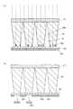
集光シート30は、支持フィルム31,導光部32,透明層33,反射層34を有している。
支持フィルム31は、集光シート30を支持するベースとなるフィルムである。支持フィルム31には、通常の透明フィルムが使用可能だが、耐熱性、低吸湿性等の温度、湿度変化で動きの少ない材料がより好ましい。また、紫外線を使用したセルフアライメントでの製造では紫外線透過率の高い材料、赤外線を用いたセルフアライメントでは赤外線透過率の高い材料が好ましい。The
The
導光部32は、支持フィルム31上に一体となるように形成され、シート面に直交する方向の断面形状が略台形形状で延在する単位形状を有している。導光部32は、その台形の上底部分を入射面32aとし、台形の下底部分を出射面となるようにして単位形状をシート面方向に縞状に並べて配置されている。また、導光部32は、光透過性を有したUV硬化樹脂により形成されている。なお、導光部32には、屈折率1.41以上のウレタンアクリレート、エポキシアクリレート、ポリエステルアクリレート等のUVやEB硬化樹脂やMMAの熱重合(キャスティング)等賦型性の良好な成型法が可能な樹脂を用いるとよい。 The
導光部32は、入射面32aに入射してその台形の斜辺部32bに当たる光を反射して出射面に向けることにより出射光を集光する。なお、導光部32の単位形状の間には、空隙部Sが形成されている。この空隙部Sは、空気が存在しており、斜辺部32bは、光を全反射することができ、斜辺部32bにより反射しても光量が減少せず、効率よく照明光を出射できるようになっている。 The
透明層33は、PET(polyethylene terephthalate),PC(polycarbonate),PMMA(polymethyl methacrylate),オレフィン,St(styrene)等により形成された透明フィルムであり、特に、PETのように薄くとも強度の高い物が望ましく、導光部32の入射面32a上に接合するとともに、空隙部Sを覆うように配置されている。なお、透明層33には、多層フィルムを用いたり、コーティング層を形成したりしてもよい。
反射層34は、空隙部Sに入射しようとする光を反射する反射部であり、アルミニウム、銀等の反射率の高い金属膜により正規反射層として形成されている。透明層33の反射層34が形成されていない部分は、光を透過する透過部33aとなっており、この透過部33aの表面(入射面)は、平坦面となっている。
これら透明層33と反射層34が組み合わせて設けられることにより、入射光選別フィルム部が形成されている。The
The
By providing the
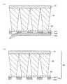
図2及び図3は、集光シート30の製造過程を示す図である。
支持フィルム31上への導光部32の製造は、従来から用いられているUV硬化樹脂とロール金型を用いた成型方法により行う。そして、台形の上底に相当する入射面32a上に、感光性粘着層341を塗布又は転写して形成する。この感光性粘着層341は、屈折率不問でカチオン系、ラジカル系の反応性粘着剤が用いられ、初期状態では粘着性を有し、特定の光が照射されると、照射された部分の粘着性が失われて硬化する性質を有している。2 and 3 are diagrams showing a manufacturing process of the
Manufacture of the
感光性粘着層341を形成した後、支持フィルム31側(台形の下底側)から感光性粘着層341が感度を有する光を照射して感光性粘着層341を露光する(図2(a))。このとき、台形の下底側から入射した光は、導光部32の斜辺部32bにより全反射して、入射面32aのみから出射することとなる。したがって、入射面32aに対応した位置にある感光性粘着層341は、粘着性が失われて硬化して感光済層342となるが、空隙部Sに対応した位置にある感光性粘着層341には、特に変化が生じず、粘着性を保っている。 After forming the photosensitive
露光を行った後に、感光済層342を選択的に除去する(図2(b))。この除去方法は、例えば、不図示の粘着シートを貼り付けて感光済層342のみを除去してもよいし、洗浄して除去してもよい。 After the exposure, the exposed
感光済層342を除去した後、アルミニウムからなる反射材343を基材層344上に蒸着した蒸着転写紙を感光性粘着層341上に接合し、基材層344を剥がす(図3(a))。このとき、感光性粘着層341と接合した部分の反射材343は、感光性粘着層341に接合したまま残り反射層34が形成され、入射面32aに対応した位置にある反射材343は、基材層344と共に除去され、集光シート30が完成する(図3(b))。本実施例では、蒸着転写紙を用いているので、形成された反射層34は、先に述べたように正規反射層となる。 After removing the exposed
このように、本実施例における集光シート30は、導光部32の有している光学的特性を利用して感光性粘着層341への露光を選択的に行う所謂セルフアライメントと呼ばれる手法を用いたので、反射層34を必要な位置に精度よく、しかも簡単に形成することができる。
なお、集光シート30の製造方法は、上述の方法の他に、例えば、感光粘着と転写で反射層を形成すれば除去する必要がなくなり製造コストを下げることができる。
また、通常の感光樹脂を用いて露光後蒸着やスパッタ等で反射層を設けリフトオフしてもよく、その場合には、透過部のみ感光層が除去される。
さらに、露光後反射部の未感光の感光層を除去し透過部は感光層で保護した状態で蒸着やスパッタ等で反射層を設けた後、透過部に残っている感光済みの感光層を除去してもよい。その場合には、感光層は残らないこととなる。As described above, the
In addition to the above-described method, for example, if the reflective layer is formed by photosensitive adhesive and transfer, the
In addition, a reflective layer may be provided by post-exposure vapor deposition or sputtering using a normal photosensitive resin, and lift-off may be performed. In this case, only the transmissive portion is removed from the photosensitive layer.
Furthermore, after exposure, the non-photosensitive photosensitive layer in the reflective portion is removed and the reflective portion is provided by vapor deposition or sputtering while the transmissive portion is protected by the photosensitive layer, and then the exposed photosensitive layer remaining in the transmissive portion is removed. May be. In that case, the photosensitive layer does not remain.
次に、集光シート30の形状を決める上での必要な要件について説明する。
まず、光を集光させる作用から、導光部32の斜辺部32bの角度について説明する。
透明層33の厚さをT、導光部32の台形の高さをHとし、TがHと比べて十分に小さいとき、光源10からの照明光は、台形の上底部分(入射面32a)のみに入射するとみなすことができる。ここで、希望の最大出射角度をω、シートの法線と前記単位形状の前記斜辺部との成す角度(斜面角度)をα、出射面への入射角度をβ、出射角度をγ、上底部分(入射面32a)から入射して、斜面に当たらないで出射する光の出射面への最大入射角度をβ1、最大出射角度γ1、導光部32の屈折率をNとすると、
β1=2×α
γ1=sin-1(N×sinβ1)<ω
よって、
α<(sin-1(sinω/N))/2Next, requirements necessary for determining the shape of the
First, the angle of the
When the thickness of the
β1 = 2 × α
γ1 = sin−1 (N × sin β1 ) <ω
Therefore,
α <(sin−1 (sin ω / N)) / 2
一方、斜面に一回当たって出射する光の出射面への最大入射角度をβ2、最大出射角度γ2とすると、入射面に入射する光の最大角度は90度であるから、
β2=sin-1(1/N)−2×α
γ2=sin-1(N×sinβ2)<ω
よって、
(sin-1(1/N)−sin-1(sinω/N))/2<α
即ち、斜面角度αの範囲は、
(sin-1(1/N)−sin-1(sinω/N))/2<α<(sin-1(sinω/N))/2
を満たすようにするとよい。On the other hand, if the maximum incident angle on the exit surface of the light emitted once hitting the slope is β2 and the maximum exit angle γ2 , the maximum angle of the light incident on the incident surface is 90 degrees.
β2 = sin−1 (1 / N) −2 × α
γ2 = sin−1 (N × sin β2 ) <ω
Therefore,
(Sin−1 (1 / N) −sin−1 (sin ω / N)) / 2 <α
That is, the range of the slope angle α is
(Sin−1 (1 / N) −sin−1 (sin ω / N)) / 2 <α <(sin−1 (sin ω / N)) / 2
It is good to satisfy.
なお、斜辺部32bでの全反射条件は、
N×sin(90−(sin-1(1/N)−α))>1
よって、
α>sin-1(1/N)−cos-1(1/N)
となり、α>0であるから、Nが1.4142以上、即ち、通常の透明樹脂であれば必ず全反射する。
また、β1>β2、即ち、
(sin-1(1/N))/4<α
であるときには、斜辺部32bに当たらない光γ1が最大出射角度γとなり、
β1<β2、即ち、
(sin-1(1/N))/4>α
であるときには、斜辺部32bに当たった光γ2が最大出射角度γとなる。The total reflection condition at the
N × sin (90− (sin−1 (1 / N) −α))> 1
Therefore,
α> sin−1 (1 / N) −cos−1 (1 / N)
Since α> 0, N is 1.4142 or more, that is, if it is a normal transparent resin, it is always totally reflected.
Β1 > β2 , that is,
(Sin−1 (1 / N)) / 4 <α
, The light γ1 that does not strike the
β1 <β2 , ie
(Sin−1 (1 / N)) / 4> α
, The light γ2 impinging on the
図4は、台形の高さHの変化による反射層34の形成される幅の変化を説明する図である。
ここで、反射層34の形成過程における露光時の条件から導光部32の台形の高さHについて説明する。
導光部32の単位形状の下底部の幅をP、下底部と斜辺部32bとの交点と、透過部33aと反射層34との境界部とを結ぶ線を進む光線L1がシートの法線と成す角をψとすると、
ψ=2α、tanα=R/H、tan2α=(P−R)/(H+T)であるから、
H=(P−T×tan2α)/(tanα+tan2α)となる。
Hがこれより高いと、反射層を形成する際の露光時に、光出射面から露光した光が広がり、反射層の幅Rが狭くなってしまう(図4中のR2)。そして、反射層の幅が狭くなった部分からの照明の入射光は、空隙部Sに入射し、損失光となってしまう。FIG. 4 is a diagram for explaining a change in the width in which the
Here, the trapezoidal height H of the
The width of the lower bottom part of the unit shape of the light guide part P is P, and the light ray L1 traveling along the line connecting the intersection of the lower bottom part and the
Since ψ = 2α, tanα = R / H, and tan2α = (PR) / (H + T),
H = (P−T × tan2α) / (tanα + tan2α).
If H is higher than this, at the time of exposure when forming the reflective layer, the exposed light spreads from the light exit surface, and the width R of the reflective layer becomes narrow (R2 in FIG. 4). And the incident light of the illumination from the part where the width | variety of the reflection layer became narrow enters into the space | gap part S, and will be lost light.
次に、面光源装置として使用するときの条件から、導光部32の台形の高さHについて説明する。
図5は、面光源として使用している状態における台形の高さHの変化の影響を示す図である。
面光源装置として使用するときには、入射光を斜辺部32bに当てて反射させることにより出射角度を小さくする(集光する)が、Hが小さい(台形の高さが低い)と、斜辺部32bに当たることなく、そのまま出射してしまう角度ψが大きくなり出射角度の大きい光が増える(集光が不十分となる)。即ち、出射角度を小さくするには、Hを大きくすることが望ましい。
したがって、Hは、(P−T×tan2α)/(tanα+tan2α)近傍の値とするとよい。Next, the trapezoidal height H of the
FIG. 5 is a diagram showing the influence of the change in the height H of the trapezoid in the state where it is used as a surface light source.
When used as a surface light source device, the incident light is applied to the
Therefore, H is preferably a value in the vicinity of (P−T × tan2α) / (tanα + tan2α).
さらに、透明層33の厚さT及びその屈折率nについて説明する。
照明光が図5中のLの範囲に入射して、空隙部Sに進んでしまい、面光源装置の照明光として利用することができない損失光は、少なくする必要がある。図5から明らかなように、このLの範囲を少なくすれば、損失光を少なくすることができる。図5の関係を数式により示すと、以下のようになる。
n×sinξ=sinθ
L=T×tanξ
よって、
L=(T×sinθ)/(n2−sin2θ)1/2
θの最大値は、90度であるから
L=T/(n2−1)1/2
したがって、このLの寸法を少なくするためには、透明層33の厚さTが薄く、透明層33の屈折率nが高いほうがよく、損失光を少なくすることができる。
なお、この式は、P、Hと無関係であり、ピッチを大きくする事で実質的に透明層の厚みを小さくすれば損失の割合を減少できる。Further, the thickness T and the refractive index n of the
It is necessary to reduce the loss of light that enters the range L in FIG. 5 and proceeds to the gap S and cannot be used as the illumination light of the surface light source device. As is apparent from FIG. 5, the loss of light can be reduced by reducing the L range. The relationship of FIG. 5 is expressed as follows:
n × sinξ = sinθ
L = T × tanξ
Therefore,
L = (T × sin θ) / (n2 −sin2 θ)1/2
Since the maximum value of θ is 90 degrees, L = T / (n2 −1)1/2
Therefore, in order to reduce the dimension of L, it is better that the thickness T of the
Note that this equation is independent of P and H, and the loss ratio can be reduced if the thickness of the transparent layer is substantially reduced by increasing the pitch.
なお、先に示したように、本実施例では、透過部33aの表面(入射面)は、平坦面となっている。入射面が平坦面であると、最大入射角度である90度入射のときの導光部32(透明層33とほぼ同じ屈折率と仮定:異なっても通常の材料の屈折率の範囲ではほぼ同じと考えて問題ない)内の角度ξは、
N×sinξ=sin90=1
また、斜辺部32bへの入射角度は、90+α−ξであり、最も全反射しづらい斜辺部32bの角度αが0度の場合の全反射条件は、
N×sin(90−ξ)>1
である。これらの関係から、N>√2=1.414となる。通常の材料では、屈折率は、1.414以上であることから、通常の材料を用いる限り、入射光角度によらず斜面で全反射することができる。一方、入射面が平坦面でないと、導光部内の角度ξの最大値が限定されないので斜辺部32bでの全反射が起きない入射光成分が生じ、損失光が発生してしまう。よって、本実施例の透過部33aの表面のように、入射面は、平坦面とすることがよい。As described above, in the present embodiment, the surface (incident surface) of the transmission portion 33a is a flat surface. When the incident surface is a flat surface, the light guide section 32 (assuming substantially the same refractive index as that of the transparent layer 33) when the maximum incident angle is 90 degrees is assumed. The angle ξ within is
N × sinξ = sin90 = 1
The incident angle to the
N × sin (90−ξ)> 1
It is. From these relationships, N> √2 = 1.414. A normal material has a refractive index of 1.414 or more, and therefore, as long as a normal material is used, it can be totally reflected on a slope regardless of the incident light angle. On the other hand, if the incident surface is not a flat surface, the maximum value of the angle ξ in the light guide portion is not limited, so that an incident light component that does not cause total reflection at the
(本実施例における反射層の他の形成方法)
本実施例では、反射層34を、感光性粘着層341と蒸着転写紙を用いて形成したが、その他の方法を、以下に例示する。
(1)上記実施例では、感光性粘着層341の粘着性の残った未露光部に、蒸着転写紙を接合して正規反射層を形成したが、蒸着転写紙に代えて、例えば、チタンホワイト、炭酸カルシウム、硫酸バリウム等の白色拡散転写紙を接合すれば拡散反射層を形成することができる。また、感光性粘着層341に白色粉体を直接接合してもよい。
なお、特に拡散反射層とする場合には、反射層表面そのものが拡散反射することが好ましい。
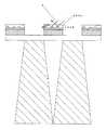
図6は、反射層434の最表面に透明層434aが形成されている例を示す図である。
図6のように、反射層434の最表面に透明層434aが形成されている場合とは、例えば、転写における離型層等が挙げられる。このような層があると、図6のように、拡散反射面の位置によっては透明層434aの表面で全反射する光Aが発生し、反射効率の低下が生じてしまう。したがって、拡散反射層とする場合には、反射層表面そのものが拡散反射することが好ましい。(Other methods of forming the reflective layer in this example)
In this embodiment, the
(1) In the above embodiment, the regular reflection layer was formed by bonding the vapor-deposited transfer paper to the unexposed portion of the photosensitive
In particular, in the case of a diffuse reflection layer, the reflection layer surface itself is preferably diffusely reflected.
FIG. 6 is a diagram illustrating an example in which a transparent layer 434 a is formed on the outermost surface of the
As shown in FIG. 6, the case where the transparent layer 434a is formed on the outermost surface of the
(2)透明層にポジ型感光性樹脂を塗布した後に露光現像し、蒸着等により反射層を設けた後、光透過部上の反射層を感光性樹脂層と共に取り除くことにより反射層を形成してもよい。(2) A positive photosensitive resin is applied to the transparent layer, exposed and developed, a reflective layer is provided by vapor deposition, etc., and then the reflective layer on the light transmitting portion is removed together with the photosensitive resin layer to form a reflective layer. May be.
(3)透明層に感光性導電層を設け、帯電させた後、露光し帯電パターンを設けて白色トナーで現像することにより反射層を形成してもよい。(3) A reflective conductive layer may be formed by providing a photosensitive conductive layer on the transparent layer, charging it, and then exposing to light to provide a charged pattern and developing with a white toner.
(4)透明層にネガ型感光性樹脂を塗布し、蒸着等により反射層を設けた後に露光し、光透過部上の反射層を感光性樹脂層と共に取り除くことにより反射層を形成してもよい。(4) Even if a negative photosensitive resin is applied to the transparent layer, a reflective layer is formed by vapor deposition or the like, and then exposed, and the reflective layer on the light transmitting portion is removed together with the photosensitive resin layer to form the reflective layer. Good.
(5)感光性無電界鍍金核形成皮膜塗布し露光後、非透過部に対応する面に無電界鍍金により反射層をつけることにより反射層を形成してもよい。(5) The reflective layer may be formed by applying a photosensitive electroless plating nucleation film and exposing the surface to the surface corresponding to the non-transmissive portion by electroless plating.
以上のように、反射層34を設けるには、様々な方法があり得るが、いずれの方法であっても、観察者側から並行光で露光してパターニングする所謂セルフアライメント技法を用いることで、ピッチが小さくとも精度良く反射層を設けることができる。 As described above, there can be various methods for providing the
図7は、本実施例による集光シート30の光学的効果を示す図である。
図7において、破線で示した曲線は、拡散板20を出射した光の拡散特性を示し、実線で示した曲線は、拡散板20に加えて反射層34を含まない導光部32を配置した場合の拡散特性を示し、一点鎖線で示した曲線は、拡散板20に加えて本実施例の集光シート30を配置した場合の拡散特性を示している。導光部32のみでは、中央付近の輝度が上昇しているものの、不要な部分に拡散してしまっている光が多く、集光作用が十分ではない。この特性において、範囲D1の光は、入射面32aに入射した光が主に占めており、範囲D2の光は、空隙部Sに入射した光が大半を占めていることが判っている。
ここで、反射層34を有した本実施例の集光シート30を配置した場合を示す一点鎖線で示した曲線を見ると、範囲D1内に集光され、中央の輝度も向上している。これは、反射層34を形成したことによる効果であって、空隙部Sに入射していた光が、光源側に戻されることにより、再利用され、入射面32aに入射した光のみが出射することができるからである。FIG. 7 is a diagram illustrating an optical effect of the
In FIG. 7, the curve indicated by the broken line indicates the diffusion characteristics of the light emitted from the
Here, when the curve shown with the dashed-dotted line which shows the case where the condensing sheet |
本実施例によれば、光源から入射する光を効率よく集光することができる。また、セルフアライメントによって製造が容易で安定して確実に製造することができる。
また、本実施例では、反射層34を透明層33上に別層で形成し、反射層34が透明層33の表面から凸になっているので、拡散板20に接触したとしても、透明層33の表面が直接拡散板20に接触せず、ニュートンリングが生じてしまう不都合も生じない。According to the present embodiment, it is possible to efficiently collect light incident from the light source. In addition, the self-alignment can be manufactured easily, stably and reliably.
In this embodiment, the
図8は、本発明による集光シート230を含む面光源装置の実施例2を示す図である。
実施例2の面光源装置は、実施例1における透明層33,反射層34からなる入射光選別フィルム部を、1層の入射光選別フィルム233に置き換えた点のみが実施例1と異なっている。したがって、前述した実施例1と同様の機能を果たす部分には、同一の符号を付して、重複する説明を適宜省略する。
本実施例における入射光選別フィルム233は、導光部32の入射面32a及び空隙部Sに対応してシート面に沿った方向に並ぶ透過部233a,反射部233bを同一層内に有している。FIG. 8 is a diagram showing a second embodiment of the surface light source device including the
The surface light source device of Example 2 is different from Example 1 only in that the incident light selection film portion composed of the
The incident
入射光選別フィルム233の透過部233a及び反射部233bは、実施例1の場合と同様に、セルフアライメントの技法を利用して形成する。その具体的な方法は、各種考えられるが、例えば、露光を行うことにより露光部が実質的に透明に変化する光反射機能を有する感光性材料からなるフィルムを入射光選別フィルム233の素材として用意し、光出射面に対して略垂直に入射する光により露光して、透過部233aを形成するとよい。その場合、透過部233aを形成する露光の後、その露光時の光とは波長の異なる放射線を照射することにより、透過部233a及び反射部233bの感光機能が消失するような感光材を利用するとよい。
本実施例によれば、より簡単に透過部233a及び反射部233bを形成することができる。The transmission part 233a and the reflection part 233b of the incident
According to the present embodiment, the transmission part 233a and the reflection part 233b can be formed more easily.
(変形例)
以上説明した実施例に限定されることなく、種々の変形や変更が可能であって、それらも本発明の均等の範囲内である。
(1)各実施例において、導光部32は、断面形状が略台形形状で延在する単位形状を縞状に並べた形態である例を示したが、これに限らず、例えば、単位形状を四角錘台としてもよいし、円錐台又は円錐台の一部としてもよい。(Modification)
The present invention is not limited to the embodiments described above, and various modifications and changes are possible, and these are also within the equivalent scope of the present invention.
(1) In each Example, although the
(2)各実施例において、集光シート30,230のいずれかを1枚使用する例を示したが、これに限らず、例えば、集光シートを2枚重ねて配置してもよい。その場合、集光シートの集光する方向が直交するように2枚を重ねるとよく、さらに、集光方向毎に、集光特性を変えることにより、直交する方向で拡散(集光)の程度を変えることができる。(2) In each Example, although the example which uses any one of the condensing
10 光源
20 拡散板
30 集光シート
31 支持フィルム
32 導光部
32a 入射面
32b 斜辺部
33 透明層
33a 透過部
34 反射層
40 反射板
50 枠部
233 入射光選別フィルム
233a 透過部
233b 反射部
341 感光性粘着層
342 感光済層
343 反射材
344 基材層
DESCRIPTION OF
Claims (15)
Translated fromJapanese前記導光部の単位形状の間に設けられた空隙部と、
前記入射面上に接合するとともに、前記空隙部を覆うように配置されたフィルムであって、前記入射面に対応する位置にあって光を透過する透過部と、前記空隙部に入射しようとする光を反射する反射部とを有した入射光選別フィルム部と、
を備える集光シートであって、
前記入射光選別フィルム部は、前記透過部を含む光を透過する透明層と、
前記透明層の入射側に別層として前記空隙部を覆う位置に設けられ、光を反射する前記反射部を形成する反射層と、
を備え、
シートの法線と前記単位形状の前記斜辺部との成す角度をα、
前記単位形状の台形の下底部分の幅をP、
前記透明層の厚さをTとすると、
前記台形の高さに相当する前記単位形状の下底部分から上底部分までの距離Hは、
H=(P−T×tan2α)/(tanα+tan2α)
の関係を略満足すること、
を特徴とする集光シート。The cross-sectional shape in a direction orthogonal to the sheet surface has a unit shape that is substantially trapezoidal, the upper base portion of the trapezoid is an incident surface, the lower base portion of the trapezoid is an output surface, and the unit shape is in the sheet surface direction. A light guide portion that is arranged side by side and has light transmissivity, and that reflects the light incident on the incident surface and hits the oblique side of the trapezoid and directs the emitted light toward the exit surface; and
A gap provided between unit shapes of the light guide,
A film that is bonded to the incident surface and is disposed so as to cover the gap, and is transmissive to transmit light at a position corresponding to the incident surface and to enter the gap. An incident light sorting film portion having a reflection portion for reflecting light;
A light collecting sheet comprising:
The incident light selection film part includes a transparent layer that transmits light including the transmission part;
A reflective layer that is provided at a position covering the gap as a separate layer on the incident side of the transparent layer, and forms the reflective portion that reflects light;
With
The angle formed between the normal of the sheet and the oblique side of the unit shape is α,
The width of the lower base portion of the trapezoid of the unit shape is P,
When the thickness of the transparent layer is T,
The distance H from the lower base portion to the upper base portion of the unit shape corresponding to the height of the trapezoid is:
H = (P−T × tan2α) / (tanα + tan2α)
Being substantially satisfied with the relationship
Condensing sheet characterized by.
最大出射角度をω、
シートの法線と前記単位形状の前記斜辺部との成す角度をα、
前記導光部の屈折率をNとしたとき、前記単位形状は、
(sin-1(1/N)−sin-1(sinω/N))/2<α<(sin-1(sinω/N))/2
の関係を略満足すること、
を特徴とする集光シート。The light collecting sheet accordingto claim1 ,
Maximum emission angle is ω,
The angle formed between the normal of the sheet and the oblique side of the unit shape is α,
When the refractive index of the light guide is N, the unit shape is
(Sin−1 (1 / N) −sin−1 (sin ω / N)) / 2 <α <(sin−1 (sin ω / N)) / 2
Being substantially satisfied with the relationship
Condensing sheet characterized by.
前記導光部の単位形状の間に設けられた空隙部と、A gap provided between unit shapes of the light guide,
前記入射面上に接合するとともに、前記空隙部を覆うように配置されたフィルムであって、前記入射面に対応する位置にあって光を透過する透過部と、前記空隙部に入射しようとする光を反射する反射部とを有した入射光選別フィルム部と、A film that is bonded to the incident surface and is disposed so as to cover the gap, and is transmissive to transmit light at a position corresponding to the incident surface and to enter the gap. An incident light sorting film portion having a reflection portion for reflecting light;
を備える集光シートであって、A light collecting sheet comprising:
最大出射角度をω、Maximum emission angle is ω,
シートの法線と前記単位形状の前記斜辺部との成す角度をα、The angle formed between the normal of the sheet and the oblique side of the unit shape is α,
前記導光部の屈折率をNとしたとき、前記単位形状は、When the refractive index of the light guide is N, the unit shape is
(sin(Sin-1-1(1/N)−sin(1 / N) -sin-1-1(sinω/N))/2<α<(sin(Sin ω / N)) / 2 <α <(sin-1-1(sinω/N))/2(Sin ω / N)) / 2
の関係を略満足すること、Being substantially satisfied with the relationship
を特徴とする集光シート。Condensing sheet characterized by.
前記透過部及び前記反射部は、前記入射光選別フィルム部の厚さ方向において同一層となる位置に形成されていること、
を特徴とする集光シート。The light collecting sheet according to claim3 ,
The transmission part and the reflection part are formed in a position that is the same layer in the thickness direction of the incident light selection film part;
Condensing sheet characterized by.
前記導光部の前記入射面に対応する前記透過部の表面は、平坦面であること、
を特徴とする集光シート。In the condensing sheet according to any one of claims 1 to4 ,
The surface of the transmission part corresponding to the incident surface of the light guide part is a flat surface;
Condensing sheet characterized by.
前記入射光選別フィルム部は、前記単位形状とは別に形成されたフィルムを用いて形成されていること、
を特徴とする集光シート。In the condensing sheet according to any one of claims 1 to5 ,
The incident light sorting film part is formed using a film formed separately from the unit shape,
Condensing sheet characterized by.
前記単位形状は、断面形状が略台形の四角錘台又は円錐台であること、
を特徴とする集光シート。In the condensing sheet of any one of Claim 1 to Claim6 ,
The unit shape is a square frustum or a truncated cone having a substantially trapezoidal cross-sectional shape,
Condensing sheet characterized by.
前記導光部は、略台形の断面形状が一方向に延在する前記単位形状を平行に多数並べて形成されていること、
を特徴とする集光シート。In the condensing sheet according to any one of claims 1 to7 ,
The light guide portion is formed by arranging a large number of the unit shapes in parallel in a substantially trapezoidal cross-sectional shape in one direction,
Condensing sheet characterized by.
前記集光シートに入射する光を発する光源と、
を備える面光源装置。The condensing sheet according to any one of claims 1 to8 ,
A light source that emits light incident on the light collecting sheet;
A surface light source device comprising:
前記集光シートに入射する光を発する光源と、
を備える面光源装置。A plurality of condensing sheets in which the condensing sheets according to claim8 are stacked and arranged so that the direction in which the unit shapes are arranged is orthogonal;
A light source that emits light incident on the light collecting sheet;
A surface light source device comprising:
前記集光シートに入射する光を発する光源と、A light source that emits light incident on the light collecting sheet;
を備える面光源装置であって、A surface light source device comprising:
前記集光シートは、The condensing sheet is
シート面に直交する方向の断面形状が略台形形状である単位形状を有し、前記台形の上底部分を入射面とし、前記台形の下底部分を出射面として前記単位形状をシート面方向に複数並べて配置され光透過性を有し、前記入射面に入射して前記台形の斜辺部に当たる光を反射して前記出射面に向けることにより出射光を集光する導光部と、The cross-sectional shape in a direction orthogonal to the sheet surface has a unit shape that is substantially trapezoidal, the upper base portion of the trapezoid is an incident surface, the lower base portion of the trapezoid is an output surface, and the unit shape is in the sheet surface direction. A light guide portion that is arranged side by side and has light transmissivity, and that reflects the light incident on the incident surface and hits the oblique side of the trapezoid and directs the emitted light toward the exit surface; and
前記導光部の単位形状の間に設けられた空隙部と、A gap provided between unit shapes of the light guide,
前記入射面上に接合するとともに、前記空隙部を覆うように配置されたフィルムであって、前記入射面に対応する位置にあって光を透過する透過部と、前記空隙部に入射しようとする光を反射する反射部とを有した入射光選別フィルム部とを備え、A film that is bonded to the incident surface and is disposed so as to cover the gap, and is transmissive to transmit light at a position corresponding to the incident surface and to enter the gap. An incident light sorting film portion having a reflection portion for reflecting light,
前記導光部は、略台形の断面形状が一方向に延在する前記単位形状を平行に多数並べて形成され、The light guide part is formed by arranging a large number of the unit shapes in parallel in a substantially trapezoidal cross-sectional shape in one direction,
前記集光シートは、その単位形状の並ぶ方向が直交するように複数積層配置されていること、A plurality of the condensing sheets are arranged so that the direction in which the unit shapes are arranged is orthogonal;
を特徴とする面光源装置。A surface light source device.
前記集光シートと前記光源との間に、拡散シートを配置したこと、
を特徴とする面光源装置。The surface light source device according toany one of claims 9 to 11 ,
Arranging a diffusion sheet between the light collecting sheet and the light source,
A surface light source device.
前記集光シートの少なくとも一部は、紫外線硬化及び/又は光反応性樹脂を用いて形成されており、
前記拡散シートは、紫外線吸収作用を有すること、
を特徴とする面光源装置。The surface light source device according to claim 12,
At least a part of the light collecting sheet is formed using an ultraviolet curing and / or photoreactive resin,
The diffusion sheet has an ultraviolet absorbing effect;
A surface light source device.
前記入射光選別フィルム部の前記透過部及び/又は反射部は、前記台形の斜辺部により反射することができるエネルギー線を前記単位形状の前記台形の下底部分からシートの略法線方向から照射することにより形成すること、
を特徴とする集光シートの製造方法。It is a manufacturing method of a condensing sheet given in any 1 paragraph of Claims1-8 ,
The transmissive part and / or the reflective part of the incident light sorting film part irradiates energy rays that can be reflected by the trapezoidal hypotenuse part from the bottom base part of the trapezoid of the unit shape from a substantially normal direction of the sheet. Forming by
The manufacturing method of the condensing sheet | seat characterized by these.
前記導光部の単位形状の間に設けられた空隙部と、A gap provided between unit shapes of the light guide,
前記入射面上に接合するとともに、前記空隙部を覆うように配置されたフィルムであって、前記入射面に対応する位置にあって光を透過する透過部と、前記空隙部に入射しようとする光を反射する反射部とを有した入射光選別フィルム部と、A film that is bonded to the incident surface and is disposed so as to cover the gap, and is transmissive to transmit light at a position corresponding to the incident surface and to enter the gap. An incident light sorting film portion having a reflection portion for reflecting light;
を備える集光シートの製造方法であって、A method of manufacturing a light collecting sheet comprising:
前記入射光選別フィルム部の前記透過部及び/又は反射部は、前記台形の斜辺部により反射することができるエネルギー線を前記単位形状の前記台形の下底部分からシートの略法線方向から照射することにより形成すること、The transmissive part and / or the reflective part of the incident light sorting film part irradiates energy rays that can be reflected by the trapezoidal hypotenuse part from the bottom base part of the trapezoid of the unit shape from a substantially normal direction of the sheet. Forming by
を特徴とする集光シートの製造方法。The manufacturing method of the condensing sheet characterized by these.
Priority Applications (1)
| Application Number | Priority Date | Filing Date | Title |
|---|---|---|---|
| JP2004294981AJP4445827B2 (en) | 2004-10-07 | 2004-10-07 | Condensing sheet, surface light source device, and manufacturing method of condensing sheet |
Applications Claiming Priority (1)
| Application Number | Priority Date | Filing Date | Title |
|---|---|---|---|
| JP2004294981AJP4445827B2 (en) | 2004-10-07 | 2004-10-07 | Condensing sheet, surface light source device, and manufacturing method of condensing sheet |
Related Child Applications (1)
| Application Number | Title | Priority Date | Filing Date |
|---|---|---|---|
| JP2009178100ADivisionJP2009258754A (en) | 2009-07-30 | 2009-07-30 | Light converging sheet, surface light source apparatus and manufacturing method of light converging sheet |
Publications (2)
| Publication Number | Publication Date |
|---|---|
| JP2006107993A JP2006107993A (en) | 2006-04-20 |
| JP4445827B2true JP4445827B2 (en) | 2010-04-07 |
Family
ID=36377442
Family Applications (1)
| Application Number | Title | Priority Date | Filing Date |
|---|---|---|---|
| JP2004294981AExpired - Fee RelatedJP4445827B2 (en) | 2004-10-07 | 2004-10-07 | Condensing sheet, surface light source device, and manufacturing method of condensing sheet |
Country Status (1)
| Country | Link |
|---|---|
| JP (1) | JP4445827B2 (en) |
Families Citing this family (40)
| Publication number | Priority date | Publication date | Assignee | Title |
|---|---|---|---|---|
| TWI289708B (en) | 2002-12-25 | 2007-11-11 | Qualcomm Mems Technologies Inc | Optical interference type color display |
| US7342705B2 (en) | 2004-02-03 | 2008-03-11 | Idc, Llc | Spatial light modulator with integrated optical compensation structure |
| US7706050B2 (en) | 2004-03-05 | 2010-04-27 | Qualcomm Mems Technologies, Inc. | Integrated modulator illumination |
| US7750886B2 (en) | 2004-09-27 | 2010-07-06 | Qualcomm Mems Technologies, Inc. | Methods and devices for lighting displays |
| US7813026B2 (en) | 2004-09-27 | 2010-10-12 | Qualcomm Mems Technologies, Inc. | System and method of reducing color shift in a display |
| US7508571B2 (en) | 2004-09-27 | 2009-03-24 | Idc, Llc | Optical films for controlling angular characteristics of displays |
| US7603001B2 (en) | 2006-02-17 | 2009-10-13 | Qualcomm Mems Technologies, Inc. | Method and apparatus for providing back-lighting in an interferometric modulator display device |
| US7766498B2 (en) | 2006-06-21 | 2010-08-03 | Qualcomm Mems Technologies, Inc. | Linear solid state illuminator |
| US7845841B2 (en) | 2006-08-28 | 2010-12-07 | Qualcomm Mems Technologies, Inc. | Angle sweeping holographic illuminator |
| EP1943551A2 (en) | 2006-10-06 | 2008-07-16 | Qualcomm Mems Technologies, Inc. | Light guide |
| US8107155B2 (en) | 2006-10-06 | 2012-01-31 | Qualcomm Mems Technologies, Inc. | System and method for reducing visual artifacts in displays |
| EP1943555B1 (en) | 2006-10-06 | 2012-05-02 | QUALCOMM MEMS Technologies, Inc. | Optical loss structure integrated in an illumination apparatus of a display |
| US7855827B2 (en) | 2006-10-06 | 2010-12-21 | Qualcomm Mems Technologies, Inc. | Internal optical isolation structure for integrated front or back lighting |
| US7864395B2 (en) | 2006-10-27 | 2011-01-04 | Qualcomm Mems Technologies, Inc. | Light guide including optical scattering elements and a method of manufacture |
| US7777954B2 (en) | 2007-01-30 | 2010-08-17 | Qualcomm Mems Technologies, Inc. | Systems and methods of providing a light guiding layer |
| US20100053497A1 (en)* | 2007-03-20 | 2010-03-04 | Takayuki Nagata | Surface illumination device and liquid crystal display using the same |
| US7733439B2 (en)* | 2007-04-30 | 2010-06-08 | Qualcomm Mems Technologies, Inc. | Dual film light guide for illuminating displays |
| US8068710B2 (en) | 2007-12-07 | 2011-11-29 | Qualcomm Mems Technologies, Inc. | Decoupled holographic film and diffuser |
| JP2011512006A (en) | 2008-01-30 | 2011-04-14 | デジタル オプティクス インターナショナル,リミティド ライアビリティ カンパニー | Thin lighting system |
| US8721149B2 (en) | 2008-01-30 | 2014-05-13 | Qualcomm Mems Technologies, Inc. | Illumination device having a tapered light guide |
| US8654061B2 (en) | 2008-02-12 | 2014-02-18 | Qualcomm Mems Technologies, Inc. | Integrated front light solution |
| WO2009102731A2 (en) | 2008-02-12 | 2009-08-20 | Qualcomm Mems Technologies, Inc. | Devices and methods for enhancing brightness of displays using angle conversion layers |
| WO2009129264A1 (en) | 2008-04-15 | 2009-10-22 | Qualcomm Mems Technologies, Inc. | Light with bi-directional propagation |
| CN102047155B (en) | 2008-05-28 | 2013-04-03 | 高通Mems科技公司 | Light guide panel with light turning microstructure, its manufacturing method and display device |
| US8358266B2 (en) | 2008-09-02 | 2013-01-22 | Qualcomm Mems Technologies, Inc. | Light turning device with prismatic light turning features |
| JP5492899B2 (en) | 2008-10-10 | 2014-05-14 | クォルコム・メムズ・テクノロジーズ・インコーポレーテッド | Distributed lighting system |
| JP2010117574A (en)* | 2008-11-13 | 2010-05-27 | Dainippon Printing Co Ltd | Light control sheet, video display device using light control sheet and method of manufacturing light control sheet |
| KR20110104090A (en) | 2009-01-13 | 2011-09-21 | 퀄컴 엠이엠스 테크놀로지스, 인크. | Large Area Light Panels and Screens |
| BRPI1008221A2 (en)* | 2009-05-27 | 2019-09-24 | Koninklijke Philips Electrnics N. V. | lighting system, transparent optical element and frame |
| CN102449512A (en) | 2009-05-29 | 2012-05-09 | 高通Mems科技公司 | Illumination devices and methods of fabrication thereof |
| US8402647B2 (en) | 2010-08-25 | 2013-03-26 | Qualcomm Mems Technologies Inc. | Methods of manufacturing illumination systems |
| JP2012098664A (en)* | 2010-11-05 | 2012-05-24 | Dainippon Printing Co Ltd | Display panel and image display device using the same |
| JP2012098667A (en)* | 2010-11-05 | 2012-05-24 | Dainippon Printing Co Ltd | Display panel and image display device using the same |
| US8902484B2 (en) | 2010-12-15 | 2014-12-02 | Qualcomm Mems Technologies, Inc. | Holographic brightness enhancement film |
| KR101871374B1 (en)* | 2012-04-09 | 2018-06-27 | 엘지이노텍 주식회사 | A light emitting lamp |
| WO2016158834A1 (en)* | 2015-04-01 | 2016-10-06 | シャープ株式会社 | Photo-alignment member, lighting device, liquid crystal display device and method for producing photo-alignment member |
| WO2017022800A1 (en)* | 2015-08-04 | 2017-02-09 | シャープ株式会社 | Photo-alignment control part, lighting device and liquid crystal display device |
| JP6569722B2 (en)* | 2017-12-14 | 2019-09-04 | 株式会社Jvcケンウッド | Liquid crystal lighting device, head-up display, and lighting method |
| CN108445673A (en)* | 2018-03-02 | 2018-08-24 | 张家港康得新光电材料有限公司 | A kind of optic film structure and backlight assembly |
| KR102543856B1 (en)* | 2018-08-02 | 2023-06-16 | 삼성전자주식회사 | Display apparatus |
- 2004
- 2004-10-07JPJP2004294981Apatent/JP4445827B2/ennot_activeExpired - Fee Related
Also Published As
| Publication number | Publication date |
|---|---|
| JP2006107993A (en) | 2006-04-20 |
Similar Documents
| Publication | Publication Date | Title |
|---|---|---|
| JP4445827B2 (en) | Condensing sheet, surface light source device, and manufacturing method of condensing sheet | |
| JP4518179B2 (en) | Lens array sheet, optical member, light source, and liquid crystal display device | |
| JP4518178B2 (en) | Lens array sheet, optical member, light source, and liquid crystal display device | |
| JP6081500B2 (en) | Projection screen and manufacturing method thereof | |
| JP4435199B2 (en) | Prism sheet, surface light source device, and transmissive display | |
| JP3913870B2 (en) | Optical sheet, optical sheet laminate, surface light source device, and transmissive display device | |
| JP3968155B2 (en) | Prism sheet | |
| CN1885129B (en) | Lighting apparatus and display apparatus | |
| CN101346645A (en) | Lens sheet for backlight, backlight using same, and display device | |
| WO2009128164A1 (en) | Optical device, uniform illumination device, optical sheet, backlight unit, and display unit | |
| JP3860298B2 (en) | Optical sheet, surface light source device, and transmissive display device | |
| JPH06324205A (en) | Lens sheet and surface light source using the lens sheet | |
| JP5157234B2 (en) | Optical sheet, backlight unit using the same, and display device | |
| JPH06301035A (en) | Plane light source, display device using the same and lens sheet used for the same | |
| JP2010251053A (en) | Light uniform element, backlight unit and display device using the same | |
| KR100733758B1 (en) | Lenticular lens sheet, rear projection type screen, and rear projection type projector, and lenticular lens sheet producing method | |
| JP4321659B1 (en) | Optical device, optical uniform device, optical sheet, backlight unit and display device | |
| JP2010032781A (en) | Optical device, optical diffusion device, optical sheet, back light unit and display device | |
| JP2009139710A (en) | Optical sheet and surface light source device | |
| JP2009258754A (en) | Light converging sheet, surface light source apparatus and manufacturing method of light converging sheet | |
| JPH11353915A (en) | Surface light source device | |
| KR100743670B1 (en) | Rear projection screen | |
| JP2007122045A (en) | Emission angle control sheet, manufacturing method thereof, and surface light source device | |
| JP4912648B2 (en) | Optical sheet manufacturing method and optical sheet | |
| JP2019020483A (en) | Display screen and manufacturing method thereof |
Legal Events
| Date | Code | Title | Description |
|---|---|---|---|
| RD02 | Notification of acceptance of power of attorney | Free format text:JAPANESE INTERMEDIATE CODE: A7422 Effective date:20061117 | |
| A621 | Written request for application examination | Free format text:JAPANESE INTERMEDIATE CODE: A621 Effective date:20070823 | |
| A977 | Report on retrieval | Free format text:JAPANESE INTERMEDIATE CODE: A971007 Effective date:20090522 | |
| A131 | Notification of reasons for refusal | Free format text:JAPANESE INTERMEDIATE CODE: A131 Effective date:20090602 | |
| A521 | Request for written amendment filed | Free format text:JAPANESE INTERMEDIATE CODE: A523 Effective date:20090730 | |
| TRDD | Decision of grant or rejection written | ||
| A01 | Written decision to grant a patent or to grant a registration (utility model) | Free format text:JAPANESE INTERMEDIATE CODE: A01 Effective date:20100112 | |
| A01 | Written decision to grant a patent or to grant a registration (utility model) | Free format text:JAPANESE INTERMEDIATE CODE: A01 | |
| A61 | First payment of annual fees (during grant procedure) | Free format text:JAPANESE INTERMEDIATE CODE: A61 Effective date:20100118 | |
| R150 | Certificate of patent or registration of utility model | Ref document number:4445827 Country of ref document:JP Free format text:JAPANESE INTERMEDIATE CODE: R150 Free format text:JAPANESE INTERMEDIATE CODE: R150 | |
| FPAY | Renewal fee payment (event date is renewal date of database) | Free format text:PAYMENT UNTIL: 20130122 Year of fee payment:3 | |
| FPAY | Renewal fee payment (event date is renewal date of database) | Free format text:PAYMENT UNTIL: 20130122 Year of fee payment:3 | |
| FPAY | Renewal fee payment (event date is renewal date of database) | Free format text:PAYMENT UNTIL: 20140122 Year of fee payment:4 | |
| LAPS | Cancellation because of no payment of annual fees |