JP4445480B2 - Scenario generation method, scenario generation program, and scenario generation device - Google Patents
Scenario generation method, scenario generation program, and scenario generation deviceDownload PDFInfo
- Publication number
- JP4445480B2 JP4445480B2JP2006080801AJP2006080801AJP4445480B2JP 4445480 B2JP4445480 B2JP 4445480B2JP 2006080801 AJP2006080801 AJP 2006080801AJP 2006080801 AJP2006080801 AJP 2006080801AJP 4445480 B2JP4445480 B2JP 4445480B2
- Authority
- JP
- Japan
- Prior art keywords
- cause
- operations
- result
- scenario
- constraint
- Prior art date
- Legal status (The legal status is an assumption and is not a legal conclusion. Google has not performed a legal analysis and makes no representation as to the accuracy of the status listed.)
- Expired - Fee Related
Links
Images


Classifications
- G—PHYSICS
- G06—COMPUTING OR CALCULATING; COUNTING
- G06F—ELECTRIC DIGITAL DATA PROCESSING
- G06F30/00—Computer-aided design [CAD]
- G06F30/30—Circuit design
- G06F30/32—Circuit design at the digital level
- G06F30/33—Design verification, e.g. functional simulation or model checking
- G06F30/3323—Design verification, e.g. functional simulation or model checking using formal methods, e.g. equivalence checking or property checking
Landscapes
- Engineering & Computer Science (AREA)
- Computer Hardware Design (AREA)
- Physics & Mathematics (AREA)
- Theoretical Computer Science (AREA)
- Evolutionary Computation (AREA)
- Geometry (AREA)
- General Engineering & Computer Science (AREA)
- General Physics & Mathematics (AREA)
- Debugging And Monitoring (AREA)
- Test And Diagnosis Of Digital Computers (AREA)
- Stored Programmes (AREA)
Abstract
Description
Translated fromJapanese本発明は、一般に計算機利用設計に関し、詳しくはLSIの機能を検証するためのシナリオを生成するシナリオ生成方法、シナリオ生成プログラム、及びシナリオ生成装置に関する。 The present invention generally relates to computer-based design, and more particularly to a scenario generation method, a scenario generation program, and a scenario generation apparatus for generating a scenario for verifying an LSI function.
LSI(大規模集積回路)の集積度向上に伴い、複雑なシステムをSOC(System on Chip)として1チップに実装することが可能になっている。SOC(System on Chip)のように大規模で且つ複雑な機能を備えたLSIの場合、その機能を検証する作業は、かなりの手間と時間とを要する大変なものとなる。 As the degree of integration of LSIs (Large Scale Integrated Circuits) increases, it is possible to mount a complex system on one chip as an SOC (System on Chip). In the case of an LSI having a large-scale and complicated function such as an SOC (System on Chip), the work for verifying the function is a laborious work requiring considerable time and effort.
LSIの機能を検証するためには、仕様書に記載されるLSIの機能を全て網羅的に検証する必要がある。仕様書には設計対象のLSIの各操作が記載されており、操作の一連の繋がりとしてシナリオが定義される。ここで操作とは、仕様を細かく分解して得られる1つの動作のことであり、例えば録音用LSIを例とした場合、録音する、録音停止する、再生する、といった各動作が1つの操作に対応する。またシナリオとは、LSIの機能をテストするために意味のある一連の操作であり、検証対象LSIに対するテストプログラムであると考えてよい。録音用LSIの例の場合、電源オン→録音操作→停止操作といった一連の動作が、録音用LSIの基本的な録音機能を検証するためのシナリオとなる。 In order to verify the LSI functions, it is necessary to comprehensively verify all the LSI functions described in the specification. The specification describes each operation of the LSI to be designed, and a scenario is defined as a series of operations. Here, the operation is one operation obtained by finely disassembling the specification. For example, when a recording LSI is taken as an example, each operation of recording, stopping recording, and reproducing is performed as one operation. Correspond. The scenario is a series of meaningful operations for testing the function of the LSI, and may be considered as a test program for the verification target LSI. In the example of the recording LSI, a series of operations such as power-on → recording operation → stop operation is a scenario for verifying the basic recording function of the recording LSI.
例えば操作を無意味に並べてもシナリオとして意味が無く、録音用LSIの例の場合、電源オフ→録音操作といった順番の操作には意味がない。従って、仕様書からLSIの機能をテストするために意味のある一連の操作としてシナリオを抽出する必要がある。また仕様書にはシナリオの一部が記載されているものであるが、検証必要な全てのシナリオが記載されている分けではない。例えば録音用LSIの仕様書において、「録音するためには録音操作を実行し、その後、録音一時停止のためには一時停止操作を実行する」といったシナリオが記載されていても、録音操作→一時停止操作→一時停止リセット操作(録音再開)といった一連の作業が1つのシナリオとして記載されているとは限らない。 For example, even if the operations are arranged insignificantly, there is no meaning as a scenario, and in the case of the recording LSI example, there is no meaning in the order of operations such as power-off → recording operation. Therefore, it is necessary to extract a scenario as a series of meaningful operations in order to test the LSI function from the specification. In addition, a part of the scenario is described in the specification, but it is not a classification in which all scenarios that need to be verified are described. For example, even if a scenario such as “execute a recording operation for recording and then execute a pause operation to pause recording” is described in the recording LSI specifications, the recording operation → temporary A series of operations such as stop operation → pause reset operation (recording restart) is not always described as one scenario.
従って、LSIの機能を網羅的に検証するためには、仕様書に明示的に記載されているシナリオだけではなく、仕様書に明示的に記載されていないシナリオであって仕様書に記載の各操作を組み合わせることで構成可能な全てのシナリオを抽出する必要がある。即ち、仕様書に明示的に記載されているシナリオだけではなく、仕様書に直接には記載されていないシナリオを生成する必要がある。 Therefore, in order to comprehensively verify the LSI functions, not only the scenarios explicitly described in the specification but also scenarios that are not explicitly described in the specification. It is necessary to extract all configurable scenarios by combining operations. That is, it is necessary to generate not only the scenario explicitly described in the specification but also a scenario that is not directly described in the specification.
仕様書は例えば日本語や英語等の自然言語で記載されている。従って、そのような仕様書の記載内容を計算機で処理可能な所定の表記に変換し、更にそのような表記から全てのシナリオを系統的に生成する手法が望まれる。
以上を鑑みて、本発明は、LSIの機能を網羅的に検証するために、仕様書から全てのシナリオを系統的に生成する方法を提供することを目的とする。 In view of the above, an object of the present invention is to provide a method for systematically generating all scenarios from specifications in order to comprehensively verify the functions of an LSI.
シナリオ生成方法は、仕様を所定の記述言語で記述した仕様モデルから複数の操作を抽出し、該複数の操作にそれぞれ対応し各々が操作名と制約条件とを含む複数の操作記述を生成し、該複数の操作記述に基づいて該複数の操作を結合した少なくとも1つの原因結果グラフを生成し、該原因結果グラフから一連の操作をシナリオとして抽出する各段階を含み、該制約条件は、該操作名の操作を開始する時に成立している必要がある条件である事前条件、該操作名の操作を終了する時に実現されているはずの条件である事後条件を少なくとも含み、該各段階をコンピュータが実行することを特徴とする。The scenario generation method extracts a plurality of operations froma specification modelin which a specificationis described in a predetermined description language, generates a plurality of operation descriptions each corresponding to the plurality of operations, each including an operation name and a constraint condition, based on the plurality of operation described generating at least one cause-effect graph combines the operation of said plurality of,viewed including the stages of extracting a series of operations from the cause-effect graph as ascenario,該制about conditions, the Including at least a precondition that is a condition that must be satisfied when the operation of the operation name is started, and a postcondition that is a condition that should be realized when the operation of the operation name is ended. Is executed .
シナリオ生成プログラムは、所定の記述言語で記述された仕様モデルから複数の操作を抽出し、該複数の操作にそれぞれ対応し各々が操作名と制約条件とを含む複数の操作記述を生成し、該複数の操作記述に基づいて該複数の操作を結合した少なくとも1つの原因結果グラフを生成し、該原因結果グラフから一連の操作をシナリオとして抽出する各段階をコンピュータが実行するように該コンピュータを制御し、該制約条件は、該操作名の操作を開始する時に成立している必要がある条件である事前条件、該操作名の操作を終了する時に実現されているはずの条件である事後条件を少なくとも含むことを特徴とする。The scenario generation program extracts a plurality of operations from a specification model described in a predetermined description language, generates a plurality of operation descriptions corresponding to the plurality of operations, each including an operation name and a constraint condition, Generate at least one cause-and-effect graph combining the plurality of operations based on a plurality of operation descriptions,and control the computer to execute each stage of extracting a series of operations as a scenario from the cause-and-result graphThe constraint condition includes a precondition that is a condition that must be satisfied when the operation of the operation name is started, and a postcondition that is a condition that should be realized when the operation of the operation name is ended. It is characterized byincluding at least .
シナリオ生成装置は、プログラムと所定の記述言語で記述された仕様モデルとを格納するメモリと、該メモリの該プログラムを実行して該メモリの該仕様モデルを処理する処理ユニットを含み、該処理ユニットは、該仕様モデルから複数の操作を抽出し、該複数の操作にそれぞれ対応し各々が操作名と制約条件とを含む複数の操作記述を生成し、該複数の操作記述に基づいて該複数の操作を結合した少なくとも1つの原因結果グラフを生成し、該原因結果グラフから一連の操作をシナリオとして抽出する各段階を実行し、該制約条件は、該操作名の操作を開始する時に成立している必要がある条件である事前条件、該操作名の操作を終了する時に実現されているはずの条件である事後条件を少なくとも含むことを特徴とする。The scenario generation device includes a memory that stores a program and a specification model described in a predetermined description language, and a processing unit that executes the program in the memory and processes the specification model of the memory. Extracts a plurality of operations from the specification model, generates a plurality of operation descriptions corresponding to the plurality of operations, each including an operation name and a constraint condition, and based on the plurality of operation descriptions, Generate at least one causal result graph combining the operations, and execute each step of extracting a series of operations as a scenario from the cause result graph, andthe constraint condition is satisfied when the operation of the operation name is started. It includes at least a precondition that is a necessary condition and a postcondition that is a condition that should be realized when the operation of the operation name is terminated .
本発明の少なくとも1つの実施例によれば、仕様書から抽出された複数の操作を、意味のある組み合わせで結合することで、意味のあるシナリオを含む原因結果グラフを作成する。ここで各操作記述は制約条件の下での入出力間の関係を規定したものであるので、入力と出力との関係はシナリオの一部として意味のある関係となっている。従って、操作記述に基づいて複数の操作を組み合わせて生成した原因結果グラフについても、原因と結果との関係は制約条件を満たす条件下で成立する関係であり、シナリオとして意味のある関係となっている。このようにして仕様書からシナリオを系統的に自動で生成することで、全てのシナリオを抽出することができる。 According to at least one embodiment of the present invention, a cause-and-effect graph including a meaningful scenario is created by combining a plurality of operations extracted from a specification in a meaningful combination. Here, since each operation description defines the relationship between input and output under the constraint conditions, the relationship between input and output is a meaningful relationship as part of the scenario. Therefore, even in the cause-and-effect graph generated by combining multiple operations based on the operation description, the relationship between the cause and the result is established under the condition that satisfies the constraint conditions, and is a meaningful relationship as a scenario. Yes. In this way, all scenarios can be extracted by systematically and automatically generating scenarios from specifications.
本発明では、日本語や英語などの自然言語で記載された仕様書から各操作を抽出するためにUML(Unified Modeling Language)を用いる。UMLは、オブジェクト指向によるシステム設計において、システムをモデル化して表現するための統一的な表記法として開発された言語である。UMLでは、システムの設計図を描くために様々なダイアグラムが規定されており、これら特有のダイアグラムが統一言語(表記法)として機能する。 In the present invention, UML (Unified Modeling Language) is used to extract each operation from a specification written in a natural language such as Japanese or English. UML is a language developed as a unified notation for modeling and expressing systems in object-oriented system design. In UML, various diagrams are defined to draw a design drawing of a system, and these unique diagrams function as a unified language (notation).
まず仕様書からUMLによるモデル化を行い、UMLモデルから各操作の名称及びその操作の制約条件を抽出する。このようにして抽出された各操作の名称及びその操作の制約条件からなる操作記述に基づいて、操作記述の関係式を生成する。この操作記述関係式は、「ある前提条件の下である操作を実行すると、ある制約の下である出力が得られる」等の当該操作の入力と出力との関係を述語論理で記述した論理式である。 First, modeling by UML is performed from the specification, and the name of each operation and the constraint condition of the operation are extracted from the UML model. A relational expression of the operation description is generated based on the operation description including the name of each operation extracted in this manner and the constraint condition of the operation. This operation description relational expression is a logical expression that describes the relation between the input and output of the operation in terms of predicate logic, such as "If an operation under a certain precondition is executed, an output under a certain constraint is obtained" It is.
次に、各操作に対して一対一に生成された操作記述関係式に基づいて、各操作記述関係式に一対一に対応する原因結果グラフを生成する。原因結果グラフは、「ある前提条件の下である操作を実行すると、ある制約の下である出力が得られる」等の原因と結果との関係を表す有向グラフである。更に複数の有向グラフを結合することで、結合された原因結果グラフを生成する。この結合された原因結果グラフは、「ある前提条件の下で第1の操作を実行すると、ある制約の下で第1の出力が得られ、更にこの第1の出力を前提条件として第2の操作を実行すると、第2の出力が得られる」等の複数の操作にまたがる原因と結果との関係を表すグラフである。仕様書から抽出された全ての操作に対して、全ての可能な(意味のある)組み合わせを生成することで、全てのシナリオを含む原因結果グラフの集合が作成される。最後に、所望の検証シナリオ(所望の結果に帰結するようなシナリオ)を得るために、原因結果グラフの集合の中から、所望の結果に帰結するような一連の操作を抽出する。これにより、所望の検証シナリオを得ることができる。 Next, based on the operation description relational expression generated one-on-one for each operation, a cause-result graph corresponding to each operation description relational expression is generated. The cause / result graph is a directed graph representing the relationship between the cause and the result, such as “when an operation under a certain precondition is executed, an output under a certain constraint is obtained”. Further, a plurality of directed graphs are combined to generate a combined cause / effect graph. This combined cause-and-effect graph shows that “if a first operation is performed under a certain precondition, a first output is obtained under a certain constraint, and a second output is obtained with this first output as a precondition. It is a graph showing the relationship between the cause over a plurality of operations, such as “when the operation is executed, a second output is obtained”. By generating all possible (meaningful) combinations for all operations extracted from the specification, a set of cause / effect graphs including all scenarios is created. Finally, in order to obtain a desired verification scenario (a scenario that results in a desired result), a series of operations that result in a desired result are extracted from the set of cause-result graphs. Thereby, a desired verification scenario can be obtained.
以下に、本発明の実施例を添付の図面を用いて詳細に説明する。 Hereinafter, embodiments of the present invention will be described in detail with reference to the accompanying drawings.
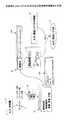
図1は、本発明によるシナリオ生成方法の実施例の概要を示す図である。図1において、検証対象のLSIについての仕様書10が入力として与えられる。この仕様書10は、日本語や英語等の自然言語で記述され、検証対象LSIの機能や構造等を規定したものであり、完成品としての当該LSIが満たしているべき要件を記載したものである。 FIG. 1 is a diagram showing an outline of an embodiment of a scenario generation method according to the present invention. In FIG. 1, a
仕様書10に基づいて、UMLモデル11を作成する。UMLでは、3種類の構造図、5種類の振る舞い図、及び2種類の実装図を用意してあり、これらのダイアグラムを用いて設計対象システムをモデル化することができる。一般に、重要なダイアグラムは3種類であり、構造図のうちのクラス図、及び振る舞い図のうちのシーケンス図とユースケース図とが主に使用される。ユースケース図では、機能を提供するシステム、システムが提供する機能、システムを利用する外部のエンティティ等を部品として表示して、システムの外部から見たときの振る舞いを表現する。クラス図は、対象システムをその構成要素としてのクラス群とクラス間の関係としてモデル化する図である。またシーケンス図は、オブジェクト間のメッセージ送信を時系列表現することにより、各クラスがどのように協調動作するのかというシステムの動的な振る舞いを規定する。ユースケース図、クラス図、シーケンス図等を自然言語で書かれた仕様書から抽出する動作は、人間が人手で行うことになる。 A UML
図1に示すようにクラス図12は、一般にクラス名、属性、及び操作を含む。クラス図12の一番上のボックスは名前コンパートメントと呼ばれ、クラスの名前やクラスの種別が示される。中央のボックスは属性コンパートメントと呼ばれ、そのクラスの属性のリストが含まれる。一番下のボックスは操作コンパートメントと呼ばれ、操作がリストされる。 As shown in FIG. 1, a class diagram 12 generally includes class names, attributes, and operations. The top box of the class diagram 12 is called a name compartment, and indicates the name of the class and the type of class. The middle box is called the attribute compartment and contains a list of attributes for that class. The bottom box is called the operation compartment and lists the operations.
このようにして生成されるUMLのクラス図12から各操作を抽出することで、複数の操作記述13が生成される。この複数の操作記述13の各々が1つの操作に対応する。1つの操作記述13は、対応する操作の名称とともにその制約条件を含む。制約条件には、事前条件、事後条件、及び不変条件が含まれる。 By extracting each operation from the UML class diagram 12 generated in this way, a plurality of
事前条件とは、操作を開始する時に成立している必要がある条件である。例えば録音用LSIの場合、録音操作をするためには、メモリに空き領域があること等が事前条件として必要となる。事後条件とは、操作終了時に実現されているはずの条件である。例えば録音操作を実行した場合、メモリに音声データが格納され始めること等が事後条件として実現される。また不変条件とは、操作を実行している間に不変である成立必要な条件である。例えば、録音操作中には、電源がオンになっている必要があること等が不変条件として必要になる。 The precondition is a condition that needs to be satisfied when the operation is started. For example, in the case of a recording LSI, in order to perform a recording operation, it is necessary as a precondition that there is an empty area in the memory. The post-condition is a condition that should be realized at the end of the operation. For example, when a recording operation is executed, the fact that voice data starts to be stored in the memory is realized as a post-condition. The invariant condition is a necessary condition that is invariant while the operation is being executed. For example, during a recording operation, it is necessary as an invariant condition that the power needs to be turned on.
UMLでは、制約条件の表現のために特定の言語や表記法を指定していない。従って、UMLで抽出された操作についての制約条件は、自然言語で記述されているかも知れないし、或いはOCL(Object Constraint Language)により記述されているかも知れない。OCLはモデル記述のための形式言語であり、モデル要素や関係の間で満たすべき命題を式として定義することができる。本発明では、図1に操作記述例13Aとして示すように、OCLを用いて制約条件を記述することが好ましい。 In UML, a specific language or notation is not specified for expressing the constraint condition. Therefore, the constraint condition for the operation extracted by UML may be described in a natural language or may be described in OCL (Object Constraint Language). OCL is a formal language for model description, and a proposition to be satisfied among model elements and relationships can be defined as an expression. In the present invention, it is preferable to describe constraint conditions using OCL, as shown as operation description example 13A in FIG.
図1の操作記述例13Aにおいて、"context A"は操作Aについての制約条件であることを示す。"pre: B"は、事前条件Bが必要であることを示す。また"post: if C then D else E endif"は、制約Cが真であれば状態Dとなり、さもなければ状態Eとなることを示す。録音用LSIの例であれば、例えば制約「メモリ空き容量無し」が真であれば、「途中で録音中断」という状態となり、さもなければ「録音継続可能」な状態となる、といった事後条件が考えられる。 In the operation description example 13A of FIG. 1, “context A” indicates a restriction condition for the operation A. “pre: B” indicates that the precondition B is necessary. “Post: if C then D else E endif” indicates that the state D is entered if the constraint C is true, and the state E is entered otherwise. In the case of an LSI for recording, for example, if the constraint “no memory free space” is true, the post-condition is such that “recording is interrupted”, and “recording can be continued” otherwise. Conceivable.
次に、複数の操作に一対一に対応する複数の操作記述13から、複数の操作に一対一に対応する複数の操作記述関係式14を生成する。この操作記述関係式は、「ある前提条件の下である操作を実行すると、ある制約の下である出力が得られる」等の当該操作の入力と出力との関係を述語論理で記述した論理式である。図1に示す操作記述関係式例14Aでは、"(A and B)"はAとBとが成立していること、即ち事前条件Bの下で操作Aが実行されたことを示し、その結果("=>")、"(if C then D else E endif)"という命題が真になることが記述されている。即ち、事前条件Bの下で操作Aが実行されると、制約Cが真であれば状態Dとなり、さもなければ状態Eとなることが示されている。 Next, a plurality of operation description relational expressions 14 corresponding one-to-one with a plurality of operations are generated from a plurality of
このような操作記述関係式14を各操作に対して生成する動作は自動的(機械的)に実行することができる。即ち、操作記述13をコンピュータにより解析・処理することにより、操作記述関係式14を自動的に生成することができる。但し自動生成のためには、制約条件がOCL等により記述されていることが必要であり、もし制約条件が自然言語で記述されている場合には、予めOCL等による記述に変更しておく必要がある。 The operation for generating such an operation description relational expression 14 for each operation can be automatically (mechanically) executed. That is, the operation description relational expression 14 can be automatically generated by analyzing and processing the
次に、各操作に対して一対一に生成された操作記述関係式14に基づいて、各操作記述関係式に一対一に対応する原因結果グラフ15を生成する。原因結果グラフ15は、「ある前提条件の下である操作を実行すると、ある制約の下である出力が得られる」等の原因と結果との関係を表す有向グラフである。 Next, based on the operation description relational expression 14 generated one-on-one for each operation, a cause-and-
更に複数の原因結果グラフ15同士を結合することで、結合された原因結果グラフ15を生成する。例えば、「ある前提条件の下で第1の操作を実行すると、ある制約の下で第1の出力が得られる」ことを表現する原因結果グラフ15と、「第1の出力を前提条件として第2の操作を実行すると、第2の出力が得られる」ことを表現する原因結果グラフ15とには、第1の出力が共通の構成要素として現れるので、これら2つの原因結果グラフ15を結合できることが分かる。そこで、これら2つの原因結果グラフ15を結合して、「ある前提条件の下で第1の操作を実行すると、ある制約の下で第1の出力が得られ、更にこの第1の出力を前提条件として第2の操作を実行すると、第2の出力が得られる」という複数の操作にまたがる原因と結果との関係を表すグラフが得られる。なおビジュアルなダイアグラムとして表現した場合に、原因結果グラフ15は図1に示すようなノードと矢印とで構成されたグラフとなる。 Further, a plurality of cause /
操作記述関係式14から原因結果グラフ15を生成し更に結合する動作は、コンピュータにより自動的(機械的)に実行することができる。具体的には、ある原因結果グラフ15のある1つのノード(例えば事前条件)に着目して、そのノードが他の原因結果グラフ15に現れるか否かを他の全ての原因結果グラフ15について検索して、その要素が現れる原因結果グラフ15が見つかった場合には、その見つかった原因結果グラフ15を着目原因結果グラフ15に結合すればよい。この際、組み合わせには後述するように6つのパターンが存在する。着目する要素を順次次の要素に替えていき、更に着目する原因結果グラフを順次次の原因結果グラフに替えていくことにより、全ての操作の全ての組み合わせを包含した原因結果グラフ15の集合を生成することができる。最終的に生成された原因結果グラフ15の集合においては、単一の操作に対応する最小単位の原因結果グラフ15がそのまま含まれていてもよい。 The operation of generating the cause /
このように、仕様書から抽出された全ての操作に対応する全ての操作記述関係式14に対して、全ての可能な(意味のある)組み合わせを生成することで、全てのシナリオを含む原因結果グラフ15の集合が作成される。ここで、1つの操作記述関係式14に対応する1つの原因結果グラフ15は制約条件の下での入出力間の関係を規定したものであるので、入力と出力との関係はシナリオの一部として意味のある関係となっている。従って、複数の原因結果グラフ15を組み合わせて生成した原因結果グラフ15についても、原因と結果との関係は制約条件を満たす条件下で成立する関係であり、シナリオとして意味のある関係となっている。 In this way, by generating all possible (meaningful) combinations for all the operation description relational expressions 14 corresponding to all the operations extracted from the specification, the causal result including all the scenarios. A set of
最後に、所望の検証シナリオ(所望の結果に帰結するようなシナリオ)を得るために、検証シナリオ制約16を入力する。この検証シナリオ制約16は、所望の結果を表現したものである。検証シナリオ制約16に至るような一連の操作を、原因結果グラフ15の集合中から検索して取り出すことで、所望の検証シナリオ17を得ることができる。 Finally, in order to obtain a desired verification scenario (a scenario that results in a desired result), a verification scenario constraint 16 is input. The verification scenario constraint 16 represents a desired result. A desired
録音用LSIの例の場合、検証シナリオ制約16としては、例えば「途中不要部分を除いた録音データ」である。「途中不要部分を除いた録音データ」という状態が真となるような原因結果グラフ15を検索して抽出することで、例えば「録音操作を実行し、一時停止操作を実行し、一時停止操作をリセットし、その後録音停止動作を実行する」といった検証シナリオを抽出することができる。 In the case of an example of a recording LSI, the verification scenario constraint 16 is, for example, “recording data excluding unnecessary portions on the way”. By searching and extracting the cause /
図2は、操作記述13と原因結果グラフ15との関係を示す図である。図2にはある操作に対する操作記述13を示し、またその操作記述13に対応する原因結果グラフ15を示す。操作記述13は、例えば操作13−1と、事前条件13−2と、事後条件13−3を含む。操作13−1は操作名を指定し、事前条件13−2は前提条件を指定し、事後条件13−3には制約と出力結果とが指定される。 FIG. 2 is a diagram showing the relationship between the
操作13−1に指定される操作名が操作名21として、原因結果グラフ15の1構成要素となる。また事前条件13−2に指定される前提条件が前提条件22として、原因結果グラフ15の1構成要素となる。また事後条件13−3に指定される制約と出力結果とがそれぞれ制約23と出力結果24として、原因結果グラフ15の構成要素となる。これら構成要素(ノード)間を、図示のように入力側(操作名、前提条件、制約)から出力側(出力結果)に向かう矢印で結合する。このようにして、操作記述13(又は操作記述関係式14)を原因結果グラフ15として表すことができる。 The operation name specified in the operation 13-1 is one component of the cause /
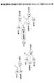
図3乃至図8は、操作記述関係式14を結合する際の6通りの組み合わせについて説明するための図である。 FIGS. 3 to 8 are diagrams for explaining the six combinations when combining the operation description relational expressions 14.
図3において、第1の操作31は、操作名A、前提条件B、及び出力結果Cにより表される。また第2の操作32は、操作名D、前提条件C、及び出力結果Eにより表される。この場合、第1の操作31の出力結果Cと第2の操作32の前提条件Cとがともに内容がCであり一致する。なお内容が一致するとは、そのカテゴリが操作名であるか、前提条件であるか、制約であるか、或いは出力結果であるかに関わらず、その実体的な内容が同一であることである。 In FIG. 3, the first operation 31 is represented by an operation name A, a precondition B, and an output result C. The second operation 32 is represented by an operation name D, a precondition C, and an output result E. In this case, the output result C of the first operation 31 and the precondition C of the second operation 32 are both in content and match. Note that the contents match means that the substantive contents are the same regardless of whether the category is an operation name, a precondition, a restriction, or an output result.
従って、第1の操作31の出力結果Cと第2の操作32の前提条件Cとを結合して1つのノードとすることで、結合された原因結果グラフ33を生成することができる。この原因結果グラフ33は、前提条件Bの下で操作名Aの操作を実行すると、出力結果Cが得られ、更にこの出力結果Cを前提条件として操作名Dの操作を実行すると、出力結果Eが得られることを示す。 Therefore, by combining the output result C of the first operation 31 and the precondition C of the second operation 32 into one node, the combined cause / result graph 33 can be generated. In the cause / result graph 33, when the operation with the operation name A is executed under the precondition B, an output result C is obtained. When the operation with the operation name D is further executed with the output result C as a precondition, the output result E Is obtained.
図4において、第1の操作34は、操作名A、前提条件B、制約F、及び出力結果Cにより表される。また第2の操作35は、操作名D、前提条件F、及び出力結果Eにより表される。この場合、第1の操作34の制約Fと第2の操作35の前提条件Fとがともに内容がFであり一致する。 In FIG. 4, the first operation 34 is represented by an operation name A, a precondition B, a constraint F, and an output result C. The second operation 35 is represented by an operation name D, a precondition F, and an output result E. In this case, both the constraint F of the first operation 34 and the precondition F of the second operation 35 are F and match.
従って、第1の操作34の制約Fと第2の操作35の前提条件Fとを結合して1つのノードとすることで、結合された原因結果グラフ36を生成することができる。この原因結果グラフ36は、前提条件Bの下で操作名Aの操作を実行すると、制約Fが真の場合に出力結果Cが得られ、更に前提条件Fとして操作名Dの操作を実行すると、出力結果Eが得られることを示す。 Therefore, by combining the constraint F of the first operation 34 and the precondition F of the second operation 35 into one node, the combined cause / result graph 36 can be generated. In the cause / result graph 36, when the operation of the operation name A is executed under the precondition B, an output result C is obtained when the constraint F is true. Further, when the operation of the operation name D is executed as the precondition F, The output result E is obtained.
図5において、第1の操作37は、操作名A、前提条件B、及び出力結果Cにより表される。また第2の操作38は、操作名D、前提条件B、及び出力結果Eにより表される。この場合、第1の操作37の前提条件Bと第2の操作38の前提条件Bとがともに内容がBであり一致する。 In FIG. 5, the first operation 37 is represented by an operation name A, a precondition B, and an output result C. The second operation 38 is represented by an operation name D, a precondition B, and an output result E. In this case, both the precondition B of the first operation 37 and the precondition B of the second operation 38 are B and match.
従って、第1の操作37の前提条件Bと第2の操作38の前提条件Bとを結合して1つのノードとすることで、結合された原因結果グラフ39を生成することができる。この原因結果グラフ39は、前提条件Bの下で操作名Aの操作を実行すると、出力結果Cが得られ、また前提条件Bの下で操作名Dの操作を実行すると、出力結果Eが得られることを示す。 Therefore, by combining the precondition B of the first operation 37 and the precondition B of the second operation 38 into one node, a combined cause / result graph 39 can be generated. In the cause / result graph 39, an output result C is obtained when the operation with the operation name A is executed under the precondition B, and an output result E is obtained when the operation with the operation name D is executed under the precondition B. Indicates that
図6において、第1の操作41は、操作名A、前提条件B、及び出力結果Cにより表される。また第2の操作42は、操作名D、前提条件F、制約C、及び出力結果Eにより表される。この場合、第1の操作41の出力結果Cと第2の操作42の制約Cとがともに内容がCであり一致する。 In FIG. 6, the first operation 41 is represented by an operation name A, a precondition B, and an output result C. The second operation 42 is represented by an operation name D, a precondition F, a constraint C, and an output result E. In this case, the output result C of the first operation 41 and the constraint C of the second operation 42 are both in content and match.
従って、第1の操作41の出力結果Cと第2の操作42の制約Cとを結合して1つのノードとすることで、結合された原因結果グラフ43を生成することができる。この原因結果グラフ43は、前提条件Bの下で操作名Aの操作を実行すると、出力結果Cが得られ、更に前提条件Fの下で操作名Dの操作を実行すると、上記出力結果Cが制約として真である場合に、出力結果Eが得られることを示す。 Therefore, by combining the output result C of the first operation 41 and the constraint C of the second operation 42 into one node, a combined cause / result graph 43 can be generated. In the cause / result graph 43, when an operation with the operation name A is executed under the precondition B, an output result C is obtained. When an operation with the operation name D is further executed under the precondition F, the output result C is obtained. When the constraint is true, the output result E is obtained.
図7において、第1の操作44は、操作名A、前提条件B、制約G、及び出力結果Cにより表される。また第2の操作45は、操作名D、前提条件F、制約G、及び出力結果Eにより表される。この場合、第1の操作44の制約Gと第2の操作42の制約Gとがともに内容がGであり一致する。 In FIG. 7, the first operation 44 is represented by an operation name A, a precondition B, a constraint G, and an output result C. The second operation 45 is represented by an operation name D, a precondition F, a constraint G, and an output result E. In this case, both the constraint G of the first operation 44 and the constraint G of the second operation 42 are G and match.
従って、第1の操作44の制約Gと第2の操作45の制約Gとを結合して1つのノードとすることで、結合された原因結果グラフ46を生成することができる。この原因結果グラフ46は、前提条件Bの下で操作名Aの操作を実行すると、制約Gが真である場合に出力結果Cが得られ、更に前提条件Fの下で操作名Dの操作を実行すると、上記制約Gが真である場合に出力結果Eが得られることを示す。 Therefore, by combining the constraint G of the first operation 44 and the constraint G of the second operation 45 into one node, the combined cause / result graph 46 can be generated. In the cause / result graph 46, when the operation of the operation name A is executed under the precondition B, an output result C is obtained when the constraint G is true, and the operation of the operation name D is further performed under the precondition F. When executed, it indicates that an output result E is obtained when the constraint G is true.
図8において、第1の操作47は、操作名A、前提条件B、及び出力結果Cにより表される。また第2の操作48は、操作名D、前提条件F、制約B、及び出力結果Eにより表される。この場合、第1の操作47の前提条件Bと第2の操作48の制約Bとがともに内容がBであり一致する。 In FIG. 8, the first operation 47 is represented by an operation name A, a precondition B, and an output result C. The second operation 48 is represented by an operation name D, a precondition F, a constraint B, and an output result E. In this case, both the precondition B of the first operation 47 and the constraint B of the second operation 48 are B and match.
従って、第1の操作47の前提条件Bと第2の操作48の制約Bとを結合して1つのノードとすることで、結合された原因結果グラフ49を生成することができる。この原因結果グラフ49は、前提条件Bの下で操作名Aの操作を実行すると、出力結果Cが得られ、更に前提条件Fの下で操作名Dの操作を実行すると、上記前提条件Bが制約として真である場合に、出力結果Eが得られることを示す。 Therefore, by combining the precondition B of the first operation 47 and the constraint B of the second operation 48 into one node, a combined cause /
2つの原因結果グラフ15を組み合わせて1つの大きな原因結果グラフ15を生成する場合、上に示したように図3乃至図8の6つのパターンのみが存在する。これらの6つのパターンに従って原因結果グラフ15を組み合わせて大きな原因結果グラフ15を作成していくことで、意味のあるシナリオに対応する原因結果グラフ15の集合を生成することができる。 When the two cause /
図9は、原因結果グラフからシナリオを抽出する処理について説明するための図である。図9に示す例において、原因結果グラフ15は、操作A、前提条件B、出力結果且つ前提条件C、操作D、制約且つ前提条件E、出力結果F、操作G、及び出力結果Hから構成される。このような原因結果グラフ15が得られている状態で、シナリオ制約16Aが指定される。 FIG. 9 is a diagram for explaining a process of extracting a scenario from the cause / result graph. In the example shown in FIG. 9, the cause /
シナリオ制約16Aは、「出力結果Fが真(=1)」を要求するものであり、この要求に従って出力結果Fが真となるようなシナリオが生成される。この例の場合、検証シナリオ17Aとしては、まず操作Aを実行しその後に操作Dを実行するという一連の操作が抽出される。 The
図10は、原因結果グラフからシナリオを抽出する処理について説明するための図である。図10に示す例において、原因結果グラフ15は、操作A、前提条件B、出力結果且つ前提条件C、操作D、制約且つ前提条件E、出力結果F、操作G、及び出力結果Hから構成される。このような原因結果グラフ15が得られている状態で、シナリオ制約16Bが指定される。 FIG. 10 is a diagram for explaining a process of extracting a scenario from the cause / result graph. In the example illustrated in FIG. 10, the cause /
シナリオ制約16Bは、「出力結果Fが真(=1)且つ出力結果Hが真(=1)」を要求するものであり、この要求に従って出力結果Fが真となり且つ出力結果Hが真となるようなシナリオが生成される。この例の場合、検証シナリオ17Bとしては、まず操作Aを実行しその後に操作Dを実行するという一連の操作と、操作Gを実行するという操作が抽出される。なお図10において検証シナリオ17Bの操作Gは、操作A及び操作Dの一連の操作とは独立に図示されているが、これは、操作Gと、操作A及び操作Dとの時間的な前後関係には何ら制限がないためである。即ち、操作Gは、操作A及び操作Dとは独立に任意のタイミングで実行することができる。それに対して、操作Dは操作Aの後に実行されなければならない。これは操作Aの出力結果Cを前提条件として操作Dを実行する必要があるからである。 The scenario constraint 16B requires that “the output result F is true (= 1) and the output result H is true (= 1)”. According to this request, the output result F becomes true and the output result H becomes true. Such a scenario is generated. In this example, as the verification scenario 17B, a series of operations in which the operation A is first executed and then the operation D is executed, and an operation in which the operation G is executed are extracted. In FIG. 10, the operation G of the
図9及び図10に示すような検証シナリオの抽出は、シナリオ制約が要求する条件(例えば出力結果Fが真という条件)を示すノードから、原因結果グラフ15を遡っていけばよい。即ち、出力結果Fを得るためには、操作Dを前提条件Cの下で実行する必要があり、前提条件Cを満足させるためには、操作Aを実行する必要があることが分かる。このようにして、操作Aを実行してその後に操作Dを実行するというシナリオを抽出することができる。 The verification scenario as shown in FIGS. 9 and 10 may be extracted by going back to the cause /
このような検証シナリオの抽出は、二分決定グラフ(Binary Decision Diagram)を利用して実行することができる。BDDでは、論理関数が充足可能かどうかを直ちに判定することが可能である。またその論理関数が充足可能である場合には、論理関数の値を1にするような入力値を求めることができる。従って、原因結果グラフ15をBDDで表現すれば、検証シナリオの抽出作業はBDDにおける充足可能判定問題となり、コンピュータにより自動的(機械的)に容易に実行することができる。 Extraction of such a verification scenario can be executed using a binary decision diagram. In BDD, it is possible to immediately determine whether a logical function can be satisfied. If the logical function can be satisfied, an input value that makes the value of the
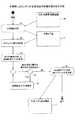
図11は、本発明によるシナリオ生成方法の処理の流れを示す図である。まずステップS1で、仕様書10を分析する。前述のように仕様書10は自然言語で記述されたものであるので、これを分析して、UML等の系統的な仕様記述言語で記述した仕様モデル11を生成する。この部分は、人手による作業である。これ以降のステップは、コンピュータにより自動的に実行するステップである。 FIG. 11 is a diagram showing the flow of processing of the scenario generation method according to the present invention. First, in step S1, the
ステップS2において仕様モデル11から操作を抽出する。前述のように操作記述には、対応する操作の名称とともにその制約条件を含む。操作記述は、所定の記述言語(例えばOCL)により記述される。 In step S2, an operation is extracted from the
ステップS3において、全ての操作に対して原因結果グラフを作成する。具体的には、全ての操作記述から操作記述関係式を介して原因結果グラフを生成する。 In step S3, a cause / result graph is created for all operations. Specifically, a cause / result graph is generated from all operation descriptions via an operation description relational expression.
ステップS4において、複数の原因結果グラフのうちで結合可能な操作の組み合わせがあるか否かを判定する。判定結果がyesの場合、ステップS5で結合可能な操作に対応する複数の原因結果グラフ同士を結合する。この結合の仕方には、図3乃至図8に説明した6通りのパターンのみが存在する。その後、ステップS4に戻り、結合可能か否かの判定と結合作業とを繰り返す。 In step S4, it is determined whether or not there is a combination of operations that can be combined among the plurality of cause / effect graphs. If the determination result is yes, a plurality of cause / result graphs corresponding to the operations that can be combined in step S5 are combined. There are only the six patterns described in FIGS. 3 to 8 in this coupling method. Thereafter, the process returns to step S4, and the determination of whether or not the connection is possible and the combination work are repeated.
ステップS4における結合可能判定の結果がno(結合可能な原因結果グラフが存在しない)場合には、ステップS6に進む。ステップS6では、二分決定グラフ法を用いてシナリオを生成する。即ち図9及び図10において説明したように、検証シナリオ制約が真になるような原因結果グラフの入力値を特定することにより、検証シナリオを構成する一連の操作を抽出する。全ての所望の検証シナリオ制約に対して、対応する一連の操作を原因結果グラフから抽出することで、検証シナリオの集合17が得られる。 If the result of the join possibility determination in step S4 is no (no cause result graph that can be joined exists), the process proceeds to step S6. In step S6, a scenario is generated using the binary decision graph method. That is, as described with reference to FIGS. 9 and 10, a series of operations constituting the verification scenario is extracted by specifying the input value of the cause / result graph such that the verification scenario constraint becomes true. A set of
なお上記説明において、複数の操作の結合処理は、複数の原因結果グラフを結合することにより実現している。しかし複数の操作の結合処理は、原因結果グラフの段階で必ずしも実行する必要はなく、可能であれば操作記述の段階或いは操作記述関係式の段階で実行してもよい。 In the above description, the combination processing of a plurality of operations is realized by combining a plurality of cause / effect graphs. However, the combination processing of a plurality of operations is not necessarily executed at the stage of the cause / result graph, and may be executed at the stage of the operation description or the stage of the operation description relational expression if possible.
このようにして検証シナリオの集合17が得られると、各検証シナリオを用いて対象LSIの機能の検証を行うことができる。例えば実装レベルでの検証であれば、LSIテスタを制御するホストコンピュータに各検証シナリオを読み込み、LSIテスタを用いて検証対象LSIを検証シナリオ通りに動作させ、LSIの動作が期待通りであるか否か、即ちLSIの機能が正常であるか否かをテストすることができる。 When the verification scenario set 17 is obtained in this manner, the function of the target LSI can be verified using each verification scenario. For example, in the case of verification at the mounting level, each verification scenario is read into the host computer that controls the LSI tester, and the verification target LSI is operated according to the verification scenario using the LSI tester. That is, it is possible to test whether or not the function of the LSI is normal.
図12は、本発明によるシナリオ生成方法を実行する装置の構成を示す図である。 FIG. 12 is a diagram showing the configuration of an apparatus for executing the scenario generation method according to the present invention.
図12に示されるように、本発明によるシナリオ生成方法を実行する装置は、例えばパーソナルコンピュータやエンジニアリングワークステーション等のコンピュータにより実現される。図12の装置は、コンピュータ510と、コンピュータ510に接続されるディスプレイ装置520、通信装置523、及び入力装置よりなる。入力装置は、例えばキーボード521及びマウス522を含む。コンピュータ510は、CPU511、RAM512、ROM513、ハードディスク等の二次記憶装置514、可換媒体記憶装置515、及びインターフェース516を含む。 As shown in FIG. 12, the apparatus for executing the scenario generation method according to the present invention is realized by a computer such as a personal computer or an engineering workstation. 12 includes a
キーボード521及びマウス522は、ユーザとのインターフェースを提供するものであり、コンピュータ510を操作するための各種コマンドや要求されたデータに対するユーザ応答等が入力される。ディスプレイ装置520は、コンピュータ510で処理された結果等を表示すると共に、コンピュータ510を操作する際にユーザとの対話を可能にするために様々なデータ表示を行う。通信装置523は、遠隔地との通信を行なうためのものであり、例えばモデムやネットワークインターフェース等よりなる。 The
本発明によるシナリオ生成方法は、コンピュータ510が実行可能なコンピュータプログラムとして提供される。このコンピュータプログラムは、可換媒体記憶装置515に装着可能な記憶媒体Mに記憶されており、記憶媒体Mから可換媒体記憶装置515を介して、RAM512或いは二次記憶装置514にロードされる。或いは、このコンピュータプログラムは、遠隔地にある記憶媒体(図示せず)に記憶されており、この記憶媒体から通信装置523及びインターフェース516を介して、RAM512或いは二次記憶装置514にロードされる。 The scenario generation method according to the present invention is provided as a computer program executable by the
キーボード521及び/又はマウス522を介してユーザからプログラム実行指示があると、CPU511は、記憶媒体M、遠隔地記憶媒体、或いは二次記憶装置514からプログラムをRAM512にロードする。CPU511は、RAM512の空き記憶空間をワークエリアとして使用して、RAM512にロードされたプログラムを実行し、適宜ユーザと対話しながら処理を進める。なおROM513は、コンピュータ510の基本動作を制御するための制御プログラムが格納されている。 When there is a program execution instruction from the user via the
上記コンピュータプログラムを実行することにより、コンピュータ510が、上記各実施例で説明されたようにシナリオ生成方法を実行する。 By executing the computer program, the
以上、本発明を実施例に基づいて説明したが、本発明は上記実施例に限定されるものではなく、特許請求の範囲に記載の範囲内で様々な変形が可能である。 As mentioned above, although this invention was demonstrated based on the Example, this invention is not limited to the said Example, A various deformation | transformation is possible within the range as described in a claim.
10 仕様書
11 UMLモデル
12 クラス図
13 操作記述
14 操作記述関係式
15 原因結果グラフ
16 検証シナリオ制約
17 検証シナリオ
510 コンピュータ
511 CPU
512 RAM
513 ROM
514 二次記憶装置
515 可換媒体記憶装置
516 インターフェース
520 ディスプレイ装置
521 キーボード
522 マウス
523 通信装置10
512 RAM
513 ROM
514
Claims (6)
Translated fromJapanese該複数の操作にそれぞれ対応し各々が操作名と制約条件とを含む複数の操作記述を生成し、
該複数の操作記述に基づいて該複数の操作を結合した少なくとも1つの原因結果グラフを生成し、
該原因結果グラフから一連の操作をシナリオとして抽出する
各段階を含み、
該制約条件は、該操作名の操作を開始する時に成立している必要がある条件である事前条件、該操作名の操作を終了する時に実現されているはずの条件である事後条件を少なくとも含み、該各段階をコンピュータが実行することを特徴とするシナリオ生成方法。Extract multiple operations froma specification modelthat describes the specification in a given description language ,
A plurality of operation descriptions each corresponding to the plurality of operations and including an operation name and a constraint condition are generated,
Generating at least one causal result graph obtained by combining the plurality of operations based on the plurality of operation descriptions;
Look including the stages of extracting a series of operations as a scenario from the cause-effectgraph,
The constraint condition includes at least a precondition that is a condition that must be satisfied when the operation of the operation name is started, and a postcondition that is a condition that should be realized when the operation of the operation name is ended. A scenario generation method, wherein thecomputer executes each of the steps .
該複数の操作記述にそれぞれ対応する複数の原因結果グラフを生成し、
該複数の原因結果グラフ同士を結合して該少なくとも1つの原因結果グラフを生成する
段階を含み、該複数の原因結果グラフは操作名、前提条件、制約、及び出力結果を含み、第1の原因結果グラフの操作名、前提条件、制約、及び出力結果の少なくとも何れか1つの内容が、第2の原因結果グラフの操作名、前提条件、制約、及び出力結果の少なくとも何れか1つの内容と一致する場合に、該一致する内容を共有させることにより該第1の原因結果グラフと該第2の原因結果グラフとを結合することを特徴とする請求項1記載のシナリオ生成方法。The step of generating the cause-effect graph includes
Generating a plurality of cause / effect graphs corresponding to the plurality of operation descriptions,
Combining the plurality of cause-and-effect graphs to generate the at least one cause-and-effect graph, the plurality of cause-and-result graphs including operation names, preconditions, constraints, and output results, and a first cause At least one of the operation name, precondition, constraint, and output result of the result graph matches the content of at least one of the operation name, precondition, constraint, and output result of the second cause / result graph 2. The scenario generation method according to claim 1, wherein the first cause-result graph and the second cause-result graph are combined by sharing the matching contents.
該複数の操作にそれぞれ対応し各々が操作名と制約条件とを含む複数の操作記述を生成し、
該複数の操作記述に基づいて該複数の操作を結合した少なくとも1つの原因結果グラフを生成し、
該原因結果グラフから一連の操作をシナリオとして抽出する
各段階をコンピュータが実行するように該コンピュータを制御し、該制約条件は、該操作名の操作を開始する時に成立している必要がある条件である事前条件、該操作名の操作を終了する時に実現されているはずの条件である事後条件を少なくとも含むことを特徴とするシナリオ生成プログラム。Extract multiple operations from a specification model written in a given description language,
A plurality of operation descriptions each corresponding to the plurality of operations and including an operation name and a constraint condition are generated,
Generating at least one causal result graph obtained by combining the plurality of operations based on the plurality of operation descriptions;
Thecomputer is controlled so that each stage of extracting a series of operations as a scenario from the cause-result graphis executed by the computer, and the constraint condition must be satisfied when starting the operation of the operation name And a post-condition that is a condition that should be realized when the operation with the operation name is terminated .
該メモリの該プログラムを実行して該メモリの該仕様モデルを処理する処理ユニット
を含み、該処理ユニットは、
該仕様モデルから複数の操作を抽出し、
該複数の操作にそれぞれ対応し各々が操作名と制約条件とを含む複数の操作記述を生成し、
該複数の操作記述に基づいて該複数の操作を結合した少なくとも1つの原因結果グラフを生成し、
該原因結果グラフから一連の操作をシナリオとして抽出する
各段階を実行し、該制約条件は、該操作名の操作を開始する時に成立している必要がある条件である事前条件、該操作名の操作を終了する時に実現されているはずの条件である事後条件を少なくとも含むことを特徴とするシナリオ生成装置。A memory for storing a program and a specification model described in a predetermined description language;
A processing unit that executes the program of the memory to process the specification model of the memory, the processing unit comprising:
Extract multiple operations from the specification model,
A plurality of operation descriptions each corresponding to the plurality of operations and including an operation name and a constraint condition are generated,
Generating at least one causal result graph obtained by combining the plurality of operations based on the plurality of operation descriptions;
Each stage of extracting a series of operations as a scenario from the cause-result graph is executed,and the constraint condition is a precondition that is a condition that must be satisfied when the operation of the operation name is started. A scenario generation device characterized byincluding at least a postcondition which is a condition that should be realized when an operation is finished .
Priority Applications (2)
| Application Number | Priority Date | Filing Date | Title |
|---|---|---|---|
| JP2006080801AJP4445480B2 (en) | 2006-03-23 | 2006-03-23 | Scenario generation method, scenario generation program, and scenario generation device |
| US11/543,025US7904843B2 (en) | 2006-03-23 | 2006-10-05 | Systematic generation of scenarios from specification sheet |
Applications Claiming Priority (1)
| Application Number | Priority Date | Filing Date | Title |
|---|---|---|---|
| JP2006080801AJP4445480B2 (en) | 2006-03-23 | 2006-03-23 | Scenario generation method, scenario generation program, and scenario generation device |
Publications (2)
| Publication Number | Publication Date |
|---|---|
| JP2007257291A JP2007257291A (en) | 2007-10-04 |
| JP4445480B2true JP4445480B2 (en) | 2010-04-07 |
Family
ID=38631474
Family Applications (1)
| Application Number | Title | Priority Date | Filing Date |
|---|---|---|---|
| JP2006080801AExpired - Fee RelatedJP4445480B2 (en) | 2006-03-23 | 2006-03-23 | Scenario generation method, scenario generation program, and scenario generation device |
Country Status (2)
| Country | Link |
|---|---|
| US (1) | US7904843B2 (en) |
| JP (1) | JP4445480B2 (en) |
Families Citing this family (17)
| Publication number | Priority date | Publication date | Assignee | Title |
|---|---|---|---|---|
| US7490295B2 (en) | 2004-06-25 | 2009-02-10 | Apple Inc. | Layer for accessing user interface elements |
| EP1770562A4 (en)* | 2004-07-01 | 2009-08-26 | Fujitsu Ltd | AUDIT ASSISTING DEVICE, AUDIT ASSISTING METHOD, AUDIT ASSISTING PROGRAM, AND RECORDING MEDIUM |
| JP5125385B2 (en)* | 2007-10-10 | 2013-01-23 | 富士通株式会社 | Verification scenario creation program, recording medium recording the program, verification scenario creation device, and verification scenario creation method |
| US8352148B2 (en)* | 2008-05-21 | 2013-01-08 | General Electric Company | System for controlling input profiles of combined cycle power generation system |
| JP2010009384A (en)* | 2008-06-27 | 2010-01-14 | Fujitsu Ltd | Verification support program, verification support apparatus and verification support method |
| JP5067317B2 (en)* | 2008-08-27 | 2012-11-07 | 富士通株式会社 | Verification support program, verification support apparatus, and verification support method |
| US8365112B2 (en) | 2009-09-04 | 2013-01-29 | Fujitsu Limited | Verification apparatus and design verification program |
| WO2011057026A2 (en)* | 2009-11-05 | 2011-05-12 | Aptima, Inc. | Systems and methods to define and monitor a scenario of conditions |
| JP5691743B2 (en)* | 2011-03-30 | 2015-04-01 | 富士通株式会社 | Mounting design support program, method and apparatus |
| US10179287B2 (en) | 2011-05-09 | 2019-01-15 | Aptima, Inc. | Systems and methods for scenario generation and monitoring |
| JP6102448B2 (en)* | 2013-04-10 | 2017-03-29 | 富士通株式会社 | Verification support program, verification support apparatus, and verification support method |
| JP6213019B2 (en)* | 2013-07-30 | 2017-10-18 | 富士通株式会社 | Sequence extraction method, sequence extraction program, and sequence extraction device |
| WO2015040735A1 (en)* | 2013-09-20 | 2015-03-26 | 株式会社日立製作所 | Formal verification assistance device for software specifications and method thereof |
| US9892027B2 (en)* | 2014-07-09 | 2018-02-13 | Fujitsu Limited | Event-driven software testing |
| US10073763B1 (en)* | 2017-12-27 | 2018-09-11 | Accenture Global Solutions Limited | Touchless testing platform |
| WO2021059521A1 (en)* | 2019-09-27 | 2021-04-01 | 日本電気株式会社 | Analysis system, method, and program |
| JP7522697B2 (en) | 2021-04-21 | 2024-07-25 | 日立Astemo株式会社 | Test case verification device and test case verification method |
Family Cites Families (15)
| Publication number | Priority date | Publication date | Assignee | Title |
|---|---|---|---|---|
| US5249151A (en)* | 1990-06-05 | 1993-09-28 | Fmc Corporation | Multi-body mechanical system analysis apparatus and method |
| JPH08235024A (en) | 1995-02-28 | 1996-09-13 | Toshiba Corp | Automatic test device for software |
| US5892947A (en)* | 1996-07-01 | 1999-04-06 | Sun Microsystems, Inc. | Test support tool system and method |
| GB9805260D0 (en)* | 1998-03-13 | 1998-05-06 | Ncr Int Inc | Method and apparatus to model the variables of a data set |
| US6789054B1 (en)* | 1999-04-25 | 2004-09-07 | Mahmoud A. Makhlouf | Geometric display tools and methods for the visual specification, design automation, and control of adaptive real systems |
| US7099809B2 (en)* | 2000-05-04 | 2006-08-29 | Dov Dori | Modeling system |
| JP2002297412A (en) | 2001-03-30 | 2002-10-11 | Fujitsu Ltd | Hardware test item generating method |
| US20030046029A1 (en)* | 2001-09-05 | 2003-03-06 | Wiener Jay Stuart | Method for merging white box and black box testing |
| US20040034543A1 (en)* | 2002-01-15 | 2004-02-19 | Koninklijke Ahold Nv | Methodology to design, construct, and implement human resources business procedures and processes |
| US7107191B2 (en)* | 2002-05-02 | 2006-09-12 | Microsoft Corporation | Modular architecture for optimizing a configuration of a computer system |
| US7512912B1 (en)* | 2003-08-16 | 2009-03-31 | Synopsys, Inc. | Method and apparatus for solving constraints for word-level networks |
| CN101694643B (en)* | 2003-09-30 | 2012-10-10 | 明导公司 | System verification using one or more automata |
| US20070074180A1 (en)* | 2003-12-22 | 2007-03-29 | Nasa Hq's | Systems, Methods and Apparatus for Procedure Development and Verification |
| US7260501B2 (en)* | 2004-04-21 | 2007-08-21 | University Of Connecticut | Intelligent model-based diagnostics for system monitoring, diagnosis and maintenance |
| US7275231B2 (en)* | 2004-09-15 | 2007-09-25 | Fujitsu Limited | High level validation of designs and products |
- 2006
- 2006-03-23JPJP2006080801Apatent/JP4445480B2/ennot_activeExpired - Fee Related
- 2006-10-05USUS11/543,025patent/US7904843B2/ennot_activeExpired - Fee Related
Also Published As
| Publication number | Publication date |
|---|---|
| US20070261012A1 (en) | 2007-11-08 |
| US7904843B2 (en) | 2011-03-08 |
| JP2007257291A (en) | 2007-10-04 |
Similar Documents
| Publication | Publication Date | Title |
|---|---|---|
| JP4445480B2 (en) | Scenario generation method, scenario generation program, and scenario generation device | |
| CN111694741B (en) | Test case design method based on path depth coverage | |
| JP2862886B2 (en) | Computer-aided design system for ASIC | |
| JP4255079B2 (en) | Assertion generation system, circuit verification system, program, and assertion generation method | |
| WO2012032890A1 (en) | Source code conversion method and source code conversion program | |
| US20070276644A1 (en) | Conversion of circuit description to a transaction model | |
| Oh et al. | Software safety analysis of function block diagrams using fault trees | |
| Provost et al. | A formal semantics for Grafcet specifications | |
| JP4978233B2 (en) | Simulator development system and simulator development method | |
| US20170300305A1 (en) | Executable guidance experiences based on implicitly generated guidance models | |
| Saadatpoor et al. | State based control of timed discrete event systems using binary decision diagrams | |
| JP6279750B2 (en) | Source code equivalence verification device | |
| JP2008305079A (en) | Requirement specification automatic verification method | |
| Kugler et al. | Testing scenario-based models | |
| JP7233611B2 (en) | Manufacturing system design verification device | |
| ter Beek et al. | Software product line analysis with mCRL2 | |
| CN115509510A (en) | Visual human-computer interaction software modeling method and device based on LIDL | |
| JP2007011605A (en) | Software operation specification model checking support device, model checking system including the same, and model checking support program | |
| JP4481783B2 (en) | Simulation model creation device, simulation device and system, method and program | |
| CN113642148B (en) | A modeling language representation method based on equation description | |
| JP2009237913A (en) | Property extraction device and method | |
| WO2009101934A1 (en) | System for verifying lsi design, method for verifying lsi design, and program therefor | |
| KR102870245B1 (en) | Software modelling apparatus for electric field control device for urban railway and method using the same | |
| JP5901465B2 (en) | Procedure manual generation apparatus, procedure manual generation method and program | |
| JP5875607B2 (en) | Performance model inspection apparatus, method and program |
Legal Events
| Date | Code | Title | Description |
|---|---|---|---|
| A621 | Written request for application examination | Free format text:JAPANESE INTERMEDIATE CODE: A621 Effective date:20080806 | |
| A977 | Report on retrieval | Free format text:JAPANESE INTERMEDIATE CODE: A971007 Effective date:20090901 | |
| A131 | Notification of reasons for refusal | Free format text:JAPANESE INTERMEDIATE CODE: A131 Effective date:20090929 | |
| A521 | Request for written amendment filed | Free format text:JAPANESE INTERMEDIATE CODE: A523 Effective date:20091126 | |
| TRDD | Decision of grant or rejection written | ||
| A01 | Written decision to grant a patent or to grant a registration (utility model) | Free format text:JAPANESE INTERMEDIATE CODE: A01 Effective date:20100105 | |
| A01 | Written decision to grant a patent or to grant a registration (utility model) | Free format text:JAPANESE INTERMEDIATE CODE: A01 | |
| A61 | First payment of annual fees (during grant procedure) | Free format text:JAPANESE INTERMEDIATE CODE: A61 Effective date:20100115 | |
| R150 | Certificate of patent or registration of utility model | Ref document number:4445480 Country of ref document:JP Free format text:JAPANESE INTERMEDIATE CODE: R150 Free format text:JAPANESE INTERMEDIATE CODE: R150 | |
| FPAY | Renewal fee payment (event date is renewal date of database) | Free format text:PAYMENT UNTIL: 20130122 Year of fee payment:3 | |
| FPAY | Renewal fee payment (event date is renewal date of database) | Free format text:PAYMENT UNTIL: 20130122 Year of fee payment:3 | |
| FPAY | Renewal fee payment (event date is renewal date of database) | Free format text:PAYMENT UNTIL: 20140122 Year of fee payment:4 | |
| LAPS | Cancellation because of no payment of annual fees |