JP4443548B2 - Force reflecting surgical instruments and positioning mechanisms for performing minimally invasive surgery with improved sophistication and sensitivity - Google Patents
Force reflecting surgical instruments and positioning mechanisms for performing minimally invasive surgery with improved sophistication and sensitivityDownload PDFInfo
- Publication number
- JP4443548B2 JP4443548B2JP2006273077AJP2006273077AJP4443548B2JP 4443548 B2JP4443548 B2JP 4443548B2JP 2006273077 AJP2006273077 AJP 2006273077AJP 2006273077 AJP2006273077 AJP 2006273077AJP 4443548 B2JP4443548 B2JP 4443548B2
- Authority
- JP
- Japan
- Prior art keywords
- instrument
- surgical
- positioning mechanism
- freedom
- degrees
- Prior art date
- Legal status (The legal status is an assumption and is not a legal conclusion. Google has not performed a legal analysis and makes no representation as to the accuracy of the status listed.)
- Expired - Lifetime
Links
- 230000007246mechanismEffects0.000titleclaimsdescription108
- 238000002324minimally invasive surgeryMethods0.000titledescription12
- 230000035945sensitivityEffects0.000titledescription9
- 210000000707wristAnatomy0.000claimsdescription26
- 239000012636effectorSubstances0.000claimsdescription23
- 230000008878couplingEffects0.000claimsdescription4
- 238000010168coupling processMethods0.000claimsdescription4
- 238000005859coupling reactionMethods0.000claimsdescription4
- 238000000034methodMethods0.000description27
- 238000001356surgical procedureMethods0.000description27
- 210000001519tissueAnatomy0.000description15
- 210000003857wrist jointAnatomy0.000description9
- 238000001839endoscopyMethods0.000description8
- 210000003811fingerAnatomy0.000description7
- 210000005069earsAnatomy0.000description6
- 206010052428WoundDiseases0.000description5
- 208000027418Wounds and injuryDiseases0.000description5
- 238000010586diagramMethods0.000description5
- 230000000694effectsEffects0.000description5
- 238000002674endoscopic surgeryMethods0.000description5
- 210000003815abdominal wallAnatomy0.000description4
- 230000005484gravityEffects0.000description4
- 230000003068static effectEffects0.000description4
- 230000008901benefitEffects0.000description3
- 238000005516engineering processMethods0.000description3
- 238000002357laparoscopic surgeryMethods0.000description3
- 210000000056organAnatomy0.000description3
- 210000001015abdomenAnatomy0.000description2
- 230000008859changeEffects0.000description2
- 238000006243chemical reactionMethods0.000description2
- 238000013461designMethods0.000description2
- 208000014674injuryDiseases0.000description2
- 238000012978minimally invasive surgical procedureMethods0.000description2
- 238000012986modificationMethods0.000description2
- 230000004048modificationEffects0.000description2
- 238000011084recoveryMethods0.000description2
- 238000005476solderingMethods0.000description2
- 238000013519translationMethods0.000description2
- 230000008733traumaEffects0.000description2
- 238000003466weldingMethods0.000description2
- 208000002847Surgical WoundDiseases0.000description1
- 230000003187abdominal effectEffects0.000description1
- 238000012084abdominal surgeryMethods0.000description1
- 230000009471actionEffects0.000description1
- 230000006978adaptationEffects0.000description1
- 230000002411adverseEffects0.000description1
- XAGFODPZIPBFFR-UHFFFAOYSA-NaluminiumChemical compound[Al]XAGFODPZIPBFFR-UHFFFAOYSA-N0.000description1
- 229910052782aluminiumInorganic materials0.000description1
- 210000004204blood vesselAnatomy0.000description1
- 238000010276constructionMethods0.000description1
- 238000002574cystoscopyMethods0.000description1
- 230000007423decreaseEffects0.000description1
- 238000002405diagnostic procedureMethods0.000description1
- 230000002708enhancing effectEffects0.000description1
- 230000006870functionEffects0.000description1
- 231100001261hazardousToxicity0.000description1
- 239000013056hazardous productSubstances0.000description1
- 238000002350laparotomyMethods0.000description1
- 239000003562lightweight materialSubstances0.000description1
- 210000003205muscleAnatomy0.000description1
- 239000011148porous materialSubstances0.000description1
- 230000008569processEffects0.000description1
- 239000012857radioactive materialSubstances0.000description1
- 230000004044responseEffects0.000description1
- 230000035807sensationEffects0.000description1
- 238000010561standard procedureMethods0.000description1
- 210000003813thumbAnatomy0.000description1
- 238000012549trainingMethods0.000description1
- 230000001960triggered effectEffects0.000description1
- 230000009278visceral effectEffects0.000description1
Images


Classifications
- A—HUMAN NECESSITIES
- A61—MEDICAL OR VETERINARY SCIENCE; HYGIENE
- A61B—DIAGNOSIS; SURGERY; IDENTIFICATION
- A61B34/00—Computer-aided surgery; Manipulators or robots specially adapted for use in surgery
- A61B34/70—Manipulators specially adapted for use in surgery
- A—HUMAN NECESSITIES
- A61—MEDICAL OR VETERINARY SCIENCE; HYGIENE
- A61B—DIAGNOSIS; SURGERY; IDENTIFICATION
- A61B34/00—Computer-aided surgery; Manipulators or robots specially adapted for use in surgery
- A61B34/70—Manipulators specially adapted for use in surgery
- A61B34/71—Manipulators operated by drive cable mechanisms
- A—HUMAN NECESSITIES
- A61—MEDICAL OR VETERINARY SCIENCE; HYGIENE
- A61B—DIAGNOSIS; SURGERY; IDENTIFICATION
- A61B34/00—Computer-aided surgery; Manipulators or robots specially adapted for use in surgery
- A61B34/70—Manipulators specially adapted for use in surgery
- A61B34/76—Manipulators having means for providing feel, e.g. force or tactile feedback
- A—HUMAN NECESSITIES
- A61—MEDICAL OR VETERINARY SCIENCE; HYGIENE
- A61B—DIAGNOSIS; SURGERY; IDENTIFICATION
- A61B34/00—Computer-aided surgery; Manipulators or robots specially adapted for use in surgery
- A61B34/70—Manipulators specially adapted for use in surgery
- A61B34/77—Manipulators with motion or force scaling
- A—HUMAN NECESSITIES
- A61—MEDICAL OR VETERINARY SCIENCE; HYGIENE
- A61B—DIAGNOSIS; SURGERY; IDENTIFICATION
- A61B34/00—Computer-aided surgery; Manipulators or robots specially adapted for use in surgery
- A61B34/70—Manipulators specially adapted for use in surgery
- A61B34/71—Manipulators operated by drive cable mechanisms
- A61B2034/715—Cable tensioning mechanisms for removing slack
- Y—GENERAL TAGGING OF NEW TECHNOLOGICAL DEVELOPMENTS; GENERAL TAGGING OF CROSS-SECTIONAL TECHNOLOGIES SPANNING OVER SEVERAL SECTIONS OF THE IPC; TECHNICAL SUBJECTS COVERED BY FORMER USPC CROSS-REFERENCE ART COLLECTIONS [XRACs] AND DIGESTS
- Y10—TECHNICAL SUBJECTS COVERED BY FORMER USPC
- Y10T—TECHNICAL SUBJECTS COVERED BY FORMER US CLASSIFICATION
- Y10T74/00—Machine element or mechanism
- Y10T74/20—Control lever and linkage systems
- Y10T74/20207—Multiple controlling elements for single controlled element
- Y10T74/20305—Robotic arm
- Y10T74/20329—Joint between elements
- Y10T74/20335—Wrist
Landscapes
- Health & Medical Sciences (AREA)
- Surgery (AREA)
- Engineering & Computer Science (AREA)
- Life Sciences & Earth Sciences (AREA)
- Medical Informatics (AREA)
- Robotics (AREA)
- Biomedical Technology (AREA)
- Heart & Thoracic Surgery (AREA)
- Nuclear Medicine, Radiotherapy & Molecular Imaging (AREA)
- Molecular Biology (AREA)
- Animal Behavior & Ethology (AREA)
- General Health & Medical Sciences (AREA)
- Public Health (AREA)
- Veterinary Medicine (AREA)
- Manipulator (AREA)
- Surgical Instruments (AREA)
- Endoscopes (AREA)
Description
Translated fromJapanese 発明の分野
本発明は、広義には、最低侵襲性外科手術の遂行を高めるための方法および装置に関する。具体的には、本発明は、最低侵襲性外科手術手順を行う外科医の能力を増大させる、サーボ機構を利用した外科手術システムに関する。より具体的には、本発明は、高い巧緻性、小さな摩擦、小さな慣性および良好な力反映(force reflection)を有する最低侵襲性外科手術のための外科手術器具と器具位置決めシステムとの新規な組合せに関する。The present invention relates generally to methods and apparatus for enhancing the performance of minimally invasive surgery. Specifically, the present invention relates to a surgical system utilizing a servomechanism that increases the surgeon's ability to perform minimally invasive surgical procedures. More specifically, the present invention is a novel combination of a surgical instrument and instrument positioning system for minimally invasive surgery with high sophistication, low friction, low inertia and good force reflection. About.
発明の背景
最低侵襲性医療技術は、診断上または外科手術手順の間に損傷される無関係な組織の量を低減し、これにより、患者の回復時間、不快感および有害な副作用を低減することを目的としている。今日、米国において毎年約21,000,000件の外科手術が行われている。これらの外科手術の内約8,000,000件は潜在的に最低侵襲に行うことが可能であると推定されている。しかし、最低侵襲性外科手術器具および技術ならびにこれらを修得するために必要なさらなる外科手術訓練の制限のために、現在のところ、わずかに約1,000,000件の外科手術でしかこれらの技術は用いられていない。BACKGROUND OF THE INVENTION Minimally invasive medical technology reduces the amount of extraneous tissue that is damaged during diagnostic or surgical procedures, thereby reducing patient recovery time, discomfort and adverse side effects. It is aimed. Today, approximately 21,000,000 surgical operations are performed annually in the United States. It is estimated that about 8,000,000 of these surgical procedures can potentially be performed with minimal invasiveness. However, due to the minimally invasive surgical instruments and techniques and the limitations of the additional surgical training required to master them, these techniques are currently available in only about 1,000,000 surgical procedures. Is not used.
最低侵襲性外科手術技術の進歩は、劇的な影響をもたらし得る。標準的な外科手術の場合の平均入院日数は8日間であり、同等の最低侵襲性外科手術の場合の平均日数は4日間である。従って、最低侵襲性技術を全面的に採用することによって、28,000,000日間の入院日数ならびに入院費用だけでも年間数十億ドルを節減し得る。患者の回復時間、患者の不快感、外科的副作用および仕事から離れる時間も最低侵襲性外科手術によって低減される。 Advances in minimally invasive surgical techniques can have dramatic effects. The average hospital stay for standard surgery is 8 days, and the average number of days for equivalent minimally invasive surgery is 4 days. Thus, by fully adopting minimally invasive techniques, 28,000,000 days of hospitalization and hospitalization costs alone can save billions of dollars per year. Patient recovery time, patient discomfort, surgical side effects, and time away from work are also reduced by minimally invasive surgery.
最低侵襲性外科手術の最も一般的な形態は内視鏡検査である。おそらく、最も一般的な形態の内視鏡検査は、最低侵襲性の検査および腹腔内外科手術である腹腔鏡検査である。標準的な腹腔鏡検査外科手術の場合、患者の腹部にガスを注入し、カニューレスリーブを小さな切開部(約1/2インチ)に通し、これにより、腹腔鏡検査外科手術器具のための入口を得る。 The most common form of minimally invasive surgery is endoscopy. Perhaps the most common form of endoscopy is the least invasive examination and laparoscopy, which is an abdominal surgery. For standard laparoscopic surgery, gas is injected into the patient's abdomen and the cannula sleeve is passed through a small incision (approximately ½ inch), which opens the entrance for the laparoscopic surgical instrument. obtain.
腹腔鏡検査外科手術器具は、広義には、外科手術部位(surgical field)を見るための腹腔鏡、ならびに、鉗子、把持具(graspers)、鋏、ホチキス(staplers)およびニードルホルダ(needle holder)のような作業工具(working tools)を含む。作業工具は、長さ約12インチの延長チューブによって各工具の作業端がハンドルから離れていることを除けば、従来の(開腹)手術で使用されるものと同様である。 Laparoscopic surgical instruments broadly refer to laparoscopes for viewing the surgical field, as well as forceps, graspers, scissors, staplers and needle holders. Including working tools. The work tools are similar to those used in conventional (open) surgery except that the working end of each tool is separated from the handle by an extension tube about 12 inches long.
外科手術手順を行う際、外科医は、カニューレに器具を通し、カニューレを通して器具を前後にスライドさせ、カニューレ内で器具を回転させ、腹壁内において器具を梃子で動かし(即ち、旋回させ)、そして器具の遠位端上のエンドエフェクタ(end effector)を作動させることによって器具を操作する。器具は、概ね腹壁筋肉内の切開部によって規定される回転中心周りを旋回する。外科医は、腹腔鏡検査カメラによって提供される腹部作業部位(worksite)の画像を表示するテレビモニタによって、手順を監視する。 In performing a surgical procedure, the surgeon passes the instrument through the cannula, slides the instrument back and forth through the cannula, rotates the instrument within the cannula, moves the instrument within the abdominal wall (ie, pivots), and instrument The instrument is manipulated by actuating an end effector on the distal end of the instrument. The instrument pivots about a center of rotation defined by an incision in the abdominal wall muscle. The surgeon monitors the procedure with a television monitor that displays an image of the abdominal worksite provided by the laparoscopic camera.
関節鏡検査、後腹膜鏡検査(retroperitoneoscopy)、骨盤鏡検査(pelviscopy)、腎盂尿管鏡検査(nephroscopy)、膀胱鏡検査、脳槽鏡検査(cisternoscopy)、洞房鏡検査(sinoscopy)、子宮鏡検査および尿道鏡検査においても同様の内視鏡検査技術が用いられる。これらの最低侵襲性外科手術技術全てに共通する特徴は、人体内の作業部位を可視化し、特別設計された外科手術器具を自然の細孔または小さな切開部を介して作業部位まで通すことにより人体の組織および器官を操作し、これにより、開腹外科手術的アクセスを形成することによって周辺組織にもたらされる付随外傷を回避することである。 Arthroscopy, retroperitoneoscopy (pelviscopy), pelviscopy (neproscopy), cystoscopy, cisternoscopy, sinoscopy, hysteroscopy Similar endoscopy techniques are also used in urethoscopy. A common feature of all these minimally invasive surgical techniques is the ability to visualize the work site in the human body and pass a specially designed surgical instrument through the natural pore or small incision to the work site. Manipulating the tissues and organs of the body, thereby avoiding the collateral trauma caused to the surrounding tissue by creating open surgical access.
現在の最低侵襲性外科手術技術には多くの欠点がある。第1に、典型的に、作業部位の映像は、手術室内にある直立型モニタ上に表示される2次元映像である。3次元的な深さの手掛かりが外科医から奪われ、手の動きを映像上に表示される工具の動きと関連付けることが困難であり得る。第2に、器具は、器具が体壁を貫通する地点で旋回し、これにより、器具の先端が外科医の手とは反対方向に動く。第3に、現存のMIS器具は、開腹外科手術における工具を配置する際の可撓性を外科医に与えない。ほとんどの腹腔鏡検査工具は、剛性シャフトを有しており、小さな切開部の方向からの作業部位への接近が制限される。第4に、多くの内視鏡検査器具の長さおよび構造は、組織および器官によって工具のエンドエフェクタ上にかかる力を感じる外科医の能力を低減する。 Current minimally invasive surgical techniques have many drawbacks. First, the work site image is typically a two-dimensional image displayed on an upright monitor in the operating room. Three-dimensional depth cues can be taken away from the surgeon and it can be difficult to relate hand movement to tool movement displayed on the image. Second, the instrument pivots at the point where the instrument penetrates the body wall, thereby moving the instrument tip in the opposite direction to the surgeon's hand. Third, existing MIS instruments do not give the surgeon flexibility in placing tools in open surgery. Most laparoscopic tools have a rigid shaft that limits access to the work site from the direction of the small incision. Fourth, the length and structure of many endoscopy instruments reduces the surgeon's ability to feel the forces exerted by the tissues and organs on the tool end effector.
これらの問題を克服して内視鏡検査手順の専門技術を得るためには、多量の練習および絶えず内視鏡検査工具に慣れ親しむようにすることが要求される。しかし、外科医の内視鏡検査外科手術の制限への適合化にも関わらず、この技術は、トロカールまたは焼灼外傷による内臓穿孔のような開腹外科手術では滅多に見られない合併症を増大させた。さらに、最低侵襲性医療行為の拡張に対する最大の課題の1つである外科手術工具の巧緻性の欠如および工具を使用する困難さは依然として残っている。 In order to overcome these problems and obtain expertise in endoscopy procedures, it is required to get a lot of practice and to become familiar with endoscopy tools constantly. However, despite the surgeon's adaptation to the limitations of endoscopic surgery, this technique has increased complications that are rarely seen in open surgery such as visceral perforation due to trocar or cautery trauma . In addition, the lack of sophistication of surgical tools and the difficulty of using tools remain one of the greatest challenges to extending minimally invasive medical practice.
外科医の巧緻性を向上するとともに、外科医が遠れた場所から患者を手術することを可能にする、外科手術用の遠隔外科手術システム(Telesurgery systems)が開発されつつある。遠隔外科手術は、外科医が工具を直接保持して動かすのではなく外科手術器具の動きを間接的に制御する外科手術システムの総称である。遠隔外科手術用のシステムの場合、遠れた場所にいる患者の身体の画像が外科医に提供される。外科医は、3次元画像を見ながら、サーボ機構駆動器具(servomechanism-actuated instrument)の動きを制御するマスターデバイスを操作することによって患者に対して外科手術手順を施す。行為に対して器具が位置決めされる方位と同じ方位で、手術部位の画像に対して外科医の手およびマスターデバイスを位置決めする。手術中、この器具は、組織把持具、ニードルホルダ等のような様々な外科手術器具の機械的な駆動および制御を提供し、それぞれが外科医のために様々な機能、即ち、針の保持または駆動、血管の把持または組織の切開を行う。 Telelesurgery systems for surgery are being developed that improve the sophistication of the surgeon and allow the surgeon to operate the patient from a remote location. Telesurgery is a generic term for a surgical system in which a surgeon indirectly controls the movement of a surgical instrument rather than holding and moving a tool directly. In the case of a telesurgical system, an image of the patient's body at a remote location is provided to the surgeon. The surgeon performs a surgical procedure on the patient by viewing a 3D image and manipulating a master device that controls the movement of a servomechanism-actuated instrument. Position the surgeon's hand and master device relative to the image of the surgical site in the same orientation that the instrument is positioned relative to the action. During surgery, the instrument provides mechanical drive and control of various surgical instruments such as tissue grippers, needle holders, etc., each for various functions, ie needle holding or driving, for the surgeon. , Grasping blood vessels or performing tissue incisions.
このような遠隔外科手術システムは、開腹手順および内視鏡検査手順の両方のために提案されている。遠隔外科手術技術に関する最新技術の概要は"Computer Integrated Surgery: Technology And Clinical Applications" (MIT Press, 1996)に見られる。さらに、遠隔外科手術用の従来のシステムは、米国特許第5,417,210号、第5,402,801号、第5,397,323号、第5,445,166号、第5,279,309号、および第5,299,288号に記載されている。 Such telesurgical systems have been proposed for both laparotomy and endoscopy procedures. An overview of the latest technology related to telesurgical techniques can be found in "Computer Integrated Surgery: Technology And Clinical Applications" (MIT Press, 1996). In addition, conventional systems for telesurgery are described in US Pat. Nos. 5,417,210, 5,402,801, 5,397,323, 5,445,166, 5,279,309, and 5,299,288.
提案されている遠隔操作器(telemanipulators)を用いた遠隔外科手術を行うための方法は、多数の新たな課題を生み出している。このような課題の1つは、外科医が遠隔外科手術システムを操作する際に、位置、力および触覚を外科手術器具から外科医の手に伝達して、外科手術器具を直接手で操作した場合と同じ感覚を外科医が持つようにすることである。例えば、器具が患者内の組織構造または器官に係合した時に、システムは、器具に対する反作用力(reaction force)を検出してこの力を外科医に伝達し得るべきである。手術部位周辺領域の組織を誤って損傷してしまう可能性を低減するためには、器具に力反映を提供する必要がある。力反映によって、器具が組織に係合したときに器具の動きに対する抵抗を外科医が感じることが可能になる。力反映を提供するシステムの能力は、機構内の摩擦、重力、外科手術器具の慣性および外科的切開部において器具にかかる力のような要因によって制限される。力センサを用いた場合でも、慣性、摩擦、およびモータと力センサとの間の適合性(compliance)によって、外科医に提供される力反映の質が低下する。 Proposed methods for performing telesurgery with telenipnipulators have created a number of new challenges. One such challenge is when the surgeon operates the telesurgical system by transmitting position, force and tactile sensation from the surgical instrument to the surgeon's hand and operating the surgical instrument directly by hand. It is to make the surgeon have the same feeling. For example, when the instrument engages a tissue structure or organ within a patient, the system should be able to detect a reaction force on the instrument and transmit this force to the surgeon. In order to reduce the possibility of accidentally damaging the tissue around the surgical site, it is necessary to provide force reflection to the instrument. Force reflection allows the surgeon to feel resistance to instrument movement when the instrument engages tissue. The ability of the system to provide force reflection is limited by factors such as friction within the mechanism, gravity, surgical instrument inertia, and force on the instrument at the surgical incision. Even with a force sensor, inertia, friction, and compliance between the motor and the force sensor degrade the quality of force reflection provided to the surgeon.
別の課題の1つは、効果的な遠隔外科手術を可能にするために、器具が、高応答性でなければならず且つ外科手術手順において外科医が使用し得る急速な手の動きに正確に追従しなければならないことである。この高速応答性性能を達成するためには、適切に高いサーボ帯域幅を有するように外科手術サーボ機構システムを設計しなければならない。これにより、小さい慣性を有するとともに比較的低い比のギアまたはプーリー結合(pulley couplings)を有する駆動モータを用いるように器具を設計することが必要になる。システムが、制御が容易な機構を用いて、外科手術を行う際のより高い自由度を提供することによって、標準的な内視鏡検査技術よりも外科医の巧緻性を向上させ得ることも好ましい。 Another challenge is that the instrument must be highly responsive and accurate for rapid hand movements that can be used by the surgeon in a surgical procedure in order to enable effective telesurgery. It must be followed. In order to achieve this fast responsive performance, the surgical servomechanism system must be designed to have a suitably high servo bandwidth. This makes it necessary to design the instrument to use a drive motor that has a small inertia and a relatively low ratio of gears or pulley couplings. It is also preferred that the system be able to improve the surgeon's sophistication over standard endoscopy techniques by providing a greater degree of freedom in performing the surgery using a mechanism that is easy to control.
別の課題の1つは、最低侵襲性外科手術を可能にするために、小さな切開部を通過できるように器具が小さくコンパクトでなければならないことである。典型的に、MIS手順は、直径5mm〜12mmのカニューレを通して行われる。 Another challenge is that the instrument must be small and compact so that it can pass through a small incision to allow minimally invasive surgery. Typically, the MIS procedure is performed through a cannula having a diameter of 5-12 mm.
従って、遠隔操作者システムの制御下で人体の組織を保持および操作するためのサーボ機構(servomechanical)外科手術装置が必要である。 Accordingly, there is a need for a servomechanical surgical device for holding and manipulating human tissue under the control of a remote operator system.
外科手術器具にかかる力の敏感なフィードバックを外科医に提供し得るサーボ機構外科手術装置を提供することも望まれる。 It would also be desirable to provide a servomechanism surgical device that can provide a surgeon with sensitive feedback of forces on a surgical instrument.
装置上に作用する重力を補償して、外科医がこれらの力を感じないようにするサーボ機構外科手術装置を提供することもさらに望まれる。 It is further desirable to provide a servo-mechanism surgical device that compensates for gravity acting on the device so that the surgeon does not feel these forces.
高応答性で、大きな移動範囲を有し、外科手術手順を行う際に外科医が頻繁に使う急速な手の動きに正確に追従し得るサーボ機構外科手術装置を提供することもさらに望まれる。 It is further desirable to provide a servo-mechanical surgical device that is highly responsive, has a large range of movement, and can accurately follow the rapid hand movements frequently used by surgeons when performing surgical procedures.
制御が容易なリストジョイント(wrist joint)を提供することによって、外科医が内視鏡検査外科手術を行う際の巧緻性を高めるサーボ機構外科手術装置を提供することもさらに望まれる。 It is further desirable to provide a servo-mechanism surgical device that increases the sophistication of a surgeon performing endoscopic surgery by providing an easy-to-control wrist joint.
発明の要旨および目的
従って、本発明の目的の1つは、遠隔操作者システムの制御下において人体の組織を保持および操作するサーボ機構外科手術装置を提供することである。SUMMARY OF THE INVENTION Accordingly, one of the objects of the present invention is to provide a servomechanism surgical apparatus for holding and manipulating human tissue under the control of a remote operator system.
外科手術器具にかかる力の敏感なフィードバックを外科医に提供し得るサーボ機構外科手術装置を提供することも本発明の目的の1つである。 It is also an object of the present invention to provide a servo-mechanism surgical device that can provide the surgeon with sensitive feedback of forces on the surgical instrument.
装置上に作用する重力を補償して、外科医がこれらの力を感じないようにするサーボ機構外科手術装置を提供することも本発明のさらに別の目的の1つである。 It is yet another object of the present invention to provide a servomechanism surgical device that compensates for gravity acting on the device so that the surgeon does not feel these forces.
高応答性で、大きな移動範囲を有し、外科手術手順を行う際に外科医が頻繁に使う急速な手の動きに正確に追従し得るサーボ機構外科手術装置を提供することも本発明のさらに別の目的の1つである。 It is yet another aspect of the present invention to provide a servo-mechanism surgical device that is highly responsive, has a large range of movement, and can accurately follow the rapid hand movements frequently used by surgeons during surgical procedures. Is one of the purposes.
制御が容易なリストジョイントを提供することによって、外科医が内視鏡検査外科手術を行う際の巧緻性を高めるサーボ機構外科手術装置を提供することも本発明のさらに別の目的の1つである。 It is yet another object of the present invention to provide a servomechanism surgical device that increases the sophistication of surgeons performing endoscopic surgery by providing a wrist joint that is easy to control. .
本発明の上記目的に従って、本願出願人らは、内視鏡検査外科手術に適したコンパクトなサーボ機構動作の外科手術器具を含むサーボ機構システムを記載する。器具は、2つの対向する旋回顎を有し、旋回リスト部材を有し得る。器具は、外科医が操作するマスターコントロールにサーボ機構を介して接続するように構成される。サーボ機構システムと組み合わされたとき、器具およびリスト部材は、4段階の力反映を高感度に提供することができる。器具は、広い移動範囲にわたって2の自由度で器具を動かすことができる位置決め機構上に搭載される。マクロ−マイクロ作動(actuation)および制御システムによって、外科医に反映された力によって位置決め機構上に作用する重力、慣性および他の外的な力(extraneous forces)の影響が排除される。 In accordance with the above objects of the present invention, Applicants describe a servomechanism system that includes a compact servomechanism operating surgical instrument suitable for endoscopic surgery. The instrument has two opposing swivel jaws and may have a swivel wrist member. The instrument is configured to connect via a servo mechanism to a master control operated by the surgeon. When combined with a servomechanism system, the instrument and wrist member can provide four levels of force reflection with high sensitivity. The instrument is mounted on a positioning mechanism that can move the instrument with two degrees of freedom over a wide range of movement. The macro-micro actuation and control system eliminates the effects of gravity, inertia and other extraneous forces acting on the positioning mechanism by forces reflected in the surgeon.
本発明によって、以下が提供される:
(1)関節部を有する外科手術器具、位置決め機構、およびコントローラを有する、最低侵襲性外科手術のためのシステムであって、
該関節部を有する外科手術器具は小さな切開部を通して外科的作業部位に隣接する位置まで患者の内部に挿入されるように構成されており、該関節部を有する外科手術器具は取り付けブラケットに結合された細長い支持部材にリスト機構によって接続された外科手術用エンドエフェクタを有しており、該取り付けブラケットは該外科手術器具を該位置決め機構に解放可能に接続するように構成されており、該外科手術器具は4つのアクチュエータにより該外科手術器具の該エンドエフェクタを該取り付けブラケットに対して4の自由度で移動するように操作され、
該位置決め機構は、該患者に対して固定された基部と、該外科手術器具の該取り付けブラケットに対して解放可能に接続されるように構成された支持ブラケットと、該基部を該支持ブラケットに接続するアームリンケージとを有し、該アームリンケージは複数の剛性リンクおよびジョイントを有し、該アームリンケージが2つのアクチュエータによって該支持ブラケットを該基部に対して2の自由度で移動するように操作されることにより、該位置決め機構および該外科手術器具の組み合わせは、該外科手術器具の該エンドエフェクタを該基部に対して6の自由度で移動させるように動作可能であり、
該外科手術器具は少なくとも3の自由度で該コントローラに力フィードバックを与え、該位置決め機構は該コントローラに力フィードバックを与えない、システム。
(2)前記関節部を有する外科手術器具および前記位置決め機構は、マクロ−マイクロ作動方式に従ってともに操作される、項目1に記載のシステム。
(3)前記位置決め機構はさらに、前記基部を手術室台に接続するセットアップジョイントを有する、項目1に記載のシステム。
(4)前記コントローラと前記外科手術器具との間に力のスケーリングを提供する、項目2に記載のシステム。
(5)前記外科手術器具に加えられる力は前記コントローラで増幅される、項目2に記載のシステム。
(6)前記コントローラと前記外科手術器具との間にインピーダンススケーリングを提供する、項目2に記載のシステム。
(7)前記コントローラと前記外科手術器具との間にインピーダンススケーリングを提供する、項目4に記載のシステム。
(8)最低侵襲性外科手術のためのシステムであって、
小さな切開部を通して外科的作業部位に隣接する位置まで患者の内部に挿入され、該外科的作業部位においてヒト組織の操作を行う外科的操作手段と、
該外科的操作手段を解放可能に支持し、該外科的操作手段を2の自由度で移動させる位置決め手段とを有し、
該外科的操作手段は、ヒト組織を操作するための外科手術用エンドエフェクタを有しており、
該外科的操作手段は、関節部を有するリスト機構を有しており、該リスト機構は該外科手術用エンドエフェクタ手段を細長い支持部材に接続し、該外科手術用エンドエフェクタが該細長い支持部材に対して2の自由度で移動することを可能にし、
該外科的操作手段はさらに、該細長い支持部材を取り付けブラケットに対して、該細長い支持部材が該取り付けブラケットに対して2の自由度で移動可能であるように接続する1つ以上のジョイントを有し、
該取り付けブラケットは、該外科的操作手段を該位置決め手段に対して解放可能に接続するように構成されることにより、
該位置決め機構および該外科的操作手段の組み合わせは、該外科的操作手段の該エンドエフェクタを該基部に対して6の自由度で移動させるように動作可能であり、
該外科的操作手段は少なくとも3の自由度で該コントローラ手段に力フィードバックを与え、該位置決め機構は該コントローラ手段に力フィードバックを与えない、システム。
(9)前記外科的操作手段および前記位置決め手段は、マクロ−マイクロ作動方式に従ってともに操作される、項目8に記載のシステム。
(10)前記位置決め機構はさらに、前記位置決め手段を手術室台に接続するセットアップ手段を有する、項目8に記載のシステム。
(11)前記コントローラ手段と前記外科的操作手段との間に力のスケーリングを提供する、項目9に記載のシステム。
(12)前記外科的操作手段に加えられる力は前記コントローラ手段で増幅される、項目10に記載のシステム。
(13)前記コントローラ手段と前記外科的操作手段との間にインピーダンススケーリングを提供する、項目9に記載のシステム。
(14)前記コントローラ手段と前記外科的操作手段との間にインピーダンススケーリングを提供する、項目11に記載のシステム。
(15)最低侵襲性外科手術のための方法であって、
取り付けブラケットに結合された細長い支持部材にリスト機構によって接続された外科手術用エンドエフェクタを有しており、該取り付けブラケットは外科手術器具を位置決め機構に解放可能に接続するように構成された、関節部を有する外科手術器具を提供する工程と、
患者に対して固定された基部と、該外科手術器具の該取り付けブラケットに対して解放可能に接続されるように構成された支持ブラケットと、該基部を該支持ブラケットに接続するアームリンケージとを有し、該アームリンケージは複数の剛性リンクおよびジョイントを有する、位置決め機構を提供する工程と、
該外科手術器具を該位置決め機構に結合する工程と、
該外科手術器具を小さな切開部を通して外科的作業部位に隣接する位置まで挿入する工程と、
該外科手術器具の該エンドエフェクタを該取り付けブラケットに対して4の自由度で移動させ、該位置決め機構の該支持ブラケットを該基部に対して2の自由度で移動させるように複数のアクチュエータを操作する工程と、
該外科手術器具からの力フィードバック情報を該コントローラに少なくとも3の自由度で伝送する工程と、
を包含することにより、
該外科手術器具の該エンドエフェクタは該外科的作業部位に対して6の自由度で位置決めされ、力フィードバック制御が3の自由度で提供される、方法。
(16)前記複数のアクチュエータを操作する工程は、該アクチュエータをマクロ−マイクロ作動方式に従って操作することを包含する、項目15に記載の方法。
(17)セットアップジョイントを提供する工程および、該セットアップジョイントを前記位置決め機構の基部および手術室台に接続する工程をさらに包含する、項目15に記載の方法。
(18)前記複数のアクチュエータを操作する工程は、前記コントローラと前記外科手術器具との間に力のスケーリングを提供するように該アクチュエータを操作することを包含する、項目16に記載の方法。
(19)前記複数のアクチュエータを操作する工程は、前記コントローラにおいて前記外科手術器具に加えられる力を増幅するように該アクチュエータを操作することを包含する、項目18に記載の方法。
(20)前記複数のアクチュエータを操作する工程は、前記コントローラと前記外科手術器具との間にインピーダンススケーリングを提供するように該アクチュエータを操作することを包含する、項目16に記載の方法。
(21)前記複数のアクチュエータを操作する工程は、前記コントローラと前記外科手術器具との間にインピーダンススケーリングを提供するように該アクチュエータを操作することを包含する、項目18に記載の方法。The present invention provides the following:
(1) A system for minimally invasive surgery having a surgical instrument having a joint, a positioning mechanism, and a controller,
The surgical instrument having the joint is configured to be inserted into the patient through a small incision to a position adjacent to the surgical work site, and the surgical instrument having the joint is coupled to a mounting bracket. A surgical end effector connected to the elongated support member by a wrist mechanism, the mounting bracket being configured to releasably connect the surgical instrument to the positioning mechanism; The instrument is manipulated by four actuators to move the end effector of the surgical instrument with four degrees of freedom relative to the mounting bracket;
The positioning mechanism includes a base secured to the patient, a support bracket configured to be releasably connected to the mounting bracket of the surgical instrument, and connecting the base to the support bracket The arm linkage has a plurality of rigid links and joints, and the arm linkage is operated by two actuators to move the support bracket relative to the base with two degrees of freedom. The combination of the positioning mechanism and the surgical instrument is operable to move the end effector of the surgical instrument with six degrees of freedom relative to the base;
The system wherein the surgical instrument provides force feedback to the controller with at least 3 degrees of freedom and the positioning mechanism does not provide force feedback to the controller.
(2) The system according to item 1, wherein the surgical instrument having the joint and the positioning mechanism are operated together according to a macro-micro operation method.
(3) The system according to item 1, wherein the positioning mechanism further includes a setup joint for connecting the base to an operating room table.
(4) A system according to item 2, which provides force scaling between the controller and the surgical instrument.
(5) The system according to item 2, wherein a force applied to the surgical instrument is amplified by the controller.
(6) The system of item 2, wherein impedance scaling is provided between the controller and the surgical instrument.
(7) The system of item 4, wherein impedance scaling is provided between the controller and the surgical instrument.
(8) A system for minimally invasive surgery,
Surgical manipulation means inserted into the patient through a small incision to a position adjacent to the surgical work site and manipulating human tissue at the surgical work site;
Positioning means for releasably supporting the surgical operating means and moving the surgical operating means in two degrees of freedom;
The surgical manipulation means has a surgical end effector for manipulating human tissue;
The surgical operating means includes a wrist mechanism having a joint, the wrist mechanism connecting the surgical end effector means to an elongate support member, the surgical end effector being connected to the elongate support member. Allowing movement with 2 degrees of freedom,
The surgical operating means further comprises one or more joints that connect the elongated support member to the mounting bracket such that the elongated support member is movable in two degrees of freedom relative to the mounting bracket. And
The mounting bracket is configured to releasably connect the surgical operating means to the positioning means;
The combination of the positioning mechanism and the surgical manipulation means is operable to move the end effector of the surgical manipulation means with six degrees of freedom relative to the base;
The system wherein the surgical operating means provides force feedback to the controller means with at least three degrees of freedom and the positioning mechanism does not provide force feedback to the controller means.
(9) The system according to item 8, wherein the surgical operation means and the positioning means are operated together according to a macro-micro operation system.
(10) The system according to item 8, wherein the positioning mechanism further includes setup means for connecting the positioning means to an operating room table.
(11) A system according to item 9, which provides force scaling between the controller means and the surgical operating means.
(12) The system according to
(13) A system according to item 9, wherein impedance scaling is provided between the controller means and the surgical operation means.
(14) The system according to item 11, wherein impedance scaling is provided between the controller means and the surgical operation means.
(15) A method for minimally invasive surgery,
A joint having a surgical end effector connected by a wrist mechanism to an elongated support member coupled to the mounting bracket, the mounting bracket configured to releasably connect the surgical instrument to the positioning mechanism Providing a surgical instrument having a portion;
A base fixed to the patient; a support bracket configured to be releasably connected to the mounting bracket of the surgical instrument; and an arm linkage connecting the base to the support bracket. Providing a positioning mechanism, wherein the arm linkage has a plurality of rigid links and joints;
Coupling the surgical instrument to the positioning mechanism;
Inserting the surgical instrument through a small incision to a position adjacent to the surgical work site;
Operating the plurality of actuators to move the end effector of the surgical instrument relative to the mounting bracket with 4 degrees of freedom and move the support bracket of the positioning mechanism relative to the base with 2 degrees of freedom And a process of
Transmitting force feedback information from the surgical instrument to the controller in at least three degrees of freedom;
By including
The method wherein the end effector of the surgical instrument is positioned with 6 degrees of freedom relative to the surgical work site and force feedback control is provided with 3 degrees of freedom.
(16) The method according to item 15, wherein the step of operating the plurality of actuators includes operating the actuators according to a macro-micro operation method.
(17) The method according to item 15, further comprising: providing a setup joint; and connecting the setup joint to a base of the positioning mechanism and an operating room table.
18. The method of
19. The method of claim 18, wherein manipulating the plurality of actuators comprises manipulating the actuators to amplify a force applied to the surgical instrument in the controller.
(20) The method of
21. The method of claim 18, wherein manipulating the plurality of actuators comprises manipulating the actuators to provide impedance scaling between the controller and the surgical instrument.
好適な実施形態の詳細な説明
第1の実施形態の器具は、長手方向の軸に沿う近位端および遠位端を有する細長い支持部材を含む。遠位リスト部材は、リストジョイントにより、支持部材の遠位部に回転可能に連結される。第1および第2の対向する作業部材は、それぞれ第1および第2の駆動されるキャプスタンに装着される。第1および第2の駆動されるキャプスタンは、それぞれ第1および第2のキャプスタンジョイントにより、リスト部材に回転可能に装着される。第1、第2、第3および第4の中間アイドラプーリーは、リストジョイントを中心に回転可能にリスト部材に装着される。第1、第2、第3および第4のケーブルを含むケーブル駆動システムが設けられる。中間アイドラプーリーの各々は、1つのケーブルによって係合され、駆動されるキャプスタンの各々は、2つのケーブルによって係合されて駆動される。ケーブル駆動システムは、リスト部材をリストジョイントを中心に旋回させることができ、且つ、キャプスタンジョイントを中心に作業部材を互いに独立して旋回させることができる。DETAILED DESCRIPTION OF PREFERRED EMBODIMENTS The instrument of the first embodiment includes an elongate support member having a proximal end and a distal end along a longitudinal axis. The distal wrist member is rotatably connected to the distal portion of the support member by a wrist joint. First and second opposing working members are mounted on first and second driven capstans, respectively. The first and second driven capstans are rotatably mounted on the wrist member by first and second capstan joints, respectively. The first, second, third and fourth intermediate idler pulleys are attached to the wrist member so as to be rotatable around the wrist joint. A cable drive system is provided that includes first, second, third and fourth cables. Each of the intermediate idler pulleys is engaged by one cable and each of the driven capstans is engaged and driven by two cables. The cable drive system can pivot the wrist member about the wrist joint, and can pivot the working members independently of each other about the capstan joint.
好適な実施形態では、第1および第2のキャプスタンジョイントは、共通の軸に沿っている。器具は、第1、第2、第3および第4のケーブルをそれぞれ駆動するための第1、第2、第3および第4のアクチュエータをさらに含む。4つのアクチュエータがすべて作動されると、ケーブル駆動システムは、支持部材を長手方向の軸に沿って並進させることができる。 In a preferred embodiment, the first and second capstan joints are along a common axis. The instrument further includes first, second, third and fourth actuators for driving the first, second, third and fourth cables, respectively. When all four actuators are actuated, the cable drive system can translate the support member along the longitudinal axis.
第1および第2の近位アイドラプーリーは、第1から第4のケーブルを係合して引っ張る。さらに、第5および第6のケーブルは、第1および第2の近位アイドラプーリーに接続される。第3の近位アイドラプーリーは、支持部材の近位部に回転可能に装着され、第5および第6のケーブルを係合して引っ張り、それにより、第1および第2の近位アイドラプーリーおよび第1から第4のケーブルを引っ張る。アクチュエータは、好ましくは、中間アイドラプーリーと近位アイドラプーリーとの間に配置される駆動モータである。 The first and second proximal idler pulleys engage and pull the first to fourth cables. Further, the fifth and sixth cables are connected to the first and second proximal idler pulleys. A third proximal idler pulley is rotatably mounted on the proximal portion of the support member and engages and pulls the fifth and sixth cables, thereby providing first and second proximal idler pulleys and Pull the first to fourth cables. The actuator is preferably a drive motor disposed between the intermediate idler pulley and the proximal idler pulley.
支持部材は、支持部材の近位部と遠位部とを分離して、近位部を遠位部に対して長手方向の軸周りに回転させる回転式ジョイントをさらに含む。第5のアクチュエータは、第7のケーブルによって支持部材の遠位部に連結され、遠位部を長手方向の軸周りに回転させる。第1から第4のケーブルは、遠位部の回転中に長手方向の軸周りにねじれることが可能である。 The support member further includes a rotary joint that separates the proximal and distal portions of the support member and rotates the proximal portion about a longitudinal axis relative to the distal portion. The fifth actuator is connected to the distal portion of the support member by a seventh cable and rotates the distal portion about the longitudinal axis. The first through fourth cables can twist about the longitudinal axis during rotation of the distal portion.
器具は、マスターデバイスおよびコントローラによって制御されるスレーブデバイスである。器具およびマスターデバイスの動きと、器具およびマスターデバイスに与えられる力とは、器具とマスターデバイスとの間でスケーリング(scale)され得る。2の自由度を有し、4つのバーを有するリンケージ位置決め機構は、作業部位に対して器具を位置決めするための器具に装着される。位置決め機構は、器具に、終点を位置決めするための余剰な(redundant)自由度を与える。位置決め機構と器具との組み合わせにより、マスターデバイスを操作しているユーザは、器具の位置決めおよび使用の間に器具が受ける力を、従来のシステムよりも高い感度で感じることができる。 The instrument is a slave device controlled by a master device and a controller. The movement of the instrument and the master device and the force applied to the instrument and the master device can be scaled between the instrument and the master device. A linkage positioning mechanism having two degrees of freedom and having four bars is attached to the instrument for positioning the instrument relative to the working site. The positioning mechanism provides the instrument with redundant degrees of freedom for positioning the end point. The combination of positioning mechanism and instrument allows a user operating the master device to feel the force experienced by the instrument during instrument positioning and use with a higher sensitivity than conventional systems.
本発明はまた、器具を駆動するための第1、第2、第3および第4のケーブルを含む器具を駆動するためのケーブル駆動システムを提供する。第1の近位アイドラプーリーは、第1および第2のケーブルを回転可能に係合して引っ張る。第2の近位アイドラプーリーは、第3および第4のケーブルを回転可能に係合して引っ張る。第5および第6のケーブルは、第1および第2の近位アイドラプーリーに連結され、第1および第2の近位アイドラプーリーを引っ張る。第3のより近位アイドラプーリーは、支持部材に回転可能に連結され、第5および第6のケーブルを回転可能に係合して引っ張る。第1、第2および第3のアクチュエータが含まれ、これら各々のアクチュエータは、第1から第6のケーブルのうちの1つを駆動する。 The present invention also provides a cable drive system for driving an instrument comprising first, second, third and fourth cables for driving the instrument. The first proximal idler pulley rotatably engages and pulls the first and second cables. The second proximal idler pulley rotatably engages and pulls the third and fourth cables. The fifth and sixth cables are connected to the first and second proximal idler pulleys and pull the first and second proximal idler pulleys. A third more proximal idler pulley is rotatably coupled to the support member and rotatably engages and pulls the fifth and sixth cables. First, second and third actuators are included, each of which drives one of the first through sixth cables.
好適な実施形態では、線形ベアリングが、支持部材と摺動的に係合される状態で装着され、支持部材が線形ベアリングに対して往復運動することを可能にする。ケーブル駆動システムは、第4のアクチュエータをさらに含み、第1から第4のアクチュエータの各々が、第1から第6のケーブルのうちの1つを駆動する。 In a preferred embodiment, a linear bearing is mounted in sliding engagement with the support member, allowing the support member to reciprocate relative to the linear bearing. The cable drive system further includes a fourth actuator, wherein each of the first to fourth actuators drives one of the first to sixth cables.
外科手術器具の好適な属性についての詳細はまた、本出願人による、「Wrist Mechanism For Surgical Instrument For Performing Minimally Invasive Surgery With Enhanced Dexterity And Sensitivity」および「Articulated Surgical Instrument For Performing Minimally Invasive Surgery With Enhanced Dexterity And Sensitivity」と題された、本願と同日出願の同時係属中の出願に記載される。本明細書において、上記出願の開示を参考として援用する。 Details on suitable attributes of surgical instruments are also described by the applicant in the form of “Wrist Mechanism For Surgical Instrument For Performing Minimally Invasive Surgery With Enhanced Dexterity And Sensitivity” and “Articulated Surgical Instrument For Performing Minimally Invasive Surgery With Enhanced Dexterity And Sensitivity. In the co-pending application filed on the same day as the present application. In this specification, the disclosure of the above application is incorporated by reference.
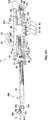
図1を参照して、遠隔外科手術システム10は、ある場所にいる外科医が、別の場所にいる患者に外科手術を行うことを可能にする。外科医は、患者と同じ手術室にいてもよく、何マイルも離れた場所にいてもよい。遠隔外科手術システム10は、装着ブラケット36により位置決め機構14に装着される力反映外科手術器具12を含む。器具12および位置決め機構14は、コンピュータ11およびマスターデバイス150によって制御される。マスターデバイス150は、遠隔地にいる外科医によって操作される。器具12および位置決め機構14は、駆動モータM1、M2、M3、M4、M5、M6およびM7(図4a、図4b、図6および図7)によって、一連のケーブルおよびプーリーとともに駆動される。 Referring to FIG. 1,
器具12は、小さい摩擦、小さい慣性、および高帯域幅を有するが、移動範囲は小さい。位置決め機構14は、移動範囲は大きいが、器具12よりも大きい慣性および低い帯域幅を有する。マクロ−マイクロ作動方式において器具12と位置決め機構14とを組み合わせることにより、その個々の構成要素のいずれよりも、高められた操作能力および力感知能力を有するシステムが得られる。位置決め機構14は、余剰な自由度を有する遠隔外科手術システム10を与え、手術作業部位にある位置決め器具12の助けとなり、器具12がほぼ、必要な手術を行うための適切な位置となる。このように、器具12を位置決め機構14に装着することにより、遠隔外科手術システム10には、器具12の使用を通して良質な力制御が与えられ、それと同時に、位置決め機構14のため、大きい移動範囲を有する。 The
器具12は、回転式ジョイント26によって遠位部28bに回転可能に連結される近位部28aを有する。近位部28aは、摺動ジョイント30を形成する摺動ブラケット96に摺動自在に連結される。摺動ブラケット96は、ブラケット36に固定される。遠位部28bは、リストジョイント16によって管状支持部材24に回転可能に連結されるリスト部材を含む。2つの対向する作業部材20aおよび20bはそれぞれ駆動されるキャプスタン18aおよび18bに固定され、駆動されるキャプスタン18aおよび18bはそれぞれキャプスタンジョイント19aおよび19bを中心に回転可能にリスト部材22に連結される。作業部材20aおよび20bは、鋏、開創器、針ドライバおよび電気メス(electrocautery)器具などの標準の外科手術器具の操作端であり得る。 The
器具12は、5の自由度を有し、摺動ジョイント30が、長手方向の軸Cに沿って線形動作を与え、回転ジョイント26が、軸C周りの回転動作を与え、リストジョイント16が、軸B周りの回転動作を与え、キャプスタンジョイント19aおよび19bが、作業部材20aおよび20bに対して、軸A周りの回転動作を与える。器具12は、マスターデバイス150に4段階(four degrees)の力反映を与えるため、外科医は、手術処置の触知(tactile)フィードバックを有し得る。これらの力反映段階は、作業部材20aおよび20bに与えられる力と、作業部材20aと20bとの間の保持力とを含む。しかし、力の反映は、任意の特定の実施形態において必要に応じてより多いまたはより少ない動作軸に与えられ得る。 The
位置決め機構14は、軸E−E周りに回転する、4つのバーを有するリンケージからなる、2の自由度を有するリンケージである。位置決め機構14は、ジョイント34、38、48、50、52、54および56によって共に結合される一連の剛性部材36、40、42、60および62を有する。位置決め機構14はまた、耳部58を有する基部68を含み、耳部58は、シャフト64および66を係合して、軸E−E周りに旋回するジョイント57を形成する。ジョイント56は、リンク62が、軸E−Eに直交する軸D−D周りに回転することを可能にする。剛性部材36、40、42、60および62の4つのバーを有するリンケージは、この回転をブラケット36を介して器具12に伝え、器具12を軸E−Eおよび軸D’−D’周りに回転させる(軸D’−D’は、軸D−Dに平行であり、軸E−Eに直交する)。このように、4つのバーを有するリンケージは、器具12の点Psを、遠隔中心111に中心を有する球体の表面の周りで移動させるように動作する。The
ここでは4つのバーを有するリンケージが示されているが、本発明は、任意の適切な位置決め機構を組み込み得る。最低侵襲性外科手術が最小である手術に適切なものとするために、位置決め機構は、外科手術器具を、器具12が患者に挿入される開口で交差する軸周りに旋回させなければならない。本発明の利点の1つは、位置決め機構が、力フィードバック情報を与える必要がないことであり、これにより、位置決め機構の広い設計範囲が可能となる。 Although a linkage with four bars is shown here, the present invention may incorporate any suitable positioning mechanism. In order to be suitable for the minimally invasive surgical procedure, the positioning mechanism must pivot the surgical instrument about an axis that intersects the opening through which the
図2を参照して、器具12および位置決め機構14を制御するのに適切な触覚マスターデバイス150の簡略化された図が示される。マスターデバイス150は、マウント156(部分的に図示)に旋回可能に連結される、2の自由度を有するリンケージ158を含む。使用中、マウント156は、マウントが一定の基準点を与えるように、コンソールまたはカートまたは同様の固定支持体に適切な位置で固定される。リンケージ158は、回転式ジョイント170、171および172を含む。作業部材制御機構152は、ジンバルジョイント164によってリンケージ158の遠位端154に連結される。マスターデバイス150はまた、一連のエンコーダ(図示せず)を含み、このエンコーダは、器具12および位置決め機構14の駆動モータを制御するために、コンピュータ11に、各ジョイントの回転位置を与える。 Referring to FIG. 2, a simplified diagram of a
使用中、外科医は、自分の親指および人差し指を、作業部材制御機構152のフィンガグリップ166に入れて、マウント156に対する機構152の位置および向きを操作する。これにより、器具12および位置決め機構14の動きを制御し、手術部位に対する器具12の遠位端の位置を制御する。 In use, the surgeon places his thumb and index finger into the
マスターデバイス150の機構152は、軸F−F、H−HおよびK−Kに沿って3つの並進自由度を有する。マスターデバイス150のジョイント170、171および172の回転は、ジンバルジョイント164の中心点である機構152上の点Pmの位置を決定する。点Pmの位置により、作業部材20aおよび20bをつなぐ弧の途中に位置する点Ps(図1、図4および図5参照)の位置が制御される。これにより、機構152を操作する際に外科医によって引き起こされる、軸F−F、H−HおよびK−Kに沿った点Pmの並進は、ジョイント170、171および172のエンコーダによって検出される。エンコーダからの情報は、コンピュータ11に与えられ、コンピュータ11は、位置決め機構14および器具のモータに対する適切な電流を制御して、器具の点Psの対応する動きを引き起こす。The
マスターデバイス150の機構152はさらに、軸F−F、H−HおよびK−K周りに3つの回転自由度を有する。機構152のリンググリップ166を、矢印176で示すように、ジンバルジョイント164に対して軸F−F周りに回転させることにより、器具12の作業部材20aおよび20bの、軸G周りの正味の回転が制御される(図1、図4および図5)。軸Gは、リスト部材22から軸Aに対して垂直な方向に且つ作業部材20aと20bとの間に延びる軸である。作業部材20aおよび20bの軸G周りの正味の回転は、器具構成要素の軸A−AおよびB−B周りの協調(coordinate)された回転を必要とする。コンピュータ11は、標準的な方法に従って、マスターの回転から器具の回転への適切な変換を決定する。同様に、機構152を、矢印178で示すように軸K−K周りに、または矢印174で示すように軸H−H周りに回転させることはさらに、器具12の軸A−A、B−BおよびC−C周りの協調運動を引き起こし、それにより器具の作業部材の対応する回転運動を引き起こす。 The
機構152は、フィンガグリップ166が矢印175によって示すようにくっついておよび離れて動き得るという点で、第7の自由度を有する。フィンガグリップ166の相対的な動きは、モータM8のエンコーダE8により検出される。位置データは、エンコーダE8からコンピュータ11へ伝送される。コンピュータE8は、その後、適切な信号を器具12のモータM1〜M4に伝送して、それに対応する、キャプスタンジョイント19aおよび19b並びに作業部材20aおよび20bの相対的な運動を引き起こす。 The
作業部材制御機構152は、図2に示すような典型的な外科器具ハンドルを含み得るが、変形例として外科医の指により操作され得るシンブルまたは同様のデバイスを含み得る。別の実施形態による作業部材制御機構152は、器具12を方向付ける(orientate)ジンバルジョイント164に連結されたシンプルなウォンドにより置換され得る。記載しているシステムにおいてマスターとして用いられるに適した装置の1つは、参考のためここに援用する、”Force Reflecting Haptic Interface”いう名称の米国特許第5,587,937号に記載されている。別の適切なマスターデバイスは、参考のためここに援用する、”ElectromechanicalHuman−Computer Interface With Force−Feedback”という名称の米国特許第5,576,727号に記載されている。本発明での使用において、上記文献に開示された装置は、作業部材を把持することからの力反映を提供するために、より大きな(powered)更なる自由度の追加を要する。潜在的に、本実施形態において、フィンガグリッパ166、モータM8およびエンコーダE8は、外科医の別の手で操作されるように別個の機構上に位置し得る。あるいは、フィンガグリッパは、外科医が操作するために、同一のデバイス上のモータおよびエンコーダに取り付けられ得る。 The working
腹腔鏡を用いる手術のために遠隔外科手術システム10を用いる場合、位置決め機構14を、手動操作セットアップジョイント(図示せず)に取り付ける。このセットアップジョイントは、患者に対して適所に安定的に取り付けられた外科用カートに取り付けられ得る。セットアップジョイントは、位置決め機構14を、手術台に取り付けられたレールに直接取り付けるためにも用いられ得る。第3の変形例において、セットアップジョイントは、手術室において床、壁、または天井に恒久的に取り付けられ得る。全てのセットアップジョイントに共通の特徴は、手術手順のためのセットアップ中に、位置決めアームの基部が患者に対して相対的に移動することを可能にし、点111が手術部位の大まかなロケーションにおいて患者の身体上の適切なエントリポイントにあるようにアームが位置づけられることを可能にするということである。好適には、セットアップジョイントは、6つの自由度を有し、従って患者に対する、位置決め機構14の並進移動および回転を可能にする。典型的には、セットアップジョイントは、リモートセンタ点111の患者に対する移動手順中に適切な位置にロックされる。 When using the
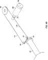
図3を参照すると、セットアップジョイントを用いて工具を位置決めして工具を適切な位置にロックした後、外科医は、マスターデバイス150を操作して患者の腹壁110の小さい切開112を介して挿入されるカニューレ113を通して器具12を移動させる。マスターデバイス150の操作に応答して、器具12の遠位部28bが、摺動ジョイント30に沿って位置決め機構14に対して下流に並進移動して、カニューレ113および腹壁110を通って挿入される。一旦腹部内に入ると、器具12の遠位部28bはさらに、所望の手術部位上に位置づけられる。図3は、大きな位置移動を行うために前方および後方位置における、軸D−D周りに旋回する機構14の動きを示す。位置決め機構14は、軸DおよびE周りに旋回して、遠隔外科手術システム10の大きな移動を行う。その間、細かい動きは、器具12のジョイントによって行われる。器具12上の点111は、位置決め機構14からの回転のリモート点であり、これはエントリ創傷112に一致する。位置決め機構14が軸Dおよび軸E周りに旋回すると、器具12は点111周りに旋回する。切開112近傍の点111は、器具12が患者内で旋回している間、静止したままであることに留意されたい。その結果、切開112は、器具12を受け入れるに十分な大きさであればよい。 Referring to FIG. 3, after positioning the tool using the setup joint and locking the tool in place, the surgeon manipulates the
位置決め機構14が旋回すると、リスト部材22または作業部材20a/20bが組織と係合してジョイント16または19a/19b周りの回転を引き起こす場合、器具12は、器具12が位置決め機構14に対して作業スペースの中央部に維持されるように、それ自体を再び方向付ける。必要であれば、位置決め機構14は、器具12が再方向づけしている間、速度を弛め得る。 As the
器具12が一旦適切な位置にくると、外科医は、さらにマスターデバイス150を操作することにより、器具12で患者に必要な手術手順を行う。器具12が受ける力は、マスターデバイス150によって外科医に戻って反映される(reflected back)。反映された力は、外科医が手術手順をよりよく「感じる」ことを可能にするために、スケールアップされ得る。その結果、外科医は、器具12が、あまり抵抗を与えないタイプの組織に係合することを感じることができる。さらに、マスターデバイス150の、器具12に対する移動は、器具12の精度および巧緻性が増加し得るように、スケールダウンされ得る。 Once the
位置決め機構14は広範囲の動きを有するように最適化されているため、器具12よりも大きい慣性、大きい摩擦、および低い分解能を有する傾向にある。さらに、カニューレ113内の摩擦力および切開112における妨げとなる力が、位置決め機構に適用され得る。しかし、出願人による好適な実施形態において、力反映のために力を検出するのは、主に器具である。そのため、位置決め機構のより大きい慣性および摩擦、ならびにそれに作用する外的な力は、力反映系から除外される。従って、器具12の先端とマスターデバイスとの間の力反映の質は、大幅に向上する。 Because the
図4A、図4Bおよび図5を参照して、器具12をより詳細に述べる。遠位部の管状支持部材24は軸Cに沿って延び、管状支持部材24の長さ方向に延びる一連のケーブルC1、C2、C3およびC4を収容している。ケーブルC1、C2、C3およびC4は、作業部材20aおよび20bの動作並びにリスト部材22の方向を制御するジョイント19a、19bおよび16の回転を制御する。リスト部材22は、2つの互いに対向する遠位の耳部21aおよび21bを含む。耳部21aおよび21bは、軸A−Aに沿って延びるキャプスタンジョイント19aおよび19bのそれぞれにおいて、駆動されるキャプスタン18aおよび18bを支持するUリンク(clevis)を形成する。リスト部材22はさらに、2つの対向する近位の耳部23aおよび23bを含む。耳部23aおよび23bは、軸B−Bに沿って耳部23aと舌部24aとの間に延びる中間アイドラプーリー70および72を、リストジョイント16において支持するUリンクを形成する。中間アイドラプーリー74および76は、耳部23bと舌部24aとの間で支持される。ケーブルC1、C2、C3およびC4は、以下に詳細に記載するように、駆動されるキャプスタン18a/18b、並びに中間アイドラプーリー70、72、74および76と係合する。 With reference to FIGS. 4A, 4B and 5, the
作業部材20aおよび20bは、それぞれの駆動されるキャプスタン18aおよび18bに取り外し可能に安定的に取り付けられる。作業部材20aおよび20bは図中グリッパとして示しているが、作業部材20aおよび20bは、はさみ、カッタ、把持具、鉗子または縫合をステッチするニードルホルダなどの他のタイプの作業部材に置換され得る。典型的には、作業部材は、ねじ、クリップまたは他の適切な固定具により、駆動されるキャプスタン18aおよび18bに安定的に取り付けられる。しかし、作業部材はまた、半田付けまたは溶接などによって、駆動されるキャプスタンに恒久的に取り付けられ得、または駆動されるキャプスタンと一体的に形成され得る。 The working
作業部材20aおよび20bは共に、1形態の外科用エンドエフェクタを含む。本発明の外科用器具において、他の外科用エンドエフェクタも用いられ得る。エンドエフェクタは単に、ハンドルが取り外された標準の外科用または内視用器具を含み、これらは、例えば、開創器、電気メス器具、マイクロ鉗子、マイクロニードルホルダ、切開はさみ、ブレード、イリガートルおよび縫合糸を含む。エンドエフェクタは典型的には、1つまたは2つの作業部材を含む。 Both working
器具12の近位部28aは、支持ロッド100並びに2つのガイドレール104および106によって互いに連結された支持ブラケット98および102を含む。ロータリジョイント26を形成するロータリベアリング91は、管状支持部材24を支持する支持ブラケット98内に収容される。摺動ブラケット96は線形ベアリングに沿って摺動可能にガイドレール104および106に取り付けられる。図1に示すように、摺動ブラケット96は、ブラケット36によって位置決め機構14に連結される。摺動ブラケット96は好適には、外科的用途のために、約8インチの移動を行う。駆動モータM1、M2、M3、M4およびM5は、摺動ブラケット96に取り付けられ、対応するケーブルC1、C2、C3、C4およびC5を駆動する。各駆動モータM1、M2、M3、M4およびM5は、コンピュータ11にそれぞれの駆動シャフトの回転位置を供給する、対応するエンコーダE1、E2、E3、E4およびE5を含む。 The
図4aおよび図4bに示すように、駆動モータM5は、ケーブルC5からなるケーブル駆動ループと係合する駆動シャフトキャプスタン93を有する。ケーブルは、後部張力プーリー83回りに掛けられている。ケーブルは、アイドラプーリー84および85、並びに、管状支持部材24の近位端を形成する駆動キャプスタン90回りに掛けられている。従って、モータM5の作動は、管状支持部材24およびそれが支持するエンドエフェクタを回転させるために用いられ得る。 As shown in FIGS. 4a and 4b, the drive motor M5 has a
図6を参照して、器具12のケーブル駆動系をより詳細に述べる。作業部材20aおよび20b、リスト部材22、および器具12の長手方向軸Cに沿った並進運動は、N+1作動方式を為して配列されているケーブルC1、C2、C3およびC4によって駆動される。N+1作動方式は、4つのケーブルを用いて3つの自由度を有するリストの作動を可能にする。4つのケーブルは、3つの自由度を駆動するために必要な張力要素の、理論的に可能な最小の数であり、従って器具が最小サイズおよび重量を有することを可能にする。異なる動きの作動に必要な力の大きさが大幅に異なる場合には、より多くのケーブルを用いる別の作動方式が望まれ得る。より多くのケーブルを用いることの不利な点は、重量、複雑さ、および最小サイズが増加することである。 With reference to FIG. 6, the cable drive system of the
図6において、ケーブルC1〜C4をより容易に示すために、ジョイント26の軸C−C周りの回転運動は省略されている。このような回転は、モータM1〜M4並びにプーリー70、72、74および76間においてケーブルC1〜C4をねじる結果となるにすぎない。しかし、ケーブルは、このねじれがケーブルの経路の長さを大幅に変更しないように、管状支持部材24内に配置されている。しかし、器具の過剰な回転を防止するように注意する必要がある。器具の過剰な回転は、ケーブルをねじれさせて互いに接触させ、ケーブル間に摩擦を引き起こす。 In FIG. 6, rotational movement about the axis CC of the joint 26 is omitted in order to more easily show the cables C1 to C4. Such rotation only results in twisting cables C1-C4 between motors M1-M4 and pulleys 70, 72, 74 and 76. However, the cable is positioned within the
図6に示すように、ケーブルC1およびC2は、連続ケーブルループ44の2つの側を形成する。ループ44のケーブルC1は、近位アイドラプーリー80、モータM1の駆動シャフト、中間アイドラプーリー70、および駆動されるキャプスタン18aと係合する。ケーブルループ44は、駆動されるキャプスタン18aからケーブルC2として戻り、中間アイドラプーリー76、モータM2の駆動シャフトおよび近位アイドラプーリー80と係合する。 As shown in FIG. 6, the cables C 1 and C 2 form two sides of the
図6に示すように、ケーブルC3およびC4は、ケーブル46の連続ループの2つの側を形成する。ケーブルループ46のケーブルC3は、近位アイドラプーリー78、モータM3の駆動シャフト、中間アイドラプーリー72、および駆動されるキャプスタン18bと係合する。ケーブルループ46は、駆動されるキャプスタン18bからケーブルC4として戻り、中間アイドラプーリー74、モータM4の駆動シャフトおよび近位アイドラプーリー78と係合する。 As shown in FIG. 6, cables C3 and C4 form two sides of a continuous loop of
図6に示すように、近位アイドラプーリー78および80は、近位アイドラプーリー78および80の中心に安定的に取り付けられたケーブルC7およびC6によって張力を与えられる。ケーブルC7およびC6は、近位アイドラプーリー82と係合する単一のケーブル45の2つの側を形成する。近位アイドラプーリー82は、シャフト82aによって支持ブラケット102に回転可能に取り付けられる。シャフト82aは好適には、リードねじなどの機構によって支持ブラケット102に移動可能に取り付けられる。リードねじは、その後、ケーブルC7およびC6を適切な張力に調節し得る。張力はまた、アイドラプーリー78および80を介してケーブルC1、C2、C3およびC4にも付与される。同様のリードねじ張力付与方式が、アイドラプーリー83の長手方向移動によって、ケーブルC5に張力を与えるために用いられ得る。これらの目的のために、アイドラプーリー82および83は、図3に示す単一のシャフト82aではなく、別々に調節可能なシャフト上に取り付けられることが必要であり得る。 As shown in FIG. 6, proximal idler pulleys 78 and 80 are tensioned by cables C7 and C6 that are stably attached to the center of proximal idler pulleys 78 and 80. Cables C 7 and C 6 form the two sides of a
駆動されるキャプスタン18aおよび18bは、ケーブルC1からC4がそれぞれの中間アイドラプーリと適切に係合することができるように、異なる直径を有し得る。ケーブルC1およびC2は、外側中間アイドラプーリ70および76と係合し、一方、ケーブルC3およびC4は、内側中間アイドラプーリ72および74と係合する。近位アイドラプーリ78および80は、プーリ80がプーリ78よりも大きく、ケーブルを直線状に保つような大きさになっている。 The driven
駆動モータM1、M2、M3およびM4は、ケーブルC1、C2、C3およびC4を駆動させることによって、軸B−B周りのリスト部材22の回転、軸C−Cに沿った器具12の長手方向の平行移動、および軸A−A周りの互いに独立した作業部材22aおよび22bの回転を制御する。駆動モータM1およびM2は、駆動モータM3およびM4によって駆動されるケーブルC3/C4に対して同時にケーブルC1/C2を駆動させ、リスト部材22を軸B−B周りに回転させる。駆動モータM1は、駆動モータM2によって駆動されるケーブルC2に対してケーブルC1を駆動し、キャプスタン18aおよびそれに取り付けられた作業部材20aを軸A−A周りに回転させる。さらに、駆動モータM3は、駆動モータM4によって駆動されるケーブルC4に対してケーブルC3を駆動させ、キャプスタン18bおよびそれに取り付けられた作業部材20bを軸A−A周りに回転させる。4つの駆動モータM1、M2、M3およびM4はすべて、ケーブルC1、C2、C3およびC4を同時に駆動させ、器具12を長軸C−Cに沿って並進させる。 Drive motors M1, M2, M3 and M4 drive the cables C1, C2, C3 and C4 to rotate the
摺動ブラケット96上の位置決め駆動モータM1、M2、M3、M4およびM5は、器具12の遠位部28bが小さな移動性質量(moving mass)を有するようにする。なぜなら、モータ自体は、器具の作動中に静止しているからである。モータは、位置決め機構14によって移動されるが、モータの重量および慣性は、力反映に影響しない。これは、上記のように、好ましい実施態様では、器具12のみが、マスターへ力を反映させるために用いられるからである。さらに、ギアの代わりにケーブルを用いると、器具12内の摩擦量およびバックラッシュ(backlash)が減少する。小さな移動性質量および低摩擦の組合せによって、器具12は、力反映をマスター装置150に高感度で与えることが可能となる。 Positioning drive motors M1, M2, M3, M4 and M5 on the sliding
上記のプーリー、ケーブルおよびモータの構成に対するいくつかの可能な変更は、当業者に明白である。ケーブルC1/C2、C3/C4、C5およびC7/C6は、同一のケーブル側に図示したが、ケーブルC1からC7は、それぞれ、駆動されるキャプスタン18aおよび18b、ならびに近位アイドラプーリー78、80および82に安定して取り付けられる個別のケーブルであってもよい。さらに、駆動モータM1、M2、M3およびM4は、ケーブルC1、C2、C3およびC4をそれぞれ駆動するように図示したが、いくつかの駆動モータは、ケーブルC7およびC6を駆動するために、ケーブルC1〜C4からケーブルC7およびC6に再配置され得る。特定の実施態様において用いられる特定の駆動方式の選択は、器具12によって用いられるべき力の制約、および作動中に移動する器具の部分の慣性および摩擦を減少させる必要性に依存する。 Some possible modifications to the pulley, cable and motor configurations described above will be apparent to those skilled in the art. Cables C1 / C2, C3 / C4, C5 and C7 / C6 are shown on the same cable side, but cables C1 to C7 are respectively driven
本発明の外科用器具はまた、駆動モータM1、M2、M3、M4およびM5を用いるものとして例示している。この駆動モータは、図3に示す位置エンコーダを有する標準的なサーボモータであり得る。しかし、液圧アクチュエータおよび圧電モータなどの他のアクチュエータが使用され得る。本発明の外科用器具においてアクチュエータとして用いられるためには、駆動機構は、可変かつ制御可能な力および位置制御を提供することができればよい。 The surgical instrument of the present invention is also illustrated as using drive motors M1, M2, M3, M4 and M5. This drive motor may be a standard servo motor having the position encoder shown in FIG. However, other actuators such as hydraulic actuators and piezoelectric motors can be used. In order to be used as an actuator in the surgical instrument of the present invention, the drive mechanism need only provide variable and controllable force and position control.
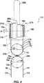
図7を参照しながら、位置決め機構14の駆動システムについて詳細に説明する。位置決め機構14は、セットアップジョイント69(図示せず)に取り付けられた基部68に取り付けられている。位置決め機構14は、駆動モータM6およびM7を有する。駆動モータM6は、位置決め機構14を軸D−D周りに約±60゜の範囲で旋回させる。駆動モータM7は、位置決め機構を軸E−E周りに約±90゜の範囲で旋回させる。各駆動モータM6およびM7は、各ドラム42および32に安定して取り付けられた各ケーブルC8およびC9を駆動する。駆動モータM6は、部材62に取り付けられ、ドラム42の周囲を移動し、部材62を軸D−D周りに回転させる。駆動モータM7は、基部68に取り付けられ、静止した状態を保ち、ドラム32の周囲を移動し、位置決め機構14を軸E−E周りに回転させる。シャフト64および66は、ドラム42から延び、耳部58に連結し、軸E−E周りの回転を可能にする。ドラム32は、シャフト66に固定されている。エンコーダE6およびE7は、各駆動モータM6およびM7の駆動シャフトの回転位置をコンピュータ11に提供する。 The drive system of the
位置決め機構14は、好ましくは、位置決め機構14および器具12の質量が、軸E−E周りにほぼ対称的に分布するように、静的に平衡にされる。例えば、駆動モータM6は、軸E−Eの下に配置され、リンク40、42、60および62の重量と部分的につりあう。力反映を損なうことなく、さらなる平衡質量(counterweight)が加えられ得る。なぜなら、これらは、位置決め機構14には慣性を加えるが、器具12には慣性を加えないからである。静的平衡は、アルミニウム管などの軽量材料をリンクの構築に用いて、位置決め機構の質量を減少させることによって、容易になされ得る。静的平衡は、平衡負荷を減少させるので有利である。静的平衡がないと、平衡負荷は駆動モータM6およびM7にかけられる。さらに、静的平衡は、駆動モータM6またはM7のいずれかが故障したときに、位置決め機構14および器具12が急速に運動しないようにさせる1つの手段である。 The
図8aおよび図8bを参照すると、ケーブルC1、C2、C3、C4、C5、C8およびC9は、それぞれの駆動モータM1、M2、M3、M4、M5、M6およびM7の駆動シャフトの周りに巻き付けていることによって駆動される。例えば、図8aにおいて、ケーブルループ46のケーブルC4は、モータM4の駆動シャフトの周りに巻き付けられている。ケーブルC4は、好ましくは、駆動シャフトの周りに2回巻き付けられ、ケーブルC4と駆動シャフトとの間に十分な摩擦を提供し、すべりを防止する。さらにすべりを防止するために、ケーブルは、はんだ、溶接または機械的固定手段によって、一点で駆動シャフトに固定され得る。しかし、このような実施態様において、ケーブルの移動範囲は、駆動シャフトまたはキャプスタンの周りに巻き付けられたケーブルの長さによって制限されるので、ケーブルは数回巻き付けられることが通常必要である。 Referring to FIGS. 8a and 8b, cables C1, C2, C3, C4, C5, C8 and C9 are wrapped around the drive shafts of the respective drive motors M1, M2, M3, M4, M5, M6 and M7. Driven by being. For example, in FIG. 8a, cable C4 of
図8bは、位置決め機構14のドラム32および42のケーブル駆動を示す。駆動モータM6のシャフトが回転すると、ケーブルC8は、シャフトの1サイドに巻き付き、他のサイドからはなれる。従って、ケーブルC8は、モータM6のシャフトを通過して並進し、結果としてドラム42は回転する。モータM6のシャフトが、ドラム42の表面に直接接触しないことに留意されたい。 FIG. 8 b shows cable drive of the
図8cは、駆動ケーブルの他の好ましい方法を示す。例えば、モータM4は、駆動ホイール43aおよびアイドラホイール43bを有し、その間で細長い部材47を摩擦駆動させる。ケーブルC4は、2つのハーフ46aおよび46bからなり、これらは、部材47の対向する端部に固定されている。 FIG. 8c shows another preferred method for the drive cable. For example, the motor M4 has a
図9は、他の好ましい器具117の遠位端およびリスト部材116を示す。器具117は、4個でなく8個の中間アイドラプーリーを有するという点で、器具12とは異なる。器具117は、リスト接合部16において中間アイドラプーリー76、74、72および70を有するが、さらに中間アイドラプーリー76a、74a、72aおよび70aを有し、これらは、シャフト118に沿ってつまみ24a上のアイドラプーリー76、74、72および70に隣接して配置されている。ケーブルC1、C2、C3およびC4は、各中間アイドラプーリーの周りに完全に巻き付きはしないが、その代わりに、各プーリーの表面と約90゜で接触するだけである。これによって、ケーブルが互いに交差し、共に摩擦するのが防止され、摩擦およびノイズが防止される。 FIG. 9 shows the distal end and wrist member 116 of another
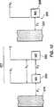
図10は、位置決め機構14および器具12のマクロ−マイクロ制御の背後にある原理を示す。マクロ−マイクロ制御は、系の力学を利用して、スレーブシステムの出力端で測定される慣性を減少させることによって力の感度を最適にする。特に、大抵の場合、遠位の自由度は、近位の自由度が有するよりも小さい移動範囲を有する。我々の場合、腹腔鏡器具の端部に取り付けられた小さなリストは、マクロ機器(位置決め機構)に取り付けられたマイクロ機器(リスト)に対応する。 FIG. 10 shows the principle behind the macro-micro control of the
ここで定義するように、マクロ−マイクロ制御とは、マクロ−マイクロシステムの遠位側(患者と相互作用する側)から測定される有効慣性を、マクロ自由度の移動範囲を保持しながら、マイクロ自由度の有効慣性付近に減少させることを目的として、適切なコントローラを介して連続して作動する2つ以上の余剰な自由度を用いることである。システムの近位側として規定されるマクロ自由度は、グラウンドに対して作動し、通常、広範囲な移動および慣性を有して大きい。マイクロ自由度は、対応する小さな範囲の移動および慣性を有して小さく、マクロ自由度に対して作動し、システムの遠位側として規定される。 As defined herein, macro-micro control refers to the effective inertia measured from the distal side of the macro-micro system (the side that interacts with the patient), while maintaining the range of movement of the macro degree of freedom. The aim is to use two or more extra degrees of freedom that operate in succession via a suitable controller, with the aim of reducing the degrees of freedom around the effective inertia. The macro degree of freedom defined as the proximal side of the system operates with respect to ground and is usually large with a wide range of movement and inertia. Micro degrees of freedom are small with corresponding small ranges of movement and inertia, operate on macro degrees of freedom and are defined as the distal side of the system.
図10は、2つの余剰アクチュエータ202および203によって動作するリニアスレーブ器具201と、1つのアクチュエータ206を有するリニアマスターデバイス205とからなる1つの自由度のマスター−スレーブシステムの一例を示す。M3は、スレーブデバイスの移動を制御するために用いられるマスターデバイス205を示す質量である。F3は、マスターアクチュエータ206によって質量M3に与えられる力である。M1は、広範囲な移動を有するマクロ機器を示す質量であり、これは、本発明の位置決め機構と等価である。F1は、マクロアクチュエータ202によってグラウンドにかけられる力である。マクロ機器は、マスター205の位置に直接スレーブされ、作業スペース内でマイクロ機器を維持するように動作する。広範囲な移動を可能にするために、マクロ機器は、大きな構造を有し、通常、比較的大きい慣性、および恐らくは大きい摩擦を有する。しかし、マクロ機器は、良好(高帯域幅)位置および速度制御を維持することが可能でなければならない。 FIG. 10 shows an example of a one-degree-of-freedom master-slave system consisting of a
M2は、マクロ機器およびマスター205に対して、比較的小さい範囲の移動を有するマイクロ機器を示す質量である。しかし、マイクロ機器M2は、小さな構造であるため、マクロ機器と比較して小さい慣性および小さい摩擦を有するように構築することが可能である。スレーブ自由度は共に、出力Xに寄与する。なぜなら、マイクロ機器は、連続してマクロ機器上に設けられるためである。マイクロ機器の力F2は、M1とM2との間に与えられる。X1は、マクロ機器の位置であり、F1は、マクロアクチュエータ202によってマクロ機器とグラウンド204との間に与えられるモータ力である。X2は、マクロ機器に対するマイクロ機器の位置である。Xは、X1とX2との組合せた結果のグラウンドに対するマイクロ機器の位置である。X3は、マスター器具M3の位置である。マスターM3を保持するユーザは、力反映として得られる力を感じる。 M2 is a mass indicating a micro device having a relatively small range of movement relative to the macro device and the master 205. However, since the micro device M2 has a small structure, it can be constructed so as to have a small inertia and a small friction compared to the macro device. Both slave degrees of freedom contribute to the output X. This is because the micro equipment is continuously provided on the macro equipment. Micro device force F2 is applied between M1 and M2. X1 is the position of the macro device, and F1 is the motor force applied between the macro device and the
この代表的なマクロ−マイクロシステムを制御する式を以下に示す。これらの式において、添え字dは、特定の位置または速度の所望値を示す。以下の式において、kp1、kp2およびkp3は、位置利得であり、kv1、kv2およびkv3は速度利得である。VはdX/dt、すなわちマクロ−マイクロ機器の速度である。V1は、dX1/dt、すなわちマクロ機器の速度である。ポスケール(posscale)は、マスターとスレーブとの間のスケーリング動作(scale motion)に用いられる尺度ファクタである。例えば、ポスケールが1と等しいとき、マスターが1cm移動すると、スレーブは1cm移動する。ポスケールが2と等しいとき、マスターが1cm移動すると、スレーブは1/2cm移動する。The formula for controlling this typical macro-micro system is shown below. In these equations, the subscript d indicates the desired value for a particular position or velocity. In the following equations, kp1 , kp2 and kp3 are position gains, and kv1 , kv2 and kv3 are velocity gains. V is dX / dt, ie the speed of the macro-micro instrument. V1 is dX1 / dt, that is, the speed of the macro device. Poscale is a scale factor used for scale motion between master and slave. For example, when the scale is equal to 1, if the master moves 1 cm, the slave moves 1 cm. When the scale is equal to 2, if the master moves 1 cm, the slave moves 1/2 cm.
Xd=X3/ポスケール 式1
Vd=V3/ポスケール 式2
X1d=Xd 式3
X2d=Xd−X1 式4
X3d=X・ポスケール 式5
V1d=Vd 式6
V2d=Vd−V1 式7
V3d=V・ポスケール 式8
F1=−kp1(X1−X1d)−kv1(V1−V1d) 式9
F2=−kp2(X2−X2d)−kv2(V2−V2d) 式10
F3=−kp3(X3−X3d)−kv3(V3−V3d) 式11
上記の式は、マクロ−マイクロ制御の1つの特定の実施を示す。実施の改変は、システムの安定性を向上させる目的で必要であり得る。しかし、上記の式から決定され得るように、位置および速度利得は両方とも、システムインピーダンスおよび安定性に影響する。マスターとスレーブとの間の力およびインピーダンススケーリングは、位置利得kp1、kp2およびkp3およびファクタポスケールを変更することによって成し遂げられる。特に、比kp3/kp2は、マスターとスレーブとの間の力利得を決定する。例えば、比kp3/kp2=2のとき、スレーブに与えられる力は、マスターで2倍に拡大される。さらに、ポスケール=1の場合、スレーブにおける物体の剛性(stiffness)もまたマスターで2倍になる。kp3/kp2=2およびポスケール=2の場合、スレーブの剛性は、マスターでは変化しないが、力は2倍になる。速度利得kv1、kv2およびkv3は、システムの安定性を制御するために用いられ得る。
Xd = X3 / Poscale Equation 1
Vd = V3 / Poscal Equation 2
X1d = Xd Formula 3
X2d = Xd -X1 Formula 4
X3d = X · Poscale Equation 5
V1d = Vd Formula 6
V2d = Vd −V1 Formula 7
V3d = V · Poscale Equation 8
F1 = −kp1 (X1 −X1d ) −kv1 (V1 −V1d ) Equation 9
F2 = −kp2 (X2 −X2d ) −kv2 (V2 −V2d )
F3 = −kp3 (X3 −X3d ) −kv3 (V3 −V3d ) Equation 11
The above equation shows one particular implementation of macro-micro control. Implementation modifications may be necessary for the purpose of improving system stability. However, as can be determined from the above equations, both position and velocity gains affect system impedance and stability. Force and impedance scaling between the master and slave is accomplished by changing the position gains kp1 , kp2 and kp3 and the factor scale. In particular, the ratio kp3 / kp2 determines the force gain between the master and the slave. For example, when the ratio kp3 / kp2 = 2, the force applied to the slave is doubled by the master. Furthermore, if the Poscale = 1, the stiffness of the object at the slave is also doubled at the master. If kp3 / kp2 = 2 and Poscale = 2, the slave stiffness does not change at the master, but the force is doubled. The speed gains kv1 , kv2 and kv3 can be used to control the stability of the system.
マクロ−マイクロ制御の質的効果を理解するためには、小さい力がM2に加えられた場合を想定するとよい。M2が小さい慣性および恐らく小さい摩擦を有しているため、M1に比較して小さい抵抗で屈曲する。この移動はマスターM3で追跡される。ユーザがM3を持っていれば、ユーザは力を感じとるであろう。M2に加わる力をユーザが感じる感度は、M2のM1に対する慣性および摩擦が減少するにつれて増加する。M2をM1に結合することの有用性は、M1がスレーブの移動の範囲を増加させることである。M2はM1に比較して短い距離のみを移動するためM1はM1の運動ベース(moving base)を提供し、結果として組み合わされたシステムは、M2の感度とM1の大きな移動範囲の両方を有している。 In order to understand the qualitative effects of macro-micro control, it may be assumed that a small force is applied to M2. Since M2 has a small inertia and possibly a small friction, it bends with a small resistance compared to M1. This movement is tracked by the master M3. If the user has M3, the user will feel power. The sensitivity with which the user feels the force applied to M2 increases as the inertia and friction of M2 with respect to M1 decreases. The usefulness of coupling M2 to M1 is that M1 increases the range of slave movement. Since M2 moves only a short distance compared to M1, M1 provides M1's moving base, and the resulting combined system has both M2 sensitivity and M1's large range of movement. ing.
図10に示すマクロ−マイクロ作動方式は、単純な1の自由度のリニアシステムである。しかし、同じ方式および同じ一般式を、周知のロボット工学および数学原理を用いて、本出願人のシステムのような3自由度システムに容易に拡張することができる。器具14の点Psの移動は3つの可能な自由度のみを有し、6の自由度を有する器具および位置決め機構の組み合わせの移動によって冗長に制御される。点Psの移動の各軸について、その軸に沿う点の移動を制御する複数のアクチュエータが存在する。マクロ−マイクロ制御下にあるそれらの各軸について、少なくとも1つのマイクロアクチュエータおよびマイクロアクチュエータと異なる少なくとも1つのマクロアクチュエータが存在する。The macro-micro actuation scheme shown in FIG. 10 is a simple linear system with one degree of freedom. However, the same scheme and the same general formula can be easily extended to a three degree of freedom system, such as Applicants' system, using well-known robotics and mathematical principles. The movement of the point Ps of the
本発明をその好適な実施態様について特に示し説明してきたが、付属の請求項で規定される発明の趣旨および範囲から逸脱することなく、形態および詳細について様々な変更をなし得ることが当業者には理解されるであろう。本発明を腹腔鏡手術について説明したが、他の形態の内視鏡手術ならびに開腹手術もまた行い得る。本器具はまた、高品質の力フィードバックで巧緻性の高い器具を必要とする適切な遠隔操作アプリケーションにも用いることができる。アプリケーションの可能性としては、爆弾処理、危険物あるいは放射性物質の取り扱い、深海アプリケーション、宇宙空間アプリケーション、またはその他の近寄れない場所におけるアプリケーションを含む。 While the invention has been particularly shown and described with respect to preferred embodiments thereof, those skilled in the art will recognize that changes may be made in form and detail without departing from the spirit and scope of the invention as defined in the appended claims. Will be understood. Although the present invention has been described for laparoscopic surgery, other forms of endoscopic surgery as well as open surgery can also be performed. The instrument can also be used in suitable remote control applications that require sophisticated instruments with high quality force feedback. Potential applications include bomb disposal, hazardous or radioactive material handling, deep sea applications, space applications, or other inaccessible applications.
本発明の上記およびその他の目的、特徴ならびに利点は、図面の好適な実施形態の以下のより具体的な説明から明らかになるであろう。図面を通して、同じ参照符号は、同じ部分を示す。図面は、必ずしも一定の縮尺で示されている訳ではなく、本発明の原理を説明する場所には強調を加えている。 The above and other objects, features and advantages of the present invention will become apparent from the following more specific description of preferred embodiments of the drawings. Like reference numerals refer to like parts throughout the drawings. The drawings are not necessarily drawn to scale, emphasis is placed where the principles of the invention are described.
Claims (12)
Translated fromJapanese患者に対して固定されるための基部;
該基部に装着され、支持部材を備える位置決め機構であって、該支持部材は、該基部に対して複数の自由度で作動する、位置決め機構;
該支持部材に着脱可能に結合された細長部材にエンドエフェクタを結合させるリスト機構を備える外科手術器具であって、該エンドエフェクタは、該支持部材に対して複数の自由度で作動し、かつ、該外科手術器具が該患者に挿入されて該エンドエフェクタを外科的作業部位に隣接した位置に置くように適合されている、外科手術器具;ならびに
該位置決め機構および該外科手術器具に結合されたマスターデバイスであって、該マスターデバイスは、該位置決め機構および該エンドエフェクタの動きを制御し、かつ、該マスターデバイスは、力フィードバック情報を該外科手術器具から複数の自由度で受け取り、該マスターデバイスが、力フィードバック情報を前記位置決め機構から受け取らない、マスターデバイス、を備える、外科手術システム。A surgical system,
A base to be secured to the patient;
A positioning mechanism mounted on the base and comprising a support member, the support member operating in a plurality of degrees of freedom relative to the base;
A surgical instrument comprising a wrist mechanism for coupling an end effector to an elongate member removably coupled to the support member, the end effector operating in a plurality of degrees of freedom relative to the support member; and A surgical instrument adapted to be inserted into the patient to place the end effector in a position adjacent to a surgical work site; and a master device coupled to the positioning mechanism and the surgical instrument. a is, the master device controls the movement of the positioning mechanism and the end effector, and the master devicewill receive the force feedback information from the surgical instrument in a plurality of degrees of freedom,the master device, force feedback A surgical systemcomprising a master devicethatdoes not receive information from the positioning mechanism. Stem.
Applications Claiming Priority (2)
| Application Number | Priority Date | Filing Date | Title |
|---|---|---|---|
| US1798196P | 1996-05-20 | 1996-05-20 | |
| US08/858,048US5807377A (en) | 1996-05-20 | 1997-05-16 | Force-reflecting surgical instrument and positioning mechanism for performing minimally invasive surgery with enhanced dexterity and sensitivity |
Related Parent Applications (1)
| Application Number | Title | Priority Date | Filing Date |
|---|---|---|---|
| JP54267197ADivisionJP4077516B2 (en) | 1996-05-20 | 1997-05-20 | Force reflecting surgical instruments and positioning mechanisms for performing minimally invasive surgery with improved sophistication and sensitivity |
Publications (2)
| Publication Number | Publication Date |
|---|---|
| JP2007050270A JP2007050270A (en) | 2007-03-01 |
| JP4443548B2true JP4443548B2 (en) | 2010-03-31 |
Family
ID=26690587
Family Applications (9)
| Application Number | Title | Priority Date | Filing Date |
|---|---|---|---|
| JP54267197AExpired - LifetimeJP4077516B2 (en) | 1996-05-20 | 1997-05-20 | Force reflecting surgical instruments and positioning mechanisms for performing minimally invasive surgery with improved sophistication and sensitivity |
| JP2006273077AExpired - LifetimeJP4443548B2 (en) | 1996-05-20 | 2006-10-04 | Force reflecting surgical instruments and positioning mechanisms for performing minimally invasive surgery with improved sophistication and sensitivity |
| JP2007161960AWithdrawnJP2007289726A (en) | 1996-05-20 | 2007-06-19 | Force reflective surgical operating tool and positioning mechanism for performing minimum invasive surgical operation with improved elaborateness and sensitivity |
| JP2010224177AExpired - LifetimeJP5207558B2 (en) | 1996-05-20 | 2010-10-01 | Force reflecting surgical instruments and positioning mechanisms for performing minimally invasive surgery with improved sophistication and sensitivity |
| JP2012060838AWithdrawnJP2012179363A (en) | 1996-05-20 | 2012-03-16 | Force-reflecting surgical instrument and positioning mechanism for performing minimally invasive surgery with enhanced dexterity and sensitivity |
| JP2012060837AExpired - LifetimeJP5868746B2 (en) | 1996-05-20 | 2012-03-16 | Force reflecting surgical instruments and positioning mechanisms for performing minimally invasive surgery with improved sophistication and sensitivity |
| JP2014102072AWithdrawnJP2014236969A (en) | 1996-05-20 | 2014-05-16 | Force-reflecting surgical instrument and positioning mechanism for performing minimally invasive surgery with enhanced dexterity and sensitivity |
| JP2015002796AWithdrawnJP2015107340A (en) | 1996-05-20 | 2015-01-09 | Force-reflecting surgical instrument and positioning mechanism for performing minimally invasive surgery with enhanced dexterity and sensitivity |
| JP2016112427AWithdrawnJP2016185335A (en) | 1996-05-20 | 2016-06-06 | Force-reflecting surgical instrument and positioning mechanism for performing minimally invasive surgery with enhanced dexterity and sensitivity |
Family Applications Before (1)
| Application Number | Title | Priority Date | Filing Date |
|---|---|---|---|
| JP54267197AExpired - LifetimeJP4077516B2 (en) | 1996-05-20 | 1997-05-20 | Force reflecting surgical instruments and positioning mechanisms for performing minimally invasive surgery with improved sophistication and sensitivity |
Family Applications After (7)
| Application Number | Title | Priority Date | Filing Date |
|---|---|---|---|
| JP2007161960AWithdrawnJP2007289726A (en) | 1996-05-20 | 2007-06-19 | Force reflective surgical operating tool and positioning mechanism for performing minimum invasive surgical operation with improved elaborateness and sensitivity |
| JP2010224177AExpired - LifetimeJP5207558B2 (en) | 1996-05-20 | 2010-10-01 | Force reflecting surgical instruments and positioning mechanisms for performing minimally invasive surgery with improved sophistication and sensitivity |
| JP2012060838AWithdrawnJP2012179363A (en) | 1996-05-20 | 2012-03-16 | Force-reflecting surgical instrument and positioning mechanism for performing minimally invasive surgery with enhanced dexterity and sensitivity |
| JP2012060837AExpired - LifetimeJP5868746B2 (en) | 1996-05-20 | 2012-03-16 | Force reflecting surgical instruments and positioning mechanisms for performing minimally invasive surgery with improved sophistication and sensitivity |
| JP2014102072AWithdrawnJP2014236969A (en) | 1996-05-20 | 2014-05-16 | Force-reflecting surgical instrument and positioning mechanism for performing minimally invasive surgery with enhanced dexterity and sensitivity |
| JP2015002796AWithdrawnJP2015107340A (en) | 1996-05-20 | 2015-01-09 | Force-reflecting surgical instrument and positioning mechanism for performing minimally invasive surgery with enhanced dexterity and sensitivity |
| JP2016112427AWithdrawnJP2016185335A (en) | 1996-05-20 | 2016-06-06 | Force-reflecting surgical instrument and positioning mechanism for performing minimally invasive surgery with enhanced dexterity and sensitivity |
Country Status (4)
| Country | Link |
|---|---|
| US (1) | US5807377A (en) |
| JP (9) | JP4077516B2 (en) |
| CA (1) | CA2255692C (en) |
| WO (1) | WO1997043943A1 (en) |
Cited By (1)
| Publication number | Priority date | Publication date | Assignee | Title |
|---|---|---|---|---|
| KR101242581B1 (en) | 2011-05-20 | 2013-03-25 | 인하대학교 산학협력단 | 3-degrees of freedom active haptic master system using ER fluid |
Families Citing this family (313)
| Publication number | Priority date | Publication date | Assignee | Title |
|---|---|---|---|---|
| US5762458A (en) | 1996-02-20 | 1998-06-09 | Computer Motion, Inc. | Method and apparatus for performing minimally invasive cardiac procedures |
| US5625576A (en) | 1993-10-01 | 1997-04-29 | Massachusetts Institute Of Technology | Force reflecting haptic interface |
| US6646541B1 (en) | 1996-06-24 | 2003-11-11 | Computer Motion, Inc. | General purpose distributed operating room control system |
| US7053752B2 (en) | 1996-08-06 | 2006-05-30 | Intuitive Surgical | General purpose distributed operating room control system |
| US6463361B1 (en) | 1994-09-22 | 2002-10-08 | Computer Motion, Inc. | Speech interface for an automated endoscopic system |
| US6436107B1 (en) | 1996-02-20 | 2002-08-20 | Computer Motion, Inc. | Method and apparatus for performing minimally invasive surgical procedures |
| US5855583A (en)* | 1996-02-20 | 1999-01-05 | Computer Motion, Inc. | Method and apparatus for performing minimally invasive cardiac procedures |
| US5971976A (en)* | 1996-02-20 | 1999-10-26 | Computer Motion, Inc. | Motion minimization and compensation system for use in surgical procedures |
| US5807377A (en)* | 1996-05-20 | 1998-09-15 | Intuitive Surgical, Inc. | Force-reflecting surgical instrument and positioning mechanism for performing minimally invasive surgery with enhanced dexterity and sensitivity |
| US5792135A (en) | 1996-05-20 | 1998-08-11 | Intuitive Surgical, Inc. | Articulated surgical instrument for performing minimally invasive surgery with enhanced dexterity and sensitivity |
| US6911916B1 (en) | 1996-06-24 | 2005-06-28 | The Cleveland Clinic Foundation | Method and apparatus for accessing medical data over a network |
| US6496099B2 (en) | 1996-06-24 | 2002-12-17 | Computer Motion, Inc. | General purpose distributed operating room control system |
| US6364888B1 (en) | 1996-09-09 | 2002-04-02 | Intuitive Surgical, Inc. | Alignment of master and slave in a minimally invasive surgical apparatus |
| US6132441A (en) | 1996-11-22 | 2000-10-17 | Computer Motion, Inc. | Rigidly-linked articulating wrist with decoupled motion transmission |
| US9050119B2 (en) | 2005-12-20 | 2015-06-09 | Intuitive Surgical Operations, Inc. | Cable tensioning in a robotic surgical system |
| US7727244B2 (en) | 1997-11-21 | 2010-06-01 | Intuitive Surgical Operation, Inc. | Sterile surgical drape |
| US7666191B2 (en) | 1996-12-12 | 2010-02-23 | Intuitive Surgical, Inc. | Robotic surgical system with sterile surgical adaptor |
| US8182469B2 (en) | 1997-11-21 | 2012-05-22 | Intuitive Surgical Operations, Inc. | Surgical accessory clamp and method |
| US6132368A (en)* | 1996-12-12 | 2000-10-17 | Intuitive Surgical, Inc. | Multi-component telepresence system and method |
| US8529582B2 (en) | 1996-12-12 | 2013-09-10 | Intuitive Surgical Operations, Inc. | Instrument interface of a robotic surgical system |
| US8206406B2 (en) | 1996-12-12 | 2012-06-26 | Intuitive Surgical Operations, Inc. | Disposable sterile surgical adaptor |
| US6331181B1 (en) | 1998-12-08 | 2001-12-18 | Intuitive Surgical, Inc. | Surgical robotic tools, data architecture, and use |
| US6231565B1 (en) | 1997-06-18 | 2001-05-15 | United States Surgical Corporation | Robotic arm DLUs for performing surgical tasks |
| US6711436B1 (en) | 1997-08-08 | 2004-03-23 | Duke University | Compositions, apparatus and methods for facilitating surgical procedures |
| US6231585B1 (en) | 1997-11-20 | 2001-05-15 | Medivas, Llc | Device for stabilizing a treatment site and method of use |
| US6035228A (en)* | 1997-11-28 | 2000-03-07 | Picker International, Inc. | Frameless stereotactic arm apparatus and method of using same |
| US6247738B1 (en) | 1998-01-20 | 2001-06-19 | Daum Gmbh | Robot hand |
| US6860878B2 (en)* | 1998-02-24 | 2005-03-01 | Endovia Medical Inc. | Interchangeable instrument |
| US7713190B2 (en) | 1998-02-24 | 2010-05-11 | Hansen Medical, Inc. | Flexible instrument |
| US6810281B2 (en) | 2000-12-21 | 2004-10-26 | Endovia Medical, Inc. | Medical mapping system |
| US7789875B2 (en) | 1998-02-24 | 2010-09-07 | Hansen Medical, Inc. | Surgical instruments |
| US7297142B2 (en)* | 1998-02-24 | 2007-11-20 | Hansen Medical, Inc. | Interchangeable surgical instrument |
| US6949106B2 (en) | 1998-02-24 | 2005-09-27 | Endovia Medical, Inc. | Surgical instrument |
| US8303576B2 (en) | 1998-02-24 | 2012-11-06 | Hansen Medical, Inc. | Interchangeable surgical instrument |
| US20020095175A1 (en)* | 1998-02-24 | 2002-07-18 | Brock David L. | Flexible instrument |
| US7090683B2 (en)* | 1998-02-24 | 2006-08-15 | Hansen Medical, Inc. | Flexible instrument |
| US7775972B2 (en) | 1998-02-24 | 2010-08-17 | Hansen Medical, Inc. | Flexible instrument |
| US20020128661A1 (en)* | 1998-02-24 | 2002-09-12 | Brock David L. | Surgical instrument |
| US8414598B2 (en) | 1998-02-24 | 2013-04-09 | Hansen Medical, Inc. | Flexible instrument |
| US7901399B2 (en) | 1998-02-24 | 2011-03-08 | Hansen Medical, Inc. | Interchangeable surgical instrument |
| US6692485B1 (en) | 1998-02-24 | 2004-02-17 | Endovia Medical, Inc. | Articulated apparatus for telemanipulator system |
| US7758569B2 (en) | 1998-02-24 | 2010-07-20 | Hansen Medical, Inc. | Interchangeable surgical instrument |
| ES2277430T3 (en)* | 1998-03-04 | 2007-07-01 | Visx Incorporated | LASER PRESBORAGE TREATMENT SYSTEM. |
| US6096004A (en)* | 1998-07-10 | 2000-08-01 | Mitsubishi Electric Information Technology Center America, Inc. (Ita) | Master/slave system for the manipulation of tubular medical tools |
| US6985133B1 (en) | 1998-07-17 | 2006-01-10 | Sensable Technologies, Inc. | Force reflecting haptic interface |
| US6461320B1 (en) | 1998-08-12 | 2002-10-08 | Cardica, Inc. | Method and system for attaching a graft to a blood vessel |
| US6206913B1 (en) | 1998-08-12 | 2001-03-27 | Vascular Innovations, Inc. | Method and system for attaching a graft to a blood vessel |
| US6951535B2 (en) | 2002-01-16 | 2005-10-04 | Intuitive Surgical, Inc. | Tele-medicine system that transmits an entire state of a subsystem |
| US6852107B2 (en) | 2002-01-16 | 2005-02-08 | Computer Motion, Inc. | Minimally invasive surgical training using robotics and tele-collaboration |
| US6398726B1 (en) | 1998-11-20 | 2002-06-04 | Intuitive Surgical, Inc. | Stabilizer for robotic beating-heart surgery |
| US8527094B2 (en) | 1998-11-20 | 2013-09-03 | Intuitive Surgical Operations, Inc. | Multi-user medical robotic system for collaboration or training in minimally invasive surgical procedures |
| US6659939B2 (en) | 1998-11-20 | 2003-12-09 | Intuitive Surgical, Inc. | Cooperative minimally invasive telesurgical system |
| US6493608B1 (en) | 1999-04-07 | 2002-12-10 | Intuitive Surgical, Inc. | Aspects of a control system of a minimally invasive surgical apparatus |
| US6538634B1 (en) | 1998-12-18 | 2003-03-25 | Kent Ridge Digital Labs | Apparatus for the simulation of image-guided surgery |
| US6286387B1 (en)* | 1999-03-03 | 2001-09-11 | Suzuki Motor Corporation | Three-dimensional input manipulator |
| US6594552B1 (en)* | 1999-04-07 | 2003-07-15 | Intuitive Surgical, Inc. | Grip strength with tactile feedback for robotic surgery |
| US6565554B1 (en) | 1999-04-07 | 2003-05-20 | Intuitive Surgical, Inc. | Friction compensation in a minimally invasive surgical apparatus |
| US6424885B1 (en) | 1999-04-07 | 2002-07-23 | Intuitive Surgical, Inc. | Camera referenced control in a minimally invasive surgical apparatus |
| US8944070B2 (en) | 1999-04-07 | 2015-02-03 | Intuitive Surgical Operations, Inc. | Non-force reflecting method for providing tool force information to a user of a telesurgical system |
| US10820949B2 (en)* | 1999-04-07 | 2020-11-03 | Intuitive Surgical Operations, Inc. | Medical robotic system with dynamically adjustable slave manipulator characteristics |
| EP1224918A3 (en)* | 1999-05-10 | 2002-12-18 | endoVia Medical Inc. | Surgical instrument |
| US6428550B1 (en) | 1999-05-18 | 2002-08-06 | Cardica, Inc. | Sutureless closure and deployment system for connecting blood vessels |
| US6673088B1 (en) | 1999-05-18 | 2004-01-06 | Cardica, Inc. | Tissue punch |
| AU5143000A (en) | 1999-05-18 | 2000-12-05 | Vascular Innovations, Inc. | Implantable medical device such as an anastomosis device |
| US6719769B2 (en) | 1999-11-15 | 2004-04-13 | Cardica, Inc. | Integrated anastomosis tool with graft vessel attachment device and cutting device |
| AU5150600A (en) | 1999-05-18 | 2000-12-05 | Vascular Innovations, Inc. | Tissue punch |
| US7048751B2 (en) | 2001-12-06 | 2006-05-23 | Cardica, Inc. | Implantable medical device such as an anastomosis device |
| US6981941B2 (en) | 1999-06-02 | 2006-01-03 | Power Medical Interventions | Electro-mechanical surgical device |
| US6315184B1 (en) | 1999-06-02 | 2001-11-13 | Powermed, Inc. | Stapling device for use with an electromechanical driver device for use with anastomosing, stapling, and resecting instruments |
| US6793652B1 (en) | 1999-06-02 | 2004-09-21 | Power Medical Interventions, Inc. | Electro-mechanical surgical device |
| US8025199B2 (en) | 2004-02-23 | 2011-09-27 | Tyco Healthcare Group Lp | Surgical cutting and stapling device |
| US7032798B2 (en) | 1999-06-02 | 2006-04-25 | Power Medical Interventions, Inc. | Electro-mechanical surgical device |
| US7951071B2 (en) | 1999-06-02 | 2011-05-31 | Tyco Healthcare Group Lp | Moisture-detecting shaft for use with an electro-mechanical surgical device |
| US7695485B2 (en) | 2001-11-30 | 2010-04-13 | Power Medical Interventions, Llc | Surgical device |
| US6610071B1 (en)* | 1999-07-26 | 2003-08-26 | Beth Israel Deaconess Medical Center | Suture system |
| US7217240B2 (en) | 1999-10-01 | 2007-05-15 | Intuitive Surgical, Inc. | Heart stabilizer |
| US6592572B1 (en) | 1999-11-22 | 2003-07-15 | Olympus Optical Co., Ltd. | Surgical operation apparatus |
| US7635390B1 (en)* | 2000-01-14 | 2009-12-22 | Marctec, Llc | Joint replacement component having a modular articulating surface |
| US6377011B1 (en) | 2000-01-26 | 2002-04-23 | Massachusetts Institute Of Technology | Force feedback user interface for minimally invasive surgical simulator and teleoperator and other similar apparatus |
| US8016855B2 (en) | 2002-01-08 | 2011-09-13 | Tyco Healthcare Group Lp | Surgical device |
| EP2005914B1 (en) | 2000-07-20 | 2012-04-04 | CareFusion 2200, Inc. | Hand-actuated articulating surgical tool |
| US20100241137A1 (en)* | 2000-07-20 | 2010-09-23 | Mark Doyle | Hand-actuated articulating surgical tool |
| US6726699B1 (en) | 2000-08-15 | 2004-04-27 | Computer Motion, Inc. | Instrument guide |
| US6776785B1 (en) | 2000-10-12 | 2004-08-17 | Cardica, Inc. | Implantable superelastic anastomosis device |
| US6471713B1 (en) | 2000-11-13 | 2002-10-29 | Cardica, Inc. | System for deploying an anastomosis device and method of performing anastomosis |
| WO2002043569A2 (en) | 2000-11-28 | 2002-06-06 | Intuitive Surgical, Inc. | Endoscopic beating-heart stabilizer and vessel occlusion fastener |
| US7105005B2 (en)* | 2001-01-29 | 2006-09-12 | Scanlan International, Inc. | Arteriotomy scissors for minimally invasive surgical procedures |
| US20090182226A1 (en)* | 2001-02-15 | 2009-07-16 | Barry Weitzner | Catheter tracking system |
| US7766894B2 (en) | 2001-02-15 | 2010-08-03 | Hansen Medical, Inc. | Coaxial catheter system |
| US8414505B1 (en) | 2001-02-15 | 2013-04-09 | Hansen Medical, Inc. | Catheter driver system |
| US20030135204A1 (en) | 2001-02-15 | 2003-07-17 | Endo Via Medical, Inc. | Robotically controlled medical instrument with a flexible section |
| US7699835B2 (en) | 2001-02-15 | 2010-04-20 | Hansen Medical, Inc. | Robotically controlled surgical instruments |
| US20020165524A1 (en)* | 2001-05-01 | 2002-11-07 | Dan Sanchez | Pivot point arm for a robotic system used to perform a surgical procedure |
| IL143255A (en) | 2001-05-20 | 2015-09-24 | Simbionix Ltd | Endoscopic ultrasonography simulation |
| US7708741B1 (en) | 2001-08-28 | 2010-05-04 | Marctec, Llc | Method of preparing bones for knee replacement surgery |
| US6728599B2 (en) | 2001-09-07 | 2004-04-27 | Computer Motion, Inc. | Modularity system for computer assisted surgery |
| US6587750B2 (en) | 2001-09-25 | 2003-07-01 | Intuitive Surgical, Inc. | Removable infinite roll master grip handle and touch sensor for robotic surgery |
| US6839612B2 (en) | 2001-12-07 | 2005-01-04 | Institute Surgical, Inc. | Microwrist system for surgical procedures |
| US6793653B2 (en) | 2001-12-08 | 2004-09-21 | Computer Motion, Inc. | Multifunctional handle for a medical robotic system |
| US6723087B2 (en)* | 2001-12-14 | 2004-04-20 | Medtronic, Inc. | Apparatus and method for performing surgery on a patient |
| US9113878B2 (en) | 2002-01-08 | 2015-08-25 | Covidien Lp | Pinion clip for right angle linear cutter |
| US7335216B2 (en) | 2002-01-22 | 2008-02-26 | Cardica, Inc. | Tool for creating an opening in tissue |
| US7029482B1 (en) | 2002-01-22 | 2006-04-18 | Cardica, Inc. | Integrated anastomosis system |
| US8012164B1 (en) | 2002-01-22 | 2011-09-06 | Cardica, Inc. | Method and apparatus for creating an opening in the wall of a tubular vessel |
| US7223274B2 (en) | 2002-01-23 | 2007-05-29 | Cardica, Inc. | Method of performing anastomosis |
| AU2003214837B2 (en)* | 2002-02-06 | 2008-06-12 | The Johns Hopkins University | Remote center of motion robotic system and method |
| US7428855B2 (en)* | 2002-05-22 | 2008-09-30 | Duval Eugene F | Counter balance system and method with one or more mechanical arms |
| CA2489727C (en) | 2002-06-14 | 2011-04-26 | Power Medical Interventions, Inc. | Surgical device |
| AU2003257309A1 (en) | 2002-08-13 | 2004-02-25 | Microbotics Corporation | Microsurgical robot system |
| US20040176751A1 (en) | 2002-08-14 | 2004-09-09 | Endovia Medical, Inc. | Robotic medical instrument system |
| US7331967B2 (en)* | 2002-09-09 | 2008-02-19 | Hansen Medical, Inc. | Surgical instrument coupling mechanism |
| US6932808B2 (en)* | 2002-11-19 | 2005-08-23 | Visx, Incorporated | Ablation shape for the correction of presbyopia |
| SE0203567D0 (en)* | 2002-12-03 | 2002-12-03 | Mentice Ab | In interventional simulator control system |
| US8911086B2 (en) | 2002-12-06 | 2014-12-16 | Amo Manufacturing Usa, Llc | Compound modulation transfer function for laser surgery and other optical applications |
| US7320517B2 (en) | 2002-12-06 | 2008-01-22 | Visx, Incorporated | Compound modulation transfer function for laser surgery and other optical applications |
| US7460288B2 (en)* | 2002-12-06 | 2008-12-02 | Amo Manufacturing Usa, Llc | Methods for determining refractive corrections from wavefront measurements |
| MXPA05006000A (en)* | 2002-12-06 | 2005-08-18 | Visx Inc | Presbyopia correction using patient data. |
| US8342686B2 (en) | 2002-12-06 | 2013-01-01 | Amo Manufacturing Usa, Llc. | Compound modulation transfer function for laser surgery and other optical applications |
| US7386365B2 (en) | 2004-05-04 | 2008-06-10 | Intuitive Surgical, Inc. | Tool grip calibration for robotic surgery |
| US7434936B2 (en)* | 2002-12-06 | 2008-10-14 | Amo Manufacturing Usa, Llc | Residual accommodation threshold for correction of presbyopia and other presbyopia correction using patient data |
| US8007511B2 (en)* | 2003-06-06 | 2011-08-30 | Hansen Medical, Inc. | Surgical instrument design |
| US7042184B2 (en) | 2003-07-08 | 2006-05-09 | Board Of Regents Of The University Of Nebraska | Microrobot for surgical applications |
| US7960935B2 (en) | 2003-07-08 | 2011-06-14 | The Board Of Regents Of The University Of Nebraska | Robotic devices with agent delivery components and related methods |
| US7850456B2 (en) | 2003-07-15 | 2010-12-14 | Simbionix Ltd. | Surgical simulation device, system and method |
| US7676194B2 (en)* | 2003-08-22 | 2010-03-09 | Rappaport Theodore S | Broadband repeater with security for ultrawideband technologies |
| WO2005039835A1 (en)* | 2003-10-24 | 2005-05-06 | The University Of Western Ontario | Force reflective robotic control system and minimally invasive surgical device |
| US7411576B2 (en) | 2003-10-30 | 2008-08-12 | Sensable Technologies, Inc. | Force reflecting haptic interface |
| DE10353110B4 (en)* | 2003-11-12 | 2006-02-16 | Delta Engineering Gmbh | Actuator platform for guiding medical instruments in minimally invasive interventions |
| US7585306B2 (en) | 2003-12-24 | 2009-09-08 | Maquet Cardiovascular Llc | Anastomosis device, tools and methods of using |
| US8337407B2 (en)* | 2003-12-30 | 2012-12-25 | Liposonix, Inc. | Articulating arm for medical procedures |
| WO2005084542A1 (en)* | 2004-03-04 | 2005-09-15 | Agency For Science, Technology And Research | Apparatus for medical and/or simulation procedures |
| US20050261752A1 (en)* | 2004-05-18 | 2005-11-24 | Visx, Incorporated | Binocular optical treatment for presbyopia |
| US7387387B2 (en)* | 2004-06-17 | 2008-06-17 | Amo Manufacturing Usa, Llc | Correction of presbyopia using adaptive optics and associated methods |
| US8162963B2 (en) | 2004-06-17 | 2012-04-24 | Maquet Cardiovascular Llc | Angled anastomosis device, tools and method of using |
| KR100662341B1 (en)* | 2004-07-09 | 2007-01-02 | 엘지전자 주식회사 | Display device and its color reproduction method |
| US8545488B2 (en) | 2004-09-17 | 2013-10-01 | The Spectranetics Corporation | Cardiovascular imaging system |
| US20060196299A1 (en)* | 2005-01-27 | 2006-09-07 | John Taboada | Seven Axis End Effector Articulating Mechanism |
| US7752920B2 (en)* | 2005-12-30 | 2010-07-13 | Intuitive Surgical Operations, Inc. | Modular force sensor |
| US8496647B2 (en) | 2007-12-18 | 2013-07-30 | Intuitive Surgical Operations, Inc. | Ribbed force sensor |
| US8375808B2 (en) | 2005-12-30 | 2013-02-19 | Intuitive Surgical Operations, Inc. | Force sensing for surgical instruments |
| US8463439B2 (en) | 2009-03-31 | 2013-06-11 | Intuitive Surgical Operations, Inc. | Optic fiber connection for a force sensing instrument |
| US8465474B2 (en) | 2009-05-19 | 2013-06-18 | Intuitive Surgical Operations, Inc. | Cleaning of a surgical instrument force sensor |
| JP4534004B2 (en) | 2005-04-07 | 2010-09-01 | 学校法人慶應義塾 | manipulator |
| US20060243085A1 (en)* | 2005-04-25 | 2006-11-02 | Blake Hannaford | Spherical motion mechanism |
| US20110020779A1 (en)* | 2005-04-25 | 2011-01-27 | University Of Washington | Skill evaluation using spherical motion mechanism |
| US9789608B2 (en) | 2006-06-29 | 2017-10-17 | Intuitive Surgical Operations, Inc. | Synthetic representation of a surgical robot |
| US7413566B2 (en)* | 2005-05-19 | 2008-08-19 | Amo Manufacturing Usa, Llc | Training enhanced pseudo accommodation methods, systems and devices for mitigation of presbyopia |
| JP2009500086A (en) | 2005-07-01 | 2009-01-08 | ハンセン メディカル,インク. | Robotic guide catheter system |
| EP2289455B1 (en) | 2005-12-30 | 2019-11-13 | Intuitive Surgical Operations, Inc. | Modular force sensor |
| US8628518B2 (en) | 2005-12-30 | 2014-01-14 | Intuitive Surgical Operations, Inc. | Wireless force sensor on a distal portion of a surgical instrument and method |
| KR101477133B1 (en) | 2006-06-13 | 2014-12-29 | 인튜어티브 서지컬 인코포레이티드 | Minimally invasive surgical system |
| EP2040635A1 (en) | 2006-06-14 | 2009-04-01 | MacDonald Dettwiler & Associates Inc. | Surgical manipulator with right-angle pulley drive mechanisms |
| US8679096B2 (en) | 2007-06-21 | 2014-03-25 | Board Of Regents Of The University Of Nebraska | Multifunctional operational component for robotic devices |
| US9579088B2 (en) | 2007-02-20 | 2017-02-28 | Board Of Regents Of The University Of Nebraska | Methods, systems, and devices for surgical visualization and device manipulation |
| WO2007149559A2 (en) | 2006-06-22 | 2007-12-27 | Board Of Regents Of The University Of Nebraska | Magnetically coupleable robotic devices and related methods |
| US9718190B2 (en) | 2006-06-29 | 2017-08-01 | Intuitive Surgical Operations, Inc. | Tool position and identification indicator displayed in a boundary area of a computer display screen |
| US20090192523A1 (en) | 2006-06-29 | 2009-07-30 | Intuitive Surgical, Inc. | Synthetic representation of a surgical instrument |
| US10258425B2 (en) | 2008-06-27 | 2019-04-16 | Intuitive Surgical Operations, Inc. | Medical robotic system providing an auxiliary view of articulatable instruments extending out of a distal end of an entry guide |
| US12357400B2 (en) | 2006-06-29 | 2025-07-15 | Intuitive Surgical Operations, Inc. | Synthetic representation of a surgical robot |
| US10008017B2 (en) | 2006-06-29 | 2018-06-26 | Intuitive Surgical Operations, Inc. | Rendering tool information as graphic overlays on displayed images of tools |
| EP2126646B1 (en) | 2006-12-27 | 2012-08-22 | Mako Surgical Corp. | Apparatus and method for providing an adjustable positive stop in space |
| US8108069B2 (en)* | 2007-01-10 | 2012-01-31 | Hansen Medical, Inc. | Robotic catheter system and methods |
| US8543338B2 (en) | 2007-01-16 | 2013-09-24 | Simbionix Ltd. | System and method for performing computerized simulations for image-guided procedures using a patient specific model |
| WO2008087629A2 (en) | 2007-01-16 | 2008-07-24 | Simbionix Ltd. | Preoperative surgical simulation |
| JP4505618B2 (en)* | 2007-04-11 | 2010-07-21 | 株式会社日立製作所 | Manipulator device |
| US9084623B2 (en) | 2009-08-15 | 2015-07-21 | Intuitive Surgical Operations, Inc. | Controller assisted reconfiguration of an articulated instrument during movement into and out of an entry guide |
| US9089256B2 (en) | 2008-06-27 | 2015-07-28 | Intuitive Surgical Operations, Inc. | Medical robotic system providing an auxiliary view including range of motion limitations for articulatable instruments extending out of a distal end of an entry guide |
| US9138129B2 (en) | 2007-06-13 | 2015-09-22 | Intuitive Surgical Operations, Inc. | Method and system for moving a plurality of articulated instruments in tandem back towards an entry guide |
| US9469034B2 (en) | 2007-06-13 | 2016-10-18 | Intuitive Surgical Operations, Inc. | Method and system for switching modes of a robotic system |
| US8620473B2 (en) | 2007-06-13 | 2013-12-31 | Intuitive Surgical Operations, Inc. | Medical robotic system with coupled control modes |
| US8444631B2 (en)* | 2007-06-14 | 2013-05-21 | Macdonald Dettwiler & Associates Inc | Surgical manipulator |
| US8343171B2 (en) | 2007-07-12 | 2013-01-01 | Board Of Regents Of The University Of Nebraska | Methods and systems of actuation in robotic devices |
| CA2695619C (en) | 2007-08-15 | 2015-11-24 | Board Of Regents Of The University Of Nebraska | Modular and cooperative medical devices and related systems and methods |
| JP2010536435A (en) | 2007-08-15 | 2010-12-02 | ボード オブ リージェンツ オブ ザ ユニバーシティ オブ ネブラスカ | Medical inflation, attachment and delivery devices and associated methods |
| WO2009037945A1 (en)* | 2007-08-28 | 2009-03-26 | National University Corporation Chiba University | Laparoscopic surgery assisting robot |
| CN102793571B (en) | 2007-09-21 | 2014-12-17 | 柯惠Lp公司 | Surgical device |
| AU2008302043B2 (en) | 2007-09-21 | 2013-06-27 | Covidien Lp | Surgical device |
| US8561473B2 (en) | 2007-12-18 | 2013-10-22 | Intuitive Surgical Operations, Inc. | Force sensor temperature compensation |
| JP4911629B2 (en)* | 2008-02-13 | 2012-04-04 | 公立大学法人高知工科大学 | Remote control system |
| US8641664B2 (en)* | 2008-03-27 | 2014-02-04 | St. Jude Medical, Atrial Fibrillation Division, Inc. | Robotic catheter system with dynamic response |
| US9161817B2 (en)* | 2008-03-27 | 2015-10-20 | St. Jude Medical, Atrial Fibrillation Division, Inc. | Robotic catheter system |
| US20090248042A1 (en)* | 2008-03-27 | 2009-10-01 | Kirschenman Mark B | Model catheter input device |
| US8317744B2 (en)* | 2008-03-27 | 2012-11-27 | St. Jude Medical, Atrial Fibrillation Division, Inc. | Robotic catheter manipulator assembly |
| US9241768B2 (en)* | 2008-03-27 | 2016-01-26 | St. Jude Medical, Atrial Fibrillation Division, Inc. | Intelligent input device controller for a robotic catheter system |
| US8684962B2 (en) | 2008-03-27 | 2014-04-01 | St. Jude Medical, Atrial Fibrillation Division, Inc. | Robotic catheter device cartridge |
| US8317745B2 (en)* | 2008-03-27 | 2012-11-27 | St. Jude Medical, Atrial Fibrillation Division, Inc. | Robotic catheter rotatable device cartridge |
| US8343096B2 (en) | 2008-03-27 | 2013-01-01 | St. Jude Medical, Atrial Fibrillation Division, Inc. | Robotic catheter system |
| US8641663B2 (en)* | 2008-03-27 | 2014-02-04 | St. Jude Medical, Atrial Fibrillation Division, Inc. | Robotic catheter system input device |
| US9895813B2 (en) | 2008-03-31 | 2018-02-20 | Intuitive Surgical Operations, Inc. | Force and torque sensing in a surgical robot setup arm |
| US12239396B2 (en) | 2008-06-27 | 2025-03-04 | Intuitive Surgical Operations, Inc. | Medical robotic system providing an auxiliary view including range of motion limitations for articulatable instruments extending out of a distal end of an entry guide |
| US8864652B2 (en) | 2008-06-27 | 2014-10-21 | Intuitive Surgical Operations, Inc. | Medical robotic system providing computer generated auxiliary views of a camera instrument for controlling the positioning and orienting of its tip |
| US9204923B2 (en) | 2008-07-16 | 2015-12-08 | Intuitive Surgical Operations, Inc. | Medical instrument electronically energized using drive cables |
| KR101056232B1 (en)* | 2008-09-12 | 2011-08-11 | 정창욱 | Minimally invasive surgical instruments and how to use them |
| JP5435327B2 (en)* | 2008-10-27 | 2014-03-05 | 国立大学法人 名古屋工業大学 | Surgical support manipulator with three axes |
| KR101075363B1 (en)* | 2008-10-31 | 2011-10-19 | 정창욱 | Surgical Robot System Having Tool for Minimally Invasive Surgery |
| US20110238010A1 (en)* | 2008-12-31 | 2011-09-29 | Kirschenman Mark B | Robotic catheter system input device |
| US8688186B1 (en) | 2009-02-04 | 2014-04-01 | Vioptix, Inc. | Retractor device with oximeter sensor and force sensor |
| US9486196B1 (en) | 2009-02-04 | 2016-11-08 | Vioptix, Inc. | Retractor systems with sensors |
| US9636096B1 (en) | 2009-02-04 | 2017-05-02 | Vioptix, Inc. | Retractor systems with closed loop control |
| JP5325621B2 (en)* | 2009-03-19 | 2013-10-23 | オリンパス株式会社 | Detection mechanism of joint displacement of manipulator |
| US12266040B2 (en) | 2009-03-31 | 2025-04-01 | Intuitive Surgical Operations, Inc. | Rendering tool information as graphic overlays on displayed images of tools |
| US8918212B2 (en) | 2009-06-24 | 2014-12-23 | Intuitive Surgical Operations, Inc. | Arm with a combined shape and force sensor |
| US9439736B2 (en) | 2009-07-22 | 2016-09-13 | St. Jude Medical, Atrial Fibrillation Division, Inc. | System and method for controlling a remote medical device guidance system in three-dimensions using gestures |
| US9330497B2 (en) | 2011-08-12 | 2016-05-03 | St. Jude Medical, Atrial Fibrillation Division, Inc. | User interface devices for electrophysiology lab diagnostic and therapeutic equipment |
| US8918211B2 (en) | 2010-02-12 | 2014-12-23 | Intuitive Surgical Operations, Inc. | Medical robotic system providing sensory feedback indicating a difference between a commanded state and a preferred pose of an articulated instrument |
| US9492927B2 (en) | 2009-08-15 | 2016-11-15 | Intuitive Surgical Operations, Inc. | Application of force feedback on an input device to urge its operator to command an articulated instrument to a preferred pose |
| US20120271283A1 (en)* | 2009-08-26 | 2012-10-25 | Carefusion 2200, Inc. | Articulated surgical tool |
| KR102152042B1 (en) | 2009-11-13 | 2020-09-04 | 인튜어티브 서지컬 오퍼레이션즈 인코포레이티드 | Surgical tool with a compact wrist |
| EP2467065B1 (en) | 2009-11-13 | 2020-01-08 | Intuitive Surgical Operations, Inc. | End effector with redundant closing mechanisms |
| EP2498710B1 (en) | 2009-11-13 | 2018-05-16 | Intuitive Surgical Operations, Inc. | Motor interface for parallel drive shafts within an independently rotating member |
| US20110118708A1 (en) | 2009-11-13 | 2011-05-19 | Intuitive Surgical Operations, Inc. | Double universal joint |
| WO2011075693A1 (en) | 2009-12-17 | 2011-06-23 | Board Of Regents Of The University Of Nebraska | Modular and cooperative medical devices and related systems and methods |
| US9888973B2 (en) | 2010-03-31 | 2018-02-13 | St. Jude Medical, Atrial Fibrillation Division, Inc. | Intuitive user interface control for remote catheter navigation and 3D mapping and visualization systems |
| CN101791247B (en)* | 2010-04-01 | 2012-04-11 | 天津大学 | Multi-DOF Surgical Tools for Minimally Invasive Surgery |
| CN101822558B (en)* | 2010-04-27 | 2012-06-27 | 天津理工大学 | Surgical robot system |
| JP5468977B2 (en) | 2010-04-30 | 2014-04-09 | オリンパス株式会社 | Optical potentiometer and manipulator |
| EP2600758A1 (en) | 2010-08-06 | 2013-06-12 | Board of Regents of the University of Nebraska | Methods and systems for handling or delivering materials for natural orifice surgery |
| US9498107B2 (en) | 2010-08-06 | 2016-11-22 | Carefusion 2200, Inc. | Clamping system |
| US8776800B2 (en) | 2010-09-30 | 2014-07-15 | Carefusion 2200, Inc. | Sterile drape having multiple drape interface mechanisms |
| US8640706B2 (en) | 2010-09-30 | 2014-02-04 | Carefusion 2200, Inc. | Interface mechanism between a drape and a handle |
| US8740883B2 (en) | 2010-09-30 | 2014-06-03 | Carefusion 2200, Inc. | Detachable handle mechanism for use in instrument positioning |
| US9486189B2 (en) | 2010-12-02 | 2016-11-08 | Hitachi Aloka Medical, Ltd. | Assembly for use with surgery system |
| US8761927B2 (en) | 2010-12-17 | 2014-06-24 | Disney Enterprises, Inc. | Externally actuated figure |
| US9119655B2 (en) | 2012-08-03 | 2015-09-01 | Stryker Corporation | Surgical manipulator capable of controlling a surgical instrument in multiple modes |
| US9921712B2 (en) | 2010-12-29 | 2018-03-20 | Mako Surgical Corp. | System and method for providing substantially stable control of a surgical tool |
| CN102648870B (en)* | 2011-02-25 | 2014-03-12 | 上海理工大学 | Spinal pedicle screw implantation feedback force information collection device |
| JP6174017B2 (en) | 2011-06-10 | 2017-08-02 | ボード オブ リージェンツ オブ ザ ユニバーシティ オブ ネブラスカ | In vivo vascular seal end effector and in vivo robotic device |
| WO2013009887A1 (en) | 2011-07-11 | 2013-01-17 | Board Of Regents Of The University Of Nebraska | Robotic surgical devices, systems and related methods |
| JP5392729B2 (en)* | 2011-10-03 | 2014-01-22 | 公立大学法人高知工科大学 | Remote control system |
| WO2013052137A2 (en) | 2011-10-03 | 2013-04-11 | Board Of Regents Of The University Of Nebraska | Robotic surgical devices, systems and related methods |
| KR101912716B1 (en) | 2011-11-01 | 2018-10-30 | 삼성전자주식회사 | Robot arm including force sensing apparatus |
| EP2807989B1 (en) | 2011-11-23 | 2020-09-30 | Livsmed Inc. | Surgical instrument |
| WO2013106569A2 (en) | 2012-01-10 | 2013-07-18 | Board Of Regents Of The University Of Nebraska | Methods, systems, and devices for surgical access and insertion |
| EP2844181B1 (en) | 2012-05-01 | 2021-03-10 | Board of Regents of the University of Nebraska | Single site robotic device and related systems |
| KR101341468B1 (en)* | 2012-05-18 | 2013-12-13 | 부산대학교 산학협력단 | Master Robot for Surgery Robot System |
| EP3189948B1 (en) | 2012-06-22 | 2018-10-17 | Board of Regents of the University of Nebraska | Local control robotic surgical devices |
| EP2879609B2 (en) | 2012-08-02 | 2022-12-21 | Koninklijke Philips N.V. | Controller definition of a robotic remote center of motion |
| US9820818B2 (en) | 2012-08-03 | 2017-11-21 | Stryker Corporation | System and method for controlling a surgical manipulator based on implant parameters |
| CN107198567B (en) | 2012-08-03 | 2021-02-09 | 史赛克公司 | Systems and methods for robotic surgery |
| US9226796B2 (en) | 2012-08-03 | 2016-01-05 | Stryker Corporation | Method for detecting a disturbance as an energy applicator of a surgical instrument traverses a cutting path |
| US9770305B2 (en) | 2012-08-08 | 2017-09-26 | Board Of Regents Of The University Of Nebraska | Robotic surgical devices, systems, and related methods |
| US12295680B2 (en) | 2012-08-08 | 2025-05-13 | Board Of Regents Of The University Of Nebraska | Robotic surgical devices, systems and related methods |
| EP2882331A4 (en) | 2012-08-08 | 2016-03-23 | Univ Nebraska | ROBOTIC SURGICAL SYSTEMS AND DEVICES, AND ASSOCIATED METHODS |
| US10507066B2 (en) | 2013-02-15 | 2019-12-17 | Intuitive Surgical Operations, Inc. | Providing information of tools by filtering image areas adjacent to or on displayed images of the tools |
| EP2996615B1 (en) | 2013-03-13 | 2019-01-30 | Stryker Corporation | System for arranging objects in an operating room in preparation for surgical procedures |
| US9623211B2 (en) | 2013-03-13 | 2017-04-18 | The Spectranetics Corporation | Catheter movement control |
| US9757200B2 (en) | 2013-03-14 | 2017-09-12 | The Spectranetics Corporation | Intelligent catheter |
| CA2905948C (en) | 2013-03-14 | 2022-01-11 | Board Of Regents Of The University Of Nebraska | Methods, systems, and devices relating to robotic surgical devices, end effectors, and controllers |
| US10758308B2 (en) | 2013-03-14 | 2020-09-01 | The Spectranetics Corporation | Controller to select optical channel parameters in a catheter |
| EP2967623B1 (en)* | 2013-03-14 | 2021-07-21 | SRI International | Compact robotic wrist |
| US11642169B2 (en) | 2013-03-14 | 2023-05-09 | The Spectranetics Corporation | Smart multiplexed medical laser system |
| CA2906672C (en) | 2013-03-14 | 2022-03-15 | Board Of Regents Of The University Of Nebraska | Methods, systems, and devices relating to force control surgical systems |
| JP6396987B2 (en) | 2013-03-15 | 2018-09-26 | エスアールアイ インターナショナルSRI International | Super elaborate surgical system |
| CA2906772C (en) | 2013-03-15 | 2021-09-21 | Board Of Regents Of The University Of Nebraska | Robotic surgical devices, systems and related methods |
| US10966700B2 (en) | 2013-07-17 | 2021-04-06 | Virtual Incision Corporation | Robotic surgical devices, systems and related methods |
| KR101454322B1 (en)* | 2013-07-24 | 2014-11-03 | 부산대학교 산학협력단 | Master Robot for Surgery Robot System |
| US10550918B2 (en) | 2013-08-15 | 2020-02-04 | Intuitive Surgical Operations, Inc. | Lever actuated gimbal plate |
| US10076348B2 (en) | 2013-08-15 | 2018-09-18 | Intuitive Surgical Operations, Inc. | Rotary input for lever actuation |
| JP6150672B2 (en)* | 2013-08-26 | 2017-06-21 | オリンパス株式会社 | Medical manipulator |
| KR102306959B1 (en)* | 2013-09-04 | 2021-10-01 | 삼성전자주식회사 | Surgical robot and control method thereof |
| US9295522B2 (en) | 2013-11-08 | 2016-03-29 | Covidien Lp | Medical device adapter with wrist mechanism |
| KR102237597B1 (en)* | 2014-02-18 | 2021-04-07 | 삼성전자주식회사 | Master device for surgical robot and control method thereof |
| US10987168B2 (en) | 2014-05-29 | 2021-04-27 | Spectranetics Llc | System and method for coordinated laser delivery and imaging |
| CN105215992B (en)* | 2014-06-24 | 2017-03-08 | 东南大学常州研究院 | Multi-DOF Force Feedback Device for Human-Computer Interaction |
| CA2961213A1 (en) | 2014-09-12 | 2016-03-17 | Board Of Regents Of The University Of Nebraska | Quick-release end effectors and related systems and methods |
| EP3217890B1 (en) | 2014-11-11 | 2020-04-08 | Board of Regents of the University of Nebraska | Robotic device with compact joint design |
| US10646274B2 (en) | 2014-12-30 | 2020-05-12 | Regents Of The University Of Minnesota | Laser catheter with use of reflected light and force indication to determine material type in vascular system |
| US10646118B2 (en) | 2014-12-30 | 2020-05-12 | Regents Of The University Of Minnesota | Laser catheter with use of reflected light to determine material type in vascular system |
| US10646275B2 (en) | 2014-12-30 | 2020-05-12 | Regents Of The University Of Minnesota | Laser catheter with use of determined material type in vascular system in ablation of material |
| FR3031060B1 (en)* | 2014-12-31 | 2016-12-23 | Commissariat A L`Energie Atomique Et Aux Energies Alternatives | PORTABLE DEVICE FOR AMPLIFYING AXIAL EFFORT |
| CA2992948A1 (en) | 2015-07-17 | 2017-01-26 | Deka Products Limited Partnership | Robotic surgery system, method, and apparatus |
| WO2017024081A1 (en) | 2015-08-03 | 2017-02-09 | Board Of Regents Of The University Of Nebraska | Robotic surgical devices systems and related methods |
| US10856947B2 (en)* | 2016-01-26 | 2020-12-08 | Sony Corporation | Grip force sensation feedback device and stylus-type force sensation feedback device |
| CA3024623A1 (en) | 2016-05-18 | 2017-11-23 | Virtual Incision Corporation | Robotic surgical devices, systems and related methods |
| WO2018013298A1 (en) | 2016-07-14 | 2018-01-18 | Intuitive Surgical Operations, Inc. | Geared grip actuation for medical instruments |
| WO2018013316A1 (en) | 2016-07-14 | 2018-01-18 | Intuitive Surgical Operations, Inc. | Geared roll drive for medical instrument |
| EP3484397B1 (en) | 2016-07-14 | 2024-07-24 | Intuitive Surgical Operations, Inc. | Multi-cable medical instrument |
| CA3034671A1 (en) | 2016-08-25 | 2018-03-01 | Shane Farritor | Quick-release tool coupler and related systems and methods |
| WO2018045036A1 (en) | 2016-08-30 | 2018-03-08 | Board Of Regents Of The University Of Nebraska | Robotic device with compact joint design and an additional degree of freedom and related systems and methods |
| US10072743B1 (en) | 2016-09-02 | 2018-09-11 | Michael Brian Wittig | Rotary-to-linear transmission system |
| US10864354B2 (en)* | 2016-11-17 | 2020-12-15 | Boston Scientific Scimed Inc | Hydraulic auto crossing balloon/catheter |
| WO2018094191A1 (en) | 2016-11-21 | 2018-05-24 | Intuitive Surgical Operations, Inc. | Cable length conserving medical instrument |
| CN115337111B (en) | 2016-11-22 | 2025-04-25 | 内布拉斯加大学董事会 | Improved coarse positioning device and related system and method |
| CN115553922A (en) | 2016-11-29 | 2023-01-03 | 虚拟切割有限公司 | User controller with user presence detection and related systems and methods |
| WO2018112199A1 (en) | 2016-12-14 | 2018-06-21 | Virtual Incision Corporation | Releasable attachment device for coupling to medical devices and related systems and methods |
| US11202682B2 (en) | 2016-12-16 | 2021-12-21 | Mako Surgical Corp. | Techniques for modifying tool operation in a surgical robotic system based on comparing actual and commanded states of the tool relative to a surgical site |
| US11173003B2 (en) | 2017-01-10 | 2021-11-16 | Intuitive Surgical Operations, Inc. | Systems and methods for using a robotic medical system |
| US10357321B2 (en) | 2017-02-24 | 2019-07-23 | Intuitive Surgical Operations, Inc. | Splayed cable guide for a medical instrument |
| US11076926B2 (en) | 2017-03-21 | 2021-08-03 | Intuitive Surgical Operations, Inc. | Manual release for medical device drive system |
| GB2563234B (en)* | 2017-06-06 | 2021-12-08 | Cmr Surgical Ltd | Securing an interface element rail of a robotic surgical instrument interface |
| US20210153927A1 (en) | 2017-06-30 | 2021-05-27 | Intuitive Surgical Operations, Inc. | Electrosurgical instrument with compliant elastomeric electrode |
| CN117017492A (en) | 2017-09-27 | 2023-11-10 | 虚拟切割有限公司 | Robotic surgical device with tracking camera technology and related systems and methods |
| CN111770736A (en) | 2017-12-11 | 2020-10-13 | 奥瑞斯健康公司 | Systems and methods for instrument-based insertion architectures |
| WO2019118336A1 (en) | 2017-12-14 | 2019-06-20 | Intuitive Surgical Operations, Inc. | Medical tools having tension bands |
| WO2019136041A1 (en) | 2018-01-04 | 2019-07-11 | Covidien Lp | Robotic surgical instrument including high articulation wrist assembly with torque transmission and mechanical manipulation |
| CA3087672A1 (en) | 2018-01-05 | 2019-07-11 | Board Of Regents Of The University Of Nebraska | Single-arm robotic device with compact joint design and related systems and methods |
| US11497567B2 (en) | 2018-02-08 | 2022-11-15 | Intuitive Surgical Operations, Inc. | Jointed control platform |
| US11118661B2 (en) | 2018-02-12 | 2021-09-14 | Intuitive Surgical Operations, Inc. | Instrument transmission converting roll to linear actuation |
| EP3761897A4 (en) | 2018-03-07 | 2021-11-24 | Intuitive Surgical Operations, Inc. | LOW-FRICTION MEDICAL TOOLS WITH SMALL PROFILE AND ASSEMBLY-FRIENDLY COMPONENTS |
| US12082900B2 (en) | 2018-03-07 | 2024-09-10 | Intuitive Surgical Operations, Inc. | Low-friction, small profile medical tools having easy-to-assemble components |
| US11992286B2 (en) | 2018-03-07 | 2024-05-28 | Intuitive Surgical Operations, Inc. | Low-friction medical tools having roller-assisted tension members |
| WO2019199827A1 (en) | 2018-04-10 | 2019-10-17 | Intuitive Surgical Operations, Inc. | Articulable medical devices having flexible wire routing |
| GB201806943D0 (en)* | 2018-04-27 | 2018-06-13 | Imperial Innovations Ltd | Laparoscopic instruments |
| US12048504B2 (en) | 2018-11-15 | 2024-07-30 | Intuitive Surgical Operations, Inc. | Cable drive limited slip capstan and shaft |
| WO2020146348A1 (en) | 2019-01-07 | 2020-07-16 | Virtual Incision Corporation | Robotically assisted surgical system and related devices and methods |
| CN113453642B (en) | 2019-02-22 | 2025-06-03 | 奥瑞斯健康公司 | Surgical platform with motorized arm for adjustable arm support |
| CN113811257B (en) | 2019-06-13 | 2025-09-30 | 直观外科手术操作公司 | Medical tool with length conservation mechanism for actuating a tension band |
| JP2021041037A (en) | 2019-09-13 | 2021-03-18 | ソニー株式会社 | Surgical tools, surgical support system, and surgical operation unit |
| JP2021041038A (en) | 2019-09-13 | 2021-03-18 | ソニー株式会社 | Surgical tools, surgical support system, and surgical operation unit |
| JP6875690B1 (en)* | 2020-02-12 | 2021-05-26 | リバーフィールド株式会社 | Surgical robot and control unit for surgical robot |
| JP2023532977A (en) | 2020-07-06 | 2023-08-01 | バーチャル インシジョン コーポレイション | Surgical robotic positioning system and related apparatus and methods |
| US20250162138A1 (en)* | 2022-03-09 | 2025-05-22 | Sony Group Corporation | Arm device and cable deceleration device |
| KR20250124786A (en)* | 2024-02-13 | 2025-08-20 | 주식회사 로엔서지컬 | Apparatus for feeding surgical instrument and sugical apparatus comprising the same |
Family Cites Families (21)
| Publication number | Priority date | Publication date | Assignee | Title |
|---|---|---|---|---|
| FR2434685A1 (en)* | 1978-09-04 | 1980-03-28 | Commissariat Energie Atomique | MOTORIZED MANIPULATOR |
| US5078140A (en)* | 1986-05-08 | 1992-01-07 | Kwoh Yik S | Imaging device - aided robotic stereotaxis system |
| US4762455A (en)* | 1987-06-01 | 1988-08-09 | Remote Technology Corporation | Remote manipulator |
| US4921393A (en)* | 1988-03-09 | 1990-05-01 | Sri International | Articulatable structure with adjustable end-point compliance |
| US5217453A (en)* | 1991-03-18 | 1993-06-08 | Wilk Peter J | Automated surgical system and apparatus |
| JPH0712596B2 (en)* | 1991-03-28 | 1995-02-15 | 工業技術院長 | Robot arm wire-interference drive system |
| US5339799A (en)* | 1991-04-23 | 1994-08-23 | Olympus Optical Co., Ltd. | Medical system for reproducing a state of contact of the treatment section in the operation unit |
| US5312399A (en)* | 1992-09-29 | 1994-05-17 | Hakky Said I | Laser resectoscope with mechanical cutting means and laser coagulating means |
| US5397323A (en)* | 1992-10-30 | 1995-03-14 | International Business Machines Corporation | Remote center-of-motion robot for surgery |
| EP0699053B1 (en)* | 1993-05-14 | 1999-03-17 | Sri International | Surgical apparatus |
| JP3476878B2 (en)* | 1993-11-15 | 2003-12-10 | オリンパス株式会社 | Surgical manipulator |
| JP2524684B2 (en)* | 1993-12-27 | 1996-08-14 | 技術研究組合医療福祉機器研究所 | Laser hand piece |
| JPH07184923A (en)* | 1993-12-28 | 1995-07-25 | Hitachi Ltd | Remote microsurgery support device |
| JP3339953B2 (en)* | 1993-12-29 | 2002-10-28 | オリンパス光学工業株式会社 | Medical master-slave manipulator |
| JP3670325B2 (en)* | 1994-03-03 | 2005-07-13 | オリンパス株式会社 | Medical device holding device |
| JPH08117238A (en)* | 1994-10-25 | 1996-05-14 | Olympus Optical Co Ltd | Surgical manipulator |
| US5528955A (en)* | 1994-09-08 | 1996-06-25 | Hannaford; Blake | Five axis direct-drive mini-robot having fifth actuator located at non-adjacent joint |
| US5558668A (en)* | 1994-10-11 | 1996-09-24 | Plc Medical Systems, Inc. | Medical laser treatment system and method |
| JPH08173442A (en)* | 1994-12-27 | 1996-07-09 | Sony Corp | Master slave manipulator |
| US5855583A (en)* | 1996-02-20 | 1999-01-05 | Computer Motion, Inc. | Method and apparatus for performing minimally invasive cardiac procedures |
| US5807377A (en)* | 1996-05-20 | 1998-09-15 | Intuitive Surgical, Inc. | Force-reflecting surgical instrument and positioning mechanism for performing minimally invasive surgery with enhanced dexterity and sensitivity |
- 1997
- 1997-05-16USUS08/858,048patent/US5807377A/ennot_activeExpired - Lifetime
- 1997-05-20WOPCT/US1997/008584patent/WO1997043943A1/enactiveSearch and Examination
- 1997-05-20JPJP54267197Apatent/JP4077516B2/ennot_activeExpired - Lifetime
- 1997-05-20CACA002255692Apatent/CA2255692C/ennot_activeExpired - Lifetime
- 2006
- 2006-10-04JPJP2006273077Apatent/JP4443548B2/ennot_activeExpired - Lifetime
- 2007
- 2007-06-19JPJP2007161960Apatent/JP2007289726A/ennot_activeWithdrawn
- 2010
- 2010-10-01JPJP2010224177Apatent/JP5207558B2/ennot_activeExpired - Lifetime
- 2012
- 2012-03-16JPJP2012060838Apatent/JP2012179363A/ennot_activeWithdrawn
- 2012-03-16JPJP2012060837Apatent/JP5868746B2/ennot_activeExpired - Lifetime
- 2014
- 2014-05-16JPJP2014102072Apatent/JP2014236969A/ennot_activeWithdrawn
- 2015
- 2015-01-09JPJP2015002796Apatent/JP2015107340A/ennot_activeWithdrawn
- 2016
- 2016-06-06JPJP2016112427Apatent/JP2016185335A/ennot_activeWithdrawn
Cited By (1)
| Publication number | Priority date | Publication date | Assignee | Title |
|---|---|---|---|---|
| KR101242581B1 (en) | 2011-05-20 | 2013-03-25 | 인하대학교 산학협력단 | 3-degrees of freedom active haptic master system using ER fluid |
Also Published As
| Publication number | Publication date |
|---|---|
| JP2007050270A (en) | 2007-03-01 |
| JP2011025058A (en) | 2011-02-10 |
| CA2255692C (en) | 2003-12-09 |
| JP5868746B2 (en) | 2016-02-24 |
| JP2012179363A (en) | 2012-09-20 |
| JP4077516B2 (en) | 2008-04-16 |
| JP2007289726A (en) | 2007-11-08 |
| CA2255692A1 (en) | 1997-11-27 |
| JP2014236969A (en) | 2014-12-18 |
| JP2016185335A (en) | 2016-10-27 |
| WO1997043943A1 (en) | 1997-11-27 |
| US5807377A (en) | 1998-09-15 |
| JP2012143582A (en) | 2012-08-02 |
| JP5207558B2 (en) | 2013-06-12 |
| JP2015107340A (en) | 2015-06-11 |
| JP2002503976A (en) | 2002-02-05 |
Similar Documents
| Publication | Publication Date | Title |
|---|---|---|
| JP4443548B2 (en) | Force reflecting surgical instruments and positioning mechanisms for performing minimally invasive surgery with improved sophistication and sensitivity | |
| JP4799490B2 (en) | Articulated surgical instrument for performing minimally invasive surgery with improved sophistication and sensitivity | |
| US5797900A (en) | Wrist mechanism for surgical instrument for performing minimally invasive surgery with enhanced dexterity and sensitivity | |
| WO1997043943A9 (en) | Force-reflecting surgical instrument and positioning mechanism for performing minimally invasive surgery with enhanced dexterity and sensitivity |
Legal Events
| Date | Code | Title | Description |
|---|---|---|---|
| A131 | Notification of reasons for refusal | Free format text:JAPANESE INTERMEDIATE CODE: A131 Effective date:20090908 | |
| A521 | Request for written amendment filed | Free format text:JAPANESE INTERMEDIATE CODE: A523 Effective date:20091207 | |
| TRDD | Decision of grant or rejection written | ||
| A01 | Written decision to grant a patent or to grant a registration (utility model) | Free format text:JAPANESE INTERMEDIATE CODE: A01 Effective date:20100105 | |
| A01 | Written decision to grant a patent or to grant a registration (utility model) | Free format text:JAPANESE INTERMEDIATE CODE: A01 | |
| A61 | First payment of annual fees (during grant procedure) | Free format text:JAPANESE INTERMEDIATE CODE: A61 Effective date:20100112 | |
| R150 | Certificate of patent or registration of utility model | Free format text:JAPANESE INTERMEDIATE CODE: R150 | |
| FPAY | Renewal fee payment (event date is renewal date of database) | Free format text:PAYMENT UNTIL: 20130122 Year of fee payment:3 | |
| FPAY | Renewal fee payment (event date is renewal date of database) | Free format text:PAYMENT UNTIL: 20140122 Year of fee payment:4 | |
| R250 | Receipt of annual fees | Free format text:JAPANESE INTERMEDIATE CODE: R250 | |
| R250 | Receipt of annual fees | Free format text:JAPANESE INTERMEDIATE CODE: R250 | |
| R250 | Receipt of annual fees | Free format text:JAPANESE INTERMEDIATE CODE: R250 | |
| R250 | Receipt of annual fees | Free format text:JAPANESE INTERMEDIATE CODE: R250 | |
| EXPY | Cancellation because of completion of term |