JP4442877B2 - Coordinate input device and control method thereof - Google Patents
Coordinate input device and control method thereofDownload PDFInfo
- Publication number
- JP4442877B2 JP4442877B2JP2004207607AJP2004207607AJP4442877B2JP 4442877 B2JP4442877 B2JP 4442877B2JP 2004207607 AJP2004207607 AJP 2004207607AJP 2004207607 AJP2004207607 AJP 2004207607AJP 4442877 B2JP4442877 B2JP 4442877B2
- Authority
- JP
- Japan
- Prior art keywords
- detector
- light
- light shielding
- control signal
- input
- Prior art date
- Legal status (The legal status is an assumption and is not a legal conclusion. Google has not performed a legal analysis and makes no representation as to the accuracy of the status listed.)
- Expired - Fee Related
Links
Images


Classifications
- G—PHYSICS
- G06—COMPUTING OR CALCULATING; COUNTING
- G06F—ELECTRIC DIGITAL DATA PROCESSING
- G06F3/00—Input arrangements for transferring data to be processed into a form capable of being handled by the computer; Output arrangements for transferring data from processing unit to output unit, e.g. interface arrangements
- G06F3/01—Input arrangements or combined input and output arrangements for interaction between user and computer
- G06F3/03—Arrangements for converting the position or the displacement of a member into a coded form
- G06F3/033—Pointing devices displaced or positioned by the user, e.g. mice, trackballs, pens or joysticks; Accessories therefor
- G06F3/0354—Pointing devices displaced or positioned by the user, e.g. mice, trackballs, pens or joysticks; Accessories therefor with detection of 2D relative movements between the device, or an operating part thereof, and a plane or surface, e.g. 2D mice, trackballs, pens or pucks
- G06F3/03545—Pens or stylus
- G—PHYSICS
- G06—COMPUTING OR CALCULATING; COUNTING
- G06F—ELECTRIC DIGITAL DATA PROCESSING
- G06F3/00—Input arrangements for transferring data to be processed into a form capable of being handled by the computer; Output arrangements for transferring data from processing unit to output unit, e.g. interface arrangements
- G06F3/01—Input arrangements or combined input and output arrangements for interaction between user and computer
- G06F3/03—Arrangements for converting the position or the displacement of a member into a coded form
- G06F3/041—Digitisers, e.g. for touch screens or touch pads, characterised by the transducing means
- G06F3/0416—Control or interface arrangements specially adapted for digitisers
- G—PHYSICS
- G06—COMPUTING OR CALCULATING; COUNTING
- G06F—ELECTRIC DIGITAL DATA PROCESSING
- G06F3/00—Input arrangements for transferring data to be processed into a form capable of being handled by the computer; Output arrangements for transferring data from processing unit to output unit, e.g. interface arrangements
- G06F3/01—Input arrangements or combined input and output arrangements for interaction between user and computer
- G06F3/03—Arrangements for converting the position or the displacement of a member into a coded form
- G06F3/041—Digitisers, e.g. for touch screens or touch pads, characterised by the transducing means
- G06F3/042—Digitisers, e.g. for touch screens or touch pads, characterised by the transducing means by opto-electronic means
- G06F3/0421—Digitisers, e.g. for touch screens or touch pads, characterised by the transducing means by opto-electronic means by interrupting or reflecting a light beam, e.g. optical touch-screen
- G—PHYSICS
- G02—OPTICS
- G02B—OPTICAL ELEMENTS, SYSTEMS OR APPARATUS
- G02B5/00—Optical elements other than lenses
- G02B5/12—Reflex reflectors
- G02B5/122—Reflex reflectors cube corner, trihedral or triple reflector type
- G02B5/124—Reflex reflectors cube corner, trihedral or triple reflector type plural reflecting elements forming part of a unitary plate or sheet
Landscapes
- Engineering & Computer Science (AREA)
- General Engineering & Computer Science (AREA)
- Theoretical Computer Science (AREA)
- Human Computer Interaction (AREA)
- Physics & Mathematics (AREA)
- General Physics & Mathematics (AREA)
- Position Input By Displaying (AREA)
Description
Translated fromJapanese本発明は、座標入力装置およびその制御方法に関し、より詳しくは、指示具を用いて入力領域内の座標を入力することにより、接続されたコンピュータを制御したり、文字や図形などを書き込むために用いられる座標入力装置およびその制御方法に関する。 The present invention relates to a coordinate input device and a control method therefor, and more specifically, for controlling a connected computer by inputting coordinates in an input area using an indicator and writing characters, figures, and the like. The present invention relates to a coordinate input device used and a control method thereof.
従来より、この種の装置として、各種の方式のタッチパネルが提案または製品化されており、特殊な器具などを用いずに画面上でパーソナルコンピュータ(PC)などの操作が簡単にできるため広く用いられている。 Conventionally, various types of touch panels have been proposed or commercialized as this type of device, and are widely used because operations on a personal computer (PC) and the like can be easily performed on a screen without using special instruments. ing.
方式としては、抵抗膜を用いたもの、また超音波を用いたものなど、さまざまなものがあるが、光を用いたものとして、特許文献1や特許文献2などに見られるように、座標入力領域周辺に再帰反射部材を設け、光を照明する手段からの光を再帰反射部材で反射し、受光手段により光量分布を検出する構成において、入力領域内にある指などで遮蔽された領域の角度を検出し、遮蔽位置つまり入力位置の座標を検出する装置がある。 There are various methods such as a method using a resistive film and a method using ultrasonic waves. As shown in
これらの装置は、複数の操作者による入力が可能な座標入力装置を提供することを目的としており、例えば特許文献1では、指示手段が入力領域上で指示した指示点を角度として周期的に検出する角度検出部を有し、周期的に検出される前記角度のうち、直前の周期で検出された角度を記憶する角度記憶部と、検出された角度の個数が前回の検出時よりも今回の検出時に多かった場合、今回検出された角度から角度記憶部に記憶されている角度に最も近い角度を選択する角度選択部と、選択された角度に基づいて座標を検出する座標演算部と備え、今回検出された角度が前回検出された角度よりも各角度検出手段について1個ずつ多かった場合に角度選択手段によって選択されなかった角度から他の指示手段が入力した座標を検出する内容が記載されている。また同装置は、識別子付与手段を有し、出力する座標に指示手段の識別子を付することが可能となっており、コンピュータなどに出力する場合に2つの指示手段が指示する2つの座標をそれぞれ判別することが可能な構成が示されている。 The purpose of these devices is to provide a coordinate input device that can be input by a plurality of operators. For example, in
また、特許文献2では、情報入力領域に2個の所定物体を同時に挿入した場合には特定の場合を除いて4つの二次元位置座標が算出されることになるが、情報入力領域を指示した所定物体が遮蔽または反射した発光手段からの光の角度を算出し、この算出された角度に基づき、算出された当該4つの二次元位置座標の中から2個の所定物体によって実際に指示された2つの二次元位置座標を判定する内容の記載がある。さらに、最初に算出された各二次元位置座標に対してそれぞれ異なる識別番号を付与する手段を有し、継続して算出される2つの各二次元位置座標について直前に算出された各二次元位置座標のどちらに近いかを判断し、より近いと判断された直前に算出された識別番号を継続して付与する構成が示されている。 In
上記の装置において、指示手段は指またはペン形状の指示具となっている。この種の座標入力装置は、画面を指示する(タッチする)ことでアプリケーションを制御することが可能となるよう構成されている。上記の装置を構成するペンは、それ単体でコンピュータを制御するコマンドを送信することができず、コンピュータ上のアプリケーションを操作する場合に操作上の制約が多く、機能上不具合を生じることがあるために、必ずしも使い勝手の良い構成とはいえない。 In the above apparatus, the pointing means is a finger or pen-shaped pointing tool. This type of coordinate input device is configured to be able to control an application by instructing (touching) a screen. The pen that constitutes the above device cannot transmit a command for controlling a computer by itself, and there are many operational restrictions when operating an application on the computer, which may cause functional problems. However, it is not necessarily an easy-to-use configuration.
一方で、コンピュータ上のアプリケーションを操作する場合、マウス機能でいえば左クリック、右クリックなどに相当する機能はもはや必須といってよいであろうが、この機能を実現するためにタッチの仕方で様々な操作を可能としている装置がある。例えば、タッチする間隔や入力軌跡によるいわゆるジェスチャ入力などの操作によるものである。しかしながら、操作者がジャスチャコマンドを覚える必要があるなどの煩わしさがあり、直感的に操作ができないため上記と同様に必ずしも操作性がよいとは言いにくい。 On the other hand, when operating an application on a computer, functions corresponding to left-click, right-click, etc. are no longer essential in terms of mouse functions, but there are various ways of touching to realize this function. There is a device that enables simple operation. For example, this is due to an operation such as a so-called gesture input by a touch interval or an input locus. However, since there is an annoyance such as the necessity for the operator to remember the gesture command and the operation cannot be performed intuitively, it is difficult to say that the operability is always good as described above.
ところで、複数の操作者による入力を可能とするためには、コンピュータ側に出力する座標値には入力指示手段の数に相当する属性を付加して出力する必要がある。すなわち、各指示手段で入力した座標値のそれぞれが各々の指示手段ごとに連続するような入力軌跡として表示させるためには、どの指示具で入力された座標値であるかをコンピュータに認識させる必要がある。 By the way, in order to enable input by a plurality of operators, it is necessary to add the attribute corresponding to the number of input instruction means to the coordinate value output to the computer side and output it. That is, in order to display an input locus in which each coordinate value input by each instruction means is continuous for each instruction means, it is necessary to make the computer recognize which coordinate value is input by which instruction tool. There is.
上記に対応した装置として、先述した特許文献1および特許文献2には、複数の操作者による入力が可能な座標入力装置の構成が示されていて、複数の操作者が入力する座標値に付与される識別番号は、先に入力されたものから順番に異なる識別番号が付与され、直前の座標と距離が近いものを連続した座標として同じ識別番号を継続して付与する構成としている。この各指示具の座標値に対する識別番号の付与は、全ての入力が無くなるまで継続して付与される構成となっている。 As a device corresponding to the above,
しかしながら、この構成では、入力された後の軌跡の連続性は確保されるものの、最初に入力された座標値の属性を判断することはできない。 However, with this configuration, the continuity of the trajectory after being input is ensured, but the attribute of the coordinate value input first cannot be determined.
したがってペンそのものの属性を、出力する座標値に割り当てることは不可能であり、連続した入力中は軌跡の描画はできるが、一旦タッチ動作を終了すると識別番号は消去されるため、アプリケーションの機能をフル活用できない。例えば、描画の線種や形状を変える動作として、色を変える、太さを変える、図形を変えるなどのアイコンを1回押してモードを変えて入力する場合などの操作に不具合が生じることとなる。すなわち、複数のペンで入力が可能であっても、入力した指示具とコマンドの組み合わせが何であるかは判別できないため、各指示具の属性に対応した処理をすることができない。 Therefore, it is impossible to assign the attribute of the pen itself to the coordinate value to be output, and while a continuous input is possible, the trajectory can be drawn, but once the touch operation is completed, the identification number is erased. It cannot be fully utilized. For example, as an operation for changing the line type or shape of drawing, a problem occurs in an operation such as changing the mode by pressing an icon such as changing the color, changing the thickness, changing the figure, etc. once. That is, even if input is possible with a plurality of pens, it is impossible to determine what the combination of the input pointing tool and the command is input, and therefore processing corresponding to the attribute of each pointing tool cannot be performed.
したがって、コンピュータ上のアプリケーションを操作性良く複数人で使用するためには、入力される複数の座標値に対して操作者の指示具が固有に所有する属性を付与することが必要である。 Therefore, in order for a plurality of people to use an application on a computer with good operability, it is necessary to give an attribute that is uniquely owned by the operator's pointing tool to a plurality of input coordinate values.
本発明の一側面は、入力領域の面に沿ってその入力領域を覆う範囲を投光する投光器および、到来する光を検出する検出器を含むセンサユニットと、前記入力領域の周縁部に設けられ、前記投光器からの入射光を前記検出器に向けて反射させる反射部材と、前記入力領域内の任意の位置を指示する指示操作を行うための指示具と、前記センサユニットを用いて前記指示具の前記指示操作に伴う遮光を検出し、検出した前記遮光に基づいて前記位置の座標値を算出し、その座標値の情報を出力する制御ユニットとを備えた座標入力装置に係り、前記指示具は、前記指示操作に伴い、当該指示具を識別するための識別情報を含む光信号である制御信号を発信する手段を含み、前記制御ユニットは、前記センサユニットに含まれる検出器で複数の遮光を検出した場合、前記検出器で検出した複数の遮光のうち、前記検出器で受信した前記制御信号に対応する遮光を判定し、前記検出器で受信した前記制御信号に含まれる前記識別情報を、前記制御信号に対応する遮光に基づいて算出した座標値の情報に付加して出力することを特徴とする。One aspect of the present invention is provided at a peripheral portion of the input region, a projector unit that projects a range covering the input region along the surface of the input region, a sensor unit that detects the incoming light, and the like. A reflecting member for reflecting incident light from the projector toward the detector, an indicating tool for performing an indicating operation for indicating an arbitrary position in the input area, and the indicating tool using the sensor unit. A coordinate input device comprising: a control unit that detects shading associated with the pointing operation, calculates a coordinate value of the position based on the detected shading, and outputs information on the coordinate value; is due to the instruction operation comprises means for transmitting the control signalis an optical signal including identification information for identifying the pointing device, the control unit includes aplurality of shielding the detector included in the sensor unit When detecting, among the plurality of light shielding detected by the detector, the identification informationwhich the determined shading corresponding to the control signal received by the detector,included in the control signal receivedby said detector, Adding to the information ofthe coordinate valuecalculated based on the light shielding corresponding to the control signal, and outputting.
本発明の別の側面は、入力領域の面に沿ってその入力領域を覆う範囲を投光する投光器および、到来する光を検出する検出器を含むセンサユニットと、前記入力領域の周縁部に設けられ、前記投光器からの入射光を前記検出器に向けて反射させる反射部材と、前記入力領域内の任意の位置を指示する指示操作に伴って識別情報を含む光信号である制御信号を発信する指示具とを有する座標入力装置の制御方法に係り、前記センサユニットを用いて前記指示具の前記指示操作に伴う遮光を検出するステップと、検出された前記遮光に基づいて、指示された前記位置の座標値を算出するステップと、前記センサユニットに含まれる検出器で複数の遮光を検出した場合、前記検出器で検出した複数の遮光のうち、前記検出器で受信した前記制御信号に対応する遮光を判定するステップと、前記検出器で受信した前記制御信号に含まれる前記識別情報を、前記制御信号に対応する遮光に基づいて算出した座標値の情報に付加して出力するステップとを有することを特徴とする。According to another aspect of the present invention, a projector that projects a range covering the input area along the surface of the input area, a sensor unit that includes a detector that detects incoming light, and a peripheral portion of the input area are provided. Anda control memberthat is anoptical signal including identification information in response to an instruction operation for indicating an arbitrary position in the input area and a reflecting member that reflects incident light from the projector toward the detector. It relates to a method of controlling a coordinate input device having a pointing device, detecting a light shielding due to the instruction operation of the pointing tool using the sensor unit, basedon the detected light blocking, indicated the location calculating the coordinate values,the case of detecting a plurality of light shielding the detector included in the sensor unit, among the plurality of light shielding detected by said detector, said control signal received by said detector Determining a corresponding shielding, the identificationinformation included in the controlsignal received by thedetector, comprising the steps of adding and outputting thecalculated information of the coordinate valuesbased on the light shielding corresponding to thecontrol signal It is characterized by having.
本発明によれば、複数の指示具により同時に位置を指示しても、制御信号を発信した指示具により指示した位置と、その位置を指示した指示具の識別情報とを検出することができる。According to the present invention, even if aposition is designated simultaneously by aplurality of pointing tools, it is possibleto detect theposition indicated by the pointing tool that has transmitted the control signal and the identification information of the pointing tool that indicates the position .
以下、図面を参照して本発明の好適な実施形態について詳細に説明する。 DESCRIPTION OF EMBODIMENTS Hereinafter, preferred embodiments of the present invention will be described in detail with reference to the drawings.
(座標入力装置の概略構成)
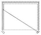
まず、本実施形態における情報処理システムの概略構成を図1A、図1Bを用いて説明する。図1Aは実施形態における情報処理システムの画像表示・入力部の外観斜視図、図1Bはこの情報処理システムのハードウェア構成を示すブロック図である。(Schematic configuration of coordinate input device)
First, a schematic configuration of the information processing system in the present embodiment will be described with reference to FIGS. 1A and 1B. FIG. 1A is an external perspective view of an image display / input unit of the information processing system in the embodiment, and FIG. 1B is a block diagram showing a hardware configuration of the information processing system.
この情報処理システムは、画像を表示する表示装置としてのプロジェクター7、このプロジェクター7の画像表示面7a上に設けられる座標入力装置8、プロジェクター7および座標入力装置8にそれぞれ接続され、両者を制御する制御装置(ホスト装置)としてのホストコンピュータ6を含む構成である。ホストコンピュータ6は例えばパーソナルコンピュータ(PC)によって実現されるものである。したがって、プロジェクター7および座標入力装置8はそれぞれ、例えばUSBなどのインタフェースを介してホストコンピュータ6に接続されうる。 This information processing system is connected to and controls a
座標入力装置8の構成について説明すると、図1Bにおける1L、1Rはそれぞれ、投光器および検出器を有するセンサユニットであり、1Lと1Rとは互いに所定の距離だけ離れた位置に設置されている。センサユニット1L、1Rは、制御・演算を行う制御・演算ユニット2に接続され、制御信号を制御・演算ユニット2から受け取ると共に、検出した信号を制御・演算ユニット2に送信する。3は、図2のように入射光をその到来方向に反射する再帰反射面を有する反射部材であり、左右それぞれのセンサユニットから入力領域5の面に沿ってその入力領域5を覆う範囲(例えば略90°の範囲)に投光された光を、センサユニットに向けて再帰反射する。反射光は、集光光学系とラインCCD等によって構成されたセンサユニットの検出器によって1次元的に検出され、その光量分布が制御・演算ユニット2に送られる。 The configuration of the
入力領域5は、PDPやリアプロジェクタ、LCDパネルなどの表示装置の表示画面上に構成されることで、インタラクティブな入力装置として利用可能となっている。このシステムでは、所定の指示具4を入力領域5に押圧等し移動させることで軌跡4aの入力が可能であり、また、表示されるアイコンなどの様々な情報に対して指示入力することで、各種アプリケーションのコントロールが可能となっている。 The
このような構成において、入力領域に指示具4あるいは指などによる入力指示がなされると、上記投光器から投光された光が遮られ、再帰反射による反射光が得られなくなるため、入力指示位置のみ光量が得られなくなる。 In such a configuration, when an input instruction is given to the input area with the
制御・演算ユニット2は、左右のセンサユニット1L、1Rの光量変化から、入力指示された部分の遮光範囲を検出し、同範囲内での検出点を特定してそれぞれの角度を算出する。算出された角度および、センサユニット間の距離等から、入力領域5上の座標位置を算出し、ホストコンピュータ6にその座標値を出力する。 The control /
このようにして、指などによって、画面上に線を描画したり、アイコンの操作するなどホストコンピュータ6の操作が可能になる。 In this way, the host computer 6 can be operated with a finger or the like to draw a line on the screen or operate an icon.
以下、座標入力装置8の各部分毎についての詳細説明を行う。 Hereinafter, each part of the coordinate
(センサユニットの詳細説明)
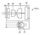
図3は、センサユニット1L、1Rにおける投光器の構成例を示す図で、(A)は投光器を上から(入力面に対し垂直方向)から見た図、(B)は横(入力面に対し水平方向)から見た図である。31は赤外光を発する赤外LEDであり、発光した光は投光レンズ32によって、略90°範囲に光が射出する。この方向では、赤外LED31からの光は上下方向に制限された光束として投光され、主に反射器3に対して光が投光されるようになっている。(Detailed explanation of sensor unit)
3A and 3B are diagrams showing a configuration example of a projector in the
図4は、センサユニット1L、1Rにおける検出器を入力面に対して垂直方向から見た図である。検出器は、1次元のラインCCD41および集光光学系としてのレンズ42,43および、入射光の入射方向を制限する絞り44、可視光など余分な光の入射を防止する赤外フィルター45を有する構成である。 FIG. 4 is a diagram of the detectors in the
投光器からの光は再帰反射部材によって反射され、赤外フィルター45、絞り44を抜けて、集光用レンズ42,43によって入力面の略90°範囲の光がCCD41の検出面にその入射角に依存した画素上に結像され、角度ごとの光量分布を示す。つまり画素番号が角度情報を表すことになる。 The light from the projector is reflected by the retroreflective member, passes through the
図5は、入力面を水平方向からの見たときのセンサユニット1L、1Rの構成を示している。図示のように、上記投光器と検出器とが重なるように構成されている。投光器と検出器の光軸間の距離は再帰反射部材の角度特性から充分検出可能な範囲に設定されていればよい。 FIG. 5 shows the configuration of the
(反射部材について)
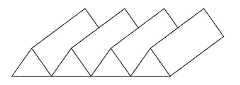
図1に示した再帰性反射部材3は、入射角度に対する反射特性を有している。図6に示す入射角度に対する反射光量の特性図からわかるように、再帰性反射部材3が平坦に構成された場合には、反射部材からの角度が45度を超えるあたりから得られる反射光量が減少し、遮蔽物があった場合にその変化が十分に取れないことになる。(Reflecting member)
The
反射光量は、光量分布(照明強度および距離)、反射部材の反射率(入射角度、反射部材の幅)、結像系照度(cosine4乗則)によって決まる。光量が足りない場合に、照明強度を上げることが考えられるが、反射分布が均一で無い場合には、強い部分の光を受光したときに、受光手段であるCCDでその部分が飽和することがあり、照明強度を上げるには限界がある。裏返せば、反射部材の反射の分布をなるべく均一にすることで低光量部分への入射光量の増大も望むことができる。 The amount of reflected light is determined by the light amount distribution (illumination intensity and distance), the reflectance of the reflecting member (incident angle, the width of the reflecting member), and the imaging system illuminance (cosine fourth law). When the amount of light is insufficient, it is conceivable to increase the illumination intensity. However, if the reflection distribution is not uniform, when a strong portion of light is received, the portion may be saturated by the CCD as the light receiving means. There is a limit to increasing the illumination intensity. In other words, it is also possible to increase the amount of light incident on the low light amount portion by making the reflection distribution of the reflecting member as uniform as possible.
角度方向に対して均一化を図るために、再帰性反射部材3を貼り付ける部材を図7に示すような三角柱を並べた形とし、この上に再帰反射部材3を設置している。これにより、角度特性を改善することができる。なお、三角柱の角度は再帰反射部材の反射特性から決定すればよく、また、そのピッチはCCDでの検出分解能以下に設定するのが望ましい。 In order to make the angle direction uniform, the member to which the
(制御・演算ユニットの説明)
図1に示した制御・演算ユニット2とセンサユニット1L,1Rとの間では、CCDの制御信号、CCD用クロック信号とCCDの出力信号、および、LEDの駆動信号がやり取りされている。(Explanation of control / arithmetic unit)
A CCD control signal, a CCD clock signal and a CCD output signal, and an LED drive signal are exchanged between the control /
図8は、制御・演算ユニット2の構成を示すブロック図である。CCD制御信号は、ワンチップマイコンなどで構成される演算制御回路(CPU)83から出力されており、CCDのシャッタタイミングや、データの出力制御などを行っている。CCD用のクロックはクロック発生回路87からセンサユニット1L、1Rに送られると共に、CCDとの同期をとって、各種制御を行うために、演算制御回路83にも入力されている。 FIG. 8 is a block diagram showing the configuration of the control /
LED駆動信号は、演算制御回路83からLED駆動回路84L,84Rを経て、センサユニット1L、1Rの赤外LEDに供給されている。 The LED drive signal is supplied from the
センサユニット1L、1Rの検出器におけるCCDからの検出信号は、A/Dコンバータ81L,81Rに入力され、演算制御回路83からの制御によって、デジタル値に変換される。変換されたデジタル値はメモリ(例えばRAM)82に記憶され、角度計算に用いられる。計算された角度から座標値が求められると、その座標値データがホストコンピュータ6に出力される。 Detection signals from the CCDs in the detectors of the
(光量分布検出の説明)
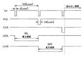
図9は、LED発光に係る各制御信号のタイミングチャートである。(Explanation of light intensity distribution detection)
FIG. 9 is a timing chart of each control signal related to LED light emission.
信号SH、ICGL、ICGRはCCD制御用の制御信号であり、SHの間隔でCCDのシャッタ解放時間が決定される。信号ICGL、ICGRはそれぞれ左右のセンサユニット1L,1Rへのゲート信号であり、CCD内部の光電変換部の電荷を読み出し部へ転送する信号である。信号LEDL、LEDRはそれぞれ、左右のLEDの駆動信号であり、SHの最初の周期で一方のLEDを点灯するために駆動信号LEDLがLED駆動回路を経てLEDに供給される。次の周期でもう一方のLEDが駆動される。双方のLEDの駆動が終了した後に、CCDの信号が左右のセンサから読み出される。 Signals SH, ICGL, and ICGR are control signals for CCD control, and the shutter release time of the CCD is determined by the interval of SH. Signals ICGL and ICGR are gate signals to the left and
読み出される信号は、入力がない場合には、それぞれのセンサからの出力として、図10のような光量分布が得られる。もちろん、このような分布がどのシステムでも必ず得られるわけではなく、再帰性反射部材3の特性やLEDの特性、また、経時変化(反射面の汚れなど)によって分布は変化する。同図においては、Aのレベルが最大光量であり、Bのレベルが最低のレベルとなる。つまり反射光のない状態では、得られるレベルがB付近になり、反射光量が増えるほどAのレベルの方向になっている。このようにCCDから出力されたデータは、逐次AD変換されCPUにデジタルデータとして取り込まれる。 When the signal to be read is not input, a light amount distribution as shown in FIG. 10 is obtained as an output from each sensor. Of course, such a distribution is not necessarily obtained in any system, and the distribution changes depending on the characteristics of the
図11は、指などで入力を行った、つまり、反射光を遮った場合の出力の例である。Cの部分が指などで反射光が遮られたため、その部分のみ光量が低下している。検出は、この光量分布の変化から行う。具体的には、図10のような入力の無い初期状態を予め記憶しておいて、それぞれのサンプル期間に図11のような変化があるか初期状態との差分によって検出し、変化があったらその部分を入力点として入力角度を決定する演算を行う。 FIG. 11 shows an example of output when input is performed with a finger or the like, that is, when reflected light is blocked. Since the reflected light is blocked by a finger or the like in the portion C, the amount of light is reduced only in that portion. Detection is performed from the change in the light amount distribution. Specifically, an initial state without input as shown in FIG. 10 is stored in advance, and whether there is a change as shown in FIG. 11 in each sample period is detected by a difference from the initial state. An operation for determining an input angle is performed using that portion as an input point.
(角度計算の説明)
角度計算にあたっては、まず、遮光範囲を検出する必要がある。先にも述べたように、光量分布は経時変化などで一定ではないため、システムの起動時などに記憶することが望ましい。そうすることで、例えば、再帰反射面がほこりなどで汚れていても、完全に反射しないような場合を除いて使用可能になる。以下、一方のセンサのデータについて説明するが、他方でも同様の処理を行っている。(Description of angle calculation)
In calculating the angle, it is first necessary to detect the light shielding range. As described above, since the light quantity distribution is not constant due to changes over time, it is desirable to store it at the time of starting up the system. By doing so, for example, even if the retroreflective surface is dirty with dust or the like, it can be used unless it is not completely reflected. Hereinafter, the data of one sensor will be described, but the same processing is performed on the other sensor.
電源投入時、入力の無い状態で、まず投光器から照明すること無しにCCDの出力をAD変換して、これをBas_data[N]として、メモリに記憶する。これは、CCDのバイアスのばらつき等を含んだデータとなり、図10におけるBのレベル付近のデータとなる。ここで、Nは画素番号であり、有効な入力範囲に対応する画素番号が用いられる。 When the power is turned on, the CCD output is first AD-converted without illumination from the projector in the absence of input, and this is stored in the memory as Bas_data [N]. This is data including variations in the bias of the CCD and the like, and is data near the level B in FIG. Here, N is a pixel number, and a pixel number corresponding to an effective input range is used.
次に、投光器から照明した状態での光量分布を記憶する。図10の実線で表されたデータであり、Ref_data[N]とする。これらのデータを用いてまずは入力がなされたか、遮光範囲があるかどうかの判定を行う。あるサンプル期間のデータをNorm_data[N]とする。 Next, the light quantity distribution in the state illuminated from the projector is stored. This data is represented by the solid line in FIG. 10 and is Ref_data [N]. Using these data, it is first determined whether an input has been made or whether there is a light shielding range. Data of a certain sample period is assumed to be Norm_data [N].
まず遮光範囲を特定するために、データの変化の絶対量によって、有無を判定する。これは、ノイズなどによる誤判定を防止し、所定量の確実な変化を検出するためである。変化の絶対量を各々の画素において以下の計算を行い、予め決定してある閾値Vthaと比較する。 First, in order to specify the light shielding range, presence / absence is determined based on the absolute amount of change in data. This is to prevent erroneous determination due to noise or the like and to detect a certain amount of reliable change. The absolute amount of change is calculated for each pixel as follows and compared with a predetermined threshold value Vtha.
Norm_data_a[N]=Norm_data[N]−Ref_data[N] (1) Norm_data_a [N] = Norm_data [N] −Ref_data [N] (1)
ここで、Norm_data_a[N]は各画素における絶対変化量である。 Here, Norm_data_a [N] is an absolute change amount in each pixel.
この処理は、差をとり比較するだけなので、処理時間をさほど使わないので、入力の有無の判定を高速に行うことが可能である。Vthaを初めて超えた画素が所定数を超えて検出されたときに入力があったと判定する。 Since this process only takes a difference and compares it, it does not use much processing time, and therefore it is possible to determine whether or not there is an input at high speed. When the number of pixels exceeding Vtha for the first time is detected exceeding a predetermined number, it is determined that there is an input.
次に、より高精度に検出するために、変化の比を計算して入力点の決定を行う。 Next, in order to detect with higher accuracy, a change ratio is calculated to determine an input point.
図12において、121は反射部材3の再帰反射面を示している。ここで領域Aが汚れなどにより反射率が低下していたとすると、このときのRef_data[N]の分布は、図13の(a)のように、領域Aの反射光量が少なくなる。この状態で、図12のように指などの指示具が挿入され、再帰反射部材のほぼ半分を覆ったとすると、反射光量は略半分となるため、図13の(B)の太線で示した分布Norm_data[N]が観測される。 In FIG. 12,
この状態に対して、式(1)を適用すると、図14の(a)のようになる。ここで、縦軸は初期状態との差分電圧になっている。このデータに対して、閾値を適用すると、本来の入力範囲をはずれてしまうような場合がある。もちろん、閾値を下げればある程度検出可能であるが、ノイズなどの影響を受ける可能性がある。 When Expression (1) is applied to this state, the result is as shown in FIG. Here, the vertical axis represents the differential voltage from the initial state. If a threshold is applied to this data, the original input range may be lost. Of course, it can be detected to some extent if the threshold value is lowered, but it may be affected by noise or the like.
そこで、変化の比を計算することとすると、領域A、Bとも反射光量は最初の半分であるので、次式で比を計算する。 Therefore, if the ratio of change is calculated, the amount of reflected light is half of the first half in both areas A and B, and therefore the ratio is calculated by the following equation.
Norm_data_r[N]=Norm_data_a[N]/(Bas_data[N]−Ref_data[N]) (2) Norm_data_r [N] = Norm_data_a [N] / (Bas_data [N] −Ref_data [N]) (2)
この計算結果を示すと、図14の(B)のようになり、変動比であらわされるため、反射率が異なる場合でも、等しく扱うことが可能になり、高精度に検出が可能になる。 This calculation result is as shown in FIG. 14B and is represented by a fluctuation ratio. Therefore, even when the reflectance is different, it can be handled equally and detection can be performed with high accuracy.
このデータに対して、閾値Vthrを適用して、その立ち上がり部と立下り部の画素番号から、両者の中央を入力画素として、角度を求める。図14の(B)は説明のために模式的に描いたもので、実際にはこのような立ち上がりにはなっておらず、画素ごとに異なるレベルを示している。 The threshold value Vthr is applied to this data, and the angle is obtained from the pixel numbers of the rising and falling portions with the center of both as the input pixel. FIG. 14B is schematically drawn for explanation, and does not actually rise like this, and shows a different level for each pixel.
図15は比計算を終えた後の検出の例である。いま閾値Vthrで検出すると遮光領域の立ち上がり部分は、Nr番目の画素で閾値を超えたとする。さらに、Nf番の画素でVthrを下回ったとする。このまま中心画素Npを、
Np=Nr+(Nf−Nr)/2 (3)
のように計算してもよいが、そうすると、画素間隔が最小の分解能になってしまう。より細かく検出するために、それぞれの画素のレベルとその一つ前の画素のレベルを用い閾値を横切った仮想の画素番号を計算する。FIG. 15 shows an example of detection after the ratio calculation is completed. Rising portion of the light shielding region now be detected in the threshold Vthr is to exceed the threshold value in Nr th pixel. Further, the below the Vthr at pixels numbered Nf. The central pixel Np is
Np = Nr + (Nf −Nr ) / 2 (3)
However, in this case, the pixel interval becomes the minimum resolution. In order to detect more finely, a virtual pixel number across the threshold is calculated using the level of each pixel and the level of the previous pixel.
今、NrのレベルをLr、Nr-1番画素のレベルをLr-1とする。また、NfのレベルをLf、Nf-1番がそのレベルをLf-1とすれば、それぞれの仮想画素番号Nrv,Nfvは、次式で計算できる。Now,assume that the level of Nr isLr , and the level of theNr- 1th pixel isLr-1 .If the level of Nf is Lf and the level of Nf-1 is Lf-1 , the virtual pixel numbers Nrv and Nfv can be calculated by the following equations.
Nrv = Nr-1 + ( Vthr - Lr-1 ) / ( Lr - Lr-1 ) (4)
Nfv = Nf-1 + ( Vthr - Lf-1 ) / ( Lf - Lf-1 ) (5)Nrv = Nr-1 + (Vthr-Lr-1 ) / (Lr -Lr-1 ) (4)
Nfv = Nf-1 + (Vthr-Lf-1 ) / (Lf -Lf-1 ) (5)
また、仮想中心画素Npvは次式で表される。The virtual center pixel Npv is expressed by the following equation.
Npv = Nrv + (Nfv-Nrv)/2 (6)Npv = Nrv + (Nfv -Nrv ) / 2 (6)
このように、画素番号とそのレベルから仮想的な画素番号を計算することで、より分解能の高い検出ができる。 Thus, by calculating a virtual pixel number from the pixel number and its level, detection with higher resolution can be performed.
得られた中央画素番号から、実際の座標値を計算するためには、角度情報に変換する必要がある。後述する実際の座標計算では、角度そのものよりもその角度における正接(tangent)の値を求めるほうが都合がよい。画素番号から、tanθへの変換には、テーブル参照や変換式を用いる。 In order to calculate an actual coordinate value from the obtained center pixel number, it is necessary to convert it into angle information. In actual coordinate calculation described later, it is more convenient to obtain the value of the tangent at the angle rather than the angle itself. A table reference or a conversion formula is used for conversion from the pixel number to tan θ.
図16は、画素番号に対するtanθ値をプロットしたものである。このデータに対して近似式を求め、その近似式を用いて画素番号、tanθ変換を行う。変換式は例えば高次の多項式を用いると精度を確保できるが次数などは計算能力および精度スペック等を鑑みて決定すればよい。 FIG. 16 is a plot of tan θ values against pixel numbers. An approximate expression is obtained for this data, and pixel number and tan θ conversion is performed using the approximate expression. For example, when a high-order polynomial is used as the conversion formula, the accuracy can be ensured, but the order and the like may be determined in consideration of the calculation capability and accuracy specifications.
5次多項式を用いる場合には係数が6個必要になるので、出荷時などにこのデータを不揮発性メモリーなどに記憶しておけばよい。 When a fifth order polynomial is used, six coefficients are required, so this data may be stored in a nonvolatile memory or the like at the time of shipment.
今5次多項式の係数をL5,L4,L3,L2,L1,L0としたとき、tanθは次式で表される。 If the coefficients of the fifth-order polynomial are now L5, L4, L3, L2, L1, and L0, tanθ is expressed by the following equation.
tanθ=((((L5*Npr+L4)*Npr+L3)*Npr+L2)*Npr+L1)*Npr+L0 (7)tanθ =(((( (L5 * Npr + L4) * Npr + L3) * Npr + L2) * Npr + L1) * Npr + L0 (7)
同様なことを各々のセンサに対して行えば、それぞれの角度データを決定できる。もちろん、上記例ではtanθを求めているが、角度そのものを求め、その後tanθを求めても構わない。 If the same thing is done for each sensor, the respective angle data can be determined. Of course, in the above example, tan θ is obtained, but the angle itself may be obtained, and then tan θ may be obtained.
(座標計算方法の説明)
得られた角度データから座標を算出する。(Explanation of coordinate calculation method)
Coordinates are calculated from the obtained angle data.
図17は、画面座標との位置関係を示す図である。入力範囲の下辺左右にそれぞれのセンサユニットが取り付けられており、その間の距離はDsで表されている。 FIG. 17 is a diagram illustrating a positional relationship with the screen coordinates. Each sensor unit is mounted on the left and right sides of the input range, and the distance between them is represented by Ds.
画面中央が画面の原点位置であり、P0はそれぞれのセンサユニットの角度0の交点である。それぞれの角度をθL、θRとして、それぞれtanθL,tanθRを上記多項式を用いて算出する。このとき点Pのx、y座標は次式で表される。 The center of the screen is the origin position of the screen, and P0 is the intersection of the
x=Ds/2 *(tanθL+tanθR)/(1+(tanθL*tanθR)) (8)
y=−Ds/2 *(tanθR - tanθL - (2*tanθL*tanθR))/(1+(tanθL*tanθR))+P0Y (9)x = Ds / 2 * (tanθL + tanθR) / (1+ (tanθL * tanθR)) (8)
y = −Ds / 2 * (tan θR−tan θL− (2 * tan θL * tan θR)) / (1+ (tan θL * tan θR)) + P0Y (9)
図18は、データ取得から座標計算までの工程を示した、フローチャートである。 FIG. 18 is a flowchart showing steps from data acquisition to coordinate calculation.
まず、ステップS101で電源投入されると、ステップS102で、演算制御回路83などのポート設定、タイマ設定などさまざまな初期化が行われる。ステップS103は立ち上げ時のみに行う不要電荷除去のための準備である。CCDなどの光電変換素子において、動作させていないときに不要な電荷が蓄積している場合があり、そのデータをそのままリファレンスデータとして用いると、検出不能になったり、誤検出の原因となる。それを避けるために、最初に照明無しで、複数回データの読み出しを行っている。ステップS103ではその読み込み回数を設定しており、ステップS104で照明無しで、所定回数データを読み出すことで、不要電荷の除去を行っている。 First, when the power is turned on in step S101, various initializations such as port setting and timer setting of the
ステップS105は所定回数繰り返すための判断文である。 Step S105 is a determination sentence for repeating a predetermined number of times.
ステップS106はリファレンスデータとしての照明無しでのデータの取り込みであり、上記Bas_dataに相当する。ここで取り込んだデータはメモリに記憶され(ステップS107)、以降計算に用いられる。これともう一つのリファレンスデータである、照明したときの初期光量分布に相当するデータRef_dataを取り込み(ステップS108)、これもメモリーに記憶する(ステップS109)。このステップまでが、電源投入時の初期設定動作になり、次から通常の取り込み動作になる。 Step S106 is fetching data without illumination as reference data, and corresponds to Bas_data. The data fetched here is stored in the memory (step S107) and used for the calculation thereafter. This and another reference data, that is, data Ref_data corresponding to the initial light amount distribution when illuminated is captured (step S108), and is also stored in the memory (step S109). Up to this step is the initial setting operation when the power is turned on, and then the normal capturing operation is performed.
ステップS110で上記説明したように光量分布を取り込み、ステップS111でRef_dataとの差分値で遮光部分の有無を判定する。無いと判定されたときには、ステップS110に戻り再び取り込みを行う。 In step S110, the light amount distribution is captured as described above, and in step S111, the presence / absence of a light-shielding portion is determined based on the difference value from Ref_data. If it is determined that there is not, the process returns to step S110 and the capture is performed again.
このとき、この繰り返し周期を10[msec]程度に設定すれば、100回/秒のサンプリングになる。 At this time, if the repetition period is set to about 10 [msec], the sampling rate is 100 times / second.
ステップS112で遮光領域が有りと判定されたら、ステップS113で式(2)の処理により比を計算する。得られた比に対して閾値で立ち上がり部、立下り部を決定し、(4)、(5)、(6)式で中心を計算する(ステップS114)。得られた中心値から近似多項式よりtanθを計算し(ステップS115)、左右のセンサユニットでのtanθ値からx、y座標を(8)、(9)式を用いて算出する(ステップS116)。 If it is determined in step S112 that there is a light-shielding region, the ratio is calculated in step S113 by the processing of equation (2). A rising portion and a falling portion are determined by a threshold with respect to the obtained ratio, and the center is calculated by the equations (4), (5), and (6) (step S114). From the obtained central value, tan θ is calculated from an approximate polynomial (step S115), and x and y coordinates are calculated from the tan θ values of the left and right sensor units using equations (8) and (9) (step S116).
次にステップS117にてタッチされたか否かの判定を行う。これは、例えばマウスのボタンを押下せずにカーソルを移動させている状態のような近接入力状態と、左ボタンを押した状態であるタッチダウン状態の判定を行っている。実際には、先に得られた比の最大値が、ある所定値例えば0.5などの値を超えていればダウンと判定し、それ以下なら近接入力状態と判定する。この結果に従って、ダウンフラグのセット(ステップS118)あるいはリセット(ステップS119)を行う。 Next, in step S117, it is determined whether or not it has been touched. For example, a proximity input state in which the cursor is moved without pressing a mouse button and a touch-down state in which the left button is pressed are determined. Actually, if the maximum value of the ratio obtained previously exceeds a certain predetermined value, for example, 0.5, it is determined that the input is in the proximity input state. According to this result, the down flag is set (step S118) or reset (step S119).
座標値とダウン状態が決定されたので、そのデータをホストコンピュータ6へ送信する(ステップS120)。ホストコンピュータ6は、ドライバが受信データを解釈し、カーソルの移動、マウスボタン状態の変更などを座標値、フラグなどを参照して行う。 Since the coordinate value and the down state are determined, the data is transmitted to the host computer 6 (step S120). In the host computer 6, the driver interprets the received data, and moves the cursor, changes the mouse button state, etc. with reference to the coordinate values, flags, and the like.
ステップS120の処理が終了したら、ステップS110の動作に戻り、以降電源OFFまでこの処理を繰り返すことになる。 When the process of step S120 is completed, the process returns to the operation of step S110, and thereafter this process is repeated until the power is turned off.
(座標入力用ペンの説明)
本実施形態における座標入力装置では、指での入力が可能であるが、ペンなどの指示具で入力を行うことによって、マウスの各種ボタンに対応する操作を直感的に操作することが可能となる。本実施形態における座標入力用ペン(以下「指示具」あるいは「ペン」ともいう。)4について、図19を用いて説明する。(Explanation of coordinate input pen)
In the coordinate input device according to the present embodiment, input with a finger is possible. However, by performing input with a pointing tool such as a pen, operations corresponding to various buttons of the mouse can be intuitively operated. . A coordinate input pen (hereinafter also referred to as “indicator” or “pen”) 4 according to the present embodiment will be described with reference to FIG.
本実施形態における指示具4は、筆記具であるところのペン先端部を押圧することで動作するペン先スイッチ(SW)41、並びに指示具4の筐体に設けられた複数のペンサイドスイッチ(SW)42を具備する。このいずれかのスイッチが動作することによって、指示具4から所定周期で信号を送信することになる。具体的には、駆動回路45は、所定周期毎にタイミング信号およびコマンド信号であるところの光信号を放射する。 The
その光信号は制御信号検出回路86(図8を参照)によって受光される。制御信号検出回路86は受光した光信号に基づき指示具4のどのスイッチが動作をしているかを判定する。同時に、センサユニット1L,1Rの間で、CCDの制御信号、CCD用クロック信号およびLEDの駆動信号のやり取りが開始される。具体的には、指示具4がタイミング信号として放射する光信号にスイッチ情報を示す信号を重畳(その他に例えば座標入力ペンを識別するための識別コード等を重畳させることも可能)させるものであるが、その情報を伝送する方法は、例えば連続するパルス列からなるリーダ部と、これに続くコード(メーカーIDなど)とからなるヘッダ部をまず出力し、その後ペンスイッチ信号等の制御信号などからなる送信データ列を予め定義された順序と形式に従って順次出力する。この方法はよく知られた方法(例えば赤外線を利用したリモコン等)であり、ここでの詳述は省略する。 The optical signal is received by the control signal detection circuit 86 (see FIG. 8). The control
またその他の方法としては、例えば所定周期毎に座標検出を行うこの種の座標入力装置の所定周期を変更し、その情報を検出することにより識別することも可能である。座標入力装置が最大100ポイント/秒、つまり10msec毎に座標検出可能な仕様とすれば、ペン先SW41が動作している場合には、例えば100ポイント/秒で座標算出を行い、ペンサイドSW42が動作している場合には、80ポイント/秒で座標算出するように設定、つまり、各々その周期で指示具4から信号を放射することになるので、その周期を制御信号検出回路86で監視することによって、どのスイッチが動作しているかを判別することが可能となる。 As another method, for example, it is also possible to change the predetermined period of this type of coordinate input device that performs coordinate detection every predetermined period and to detect the information by detecting the information. If the coordinate input device is designed to detect coordinates at a maximum of 100 points / second, that is, every 10 msec, when the
上記指示具4のさらに具体的な構成については後述する。 A more specific configuration of the
指示具4の先端を入力領域5に押圧すると、ペン先スイッチ41がON状態になり、操作者によってまさに座標入力が行われ、筆跡を入力しようとする状態(「ペンダウン」状態)となる。また例えばペン先スイッチを所定時間内に2回動作させた場合、座標入力装置の座標サンプリングレートを参照しながら、信号を受信した時間、間隔、あるいは座標を算出しているタイミング等を監視することで、マウスのダブルクリック動作を認識するように構成されている。 When the tip of the
(座標入力用ペンのアップダウンの説明)
つづいて、図20のフローチャートを用いて、ペン/アップダウンについて説明する。(Explanation of coordinate input pen up / down)
Next, pen / up / down will be described with reference to the flowchart of FIG.
まずステップS402でペン先スイッチ41の状態を判定する。ペン先スイッチ41がON状態とは、入力領域5上に座標入力ペンが位置し、操作者によってまさに座標入力が行われ、筆跡を入力しようとする状態(「ペンダウン」状態)であり、画面上に表示された筆跡は、操作者による筆記動作に対して忠実に再現される。また例えばペン先スイッチを所定時間内に2回動作させた場合、座標入力装置の座標サンプリングレートを参照しながら、信号を受信した時間、間隔、あるいは座標を算出しているタイミング等を監視することで、マウスのダブルクリック動作を認識するように構成されている。 First, in step S402, the state of the
一方ステップS402でペン先スイッチが動作していない(OFF状態)場合は、ステップS403〜S405において、ペンサイドスイッチの状態を判別する。本実施形態においては、指示具4にはペンサイドスイッチ42a、42bの2個のサイドスイッチ42が具備されており、どちらか一方だけがON状態にあれば、「ペンアップ」状態、その両者がON状態となっていれば「ペンダウン」状態として動作する。 On the other hand, if the pen tip switch is not operating (OFF state) in step S402, the state of the pen side switch is determined in steps S403 to S405. In this embodiment, the
このようにペン先スイッチ41がOFF状態で、かつ、42aまたは42bの少なくとも一方のサイドスイッチが動作状態(ON状態)となっているときは、操作者が入力領域5から浮かせた位置で、画面を制御しようとしている場合であり、浮かせた位置で例えばカーソルを所望の位置に移動したり、筆跡を入力しようとする場合である(以下、この入力状態を「近接入力」という。)。具体的には、サイドスイッチ42a、42bのいずれか一方だけが動作しているペンアップ状態では、操作者は画面上に示されているカーソルを移動させることができ、その両者が動作しているペンダウン状態では、後述するような態様で指示具4の移動軌跡を筆跡として表示することができる。これを実現すべく、座標入力装置が座標を算出する際に、ペンの状態(ペンアップ、ペンダウン)を情報として同時に出力することができるように構成してあるので、その情報を基にホストコンピュータ6に格納されている制御ソフト、或いはアプリケーションソフト等によって、所望の動作を実現することができる。 As described above, when the
一方、指示具4のいずれかのスイッチが動作している状態は、常に所定周期での座標算出、つまり指示具4から信号が所定周期で放出されている状態である。したがって、このタイミング信号であるところの光信号を所定周期毎に検出できるかどうかによって、最初の座標を検知した状態から、連続的に座標が入力されている状態にあるのか、連続的に座標入力が行われている状態が中断した状態にあるのかを判定することができる。つまり、制御信号検出回路86のスタート信号の発生タイミングを監視(座標サンプリングレートを100回/秒とすれば、0.01秒毎にスタート信号が発生する)することによって、連続入力の状態にあるかどうかを判定することができる。 On the other hand, the state in which any switch of the
あるいは、連続入力を判定する手段として、所定時間を設定し、その所定時間内に信号(例えば本実施形態の場合には、スタート信号であるところの光信号)が検知されるか、あるいは座標値が検出されたかを判定するようにしてもよい。 Alternatively, as a means for determining continuous input, a predetermined time is set, and a signal (for example, an optical signal that is a start signal in the present embodiment) is detected within the predetermined time, or a coordinate value It may be determined whether or not is detected.
(複数の指示具による入力座標の検出に関する説明)
上記では、各センサユニットのCCDで検出される遮光の数がそれぞれ1個づつの場合(入力座標が1個のみ)について述べた。ここからは、複数の操作者が各々の指示具で入力する場合に、複数の入力座標値を算出しホストコンピュータ6に出力する場合について説明する。(Explanation regarding detection of input coordinates with multiple indicators)
In the above description, the case where the number of light shielding detected by the CCD of each sensor unit is one each (only one input coordinate) is described. From here, a case where a plurality of input coordinate values are calculated and output to the host computer 6 when a plurality of operators input with the respective pointing tools will be described.
この場合、指示具の数と同じ数だけ算出した複数の座標値をホストコンピュータ6に出力する際には、各座標値にその指示具の属性の情報を付加したうえで出力する必要がある。すなわち、各指示具で入力した座標値のそれぞれが各々の指示具ごとに連続するような入力軌跡として表示させるためには、どの指示具で入力された座標値であるかをコンピュータに認識させる必要がある。そこで、本実施形態では、指示具が発光する光信号を制御信号検出回路86で検出する以外に各センサユニットでも検出する構成を採る。 In this case, when outputting a plurality of coordinate values calculated by the same number as the number of pointing tools to the host computer 6, it is necessary to add the attribute information of the pointing tool to each coordinate value before outputting. That is, in order to display each input coordinate value input with each pointing tool as an input locus that is continuous for each pointing tool, it is necessary for the computer to recognize which pointing tool is the coordinate value input. There is. Therefore, in the present embodiment, a configuration is adopted in which each sensor unit detects an optical signal emitted from the pointing tool in addition to being detected by the control
図21は、複数の指示具を使用した場合における各制御信号およびCCDの検出信号のタイミングチャートである。 FIG. 21 is a timing chart of each control signal and CCD detection signal when a plurality of pointing tools are used.
いま、2本の指示具で入力を行なうとして、それぞれをペン1およびペン2とすると、信号(1)、(2)はそれぞれ、指示具であるペン1およびペン2が送信するペン制御信号を示している。このペン制御信号は赤外線のデータ列となっていて、このデータ列のうち前半の(a)および(a’)はスイッチ信号を示しており、後半の(b)および(b’)はID信号を示している。 Assuming that input is performed with two pointing tools, and pens 1 and 2 are respectively used, signals (1) and (2) are pen control signals transmitted by
信号(3)、(4)は、ペン制御信号(1)、(2)に応じて演算制御回路83で生成される信号で、所定の周期で検出されるペン制御信号に従ってHi/Lowに切り替わる。 Signals (3) and (4) are signals generated by the
信号(5)、(6)は、CCD制御用の制御信号であり、先に説明したとおりであるので、ここでは説明を省略する。 Signals (5) and (6) are control signals for controlling the CCD, and are the same as described above.
先述のとおり、通常取り込み動作で検出されたCCDの検出波形(8)において、(h)および(i)のように遮光が2個検出された場合は、複数の入力があるものと判定する。なお、同図では片方のセンサユニットのCCDの検出波形のみを示しているが、どちらかのCCDで検出された遮光の数が少なくとも2個ある場合には複数の入力があるものと判定する。 As described above, in the detection waveform (8) of the CCD detected by the normal capturing operation, when two shades are detected as in (h) and (i), it is determined that there are a plurality of inputs. Although only the detection waveform of the CCD of one sensor unit is shown in the figure, if there are at least two light-shielding numbers detected by either CCD, it is determined that there are a plurality of inputs.
複数の入力があるものと判定された場合は、次に検出されるペン制御信号の最初のパルスの立上りに同期した(e)のタイミングに同期してCCD制御信号を送信する。そして、シャッターの(g)の区間で(d)のパルス幅に相当する光信号をCCDで検出する。このとき(7)の制御信号により、センサユニットの照明用のLEDはオフとして、CCDのダイナミックレンジに影響しないようにする。検出された波形は、例えば(8)の(j)、(k)のようになり、先に検出されて記憶した遮光(h)に対応する画素番号(l)と今回検出した(m)を比較して所定の範囲内の画素数であれば、遮光(h)はペン2の指示具によるものと判断することができる。 If it is determined that there are a plurality of inputs, the CCD control signal is transmitted in synchronization with the timing (e) synchronized with the rising edge of the first pulse of the pen control signal detected next. Then, an optical signal corresponding to the pulse width of (d) is detected by the CCD in the section (g) of the shutter. At this time, according to the control signal (7), the illumination LED of the sensor unit is turned off so as not to affect the dynamic range of the CCD. The detected waveforms are, for example, (j) and (k) in (8), and the pixel number (l) corresponding to the light shielding (h) detected and stored previously and (m) detected this time are detected. If the number of pixels is within a predetermined range, the light shielding (h) can be determined to be caused by the pointing tool of the
なお、シャッターの間隔(g)は、先にCCDで検出された遮光(h)、(i)の幅で適宜可変することでCCDのダイナミックレンジに影響しないように適切なレベルで検出が可能となる。すなわち、先に検出した遮光幅が広いときは、シャッターを短く、遮光幅が狭いときは、シャッターを長く制御する。 The shutter interval (g) can be detected at an appropriate level so as not to affect the dynamic range of the CCD by appropriately changing the width of the light shielding (h) and (i) previously detected by the CCD. Become. That is, when the previously detected light shielding width is wide, the shutter is controlled to be short, and when the light shielding width is narrow, the shutter is controlled to be long.
次に図22および図23を用いて、入力領域5の座標とCCDで検出される波形の例を用いて、遮光とペンのID信号の関連付けに関して説明する。 Next, with reference to FIG. 22 and FIG. 23, the association between the light shielding and the pen ID signal will be described using the coordinates of the
図22(1)は、入力領域5に黒丸で示すAとBの位置に入力があった場合を示している。この場合の概略のCCD検出波形は、センサユニット1Lでは、図23(1)(a)(L)および(1)(b)(L)のように観測され、一方のセンサユニット1Rでは、図23(1)(a)(R)および(1)(b)(R)のように観測される。このとき先述したように遮光QL1に対して計算された画素番号NL1とペンの検出光(制御信号)PL1に対応する画素番号NL2が所定の値の幅に入っているとして、QL1がPL1に対応するものと判定することができる。同様に、QR1がPR1に対応する遮光と判断することができる。したがって、いま入力を許可する指示具を2本とすると、2つの遮光の一方が決定されたので、もう一方は別の指示具によるものと判断することができる。 FIG. 22 (1) shows a case where the
ところで、図23(1)のそれぞれの遮光QL1,QL2,QR1,QR2を用いて座標を計算すると、図22(1)の座標A,B,A’,B’が計算されることとなり、実の座標A,Bと虚の座標A’,B’が計算されることとなり、正しい座標を算出するための虚実判定が必要となる。しかしながら、上述したようにあらかじめ指示具に対応する遮光の組み合わせを決定して、それぞれの組み合わせの遮光で算出されたCCD画素番号で座標計算すると、一意に座標A、Bを決定することができる。 By the way, when the coordinates are calculated using the respective light shields QL1, QL2, QR1, and QR2 in FIG. 23 (1), the coordinates A, B, A ′, and B ′ in FIG. 22 (1) are calculated. Coordinates A and B and imaginary coordinates A ′ and B ′ are calculated, and it is necessary to determine whether the coordinates are correct in order to calculate correct coordinates. However, as described above, when the light-shielding combination corresponding to the pointing tool is determined in advance and coordinates are calculated using the CCD pixel number calculated by the light-shielding of each combination, the coordinates A and B can be uniquely determined.
次に図22(2)のようにセンサユニット1Lから見たときに座標A、Bが略一直線上に並ぶ場合は、センサユニット側から見て入力が手前にあるペンの影響で後ろ側にある座標Bがセンサユニットから見えない状態となる。このときCCD検出波形は図23(2)(a)のように検出され、センサユニット1Lで検出される波形は、図23(2)(a)(L)のように遮光が1個だけ検出される状態となる。一方、センサユニット1Rで検出される波形は、図23(2)(a)(R)のように遮光が2箇所であるので複数の入力があるものと判断でき、ペン制御信号との対応関係を判断する。この場合、センサユニット1Lでは座標Aに対応するペンの信号のみがCCDで検出されるので、QL1と検出されたPL1が対応するものと判断することができる。そのとき、1RではPR1が検出されたとするとQR1とPR1が対応するものとして判断することができる。 Next, when the coordinates A and B are arranged in a substantially straight line when viewed from the
なお、このままでは座標Bは、図22(2)のB’の点として計算されてしまう。図22(2)のような場合には、Cで示す範囲でどの位置にBがあるかはこのままでは不明である。そこで、センサユニット1Rと座標Bまでの距離と遮光幅QR2の関係から導出される補正値kによって座標Bが算出される。この補正値kは、センサユニットと入力座標から算出される距離とCCDで検出される遮光幅の関係からあらかじめ算出され、テーブル情報としてメモリに記憶しておき、適宜演算制御回路から呼び出して使用される。また、このように遮光が重なった場合は、上記のように距離と幅の関係で補正する方法以外に、第3のセンサを設けて、片方の遮光が2個でもう一方が1個の場合は、センサを切替えて重ならない方向から検出するように構成してもよく、この場合であっても、高精度に座標が算出可能となる。 In this case, the coordinate B is calculated as a point B ′ in FIG. In the case of FIG. 22 (2), it is unclear as to which position B is in the range indicated by C. Therefore, the coordinate B is calculated from the correction value k derived from the relationship between the distance between the
図24は、複数の指示具の使用を考慮した遮光とペンIDとの対応付け処理を示すフローチャートである。以上のような複数の入力の判定処理は図24に示すフローチャートにしたがって動作する。このルーチンは、図18で示したフローチャートのステップS114から呼び出され、以下のように動作する。 FIG. 24 is a flowchart showing a process for associating light shielding with a pen ID in consideration of use of a plurality of pointing tools. A plurality of input determination processes as described above operate according to the flowchart shown in FIG. This routine is called from step S114 of the flowchart shown in FIG. 18, and operates as follows.
まず、ステップS202では先に算出した立上り、立下りの中心の画素番号の個数より遮光の数を判断し、遮光が2個あるセンサが少なくとも1つあれば、複数入力であると判断する。したがって、ステップS203で複数入力と判断された場合には、ステップS204で次のペン制御信号に同期したタイミングで照明無しデータの取り込みの処理を行なう。ステップS205で検出したデータをメモリに記憶して、ステップS206で遮光と指示具の制御信号による検出光との対応関係の判断処理を行なう。 First, in step S202, the number of shades is determined from the number of pixel numbers at the center of rising and falling previously calculated, and if there is at least one sensor with two shades, it is determined that there are multiple inputs. Therefore, if it is determined in step S203 that there are a plurality of inputs, in step S204, processing for capturing non-illuminated data is performed at a timing synchronized with the next pen control signal. The data detected in step S205 is stored in the memory, and in step S206, a process for determining the correspondence between the light shielding and the detected light based on the control signal of the pointing tool is performed.
そして、ステップS207でペンのID情報の読み込み処理を行い、ステップS208において、ステップS206で処理した遮光と指示具の制御信号の関連性から、遮光とペンIDの関連付けの処理を行ない、決定した値をステップS209でリターンする。なお、ステップS203で両方のセンサで遮光が1個づつの場合は、複数入力がないものと判断して、ステップS207の処理に移り、上記と同様に遮光とペンIDをステップS209でリターンする処理が行なわれる。 In step S207, the pen ID information is read. In step S208, the association between the shading and the pen ID is performed based on the association between the shading processed in step S206 and the control signal of the pointing tool. In step S209. Note that if there is one shading in both sensors in step S203, it is determined that there are no multiple inputs, the process proceeds to step S207, and the shading and pen ID are returned in step S209 as described above. Is done.
上記では、指示具4のSWを押したときにのみ指示具4から制御信号が送信される構成となっているが、近接入力時にID情報を付与する場合は、所定サンプルごとに指示具4のSWの操作がなくてもID信号を送信することで、遮光と制御信号の光の対応をつけて、近接入力を実現することができる。この場合は、制御信号の検出によるID信号はあるが、遮光がない場合は、ホストコンピュータ6には何も出力しない。遮光がありSW信号もある場合は、ペンSW信号を判断して近接入力として座標値にID信号を付与してホストコンピュータに座標情報を送信することで、近接入力時にもペンのID情報付きの処理が可能とすることができる。 In the above, the control signal is transmitted from the
また、例えば、複数のペン制御信号用の光が重畳するために、待機時間処理を増やすなどして、コンピュータに座標を送信する周期に問題が生じる場合などは、入力が検出された最初の座標点だけ指示具の属性判定を行なって、その後の座標の送信は、入力座標の連続性を示す情報を座標情報に付与して送信してもよい。この入力座標値の連続性の判断は、前回の座標値と今回の座標値との距離や、ベクトル情報などで判断することができる。 Also, for example, if there is a problem in the cycle of transmitting coordinates to the computer due to the increase in waiting time processing due to the overlap of light for multiple pen control signals, the first coordinate at which input was detected The attribute determination of the pointing tool is performed only for the points, and the subsequent transmission of the coordinates may be performed by giving information indicating the continuity of the input coordinates to the coordinate information. The continuity of the input coordinate values can be determined from the distance between the previous coordinate value and the current coordinate value, vector information, or the like.
また、上記では、CCDで検出された波形に対して、遮光の判断は、検出波形の立上り・立下りを算出し、その略中心の画素番号を求めていた。しかしながら、CCDのダイナミックレンジを考えた場合には、図27に示すように、CCDの最大許容電圧値Vmaxを超えるような入力があった場合に、その影響がその後の検出波形に及ぶことが考えられる。したがって、CCDが飽和する前の立下りの情報に対して、遮光との対応付けを行なってもよい。その場合は、遮光は立上り情報で判定したNL1、そしてペン制御信号の光は立下り情報で判定したNL2を算出し、それぞれを比較することによって各々が対応付けられることになる。 In the above description, for the waveform detected by the CCD, the determination of light shielding is performed by calculating the rise / fall of the detected waveform and obtaining the pixel number at the approximate center thereof. However, when considering the dynamic range of the CCD, as shown in FIG. 27, if there is an input that exceeds the maximum allowable voltage value Vmax of the CCD, it is possible that the influence will affect the subsequent detection waveform. It is done. Therefore, the falling information before the CCD is saturated may be associated with light shielding. In this case, NL1 determined by the rising information and NL2 determined by the falling information are calculated for the light shielding, and NL2 determined by the falling information is calculated.
また、上記では、入力する指示具が2本の場合について述べたが、指示具が3本以上の場合であっても、遮光の個数にしたがって、指示具の制御信号の光を順番に検出するように構成しておくことで、遮光と指示具の対応が可能となる。さらには、指とペンが混在した入力も可能であり、例えば遮光とペン制御信号光が関連付けられた遮光によって計算された座標値のみにID信号を付与し、ペン制御信号光が関連付けられない遮光については、指による入力と判断して、指による入力のフラグを座標値に付与することもできる。 Further, in the above description, the case where there are two indicating tools to be input has been described, but even when there are three or more pointing tools, the light of the control signal of the pointing tool is sequentially detected according to the number of light shielding. By configuring in this way, it is possible to correspond to the light shielding and the pointing tool. Furthermore, it is possible to input a mixed finger and pen. For example, an ID signal is given only to a coordinate value calculated by shading associated with light shielding and pen control signal light, and light shielding with no pen control signal light associated is performed. With respect to, it is also possible to determine that the input is made with a finger and add a flag for the input with the finger to the coordinate value.
同様の処理方法を使用すると、例えば、ペンのみの使用を許可し指の入力を禁止する仕様とする場合には、遮光とペン信号の関係が一致しないものに関しては誤検出として座標を出力しない処理を行なうことができる。これは、例えばペンで入力する際に袖や手付きが生じて遮光として検出されてしまった場合でも、ペンのみの座標を出力することを可能とするため、使い勝手のよい座標入力装置を提供することができる。 If the same processing method is used, for example, in the case of a specification that permits the use of only a pen and prohibits the input of a finger, a process that does not output coordinates as a false detection for a case where the relationship between the shading and the pen signal does not match Can be performed. This is to provide an easy-to-use coordinate input device, for example, in order to be able to output the coordinates of only the pen even when sleeves or hands are attached and input is detected as shading when inputting with a pen. Can do.
以上のように構成することで、指示具にあらかじめコンピュータ側で表示するための色情報を与えておくなど、指示具の属性に対応した様々な処理が可能となる。しかも、以上の処理は、ペンの制御信号用である光信号を座標検出用(遮光検出用)のCCDで検出するように構成するため、部品点数を増やすことなく安価に構成することができる。さらに、複数の座標値の各々に対して一意に決定する指示具の属性を付与してコンピュータに送信することができるので、コンピュータ上のアプリケーションを操作性良く、しかも機能に制限をもたせることなく複数人で使用することが可能な座標入力装置を提供することができる。 With the configuration as described above, various processes corresponding to the attributes of the pointing tool, such as giving color information to be displayed on the computer side to the pointing tool in advance, can be performed. In addition, the above processing is configured such that the optical signal for pen control signal is detected by the CCD for coordinate detection (light-shielding detection), so that it can be configured at low cost without increasing the number of parts. In addition, since it is possible to give an attribute of a pointing tool that is uniquely determined to each of a plurality of coordinate values and transmit it to a computer, it is possible to perform a plurality of applications on the computer with good operability and without restricting functions. A coordinate input device that can be used by a person can be provided.
(検出不能領域がある場合の説明)
指示具4を構成する赤外LED43(図19)からの光信号は、制御信号検出回路86において入力領域5の全域で検出されうる構成が望ましいが、場合によっては、指示具4におけるこの赤外LED43で構成される投光部材の位置(入力面からの高さ)とセンサユニットや筐体の位置関係によって、制御信号の光信号を全ての入力可能領域でセンサユニットが検出ができない状態が生じる場合がある。(Explanation when there is an undetectable area)
It is desirable that the optical signal from the infrared LED 43 (FIG. 19) constituting the
ここで、センサユニット1Lでは検出不能の領域が存在する場合について、図25および図23を用いて説明する。 Here, a case where there is a region that cannot be detected by the
図25において、領域Dが、センサユニット1Lでは検出不能の領域であるとする。この場合であっても、両方のセンサユニットで重なる検出不能領域が存在しなければ、遮光と指示具の光信号との対応付け判断処理を行なうことによって、座標値に指示具のID情報を付与することができる。 In FIG. 25, it is assumed that a region D is a region that cannot be detected by the
図25(1)に示すように、複数の入力点AおよびBの両方が検出不能領域Dに存在する場合、CCDで検出される波形は、図23(3)のようになる。図23(3)(a)の遮光であるかの判断は、上述した例と同様であるが、ここでは更に、遮光の幅を検出する。遮光の幅は、立上り情報および立下り情報から簡単に算出することができ、この遮光幅情報によって、入力が検出不能領域Dに存在するかどうかの判断を行なう。 As shown in FIG. 25 (1), when both of the plurality of input points A and B are present in the undetectable region D, the waveform detected by the CCD is as shown in FIG. 23 (3). The determination as to whether the light is blocked in FIG. 23 (3) (a) is the same as in the above-described example, but the width of the light is further detected here. The light shielding width can be easily calculated from the rising edge information and the falling edge information, and whether or not the input exists in the undetectable region D is determined based on the light shielding width information.
いま、遮光幅ΔNL1およびΔNL2が所定の幅を超えているので検出不能領域に存在すると判断した場合、センサユニット1Lの近傍に検出不能領域があると判断することができる。この場合、指示具の制御信号用光信号のCCD読出しは行なわないで、1R側のみ照明をオフにしてペンの制御信号でのCCD検出信号を読み出す動作を行なう。こうすることによって、読出しの時間を短縮することができるため処理を高速化することができる。 Now, if the light shielding widths ΔNL1 and ΔNL2 exceed the predetermined width, and it is determined that they exist in the undetectable region, it can be determined that there is an undetectable region in the vicinity of the
そして、いま遮光QR1と制御信号光PR1が対応付けられたので、ΔNL1>ΔNL2とすると、1Lに対して遮光QL1が距離が近いところにあるといえるので、1Rにおいては、角度が浅い方の遮光QR1が遮光QL1と対応付けることができ、すなわち遮光QL1と制御信号光PR1のペンIDが対応付けられる。 Since the light shield QR1 and the control signal light PR1 are now associated with each other, if ΔNL1> ΔNL2, it can be said that the light shield QL1 is close to 1L. QR1 can be associated with the light shielding QL1, that is, the light shielding QL1 and the pen ID of the control signal light PR1 are associated with each other.
また、図25(2)のように入力位置が制御信号光検出不能領域Dであり、1Rからみて略一直線に入力点が並んだ場合には、上記と同様に図23(4)(a)の遮光幅より、検出不能領域であることを判断したあと、1R側において、制御信号光を検出したPR1は、1Rに対して手前に存在する入力点なので、1L側からみると、角度が浅い方の遮光がPR1に対応する遮光と判断することができる。したがって、図23(4)(a)の遮光QL1がPR1に対応すると判断することができる。 Further, when the input position is the control signal light non-detectable region D as shown in FIG. 25 (2) and the input points are arranged substantially in a straight line as viewed from 1R, as in the above, FIG. 23 (4) (a) After judging that it is a non-detectable area from the shading width of 1, PR1 which detected the control signal light on the 1R side is an input point existing in front of 1R, so the angle is shallow when viewed from the 1L side. It can be determined that the light shielding of the other corresponds to the light shielding corresponding to PR1. Therefore, it can be determined that the light shielding QL1 in FIG. 23 (4) (a) corresponds to PR1.
以上のようにして、遮光と指示具のID情報を対応付けることができるので、複数の各座標値に指示具のID情報を付与して、ホストコンピュータ6に送信することができる。 As described above, since the shading can be associated with the ID information of the pointing tool, the ID information of the pointing tool can be assigned to each of the plurality of coordinate values and transmitted to the host computer 6.
ところで、この種の光を用いた座標入力装置は、投光した光が指示具に反射して、センサユニットに直接的に戻る現象(直接反射)が生じる場合がある。これは、指示具の塗装が反射率の高い材料で構成されているような表面状態の場合に生じることがあり、このとき図26のようなCCD検出波形になる。この場合には図26(a)の遮光の立上り・立下りを検出するだけでは、あたかもQL1とQL2の2個の遮光が存在するように判断されてしまう。しかし、ペンの制御信号の検出光と対応付けることで、図26(b)に示すようにペンの制御信号の検出光は1個なので、遮光はペンの直接的な反射光を含んだものであると判断することができる。したがって、指示具の直接反射が生じる場合であっても、誤検出を防止することが可能となる。 By the way, in the coordinate input device using this kind of light, a phenomenon (direct reflection) may occur in which the projected light is reflected by the indicator and returns directly to the sensor unit. This may occur in the case of a surface state in which the coating of the indicator is made of a material having a high reflectance, and at this time, a CCD detection waveform as shown in FIG. 26 is obtained. In this case, if only the rise / fall of the light shielding in FIG. 26A is detected, it is determined as if there are two light shieldings, QL1 and QL2. However, by associating with the detection light of the pen control signal, the detection light of the pen control signal is one as shown in FIG. 26B, and thus the light shielding includes the direct reflected light of the pen. It can be judged. Therefore, it is possible to prevent erroneous detection even when direct reflection of the pointing device occurs.
また、指示具の使用できる本数を制限することによって、例えば2本を許可する場合は、遮光の個数が3個の場合は、直接反射が含んでいると判断することができる。この場合であっても上記と同様に遮光とペンの制御信号の検出光とを対応付けることで、どの遮光が直接反射によるものかを判断することができる。 Further, by restricting the number of the pointing tools that can be used, for example, when two are permitted, it can be determined that direct reflection is included when the number of light shielding is three. Even in this case, it is possible to determine which light shielding is caused by direct reflection by associating the light shielding with the detection light of the pen control signal in the same manner as described above.
Claims (8)
Translated fromJapanese前記入力領域の周縁部に設けられ、前記投光器からの入射光を前記検出器に向けて反射させる反射部材と、
前記入力領域内の任意の位置を指示する指示操作を行うための指示具と、
前記センサユニットを用いて前記指示具の前記指示操作に伴う遮光を検出し、検出した前記遮光に基づいて前記位置の座標値を算出し、その座標値の情報を出力する制御ユニットと、
を備えた座標入力装置であって、
前記指示具は、前記指示操作に伴い、当該指示具を識別するための識別情報を含む光信号である制御信号を発信する手段を含み、
前記制御ユニットは、前記センサユニットに含まれる検出器で複数の遮光を検出した場合、前記検出器で検出した複数の遮光のうち、前記検出器で受信した前記制御信号に対応する遮光を判定し、前記検出器で受信した前記制御信号に含まれる前記識別情報を、前記制御信号に対応する遮光に基づいて算出した座標値の情報に付加して出力する
ことを特徴とする座標入力装置。A projector that projects a range covering the input area along the surface of the input area, and a sensor unit that includes a detector that detects incoming light;
A reflection member provided at a peripheral portion of the input region and reflecting incident light from the projector toward the detector;
An indicator for performing an instruction operation for instructing an arbitrary position in the input area;
A control unit that detects light shielding associated with the pointing operation of the pointing tool using the sensor unit, calculates a coordinate value of the position based on the detected light shielding, and outputs information of the coordinate value;
A coordinate input device comprising:
The pointing tool includes means for transmitting a control signal thatis anoptical signal including identification information for identifying the pointing tool in accordance with the pointing operation,
When the control unitdetects a plurality of light shieldings with a detector included in the sensor unit , the control unitdetermines a light shielding corresponding to the control signal received by the detector among the plurality of light shieldings detected by the detector. , the coordinate input device, characterized inthat the said identificationinformation included in the control signal receivedby thedetector, and outputs the added to thecalculated coordinate values of the informationbased on the light shielding corresponding to thecontrol signal.
前記入力領域の周縁部に設けられ、前記投光器からの入射光を前記検出器に向けて反射させる反射部材と、
前記入力領域内の任意の位置を指示する指示操作に伴って識別情報を含む光信号である制御信号を発信する指示具と、
を有する座標入力装置の制御方法であって、
前記センサユニットを用いて前記指示具の前記指示操作に伴う遮光を検出するステップと、
検出された前記遮光に基づいて、指示された前記位置の座標値を算出するステップと、
前記センサユニットに含まれる検出器で複数の遮光を検出した場合、前記検出器で検出した複数の遮光のうち、前記検出器で受信した前記制御信号に対応する遮光を判定するステップと、
前記検出器で受信した前記制御信号に含まれる前記識別情報を、前記制御信号に対応する遮光に基づいて算出した座標値の情報に付加して出力するステップと、
を有することを特徴とする座標入力装置の制御方法。A projector that projects a range covering the input area along the surface of the input area, and a sensor unit that includes a detector that detects incoming light;
A reflection member provided at a peripheral portion of the input region and reflecting incident light from the projector toward the detector;
An indicator thatemits a control signal,which is anoptical signal including identification information, in accordance with an instruction operation for instructing an arbitrary position in the input area;
A control method of a coordinate input device having
Detecting light shielding associated with the pointing operation of the pointing tool using the sensor unit;
Basedon the detected light shielding, and calculating the coordinate value of the indicated said position,
Determining a light shielding corresponding to the control signal received by the detector among a plurality of light shielding detected by the detector when detecting a plurality of light shielding by a detector included in the sensor unit;
A step in which the identificationinformation, added and outputs thecalculated information of coordinate valuesbased on the light shielding corresponding to thecontrolsignalincluded in the controlsignal received by thedetector,
A control method for a coordinate input device, comprising:
前記入力領域の周縁部に設けられ、前記投光器からの入射光を前記検出器に向けて反射させる反射部材と、
前記入力領域内の任意の位置を指示する指示操作に伴って識別情報を含む制御信号を発信する指示具と、
を有する座標入力装置の制御をコンピュータに実行させるためのプログラムであって、当該コンピュータに、
前記センサユニットを用いて前記指示具の前記指示操作に伴う遮光を検出するステップと、
検出された前記遮光に基づいて、指示された前記位置の座標値を算出するステップと、
前記センサユニットに含まれる検出器で複数の遮光を検出した場合、前記検出器で検出した複数の遮光のうち、前記検出器で受信した前記制御信号に対応する遮光を判定するステップと、
前記検出器で受信した前記制御信号に含まれる前記識別情報を、前記制御信号に対応する遮光に基づいて算出した座標値の情報に付加して出力するステップと、
を実行させることを特徴とするプログラム。A projector that projects a range covering the input area along the surface of the input area, and a sensor unit that includes a detector that detects incoming light;
A reflection member provided at a peripheral portion of the input region and reflecting incident light from the projector toward the detector;
An indicator for transmitting a control signal including identification information in accordance with an instruction operation for instructing an arbitrary position in the input area;
A program for causing a computer to execute control of a coordinate input device having:
Detecting light shielding associated with the pointing operation of the pointing tool using the sensor unit;
Basedon the detected light shielding, and calculating the coordinate value of the indicated said position,
Determining a light shielding corresponding to the control signal received by the detector among a plurality of light shielding detected by the detector when detecting a plurality of light shielding by a detector included in the sensor unit;
A step in which the identificationinformation, added and outputs thecalculated information of coordinate valuesbased on the light shielding corresponding to thecontrolsignalincluded in the controlsignal received by thedetector,
A program characterized by having executed.
Priority Applications (2)
| Application Number | Priority Date | Filing Date | Title |
|---|---|---|---|
| JP2004207607AJP4442877B2 (en) | 2004-07-14 | 2004-07-14 | Coordinate input device and control method thereof |
| US11/179,747US7746326B2 (en) | 2004-07-14 | 2005-07-13 | Coordinate input apparatus and its control method |
Applications Claiming Priority (1)
| Application Number | Priority Date | Filing Date | Title |
|---|---|---|---|
| JP2004207607AJP4442877B2 (en) | 2004-07-14 | 2004-07-14 | Coordinate input device and control method thereof |
Publications (3)
| Publication Number | Publication Date |
|---|---|
| JP2006031275A JP2006031275A (en) | 2006-02-02 |
| JP2006031275A5 JP2006031275A5 (en) | 2007-08-23 |
| JP4442877B2true JP4442877B2 (en) | 2010-03-31 |
Family
ID=35598941
Family Applications (1)
| Application Number | Title | Priority Date | Filing Date |
|---|---|---|---|
| JP2004207607AExpired - Fee RelatedJP4442877B2 (en) | 2004-07-14 | 2004-07-14 | Coordinate input device and control method thereof |
Country Status (2)
| Country | Link |
|---|---|
| US (1) | US7746326B2 (en) |
| JP (1) | JP4442877B2 (en) |
Families Citing this family (59)
| Publication number | Priority date | Publication date | Assignee | Title |
|---|---|---|---|---|
| US7663607B2 (en) | 2004-05-06 | 2010-02-16 | Apple Inc. | Multipoint touchscreen |
| US6803906B1 (en)* | 2000-07-05 | 2004-10-12 | Smart Technologies, Inc. | Passive touch system and method of detecting user input |
| US6954197B2 (en)* | 2002-11-15 | 2005-10-11 | Smart Technologies Inc. | Size/scale and orientation determination of a pointer in a camera-based touch system |
| US8456447B2 (en) | 2003-02-14 | 2013-06-04 | Next Holdings Limited | Touch screen signal processing |
| US7629967B2 (en)* | 2003-02-14 | 2009-12-08 | Next Holdings Limited | Touch screen signal processing |
| US8508508B2 (en) | 2003-02-14 | 2013-08-13 | Next Holdings Limited | Touch screen signal processing with single-point calibration |
| US7532206B2 (en)* | 2003-03-11 | 2009-05-12 | Smart Technologies Ulc | System and method for differentiating between pointers used to contact touch surface |
| US7411575B2 (en)* | 2003-09-16 | 2008-08-12 | Smart Technologies Ulc | Gesture recognition method and touch system incorporating the same |
| US7274356B2 (en)* | 2003-10-09 | 2007-09-25 | Smart Technologies Inc. | Apparatus for determining the location of a pointer within a region of interest |
| US7355593B2 (en) | 2004-01-02 | 2008-04-08 | Smart Technologies, Inc. | Pointer tracking across multiple overlapping coordinate input sub-regions defining a generally contiguous input region |
| US7460110B2 (en)* | 2004-04-29 | 2008-12-02 | Smart Technologies Ulc | Dual mode touch system |
| US7492357B2 (en)* | 2004-05-05 | 2009-02-17 | Smart Technologies Ulc | Apparatus and method for detecting a pointer relative to a touch surface |
| US7538759B2 (en) | 2004-05-07 | 2009-05-26 | Next Holdings Limited | Touch panel display system with illumination and detection provided from a single edge |
| US8120596B2 (en)* | 2004-05-21 | 2012-02-21 | Smart Technologies Ulc | Tiled touch system |
| US8259078B2 (en) | 2006-06-09 | 2012-09-04 | Apple Inc. | Touch screen liquid crystal display |
| CN102981678B (en) | 2006-06-09 | 2015-07-22 | 苹果公司 | Touch screen liquid crystal display |
| CN104965621B (en) | 2006-06-09 | 2018-06-12 | 苹果公司 | Touch screen LCD and its operating method |
| KR100917583B1 (en)* | 2006-08-10 | 2009-09-15 | 주식회사 엘지화학 | A light guide plate for system inputting coordinate contactlessly, a system comprising the same and a method for inputting coordinate contactlessly using the same |
| JP4757144B2 (en)* | 2006-08-22 | 2011-08-24 | キヤノン株式会社 | Coordinate input device, control method therefor, and program |
| US9442607B2 (en)* | 2006-12-04 | 2016-09-13 | Smart Technologies Inc. | Interactive input system and method |
| US8493330B2 (en) | 2007-01-03 | 2013-07-23 | Apple Inc. | Individual channel phase delay scheme |
| US9710095B2 (en) | 2007-01-05 | 2017-07-18 | Apple Inc. | Touch screen stack-ups |
| US8115753B2 (en)* | 2007-04-11 | 2012-02-14 | Next Holdings Limited | Touch screen system with hover and click input methods |
| CA2728981C (en) | 2007-06-21 | 2015-11-24 | Terry Peterson | Hall effect methods and systems |
| US8094137B2 (en)* | 2007-07-23 | 2012-01-10 | Smart Technologies Ulc | System and method of detecting contact on a display |
| JP5127337B2 (en)* | 2007-07-23 | 2013-01-23 | キヤノン株式会社 | Coordinate input device, control method therefor, and computer program |
| JP4891179B2 (en)* | 2007-08-13 | 2012-03-07 | キヤノン株式会社 | Coordinate input device, coordinate input method |
| JP2009060230A (en)* | 2007-08-30 | 2009-03-19 | Canon Inc | Image forming apparatus, image forming apparatus control method, program thereof, and storage medium |
| US8384693B2 (en) | 2007-08-30 | 2013-02-26 | Next Holdings Limited | Low profile touch panel systems |
| WO2009029767A1 (en)* | 2007-08-30 | 2009-03-05 | Next Holdings, Inc. | Optical touchscreen with improved illumination |
| US20090213093A1 (en)* | 2008-01-07 | 2009-08-27 | Next Holdings Limited | Optical position sensor using retroreflection |
| US20090207144A1 (en)* | 2008-01-07 | 2009-08-20 | Next Holdings Limited | Position Sensing System With Edge Positioning Enhancement |
| US8405636B2 (en)* | 2008-01-07 | 2013-03-26 | Next Holdings Limited | Optical position sensing system and optical position sensor assembly |
| CN101971129A (en)* | 2008-02-11 | 2011-02-09 | 奈克斯特控股有限公司 | Systems and methods for resolving multitouch scenarios for optical touchscreens |
| US20090278795A1 (en)* | 2008-05-09 | 2009-11-12 | Smart Technologies Ulc | Interactive Input System And Illumination Assembly Therefor |
| US20090277697A1 (en)* | 2008-05-09 | 2009-11-12 | Smart Technologies Ulc | Interactive Input System And Pen Tool Therefor |
| US8902193B2 (en)* | 2008-05-09 | 2014-12-02 | Smart Technologies Ulc | Interactive input system and bezel therefor |
| US20110205189A1 (en)* | 2008-10-02 | 2011-08-25 | John David Newton | Stereo Optical Sensors for Resolving Multi-Touch in a Touch Detection System |
| US8339378B2 (en)* | 2008-11-05 | 2012-12-25 | Smart Technologies Ulc | Interactive input system with multi-angle reflector |
| US7932899B2 (en)* | 2009-09-01 | 2011-04-26 | Next Holdings Limited | Determining the location of touch points in a position detection system |
| TWI410841B (en)* | 2009-09-24 | 2013-10-01 | Acer Inc | Optical touch system and its method |
| US20120218215A1 (en)* | 2009-10-16 | 2012-08-30 | Andrew Kleinert | Methods for Detecting and Tracking Touch Objects |
| US20110095989A1 (en)* | 2009-10-23 | 2011-04-28 | Smart Technologies Ulc | Interactive input system and bezel therefor |
| US20110095977A1 (en)* | 2009-10-23 | 2011-04-28 | Smart Technologies Ulc | Interactive input system incorporating multi-angle reflecting structure |
| TWI494823B (en)* | 2009-11-16 | 2015-08-01 | Pixart Imaging Inc | Locating method of optical touch device and optical touch device |
| WO2011066343A2 (en)* | 2009-11-24 | 2011-06-03 | Next Holdings Limited | Methods and apparatus for gesture recognition mode control |
| US20110199387A1 (en)* | 2009-11-24 | 2011-08-18 | John David Newton | Activating Features on an Imaging Device Based on Manipulations |
| US20110205186A1 (en)* | 2009-12-04 | 2011-08-25 | John David Newton | Imaging Methods and Systems for Position Detection |
| US20110234542A1 (en)* | 2010-03-26 | 2011-09-29 | Paul Marson | Methods and Systems Utilizing Multiple Wavelengths for Position Detection |
| CN101819476A (en)* | 2010-04-09 | 2010-09-01 | 浙江大学 | Alternating current pointing light pen, multi-light-pen identification device and method of multi-light-pen identification |
| US8338725B2 (en)* | 2010-04-29 | 2012-12-25 | Au Optronics Corporation | Camera based touch system |
| US9019239B2 (en)* | 2010-11-29 | 2015-04-28 | Northrop Grumman Systems Corporation | Creative design systems and methods |
| US8804056B2 (en) | 2010-12-22 | 2014-08-12 | Apple Inc. | Integrated touch screens |
| JP5717514B2 (en)* | 2011-04-06 | 2015-05-13 | キヤノン株式会社 | Coordinate input device, control method therefor, and program |
| JP5738112B2 (en)* | 2011-07-25 | 2015-06-17 | キヤノン株式会社 | Coordinate input device, control method therefor, and program |
| TWI479391B (en)* | 2012-03-22 | 2015-04-01 | Wistron Corp | Optical touch control device and method for determining coordinate thereof |
| JP5947677B2 (en)* | 2012-08-31 | 2016-07-06 | キヤノン株式会社 | Coordinate input device, control method therefor, and program |
| TWI462033B (en)* | 2012-11-02 | 2014-11-21 | Wistron Corp | Touch system and method of making a drawing thereon |
| JP6476626B2 (en)* | 2014-07-23 | 2019-03-06 | 株式会社リコー | Indicator determination device, coordinate input device, indicator determination method, coordinate input method, and program |
Family Cites Families (16)
| Publication number | Priority date | Publication date | Assignee | Title |
|---|---|---|---|---|
| JP3219309B2 (en) | 1992-07-13 | 2001-10-15 | 株式会社日立製作所 | Work management system and input device |
| JPH07281810A (en)* | 1994-04-02 | 1995-10-27 | Wacom Co Ltd | Computer system with multi-device input system |
| JPH0844485A (en)* | 1994-07-29 | 1996-02-16 | Canon Inc | Coordinate input device |
| US6255604B1 (en)* | 1995-05-31 | 2001-07-03 | Canon Kabushiki Kaisha | Coordinate detecting device for outputting coordinate data when two points are simultaneously depressed, method therefor and computer control device |
| JPH0973360A (en)* | 1995-09-07 | 1997-03-18 | Canon Inc | Coordinate input device |
| JPH1165766A (en) | 1997-08-11 | 1999-03-09 | Kokusai Electric Co Ltd | Information data operation function processing device and touch pen |
| US6384814B1 (en)* | 1998-02-16 | 2002-05-07 | Canon Kabushiki Kaisha | Input pen |
| US6335723B1 (en)* | 1998-10-02 | 2002-01-01 | Tidenet, Inc. | Transmitter pen location system |
| JP4057200B2 (en)* | 1999-09-10 | 2008-03-05 | 株式会社リコー | Coordinate input device and recording medium for coordinate input device |
| JP3881148B2 (en)* | 2000-02-18 | 2007-02-14 | 株式会社リコー | Photodetection device for coordinate detection, coordinate input / detection device, electronic blackboard, mounting position detection method, and storage medium |
| US7161578B1 (en)* | 2000-08-02 | 2007-01-09 | Logitech Europe S.A. | Universal presentation device |
| JP2003186616A (en) | 2001-12-13 | 2003-07-04 | Ricoh Co Ltd | Information input device, information input / output system, position coordinate output method, program, and recording medium |
| JP2003303046A (en) | 2002-04-11 | 2003-10-24 | Ricoh Elemex Corp | Optical coordinate detection device |
| JP2003308164A (en) | 2002-04-18 | 2003-10-31 | Ohira Giken Kogyo Kk | Input device |
| JP2003345505A (en) | 2002-05-23 | 2003-12-05 | Takeo Igarashi | Computer system using input operation means having unique device ID |
| FR2871950B1 (en) | 2004-06-22 | 2006-08-11 | Commissariat Energie Atomique | FREQUENCY FILTER AND METHOD FOR PRODUCING THE SAME |
- 2004
- 2004-07-14JPJP2004207607Apatent/JP4442877B2/ennot_activeExpired - Fee Related
- 2005
- 2005-07-13USUS11/179,747patent/US7746326B2/ennot_activeExpired - Fee Related
Also Published As
| Publication number | Publication date |
|---|---|
| JP2006031275A (en) | 2006-02-02 |
| US7746326B2 (en) | 2010-06-29 |
| US20060012579A1 (en) | 2006-01-19 |
Similar Documents
| Publication | Publication Date | Title |
|---|---|---|
| JP4442877B2 (en) | Coordinate input device and control method thereof | |
| JP4405766B2 (en) | Coordinate input device, coordinate input method | |
| JP4125200B2 (en) | Coordinate input device | |
| JP4891179B2 (en) | Coordinate input device, coordinate input method | |
| JP4455392B2 (en) | Coordinate input device, control method therefor, and program | |
| JP4185825B2 (en) | Coordinate input device, control method therefor, information processing device, and program | |
| JP5591069B2 (en) | Coordinate input device, control method therefor, and program | |
| JP2009026227A (en) | Coordinate input device, control method therefor, and computer program | |
| JP4455185B2 (en) | Presentation system, control method therefor, program, and storage medium | |
| JP2005276019A (en) | Optical coordinate input device | |
| JP2006099273A (en) | Coordinate input device and method | |
| JP4401737B2 (en) | Coordinate input device, control method therefor, and program | |
| JP2016018455A (en) | Coordinate input device and control method of the same, computer program | |
| JP5049747B2 (en) | Coordinate input device, control method therefor, and program | |
| JP2005165830A (en) | Optical coordinate input device | |
| JP2012048403A (en) | Coordinate input device and control method thereof, and program | |
| JP5814608B2 (en) | Coordinate input device, control method therefor, and program | |
| JP5865053B2 (en) | Coordinate input device, control method of coordinate input device, and program | |
| JP2006059153A (en) | Optical coordinate input device | |
| JP2005346230A (en) | Optical coordinate input device | |
| JP2017040979A (en) | Information processing apparatus, information processing method, and program | |
| JP2006350908A (en) | Optical information input device | |
| JP2006018566A (en) | Optical coordinate input device | |
| JP2010108052A (en) | Coordinate input device | |
| JP4125162B2 (en) | Coordinate input device |
Legal Events
| Date | Code | Title | Description |
|---|---|---|---|
| A521 | Written amendment | Free format text:JAPANESE INTERMEDIATE CODE: A523 Effective date:20070704 | |
| A621 | Written request for application examination | Free format text:JAPANESE INTERMEDIATE CODE: A621 Effective date:20070704 | |
| RD03 | Notification of appointment of power of attorney | Free format text:JAPANESE INTERMEDIATE CODE: A7423 Effective date:20070704 | |
| A977 | Report on retrieval | Free format text:JAPANESE INTERMEDIATE CODE: A971007 Effective date:20090821 | |
| A131 | Notification of reasons for refusal | Free format text:JAPANESE INTERMEDIATE CODE: A131 Effective date:20090907 | |
| A521 | Written amendment | Free format text:JAPANESE INTERMEDIATE CODE: A523 Effective date:20091029 | |
| TRDD | Decision of grant or rejection written | ||
| A01 | Written decision to grant a patent or to grant a registration (utility model) | Free format text:JAPANESE INTERMEDIATE CODE: A01 Effective date:20100106 | |
| A01 | Written decision to grant a patent or to grant a registration (utility model) | Free format text:JAPANESE INTERMEDIATE CODE: A01 | |
| A61 | First payment of annual fees (during grant procedure) | Free format text:JAPANESE INTERMEDIATE CODE: A61 Effective date:20100108 | |
| R150 | Certificate of patent or registration of utility model | Free format text:JAPANESE INTERMEDIATE CODE: R150 | |
| FPAY | Renewal fee payment (event date is renewal date of database) | Free format text:PAYMENT UNTIL: 20130122 Year of fee payment:3 | |
| FPAY | Renewal fee payment (event date is renewal date of database) | Free format text:PAYMENT UNTIL: 20140122 Year of fee payment:4 | |
| LAPS | Cancellation because of no payment of annual fees |