JP4441555B2 - Device system, device system control method, and computer program - Google Patents
Device system, device system control method, and computer programDownload PDFInfo
- Publication number
- JP4441555B2 JP4441555B2JP2007231440AJP2007231440AJP4441555B2JP 4441555 B2JP4441555 B2JP 4441555B2JP 2007231440 AJP2007231440 AJP 2007231440AJP 2007231440 AJP2007231440 AJP 2007231440AJP 4441555 B2JP4441555 B2JP 4441555B2
- Authority
- JP
- Japan
- Prior art keywords
- application
- service
- destination device
- counter
- counter information
- Prior art date
- Legal status (The legal status is an assumption and is not a legal conclusion. Google has not performed a legal analysis and makes no representation as to the accuracy of the status listed.)
- Expired - Fee Related
Links
Images


Classifications
- H—ELECTRICITY
- H04—ELECTRIC COMMUNICATION TECHNIQUE
- H04N—PICTORIAL COMMUNICATION, e.g. TELEVISION
- H04N1/00—Scanning, transmission or reproduction of documents or the like, e.g. facsimile transmission; Details thereof
- H04N1/00127—Connection or combination of a still picture apparatus with another apparatus, e.g. for storage, processing or transmission of still picture signals or of information associated with a still picture
- H04N1/00344—Connection or combination of a still picture apparatus with another apparatus, e.g. for storage, processing or transmission of still picture signals or of information associated with a still picture with a management, maintenance, service or repair apparatus
- G—PHYSICS
- G06—COMPUTING OR CALCULATING; COUNTING
- G06Q—INFORMATION AND COMMUNICATION TECHNOLOGY [ICT] SPECIALLY ADAPTED FOR ADMINISTRATIVE, COMMERCIAL, FINANCIAL, MANAGERIAL OR SUPERVISORY PURPOSES; SYSTEMS OR METHODS SPECIALLY ADAPTED FOR ADMINISTRATIVE, COMMERCIAL, FINANCIAL, MANAGERIAL OR SUPERVISORY PURPOSES, NOT OTHERWISE PROVIDED FOR
- G06Q10/00—Administration; Management
- G06Q10/06—Resources, workflows, human or project management; Enterprise or organisation planning; Enterprise or organisation modelling
- G06Q10/063—Operations research, analysis or management
- G06Q10/0633—Workflow analysis
- H—ELECTRICITY
- H04—ELECTRIC COMMUNICATION TECHNIQUE
- H04N—PICTORIAL COMMUNICATION, e.g. TELEVISION
- H04N1/00—Scanning, transmission or reproduction of documents or the like, e.g. facsimile transmission; Details thereof
- H04N1/00127—Connection or combination of a still picture apparatus with another apparatus, e.g. for storage, processing or transmission of still picture signals or of information associated with a still picture
- H04N1/00323—Connection or combination of a still picture apparatus with another apparatus, e.g. for storage, processing or transmission of still picture signals or of information associated with a still picture with a measuring, monitoring or signaling apparatus, e.g. for transmitting measured information to a central location
- H—ELECTRICITY
- H04—ELECTRIC COMMUNICATION TECHNIQUE
- H04N—PICTORIAL COMMUNICATION, e.g. TELEVISION
- H04N1/00—Scanning, transmission or reproduction of documents or the like, e.g. facsimile transmission; Details thereof
- H04N1/00832—Recording use, e.g. counting number of pages copied
Landscapes
- Engineering & Computer Science (AREA)
- Business, Economics & Management (AREA)
- Human Resources & Organizations (AREA)
- Multimedia (AREA)
- Signal Processing (AREA)
- Entrepreneurship & Innovation (AREA)
- Economics (AREA)
- Strategic Management (AREA)
- Development Economics (AREA)
- Physics & Mathematics (AREA)
- Educational Administration (AREA)
- Marketing (AREA)
- Operations Research (AREA)
- Quality & Reliability (AREA)
- Tourism & Hospitality (AREA)
- Game Theory and Decision Science (AREA)
- General Business, Economics & Management (AREA)
- General Physics & Mathematics (AREA)
- Theoretical Computer Science (AREA)
- Facsimiles In General (AREA)
- Information Transfer Between Computers (AREA)
- Computer And Data Communications (AREA)
- Accessory Devices And Overall Control Thereof (AREA)
Description
Translated fromJapanese本発明は、アプリケーション動作に関するカウンタの制御をするデバイスシステム、送信元デバイス、送信方法、コンピュータプログラム、および記憶媒体に関する。 The present invention relates to a device system, a transmission source device, a transmission method, a computer program, and a storage medium that control counters related to application operations.
近年、コピー、スキャン、およびFAX等の機能を有する複合機において、自己が持つ機能(例えば、FAX送信、データフォーマット変換などの機能。これらを、以降サービスと呼ぶ。)を他の複合機から利用することができる仕組みを持つものが増えている。 In recent years, in multifunction devices having functions such as copying, scanning, and FAX, functions (for example, functions such as FAX transmission and data format conversion, which are hereinafter referred to as services) are used from other multifunction devices. There are an increasing number of things that have a mechanism to do this.
このような仕組を利用した場合の課金の仕方の一つとして、さまざまなデバイス上でサービスが利用された回数を、サービス提供元のデバイス内にカウンタデータとして集計し、そのカウンタデータをもとに課金額を決定することが考えられる。 As one of the methods of charging when using such a mechanism, the number of times the service has been used on various devices is counted as counter data in the service provider device, and based on the counter data It is conceivable to determine the charge amount.
そこで、サービスが利用されたときの回数をカウンタデータとして集約し、そのカウンタ値を保障し確実に課金額に反映させるためには、サービスが利用されているときに通信障害等が起きたときのカウンタ値をリカバリ(復旧)する技術が求められている。 Therefore, in order to aggregate the number of times the service is used as counter data and to ensure that the counter value is reflected in the billing amount, it is necessary to ensure that the communication failure occurs when the service is used. A technique for recovering the counter value is required.
従来、課金データ処理装置との通信がうまくいかない場合にリカバリ(復旧)処理を実行するものとしては、データを一時保存するものが一般的であった(例えば、特許文献1参照)。 Conventionally, as a method for executing a recovery process when communication with a billing data processing apparatus is not successful, a method for temporarily storing data has been generally used (see, for example, Patent Document 1).
しかし、従来の技術では個々のサービスに対するカウンタデータを保持する場合に、リモートでカウンタを確実にアップ(UP(加算))するための仕組がなく、カウンタデータによって課金するとき、ユーザの負担となっていた。 However, when the counter data for each service is held in the conventional technology, there is no mechanism for reliably increasing the counter (UP (addition)) remotely, and it is a burden on the user when charging with the counter data. It was.
そこで、本発明は、ネットワーク上に存在するサービスを利用するデバイス群において、サービスが利用された回数を、サービス提供元のデバイス内にカウンタデータとして集計するデバイスシステムを提供することを目的とする。また、本発明に係るデバイスシステムは、通信障害等が起きたときにカウンタ値をリカバリ(復旧)し、カウンタ値の精度を向上させ、より正確に課金を行えるようにすることを目的とする。 Therefore, an object of the present invention is to provide a device system that counts, as counter data, the number of times a service is used in a device group that uses a service that exists on a network. Another object of the device system according to the present invention is to recover the counter value when a communication failure or the like occurs, to improve the accuracy of the counter value, and to charge more accurately.
上記課題を解決するために、本発明に係るデバイスシステムは、送信元デバイスと送信先デバイスを含むデバイスシステムであって、前記送信元デバイスは、前記送信先デバイスの要求に応じてアプリケーションを前記アプリケーションに関連したデータとともに前記送信先デバイスに送信する手段と、前記送信した前記アプリケーションの貸し出し記録を記録する手段と、前記アプリケーションが前記送信先デバイスで実行された回数を保持する手段と、前記送信先デバイスの加算要求に応じて前記回数を加算する手段と、該送信元デバイスに不具合が発生して該不具合が解消した場合に、前記貸し出し記録をチェックして前記貸し出し記録が残っている送信先デバイスに対して前記送信先デバイスで記録される前記アプリケーションが実行された回数を含むカウンタ情報を要求する手段と、前記カウンタ情報の要求に応じて前記送信先デバイスから通知されるカウンタ情報を用いて前記回数を加算して更新する手段とを備え、前記送信先デバイスは、前記送信元デバイスから取得した前記アプリケーションを実行した回数を加算するよう前記送信元デバイスに加算要求する手段と、前記加算要求が失敗した場合に、カウンタ情報を記録する一時カウンタを前記アプリケーションに関連したデータに基づいて作成する手段と、前記加算要求が失敗した以降に前記アプリケーションが実行される回数を前記一時カウンタで加算してカウンタ情報を生成する手段と、前記送信元デバイスからの前記カウンタ情報の要求に応じて、前記生成したカウンタ情報を通知する手段とを備えたことを特徴とする。In order to solve the above problems, a device system according to the present invention is a device system including a transmission source deviceand a transmission destination device,and the transmission source deviceapplies an application inresponse toa request from the transmission destination device. Meansfor transmitting to thedestination device together with data related to thedevice, meansfor recording a rental record of the transmitted application, means for holding the number of times the application has been executed on the destination device, and the destination Means for adding the number of times in response to an addition request of the device, and a transmission destination device in which the loan record remains after the loan record is checked when the failure occurs in the transmission source device The application recorded on the destination device is Means for requesting counter information including the number of times the information has been sent, and means for adding and updating the number of times using the counter information notified from the destination device in response to the request for the counter information. The device includes a means for requesting the transmission source device to add the number of times the application acquired from the transmission source device is added, and a temporary counter that records counter information when the addition request fails. Means for generating based on data related to the above, means for adding the number of times the application is executed after the addition request fails with the temporary counter to generate counter information, and the source device from the source device in response to a request counter information, this and means for notifyingthe generated counter information The features.
本発明に係るデバイスシステムによれば、ネットワーク上に存在する、サービス利用デバイスにてサービスが利用された回数を、サービス提供元のデバイス内にカウンタデータとして集計することができる。また、本発明に係るデバイスシステムによれば、通信障害等が起きたときにカウンタ値をリカバリ(復旧)することが可能となり、カウンタ値の精度を向上させ、正確に課金を行うことができる。 According to the device system of the present invention, the number of times a service is used by a service using device that exists on the network can be aggregated as counter data in the device that provides the service. In addition, according to the device system of the present invention, it is possible to recover the counter value when a communication failure or the like occurs, so that the accuracy of the counter value can be improved and billing can be performed accurately.
以下、本発明の実施形態の例を、図面を用いて説明する。
(実施形態)
図1は、本発明の実施形態の一例を示すシステムの図である。サービス利用デバイス100とサービス提供デバイス101は、Network(ネットワーク)102を介して相互通信が可能である。また、サービス利用デバイス100には可搬デバイス103を接続することが可能である。Hereinafter, an example of an embodiment of the present invention will be described with reference to the drawings.
(Embodiment)
FIG. 1 is a system diagram showing an example of an embodiment of the present invention. The
図2は、本実施形態に係るサービス利用デバイス100およびサービス提供デバイス101のハードウェアの一例を示すブロック図である。 FIG. 2 is a block diagram illustrating an example of hardware of the
図2に示されているように、サービス利用デバイス100およびサービス提供デバイス101には、CPU201を搭載したコア部200とそれに接続されたユーザインターフェース部202が含まれる。また、サービス利用デバイス100およびサービス提供デバイス101には、スキャナ部203、プリンタ部204、ネットワークインターフェース部205、ファクシミリ部206、記憶装置207、拡張インターフェース部208も含まれる。 As shown in FIG. 2, the
図2に示されているように、サービス利用デバイス100およびサービス提供デバイス101では、コア部200が、符号202〜208で指し示される全ての要素に接続している。 As shown in FIG. 2, in the
サービス利用デバイス100およびサービス提供デバイス101は、ネットワークインターフェース部205を介してネットワーク209に接続されている。また、サービス利用デバイス100およびサービス提供デバイス101は、ファクシミリ部206を介して公衆回線210に接続されている。サービス利用デバイス100およびサービス提供デバイス101は、ネットワークインターフェース部205とファクシミリ部206を介して外部のデバイスと通信や情報のやり取りができる。 The
また、サービス利用デバイス100およびサービス提供デバイス101は、拡張インターフェース部208を介してUSBメモリ等の可搬デバイス211と接続し、相互に情報のやりとりができる。なお、サービス利用デバイス100およびサービス提供デバイス101は、デジタル複写機、コピー機能付きプリンタ等、ファクシミリ、プリンタ等の印刷装置、スキャナ装置であっても良い。また、可搬デバイス211は、USBメモリに限らず、可搬なメモリを含むデバイスであるいかなる着脱式装置であっても良い。 In addition, the
コア部200は、ユーザインターフェース部202、スキャナ部203、プリンタ部204、ネットワークインタ−フェース部205、ファクシミリ部206、記憶装置207、拡張インターフェース部208のそれぞれの間を流れるデータ等の制御をする。それとともに、コア部200は、デバイスで実行されるジョブ制御データを解析し、或いはユーザ毎の使用状況を管理するためにコピー枚数、印刷枚数、スキャン枚数等の情報を記憶装置207に蓄積する。ユーザインターフェース部202は、デバイスを操作するための操作画面や、情報を入力する入力画面或いは発生したエラーを示すエラーメッセージを表示する。さらに、デバイスを操作するためのキーやボタンを有し、ユーザからの操作指示を入力する。 The
図3は、サービス利用デバイス100の記憶装置207に搭載され、CPU201で実行されるソフトウェアの一例を示す図である。 FIG. 3 is a diagram illustrating an example of software installed in the
ワークフローシステム300(あるデータに対し、あらかじめ決められた手順に従って一連の処理を行っていくシステムであり、その一連の処理を以降ワークフローと呼ぶ)はソフトウェアプラットホーム307と相互にやり取りが可能である。 A workflow system 300 (a system that performs a series of processes on certain data in accordance with a predetermined procedure, and the series of processes is hereinafter referred to as a workflow) can communicate with the
またソフトウェアプラットホーム307と可搬デバイス内ファイルシステム312と汎用カウンタ314も相互にやり取りが可能である。 The
ワークフローシステム300は、UI(ユーザインターフェース)を制御するUI制御部301とワークフローを管理する役目をもつワークフローマネージャ302を含んでいる。ワークフローは、その手順を定義しているワークフロー定義ファイル305とワークフロー定義に従って行われる処理としてワークフローサービス303を含む。 The
ワークフローサービス303とワークフロー定義ファイル305はそれぞれサービス検索モジュール304と定義ファイル検索モジュール306によってサービス利用デバイスの内と外から検索される。 The
ソフトウェアプラットホーム307は、サービス検索モジュール304によって検索および取得されたサービス群(サービスA308やサービス・・・310)を含む。本実施形態において、「・・・」は、任意の名称又は値を表す。また、ソフトウェアプラットホーム307は、該サービス群に対応するカウンタと情報をやり取りするために必要となるカウンタAへのネットワークアダプタ309やカウンタ・・・へのネットワークアダプタ311を含む。 The
また、可搬デバイス内ファイルシステム312中にはワークフロー定義ファイル305として利用されるワークフロー定義ファイル313が含まれており、定義ファイル検索モジュール306から検索される。汎用カウンタ314にはカウンタAへのネットワークアダプタ309やカウンタ・・・へのネットワークアダプタ311で処理を行うときにエラーとなった場合に利用される一時カウンタA315や一次カウンタ・・・317が含まれている。 The portable
汎用カウンタ314のデータ構造の例は、図6の符号600で指し示されている。また、サービスA対応カウンタ型データA316とサービス・・・対応カウンタ型データ・・・318は、図6の符号601で指し示されている。 An example of the data structure of the
一時カウンタA315や一時カウンタ・・・317は、汎用カウンタ314にサービスA対応カウンタ型データA316とサービス・・・対応カウンタ型データ・・・318を適用することで作成される。一時カウンタA315や一時カウンタ・・・317は、一時的に利用する目的で用いられ、そのデータの例は、図6の符号602で指し示されている。 The temporary counter A315 and the temporary counter... 317 are created by applying the service A corresponding counter type data A316 and the service... Corresponding counter type data. Temporary counter A 315 and temporary counter... 317 are used for the purpose of temporary use, and an example of the data is indicated by
図6に示されているように、汎用カウンタ600とカウンタ型データ601が組み合わされて、一時カウンタA602が生成される。具体的には、カウンタ型データ601に含まれるTag(タグ)の項目名とそのValue(値)が、汎用カウンタ600のデータ構造に組み込まれて、一時カウンタA602が生成される。 As shown in FIG. 6, the general-
図4は、サービス提供デバイス101の記憶装置207に搭載され、CPU201で実行されるソフトウェアの一例を示す図である。CPU201で実行されるソフトウェアは、ソフトウェアプラットホーム400とカウンタ402とサービス貸し出し記録406を含んでいる。ソフトウェアプラットホーム400にはサービスA401が含まれ、サービスA401は、サービス利用デバイス100から検索および取得されることでサービスを提供することができる。カウンタ402にはサービスA対応カウンタ型データA404とカウンタAへのネットワークアダプタ405を含み、サービス利用デバイス100からサービスA401が検索および取得されたときに合わせてサービス利用デバイス100に提供される。また、カウンタ402に含まれるサービスA対応カウンタA403はサービスA401の実行回数に応じたカウンタ値を保持している。さらに、サービスA401をサービス利用デバイス100に提供したときに、その貸し出し情報をサービス貸し出し記録406に記録する。 FIG. 4 is a diagram illustrating an example of software installed in the
図7は、サービスA対応カウンタA403をアップ(UP(加算))する処理を示すシーケンス図である。 FIG. 7 is a sequence diagram showing a process of increasing (UP (adding)) the service A correspondence counter A403.
ステップS1において、サービス利用デバイス100が、ユーザが可搬デバイス103をサービス利用デバイス100へ装着するのを検知する時点から、図7に示されているシーケンスは、開始する。 In step S <b> 1, the sequence shown in FIG. 7 starts from when the
次に、ステップS2において、サービス利用デバイス100は、可搬デバイス103に含まれるワークフロー定義ファイル313を取得および解析し、そのワークフローで利用するサービス(サービスA401)を決定する。 Next, in step S2, the
次に、ステップS3において、サービス利用デバイス100は、利用するサービスA401をネットワーク上から検索しそのサービスA401を持つデバイス(サービス提供デバイス101)と特定する。 Next, in step S3, the
次に、ステップS4において、サービス利用デバイス100は、サービス提供デバイス101に対しサービスA401を要求する。 Next, in step S4, the
次に、ステップS5において、サービス提供デバイス101は、サービスA401の貸し出し記録406を記録する。 Next, in step S5, the
次に、ステップS6において、サービス利用デバイス100は、サービス提供デバイス101からサービスA401とカウンタAへのネットワークアダプタ405とサービスA対応カウンタ型データA404を取得する。 Next, in step S6, the
次に、ステップS7において、サービス利用デバイス100は、ワークフローを満たすサービスが全て取得できたためワークフローシステム300内のUI制御部301が表示するユーザインターフェース501上のボタン502(図5参照)を有効化する。 Next, in step S <b> 7, the
次に、ステップS8において、サービス利用デバイス100は、ユーザが上記有効化されたボタン502(図5参照)を押下するのを検知する。 In step S8, the
次に、ステップS9において、サービス利用デバイス100は、上述で取得したサービスA308を実行し、カウンタAへのネットワークアダプタ309を経由してサービス提供デバイス101のサービスA対応カウンタA403をアップ(UP(加算))する。 Next, in step S9, the
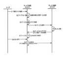
図8は、本発明に係わるサービス利用デバイス100でサービスA308を利用しサービス提供デバイス101のサービスA対応カウンタA403をアップ(UP(加算))するときに、失敗した場合のリカバリ(復旧)処理を示すシーケンス図である。 FIG. 8 shows a recovery process when the
ステップS10において、サービス利用デバイス100は、ユーザがサービス利用デバイス100のユーザインターフェース501上、有効化されたボタン502(図5参照)を押下するのを検知する。 In step S <b> 10, the
次に、ステップS11において、以下の処理が行なわれる。すなわち、サービス利用デバイス100は、サービスA308を実行し、サービスA対応カウンタA403へのネットワークアダプタ309を経由してサービス提供デバイス101のサービスA対応カウンタA403をアップ(UP(加算))する処理を行う。ここでは、サービス提供デバイス101で、何らかの不具合が発生し通信が遮断されており、サービスA対応カウンタA403のアップ(UP(加算))が失敗する。 Next, in step S11, the following processing is performed. That is, the
次に、ステップS12において、サービス利用デバイス100は、サービスA308のサービスA対応カウンタ型データA316を利用し汎用カウンタ314内に一時カウンタA315を作成する。 Next, in step S <b> 12, the
次に、ステップS13において、サービス利用デバイス100は、上記作成した一時カウンタA315のカウンタをアップ(UP(加算))する。 Next, in step S13, the
次に、ステップS14において、上記不具合が解消されている場合、サービス提供デバイス101は、サービスA401のサービス貸し出し記録406をチェックする。 Next, in step S <b> 14, when the above problem is solved, the
次に、ステップS15において、サービス提供デバイス101は、上記貸し出し記録のチェック結果を元にサービス利用デバイス100に対してサービスA308を利用したカウンタ情報を要求する。 Next, in step S15, the
次に、ステップS16において、サービス利用デバイス100は、上記要求を元にサービス提供デバイス101に対して一時カウンタA315に保持されたカウンタ情報を提供する。 Next, in step S16, the
次に、ステップS17において、サービス提供デバイス101は、上記カウンタ情報を元にサービスA対応カウンタA403の値を加算して更新する。 In step S17, the
次に、ステップS18において、サービス利用デバイス100は、一時カウンタA315を削除する。 Next, in step S18, the
次に、ステップS19において、サービス利用デバイス100は、ユーザが可搬デバイス103をサービス利用デバイス100から抜き取ることを検知する。 Next, in step S <b> 19, the
次に、ステップS20において、サービス利用デバイス100は、サービスA308とサービスA対応カウンタ型データA316を削除する。 Next, in step S <b> 20, the
次に、ステップS21において、サービス利用デバイス100は、サービスA308の利用が終了したことをサービス提供デバイス101に通知する。 Next, in step S <b> 21, the
次に、ステップS22において、サービス提供デバイス101は、サービスA401のサービス貸し出し記録406を削除する。 Next, in step S22, the
次に、ステップS23において、サービス利用デバイス100でワークフローを満たすサービスが全て削除された場合、ワークフローシステム300のUI制御部301が、ユーザインターフェース500上のボタンを無効化する(図5参照)。 Next, when all the services that satisfy the workflow are deleted in the
上記一連の処理により、ネットワーク上に存在する、サービス利用デバイスにてサービスが利用された回数をサービス提供元のデバイス内にカウンタデータとして集計し、通信障害等が起きたときに、カウンタ値をリカバリ(復旧)することが可能となる。 Through the above series of processing, the number of times the service is used on the service device on the network is counted as counter data in the device that provides the service, and the counter value is recovered when a communication failure occurs. (Recovery) can be performed.
上記の実施形態では、一例として、カウンタ値をリカバリ(復旧)するシステムについて説明したが、リカバリ(復旧)されるのは、カウンタ値に限らない。すなわち、上記の実施形態を、送信元デバイスと送信先デバイスとの間でやりとりされるアプリケーションに関連するあらゆるデータのリカバリ(復旧)に利用することができる。 In the above-described embodiment, a system for recovering (recovering) a counter value has been described as an example. However, what is recovered (recovered) is not limited to a counter value. That is, the above embodiment can be used for recovery of all data related to an application exchanged between a transmission source device and a transmission destination device.
本発明の目的は、前述した実施形態の機能を実現するソフトウェアのプログラムコードを記録したコンピュータで読取可能な記憶媒体を、システム或いは装置に供給することによっても達成される。そのシステム或いは装置のコンピュータ、またはCPU、MPUが記憶媒体に格納されたプログラムコードを読み出し実行することによって、本発明の目的が達成される。 The object of the present invention can also be achieved by supplying a computer-readable storage medium that records a program code of software that implements the functions of the above-described embodiments to a system or apparatus. The object of the present invention is achieved by the computer or CPU or MPU of the system or apparatus reading and executing the program code stored in the storage medium.
この場合、記憶媒体から読み出されたプログラムコード自体が前述した実施形態の機能を実現することになり、プログラムコード自体及びそのプログラムコードを記憶した記憶媒体も本発明に含まれる。 In this case, the program code itself read from the storage medium realizes the functions of the above-described embodiments, and the program code itself and the storage medium storing the program code are also included in the present invention.
プログラムコードを供給するための記憶媒体としては、例えば、フレキシブルディスク、ハードディスク、光ディスク、光磁気ディスク、CD−ROM、CD−R、磁気テープ、不揮発性のメモリカード、ROM等が用いられる。 As a storage medium for supplying the program code, for example, a flexible disk, a hard disk, an optical disk, a magneto-optical disk, a CD-ROM, a CD-R, a magnetic tape, a nonvolatile memory card, a ROM, or the like is used.
また、コンピュータが読み出したプログラムコードを実行することにより、前述した実施形態の機能が実現されても良い。また、コンピュータ上で稼動しているOS(基本システム或いはオペレーティングシステム)などがそのプログラムコードの指示に基づき実際の処理の一部又は全部を行い、その処理によって前述した実施形態の機能が実現されても良い。 Further, the functions of the above-described embodiments may be realized by executing the program code read by the computer. Further, the OS (basic system or operating system) running on the computer performs part or all of the actual processing based on the instruction of the program code, and the functions of the above-described embodiments are realized by the processing. Also good.
さらに、記憶媒体から読み出されたプログラムコードが、コンピュータに挿入された機能拡張ボードやコンピュータに接続された機能拡張ユニットに備わるメモリに書込まれて、前述した実施形態の機能が実現されても良い。その場合、その機能拡張ボードや機能拡張ユニットに備わるCPU等がそのプログラムコードの指示に基づき実際の処理の一部又は全部を行い、その処理によって前述した実施形態の機能が実現される。 Further, the program code read from the storage medium is written in a memory provided in a function expansion board inserted into the computer or a function expansion unit connected to the computer, so that the functions of the above-described embodiments are realized. good. In that case, a CPU or the like provided in the function expansion board or function expansion unit performs part or all of the actual processing based on an instruction of the program code, and the functions of the above-described embodiments are realized by the processing.
100 サービス利用デバイス
101 サービス提供デバイス
102 Network
103 可搬デバイス
200 コア部
201 CPU
202 ユーザインターフェース部
203 スキャナ部
204 プリンタ部
205 ネットワークインターフェース部
206 ファクシミリ部
207 記憶装置
208 拡張インターフェース部
209 ネットワーク
210 公衆回線
211 可搬デバイス
300 ワークフローシステム
301 UI制御部
302 ワークフローマネージャ
303 ワークフローサービス
304 サービス検索モジュール
305 ワークフロー定義ファイル
306 定義ファイル検索モジュール
307 ソフトウェアプラットホーム
308 サービスA
309 カウンタAへのネットワークアダプタ
310 サービス・・・
311 カウンタ・・・へのネットワークアダプタ
312 可搬デバイス内ファイルシステム
313 ワークフロー定義ファイル
314 汎用カウンタ
315 一時カウンタA
316 サービスA対応カウンタ型データA
317 一時カウンタ・・・
318 サービス・・・対応カウンタ型データ・・・
400 ソフトウェアプラットホーム
401 サービスA
402 カウンタ
403 サービス対応カウンタA
404 サービスA対応カウンタ型データA
405 カウンタAへのネットワークアダプタ
406 サービス貸し出し記録
500 ユーザインターフェース
501 ユーザインターフェース
502 ボタン
600 汎用カウンタ
601 カウンタ型データ
602 一時カウンタA100
103
202
309
316 Counter type data A for service A
317 Temporary counter
318 Service ・ ・ ・ Supported counter type data ・ ・ ・
400
402
404 Counter type data A for service A
405
Claims (5)
Translated fromJapanese前記送信元デバイスは、
前記送信先デバイスの要求に応じてアプリケーションを前記アプリケーションに関連したデータとともに前記送信先デバイスに送信する手段と、
前記送信した前記アプリケーションの貸し出し記録を記録する手段と、
前記アプリケーションが前記送信先デバイスで実行された回数を保持する手段と、
前記送信先デバイスの加算要求に応じて前記回数を加算する手段と、
該送信元デバイスに不具合が発生して該不具合が解消した場合に、前記貸し出し記録をチェックして前記貸し出し記録が残っている送信先デバイスに対して前記送信先デバイスで記録される前記アプリケーションが実行された回数を含むカウンタ情報を要求する手段と、
前記カウンタ情報の要求に応じて前記送信先デバイスから通知されるカウンタ情報を用いて前記回数を加算して更新する手段とを備え、
前記送信先デバイスは、
前記送信元デバイスから取得した前記アプリケーションを実行した回数を加算するよう前記送信元デバイスに加算要求する手段と、
前記加算要求が失敗した場合に、カウンタ情報を記録する一時カウンタを前記アプリケーションに関連したデータに基づいて作成する手段と、
前記加算要求が失敗した以降に前記アプリケーションが実行される回数を前記一時カウンタで加算してカウンタ情報を生成する手段と、
前記送信元デバイスからの前記カウンタ情報の要求に応じて、前記生成したカウンタ情報を通知する手段とを備えたことを特徴とするデバイスシステム。A device system including a source deviceand a destination device,
The source device is
Meansfor transmitting an application to thedestination device along with data associated with the application inresponse toa request of thedestination device ;
Means for recording a loan record of the transmitted application;
Means for holding the number of times the application has been executed on the destination device;
Means for adding the number of times in response to an addition request of the destination device;
When the problem occurs in the transmission source device and the problem is resolved, the application recorded in the transmission destination device is executed for the transmission destination device that checks the lending record and the lending record remains. Means for requesting counter information including the number of times
Means for adding and updating the number of times using counter information notified from the destination device in response to a request for the counter information,
The destination device is
Means for requesting the transmission source device to add the number of times the application acquired from the transmission source device has been executed;
Means for creating a temporary counter for recording counter information based on data associated with the application when the addition request fails;
Means for generating counter information by adding the number of times the application is executed after the addition request has failed with the temporary counter;
A device systemcomprising: meansfor notifying thegenerated counter information in response to a request for the counter information from the transmission source device .
前記送信元デバイスは、前記送信先デバイスから送信された前記アプリケーションの実行の終了の通知に基づいて、前記送信先デバイスに関する貸し出し記録を削除する手段をさらに備えたことを特徴とする請求項1に記載のデバイスシステム。2. The transmission source device according to claim 1, further comprising means for deleting a lending record related to the transmission destination device based on a notification of completion of execution of the application transmitted from the transmission destination device. The device system described.
前記送信元デバイスは、The source device is
前記送信先デバイスの要求に応じてアプリケーションを前記アプリケーションに関連したデータとともに前記送信先デバイスに送信するステップと、Transmitting an application to the destination device along with data associated with the application in response to a request of the destination device;
前記送信した前記アプリケーションの貸し出し記録を記録するステップと、Recording a loan record of the transmitted application;
前記アプリケーションが前記送信先デバイスで実行された回数を保持するステップと、Holding the number of times the application has been executed on the destination device;
前記送信先デバイスの加算要求に応じて前記回数を加算するステップと、Adding the number of times in response to an addition request of the destination device;
該送信元デバイスに不具合が発生して該不具合が解消した場合に、前記貸し出し記録をチェックして前記貸し出し記録が残っている送信先デバイスに対して前記送信先デバイスで記録される前記アプリケーションが実行された回数を含むカウンタ情報を要求するステップと、When the problem occurs in the transmission source device and the problem is resolved, the application recorded in the transmission destination device is executed for the transmission destination device that checks the lending record and the lending record remains. Requesting counter information including the number of times
前記カウンタ情報の要求に応じて前記送信先デバイスから通知されるカウンタ情報を用いて前記回数を加算して更新するステップとを実行し、Performing the step of adding and updating the number of times using the counter information notified from the destination device in response to the request for the counter information,
前記送信先デバイスは、The destination device is
前記送信元デバイスから取得した前記アプリケーションを実行した回数を加算するよう前記送信元デバイスに加算要求するステップと、Requesting the transmission source device to add the number of times the application acquired from the transmission source device is executed;
前記加算要求が失敗した場合に、カウンタ情報を記録する一時カウンタを前記アプリケーションに関連したデータに基づいて作成するステップと、Creating a temporary counter to record counter information based on data associated with the application if the addition request fails;
前記加算要求が失敗した以降に前記アプリケーションが実行される回数を前記一時カウンタで加算してカウンタ情報を生成するステップと、Generating counter information by adding the number of times the application is executed after the addition request fails with the temporary counter;
前記送信元デバイスからの前記カウンタ情報の要求に応じて、前記生成したカウンタ情報を通知するステップとを実行することを特徴とするデバイスシステムの制御方法。And a step of notifying the generated counter information in response to a request for the counter information from the transmission source device.
前記送信元デバイスは、前記送信先デバイスから送信された前記アプリケーションの実行の終了の通知に基づいて、前記送信先デバイスに関する貸し出し記録を削除するステップをさらに実行することを特徴とする請求項3に記載のデバイスシステムの制御方法。The said transmission source device further performs the step which deletes the lending record regarding the said transmission destination device based on the notification of the completion | finish of execution of the said application transmitted from the said transmission destination device. The device system control method described.
Priority Applications (2)
| Application Number | Priority Date | Filing Date | Title |
|---|---|---|---|
| JP2007231440AJP4441555B2 (en) | 2007-09-06 | 2007-09-06 | Device system, device system control method, and computer program |
| US12/204,142US8189222B2 (en) | 2007-09-06 | 2008-09-04 | Device system, source device, and transmission method |
Applications Claiming Priority (1)
| Application Number | Priority Date | Filing Date | Title |
|---|---|---|---|
| JP2007231440AJP4441555B2 (en) | 2007-09-06 | 2007-09-06 | Device system, device system control method, and computer program |
Publications (2)
| Publication Number | Publication Date |
|---|---|
| JP2009064234A JP2009064234A (en) | 2009-03-26 |
| JP4441555B2true JP4441555B2 (en) | 2010-03-31 |
Family
ID=40431522
Family Applications (1)
| Application Number | Title | Priority Date | Filing Date |
|---|---|---|---|
| JP2007231440AExpired - Fee RelatedJP4441555B2 (en) | 2007-09-06 | 2007-09-06 | Device system, device system control method, and computer program |
Country Status (2)
| Country | Link |
|---|---|
| US (1) | US8189222B2 (en) |
| JP (1) | JP4441555B2 (en) |
Families Citing this family (15)
| Publication number | Priority date | Publication date | Assignee | Title |
|---|---|---|---|---|
| US8402111B2 (en) | 2009-01-28 | 2013-03-19 | Headwater Partners I, Llc | Device assisted services install |
| US8391834B2 (en) | 2009-01-28 | 2013-03-05 | Headwater Partners I Llc | Security techniques for device assisted services |
| US8275830B2 (en) | 2009-01-28 | 2012-09-25 | Headwater Partners I Llc | Device assisted CDR creation, aggregation, mediation and billing |
| US8346225B2 (en) | 2009-01-28 | 2013-01-01 | Headwater Partners I, Llc | Quality of service for device assisted services |
| US8406748B2 (en) | 2009-01-28 | 2013-03-26 | Headwater Partners I Llc | Adaptive ambient services |
| US11985155B2 (en) | 2009-01-28 | 2024-05-14 | Headwater Research Llc | Communications device with secure data path processing agents |
| US9565707B2 (en) | 2009-01-28 | 2017-02-07 | Headwater Partners I Llc | Wireless end-user device with wireless data attribution to multiple personas |
| US12166596B2 (en) | 2009-01-28 | 2024-12-10 | Disney Enterprises, Inc. | Device-assisted services for protecting network capacity |
| US10326800B2 (en) | 2009-01-28 | 2019-06-18 | Headwater Research Llc | Wireless network service interfaces |
| US12389218B2 (en) | 2009-01-28 | 2025-08-12 | Headwater Research Llc | Service selection set publishing to device agent with on-device service selection |
| US10484858B2 (en) | 2009-01-28 | 2019-11-19 | Headwater Research Llc | Enhanced roaming services and converged carrier networks with device assisted services and a proxy |
| US10779177B2 (en)* | 2009-01-28 | 2020-09-15 | Headwater Research Llc | Device group partitions and settlement platform |
| EP2618251A4 (en) | 2010-09-13 | 2015-05-27 | Konica Minolta Business Tech | Accounting management system |
| JP5751809B2 (en)* | 2010-11-18 | 2015-07-22 | キヤノン株式会社 | Image forming apparatus, management method, and program |
| US9050846B2 (en)* | 2013-03-28 | 2015-06-09 | Hewlett-Packard Development Company, L.P. | Finisher output destinations |
Family Cites Families (23)
| Publication number | Priority date | Publication date | Assignee | Title |
|---|---|---|---|---|
| JPH04150340A (en) | 1990-10-11 | 1992-05-22 | Mitsubishi Electric Corp | Charging data transfer system in packet exchange system |
| US20020091560A1 (en)* | 2000-12-20 | 2002-07-11 | Atsuhito Suzuki | Work flow management method and system and processing program thereof |
| JP2002189841A (en)* | 2000-12-20 | 2002-07-05 | Hitachi Ltd | Workflow management method and system and recording medium storing the processing program |
| US6958824B2 (en)* | 2001-01-31 | 2005-10-25 | Hewlett-Packard Development Company, L.P. | System and method for accessing and using a commercial print service |
| US6909519B2 (en)* | 2001-11-08 | 2005-06-21 | Hewlett-Packard Development Company, L.P. | Method and system for printer suggested upgrades |
| US6676310B2 (en)* | 2001-11-15 | 2004-01-13 | Hewlett-Packard Development Company, L.P. | Check writing system and method |
| JP2004042530A (en) | 2002-07-15 | 2004-02-12 | Konica Minolta Holdings Inc | Image forming system, image forming device and information providing device |
| JP4217455B2 (en)* | 2002-10-15 | 2009-02-04 | キヤノン株式会社 | Peripheral device, information processing method, and control program |
| JP4847045B2 (en)* | 2004-07-15 | 2011-12-28 | キヤノン株式会社 | Image reading apparatus, image reading method, and image reading system |
| US20060092467A1 (en)* | 2004-09-01 | 2006-05-04 | Dumitrescu Tiberiu A | Print job workflow system |
| US7869079B2 (en)* | 2004-09-20 | 2011-01-11 | Electronics For Imaging, Inc. | Methods and apparatus for print job submission |
| US7623255B2 (en)* | 2004-10-22 | 2009-11-24 | Hewlett-Packard Development Company, L.P. | Printing device |
| JP2006211587A (en)* | 2005-01-31 | 2006-08-10 | Ricoh Co Ltd | Image processing apparatus, log management method, and log management system |
| JP4757503B2 (en) | 2005-02-02 | 2011-08-24 | Necインフロンティア株式会社 | License authentication system and method using detachable device having MAC address |
| JP4413152B2 (en)* | 2005-02-18 | 2010-02-10 | シャープ株式会社 | Image forming apparatus, program, recording medium, and data transmission method |
| JP4345721B2 (en)* | 2005-07-14 | 2009-10-14 | コニカミノルタビジネステクノロジーズ株式会社 | Management system |
| US7822270B2 (en)* | 2005-08-31 | 2010-10-26 | Microsoft Corporation | Multimedia color management system |
| US20070279676A1 (en)* | 2006-06-06 | 2007-12-06 | Kabushiki Kaisha Toshiba | System and method for pipelined dataflow document processing |
| JP4270269B2 (en)* | 2006-11-30 | 2009-05-27 | ブラザー工業株式会社 | Communication system, printing apparatus, user terminal apparatus, and program |
| JP5239170B2 (en)* | 2007-02-28 | 2013-07-17 | 富士ゼロックス株式会社 | Image processing system and program |
| US20080247004A1 (en)* | 2007-04-03 | 2008-10-09 | Michael Yeung | System and method for workflow control of scanned document input |
| JP4375434B2 (en)* | 2007-05-18 | 2009-12-02 | コニカミノルタビジネステクノロジーズ株式会社 | Workflow execution system and execution method, image processing apparatus, and work substitute processing program |
| US20090067008A1 (en)* | 2007-09-06 | 2009-03-12 | Kodimer Marianne L | System and method for transportable software operation of document processing devices |
- 2007
- 2007-09-06JPJP2007231440Apatent/JP4441555B2/ennot_activeExpired - Fee Related
- 2008
- 2008-09-04USUS12/204,142patent/US8189222B2/ennot_activeExpired - Fee Related
Also Published As
| Publication number | Publication date |
|---|---|
| US20090066999A1 (en) | 2009-03-12 |
| JP2009064234A (en) | 2009-03-26 |
| US8189222B2 (en) | 2012-05-29 |
Similar Documents
| Publication | Publication Date | Title |
|---|---|---|
| JP4441555B2 (en) | Device system, device system control method, and computer program | |
| JP5241345B2 (en) | Job processing apparatus, job log management method of the job processing apparatus, and job history management system | |
| US20120030329A1 (en) | Information processing apparatus, linked scenario preparation method for information processing apparatus, program, and storage medium | |
| JP2013088950A (en) | Printing system and printing method | |
| JP2008084298A (en) | System, method and program for assessing copyright royalty based on content to be copied | |
| JP5169756B2 (en) | Job log processing apparatus and program | |
| US20100293491A1 (en) | Information Processing Apparatus, System, And Program | |
| JP7585793B2 (en) | Image forming device | |
| JP5381059B2 (en) | Device, log recording control method, and program | |
| US20150248653A1 (en) | Image processing apparatus, non-transitory computer readable medium, and method | |
| JP2021101319A (en) | Information processing device and information processing program | |
| JP2007312225A (en) | Data processing apparatus, data processing method and data processing program executed by the apparatus | |
| JP2015108857A (en) | System, control method thereof, information processing apparatus, control method thereof and program | |
| JP4866620B2 (en) | Document processing apparatus and image forming apparatus | |
| JP2016045690A (en) | Management system and method for controlling management system | |
| JP2006092192A (en) | Failure recovery support system, failure recovery support device, management device, and failure recovery support method | |
| JP2010021702A (en) | Information processing apparatus | |
| JP6107084B2 (en) | Information processing apparatus, update program, update control system | |
| JP2008152428A (en) | Management device, management method, storage medium, program | |
| JP2007102416A (en) | Electronic equipment | |
| JP5263438B2 (en) | Charge calculation system | |
| JP2015011612A (en) | Information processor and information processing program | |
| JP5412827B2 (en) | Document management apparatus, document management program, and document management system | |
| JP5636738B2 (en) | Charge calculation system | |
| JP2003233770A (en) | Electronic delivery support device, checking device and program |
Legal Events
| Date | Code | Title | Description |
|---|---|---|---|
| A977 | Report on retrieval | Free format text:JAPANESE INTERMEDIATE CODE: A971007 Effective date:20090630 | |
| A131 | Notification of reasons for refusal | Free format text:JAPANESE INTERMEDIATE CODE: A131 Effective date:20090703 | |
| A521 | Request for written amendment filed | Free format text:JAPANESE INTERMEDIATE CODE: A523 Effective date:20090901 | |
| TRDD | Decision of grant or rejection written | ||
| A01 | Written decision to grant a patent or to grant a registration (utility model) | Free format text:JAPANESE INTERMEDIATE CODE: A01 Effective date:20091211 | |
| A01 | Written decision to grant a patent or to grant a registration (utility model) | Free format text:JAPANESE INTERMEDIATE CODE: A01 | |
| A61 | First payment of annual fees (during grant procedure) | Free format text:JAPANESE INTERMEDIATE CODE: A61 Effective date:20100108 | |
| FPAY | Renewal fee payment (event date is renewal date of database) | Free format text:PAYMENT UNTIL: 20130115 Year of fee payment:3 | |
| R150 | Certificate of patent or registration of utility model | Free format text:JAPANESE INTERMEDIATE CODE: R150 | |
| FPAY | Renewal fee payment (event date is renewal date of database) | Free format text:PAYMENT UNTIL: 20140115 Year of fee payment:4 | |
| LAPS | Cancellation because of no payment of annual fees |