JP4439575B2 - Cooker - Google Patents
CookerDownload PDFInfo
- Publication number
- JP4439575B2 JP4439575B2JP2008222780AJP2008222780AJP4439575B2JP 4439575 B2JP4439575 B2JP 4439575B2JP 2008222780 AJP2008222780 AJP 2008222780AJP 2008222780 AJP2008222780 AJP 2008222780AJP 4439575 B2JP4439575 B2JP 4439575B2
- Authority
- JP
- Japan
- Prior art keywords
- duct
- dilution
- exhaust
- air
- heating chamber
- Prior art date
- Legal status (The legal status is an assumption and is not a legal conclusion. Google has not performed a legal analysis and makes no representation as to the accuracy of the status listed.)
- Expired - Fee Related
Links
Images


Classifications
- F—MECHANICAL ENGINEERING; LIGHTING; HEATING; WEAPONS; BLASTING
- F24—HEATING; RANGES; VENTILATING
- F24C—DOMESTIC STOVES OR RANGES ; DETAILS OF DOMESTIC STOVES OR RANGES, OF GENERAL APPLICATION
- F24C15/00—Details
- F24C15/32—Arrangements of ducts for hot gases, e.g. in or around baking ovens
- F24C15/322—Arrangements of ducts for hot gases, e.g. in or around baking ovens with forced circulation
- F24C15/327—Arrangements of ducts for hot gases, e.g. in or around baking ovens with forced circulation with air moisturising
- F—MECHANICAL ENGINEERING; LIGHTING; HEATING; WEAPONS; BLASTING
- F24—HEATING; RANGES; VENTILATING
- F24C—DOMESTIC STOVES OR RANGES ; DETAILS OF DOMESTIC STOVES OR RANGES, OF GENERAL APPLICATION
- F24C15/00—Details
- F24C15/20—Removing cooking fumes
- F24C15/2042—Devices for removing cooking fumes structurally associated with a cooking range e.g. downdraft
- H—ELECTRICITY
- H05—ELECTRIC TECHNIQUES NOT OTHERWISE PROVIDED FOR
- H05B—ELECTRIC HEATING; ELECTRIC LIGHT SOURCES NOT OTHERWISE PROVIDED FOR; CIRCUIT ARRANGEMENTS FOR ELECTRIC LIGHT SOURCES, IN GENERAL
- H05B6/00—Heating by electric, magnetic or electromagnetic fields
- H05B6/64—Heating using microwaves
- H05B6/647—Aspects related to microwave heating combined with other heating techniques
- H05B6/6473—Aspects related to microwave heating combined with other heating techniques combined with convection heating
- H05B6/6479—Aspects related to microwave heating combined with other heating techniques combined with convection heating using steam
Landscapes
- Engineering & Computer Science (AREA)
- Chemical & Material Sciences (AREA)
- Combustion & Propulsion (AREA)
- Mechanical Engineering (AREA)
- General Engineering & Computer Science (AREA)
- Physics & Mathematics (AREA)
- Electromagnetism (AREA)
- Electric Ovens (AREA)
- Baking, Grill, Roasting (AREA)
- Fuel Cell (AREA)
Description
Translated fromJapanese本発明は加熱室の内部で食材を加熱するオーブン形式の加熱調理器に関する。 The present invention relates to an oven-type cooking device that heats ingredients inside a heating chamber.
高周波、電熱、熱風、水蒸気などにより加熱室内に入れられた食材を加熱するオーブン形式の加熱調理器は、日常生活に欠かせないものになっている。この種加熱調理器には、加熱に伴い食材から発生する油煙や水蒸気、あるいは食材加熱に用いた水蒸気を強制的に排気する仕組みを備えているものがある。その例を特許文献1に見ることができる。 An oven-type cooking device that heats food contained in a heating chamber using high frequency, electric heat, hot air, steam, or the like is indispensable for daily life. Some types of this type of cooking device are provided with a mechanism for forcibly exhausting oily smoke and water vapor generated from foods with heating, or water vapor used for heating foods. An example of this can be seen in US Pat.
加熱室からの排気は高温であるばかりでなく、大量の水蒸気や油煙を含む。そのため、排気口の直近上方や側方に壁や家具、他の電気機器等が迫っている場合には、それらが湿ったり、油煙で汚れたりすることがあった。この問題に対処するため、特許文献1記載の加熱調理器では、排気を外気と混合して希釈することにより温度を下げ、湿りや汚れを与える要因を軽減してから排気するようにしている。
特許文献1記載の加熱調理器の排気希釈装置は、排気系統にダンパを含む複雑な構成になっている。本発明は、加熱調理器の排気希釈装置を、ダンパを用いない比較的簡素な構成で、既存設計の加熱調理器に組み込みやすいものとすることを目的とする。また、何らかの事故で吹出口が閉塞されるようなことがあったとしても、排気続行が可能な排気希釈装置を提供することを目的とする。 The exhaust gas dilution device of the heating cooker described in
上記目的を達成するために本発明は、加熱室に排気希釈装置が設けられ、前記排気希釈装置は、希釈ファンから送り込まれた空気を第1エジェクタを介して吹出口より吹き出す吹出ダクトと、前記吹出ダクトの中で、前記第1エジェクタが吸引効果をもたらす位置に設けられた吸引口に一端が接続され、他端は吸気口となった希釈ダクトと、前記加熱室の側壁に設けられた排気口に一端が接続され、他端は前記希釈ダクトの中で前記吸引口と吸気口の間の位置に第2エジェクタを介して接続される排気ダクトと、を含む加熱調理器であることを特徴としている。 In order to achieve the above object, the present invention provides an exhaust dilution device in a heating chamber, and the exhaust dilution device blows out air sent from a dilution fan from a blow outlet through a first ejector, In the blowout duct, one end is connected to a suction port provided at a position where the first ejector provides a suction effect, and the other end serves as an intake port, and an exhaust provided on the side wall of the heating chamber. One end is connected to the mouth, and the other end is a heating cooker including an exhaust duct connected via a second ejector to a position between the suction port and the intake port in the dilution duct. It is said.
この構成によると、加熱室から排気を吸い出し、それを外気で希釈してから排出するシステムを、ダンパを用いることなく実現できる。基本的要素が希釈ファンとダクト群、及びダクト内に設けられたエジェクタだけなので、構成が簡単で製作容易であり、既存設計の加熱調理器に組み込みやすい。 According to this configuration, it is possible to realize a system that sucks exhaust gas from the heating chamber, dilutes it with outside air, and discharges it without using a damper. Since the basic elements are only the dilution fan, the duct group, and the ejector provided in the duct, the configuration is simple and easy to manufacture, and it can be easily incorporated into a heating cooker of an existing design.
また本発明は、上記構成の加熱調理器において、前記第2エジェクタのノズル部は、互いに間隔を置き、ほぼ平行して前記排気ダクトから前記希釈ダクトの中に突き出す吸引口側導風板と吸気口側導風板を含み、前記吸引口側導風板の方が前記吸気口側導風板よりも希釈ダクト内への突き出し量が大であることを特徴としている。 According to the present invention, in the cooking device configured as described above, the nozzle portion of the second ejector is spaced apart from each other and is substantially parallel to the suction duct side air guide plate and the intake air that protrude from the exhaust duct into the dilution duct. An inlet side wind guide plate is included, and the suction port side wind guide plate has a larger amount of protrusion into the dilution duct than the intake port side wind guide plate.
この構成によると、吹出ダクトの吹出口が何らかの事故で閉塞されたとき、希釈ファンからの気流は吸引口から希釈ダクトに流れ込み、吸気口から出ようとする。このため希釈ダクトの中には通常と逆に吸引口から吸気口へと向かう気流が生じるが、その気流が第2エジェクタを通じて排気ダクトに入ることは吸引口側導風板によって阻止され、逆に、その気流による静圧低下で排気ダクトから気体が吸い出される。従って排気ダクトからの排気はそのまま続行される。 According to this configuration, when the outlet of the outlet duct is blocked due to some accident, the airflow from the dilution fan flows into the dilution duct from the suction port and tries to exit from the inlet. For this reason, in the dilution duct, an air flow from the suction port to the intake port is generated in the opposite direction, but the air flow is prevented from entering the exhaust duct through the second ejector by the suction port side air guide plate. The gas is sucked out of the exhaust duct due to a decrease in static pressure due to the airflow. Therefore, the exhaust from the exhaust duct is continued as it is.
また本発明は、上記構成の加熱調理器において、前記第2エジェクタのノズル部は、前記排気ダクトとの連通部より前記吸引口の方へ傾斜していることを特徴としている。 Moreover, the present invention is characterized in that, in the cooking device configured as described above, the nozzle portion of the second ejector is inclined toward the suction port from the communicating portion with the exhaust duct.
この構成によると、排気ダクトから第2エジェクタを通じて排出される排気は吸引口に向かって流れ、希釈ダクト中の外気の流れにスムーズに混じって吹出ダクトに流入する。 According to this configuration, the exhaust discharged from the exhaust duct through the second ejector flows toward the suction port, and smoothly flows into the flow of outside air in the dilution duct and flows into the blowout duct.
本発明によると、加熱調理器の排気希釈装置を、構成簡単且つ製作容易で、既存設計の加熱調理器に組み込みやすいものとすることができる。また、何らかの事故で吹出口が閉塞されたとしても排気続行可能なものとすることができる。 According to the present invention, the exhaust gas dilution device for a cooking device can be easily configured and easily manufactured, and can be easily incorporated into a cooking device of an existing design. Further, even if the air outlet is blocked due to some accident, the exhaust can be continued.
以下本発明の実施形態を図に基づき説明する。図1は加熱調理器を側面から見た概略断面図、図2は図1と同様の概略断面図であって断面位置をずらしたもの、図3は加熱調理器を正面から見た概略断面図、図4は図3と同様の概略断面図であって断面位置をずらしたもの、図5は加熱調理器を上から見た概略断面図、図6は蒸気発生装置の拡大断面図、図7は希釈ダクトと排気ダクトの拡大断面図、図8は図7と異なる動作状態を示す希釈ダクトと排気ダクトの拡大断面図、図9はブロック構成図である。 Embodiments of the present invention will be described below with reference to the drawings. 1 is a schematic cross-sectional view of the heating cooker as viewed from the side, FIG. 2 is a schematic cross-sectional view similar to that of FIG. 1 with the cross-sectional position shifted, and FIG. 3 is a schematic cross-sectional view of the heating cooker as viewed from the front. 4 is a schematic cross-sectional view similar to FIG. 3 with the cross-sectional position shifted, FIG. 5 is a schematic cross-sectional view of the heating cooker from above, FIG. 6 is an enlarged cross-sectional view of the steam generator, FIG. Is an enlarged cross-sectional view of the dilution duct and the exhaust duct, FIG. 8 is an enlarged cross-sectional view of the dilution duct and the exhaust duct showing an operation state different from FIG. 7, and FIG. 9 is a block diagram.
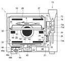
加熱調理器1は直方体形状のキャビネット10を備える。キャビネット10の内部には同じく直方体形状の加熱室20が設けられる。加熱室20はキャビネット10の正面側が開口部となっている。キャビネット10の正面には加熱室20の開口部を開閉する扉11が設けられる。扉11は下部を支点として垂直面内で回動するものであり、上部のハンドル12を握って手前に引くことにより、図1に示す垂直な全閉位置から水平な全開位置へと90°姿勢変換させることができる。扉11には高周波漏洩防止対策が施され、また蒸気洩れを防ぐガスケットが取り付けられるが、それらは周知技術なので説明は割愛する。 The
調理中の食材から発生した蒸気や、調理に用いる蒸気が扉11の内面に結露することがある。結露水が滴り落ちて加熱調理器1の設置場所を濡らさないように、扉11の下には露受け13が配置されている。 Steam generated from ingredients during cooking or steam used for cooking may condense on the inner surface of the
加熱室20には、正面から見て右側の側壁(以後「右側壁」と称する)の外側に給気ダクト21が設けられる。給気ダクト21は水平方向に延び、その一端にはキャビネット10内部の空気を取り込む給気ファン22が配置されている。給気ファン22はプロペラファン(軸流ファン)である。給気ダクト21の他端は加熱室20に空気を送り込む給気口23に接続する。給気口23は加熱室20の右側壁に形成された複数の小孔の集合よりなる。 The
さらに加熱室20には、右側壁に排気ダクト24が設けられる。排気ダクト24の一端は加熱室20の内部から空気を出す排気口25に接続する。排気ダクト24は後で説明する排気希釈装置の一環をなすものである。排気口25は加熱室20の右側壁に形成された複数の小孔の集合よりなる。 Further, the
排気ダクト24は、排気口25への接続箇所から垂直に立ち上がる。排気ダクト24の内部には、排気口25から空気を迎える位置に湿度センサ26が配置されている。他方加熱室20の天井部には、サーミスタからなる温度センサ27が配置されている。 The
食材Fを加熱室20内で支持するのは、周縁に脚部を有する食材支持網30と、それを載置する食材トレイ31である。加熱室20の内部には、挿入された食材トレイ31を所定高さに支持するトレイ受けが設けられる。本実施形態では、加熱室20の両側壁に、食材トレイ31の左辺と右辺を係合させてそれを水平に支持するトレイ受けが形成されている。 The food F is supported in the
図3に示すように、トレイ受けは上下2段に設けられる。上段トレイ受け32と下段トレイ受け33を構成するのは、それぞれ加熱室20の側壁から突き出すうね状の突部である。 As shown in FIG. 3, the tray receiver is provided in two upper and lower stages. What constitutes the
加熱調理器1は、高周波による加熱、熱風による加熱、水蒸気による加熱、及びそれらを混合した加熱が可能となっている。続いて、各加熱手段の構成を説明する。 The
加熱室20の底部とキャビネット10の底部の間の空間には、マグネトロン40と、マグネトロン40が生成した高周波を加熱室20に供給する導波管41が配置される。導波管41は加熱室20の底部の下に広がるアンテナ収納キャビティ42に接続する。アンテナ収納キャビティ42はガラスやセラミックなどの誘電体からなる仕切板43で加熱室20と隔てられている。仕切板43は、加熱室20にとっては底板となり、アンテナ収納キャビティ42にとっては天井板となるものである。 In the space between the bottom of the
アンテナ収納キャビティ42には受信アンテナ部と放射アンテナ部を備えたアンテナ44が配置される。アンテナ44はアンテナモータ45の軸の上端に取り付けられており、アンテナモータ45の回転制御で連続回転または揺動(周期的反転)し、加熱室20内における高周波の分布をコントロールする。 An
加熱室20の底部とキャビネット10の底部の間の空間には電装部品収容部46が設けられ、その中の制御基板に高周波駆動電源47(図9参照)が装着される。高周波駆動電源47とマグネトロン40は高周波加熱時発熱部品、すなわち高周波発振の際かなりの発熱を伴う部品なので、これらを強制空冷する冷却ファン48がキャビネット10の底部の上に設置される。冷却ファン48は、ファンケーシング48aと、竪軸の冷却ファンモータ48bと、冷却ファンモータ48bの軸の上端に固定されたシロッコファン48cにより構成される。冷却ファンモータ48bを駆動してシロッコファン48cを回転させると、キャビネット10の底部に形成された吸気口49(これも複数の小孔の集合よりなる)から外部の空気が吸い込まれ、その空気はファンケーシング48aの吐出口より水平方向に勢いよく吐出されて高周波加熱時発熱部品を空冷する。 An
熱風による加熱は、加熱室20の奥の壁の外側に設けられたコンベクションヒータユニット50によって実現される。コンベクションヒータユニット50を構成するのは、加熱室20の奥の壁の外面に固定された皿形の断熱ファンケーシング51と、断熱ファンケーシング51と加熱室20の奥の壁で囲まれた空間に配置されるコンベクションファン52と、コンベクションファン52を回転させるコンベクションモータ53と、コンベクションファン52の外周を囲む環状のコンベクションヒータ54である。 Heating with hot air is realized by a
コンベクションファン52は遠心ファンであって、加熱室20の奥の壁の中央に形成された吸気口55から加熱室20の内部の空気を吸い込み、それを外周方向に吐出して、吸気口55を囲む形で加熱室20の奥の壁の計6箇所に形成された噴気口56より加熱室20に噴出させる。コンベクションヒータ54に通電しておけば、コンベクションファン52から吐出される空気が加熱され、噴気口56から熱風が噴き出すことになる。なお吸気口55も噴気口56も、複数の小孔の集合よりなる。 The
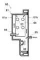
水蒸気による加熱を実現するのは、加熱室20の右側壁の外側に設置された蒸気発生装置60である。蒸気発生装置60は飽和水蒸気または過熱水蒸気を発生することが可能であり、以下その構造を主に図6を参照しつつ説明する。 It is the
蒸気発生装置60は、正面から見て左右方向に偏平となったハウジング61を有し、ハウジング61の内部には、下部に蒸気発生ヒータ62、上部に蒸気昇温ヒータ63が設けられている。蒸気発生ヒータ62と蒸気昇温ヒータ63はいずれもシーズヒータからなり、右側面から見たとき、すなわち図1及び図2の視点では、蒸気発生ヒータ62は馬蹄形を描き、蒸気昇温ヒータ63は長円形のループを描く。蒸気昇温ヒータ63の長円形ループは図1において紙面奥行き方向に重なる連続二重ループとなっている。 The
ハウジング61はいずれもダイキャスト成型品である本体61aと蓋61bを合わせて形成されるものであり、蒸気発生ヒータ62は本体61aに鋳込まれている。本体61aの壁面の中で、蒸気発生ヒータ62を鋳込んだ部分は蓋61bの方に引っ込み、加熱室20の右側壁との間に間隔が生じている。このため、蒸気発生ヒータ62の発生する熱は加熱室20の右側壁に伝わりにくく、本来の目的である蒸気発生に有効利用される。 The
蒸気昇温ヒータ63は、ハウジング61の内部において、上面が開口した箱状の仕切部材64で囲まれる。仕切部材64はハウジング61よりも耐熱性の高い金属やセラミックで形成される。仕切部材64の内面には黒色耐熱塗料が塗施される。これは、蒸気昇温ヒータ63の輻射熱を極力仕切部材64で吸収し、ハウジング61の昇温を抑制するためである。 The steam
ハウジング61の蓋61bには、蒸気発生ヒータ62より少し高いレベルに給水口65が形成される。給水口65には給水ポンプ66(図3、図5参照)の送水管66aが接続される。給水ポンプ66の吸水管66bは給水タンク67の底部に接続される。給水ポンプ66と給水タンク67はキャビネット10の右側壁と加熱室20の右側壁の間の空間に配置されるものであり、給水タンク67はキャビネット10の正面側から出し入れできるようになっている。 A
ハウジング61の本体61aの側壁には、給水口65より少し高い位置に、ハウジング61の内外に突き出す水平な蒸気噴出口68が形成される。蒸気噴出口68の一端は仕切部材64に形成された貫通孔を通じて仕切部材64の内部に頭を出し、蒸気噴出口68の他端は加熱室20の右側壁に形成された貫通孔を通じて加熱室20の内部に頭を出す。仕切部材64が金属製である場合、前述の黒色耐熱塗装は仕切部材64とハウジング61の間の異種金属同士の接触による電食を防止するのに役立つ。蒸気噴出口68は、キャビネット10の正面側から背面側へ一列に並ぶ形で計4個形成されていて、食材支持網30と食材トレイ31の間隙に飽和水蒸気または過熱水蒸気を噴出する。 On the side wall of the
加熱室の右側壁の外側に排気希釈装置70が設置される。排気希釈装置70の主たる構成要素は、排気ダクト24の他、希釈ファン71、吹出ダクト72、希釈ダクト73、吹出ダクト71の内部に形成される第1エジェクタ74、及び排気ダクト24と希釈ダクト73の間に形成される第2エジェクタ75である。 An
希釈ファン71は、ケーシング71aと、ケーシング71a内に配置されたシロッコファン71bと、シロッコファン71bを回転させる希釈ファンモータ71c(図9参照)により構成される。ケーシング71aからは送風ダクト71dが水平に延び出し、吹出ダクト72の内部に入り込む。送風ダクト71dの末端は上向きに直角に折れ曲がり、第1エジェクタ74のノズル部74aとなる。 The
吹出ダクト72は上端がキャビネット10の天面の上に突き出す。この部分に、加熱調理器1の正面斜め上方を指向する吹出口72aが形成される。吹出口72aには気流を所定方向に向けるルーバ72bが設けられている。吹出ダクト72の一部はくびれており、このくびれた部分が、ノズル部74aと共に第1エジェクタ74を構成するスロート部74bとなっている。 The upper end of the
吹出ダクト72には、第1エジェクタ74よりも下の部分に吸引口72cが形成されている。ここは第1エジェクタ74が吸引効果をもたらす箇所である。吸引口72cは希釈ダクト73に連通する。 A
吹出ダクト72の底部には排水チューブ72dが接続される。吹出ダクト72の内面には排気に含まれる水蒸気が結露する。また吹出口72aから吹出ダクト72に水が入ることもある。排水チューブ72dはこれらの水を図示しない排水路や排水タンクに流し出すためのものである。 A
希釈ダクト73は、図1の視点では吹出ダクト72の奥に存在するものであり、水平に延び、一方の端は閉じ、他方の端は開いている。閉じた方の端は吹出ダクト72の吸引口72cに接続する。開いた方の端はキャビネット10の外側に露出し、その開口部を吸気口73aとしている。 The
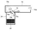
排気ダクト24は希釈ダクト73の下面に接続する。排気ダクト24と希釈ダクト73の境界壁に第2エジェクタ75が形成される。第2エジェクタ75が形成されるのは希釈ダクト73の中で吸引口72cと吸気口73aの間の位置である。 The
図7に示すように、第2エジェクタ75のノズル部75aは、互いに間隔を置き、ほぼ平行して排気ダクト24から希釈ダクト73の中に突き出す吸引口側導風板75bと吸気口側導風板74cを含む。吸引口側導風板75bの方が吸気口側導風板75cよりも希釈ダクト73内への突き出し量が大であり、両者の突き出し量の間には差hが存在する。ノズル部75aは排気ダクト24との連通部より吸引口72cの方へ傾斜している。 As shown in FIG. 7, the
加熱調理器1の制御要素を図9に示す。全体の制御を司るのは制御装置80である。制御装置80には、給気ファン22、アンテナモータ45、高周波電源部47、冷却ファンモータ48b、コンベクションモータ53、コンベクションヒータ54、蒸気発生ヒータ62、蒸気昇温ヒータ63、給水ポンプ66、希釈ファンモータ71c、湿度センサ26、温度センサ27といった既述の要素の他、操作部14、表示部15、水位センサ60a、タンク水位センサ67a、及び扉開閉センサ11aが接続されている。操作部14は扉11の表面に設けられるものであり、押釦やダイヤルなどの操作手段を含む。表示部15も扉11の表面に設けられるものであり、液晶表示パネルなどの表示手段を含む。水位センサ60aは蒸気発生装置60に設けられてその内部の水位を測定し、タンク水位センサ67aは給水タンク67に設けられてその内部の水位を測定する。扉開閉センサ11aは扉11に対して設けられ、扉11が開いているか閉じているかを判定する。 The control elements of the
高周波による加熱を行う場合は、高周波駆動電源47、給気ファン22、冷却ファン48、及び希釈ファン71をそれぞれONにする。するとマグネトロン40が発振して高周波が発生し、発生した高周波は導波管41を通じてアンテナ収納キャビティ42に入る。アンテナ収納キャビティ42に入った高周波はアンテナ44の受信アンテナ部に受信された後、放射アンテナ部より仕切板43を通じて加熱室20に放射される。そして加熱室20内の食材Fを加熱する。給気ファン22が加熱室20に新鮮な空気を供給することにより、食材Fから発生する水蒸気を含んだ加熱室20内の空気は排気口25より排気ダクト24に押し出され、希釈ファン71の作用で希釈された後、吹出ダクト72に吸い込まれて吹出口72aから機外に排出される。 When heating by high frequency, the high frequency
熱風による加熱を行う場合は、給気ファン22がOFF、希釈ファン71がONの状態で、コンベクションモータ53とコンベクションヒータ54をONにする。コンベクションモータ53によって回転せしめられるコンベクションファン52が給気口55から加熱室20の内部の空気を吸い込み、それを外周方向に吐出する。コンベクションファン52から吐出された空気はコンベクションヒータ54で加熱されて熱風となり、噴気口56より加熱室20に噴き出して加熱室20内の食材Fを加熱する。この場合も希釈ファン71の作動により、食材Fから発生する油煙、臭気、水蒸気等は排気口25から排気ダクト24に吸い込まれ、希釈された後、吹出口72aから機外に排出される。 When heating with hot air is performed, the
水蒸気による加熱を行う場合は、給気ファン22がOFF、希釈ファン71がONの状態で、蒸気発生装置60のハウジング61に所定水位まで水を入れ、ヒータをONにする。蒸気発生ヒータ62のみONにした場合は、発生した水蒸気はハウジング61の内面と仕切部材64の間の隙間を通って仕切部材64の中に入り、蒸気噴出口68より加熱室20に噴き出す。この時噴き出すのは飽和水蒸気である。 In the case of heating with water vapor, with the
蒸気昇温ヒータ63もONにすると、仕切部材64の中に入った飽和水蒸気が加熱され、過熱水蒸気となって加熱室20に噴き出す。 When the steam
飽和水蒸気または過熱水蒸気を加熱室20に噴射すると、加熱室20内の余分な水蒸気は排気口25から排気ダクト24に排出される。この水蒸気は希釈ファン71の作用で希釈され、低温化して安全となり、さらに相対湿度が下がって周囲の壁で結露しにくい状態になってから、排気として吹出口72aより機外に排出される。 When saturated steam or superheated steam is injected into the
高周波加熱、熱風加熱、及び蒸気加熱は単独で遂行することもできるし、それらを二つないし三つ同時に遂行することもできる。冷却時等のように、加熱室20内の空気を強制的に入れ換える場合は給気ファン22と希釈ファン71を運転する。 High frequency heating, hot air heating, and steam heating can be performed independently, or two or three of them can be performed simultaneously. When the air in the
希釈ファン71を運転すると、それに吸い込まれたキャビネット10内の空気がノズル部74aから上向きに噴出し、第1エジェクタ74を高速で通過する。この高速気流は静圧を低下させ、周囲の空気を巻き込みつつ吹出口72aへと向かうので、吹出ダクト72の第1エジェクタ74よりも下の部分に吸引効果が生じ、巻き込まれた分の空気を補う分の空気が希釈ダクト73から吸引口72cを通じて吸い込まれる。 When the
吸引口72cに生じる吸引力で、希釈ダクト73には吸気口73aより多量の外気が吸い込まれる。さらに、図7に示すように、吸引口72cで生じる吸引力の一部により、第2エジェクタ75を通じて排気ダクト24内の気体が希釈ダクト73に吸い出される。この気体は吸気口73aから吸い込まれる外気と混じり合って希釈される。このため、排気ダクト24内の気体が高温で、水蒸気や油煙を多く含むものであったとしても、それは外気で希釈され、周囲に湿りや汚れを与える要因が軽減された形で吹出口72aより機外に排出されることになる。 Due to the suction force generated at the
第2エジェクタ75のノズル部75aが排気ダクト24との連通部より吸引口72cの方へ傾斜していることにより、給気ファン22がONの場合、排気ダクト24から第2エジェクタ75を通じて排出される排気は吸引口72cに向かって流れ、希釈ダクト73中の外気の流れにスムーズに混じって吹出ダクト72に流入する。 When the
何らかの事故で吹出口72aが閉塞されると、希釈ファン71によりノズル部74aから噴出する空気は行き場を失い、吸引口72cから希釈ダクト73に噴き出す。このため希釈ダクト73内には、図8に示すように、吸引口72cから吸気口73aへと向かう、通常とは逆の気流が発生し、その気流は吸気口73aから排出される。 When the
吸引口72cから吸気口73aに向かう気流は、吸引口側導風板75bが希釈ダクト73の中に突き出していることにより、第2エジェクタ75には入り込まない。そして吸気口側導風板75cの突き出しが吸引口側導風板75bよりもhだけ小さいことから、第2エジェクタ75には吸引口72cから吸気口73aに向かう気流による静圧低下により吸い出し効果が生じ、排気ダクト24内の気体が吸い出される。これにより、排気ダクト24を通じての排気はそのまま続行されるから、希釈ファン71からの送風が排気口25から加熱室20内に逆流することはない。そのため、電装部品収容部46やマグネトロン40が存在するキャビネット10内の空間に、給気口23や板金の接合部等を通じ加熱室20内の水蒸気や油煙が漏れ出す危険がない。 The airflow from the
以上、本発明の実施形態につき説明したが、本発明の範囲はこれに限定されるものではなく、発明の主旨を逸脱しない範囲で種々の変更を加えて実施することができる。 Although the embodiments of the present invention have been described above, the scope of the present invention is not limited to these embodiments, and various modifications can be made without departing from the spirit of the invention.
本発明は加熱室の内部で食材を加熱するオーブン形式の加熱調理器に広く利用可能である。 The present invention can be widely used in an oven-type cooking device that heats ingredients inside a heating chamber.
1 加熱調理器
10 キャビネット
20 加熱室
24 排気ダクト
25 排気口
30 食材支持網
31 食材トレイ
F 食材
40 マグネトロン
47 高周波駆動電源
48 冷却ファン
50 コンベクションヒータユニット
60 蒸気発生装置
70 排気希釈装置
71 希釈ファン
72 吹出ダクト
72a 吹出口
72c 吸引口
73 希釈ダクト
73a 吸気口
74 第1エジェクタ
75 第2エジェクタ
75a ノズル部
75b 吸引口側導風板
74c 吸気口側導風板
80 制御装置DESCRIPTION OF
Claims (3)
Translated fromJapanese前記排気希釈装置は、
希釈ファンから送り込まれた空気を第1エジェクタを介して吹出口より吹き出す吹出ダクトと、
前記吹出ダクトの中で、前記第1エジェクタが吸引効果をもたらす位置に設けられた吸引口に一端が接続され、他端は吸気口となった希釈ダクトと、
前記加熱室の側壁に設けられた排気口に一端が接続され、他端は前記希釈ダクトの中で前記吸引口と吸気口の間の位置に第2エジェクタを介して接続される排気ダクトと、
を含むことを特徴とする加熱調理器。An exhaust dilution device is provided at the exhaust port of the heating chamber,
The exhaust dilution device includes:
A blowout duct for blowing out air sent from the dilution fan from the blowout opening via the first ejector;
A dilution duct in which one end is connected to a suction port provided at a position where the first ejector provides a suction effect in the blowout duct, and the other end is an intake port;
One end is connected to an exhaust port provided on the side wall of the heating chamber, and the other end is connected to a position between the suction port and the intake port in the dilution duct via a second ejector,
A heating cooker comprising:
導風板の方が前記吸気口側導風板よりも希釈ダクト内への突き出し量が大であることを特徴とする請求項1に記載の加熱調理器。The nozzle part of the second ejector includes a suction port side wind guide plate and an intake port side wind guide plate that are spaced apart from each other and project substantially parallel to the exhaust duct from the exhaust duct. The cooking device according to claim 1, wherein the air plate has a larger amount of protrusion into the dilution duct than the air intake side air guide plate.
Priority Applications (6)
| Application Number | Priority Date | Filing Date | Title |
|---|---|---|---|
| JP2008222780AJP4439575B2 (en) | 2008-08-29 | 2008-08-29 | Cooker |
| PCT/JP2009/064830WO2010024273A1 (en) | 2008-08-29 | 2009-08-26 | Cooking device |
| CN2009801336816ACN102132102B (en) | 2008-08-29 | 2009-08-26 | heating cooker |
| MYPI20110560MY152407A (en) | 2008-08-29 | 2009-08-26 | Cooking device |
| US13/059,486US20110132346A1 (en) | 2008-08-29 | 2009-08-26 | Cooking device |
| EP09809924AEP2322859A1 (en) | 2008-08-29 | 2009-08-26 | Cooking device |
Applications Claiming Priority (1)
| Application Number | Priority Date | Filing Date | Title |
|---|---|---|---|
| JP2008222780AJP4439575B2 (en) | 2008-08-29 | 2008-08-29 | Cooker |
Publications (2)
| Publication Number | Publication Date |
|---|---|
| JP2010054178A JP2010054178A (en) | 2010-03-11 |
| JP4439575B2true JP4439575B2 (en) | 2010-03-24 |
Family
ID=41721440
Family Applications (1)
| Application Number | Title | Priority Date | Filing Date |
|---|---|---|---|
| JP2008222780AExpired - Fee RelatedJP4439575B2 (en) | 2008-08-29 | 2008-08-29 | Cooker |
Country Status (6)
| Country | Link |
|---|---|
| US (1) | US20110132346A1 (en) |
| EP (1) | EP2322859A1 (en) |
| JP (1) | JP4439575B2 (en) |
| CN (1) | CN102132102B (en) |
| MY (1) | MY152407A (en) |
| WO (1) | WO2010024273A1 (en) |
Families Citing this family (17)
| Publication number | Priority date | Publication date | Assignee | Title |
|---|---|---|---|---|
| JP4843100B1 (en)* | 2010-08-31 | 2011-12-21 | シャープ株式会社 | Cooker |
| EP2445311B1 (en)* | 2011-12-28 | 2017-05-31 | V-Zug AG | Combination cooking device |
| EP2859275A1 (en)* | 2012-06-06 | 2015-04-15 | Arçelik Anonim Sirketi | An oven with increased ventilating effectiveness |
| EP2999999A4 (en) | 2013-05-23 | 2017-03-29 | Duke Manufacturing Co. | Food preparation apparatus and methods |
| US10918112B2 (en) | 2013-05-23 | 2021-02-16 | Duke Manufacturing Co. | Dough preparation apparatus and methods |
| US9357787B2 (en) | 2013-06-27 | 2016-06-07 | Middleby Marshall Holdings Llc | Forced moisture evacuation for rapid baking |
| US12222107B2 (en)* | 2015-06-01 | 2025-02-11 | June Life, Llc | Thermal management system and method for a connected oven |
| WO2016196669A1 (en)* | 2015-06-01 | 2016-12-08 | June Life, Inc. | Thermal management system and method for a connected oven |
| JP6655460B2 (en)* | 2016-04-28 | 2020-02-26 | 日立グローバルライフソリューションズ株式会社 | Cooker |
| DE102016215650A1 (en)* | 2016-08-19 | 2018-02-22 | BSH Hausgeräte GmbH | Haushaltsgargerät |
| TR201712881A2 (en)* | 2017-08-28 | 2019-03-21 | Arcelik As | AN OVEN WITH A STEAM EVACUATION SYSTEM |
| CN107898300A (en)* | 2017-11-02 | 2018-04-13 | 广东美的厨房电器制造有限公司 | Cooking apparatus |
| CN110881867A (en)* | 2018-09-10 | 2020-03-17 | 江门市顶厨电器有限公司 | Steam food box and steam oven/steam box with same |
| JP7149501B2 (en)* | 2019-01-10 | 2022-10-07 | パナソニックIpマネジメント株式会社 | heating cooker |
| US11339975B2 (en) | 2020-02-17 | 2022-05-24 | Bsh Home Appliances Corporation | Exhaust gas mixing flue for gas appliance |
| JP7659454B2 (en) | 2021-06-24 | 2025-04-09 | シャープ株式会社 | Cooking equipment |
| CN114431729A (en)* | 2022-02-28 | 2022-05-06 | 海信家电集团股份有限公司 | An oven and its control method |
Family Cites Families (9)
| Publication number | Priority date | Publication date | Assignee | Title |
|---|---|---|---|---|
| JP3688604B2 (en)* | 2001-07-10 | 2005-08-31 | 株式会社マルゼン | Electric pottery |
| KR100848161B1 (en)* | 2002-11-29 | 2008-07-23 | 삼성전자주식회사 | Cooker with air purifier |
| JP4115889B2 (en)* | 2003-06-13 | 2008-07-09 | 松下電器産業株式会社 | Built-in cooker |
| JP3710460B2 (en)* | 2003-07-31 | 2005-10-26 | シャープ株式会社 | Steam cooker |
| JP4398814B2 (en)* | 2004-07-16 | 2010-01-13 | シャープ株式会社 | Steam cooker |
| JP4542485B2 (en)* | 2004-12-14 | 2010-09-15 | 日本碍子株式会社 | Alumina member and manufacturing method thereof |
| JP2006284013A (en)* | 2005-03-31 | 2006-10-19 | Sharp Corp | Cooker |
| KR100650266B1 (en)* | 2005-12-19 | 2006-11-27 | 엘지전자 주식회사 | Compound cooker system |
| JP4311688B2 (en)* | 2006-11-02 | 2009-08-12 | シャープ株式会社 | Exhaust steam diluting apparatus and cooking device equipped with the same |
- 2008
- 2008-08-29JPJP2008222780Apatent/JP4439575B2/ennot_activeExpired - Fee Related
- 2009
- 2009-08-26EPEP09809924Apatent/EP2322859A1/ennot_activeWithdrawn
- 2009-08-26WOPCT/JP2009/064830patent/WO2010024273A1/enactiveApplication Filing
- 2009-08-26CNCN2009801336816Apatent/CN102132102B/ennot_activeExpired - Fee Related
- 2009-08-26MYMYPI20110560patent/MY152407A/enunknown
- 2009-08-26USUS13/059,486patent/US20110132346A1/ennot_activeAbandoned
Also Published As
| Publication number | Publication date |
|---|---|
| EP2322859A1 (en) | 2011-05-18 |
| MY152407A (en) | 2014-09-30 |
| WO2010024273A1 (en) | 2010-03-04 |
| US20110132346A1 (en) | 2011-06-09 |
| CN102132102B (en) | 2013-10-23 |
| JP2010054178A (en) | 2010-03-11 |
| CN102132102A (en) | 2011-07-20 |
Similar Documents
| Publication | Publication Date | Title |
|---|---|---|
| JP4439575B2 (en) | Cooker | |
| JP6128341B2 (en) | Cooker | |
| JP4311688B2 (en) | Exhaust steam diluting apparatus and cooking device equipped with the same | |
| CN1902445B (en) | hot cooking equipment | |
| US7241976B2 (en) | Steam cooker | |
| JP2008032304A (en) | Heating cooker and steam generating device for heating cooker | |
| JP3737094B2 (en) | Steam cooker | |
| CN100507359C (en) | Steam generating device and steam cooking appliance provided with steam generating device | |
| JP4334201B2 (en) | Cooker | |
| JP2010054097A (en) | Heating cooker | |
| JP5084897B2 (en) | Cooker | |
| JP4029099B2 (en) | Cooker | |
| JP2011007493A (en) | Heating cooker and steam generating device for heating cooker | |
| JP6209733B2 (en) | Cooker | |
| JP4680141B2 (en) | Cooker | |
| JP5694090B2 (en) | Cooker | |
| JP6156725B2 (en) | Cooker | |
| JP5996001B2 (en) | Cooker | |
| JP4229860B2 (en) | Steam cooker | |
| JP2005195250A (en) | Steam cooker | |
| JP4229861B2 (en) | Steam cooker | |
| JP2011007492A (en) | Heating cooker | |
| JP2019035513A (en) | Cooker | |
| JP2010048475A (en) | Cooker | |
| JP2007187443A (en) | Cooker |
Legal Events
| Date | Code | Title | Description |
|---|---|---|---|
| TRDD | Decision of grant or rejection written | ||
| A01 | Written decision to grant a patent or to grant a registration (utility model) | Free format text:JAPANESE INTERMEDIATE CODE: A01 Effective date:20091208 | |
| A01 | Written decision to grant a patent or to grant a registration (utility model) | Free format text:JAPANESE INTERMEDIATE CODE: A01 | |
| A61 | First payment of annual fees (during grant procedure) | Free format text:JAPANESE INTERMEDIATE CODE: A61 Effective date:20100105 | |
| FPAY | Renewal fee payment (event date is renewal date of database) | Free format text:PAYMENT UNTIL: 20130115 Year of fee payment:3 | |
| R150 | Certificate of patent or registration of utility model | Ref document number:4439575 Country of ref document:JP Free format text:JAPANESE INTERMEDIATE CODE: R150 Free format text:JAPANESE INTERMEDIATE CODE: R150 | |
| FPAY | Renewal fee payment (event date is renewal date of database) | Free format text:PAYMENT UNTIL: 20130115 Year of fee payment:3 | |
| LAPS | Cancellation because of no payment of annual fees | ||
| S531 | Written request for registration of change of domicile | Free format text:JAPANESE INTERMEDIATE CODE: R313531 | |
| R350 | Written notification of registration of transfer | Free format text:JAPANESE INTERMEDIATE CODE: R350 |