JP4438406B2 - Stabilizer control device - Google Patents
Stabilizer control deviceDownload PDFInfo
- Publication number
- JP4438406B2 JP4438406B2JP2003426396AJP2003426396AJP4438406B2JP 4438406 B2JP4438406 B2JP 4438406B2JP 2003426396 AJP2003426396 AJP 2003426396AJP 2003426396 AJP2003426396 AJP 2003426396AJP 4438406 B2JP4438406 B2JP 4438406B2
- Authority
- JP
- Japan
- Prior art keywords
- stabilizer
- electric motor
- vehicle
- motor
- relay
- Prior art date
- Legal status (The legal status is an assumption and is not a legal conclusion. Google has not performed a legal analysis and makes no representation as to the accuracy of the status listed.)
- Expired - Fee Related
Links
Images


Classifications
- B—PERFORMING OPERATIONS; TRANSPORTING
- B60—VEHICLES IN GENERAL
- B60G—VEHICLE SUSPENSION ARRANGEMENTS
- B60G17/00—Resilient suspensions having means for adjusting the spring or vibration-damper characteristics, for regulating the distance between a supporting surface and a sprung part of vehicle or for locking suspension during use to meet varying vehicular or surface conditions, e.g. due to speed or load
- B60G17/015—Resilient suspensions having means for adjusting the spring or vibration-damper characteristics, for regulating the distance between a supporting surface and a sprung part of vehicle or for locking suspension during use to meet varying vehicular or surface conditions, e.g. due to speed or load the regulating means comprising electric or electronic elements
- B60G17/018—Resilient suspensions having means for adjusting the spring or vibration-damper characteristics, for regulating the distance between a supporting surface and a sprung part of vehicle or for locking suspension during use to meet varying vehicular or surface conditions, e.g. due to speed or load the regulating means comprising electric or electronic elements characterised by the use of a specific signal treatment or control method
- B60G17/0185—Resilient suspensions having means for adjusting the spring or vibration-damper characteristics, for regulating the distance between a supporting surface and a sprung part of vehicle or for locking suspension during use to meet varying vehicular or surface conditions, e.g. due to speed or load the regulating means comprising electric or electronic elements characterised by the use of a specific signal treatment or control method for failure detection
- B—PERFORMING OPERATIONS; TRANSPORTING
- B60—VEHICLES IN GENERAL
- B60G—VEHICLE SUSPENSION ARRANGEMENTS
- B60G17/00—Resilient suspensions having means for adjusting the spring or vibration-damper characteristics, for regulating the distance between a supporting surface and a sprung part of vehicle or for locking suspension during use to meet varying vehicular or surface conditions, e.g. due to speed or load
- B60G17/015—Resilient suspensions having means for adjusting the spring or vibration-damper characteristics, for regulating the distance between a supporting surface and a sprung part of vehicle or for locking suspension during use to meet varying vehicular or surface conditions, e.g. due to speed or load the regulating means comprising electric or electronic elements
- B60G17/016—Resilient suspensions having means for adjusting the spring or vibration-damper characteristics, for regulating the distance between a supporting surface and a sprung part of vehicle or for locking suspension during use to meet varying vehicular or surface conditions, e.g. due to speed or load the regulating means comprising electric or electronic elements characterised by their responsiveness, when the vehicle is travelling, to specific motion, a specific condition, or driver input
- B60G17/0162—Resilient suspensions having means for adjusting the spring or vibration-damper characteristics, for regulating the distance between a supporting surface and a sprung part of vehicle or for locking suspension during use to meet varying vehicular or surface conditions, e.g. due to speed or load the regulating means comprising electric or electronic elements characterised by their responsiveness, when the vehicle is travelling, to specific motion, a specific condition, or driver input mainly during a motion involving steering operation, e.g. cornering, overtaking
- B—PERFORMING OPERATIONS; TRANSPORTING
- B60—VEHICLES IN GENERAL
- B60G—VEHICLE SUSPENSION ARRANGEMENTS
- B60G21/00—Interconnection systems for two or more resiliently-suspended wheels, e.g. for stabilising a vehicle body with respect to acceleration, deceleration or centrifugal forces
- B60G21/02—Interconnection systems for two or more resiliently-suspended wheels, e.g. for stabilising a vehicle body with respect to acceleration, deceleration or centrifugal forces permanently interconnected
- B60G21/04—Interconnection systems for two or more resiliently-suspended wheels, e.g. for stabilising a vehicle body with respect to acceleration, deceleration or centrifugal forces permanently interconnected mechanically
- B60G21/05—Interconnection systems for two or more resiliently-suspended wheels, e.g. for stabilising a vehicle body with respect to acceleration, deceleration or centrifugal forces permanently interconnected mechanically between wheels on the same axle but on different sides of the vehicle, i.e. the left and right wheel suspensions being interconnected
- B60G21/055—Stabiliser bars
- B60G21/0551—Mounting means therefor
- B60G21/0553—Mounting means therefor adjustable
- B60G21/0555—Mounting means therefor adjustable including an actuator inducing vehicle roll
Landscapes
- Engineering & Computer Science (AREA)
- Mechanical Engineering (AREA)
- Vehicle Body Suspensions (AREA)
- Protection Of Generators And Motors (AREA)
Description
Translated fromJapanese本発明は、車両のスタビライザ制御装置に関し、特に、左右車輪間に配設するスタビライザのねじり剛性を電気モータによって可変制御するスタビライザ制御装置に係る。The present invention relates to a stabilizer control apparatus for a vehicle, in particular, according to the stabilizer control apparatus for variably controlling a torsional rigidityof a stabilizer disposed between a right wheel and a left wheel by an electric motor.
一般的に、車両のスタビライザ制御装置は、車両の旋回走行中にスタビライザバーの作用により適切なロールモーメントを外部から付与し、車体のロール運動を低減または抑制するように構成されている。この機能を実現するため、例えば特許文献1には、スタビライザバーを二分割し、その半部分間に電気機械式旋回アクチュエータを設けた車両の横揺れ安定化装置が提案されている。 In general, a stabilizer control device for a vehicle is configured to reduce or suppress a roll motion of a vehicle body by applying an appropriate roll moment from the outside by an action of a stabilizer bar while the vehicle is turning. In order to realize this function, for example,
上記特許文献1に開示された車両の横揺れ安定化装置においては、調節範囲外においても受動的車両に比較して横揺れをさらに低減できるという可能性を提供できるように、スタビライザ半部分の反対方向旋回変位をロックするためのロック手段が設けられている。そして、ロックするために電磁式開放ブレーキまたは電磁式閉止ブレーキを好適に使用することとしている。電磁式開放ブレーキを用いた場合においては、装置が故障したとき、適切な手段により、直進走行における車両ボディーの傾斜姿勢を回避するために、前車軸及び後車軸における調節アクチュエータがそれぞれその中立位置のみにロック可能であることが保証される。そのため、相互にロックされたスタビライザ半部分は受動的トーション・バーのように働く構成とされている。 In the roll stabilization device for a vehicle disclosed in the above-mentioned
然し乍ら、上記特許文献1の横揺れ安定化装置の構成においては、ロックを行なうために電磁式ブレーキ等の機械的な手段を電動機(モータ)と減速歯車装置との間に設けることが必要となり、アクチュエータの大型化が不可避となる。また、このアクチュエータはスタビライザバーを車体側において保持しなければならず、スタビライザバーの端部をサスペンションメンバに固定する必要があり、車両に搭載する上で制約があるため、アクチュエータの大型化は搭載性上、極めて不利となる。 However, in the configuration of the roll stabilizing device of
そこで、本発明は、スタビライザバーのねじり剛性を抑制するためのアクチュエータが大型化することなく、電力が供給されなくなった場合やスタビライザ制御装置が故障した場合にも、好適なロール特性を維持し得るスタビライザ制御装置を提供することを課題とする。 Therefore, the present invention can maintain suitable roll characteristics even when power is not supplied or the stabilizer control device fails without increasing the size of the actuator for suppressing the torsional rigidity of the stabilizer bar. It is an object to provide a stabilizer control device.
上記の課題を解決するため、本発明は、請求項1に記載のように、車両の左右車輪間に配設される一対のスタビライザバーの間に配置し、電気モータによって駆動するアクチュエータと、前記車両の旋回状態に応じて前記電気モータの出力を制御して前記スタビライザのねじり剛性を制御する制御手段とを備えたスタビライザ制御装置において、前記制御手段と前記電気モータとを接続するコネクタと、前記電気モータを構成するコイルに対し並列に配置され、非通電時には短絡回路を形成するノーマルクローズ型の少なくとも一つのモータリレーを備えたものとし、該モータリレーは前記コネクタに対し前記電気モータ側に配置し、前記電気モータに電力が供給されなくなった場合には、前記モータリレーを短絡させるように構成したものである。In order to solve the above problems, the present invention provides, as described in
また、本発明は、請求項2に記載のように、車両の左右車輪間に配設される一対のスタビライザバーの間に配置し、電気モータによって駆動するアクチュエータと、前記車両の旋回状態に応じて前記電気モータの出力を制御して前記スタビライザのねじり剛性を制御する制御手段とを備えたスタビライザ制御装置において、前記制御手段と前記電気モータとを接続するコネクタと、前記電気モータを構成するコイルに対し並列に配置され、非通電時には短絡回路を形成するノーマルクローズ型の少なくとも一つのモータリレーと、前記スタビライザ制御装置の故障状態を判定する故障判定手段とを備えたものとし、前記モータリレーは前記コネクタに対し前記電気モータ側に配置し、前記故障判定手段にて前記スタビライザ制御装置が故障と判定した場合には、前記モータリレーを短絡させるように構成してもよい。According to a second aspect of the present invention, the actuator is disposed between a pair of stabilizer bars disposed between the left and right wheels of the vehicle and is driven by an electric motor according to the turning state of the vehicle. And a control unit for controllingthe torsional rigidity of the stabilizer by controlling the output of theelectric motor, a connector for connecting the control unit and the electric motor, anda coilconstituting the electric motorAnd at least onenormally closed type motor relaythat forms a short circuit when not energized, and a failure determination means that determines a failure state of the stabilizer control device, themotor relay is the connector to be arranged on the electric motor side, the stabilizer control apparatus bysaid failure determining means failure and If was boss may also be configured to short-circuit the motor relay.
前記請求項1又は2に記載のスタビライザ制御装置において、請求項3に記載のように、前記電気モータに電力が供給されなくなった場合に、前記制御手段が、前記車両に対する所望の車体ロール角変化に応じて、前記モータリレーの短絡時間を制御するように構成することができる。In the stabilizer control apparatus according to
而して、請求項1及び2に記載のスタビライザ制御装置によれば、アクチュエータが大型化することなく、電気モータに電力が供給されなくなった場合や、スタビライザ制御装置が故障と判定された場合には、モータリレーを短絡させることにより、好適なロール特性を維持することができる。 Thus, according to the stabilizer control device according to
上記のスタビライザ制御装置において、請求項3に記載のように構成すれば、電気モータに電力が供給されなくなった場合には、モータリレーの短絡時間を適宜制御することにより、所望の車体ロール角変化を付与することができる。In the stabilizer controldevice, configured according to claim3,when the power is not supplied to the electric motor, by appropriately controlling the short-circuit time of the motor relay, the desired vehicle body roll angle variation Can be granted.
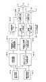
以下、本発明の望ましい実施形態を説明する。本発明の一実施形態に係るスタビライザ制御装置を備えた車両の全体構成を図1に示すように、車体(図示せず)にロール方向の運動が入力された場合に、ねじりばねとして作用する前輪側スタビライザSBfと後輪側スタビライザSBrが配設される。これら前輪側スタビライザSBf及び後輪側スタビライザSBrは、車体のロール運動である車体ロール角を抑制するために、各々のねじり剛性がスタビライザアクチュエータFT及びRTによって可変制御されるように構成されている。尚、これらスタビライザアクチュエータFT及びRTは電子制御装置ECU内のスタビライザ制御ユニットECU1によって制御される。 Hereinafter, preferred embodiments of the present invention will be described. As shown in FIG. 1, the entire configuration of a vehicle including a stabilizer control device according to an embodiment of the present invention is a front wheel that acts as a torsion spring when motion in the roll direction is input to a vehicle body (not shown). A side stabilizer SBf and a rear wheel side stabilizer SBr are provided. The front wheel side stabilizer SBf and the rear wheel side stabilizer SBr are configured such that their torsional rigidity is variably controlled by the stabilizer actuators FT and RT in order to suppress the vehicle body roll angle that is the roll motion of the vehicle body. The stabilizer actuators FT and RT are controlled by a stabilizer control unit ECU1 in the electronic control unit ECU.
図1に示すように各車輪WHxxには車輪速度センサWSxxが配設され(添字xxは各車輪を意味し、frは右側前輪、fl左側前輪、rrは右側後輪、rlは左側後輪を示す)、これらが電子制御装置ECUに接続されており、各車輪の回転速度、即ち車輪速度に比例するパルス数のパルス信号が電子制御装置ECUに入力されるように構成されている。更に、ステアリングホイールSWの操舵角(ハンドル角)δfを検出する操舵角センサSA、車両の前後加速度Gxを検出する前後加速度センサXG、車両の横加速度Gyを検出する横加速度センサYG、車両のヨーレイトYrを検出するヨーレイトセンサYR等が電子制御装置ECUに接続されている。 As shown in FIG. 1, each wheel WHxx is provided with a wheel speed sensor WSxx (subscript xx means each wheel, fr is a right front wheel, fl left front wheel, rr is a right rear wheel, and rl is a left rear wheel. These are connected to the electronic control unit ECU, and the rotation speed of each wheel, that is, a pulse signal having a pulse number proportional to the wheel speed is input to the electronic control unit ECU. Further, a steering angle sensor SA for detecting the steering angle (handle angle) δf of the steering wheel SW, a longitudinal acceleration sensor XG for detecting the longitudinal acceleration Gx of the vehicle, a lateral acceleration sensor YG for detecting the lateral acceleration Gy of the vehicle, and a yaw rate of the vehicle. A yaw rate sensor YR and the like for detecting Yr are connected to the electronic control unit ECU.
尚、電子制御装置ECU内には、スタビライザ制御ユニットECU1のほか、ブレーキ制御ユニットECU2、操舵制御ユニットECU3等が構成されており、これらの制御ユニットECU1乃至3は夫々、通信用のCPU、ROM及びRAMを備えた通信ユニットを介して通信バスに接続されている。而して、各制御システムに必要な情報を他の制御システムから送信することができる。 In addition to the stabilizer control unit ECU1, the electronic control unit ECU includes a brake control unit ECU2, a steering control unit ECU3, and the like. These control units ECU1 to ECU3 include a communication CPU, ROM, and It is connected to a communication bus via a communication unit having a RAM. Thus, information necessary for each control system can be transmitted from another control system.
図2は、スタビライザアクチュエータFTの具体的構成例(RTも同様の構成)を示すもので、前輪側スタビライザSBfは左右のスタビライザバーSBfr及びSBflに二分割されており、夫々の一端が左右の車輪に接続され、他端の一方側が減速機RDを介して電気モータMのロータRO、その他方側が電気モータMのステータSRに接続されている。尚、スタビライザバーSBfr及びSBflは保持手段HLfr及びHLflにより車体に保持される。而して、電気モータMが通電されると、二分割のスタビライザバーSBfr及びSBflの夫々に対しねじり力が生じ、みかけのねじりばね特性が変更されるので、車体のロール剛性が制御されることになる。尚、スタビライザアクチュエータは、図15を参照して後述する構成としてもよい。 FIG. 2 shows a specific configuration example of the stabilizer actuator FT (RT is the same configuration), where the front wheel side stabilizer SBf is divided into two left and right stabilizer bars SBfr and SBfl, and one end of each of the left and right wheels. The other end is connected to the rotor RO of the electric motor M via the speed reducer RD, and the other side is connected to the stator SR of the electric motor M. The stabilizer bars SBfr and SBfl are held on the vehicle body by holding means HLfr and HLfl. Thus, when the electric motor M is energized, a torsional force is generated for each of the two divided stabilizer bars SBfr and SBfl, and the apparent torsion spring characteristics are changed, so that the roll rigidity of the vehicle body is controlled. become. The stabilizer actuator may be configured as will be described later with reference to FIG.
上記の前輪側スタビライザSBfのスタビライザアクチュエータFTを構成する電気モータMは、スタビライザ制御ユニットECU1によって駆動制御される。本実施形態のスタビライザ制御ユニットECU1は図3に示すように構成されており、電気モータMに対しモータ駆動回路MCから供給される駆動電流が、コントローラCTによって制御される。このときモータ駆動回路MCから供給される駆動電流が電流検出部ISによって検出され、回転角検出手段RSによって検出された電気モータMの回転角信号と共に、コントローラCTにフィードバックされる。リレー駆動回路RC及びモータ駆動回路MCは電源PWに接続される。 The electric motor M constituting the stabilizer actuator FT of the front wheel side stabilizer SBf is driven and controlled by the stabilizer control unit ECU1. The stabilizer control unit ECU1 of the present embodiment is configured as shown in FIG. 3, and the drive current supplied from the motor drive circuit MC to the electric motor M is controlled by the controller CT. At this time, the drive current supplied from the motor drive circuit MC is detected by the current detector IS and fed back to the controller CT together with the rotation angle signal of the electric motor M detected by the rotation angle detection means RS. Relay drive circuit RC and motor drive circuit MC are connected to power supply PW.
そして、車両運動状態量、及び運転者のハンドル角δfを含む信号に基づき、コントローラCTによって、ロール抑制制御、モータサーボ制御、故障判定が行われ、その結果に応じて、リレー駆動回路RC及びモータ駆動回路MCが制御され、モータリレーRY及び電気モータMが制御されるが、これらについては後述する。更に、装置に故障が発生した場合には、モータリレーRYにより、電気モータMの端子間が短絡される。これにより、電気モータMに発生する逆起電力を利用して電気モータMに制動トルクを発生させることができ、この結果、車体ロール角の急激な変化が抑制される。 The controller CT performs roll suppression control, motor servo control, and failure determination based on a signal including the vehicle motion state quantity and the driver's steering wheel angle δf, and according to the result, the relay drive circuit RC and the motor The drive circuit MC is controlled and the motor relay RY and the electric motor M are controlled, which will be described later. Further, when a failure occurs in the apparatus, the terminals of the electric motor M are short-circuited by the motor relay RY. Thereby, the braking torque can be generated in the electric motor M using the back electromotive force generated in the electric motor M, and as a result, a sudden change in the vehicle body roll angle is suppressed.
モータ駆動回路MC及び電気モータMは図4に示すように構成されており、3相の電気モータMの端子間には、各端子間を短絡し得るリレーRLY1、RLY2及びRLY3が、夫々、電気モータMのコイルL1、L2及びL3に並列に接続されている。図4では、電気モータMにおけるU相、V相、W相の各相を短絡し得るリレーの配置構成となっているが、3相のうち、何れか2相間で短絡させれば全ての相間で短絡したことになるため、三つのリレーのうち一つを省略することが可能である。また、3相間のうち何れか一つの相間で短絡状態が形成できれば、制動トルクが得られるため、モータリレーは少なくとも一つあればその機能を発揮することができる。但し、系としての冗長性を求めるならば、全相間にモータリレーを配置する構成が望ましい。尚、本実施形態の電気モータMは3相からなるブラシレスモータが用いられるが、これに限定されるものではなく、他の相数を有するモータにも応用可能であり、ブラシモータに応用することも可能である。 The motor drive circuit MC and the electric motor M are configured as shown in FIG. 4, and relays RLY1, RLY2, and RLY3 that can short-circuit the terminals are electrically connected between the terminals of the three-phase electric motor M, respectively. The coils M1, L2 and L3 of the motor M are connected in parallel. In FIG. 4, the relay is configured to be able to short-circuit each of the U-phase, V-phase, and W-phase in the electric motor M, but if any two of the three phases are short-circuited, all the phases Therefore, one of the three relays can be omitted. Further, if a short circuit state can be formed between any one of the three phases, a braking torque can be obtained, so that at least one motor relay can exhibit its function. However, if redundancy as a system is required, a configuration in which motor relays are arranged between all phases is desirable. The electric motor M of this embodiment is a three-phase brushless motor. However, the electric motor M is not limited to this, and can be applied to motors having other numbers of phases. Is also possible.
コントローラCTによる故障判定演算を含む故障判定手段の判定結果に基づき、装置(例えばスタビライザアクチュエータFT)が故障と判定された場合には、リレーRLY1、RLY2及びRLY3の回路が短絡される。これらのリレーRLY1、RLY2及びRLY3は非通電時に短絡状態となるノーマルクローズ型のリレーであるため、リレー駆動電流がオフとされると、電気モータMのコイルL1、L2及びL3には短絡した回路が形成されるので、それまで電気モータMの回転によって発生していた逆起電力による電流が、短絡されたリレー回路を流れることとなる。即ち、電気モータMのコイルL1、L2及びL3の夫々の両端電圧は電位差がない状態となり、電気モータMは停止するように動くが、このとき短絡回路には電気モータMの回転によって発生していた逆起電力による電流が流れる。 If the device (for example, the stabilizer actuator FT) is determined to be defective based on the determination result of the failure determination means including the failure determination calculation by the controller CT, the circuits of the relays RLY1, RLY2, and RLY3 are short-circuited. Since these relays RLY1, RLY2, and RLY3 are normally closed relays that are short-circuited when not energized, a circuit that is short-circuited to the coils L1, L2, and L3 of the electric motor M when the relay drive current is turned off. Therefore, the current due to the counter electromotive force that has been generated by the rotation of the electric motor M until then flows through the short-circuited relay circuit. That is, the voltage across each of the coils L1, L2, and L3 of the electric motor M is in a state where there is no potential difference, and the electric motor M moves to stop, but at this time, the short circuit is generated by the rotation of the electric motor M. Current caused by back electromotive force flows.
この逆起電力による電流は、コイルL1、L2及びL3を流れ、これらの回路に存在する内部抵抗によって消費されて徐々に電流値は減少する。この働きが電気モータMの制動トルクとなって、あたかもブレーキ力を付与したように作用し、電気モータMに対する外力(車体慣性力)による回転は阻止される。つまり、モータリレーRY(リレーRLY1、RLY2及びRLY3を総称)によって短絡回路が形成され、その結果発生する逆起電力により電気モータMに制動トルクが付与され、車体ロール角変化が抑制されることになる。更に、このときの車体ロール角変化が好適な特性となるように電気モータMに対し所望の減速を行なうことができ、その場合には、上述したリレーRLY1、RLY2及びRLY3の短絡回路の開閉を、好適なパターンに適合するように、周期的に複数回の開閉を繰り返し、あるいは、各リレーを短絡させるタイミングや作動時間を制御する構成とするとよい。 The current due to the counter electromotive force flows through the coils L1, L2, and L3, and is consumed by the internal resistance existing in these circuits, and the current value gradually decreases. This action becomes the braking torque of the electric motor M, acting as if a braking force was applied, and the rotation by the external force (vehicle body inertia force) on the electric motor M is prevented. That is, a short circuit is formed by the motor relay RY (generically referring to the relays RLY1, RLY2, and RLY3), and a braking torque is applied to the electric motor M by the back electromotive force generated as a result, thereby suppressing a change in the vehicle body roll angle. Become. Furthermore, the electric motor M can be decelerated as desired so that the change in the vehicle body roll angle at this time becomes a suitable characteristic. In this case, the above-described short circuit of the relays RLY1, RLY2, and RLY3 is opened and closed. In order to conform to a suitable pattern, it is preferable to periodically open and close a plurality of times, or to control timing and operating time for short-circuiting each relay.
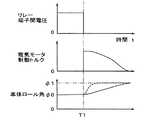
ここで、一定の旋回状態中に故障が発生した状況下での上記の実施形態による効果を、図12を参照して説明する。本実施形態の構成を適用しない場合には、二つのスタビライザバー間に配置され、スタビライザバーの夫々の相対的位置を拘束している電気モータMが、外力(車体に作用する慣性力)によって回されるため、スタビライザのねじり剛性が低下する。この結果、車体ロール角が急増し、図12に破線で示す特性となる。これに対し、本実施形態によれば、時間T1で故障が判定されると、直ちにモータリレーRYが短絡され、各リレー端子間の電圧がゼロとなる。この結果、逆起電力が発生し、電気モータMに制動トルクが生じ、この制動トルクが外力(車体慣性力)による電気モータMの回転を抑制することになる。而して、図12に実線で示すように車体ロール角の増加が抑制され、車体ロール角変化は時間的に緩やかであるため、運転者は故障に対して容易に対応することができる。Here, the effect of the above embodiment under a situation where a failure has occurred during a certain turning state will be described with reference to FIG. When the configuration of the present embodiment is not applied, the electric motor M disposed between the two stabilizer bars and restraining the relative positions of the stabilizer bars is rotated by an external force (inertial force acting on the vehicle body). since the torsional rigidityof the stabilizer decreases. As a result, the roll angle of the vehicle body increases rapidly, and the characteristic indicated by the broken line in FIG. On the other hand, according to the present embodiment, when a failure is determined at time T1, the motor relay RY is immediately short-circuited, and the voltage between the relay terminals becomes zero. As a result, a counter electromotive force is generated, and a braking torque is generated in the electric motor M. This braking torque suppresses the rotation of the electric motor M due to an external force (vehicle body inertia force). Thus, as shown by the solid line in FIG. 12, the increase in the vehicle body roll angle is suppressed, and the vehicle body roll angle change is gradual in time, so that the driver can easily cope with the failure.
また、車体のロール角が発生した後に故障し、その状態が保持された状態で走行しているような場合には、図13に示すように、時間T2で故障の判定が行われ電気モータMへの通電が停止されると、スタビライザバーのねじり作用が急に開放されることになる。このため、図13中に破線で示すように車体ロール角は急激に収まることとなり、運転者に違和感を与える。これに対し、本実施形態によれば、時間T2で故障判定がされた場合には、モータ端子間の短絡回路が形成され、電気モータMに制動トルクが付与されるため、車体ロール角は緩やかに収まることとなり、運転者に違和感を与えることもない。 In the case where the vehicle breaks after the roll angle of the vehicle body is generated and the vehicle is traveling in a state where the state is maintained, as shown in FIG. 13, the failure is determined at time T2, and the electric motor M When the energization to is stopped, the twisting action of the stabilizer bar is suddenly released. For this reason, as shown by a broken line in FIG. 13, the vehicle body roll angle rapidly falls, giving the driver a feeling of strangeness. On the other hand, according to the present embodiment, when a failure determination is made at time T2, a short circuit between the motor terminals is formed and braking torque is applied to the electric motor M, so that the vehicle body roll angle is moderate. The driver will not be uncomfortable.
ところで、故障については、電源系の故障とそれ以外とに分類して考慮する必要がある。まず、電源系の故障について説明する。スタビライザアクチュエータに電源供給されない場合においても、上記のモータ端子間の短絡は確実に行われなければならない。そのため、図4におけるリレーRLY1、RLY2及びRLY3は、電力が供給されない非通電時に短絡されるノーマルクローズ型のリレーが用いられている。そして、システムが作動状態になる場合には、先ず、各リレーが閉位置から開位置に駆動され、モータ端子間の短絡状態が解消され、電気モータMへの通電が行われる。 By the way, the failure needs to be classified into the failure of the power supply system and the other. First, the failure of the power supply system will be described. Even when power is not supplied to the stabilizer actuator, the short circuit between the motor terminals must be performed reliably. For this reason, the relays RLY1, RLY2, and RLY3 in FIG. 4 are normally closed relays that are short-circuited when power is not supplied. When the system is in the operating state, first, each relay is driven from the closed position to the open position, the short-circuit state between the motor terminals is eliminated, and the electric motor M is energized.
更に、電気配線においてコネクタを用いる場合には、コネクタ抜けをも考慮する必要がある。そこで、スタビライザアクチュエータFT(又はRT)がコネクタCNを介して接続される場合には、図5に示すように構成される。この場合において、モータリレーRYはコネクタ抜けに対しても確実にモータ端子間の短絡状態とするため、モータリレーRYはコネクタCNに対して電気モータM側に配置することが望ましい。 Further, when a connector is used in the electrical wiring, it is necessary to consider the disconnection of the connector. Therefore, when the stabilizer actuator FT (or RT) is connected via the connector CN, it is configured as shown in FIG. In this case, the motor relay RY is desirably arranged on the electric motor M side with respect to the connector CN in order to ensure that the motor relay RY is short-circuited between the motor terminals even when the connector is disconnected.
図6は、アクティブロール抑制制御ARCの制御ブロックを示すもので、運転者のハンドル(ステアリング)操作に関し、運転者操作検出手段M11によりハンドル角δfを含む情報が検出され、車両の走行状態検出手段M12により車両速度、横加速度及びヨーレイトを含む車両運動状態量が検出される。これらの情報に基づき、車両の望ましいロール特性を達成するための車両アクティブロールモーメント目標値が演算される(M13)。また、車両挙動判定演算M14においては運転者のハンドル操作と車両運動状態量に基づき車両のステア特性(所謂アンダステア傾向、オーバステア傾向)が判定される。次に、演算されたステア特性と車両運動状態に応じて前輪と後輪のロール剛性比率の目標値が演算される(M15)。車両アクティブロールモーメント及びロール剛性比率の目標値によって前輪及び後輪のアクティブロールモーメントの目標値が演算される(M16)。これらの目標値に基づき前輪及び後輪のスタビライザアクチュエータFT及びRTが制御される(M17)。これらアクチュエータ駆動用の電気モータMの端子間にはモータリレー(図5に代表してRYで示す)が配置され、各モータリレーRYはリレー駆動手段M19によって制御される。リレー駆動手段M19は、故障判定手段M18の判定結果に基づき、故障発生時には、リレー端子間を短絡するように、モータリレーRYが開位置から閉位置に制御される。これにより、故障発生時には電気モータMに制動トルクが働き、車体ロール角の急変が抑制される。 FIG. 6 shows a control block of the active roll suppression control ARC. Regarding the driver's steering (steering) operation, information including the steering wheel angle δf is detected by the driver operation detecting means M11, and the vehicle running state detecting means is detected. M12 detects the vehicle motion state quantity including the vehicle speed, the lateral acceleration, and the yaw rate. Based on these pieces of information, a vehicle active roll moment target value for achieving a desired roll characteristic of the vehicle is calculated (M13). Further, in the vehicle behavior determination calculation M14, the steering characteristic (so-called understeer tendency, oversteer tendency) of the vehicle is determined based on the driver's steering operation and the vehicle motion state quantity. Next, the target value of the roll stiffness ratio between the front wheels and the rear wheels is calculated according to the calculated steer characteristic and the vehicle motion state (M15). Based on the target value of the vehicle active roll moment and the roll rigidity ratio, the target value of the active roll moment of the front wheels and the rear wheels is calculated (M16). Based on these target values, the front and rear wheel stabilizer actuators FT and RT are controlled (M17). Between these terminals of the electric motor M for driving the actuator, a motor relay (represented by RY in FIG. 5) is arranged, and each motor relay RY is controlled by the relay driving means M19. The relay drive means M19 controls the motor relay RY from the open position to the closed position so as to short-circuit between the relay terminals when a failure occurs based on the determination result of the failure determination means M18. Thereby, when a failure occurs, a braking torque acts on the electric motor M, and a sudden change in the vehicle body roll angle is suppressed.
図7は、図6の具体的態様を示すもので、車両アクティブロールモーメント目標値演算部M13において横加速度センサYGの信号から得られる横加速度Gy、これを時間微分する横加速度変化量dGy、ハンドル角(操舵角)δf及び車両速度(車速)Vxから演算される演算横加速度Gye、これを時間微分する演算横加速度変化量dGyeに基づき車両全体でロール運動を抑制するために必要なアクティブロールモーメント量Rmvが演算される。演算横加速度Gyeは以下のように演算される。
Gye =(Vx2・δf)/{L・N・(1+Kh・Vx2)}
ここで、Lはホイールベース、Nはステアリングギア比、Khはスタビリティファクタである。FIG. 7 shows a specific mode of FIG. 6. The vehicle active roll moment target value calculation unit M13 obtains the lateral acceleration Gy obtained from the signal of the lateral acceleration sensor YG, the lateral acceleration change amount dGy obtained by time-differentiating this, and the steering wheel. Active roll moment required to suppress roll motion in the entire vehicle based on a calculated lateral acceleration Gye calculated from an angle (steering angle) δf and a vehicle speed (vehicle speed) Vx, and a calculated lateral acceleration change amount dGye obtained by time-differentiating the calculated lateral acceleration Gye. The quantity Rmv is calculated. The calculated lateral acceleration Gye is calculated as follows.
Gye = (Vx2 · δf) / {L · N · (1 + Kh · Vx2 )}
Here, L is a wheel base, N is a steering gear ratio, and Kh is a stability factor.
而して、好適なロール特性を達成するために車両全体に付与すべきアクティブロールモーメントRmvは、以下の関係式により求められる(ここで、K1、K2、K3、K4は制御ゲイン)。
Rmv = K1・Gy+K2・dGy+K3・Gye+K4・dGye
上記のように、制御演算の遅れやアクチュエータの応答性を補償するために、ハンドル角δfと車速Vxから求められる演算横加速度Gyeとその変化量dGyeが考慮される。Thus, the active roll moment Rmv to be applied to the entire vehicle in order to achieve a suitable roll characteristic is obtained by the following relational expression (where K1, K2, K3, and K4 are control gains).
Rmv = K1 · Gy + K2 · dGy + K3 · Gye + K4 · dGye
As described above, the calculated lateral acceleration Gye obtained from the steering wheel angle δf and the vehicle speed Vx and its change amount dGye are taken into account in order to compensate for the delay in the control calculation and the response of the actuator.
前後輪ロール剛性比率目標値演算部M15においては、ロール剛性の前後比率目標値が以下のように決定される。先ず、車両速度(車速)Vxに基づき前輪側及び後輪側のロール剛性比率の初期値Rsrfo、Rsrroが設定される。前輪ロール剛性比率の初期値Rsrfoは、図14に示すように車両速度が低い状態では低く、高い状態では高くなるように設定され、高速走行においてはアンダステア傾向が強くなるように設定される。そして、後輪ロール剛性配分比率の初期値Rsrroは(1−Rsrfo)で決定される。次に、車両挙動判定演算部M14で演算されるヨーレイト偏差ΔYrに基づき、ロール剛性比率補正値Rsraが演算される。ヨーレイト偏差ΔYrは、車両ステア特性を判別するために、ハンドル角δfと車両速度Vxから目標ヨーレイトYrが演算され実際のヨーレイトと比較される。 In the front and rear wheel roll rigidity ratio target value calculation unit M15, the front and rear ratio target value of roll rigidity is determined as follows. First, initial values Rsrfo and Rsrro of the roll stiffness ratio on the front wheel side and the rear wheel side are set based on the vehicle speed (vehicle speed) Vx. As shown in FIG. 14, the initial value Rsrfo of the front wheel roll stiffness ratio is set so as to be low when the vehicle speed is low, and high when the vehicle speed is high, and so as to increase the understeer tendency at high speeds. The initial value Rsrro of the rear wheel roll stiffness distribution ratio is determined by (1−Rsrfo). Next, the roll stiffness ratio correction value Rsra is calculated based on the yaw rate deviation ΔYr calculated by the vehicle behavior determination calculation unit M14. The yaw rate deviation ΔYr is compared with the actual yaw rate by calculating the target yaw rate Yr from the steering wheel angle δf and the vehicle speed Vx in order to determine the vehicle steering characteristic.
この結果、車両がアンダステア傾向にある場合には前輪側ロール剛性比率を低め、後輪側のそれを高める補正が行われる。逆に、オーバステア傾向にある場合には前輪側ロール剛性比率を高め、後輪側のそれを低める補正が行われる。そして、前輪及び後輪アクティブロールモーメント目標値演算部M16において、車両アクティブロールモーメント目標値Rmv、並びに前後輪ロール剛性比率目標値Rsrf及びRsrrに基づき、前輪及び後輪アクティブロールモーメント目標値Rmf及びRmrが、夫々Rmf=Rmv・Rsrf、Rmr=Rmv・Rsrrとして設定される。前輪及び後輪アクティブロールモーメント目標値Rmf及びRmrに基づき前輪及び後輪用のスタビライザアクチュエータFT及びRTで発生すべきねじり力が決定され、電気モータMが制御されることとなる。 As a result, when the vehicle has an understeer tendency, correction is performed to lower the front-wheel-side roll rigidity ratio and increase it on the rear-wheel side. On the other hand, when the vehicle is in an oversteer tendency, correction is performed to increase the front-wheel-side roll rigidity ratio and decrease it on the rear-wheel side. Then, in the front wheel and rear wheel active roll moment target value calculation unit M16, based on the vehicle active roll moment target value Rmv and the front and rear wheel roll stiffness ratio target values Rsrf and Rsrr, the front wheel and rear wheel active roll moment target values Rmf and Rmr Are set as Rmf = Rmv · Rsrf and Rmr = Rmv · Rsrr, respectively. Based on the front wheel and rear wheel active roll moment target values Rmf and Rmr, the torsional force to be generated in the front and rear wheel stabilizer actuators FT and RT is determined, and the electric motor M is controlled.
図8は電気モータMの制御の一態様を示すもので、アクティブロールモーメント目標値Rmf及びRmrからモータ出力の目標値が演算され(M21)、その結果が実際のモータ出力と比較され、モータ出力偏差が求められる(M22)。更に、この偏差に応じて電気モータMへのPWM出力が決定され(M23)、モータ駆動回路MCにおけるスイッチング素子が制御される。 FIG. 8 shows one mode of control of the electric motor M. The target value of the motor output is calculated from the active roll moment target values Rmf and Rmr (M21), the result is compared with the actual motor output, and the motor output A deviation is determined (M22). Further, the PWM output to the electric motor M is determined according to this deviation (M23), and the switching element in the motor drive circuit MC is controlled.
以上のように、図7及び図8を参照して、基本的なアクティブロール抑制制御について説明したが、次に、故障判定について説明する。故障判定は、先ず、通信バスから得られるセンサ異常フラグに基づいて行われる。アクティブロール抑制制御には、ハンドル角δf、車両速度Vx又はそれを演算するための車輪速度Vwx、横加速度Gy、ヨーレイトYr等の信号が必要となるが、これらは図1に示すように通信バスを介して入力される。各々のセンサは自己診断機能を有しており、診断結果が故障と判定された場合には、センサ異常フラグが通信バス上に発せられる。この場合には、図6の故障判定手段M18により故障と判定され、その情報がリレー駆動手段M19に伝達される。 As described above, the basic active roll suppression control has been described with reference to FIGS. 7 and 8. Next, failure determination will be described. The failure determination is first performed based on a sensor abnormality flag obtained from the communication bus. Active roll suppression control requires signals such as steering wheel angle δf, vehicle speed Vx or wheel speed Vwx for calculating the vehicle speed, lateral acceleration Gy, yaw rate Yr, etc., as shown in FIG. Is input through. Each sensor has a self-diagnosis function, and if the diagnosis result is determined to be a failure, a sensor abnormality flag is issued on the communication bus. In this case, the failure determination unit M18 in FIG. 6 determines that a failure has occurred, and the information is transmitted to the relay drive unit M19.
また、センサ間の相互監視が行われ、所定の関係にある車両状態量間で不整合が生じた場合にはセンサ異常が判定され、異常フラグが通信バス上に載せられる。これは、例えば、通常走行状態では、車両速度Vx、横加速度Gy、ヨーレイトYrは、概略Gy=Yr・Vxの関係にあるが、この関係において、GyとYr・Vxとの偏差が所定値以上となった場合に、故障と判定するものである。 In addition, mutual monitoring between sensors is performed, and when a mismatch occurs between vehicle state quantities having a predetermined relationship, a sensor abnormality is determined, and an abnormality flag is placed on the communication bus. For example, in the normal running state, the vehicle speed Vx, the lateral acceleration Gy, and the yaw rate Yr are approximately in a relationship of Gy = Yr · Vx. In this relationship, the deviation between Gy and Yr · Vx is a predetermined value or more. In this case, it is determined that there is a failure.
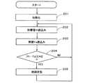
尚、故障判定はアクティブロール抑制制御の各目標値と、各センサからの実側値(実値)に基づいて行うこともでき、これを図4等において故障判定演算としている。図9乃至図11は故障判定演算を示すもので、図9に示す態様では、ステップ101で初期化された後、ステップ102及び103にて目標値の今回値Xnと目標値の前回値Xn-1が読み込まれ、ステップ104においてこれらが比較される。正常な場合には、目標値の今回値Xnと前回値Xn-1とが大きくかけ離れることはない。その偏差の絶対値が大きくなるということは、それを生成する状態量に異常があるためで、この偏差の絶対値が所定値H1以上となった場合には、ステップ105に進み故障と判定される。尚、図9乃至図11における目標値とは、図7及び図8に示される目標値を意味する。 Note that the failure determination can also be performed based on each target value of the active roll suppression control and the actual side value (actual value) from each sensor, which is used as the failure determination calculation in FIG. 9 to 11 show the failure determination calculation. In the embodiment shown in FIG. 9, after the initialization at
次に、図10に示す態様では、ステップ201で初期化された後、ステップ202及び203にて目標値Ytと実値Yaが読み込まれ、ステップ204においてこれらが比較される。目標値Ytと実値Yaの偏差の絶対値が所定値H2以上となった場合にはステップ204にて故障と判定される。図7及び図8に示すアクティブロール抑制制御は、基本的には目標値と実値の偏差に基づいて行われる。即ち、正常な場合には目標値Ytと実値Yaとは大きくかけ離れることはないが、その偏差の絶対値が大きくなるということは、目標値Ytを生成する状態量、あるいは実値Yaを検出するセンサ、演算結果等に異常があるためであり、この偏差の絶対値が所定値H2以上となった場合には、ステップ205に進み故障と判定される。ここで、目標値Yt及び実値Yaとは、図7及び図8に示される目標値、及びセンサ値又は演算値を意味する。 Next, in the mode shown in FIG. 10, after the initialization in
そして、図11に示す態様では、ステップ301で初期化された後、ステップ302に進み、センサにより検出される実値Zaが読み込まれ、ステップ303においてこの実値Zaが所定値H3と比較される。この結果、Za≧H3と判定された場合には故障と判定される。例えば、図3においてモータ駆動回路MCのモータ駆動電流が検出され、所定値以上の過電流となった場合に故障判定が行われる。実値は上限値を持つ場合だけではなく、好適値をもつものもある。例えば、車両が所定の旋回状態にあるにもかかわらず、図3の回転角検出手段RSからの回転角が所定値以上、もしくは、所定値H4以下となる場合にも同様に、ステップ304に進み故障と判定される。 In the mode shown in FIG. 11, after being initialized in
図15は、スタビライザアクチュエータの別の実施形態を示すもので、スタビライザアクチュエータSCAの両端には、2分割されたスタビライザバーSBfr及びSBflが配置され、夫々保持手段HLfr及びHLflに支持されると共に、サスペンションアーム(図示せず)に連結されている。一方のスタビライザバーSBflの軸上には、ねじり剛性を与える電気モータSMが配置されている。この電気モータSMは多極のブラシレスモータで構成され、中空のモータ固定子MS及びモータ回転子MRがスタビライザバーSBflの軸上に配置されている。モータ回転子MRは、両端をベアリングで支持された円筒部材MHに、多極の磁石が取付けられている。また、電気モータSMには、スタビライザバーSBflあるいはスタビライザバーSBfrの軸回転を検出するための回転センサRASが、モータ回転子MR付近に配置されている。この回転センサRASは、リング状に配置された磁石を備え、モータ回転子MRの磁石と同相となるように着磁されている。 FIG. 15 shows another embodiment of the stabilizer actuator, and stabilizer bars SBfr and SBfl divided into two are arranged at both ends of the stabilizer actuator SCA, and are supported by the holding means HLfr and HLfl, respectively, and the suspension. It is connected to an arm (not shown). On the axis of one stabilizer bar SBfl, an electric motor SM that provides torsional rigidity is arranged. The electric motor SM is composed of a multipolar brushless motor, and a hollow motor stator MS and a motor rotor MR are arranged on the axis of the stabilizer bar SBfl. In the motor rotor MR, multipolar magnets are attached to a cylindrical member MH supported at both ends by bearings. Further, the electric motor SM is provided with a rotation sensor RAS for detecting the shaft rotation of the stabilizer bar SBfl or the stabilizer bar SBfr in the vicinity of the motor rotor MR. The rotation sensor RAS includes a magnet arranged in a ring shape and is magnetized so as to be in phase with the magnet of the motor rotor MR.
また、スタビライザアクチュエータSCAには、電気モータSMの回転による駆動力を減速してスタビライザバーSBfr及びSBflに伝達するため、サンギア、プラネタリギア及びリングギアを複数組み合わせて構成された不思議遊星歯車からなる複数段の減速ギアPGUが配置されている。この減速ギアPGUによって、電気モータSMの回転が減速され、スタビライザバーSBfr及びSBflにねじり力が伝達されるように構成されている。尚、この減速ギアPGUで使用されるギアの組合せは電気モータの仕様及びギアの減速比を考慮して決定される。而して、本実施形態においても、スタビライザアクチュエータSCAによってスタビライザバーSBfr及びSBflに対し積極的にねじり剛性を付与するように制御することで、車両の走行時に発生する車体ロールを抑制あるいは低減させることができる。 The stabilizer actuator SCA includes a plurality of magic planetary gears configured by combining a plurality of sun gears, planetary gears, and ring gears in order to decelerate and transmit the driving force generated by the rotation of the electric motor SM to the stabilizer bars SBfr and SBfl. A stage reduction gear PGU is arranged. The reduction gear PGU is configured to reduce the rotation of the electric motor SM and transmit a torsional force to the stabilizer bars SBfr and SBfl. The gear combination used in the reduction gear PGU is determined in consideration of the specifications of the electric motor and the gear reduction ratio. Thus, also in this embodiment, by controlling the stabilizer bars SBfr and SBfl to be positively torsional rigid by the stabilizer actuator SCA, the vehicle body roll generated during the traveling of the vehicle can be suppressed or reduced. Can do.
SBf 前輪側スタビライザ
SBfr,SBfl 前輪側スタビライザバー
SBr 後輪側スタビライザ
FT,RT,SCA スタビライザアクチュエータ
SW ステアリングホイール
SA 操舵角センサ
WHfr, WHfl, WHrr, WHrl 車輪
WSfr,WSfl,WSrr,WSrl 車輪速度センサ
YR ヨーレイトセンサ
XG 前後加速度センサ
YG 横加速度センサ
ECU 電子制御装置
SBf Front wheel side stabilizer SBfr, SBfl Front wheel side stabilizer bar SBr Rear wheel side stabilizer FT, RT, SCA Stabilizer actuator SW Steering wheel SA Steering angle sensor WHfr, WHfl, WHrr, WHrl Wheel WSfr, WSfl, WSrr, WSr R Sensor XG Longitudinal acceleration sensor YG Lateral acceleration sensor ECU Electronic control unit
Claims (3)
Translated fromJapanesePriority Applications (5)
| Application Number | Priority Date | Filing Date | Title |
|---|---|---|---|
| JP2003426396AJP4438406B2 (en) | 2003-06-27 | 2003-12-24 | Stabilizer control device |
| EP04014845AEP1491371B1 (en) | 2003-06-27 | 2004-06-24 | Stabilizer control device |
| US10/874,536US7322580B2 (en) | 2003-06-27 | 2004-06-24 | Stabilizer control device |
| DE602004014069TDE602004014069D1 (en) | 2003-06-27 | 2004-06-24 | stabilizer control |
| CNB2004100618373ACN100377952C (en) | 2003-06-27 | 2004-06-25 | Stabilizer control device |
Applications Claiming Priority (2)
| Application Number | Priority Date | Filing Date | Title |
|---|---|---|---|
| JP2003185600 | 2003-06-27 | ||
| JP2003426396AJP4438406B2 (en) | 2003-06-27 | 2003-12-24 | Stabilizer control device |
Publications (2)
| Publication Number | Publication Date |
|---|---|
| JP2005035515A JP2005035515A (en) | 2005-02-10 |
| JP4438406B2true JP4438406B2 (en) | 2010-03-24 |
Family
ID=33422223
Family Applications (1)
| Application Number | Title | Priority Date | Filing Date |
|---|---|---|---|
| JP2003426396AExpired - Fee RelatedJP4438406B2 (en) | 2003-06-27 | 2003-12-24 | Stabilizer control device |
Country Status (5)
| Country | Link |
|---|---|
| US (1) | US7322580B2 (en) |
| EP (1) | EP1491371B1 (en) |
| JP (1) | JP4438406B2 (en) |
| CN (1) | CN100377952C (en) |
| DE (1) | DE602004014069D1 (en) |
Families Citing this family (45)
| Publication number | Priority date | Publication date | Assignee | Title |
|---|---|---|---|---|
| JP2006076377A (en)* | 2004-09-08 | 2006-03-23 | Toyota Motor Corp | Stabilizer device |
| JP4455987B2 (en)* | 2004-12-28 | 2010-04-21 | トヨタ自動車株式会社 | Vehicle stabilizer system |
| JP4506522B2 (en) | 2005-03-16 | 2010-07-21 | トヨタ自動車株式会社 | Suspension system |
| DE102005021673A1 (en)* | 2005-05-11 | 2006-11-16 | Bayerische Motoren Werke Ag | Divided electromechanical motor vehicle stabilizer with blocking device and method for roll stabilization in case of failure or shutdown of the active motor vehicle stabilizer |
| JP4297085B2 (en)* | 2005-06-16 | 2009-07-15 | トヨタ自動車株式会社 | Vehicle stabilizer system |
| JP4240010B2 (en)* | 2005-06-16 | 2009-03-18 | トヨタ自動車株式会社 | Vehicle stabilizer system |
| JP4404018B2 (en)* | 2005-06-16 | 2010-01-27 | トヨタ自動車株式会社 | Vehicle stabilizer system |
| JP2007030575A (en)* | 2005-07-25 | 2007-02-08 | Aisin Seiki Co Ltd | Stabilizer control device |
| JP4770328B2 (en)* | 2005-08-19 | 2011-09-14 | アイシン精機株式会社 | Stabilizer control device |
| JP4341632B2 (en) | 2006-02-21 | 2009-10-07 | トヨタ自動車株式会社 | Stabilizer control device |
| JP4438763B2 (en)* | 2006-03-20 | 2010-03-24 | トヨタ自動車株式会社 | Vehicle stabilizer system |
| US7717410B2 (en)* | 2006-10-24 | 2010-05-18 | Wieslaw Julian Oledzki | Smooth non-linear springs, particularly smooth progressive rate steel springs, progressive rate vehicle suspensions and method |
| US7832739B2 (en)* | 2006-11-06 | 2010-11-16 | American Axle & Manufacturing, Inc. | Apparatus and method for coupling a disconnectable stabilizer bar |
| DE102007017242A1 (en)* | 2007-04-12 | 2008-10-16 | Dr. Ing. H.C. F. Porsche Aktiengesellschaft | Method and device for roll stabilization of a motor vehicle |
| DE102007040185A1 (en) | 2007-08-25 | 2009-02-26 | Bayerische Motoren Werke Aktiengesellschaft | Chassis for motor vehicle, has two stabilizer parts attached to spring part of motor vehicle by respective fastening devices in rotatably movable manner, where fastening device has progressively increasing spring characteristics |
| US7887072B2 (en)* | 2008-10-09 | 2011-02-15 | American Axle & Manufacturing, Inc. | Stabilizer bar with disconnectable link |
| US9162573B2 (en) | 2010-06-03 | 2015-10-20 | Polaris Industries Inc. | Electronic throttle control |
| GB201014276D0 (en)* | 2010-08-26 | 2010-10-13 | Imp Innovations Ltd | Variable-geometry suspension apparatus and vehicle comprising such apparatus |
| DE102011002341A1 (en) | 2011-04-29 | 2012-10-31 | Benteler Automobiltechnik Gmbh | Method for regulating and controlling twisting moment of semi-active stabilizer of motor vehicle e.g. off-road vehicle, involves controlling and regulating control valve in dependence of accelerations and/or velocity and/or steering angle |
| JP2012253404A (en) | 2011-05-31 | 2012-12-20 | Renesas Electronics Corp | Semiconductor device |
| DE102012107507B4 (en)* | 2012-08-16 | 2025-03-13 | Dr. Ing. H.C. F. Porsche Aktiengesellschaft | Stabilizer arrangement for a chassis of a motor vehicle |
| DE102012110656A1 (en)* | 2012-11-07 | 2014-05-08 | Dr. Ing. H.C. F. Porsche Aktiengesellschaft | Stabilizer arrangement for a chassis of a motor vehicle |
| US9205717B2 (en) | 2012-11-07 | 2015-12-08 | Polaris Industries Inc. | Vehicle having suspension with continuous damping control |
| DE102013223424B4 (en)* | 2013-07-17 | 2021-03-04 | Schaeffler Technologies AG & Co. KG | Method for operating a motor vehicle to detect excessive stress on a roll stabilizer |
| CN103568773A (en)* | 2013-11-19 | 2014-02-12 | 浙江吉利汽车研究院有限公司 | Stabilizer bar device of automobile |
| CN107406094B (en) | 2014-10-31 | 2020-04-14 | 北极星工业有限公司 | System and method for controlling a vehicle |
| DE202015101123U1 (en) | 2015-03-05 | 2015-03-13 | Ford Global Technologies, Llc | Semi-active stabilizer arrangement for a chassis of a vehicle |
| DE102015203906A1 (en) | 2015-03-05 | 2016-09-08 | Ford Global Technologies, Llc | Semi-active stabilizer arrangement for a chassis of a vehicle |
| DE102015203907A1 (en) | 2015-03-05 | 2016-09-08 | Ford Global Technologies, Llc | Semi-active stabilizer arrangement for a chassis of a vehicle |
| DE102016215004B4 (en)* | 2016-08-11 | 2018-12-27 | Schaeffler Technologies AG & Co. KG | Method for operating an electric servomotor, roll stabilizer device and vehicle |
| US10618370B2 (en)* | 2016-09-02 | 2020-04-14 | Mando Corporation | Active roll stabilizer |
| CN110121438B (en) | 2016-11-18 | 2023-01-31 | 北极星工业有限公司 | vehicles with adjustable suspension |
| JP6573082B2 (en)* | 2017-04-03 | 2019-09-11 | トヨタ自動車株式会社 | Roll control device for vehicle |
| US10406884B2 (en) | 2017-06-09 | 2019-09-10 | Polaris Industries Inc. | Adjustable vehicle suspension system |
| US10650620B2 (en) | 2017-09-11 | 2020-05-12 | GM Global Technology Operations LLC | Systems and methods to determine abnormalities in a vehicle stabilizer system |
| JP7132703B2 (en)* | 2017-09-12 | 2022-09-07 | 日立Astemo株式会社 | Vehicle motion state estimation device, vehicle motion state estimation system, vehicle motion control device, and vehicle motion state estimation method |
| US10987987B2 (en) | 2018-11-21 | 2021-04-27 | Polaris Industries Inc. | Vehicle having adjustable compression and rebound damping |
| DE102019213280B4 (en)* | 2019-09-03 | 2023-03-30 | Zf Friedrichshafen Ag | Method of operating an adjustable roll stabilizer |
| US12397878B2 (en) | 2020-05-20 | 2025-08-26 | Polaris Industries Inc. | Systems and methods of adjustable suspensions for off-road recreational vehicles |
| DE102020114570A1 (en)* | 2020-05-29 | 2021-12-02 | Bayerische Motoren Werke Aktiengesellschaft | Device and method for operating a roll stabilization system |
| MX2022015902A (en) | 2020-07-17 | 2023-01-24 | Polaris Inc | Adjustable suspensions and vehicle operation for off-road recreational vehicles. |
| JP7288922B2 (en)* | 2021-03-25 | 2023-06-08 | 本田技研工業株式会社 | electric suspension device |
| GB2618367B (en)* | 2022-05-05 | 2024-07-31 | Jaguar Land Rover Ltd | Vehicle roll control |
| CN116001509B (en)* | 2022-11-08 | 2023-09-19 | 江苏克瑞迪机车有限公司 | Suspension for all-terrain vehicle convenient to adjust and use method |
| JP2025032496A (en)* | 2023-08-28 | 2025-03-12 | トヨタ自動車株式会社 | Suspension system |
Family Cites Families (11)
| Publication number | Priority date | Publication date | Assignee | Title |
|---|---|---|---|---|
| US4981309A (en)* | 1989-08-31 | 1991-01-01 | Bose Corporation | Electromechanical transducing along a path |
| US5028073A (en)* | 1990-01-08 | 1991-07-02 | General Electric Company | Dynamic vehicle suspension system including electronically commutated motor |
| US5441298A (en) | 1993-10-22 | 1995-08-15 | Ford Motor Company | Apparatus for stabilizing an electric active suspension system upon interruption of the power supply |
| JP3161381B2 (en)* | 1997-10-06 | 2001-04-25 | 株式会社豊田自動織機製作所 | Oscillation control device for industrial vehicles |
| US6076837A (en)* | 1998-02-03 | 2000-06-20 | Ford Motor Company | Method and apparatus for improving quality of actuator motion in a vehicle active tilt control system |
| EP1030790B1 (en) | 1998-06-25 | 2004-06-02 | Robert Bosch Gmbh | Process and system for stabilising vehicles against rolling |
| DE19846275A1 (en) | 1998-06-25 | 1999-12-30 | Bosch Gmbh Robert | System for roll-stabilization of vehicles, especially cars |
| AU2002330900A1 (en)* | 2001-07-19 | 2003-03-03 | Stoneridge Control Devices, Inc. | Failsafe smart bar actuator |
| US6679504B2 (en)* | 2001-10-23 | 2004-01-20 | Liquidspring Technologies, Inc. | Seamless control of spring stiffness in a liquid spring system |
| DE10221716A1 (en) | 2002-05-16 | 2003-11-27 | Bayerische Motoren Werke Ag | Control system for a motor vehicle with roll stabilization |
| DE10257211A1 (en)* | 2002-12-07 | 2004-06-24 | Bayerische Motoren Werke Ag | Shared electromechanical motor vehicle stabilizer and method for roll stabilization in the event of failure or deactivation of the active motor vehicle stabilizer |
- 2003
- 2003-12-24JPJP2003426396Apatent/JP4438406B2/ennot_activeExpired - Fee Related
- 2004
- 2004-06-24DEDE602004014069Tpatent/DE602004014069D1/ennot_activeExpired - Lifetime
- 2004-06-24EPEP04014845Apatent/EP1491371B1/ennot_activeExpired - Lifetime
- 2004-06-24USUS10/874,536patent/US7322580B2/ennot_activeExpired - Lifetime
- 2004-06-25CNCNB2004100618373Apatent/CN100377952C/ennot_activeExpired - Fee Related
Also Published As
| Publication number | Publication date |
|---|---|
| EP1491371A1 (en) | 2004-12-29 |
| DE602004014069D1 (en) | 2008-07-10 |
| US20050023789A1 (en) | 2005-02-03 |
| CN100377952C (en) | 2008-04-02 |
| JP2005035515A (en) | 2005-02-10 |
| EP1491371B1 (en) | 2008-05-28 |
| US7322580B2 (en) | 2008-01-29 |
| CN1576135A (en) | 2005-02-09 |
Similar Documents
| Publication | Publication Date | Title |
|---|---|---|
| JP4438406B2 (en) | Stabilizer control device | |
| JP4336217B2 (en) | Stabilizer control device | |
| US7384047B2 (en) | Stabilizer control apparatus | |
| JP4779652B2 (en) | Stabilizer control device | |
| US7301295B2 (en) | Stabilizer control device | |
| EP1893429B1 (en) | Vehicle stabilizer system | |
| CN101405155A (en) | Vehicle stabilizer system | |
| JP4728363B2 (en) | Steering control device | |
| WO2005077684A1 (en) | Stabilizer controller | |
| CN107031715A (en) | The backup mode of active roll control system | |
| JP2009029257A (en) | Roll control system for vehicles | |
| JP4294525B2 (en) | Stabilizer control device | |
| JP2005255012A (en) | Stabilizer control device | |
| JP2005145360A (en) | Suspension control device | |
| JP2006021742A (en) | Roll motion control device for vehicle | |
| JP2007186073A (en) | Vehicle stabilizer system | |
| JP2010052515A (en) | Electromagnetic type actuating device control system | |
| JP2010228721A (en) | Lane departure warning device |
Legal Events
| Date | Code | Title | Description |
|---|---|---|---|
| A621 | Written request for application examination | Free format text:JAPANESE INTERMEDIATE CODE: A621 Effective date:20061122 | |
| A977 | Report on retrieval | Free format text:JAPANESE INTERMEDIATE CODE: A971007 Effective date:20090408 | |
| A131 | Notification of reasons for refusal | Free format text:JAPANESE INTERMEDIATE CODE: A131 Effective date:20090421 | |
| A521 | Request for written amendment filed | Free format text:JAPANESE INTERMEDIATE CODE: A523 Effective date:20090525 | |
| TRDD | Decision of grant or rejection written | ||
| A01 | Written decision to grant a patent or to grant a registration (utility model) | Free format text:JAPANESE INTERMEDIATE CODE: A01 Effective date:20091215 | |
| A01 | Written decision to grant a patent or to grant a registration (utility model) | Free format text:JAPANESE INTERMEDIATE CODE: A01 | |
| A61 | First payment of annual fees (during grant procedure) | Free format text:JAPANESE INTERMEDIATE CODE: A61 Effective date:20091228 | |
| FPAY | Renewal fee payment (event date is renewal date of database) | Free format text:PAYMENT UNTIL: 20130115 Year of fee payment:3 | |
| R151 | Written notification of patent or utility model registration | Ref document number:4438406 Country of ref document:JP Free format text:JAPANESE INTERMEDIATE CODE: R151 | |
| FPAY | Renewal fee payment (event date is renewal date of database) | Free format text:PAYMENT UNTIL: 20130115 Year of fee payment:3 | |
| FPAY | Renewal fee payment (event date is renewal date of database) | Free format text:PAYMENT UNTIL: 20130115 Year of fee payment:3 | |
| FPAY | Renewal fee payment (event date is renewal date of database) | Free format text:PAYMENT UNTIL: 20140115 Year of fee payment:4 | |
| LAPS | Cancellation because of no payment of annual fees |