JP4437317B2 - Bioabsorbable fasteners for use in wound closure - Google Patents
Bioabsorbable fasteners for use in wound closureDownload PDFInfo
- Publication number
- JP4437317B2 JP4437317B2JP2004516263AJP2004516263AJP4437317B2JP 4437317 B2JP4437317 B2JP 4437317B2JP 2004516263 AJP2004516263 AJP 2004516263AJP 2004516263 AJP2004516263 AJP 2004516263AJP 4437317 B2JP4437317 B2JP 4437317B2
- Authority
- JP
- Japan
- Prior art keywords
- fastener
- staple
- tissue
- region
- arm
- Prior art date
- Legal status (The legal status is an assumption and is not a legal conclusion. Google has not performed a legal analysis and makes no representation as to the accuracy of the status listed.)
- Expired - Lifetime
Links
Images


Classifications
- A—HUMAN NECESSITIES
- A61—MEDICAL OR VETERINARY SCIENCE; HYGIENE
- A61B—DIAGNOSIS; SURGERY; IDENTIFICATION
- A61B17/00—Surgical instruments, devices or methods
- A61B17/064—Surgical staples, i.e. penetrating the tissue
- A61B17/0644—Surgical staples, i.e. penetrating the tissue penetrating the tissue, deformable to closed position
- A—HUMAN NECESSITIES
- A61—MEDICAL OR VETERINARY SCIENCE; HYGIENE
- A61B—DIAGNOSIS; SURGERY; IDENTIFICATION
- A61B17/00—Surgical instruments, devices or methods
- A61B17/064—Surgical staples, i.e. penetrating the tissue
- A—HUMAN NECESSITIES
- A61—MEDICAL OR VETERINARY SCIENCE; HYGIENE
- A61B—DIAGNOSIS; SURGERY; IDENTIFICATION
- A61B17/00—Surgical instruments, devices or methods
- A61B17/068—Surgical staplers, e.g. containing multiple staples or clamps
- A—HUMAN NECESSITIES
- A61—MEDICAL OR VETERINARY SCIENCE; HYGIENE
- A61B—DIAGNOSIS; SURGERY; IDENTIFICATION
- A61B17/00—Surgical instruments, devices or methods
- A61B17/068—Surgical staplers, e.g. containing multiple staples or clamps
- A61B17/0682—Surgical staplers, e.g. containing multiple staples or clamps for applying U-shaped staples or clamps, e.g. without a forming anvil
- A—HUMAN NECESSITIES
- A61—MEDICAL OR VETERINARY SCIENCE; HYGIENE
- A61B—DIAGNOSIS; SURGERY; IDENTIFICATION
- A61B17/00—Surgical instruments, devices or methods
- A61B17/28—Surgical forceps
- A61B17/2812—Surgical forceps with a single pivotal connection
- A61B17/282—Jaws
- A—HUMAN NECESSITIES
- A61—MEDICAL OR VETERINARY SCIENCE; HYGIENE
- A61B—DIAGNOSIS; SURGERY; IDENTIFICATION
- A61B17/00—Surgical instruments, devices or methods
- A61B17/30—Surgical pincettes, i.e. surgical tweezers without pivotal connections
- A—HUMAN NECESSITIES
- A61—MEDICAL OR VETERINARY SCIENCE; HYGIENE
- A61B—DIAGNOSIS; SURGERY; IDENTIFICATION
- A61B17/00—Surgical instruments, devices or methods
- A61B2017/00004—(bio)absorbable, (bio)resorbable or resorptive
- A—HUMAN NECESSITIES
- A61—MEDICAL OR VETERINARY SCIENCE; HYGIENE
- A61B—DIAGNOSIS; SURGERY; IDENTIFICATION
- A61B17/00—Surgical instruments, devices or methods
- A61B17/08—Wound clamps or clips, i.e. not or only partly penetrating the tissue ; Devices for bringing together the edges of a wound
- A61B2017/081—Tissue approximator
Landscapes
- Health & Medical Sciences (AREA)
- Life Sciences & Earth Sciences (AREA)
- Surgery (AREA)
- Heart & Thoracic Surgery (AREA)
- Engineering & Computer Science (AREA)
- Biomedical Technology (AREA)
- Nuclear Medicine, Radiotherapy & Molecular Imaging (AREA)
- Medical Informatics (AREA)
- Molecular Biology (AREA)
- Animal Behavior & Ethology (AREA)
- General Health & Medical Sciences (AREA)
- Public Health (AREA)
- Veterinary Medicine (AREA)
- Surgical Instruments (AREA)
- Prostheses (AREA)
Description
Translated fromJapanese本発明は概ね創傷閉鎖に使用するための外科的ファスナーの分野に関するものである。より詳細に述べれば、本発明は、ファスナーの初期静的強度より大きい創傷応力にさらされた際に再形成する能力を有し、その一方で治癒過程中、創傷の対置する側面を持続的に保持し、近づけることができる、創傷を横切る徹底挿入(through and through insertion)のために設計された動力学的生体内吸収性ファスナーに関する。 The present invention relates generally to the field of surgical fasteners for use in wound closure. More particularly, the present invention has the ability to re-form when exposed to wound stress greater than the initial static strength of the fastener, while maintaining the facing side of the wound during the healing process. It relates to a kinetic bioresorbable fastener designed for through and through insertion across a wound that can be held and approximated.
意図的切開または事故による創傷または裂傷によって組織に開口が生成されると、その開口の生物学的治癒は対置する生体組織面の接合から始まる。開口が非常に大きいかまたはその位置によって創傷が絶えず動くような場合、医師はその開口の側面を強制的にまとめ、治癒過程を促進することを考える。 When an opening is created in tissue by intentional incision or accidental wound or laceration, the biological healing of the opening begins with the joining of the opposing biological tissue surfaces. If the opening is very large or the wound moves constantly depending on its location, the physician will consider forcing the sides of the opening together to promote the healing process.
例えば皮膚組織の場合、皮膚組織の対置する真皮層が互いにぴったり接合している場合、に最もよく治癒する。ヒトの皮膚組織は明確に3層の組織からなる。表皮層(epidermal layerまたはepidermis)は最も外側の層であり、生きていない組織細胞を含む。真皮層(dermal layerまたはdermis)は表皮層の直ぐ下にある中間層であり、生きている皮膚組織からなり、3層のなかでは最も強い。皮下層(subcutaneousまたはhypodermis)は皮膚組織の最下層であり、結合組織が比較的少なく、そのため皮膚組織のなかでは最も弱い層である。 For example, in the case of skin tissue, healing is best when the opposing dermis layers of the skin tissue are tightly joined to each other. Human skin tissue is clearly composed of three layers of tissue. The epidermal layer (epidermis) is the outermost layer and contains non-living tissue cells. The dermis layer (dermis layer or dermis) is an intermediate layer just below the epidermis layer, which is composed of living skin tissue and is the strongest of the three layers. The subcutaneous layer (subcutaneous or hypodermis) is the lowest layer of skin tissue and has relatively few connective tissues and is therefore the weakest layer of skin tissue.
組織開口を強制的に閉鎖する最も一般的な方法は縫合または“ステッチ(ひと針縫合)”を使用することである。早くも二世紀には、ギリシャ人は皮膚創傷を物理的に閉鎖するために縫合を用いていた。縫合の最も簡単な形では、ある長さの材料を針のような組織穿孔器具に取り付け、組織開口の対置する側面を通してループにするだけである。縫合糸をしっかり引っ張り、ループを閉じ、組織開口の対置する側面を物理的にぴったり接触させる。縫合糸ループは結び目(1つ以上)の形成、またはその他の固定メカニズムによってしっかりと固定される。最初、縫合糸は動物の腸から作られた。最終的にはレザー、馬の毛、フラックス(亜麻の繊維)、綿および絹など、その他の天然縫合材料が使用された。医学および材料工学科学が過去一世紀間に進歩するにつれて、新しい生体内吸収性材料が開発され、基礎的縫合概念はさらに改善されるに至った。 The most common method for forcibly closing a tissue opening is to use a suture or “stitch”. As early as two centuries, Greeks used sutures to physically close skin wounds. In the simplest form of suturing, a length of material is simply attached to a tissue drilling instrument such as a needle and looped through the opposing side of the tissue opening. Pull the suture firmly, close the loop, and bring the opposing side of the tissue opening into physical close contact. The suture loop is secured by the formation of a knot (one or more) or other securing mechanism. Initially, sutures were made from the intestines of animals. Eventually other natural suture materials such as leather, horse hair, flux (flax fiber), cotton and silk were used. As medical and material engineering science has advanced over the past century, new bioabsorbable materials have been developed and the basic suturing concept has been further improved.
伝統的縫合は相変わらず皮膚開口の閉鎖のための一般的方法であるが、皮膚閉鎖法としてステープルおよびステープラーなどのファスナー類の使用がますます一般化しつつあり、特に意図的切開によって開口が形成される外科領域ではなおさらである。これらの場合、切開は清潔で真っすぐなカットを形成する傾向があり、その切開の対置側面はぴったりとフィットする、ぎざぎざのない表面を有する。例えば皮膚開口のステープリングは、皮膚開口の対置する側面を手で近づけ、その後にステープルがその開口をつなぐようにステープラーを置くというやり方が普通である。それからステープラーを操作し、ステープルを皮膚に打ち込み、一つの脚が皮膚開口の各側面に入り、ステープルのクロス−メンバが皮膚開口を横切るようにする。一般にはステープルは手術用ステンレス鋼のような変形し得る材料から作られ、ステープルの両脚はアンビルに打ち込まれ、ステープルは、皮膚組織をそのステープル内に圧縮して保持するように変形する。このプロセスを開口の全長に沿って繰り返し、全切開部分が治癒過程中閉鎖されたままになる。 Traditional sutures are still a common method for closing skin openings, but the use of fasteners such as staples and staplers is becoming more and more common as skin closure methods, and openings are formed especially by intentional incisions. This is especially true in the surgical field. In these cases, the incision tends to form a clean and straight cut, and the opposing side of the incision has a jagged surface that fits snugly. For example, the stapling of a skin opening is usually done by approaching the opposite sides of the skin opening by hand and then placing the stapler so that the staples connect the opening. The stapler is then manipulated to drive the staples into the skin so that one leg enters each side of the skin opening and the staple cross-member crosses the skin opening. Generally, staples are made from a deformable material such as surgical stainless steel, both legs of the staple are driven into the anvil, and the staples are deformed to compress and hold the skin tissue within the staples. This process is repeated along the entire length of the opening, leaving the entire incision closed during the healing process.
以前の医科用ステープルの設計は金属からなり、掴んだ組織の周囲に変形するように設計されていた。これらのステープルの例としては米国特許第2,684,070号、第3,273,562号および第4,485,816号がある。有効とはいえ、金属ステープルは術後に除去しなければならないという欠点を有する。医科用ポリマー科学が進歩するにつれ、生体内吸収性材料を組み込んだステープルの設計が可能になった。これらの生体内吸収性材料の使用により、ステープル類の術後の除去が不必要になった。これらのステープルの例としては米国特許第3,757,629号、第4,317,451号、第4,741,337号、第4,839,130号および第4,950,258号がある。しかし、生体内吸収性ポリマーの性質により、生体内吸収性ステープル類は金属ステープルで使用される同じ変形法で挿入することはできない。実際、生体内吸収性ステープルは故意にいかなる変形要求も避けるように設計された。これは、変形が失敗の可能性のあるメカニズムと考えられたからである。このような設計の一例は米国特許第5,089,009の内側に曲がった皮膚ファスナーによって例示される。こうして、考案される生体内吸収性外科的ステープルの物理的および化学的特性として、生体内吸収性ステープルと関連する設計および挿入法の開発は生体内吸収性ファスナーの変形の回避に焦点があてられた。 Previous medical staple designs were made of metal and designed to deform around the grasped tissue. Examples of these staples include US Pat. Nos. 2,684,070, 3,273,562 and 4,485,816. Although effective, metal staples have the disadvantage that they must be removed after surgery. As medical polymer science has advanced, it has become possible to design staples incorporating bioabsorbable materials. The use of these bioabsorbable materials eliminates the need for post-operative removal of staples. Examples of these staples include U.S. Pat. Nos. 3,757,629, 4,317,451, 4,741,337, 4,839,130, and 4,950,258. . However, due to the nature of the bioabsorbable polymer, the bioabsorbable staples cannot be inserted with the same variation used in metal staples. In fact, bioabsorbable staples were purposely designed to avoid any deformation requirements. This is because deformation was considered a possible failure mechanism. An example of such a design is illustrated by a skin fastener bent inside US Pat. No. 5,089,009. Thus, as the physical and chemical properties of the bioabsorbable surgical staple devised, the development of the design and insertion method associated with the bioabsorbable staple has been focused on avoiding deformation of the bioabsorbable fastener. It was.
生体内吸収性ファスナーの考えられる一つの用途は、例えばグリーン(Green)らの一連の特許、米国特許第5,292,326号、第5,389,102号、第5,423,856号、第5,489,287号および第5,573,541号に示されるように、皮膚創傷の閉鎖に使用するファスナーの表皮下適用にある。これらの特許は、表皮下に挿入された生体内吸収性棒状ファスナーの使用によって治癒過程が促進されることを開示している。表皮下創傷閉鎖のために考えられたまた別の生体内吸収性ファスナーの設計はグリスキーウィツ(Gryskiewicz)の米国特許第5,618,311号であり、そのなかではより伝統的なステープル設計が発案されている。 One possible use of the bioabsorbable fastener is, for example, a series of patents by Green et al., US Pat. Nos. 5,292,326, 5,389,102, 5,423,856, As shown in US Pat. Nos. 5,489,287 and 5,573,541, it is in the subepidermal application of fasteners used to close skin wounds. These patents disclose that the healing process is accelerated by the use of a bioabsorbable rod fastener inserted under the epidermis. Another bioabsorbable fastener design contemplated for subepidermal wound closure is Gryskiewicz US Pat. No. 5,618,311, in which a more traditional staple design is It has been invented.
これらの設計の生体内吸収性ステープルが効果的に組織を保持するならば、これらには従来の金属ステープルにまさる多くの利点、例えば目に見える傷痕が残らない、医師が後に除去する必要がない、などがある。残念なことに、今日までの生体内吸収性ステープルの設計は一つとして医学的または市販の効果的ファスナーに取り入れられなかった。生体内吸収性材料の利点を生かし、なお効果的創傷閉鎖をもたらすことができる創傷閉鎖用生体内吸収性ファスナーを提供することが望まれる。 If the bioabsorbable staples of these designs effectively hold tissue, they have many advantages over conventional metal staples, such as no visible scars, and no need for doctors to remove them later. ,and so on. Unfortunately, bioabsorbable staple designs to date have not been incorporated into medical or commercially available effective fasteners as one. It would be desirable to provide a bioabsorbable fastener for wound closure that takes advantage of bioabsorbable materials and can still provide effective wound closure.
本発明は組織損傷の対置する側面の穿孔開口に挿入するための生体内吸収性ファスナーである。ファスナー体部は実質的に生体内吸収性ポリマー材料から形成され、ファスナー体部に対して内側の初期組織捕獲領域を輪郭づける。ファスナー体部は一対のファスナーアーム、肘部分で各ファスナーアームに操作可能に結合するクリート、および肩部分で各ファスナーアームに操作可能に結合するバックスパンを含む。各ファスナーアームは穿孔開口の一つに挿入できる。各クリートは後方に、初期組織捕獲領域に突き出し、その際クリートとファスナーアームとの間に肘内角が形成される。各ファスナーアームの持久的組織保持領域がクリートとファスナーアームとの間に形成される。各ファスナーアームは、クリートおよびファスナーアームの最外部表面間で決まる最大挿入巾を有する。それぞれの肩内角がバックスパンと各ファスナーアームとの間に形成され、バックスパンの中心点と各持久的組織保持領域の先端との間にミッドスパン内角が形成される。 The present invention is a bioabsorbable fastener for insertion into a perforated opening on the side where tissue damage is placed. The fastener body is substantially formed from a bioabsorbable polymer material and outlines an initial initial tissue capture region relative to the fastener body. The fastener body includes a pair of fastener arms, a cleat operably coupled to each fastener arm at the elbow portion, and a backspan operably coupled to each fastener arm at the shoulder portion. Each fastener arm can be inserted into one of the perforated openings. Each cleat protrudes rearward into the initial tissue capture region, where an elbow angle is formed between the cleat and the fastener arm. A permanent tissue retention region for each fastener arm is formed between the cleat and the fastener arm. Each fastener arm has a maximum insertion width determined between the cleat and the outermost surface of the fastener arm. Each shoulder interior angle is formed between the backspan and each fastener arm, and a midspan interior angle is formed between the center point of the backspan and the tip of each permanent tissue holding region.
各ファスナーアームの肘部分および肘内角は、最大挿入巾が対応する穿孔開口の巾より大きくなるように作られ、それによって穿孔開口周囲の組織の少なくとも一部分がクリート上に引き伸ばされ、生体内吸収性ポリマー材料の最短分解期間より長期間、上記持久的組織保持領域中に弾力的に保持されるようになる。肩部分および肩内角は、ファスナーの装着期間中初期組織捕獲領域内で創傷組織を掴み、その後、装着後に創傷組織によってかかる横方向応力に応じて動力学的に再形成(reform)され、生体内吸収性ポリマー材料の最短分解期間まではその生体内吸収性ポリマー材料が破損による失敗に終わることなく、肘内角とミッドスパン内角との合計が360度未満に留まるように作られる。 The elbow portion and the elbow angle of each fastener arm is made such that the maximum insertion width is greater than the corresponding perforation opening width, thereby stretching at least a portion of the tissue around the perforation opening onto the cleat and in vivo absorbability It will be held elastically in the permanent tissue holding region for longer than the shortest degradation period of the polymeric material. The shoulder portion and the shoulder angle grasp the wound tissue in the initial tissue capture region during the fastener application period, and then are dynamically remodeled according to the lateral stress applied by the wound tissue after installation, Up to the shortest degradation period of the absorbent polymer material, the bioabsorbable polymer material is made such that the sum of the elbow angle and the midspan angle remains less than 360 degrees without failure due to breakage.
組織ファスナーのための生体内吸収性材料の使用は多くの利点を有するが、その一方で、外科用ファスナーの設計に生体内吸収性材料を効果的に使用するには、生体内吸収性材料およびヒト組織の性質、並びに組織治癒の動力学的プロセスに関連する多数の問題を理解し、克服しなければならないことが、本発明によって始めて認識された。 While the use of bioabsorbable materials for tissue fasteners has many advantages, in order to effectively use bioabsorbable materials in the design of surgical fasteners, bioabsorbable materials and It was for the first time recognized by the present invention that a number of problems associated with the nature of human tissue as well as the kinetic process of tissue healing must be understood and overcome.
先ず、一般的生体内吸収性ステープルに使われる熱可塑性ポリマーは、持続的応力負荷にさらされる際には、それらの分子レベルの接着およびからみ合う性質によって、粘弾性または重合体クリープをあらわす。生体内吸収性ファスナー設計は、このクリープを相殺するために、バックスパンまたはステープル脚を厚くしてステープルの変形を阻止または減らすか、もしくはこのような変形を避けるために、保持クリップまたはラッチをつけるのが普通であった。ポリマーの粘弾性を相殺することを試みる代わりに、本発明はこれらの特性を利用して、組織の横方向の力に対する動力学的反応を提供する。この動力学的反応は、ファスナーのクリートが持久的組織保持領域内の組織を放出しない限度でファスナーを変形することができる。 First, thermoplastic polymers used in common bioabsorbable staples exhibit viscoelasticity or polymer creep due to their molecular adhesion and entanglement properties when exposed to sustained stress loads. The bioabsorbable fastener design thickens the backspan or staple legs to counteract this creep and prevent or reduce staple deformation or attach retaining clips or latches to avoid such deformation It was normal. Instead of trying to offset the viscoelasticity of the polymer, the present invention takes advantage of these properties to provide a kinetic response to the transverse forces of the tissue. This kinetic reaction can deform the fastener to the extent that the cleat of the fastener does not release tissue in the permanent tissue retention region.
第二に、表皮下組織は弾力性を有する傾向があるから、組織が斜めに対置して保持される場合にはファスナーは多量の表皮下組織を保持しなければならない。一つのファスナーで少量の組織を掴んでも、効率的な閉鎖を達成するほど組織を確実に近づけることができるとは限らない。本発明のファスナーは過度に大きいまたは過剰に強いファスナーを必要とすることなくこの要求を満たす。本発明のファスナーは2種類の組織捕獲領域を利用する:第一のより大きい方の初期組織捕獲領域は、そのファスナーを装着したときに十分量の組織を捕獲し、組織の初期弾力性を相殺し、なお効果的固定を得ることができる。その後、クリート内の遥かにより小さい持久的組織保持領域からなる第二の組を用いて長期保持力を与え、その一方でファスナーの主な体部は治癒過程中に組織によってかかる横方向の力に反応して動力学的に形を変えることができる。 Second, because the subepidermal tissue tends to be elastic, the fastener must hold a large amount of subepidermal tissue when the tissue is held diagonally. Grabbing a small amount of tissue with a single fastener may not always bring the tissue close enough to achieve efficient closure. The fastener of the present invention meets this need without requiring an excessively large or excessively strong fastener. The fastener of the present invention utilizes two types of tissue capture regions: the first larger initial tissue capture region captures a sufficient amount of tissue when the fastener is worn, offsetting the initial elasticity of the tissue. However, effective fixation can still be obtained. A second set of far less permanent tissue retention areas within the cleat is then used to provide long-term retention while the main body of the fastener is subjected to lateral forces exerted by the tissue during the healing process. Can react and change shape dynamically.
最後に、創傷の対置する側面を固定する際、そのファスナーを配置する間に対置する側面を物理的に近づけなければならない。対置する側面を持久可能に固定したならば、それら対置する側面は治癒過程中により弛緩した位置に戻る傾向があり、それによって生体内吸収性ファスナーにかかる横方向の圧力は増加する。一般的な実地において、生体内吸収性ファスナーは、最初に組織を近づけやすくするために過剰設計になり、創傷治癒過程中に横方向の圧力が長期間かかる結果破損しやすい設計になる可能性がある。対照的に、本発明の生体内吸収性ファスナーは創傷組織の対置側面を挿入装置を使って機械的に近づけるように設計され、しっかりした反復可能の穿孔開口を確実に形成し、その中にファスナーが徹底した様態で置かれ、そのファスナーのクリートによって作られた持久的組織保持領域内に組織が弾力的に固定される点を利用している。 Finally, when fixing the opposing sides of the wound, the opposing sides must be physically close while placing the fastener. If the facing sides are fixed permanently, the facing sides tend to return to a more relaxed position during the healing process, thereby increasing the lateral pressure on the bioabsorbable fastener. In general practice, bioabsorbable fasteners may be overdesigned to make it easier to access the tissue first, and may be designed to break as a result of prolonged lateral pressure during the wound healing process. is there. In contrast, the bioabsorbable fastener of the present invention is designed to mechanically bring the facing side of the wound tissue closer using an insertion device, ensuring a firm and repeatable perforated opening in which the fastener is placed. Is placed in a thorough manner and takes advantage of the fact that the tissue is elastically fixed within the permanent tissue holding area created by the cleats of the fasteners.
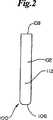
本発明の動力学的生体内吸収性ファスナー100の好ましい実施形態が図1〜図3に描かれる。一般にファスナー100は、図5にもそれぞれ描かれる肩部分103および105において共通のバックスパン106に操作可能に結合した一対のアーム102、104を含む。アーム102、104は丸みを帯びた先端108、110を含むのが好ましい。ファスナー100はさらにアーチ形の外側周囲表面112およびアーチ形内側表面114によって輪郭づけられる。内側表面114のアーチ形はステープルの荷重力を均し、集中するために機能し、組織内に置かれたファスナー100の潜在的揺動を減らす。最も一般的にはファスナー100はバックスパン106を切った場合、概ね円形の横断面を有し、それは徐々に細くなってむしろ矩形横断面に近づく。成形品の取り出しを容易にするために、ファスナー100は図3および図29に例として示すように複数の個別のセグメントおよび面を含むことができる。 A preferred embodiment of the kinetic
肘領域115、117の各先端108、110から丸みを帯びたクリート116、118が出ている。図4により明確に描かれるように、クリート116、118は外側に面するクリート表面122、内側に面するクリート表面124および丸みを帯びたクリート先端126によって輪郭づけられる。内側に面するクリート表面124はクリート基部128で内側表面114に連結し、持久的組織保持領域129を輪郭づける。アーム102、104およびバックスパン106に沿った内面114が内側に面するクリート表面124と一緒になって初期組織捕獲領域130を輪郭づける。
ファスナー100の設計要素が図5に詳しく描かれる。これらの設計要素は有効アーム中心線132、有効バックスパン中心線134、および有効クリート中心線136を含む。有効アーム中心線132、有効バックスパン中心線134および有効クリート中心線136について言えば、中心線とは概して周囲表面112および内面114の間の相対的等距離の線または外側に面するクリート表面122および内側に面するクリート表面124との間の相対的等距離の線を言う。ファスナー100がアーチ形の性質であるために、このような中心線は近似的なものに過ぎない。有効アーム中心線132および有効バックスパン中心線134の交点はファスナー100に対する肩内角138を作り出す。肩領域103、105は肩角138に近い領域と定義される。有効アーム中心線132と有効クリート中心線136の交点はファスナー100に対して肘内角142を作り出す。肘領域115、117は肘角142に近い領域と定義される。その他の設計要素はバックスパン巾146、アーム巾147、アーム長さ148、クリート長さ150、クリート先端長さ152、クリート先端126、対クリート先端距離154および先端対先端距離156を含む。 The design elements of the
本発明の説明の目的のためのファスナー100は、体内で少なくとも5ないし21日間、最適には、最終的に人体内で完全に吸収されるまで少なくとも14日間は、有効保持強度を維持するように選択される概ね生体内吸収性のポリマーからなる。最も好ましくは、生体内吸収性ポリマーは63%ポリ乳酸および37%ポリグリコリドからなる、一般的にはPLGAと呼ばれる混合生体内吸収性コポリマー類である。PLGAコポリマーは好ましい実施形態に使用されるが、その他の生体内吸収性ポリマー、例えばポリ乳酸、ポリグリコリドおよびポリカプロラクトンなどを、単体として、吸収特性、射出成型特性およびポリマークリープ特性など類似の特性を有するブレンドとしてまたはコポリマーとして使用することもできる。その他のポリマーと同様に、好ましい実施形態に使用されるPLGAコポリマーは粘弾性をあらわし、応力下でからみ合った分子が互いにすべり合う傾向がある粘弾性クリープを生ずる。 The
生体内吸収性ポリマー樹脂の費用が高いため、成形過程における不必要な廃棄を避けるのが好ましい。廃棄物を減らすために、ファスナー100はマイクロモールディング射出成型法を使用して形成するのが好ましい。マイクロモールディング射出成形は、成形射出能力が1g未満である場合に使用するのが一般的である。適したマイクロモールディング射出装置、例えばバッテンフィールド・マイクロシステム(Battenfield Microsystem)50を使用して、本発明によるファスナー100の製造中の樹脂廃棄物を著しく減らすことができる。それに加えて、マイクロモールディング射出装置はその他の加工上の長所、例えば寸法安定性を高めるための高速射出、高温における低い滞留時間、および一体型部品処理能力などを有する。 Because of the high cost of bioabsorbable polymer resins, it is preferable to avoid unnecessary disposal in the molding process. To reduce waste, the
治癒過程中創傷閉鎖を維持する目的で、ファスナー100は創傷長さ1センチメートルあたり1.2lbfより大きい最小乾燥初期閉鎖強度を提供するように設計される。表皮下創傷閉鎖に使用される好ましい実施形態において、乾燥初期閉鎖強度は持久的組織保持領域129間を横方向に測定した場合ファスナー100あたり1.2lbfの最小ファスナー強度に相当する。創傷長さ1センチメートルあたり乾燥初期閉鎖強度1.2lbfを得る一つの方法は、ファスナー100に存在する生体内吸収性ポリマーの量を現在のファスナー設計に比べて増やすことである。ファスナー100の実施形態において、付加的ポリマーをアーム102、104の両方およびバックスパン106に比例的に付加して、ファスナー100の強度を最適化する。この実施形態において、ポリマーを比例的に追加すると、例えばバックスパン106に沿った、および肩領域140、アーム102、104または肘領域144におけるファスナー100の弱さは克服される。このような弱さは結局はファスナー100の破損に通ずる。ファスナー100のこの実施形態において、アーチ形周囲表面112とアーチ形内面114との組み合わせは、組織によって加えられる横方向の力を肩領域103、105に沿って分配する。バックスパン巾146およびアーム巾147を比例的に増加させることによって、ファスナー100は破損することなく横方向の力の集中に適応できる。このような設計は高価な生体内吸収性ポリマーの使用を最適化し、それによって乾燥初期強度の目標に達成するために不必要な廃棄物および費用を排除することができる。In order to maintain the healing process in wound closure, the
皮膚創傷158を閉鎖するために皮膚組織を表皮下で両側固定する際のファスナー100の好ましい使用が図6および図7、並びに“両側組織固定のための機械的方法および装置”と題する米国特許出願第10/179,628号および、やはり“両側組織固定のための機械的方法および装置”と題する分割出願である米国特許出願第10/448,838号に記載されている。これらは両方とも本発明の譲受人に一般的に譲渡され、参考としてそのまま本明細書に組み込まれる。皮膚創傷158は概して、ギャップ164によって分離される一対の対置する皮膚表面160、162からなる。ギャップ164は外科的切開のような意図的手段、または偶発的切り傷のような事故的手段によって生じる。対置する各皮膚表面160、162は明確な3層を含む:表皮層または表皮166;真皮層または真皮168;表皮下層170。表皮166は生物学的治癒過程を妨害する可能性があり、治癒過程には役立たない死んだ皮膚組織からなる。表皮下層170は一般的に生物学的治癒過程全体を通じて皮膚閉鎖ファスナーをつなぎ止め保持するために必要な強度に欠ける脂肪組織の層を含む。一般的に医師は、対置する皮膚表面160、162の真皮168を力によって近づけるというやり方で皮膚創傷158を閉鎖する。真皮168は生きている組織からなるので、接合すると皮膚創傷158の生物学的治癒が直ちに始まり、接合の最初の24時間以内に限定的治癒が起きる。さらに、真皮168はファスナー100をつなぎ止め、保持し、保有するのに十分な強度および弾性を有する。 A preferred use of
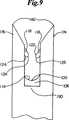
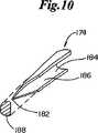
図8、図9、図10および図11に概略示すように、1対の穿孔メンバ174、176を組み込んだ送達具172を使用してファスナー100を創傷158に導入する。最も一般的には、送達具172はハンドル177および、アプリケータヘッド180に結合したトリガーアセンブリ178を含む。トリガーアセンブリは穿孔メンバ174、176を進めたり引っ込めたりする。穿孔メンバ174、176は組織を穿孔するための尖った先端182と、創傷158と接し、創傷158にファスナー100を運び込むための保持空間186を形成する半円形断面184とを含む。断面184は最大穿孔巾188を決める。穿孔メンバ174、176はバックスパンメンバ190と結合している。アプリケータヘッド180はガイドメンバ192、1対の捕獲領域194、196、1対の圧縮メンバ198、200および1対の孔202、204も含むことができる。 The
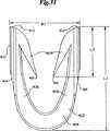
ファスナー100の好ましい使用において、創傷158に存在する皮膚組織の表皮下両側固定は、同時に出願された“両側組織固定のための機械的方法および装置”と題する米国特許出願に記載される徹底両側組織固定法を用いて実現する。この特許は、そのコピーが添付された本発明の譲受人に普通譲渡され、その開示は参考としてそのまま本明細書に組み込まれる。例えば図8に示されるこの両側組織固定技術において、ファスナー100は穿孔メンバ174、176およびバックスパンメンバ190の間に装填される。断面184は、クリート116、118だけが横断面184から内側に突き出るように、外側表面112にきちっと合うように設計される。ひとたびファスナー100が装填されると、ガイドメンバ192が皮膚創傷158内に入れられる。圧縮メンバ198、200を使用して対置する皮膚表面160、162を近づけ、それらを捕獲領域194、196内に押し付ける。圧縮メンバ198、200は力で皮膚創傷158を図12に示すようにめくれた位置206にする。送達具172は、ガイドメンバ192の方向変更、圧縮メンバ198、200の送達具172への組み込み、および送達具172がマルチ−ショット設計のための保存および装填手段を含む設計など、種々の実施形態で使用できることは明らかである。 In a preferred use of the
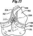
捕獲領域194、196の正確な位置決めによって、対置する皮膚表面160、162の真皮168に明確にされる1対の標的組織領域208、210は図15に描かれているように穿孔メンバ174、176の先端182に存在する。トリガーアセンブリ178を用い、穿孔メンバ174、176を捕獲領域194、196内にまで進め、標的組織領域208、210を通って、真皮層168に開けられる開口にまで進める。先端182は標的組織領域208、210から進み続け、図13に示すようにガイドメンバ192にある孔202、204へと進む。穿孔メンバ174、176が進むにつれて、ファスナー100も同時に標的組織領域208、210の中に進入する。図14に示されるように、クリート116のそして同様にクリート118の外側に面するクリート表面122が、最大挿入巾212を決める。この最大挿入巾は穿孔メンバ174、176の最大穿孔巾188より大きくなるように意図的に設計され、製造される。したがって、穿孔メンバ174、176の先端182によって真皮168に開けられる開口は最大挿入巾212に合うように伸びなければならない。クリート116、118が孔202、204内に進むにつれて、真皮168はクリート116、118の先端126の通過で弾力的に伸ばされる。真皮168はその後元に戻り、クリート基部128の周囲位置にそして持久的組織保持領域129に弾力的にピッタリと締まる。 By precise positioning of the
トリガーアセンブリ178を使用し、穿孔メンバ174、176は孔202、204、標的組織領域208、210および捕獲領域194、196から順次引き出される。しかしファスナー100は標的組織領域208、210内に留まる。なぜならばクリート116、118、持久的組織保持領域129および特にクリート基部128が共同して、捕獲した真皮168を保持し、ファスナー100が引き抜かれないようにするからである。バックスパン106はギャップ164を横切り、対置する皮膚表面160、162、および特に真皮168を強制的に近づけ、生物学的治癒過程が促進されるようにする。一般的に徹底挿入法は皮膚創傷158の長さに沿って反復され、複数のファスナー100が共同して皮膚創傷158を図16に示すように強制的に閉鎖する。複数のファスナー100の使用によって、皮膚創傷158に沿う複数のファスナー100の間の距離を減らすことによって、創傷長さ1センチメートルあたりの最小乾燥初期閉鎖強度は一般的な値1.2lbfを超えることができる。相応じて、複数のファスナー100の使用により、ファスナー100をその他の創傷閉鎖用途のためにまたは体内の別の部位のために適切な大きさにし、設計することができる。好ましい実施形態において、ファスナー100は、皮膚表面に対して概ね平行になるように皮膚創傷内に置かれる。Using
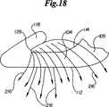
徹底法によって創傷158内に挿入されたファスナー100が図17に示される。創傷閉鎖の前および直後に、ファスナー100は初期組織捕獲領域130を有する第一の位置212に存在する。第一の位置212に存在する際、肩角138は90゜より若干大きい。その一方で肘角142は90゜より実質的に小さく、約25゜が最も好ましい。第一位置212は挿入時のファスナー100をあらわし、本明細書ではT1として示される。好ましい実施形態において、ファスナー100は図5および図17に描かれる中心軸214の回りに対称である。しかし別の実施形態は例えば変化したアーム長さ148、クリート長さ150、バックスパン巾146、異なる肩角138および肘角142など、非対称的設計を含むことができる。ファスナー100は、第一対置側160および第二対置側162において等しい量が組織捕獲領域130内に保持されるように置かれるのが好ましい。ファスナー100の創傷158への徹底挿入後、図18に示すようにファスナー100は一連の横方向の力216にさらされる。横方向の力216は、ファスナー100の最初の装填後しばらくの間、クリート基部128から肩領域103、105まで、内面114に沿って作用する。 The
横方向の力216にさらされた際にファスナー100の破損を防止するために、ファスナー100は治癒期間中重合体クリープを有するように特に選択された生体内吸収性ポリマーから作られる。横方向の力216の総計がファスナー100の最小乾燥初期閉鎖強度を超える場合、ファスナー100は直ちに再形成し始める。ファスナー100がひとたび創傷158内に置かれると、体温と体湿度の組み合わせによって、ファスナー100に使用されている生体内吸収性ポリマーは軟化、そして分解し始め、それにつれてファスナー100の閉鎖強度は低下し始める。横方向の力216の総計が最初はファスナー100の最大乾燥初期閉鎖強度を超えないとはいえ、生体内吸収性ポリマーの分解が、創傷閉鎖に続くある時期T2にファスナー100を再形成させるのが普通である。 To prevent breakage of the
図19には、ファスナー閉鎖強度より大きい横方向の力216にさらされた後の半分開いた位置218のファスナー100が描かれる。ファスナーを置く位置および創傷部位によっては挿入後直ちに再形成が起こることもあるが、ファスナー100は挿入後少なくとも24時間のT2期間までは半分開いた位置218に再形成しないのが好ましい。描かれるように、ファスナー閉鎖強度を超える横方向の力216は主として肩領域103、105および、より小さい程度ではあるが肘領域115、117の両方に重合体クリープを起こす。しかし、ファスナー100は耐え続け、クリート基部128周囲および持久的組織保持領域129内に弾力的真皮を持続的に保持することによって、捕獲した組織を近づけ続ける。 FIG. 19 depicts the
図20および図21には、半分開いた位置218まで再形成するのに必要な力を超える横方向の力216にさらされた後のほとんど開いた位置220のファスナー100が描かれる。ファスナー100は、置き方および創傷の位置によって挿入後直ちに再形成が起きることもあるが、挿入から少なくとも1ないし14日間、最適には少なくとも7日間のT2期間までは、ほとんど開いた位置220にまで再形成しないのが好ましい。ファスナー100は肩領域103、105および肘領域115、117における重合体クリープによっても再形成する。なお、ファスナー100の閉鎖強度は時が経つにつれて生体内吸収ポリマーの人体による破壊によって減少する。それとは別に、最初はファスナー100の再形成を引き起こすには不十分であった横方向の力216は、ファスナー100を創傷158に置いた後しばらくすると少なくともある程度のファスナー再形成を引き起こす可能性がある。ほとんど開いた位置220において、治癒過程中は、弾力的真皮がクリート基部128内に保持され続けるために、捕獲組織は接近したままである。一般的にクリート基部128は、生体内吸収性ポリマーが吸収され、アーム102、104またはバックスパン106の破壊などの失敗が起きる時点、または肘領域115、177の重合体クリープが肘角142を90゜より大きく開き、弾力性真皮168がクリート128から滑り出る時点までは、弾力性真皮を保持し続ける。ほとんど開いた位置220では、肩角138は徐々に判別困難となり、その代わりに、バックスパン106の中心点と各持久的組織保持領域の先端129とによって輪郭づけられる内部ミッドスパン角221が形成される。図22に記載されるような真皮組織の表皮下両側結合の好ましい実施形態において、挿入後ほとんど開いた位置220まで再形成した1対のファスナー100は創傷158を接合し続ける。クリート基部128内に真皮168を持続的に捕獲することにより、創傷158は治癒期間中、一般的には21日までは閉鎖したままである。再形成過程中、肘角142とミッドスパン角との合計は360゜未満に留まり、ファスナー100は捕獲した組織を最短分解期間より長く持続的に保持することができる。T3としてあらわされる最短分解期間の後、ファスナー100はアーム102、104、クリート116、118またはバックスパン106の破損による失敗を受けやすくなる。 20 and 21 depict the
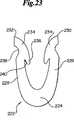
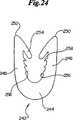
ファスナー100の好ましい実施形態およびその使用法を説明したが、同じ動力学的再形成特性を特徴とするその他の種々のステープル構造並びに徹底挿入法が利用できる。例えば図23、図24および図25は追加的保持要素を組み込み、さらに創傷閉鎖を促進する別のファスナー設計を示す。図23によると、ファスナー222はバックスパン224およびアーム226、228からなる。アーム226、228は先端230、232を含み、それら先端は内部クリート236および外部凹み238を含むハンマー状の頭部234の形状を有する。内部クリート236は、徹底挿入法によって弾力性組織を同様に捕獲するクリート基部240を含む。図24により、ファスナー242はバックスパン244およびアーム246、248からなる。アーム246、248は先端250、252を含み、徹底法を使用して同様に弾力性組織を掴む内部クリート254を含む。それに加えて、アーム246、248は一連の内部突起256を含み、ファスナー242が捕獲された組織による横方向の力に応えて再形成する際に、捕獲された組織の保持をさらに助ける。図25によると、ファスナー258はバックスパン260およびアーム262、264からなる。アーム262、264は、内部クリート270を有する先端266、268を含み、徹底法によって同様に弾力性組織を掴む。それに加えて、バックスパン260は1対の対置する突起272、274を含み、ファスナー258が捕獲された組織による横方向の力に応えて再形成する際に、捕獲された組織の保持をさらに助ける。本発明のファスナーを、2本だけのアームによって単一平面内で形成される初期組織捕獲領域を参照して記載したが、複数のアームを取り付けることもでき、複数の面が例えばバックスパンの中心点に角度をもって組織捕獲領域のために役立てることもできる。 While a preferred embodiment of the
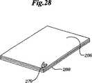
本発明のファスナーのまた別の実施形態が図26に示される。ファスナー276は少なくとも2つの個別の生体内吸収層を使用する設計を有する、前記のファスナーに代わる任意のファスナー構造からなることができる。図示されるように、ファスナー276は第一の生体内吸収層278、第二の生体内吸収層280および第三の生体内吸収層282を含む。この実施形態は異なる生体内吸収性材料の平面的配置を示しているが、型に沿って複数の注入部位を用いて例えば肩および肘領域が異なるポリマー材で形成された同様な構造を実現できることは理解できる。実際、ファスナー276は接着剤、加熱または成形法によって形成でき、その際それらの層は既述のマイクロモールディング法を使用して、または図27に示すような押出し法284によって別々に製造した後に接着される。また別の製法においては、図28に示すように、複数の生体内吸収層288からなるシート286からファスナー276を打ち抜くかまたは切り取ることができる。複数の生体内吸収層288を有するファスナー276は、より速く分解する生体内吸収ポリマーとより緩徐に分解する生体内分解ポリマーとを混合し、合わせることができるなどの設計的利点を多数有する。それに加えて、抗生物質、凝固剤のような薬または医薬品もしくは遺伝子治療剤でも層間または領域間に組み込むことによって、ファスナー276は送達具として使用され、それらの層が体内で分解する際に、またはそのファスナーの外側表面上にも放出され、治癒過程を促進する。 Another embodiment of the fastener of the present invention is shown in FIG. The
ファスナー290のまた別の実施形態が図29に描かれる。ファスナー290はバックスパン292およびアーム294、296からなる。ファスナー290はバックスパン292およびアーム294、296を通じて概ね一貫した厚さ297を有する。アーム294、296はさらに先端298、300を含み、各先端298、300はクリート基部304を有する内部クリート302を有する。アーム294、296と内部クリート302およびクリート基部304との組み合わせが持久的組織保持領域306を輪郭づけ、既述のように徹底挿入法を使用して弾力性組織を掴む。 Another embodiment of a
図30および図31には、本発明のファスナー400のより初期の実施形態が示される。ファスナー400は体部402を有し、それは1対のフォークメンバまたは脚402を結合するクロス−メンバ408を含む。各脚406の外側縁410は穿孔メンバ174、176の保持空間186に合う大きさおよび形状を有し、ファスナー400は穿孔メンバ174、176間にぴったり合い、滑り込むことができる。肩414はバックスパンメンバ190の固体円筒状断面にかみ合うように取り付けられるのが好ましい。これによってファスナー400を穿孔メンバ174、176の動きと共に遠くまで進めることができる。各脚406の遠位端412は湾曲した形を有し、穿孔メンバ174、176によって作り出される、スカイブと呼ばれる皮膚開口を容易に通過できる。好ましくは内側に向いたバーブ404が各脚406上に作られ、ひとたび装着されたファスナーが引き抜かれないようにする。 30 and 31 show an earlier embodiment of the fastener 400 of the present invention. The fastener 400 has a
ファスナー400では図30および図31に示すように全体的U字型が好ましいとはいえ、両側組織をかみ合わせる能力を有するその他の形も可能であり、本発明の範囲内である。このようなその他の形には、例えば非制限的に、普通のステープルに似た四角形、半円形、またはC字型またはV字型またはW字型などがあり、この際クロスメンバ408は曲がり、またはその他の特徴を有する。ファスナー400の形が一般に平面構造であるが、その他の非平面的形および構造、例えば各脚406に複数の突起を有し、その各突起が異なる面に配置されているファスナー、またはファスナー400の通常の面から突き出てV字型に配列したクロスメンバ408を有するファスナーなどを使用できることが理解される。2つの脚メンバ406が好ましいが、付加的脚メンバ406をファスナー400の同じ面または異なる面に加え、ファスナーの各側の脚メンバが例えば二叉(dident)または三叉(trident)構造も形成できることが理解される。 Although a generally U-shaped fastener 400 is preferred for the fastener 400 as shown in FIGS. 30 and 31, other shapes capable of interlocking bilateral tissue are possible and within the scope of the present invention. Such other shapes include, but are not limited to, square, semi-circle, or C-shaped or V-shaped or W-shaped similar to ordinary staples, where the
図32に示すように、内部横断面領域409は圧縮された真皮組織を捕獲するファスナー400によって決まる。好ましい実施形態において、内部横断面領域409は1.5sq.mmないし50sq.mmであり、最も好ましくは約5sq.mmないし10sq.mmである。この領域は通常、内径の長さ1.5mmないし9mm、最も好ましくは約3.8mmと、内径巾1mmないし5mm、最も好ましくは約2mmとによって決まる。横断面領域409の形および配置として多数の形および構造が使用できることは当然である。内部横断面領域409は、バーブ412の配置の結果、概ね矢じり状であることが好ましい。記載されるように、バーブ412または同様な逆行防止突起がファスナー400の引き抜きに対して抵抗する。バーブ412は内部横断面領域409内に配置されるのが好ましいが、バーブ412は省略されてもよいし、外側につけてもよい。 As shown in FIG. 32, the internal cross-sectional area 409 is determined by a fastener 400 that captures the compressed dermal tissue. In a preferred embodiment, the internal cross-sectional area 409 is 1.5 sq. mm to 50 sq. mm, most preferably about 5 sq. mm to 10 sq. mm. This region is typically determined by an inner diameter length of 1.5 mm to 9 mm, most preferably about 3.8 mm, and an inner diameter width of 1 mm to 5 mm, most preferably about 2 mm. Of course, many shapes and configurations can be used as the shape and arrangement of the cross-sectional area 409. The internal cross-sectional area 409 is preferably generally arrowhead-shaped as a result of the arrangement of the
ファスナー400がデリバリーおよび適用中に再形成することはあり得るが、横断面領域409内に保持された真皮組織の大部分が十分硬いファスナー400によって圧縮された状態で捕獲され、好ましくは少なくとも10日間は、横断面領域409の寸法的一体性がその設計面積の±30%以内に維持されるのが好ましい。ファスナー400の構造的一体性は少なくとも21日間維持されるのが最も好ましい。このやり方で、ファスナー400に捕獲された真皮組織は、生物学的治癒過程が起きるのに十分な期間、その治癒過程中にその真皮組織に張力がかかることなく、圧縮された状態で保持される。ファスナー400の大きさおよびアプリケータアセンブリ100の操作が協同して内部横断面領域409内の真皮組織の圧縮比を1より大きくすることが好ましい。上記圧縮比は面積比または巾の比として決定される。巾の場合、圧縮比は、静止時の真皮組織における垂直界面51に対するスカイブの位置をファスナー400によって保持された場合の垂直界面51に対するスカイブの位置によって割ることによって決定される大きさの比である。面積の場合、圧縮比は、静止時にファスナー400によって保持される真皮組織の面積を実際の横断面積409によって割った、真皮組織の面積比である。 Although the fastener 400 may reform during delivery and application, the majority of the dermal tissue retained in the cross-sectional area 409 is captured in a compressed state by the sufficiently rigid fastener 400, and preferably for at least 10 days Preferably, the dimensional integrity of the cross-sectional area 409 is maintained within ± 30% of its design area. Most preferably, the structural integrity of the fastener 400 is maintained for at least 21 days. In this manner, the dermal tissue captured by the fastener 400 is held in a compressed state for a period of time sufficient for the biological healing process to occur without tensioning the dermal tissue during the healing process. . Preferably, the size of the fastener 400 and the operation of the
或いは、生体内再吸収性または生体内吸収性ファスナーの変形が真皮組織の圧縮の少なくとも若干を分担し、それによって機械的組織マニピュレータの必要性が軽減しまたは排除される可能性がある場合は、本発明によって教示されるように組織標的領域に変形可能ファスナーによる両側組織固定を利用することができる。この実施形態において、生体再吸収性または生体吸収性ファスナーはアプリケータ装置によって変形され、真皮組織を適切に圧縮する。生体再吸収性または生体吸収性ファスナーの変形は多数の方法で実現できる。例えば、ファスナーにプレストレスを与えて開いた構造にし、アプリケータによる機械的補助、超音波、熱または光エネルギーの適用を伴って、または伴わずに上記ファスナーの形状を現場で変化させてまたは圧力を弛緩させて閉鎖構造に戻す;適切な形状を有するポリマー材料、および装着時にこの材料が破壊されずに変形できるという組成物を設計する;またはこれらの技術の任意の組み合わせなどがある。 Alternatively, if the bioresorbable or bioabsorbable fastener deformation shares at least some of the compression of the dermal tissue, which may reduce or eliminate the need for a mechanical tissue manipulator, Bilateral tissue fixation with deformable fasteners can be utilized in the tissue target area as taught by the present invention. In this embodiment, the bioresorbable or bioabsorbable fastener is deformed by the applicator device to properly compress the dermal tissue. Deformation of the bioresorbable or bioabsorbable fastener can be achieved in a number of ways. For example, pre-stress the fasteners into an open structure and change the shape of the fasteners in the field with or without mechanical assistance by an applicator, application of ultrasound, heat or light energy or pressure The polymer material having an appropriate shape and a composition that can be deformed without breaking when worn; or any combination of these techniques.
ファスナー400は任意の適切な生体内分解性材料から形成されるのが好ましい。現在最も好ましい生体内分解性材料はラクチド/グリコリド・コポリマーである。このポリマーにおいて一構成成分はもう一つの構成成分の少なくとも10%未満になってはならず、ラクチドが60%〜70%の範囲であるのが好ましい。その他の適切な材料の例にはポリ(dl−ラクチド)、ポリ(l−ラクチド)、ポリグリコリド、ポリ(ジオキサノン)、ポリ(グリコリド−コ−トリメチレン・カルボネート)、ポリ(l−ラクチド−コ−グリコリド)、ポリ(dl−ラクチド−コ−グリコリド)、ポリ(l−ラクチド−コ−dl−ラクチド)およびポリ(グリコリド−コ−トリメチレン・カルボネート−コ−ジオキサノン)がある。さらに、その他の適切な物質には例えばコラーゲンおよびエラスチンなどの天然発生性生体ポリマー類、またはステンレス鋼、金属、ナイロンを含む組成物類、または非吸収性ファスナーの場合のその他の任意の生体適合性材料、またはファスナーの所望の用途および性能によって、そのような材料の種々の組み合わせもある。 The fastener 400 is preferably formed from any suitable biodegradable material. The presently most preferred biodegradable material is a lactide / glycolide copolymer. In this polymer, one component should not be less than at least 10% of the other component and preferably the lactide is in the range of 60% to 70%. Examples of other suitable materials include poly (dl-lactide), poly (l-lactide), polyglycolide, poly (dioxanone), poly (glycolide-co-trimethylene carbonate), poly (l-lactide-co- Glycolide), poly (dl-lactide-co-glycolide), poly (l-lactide-co-dl-lactide) and poly (glycolide-co-trimethylene carbonate-co-dioxanone). In addition, other suitable materials include naturally occurring biopolymers such as collagen and elastin, or compositions including stainless steel, metal, nylon, or any other biocompatible in the case of non-absorbable fasteners. There are various combinations of such materials, depending on the material, or the desired use and performance of the fastener.
本発明の動力学的生体内吸収性ファスナーの好ましい実施形態を記載したが、本発明によるファスナーは本発明の範囲および精神から逸脱することなく多数のその他の実施形態が可能であることは当業者には明らかである。 While preferred embodiments of the kinetic bioabsorbable fastener of the present invention have been described, those skilled in the art will appreciate that numerous other embodiments of the fastener according to the present invention are possible without departing from the scope and spirit of the present invention. Is obvious.
Claims (12)
Translated fromJapanese生体内吸収性ポリマー材料からなるファスナー体部からなり、前記ファスナー体部は前記ファスナー体部の内側の初期組織捕獲領域を輪郭づけ、前記ファスナー体部は:
各ファスナーアームが前記穿孔開口の1つに挿入可能である1対のファスナーアームと;
肘領域において各ファスナーアームに結合し、前記初期組織捕獲領域に後方に突き出しているクリートであって、前記クリートとファスナーアームとの間に肘内角を形成する前記クリートと;
前記クリートとファスナーアームとの間に形成され、前記肘領域に先端を有する各ファスナーアームの持久的組織保持領域と;
前記クリートの最外部表面と前記ファスナーアームの最外部表面との間の各ファスナーアームの最大挿入巾と;
肩領域で各ファスナーアームに結合するバックスパンであって、それぞれの肩内角が前記バックスパンと各ファスナーアームとの間に形成され、ミッドスパン内角がバックスパンの中心点と各持久的組織保持領域の先端との間に形成される前記バックスパンとを含んでなり、
前記肘領域および各ファスナーアームの肘内角は、最大挿入巾が対応する穿孔開口の巾より大きくなるように構成され、前記穿孔開口周囲の組織の少なくとも一部分が前記クリート上に引き伸ばされ、前記生体内吸収性ポリマー材料の最短分解期間より長く前記持久的組織保持領域内に弾力的に保持され、
前記肩領域および肩内角は前記ファスナーの装着中、創傷組織を前記初期組織捕獲領域内に捕獲し、装着後前記創傷組織によってかかる横方向応力に応えて動力学的に変形し、その際前記肘内角とミッドスパン内角の合計が360度未満に留まり、前記生体内吸収性ポリマー材料の前記最短分解期間までは前記生体内吸収材料の破損による失敗が起きない生体内吸収性ファスナー。A bioabsorbable fastener for insertion into a perforation openinginside askin wound,
It comprises a fastener body portion made of abioabsorbable polymer material , the fastener body portion outlines an initial tissue capture region inside the fastener body portion, and the fastener body portion includes:
A pair of fastener arms, each fastener arm being insertable into one of the perforated openings;
A cleatcoupled to each fastener armin the elbowregion and projecting rearwardly to the initial tissue capture region, the cleat forming an elbow internal angle between the cleat and the fastener arm;
A permanent tissue retention region of each fastener arm formed between the cleat and the fastener arm and having a tip in the elbowregion ;
The maximum insertion width of each fastener arm between the outermost surface of the cleat and the outermost surface of the fastener arm;
Backspanscoupled to each fastener arm at a shoulderregion , each shoulder internal angle being formed between said backspan and each fastener arm, and a midspan internal angle being the center point of each backspan and each permanent tissue holding region The backspan formed between the tip of the
The elbowarea and the elbow internal angle of each fastener arm are configured such that the maximum insertion width is greater than the width of the corresponding perforation opening, and at least a portion of the tissue around the perforation opening is stretched over the cleat, Elastically retained in the permanent tissue retention region for longer than the shortest degradation period of the absorbent polymer material;
The shoulderregion and the shoulder angle capture the wound tissue in the initial tissue capture region during attachment of the fastener, and dynamically deform in response to lateral stress applied by the wound tissue after attachment, wherein the elbow Abioabsorbable fastener in which the total of the inner angle and the midspan inner angle remains less than 360 degrees, and failure due to breakage of the bioabsorbable material does not occur until the shortest decomposition period of the bioabsorbable polymer material.
前記ステープルは実質的に生体内吸収性ポリマーからなるステープル体部からなり、前記ステープル体部は:
各々が遠位端および近位肩部分を有する1対のステープルアームと;
前記肩領域に近い前記1対のステープルアームを連結するバックスパンと;
前記創傷の対置する両側によって自然にかかる横方向の力に応じて破損することなく、最初の挿入位置から第二の変形位置まで変形するように構成された各肩領域;および
前記バックスパンに対して操作可能に角度を形成し、前記ステープルアームが前記第一挿入位置および第二変形位置の両方の位置にある場合、前記クリートとステープルアームとの間に組織を効果的に保持する組織保持領域を輪郭づける、前記ステープルアームの遠位端の近くにクリートを有する各ステープルアームとを含んでなる前記動力学的生体内吸収性ステープル。A kineticthe shape change bioabsorbable staples for use in wound of a living tissue having side surfaces opposing:
The staple comprises a staple body portion substantially made of a bioabsorbable polymer, wherein the staple body portion is:
A pair of staple arms, each having a distal end and a proximal shoulder portion;
A backspan connecting the pair of staple arms near the shoulderregion ;
Each shoulderregion configured to deform from an initial insertion position to a second deformation position without damaging in response to a lateral force naturally applied by opposite sides of the wound; and A tissue holding region that effectively holds the tissue between the cleat and the staple arm when the staple arm is operatively angled and the staple arm is in both the first insertion position and the second deformation position. Said kinetic bioabsorbable staple comprising: each staple arm having a cleat near a distal end of said staple arm.
肩領域でバックスパンによって結合した1対のステープルアームを含むステープル体部において、各アームはさらに内側に突き出たクリートを有する肘領域、前記ステープルアーム、前記内側に突き出たクリートおよび内部組織捕獲領域を輪郭づけている前記バックスパンを含む前記ステープル体部;および
前記バックスパンとステープルアームによって決まる肩内角を含む各肩領域において、前記肩内角は挿入時の第一位置では70゜〜100゜になるように作られ、挿入時に続く第二時点で前記肩内角は前記創傷の対置側面によって自然にかかる横方向の力に応えて、第二変形位置の120゜〜180゜に変化するように構成された各肩領域とを含む動力学的生体内吸収性ステープル。A kineticallychanging bioabsorbable staple for use in an in vivo tissue wound having opposing sides, comprising:
A staple body comprising a pair of staple armsjoined by a backspan at a shoulderregion , each arm further comprising an elbowregion having an inwardly projecting cleat, the staple arm, the inwardly projecting cleat and an internal tissue capture region. The staple body including the backspan contouring; and
In each shoulderregion including the shoulder internal angle determined by the backspan and the staple arm, the shoulder internal angle is formed to be 70 ° to 100 ° at the first position at the time of insertion, and the shoulder internal angle at a second time point that continues at the time of insertion. Is a kinetic bioabsorbable staple comprising each shoulderregion configured to change from 120 ° to 180 ° of the second deformation position in response to a lateral force naturally applied by the facing side of the wound .
実質的に生体内吸収性であるポリマーからなるステープル体部からなり、前記ステープル体部は:
遠位端および近位肩領域を各々有する1対のステープルアームにおいて、前記遠位端は内側に向いたクリートを含み、各クリートおよびアームが肘領域を形成する前記1対のステープルアーム;および
1対のステープルアームを肩領域の近くで連結するバックスパンを含み、
前記クリート、アームおよびバックスパンが協同して動力学的内部組織捕獲領域を形成し、前記内部捕獲領域は挿入時に第一の形を示し、前記肘領域および肩領域は皮膚創傷の対置側面によってかかる横方向の力に応えて破損することなく動力学的に変化し、挿入後、および生体内吸収性ポリマーの最短分解期間の前に、前記内部捕獲領域が第二時点の第二の形を示す前記生体内吸収性皮下ステープル。A bioabsorbable subcutaneous staple,
The staple body is made of a polymer that is substantially bioabsorbable, the staple body being:
1. A pair of staple arms each having a distal end and a proximal shoulderregion , wherein the distal end includes an inwardly facing cleat, wherein each cleat and arm forms an elbowregion ; Including a backspan connecting the pair of staple arms near the shoulderregion ;
The cleat arms and the back span cooperate to form a dynamic internal tissue capture region, the inner capture region represents a first form upon insertion, the elbowregion and shoulderregion such by opposing sides of theskin wound Dynamically changes without breaking in response to lateral forces, and after insertion and before the shortest degradation period of the bioabsorbable polymer, the internal capture region exhibits a second shape at the second time point The bioabsorbable subcutaneous staple.
Applications Claiming Priority (2)
| Application Number | Priority Date | Filing Date | Title |
|---|---|---|---|
| US10/179,628US6726705B2 (en) | 2002-06-25 | 2002-06-25 | Mechanical method and apparatus for bilateral tissue fastening |
| PCT/US2003/020083WO2004000105A2 (en) | 2002-06-25 | 2003-06-25 | Dynamic bioabsorbable fastener for use in wound closure |
Publications (2)
| Publication Number | Publication Date |
|---|---|
| JP2005530567A JP2005530567A (en) | 2005-10-13 |
| JP4437317B2true JP4437317B2 (en) | 2010-03-24 |
Family
ID=29734939
Family Applications (2)
| Application Number | Title | Priority Date | Filing Date |
|---|---|---|---|
| JP2004516263AExpired - LifetimeJP4437317B2 (en) | 2002-06-25 | 2003-06-25 | Bioabsorbable fasteners for use in wound closure |
| JP2004516211AExpired - LifetimeJP4786902B2 (en) | 2002-06-25 | 2003-06-25 | Mechanical method and instrument for bilateral tissue fixation |
Family Applications After (1)
| Application Number | Title | Priority Date | Filing Date |
|---|---|---|---|
| JP2004516211AExpired - LifetimeJP4786902B2 (en) | 2002-06-25 | 2003-06-25 | Mechanical method and instrument for bilateral tissue fixation |
Country Status (5)
| Country | Link |
|---|---|
| US (3) | US6726705B2 (en) |
| EP (2) | EP1531736B1 (en) |
| JP (2) | JP4437317B2 (en) |
| AU (2) | AU2003279285A1 (en) |
| WO (2) | WO2004000104A2 (en) |
Cited By (2)
| Publication number | Priority date | Publication date | Assignee | Title |
|---|---|---|---|---|
| US10045777B2 (en) | 2013-01-31 | 2018-08-14 | Opus Ksd Inc. | Delivering bioabsorbable fasteners |
| US10441278B2 (en) | 2006-07-01 | 2019-10-15 | Opus Ksd Inc. | Deploying fasteners |
Families Citing this family (485)
| Publication number | Priority date | Publication date | Assignee | Title |
|---|---|---|---|---|
| US6241747B1 (en) | 1993-05-03 | 2001-06-05 | Quill Medical, Inc. | Barbed Bodily tissue connector |
| US8795332B2 (en) | 2002-09-30 | 2014-08-05 | Ethicon, Inc. | Barbed sutures |
| US5931855A (en) | 1997-05-21 | 1999-08-03 | Frank Hoffman | Surgical methods using one-way suture |
| US7056331B2 (en) | 2001-06-29 | 2006-06-06 | Quill Medical, Inc. | Suture method |
| US6848152B2 (en) | 2001-08-31 | 2005-02-01 | Quill Medical, Inc. | Method of forming barbs on a suture and apparatus for performing same |
| US8074857B2 (en)* | 2002-06-25 | 2011-12-13 | Incisive Surgical, Inc. | Method and apparatus for tissue fastening with single translating trigger operation |
| US7112214B2 (en)* | 2002-06-25 | 2006-09-26 | Incisive Surgical, Inc. | Dynamic bioabsorbable fastener for use in wound closure |
| US6726705B2 (en)* | 2002-06-25 | 2004-04-27 | Incisive Surgical, Inc. | Mechanical method and apparatus for bilateral tissue fastening |
| US7950559B2 (en)* | 2002-06-25 | 2011-05-31 | Incisive Surgical, Inc. | Mechanical method and apparatus for bilateral tissue fastening |
| US20120145765A1 (en) | 2002-06-25 | 2012-06-14 | Peterson James A | Mechanical method and apparatus for bilateral tissue fastening |
| US6773450B2 (en) | 2002-08-09 | 2004-08-10 | Quill Medical, Inc. | Suture anchor and method |
| US20040088003A1 (en) | 2002-09-30 | 2004-05-06 | Leung Jeffrey C. | Barbed suture in combination with surgical needle |
| US8100940B2 (en) | 2002-09-30 | 2012-01-24 | Quill Medical, Inc. | Barb configurations for barbed sutures |
| US7343920B2 (en)* | 2002-12-20 | 2008-03-18 | Toby E Bruce | Connective tissue repair system |
| US7624487B2 (en) | 2003-05-13 | 2009-12-01 | Quill Medical, Inc. | Apparatus and method for forming barbs on a suture |
| US20070084897A1 (en) | 2003-05-20 | 2007-04-19 | Shelton Frederick E Iv | Articulating surgical stapling instrument incorporating a two-piece e-beam firing mechanism |
| US9060770B2 (en) | 2003-05-20 | 2015-06-23 | Ethicon Endo-Surgery, Inc. | Robotically-driven surgical instrument with E-beam driver |
| US10548592B2 (en) | 2004-05-14 | 2020-02-04 | Ethicon, Inc. | Suture methods and devices |
| US8215531B2 (en) | 2004-07-28 | 2012-07-10 | Ethicon Endo-Surgery, Inc. | Surgical stapling instrument having a medical substance dispenser |
| US9072535B2 (en) | 2011-05-27 | 2015-07-07 | Ethicon Endo-Surgery, Inc. | Surgical stapling instruments with rotatable staple deployment arrangements |
| US11890012B2 (en) | 2004-07-28 | 2024-02-06 | Cilag Gmbh International | Staple cartridge comprising cartridge body and attached support |
| US11998198B2 (en) | 2004-07-28 | 2024-06-04 | Cilag Gmbh International | Surgical stapling instrument incorporating a two-piece E-beam firing mechanism |
| US20060122635A1 (en)* | 2004-12-03 | 2006-06-08 | Naegeli Chad D | Storage system for bioabsorbable fasteners |
| US7682372B2 (en)* | 2004-12-22 | 2010-03-23 | Incisive Surgical, Inc. | Sequential tissue forceps for use in tissue fastening |
| IL166206A0 (en)* | 2005-01-09 | 2006-01-15 | Shifrin Edward G | Apparatus and method for delivery and oversew fixation of vascular grafts |
| US7438208B2 (en) | 2005-01-25 | 2008-10-21 | Entrigue Surgical, Inc. | Septal stapler apparatus |
| EP1848344A4 (en)* | 2005-02-04 | 2014-01-29 | Moshe Dudai | Staples, staplers, anastomosis devices, and methods for their applications |
| US8999289B2 (en) | 2005-03-22 | 2015-04-07 | President And Fellows Of Harvard College | Treatment of protein degradation disorders |
| WO2007013906A2 (en) | 2005-07-15 | 2007-02-01 | Incisive Surgical, Inc. | Mechanical method and apparatus for sequential tissue fastening |
| US7934630B2 (en) | 2005-08-31 | 2011-05-03 | Ethicon Endo-Surgery, Inc. | Staple cartridges for forming staples having differing formed staple heights |
| US11246590B2 (en) | 2005-08-31 | 2022-02-15 | Cilag Gmbh International | Staple cartridge including staple drivers having different unfired heights |
| US9237891B2 (en) | 2005-08-31 | 2016-01-19 | Ethicon Endo-Surgery, Inc. | Robotically-controlled surgical stapling devices that produce formed staples having different lengths |
| US7669746B2 (en) | 2005-08-31 | 2010-03-02 | Ethicon Endo-Surgery, Inc. | Staple cartridges for forming staples having differing formed staple heights |
| US10159482B2 (en) | 2005-08-31 | 2018-12-25 | Ethicon Llc | Fastener cartridge assembly comprising a fixed anvil and different staple heights |
| US11484312B2 (en) | 2005-08-31 | 2022-11-01 | Cilag Gmbh International | Staple cartridge comprising a staple driver arrangement |
| US20070106317A1 (en) | 2005-11-09 | 2007-05-10 | Shelton Frederick E Iv | Hydraulically and electrically actuated articulation joints for surgical instruments |
| US7753904B2 (en) | 2006-01-31 | 2010-07-13 | Ethicon Endo-Surgery, Inc. | Endoscopic surgical instrument with a handle that can articulate with respect to the shaft |
| US11278279B2 (en) | 2006-01-31 | 2022-03-22 | Cilag Gmbh International | Surgical instrument assembly |
| US11793518B2 (en) | 2006-01-31 | 2023-10-24 | Cilag Gmbh International | Powered surgical instruments with firing system lockout arrangements |
| US7845537B2 (en) | 2006-01-31 | 2010-12-07 | Ethicon Endo-Surgery, Inc. | Surgical instrument having recording capabilities |
| US8186555B2 (en) | 2006-01-31 | 2012-05-29 | Ethicon Endo-Surgery, Inc. | Motor-driven surgical cutting and fastening instrument with mechanical closure system |
| US20110295295A1 (en) | 2006-01-31 | 2011-12-01 | Ethicon Endo-Surgery, Inc. | Robotically-controlled surgical instrument having recording capabilities |
| US8820603B2 (en) | 2006-01-31 | 2014-09-02 | Ethicon Endo-Surgery, Inc. | Accessing data stored in a memory of a surgical instrument |
| US20120292367A1 (en) | 2006-01-31 | 2012-11-22 | Ethicon Endo-Surgery, Inc. | Robotically-controlled end effector |
| US8708213B2 (en) | 2006-01-31 | 2014-04-29 | Ethicon Endo-Surgery, Inc. | Surgical instrument having a feedback system |
| US11224427B2 (en) | 2006-01-31 | 2022-01-18 | Cilag Gmbh International | Surgical stapling system including a console and retraction assembly |
| US8992422B2 (en) | 2006-03-23 | 2015-03-31 | Ethicon Endo-Surgery, Inc. | Robotically-controlled endoscopic accessory channel |
| EP2015681B1 (en) | 2006-05-03 | 2018-03-28 | Datascope Corp. | Tissue closure device |
| US8304451B2 (en) | 2006-05-03 | 2012-11-06 | President And Fellows Of Harvard College | Histone deacetylase and tubulin deacetylase inhibitors |
| EP2023826B1 (en)* | 2006-05-12 | 2017-06-21 | ArthroCare Corporation | Middle turbinate medializer |
| US8322455B2 (en) | 2006-06-27 | 2012-12-04 | Ethicon Endo-Surgery, Inc. | Manually driven surgical cutting and fastening instrument |
| US10568652B2 (en) | 2006-09-29 | 2020-02-25 | Ethicon Llc | Surgical staples having attached drivers of different heights and stapling instruments for deploying the same |
| US11980366B2 (en) | 2006-10-03 | 2024-05-14 | Cilag Gmbh International | Surgical instrument |
| US11291441B2 (en) | 2007-01-10 | 2022-04-05 | Cilag Gmbh International | Surgical instrument with wireless communication between control unit and remote sensor |
| US8684253B2 (en) | 2007-01-10 | 2014-04-01 | Ethicon Endo-Surgery, Inc. | Surgical instrument with wireless communication between a control unit of a robotic system and remote sensor |
| US8632535B2 (en) | 2007-01-10 | 2014-01-21 | Ethicon Endo-Surgery, Inc. | Interlock and surgical instrument including same |
| US11039836B2 (en) | 2007-01-11 | 2021-06-22 | Cilag Gmbh International | Staple cartridge for use with a surgical stapling instrument |
| US20080169333A1 (en) | 2007-01-11 | 2008-07-17 | Shelton Frederick E | Surgical stapler end effector with tapered distal end |
| US20080215090A1 (en)* | 2007-02-14 | 2008-09-04 | Entrigue Surgical, Inc. | Method and System for Tissue Fastening |
| US7673782B2 (en) | 2007-03-15 | 2010-03-09 | Ethicon Endo-Surgery, Inc. | Surgical stapling instrument having a releasable buttress material |
| US20080249563A1 (en)* | 2007-04-04 | 2008-10-09 | Peterson James A | Method and apparatus for tissue fastening |
| US8915943B2 (en) | 2007-04-13 | 2014-12-23 | Ethicon, Inc. | Self-retaining systems for surgical procedures |
| US11564682B2 (en) | 2007-06-04 | 2023-01-31 | Cilag Gmbh International | Surgical stapler device |
| US8931682B2 (en) | 2007-06-04 | 2015-01-13 | Ethicon Endo-Surgery, Inc. | Robotically-controlled shaft based rotary drive systems for surgical instruments |
| US7753245B2 (en) | 2007-06-22 | 2010-07-13 | Ethicon Endo-Surgery, Inc. | Surgical stapling instruments |
| US11849941B2 (en) | 2007-06-29 | 2023-12-26 | Cilag Gmbh International | Staple cartridge having staple cavities extending at a transverse angle relative to a longitudinal cartridge axis |
| US9168039B1 (en) | 2007-09-06 | 2015-10-27 | Cardica, Inc. | Surgical stapler with staples of different sizes |
| US7988026B2 (en) | 2007-09-06 | 2011-08-02 | Cardica, Inc. | Endocutter with staple feed |
| US8403956B1 (en) | 2007-09-06 | 2013-03-26 | Cardica, Inc. | Multiple-use surgical stapler |
| US8070036B1 (en) | 2007-09-06 | 2011-12-06 | Cardica, Inc | True multi-fire surgical stapler configured to fire staples of different sizes |
| ES2398779T3 (en) | 2007-09-27 | 2013-03-21 | Ethicon Llc | Self-retaining sutures that include tissue retention elements with enhanced strength |
| US20090093824A1 (en)* | 2007-10-04 | 2009-04-09 | Hasan Jafar S | Wound closure fasteners and device for tissue approximation and fastener application |
| US8216571B2 (en) | 2007-10-22 | 2012-07-10 | Schering Corporation | Fully human anti-VEGF antibodies and methods of using |
| US8916077B1 (en) | 2007-12-19 | 2014-12-23 | Ethicon, Inc. | Self-retaining sutures with retainers formed from molten material |
| WO2009086172A2 (en) | 2007-12-19 | 2009-07-09 | Angiotech Pharmaceuticals, Inc. | Self-retaining sutures with heat-contact mediated retainers |
| US8118834B1 (en) | 2007-12-20 | 2012-02-21 | Angiotech Pharmaceuticals, Inc. | Composite self-retaining sutures and method |
| US8615856B1 (en) | 2008-01-30 | 2013-12-31 | Ethicon, Inc. | Apparatus and method for forming self-retaining sutures |
| US8875607B2 (en) | 2008-01-30 | 2014-11-04 | Ethicon, Inc. | Apparatus and method for forming self-retaining sutures |
| JP5410110B2 (en) | 2008-02-14 | 2014-02-05 | エシコン・エンド−サージェリィ・インコーポレイテッド | Surgical cutting / fixing instrument with RF electrode |
| US8636736B2 (en) | 2008-02-14 | 2014-01-28 | Ethicon Endo-Surgery, Inc. | Motorized surgical cutting and fastening instrument |
| US8573465B2 (en) | 2008-02-14 | 2013-11-05 | Ethicon Endo-Surgery, Inc. | Robotically-controlled surgical end effector system with rotary actuated closure systems |
| US7866527B2 (en) | 2008-02-14 | 2011-01-11 | Ethicon Endo-Surgery, Inc. | Surgical stapling apparatus with interlockable firing system |
| US11986183B2 (en) | 2008-02-14 | 2024-05-21 | Cilag Gmbh International | Surgical cutting and fastening instrument comprising a plurality of sensors to measure an electrical parameter |
| US9179912B2 (en) | 2008-02-14 | 2015-11-10 | Ethicon Endo-Surgery, Inc. | Robotically-controlled motorized surgical cutting and fastening instrument |
| US7819298B2 (en) | 2008-02-14 | 2010-10-26 | Ethicon Endo-Surgery, Inc. | Surgical stapling apparatus with control features operable with one hand |
| US9585657B2 (en) | 2008-02-15 | 2017-03-07 | Ethicon Endo-Surgery, Llc | Actuator for releasing a layer of material from a surgical end effector |
| ES2706295T3 (en) | 2008-02-21 | 2019-03-28 | Ethicon Llc | Method and apparatus for raising retainers in self-retaining sutures |
| US8216273B1 (en) | 2008-02-25 | 2012-07-10 | Ethicon, Inc. | Self-retainers with supporting structures on a suture |
| US8641732B1 (en) | 2008-02-26 | 2014-02-04 | Ethicon, Inc. | Self-retaining suture with variable dimension filament and method |
| SG188784A1 (en) | 2008-04-15 | 2013-04-30 | Ethicon Llc | Self-retaining sutures with bi-directional retainers or uni-directional retainers |
| US8961560B2 (en) | 2008-05-16 | 2015-02-24 | Ethicon, Inc. | Bidirectional self-retaining sutures with laser-marked and/or non-laser marked indicia and methods |
| CA2736756C (en) | 2008-09-17 | 2017-10-31 | Entrigue Surgical, Inc. | Methods and systems for medializing a turbinate |
| US9005230B2 (en) | 2008-09-23 | 2015-04-14 | Ethicon Endo-Surgery, Inc. | Motorized surgical instrument |
| US9386983B2 (en) | 2008-09-23 | 2016-07-12 | Ethicon Endo-Surgery, Llc | Robotically-controlled motorized surgical instrument |
| US8210411B2 (en) | 2008-09-23 | 2012-07-03 | Ethicon Endo-Surgery, Inc. | Motor-driven surgical cutting instrument |
| US11648005B2 (en) | 2008-09-23 | 2023-05-16 | Cilag Gmbh International | Robotically-controlled motorized surgical instrument with an end effector |
| US8608045B2 (en) | 2008-10-10 | 2013-12-17 | Ethicon Endo-Sugery, Inc. | Powered surgical cutting and stapling apparatus with manually retractable firing system |
| EP2352440B1 (en) | 2008-11-03 | 2019-02-20 | Ethicon LLC | Length of self-retaining suture and device for using the same |
| US7934631B2 (en)* | 2008-11-10 | 2011-05-03 | Barosense, Inc. | Multi-fire stapling systems and methods for delivering arrays of staples |
| WO2010081029A1 (en) | 2009-01-08 | 2010-07-15 | Rotation Medical, Inc. | Implantable tendon protection systems and related kits and methods |
| US9713468B2 (en) | 2009-01-26 | 2017-07-25 | Ethicon Endo-Surgery, Inc. | Surgical stapler for applying a large staple through a small delivery port and a method of using the stapler to secure a tissue fold |
| US20100191262A1 (en)* | 2009-01-26 | 2010-07-29 | Harris Jason L | Surgical stapler for applying a large staple through small delivery port and a method of using the stapler to secure a tissue fold |
| US20100187285A1 (en)* | 2009-01-26 | 2010-07-29 | Harris Jason L | Surgical stapler for applying a large staple though a small delivery port and a method of using the stapler to secure a tissue fold |
| US8801732B2 (en)* | 2009-01-26 | 2014-08-12 | Ethicon Endo-Surgery, Inc. | Surgical stapler to secure a tissue fold |
| US9713471B2 (en) | 2009-01-26 | 2017-07-25 | Ethicon Endo-Surgery, Inc. | Surgical device with tandem fasteners |
| US8517239B2 (en) | 2009-02-05 | 2013-08-27 | Ethicon Endo-Surgery, Inc. | Surgical stapling instrument comprising a magnetic element driver |
| RU2525225C2 (en) | 2009-02-06 | 2014-08-10 | Этикон Эндо-Серджери, Инк. | Improvement of drive surgical suturing instrument |
| US7918376B1 (en) | 2009-03-09 | 2011-04-05 | Cardica, Inc. | Articulated surgical instrument |
| US8356740B1 (en) | 2009-03-09 | 2013-01-22 | Cardica, Inc. | Controlling compression applied to tissue by surgical tool |
| US8317071B1 (en) | 2009-03-09 | 2012-11-27 | Cardica, Inc. | Endocutter with auto-feed buttress |
| US8397973B1 (en) | 2009-03-09 | 2013-03-19 | Cardica, Inc. | Wide handle for true multi-fire surgical stapler |
| US9179910B2 (en) | 2009-03-20 | 2015-11-10 | Rotation Medical, Inc. | Medical device delivery system and method |
| US8292154B2 (en)* | 2009-04-16 | 2012-10-23 | Tyco Healthcare Group Lp | Surgical apparatus for applying tissue fasteners |
| US8317072B1 (en) | 2009-05-03 | 2012-11-27 | Cardica, Inc. | Feeder belt for true multi-fire surgical stapler |
| US8631992B1 (en) | 2009-05-03 | 2014-01-21 | Cardica, Inc. | Feeder belt with padded staples for true multi-fire surgical stapler |
| US9038881B1 (en) | 2009-05-05 | 2015-05-26 | Cardica, Inc. | Feeder belt actuation mechanism for true multi-fire surgical stapler |
| US8096457B1 (en) | 2009-05-05 | 2012-01-17 | Cardica, Inc. | Articulation mechanisms for surgical instrument |
| US8469253B1 (en) | 2009-05-05 | 2013-06-25 | Cardica, Inc. | Surgical staples attached to resorbable holder |
| US9289208B1 (en) | 2009-05-05 | 2016-03-22 | Cardica, Inc. | Articulation insert for surgical instrument |
| US8985427B1 (en) | 2009-05-05 | 2015-03-24 | Cardica, Inc. | Feeder belt with internally manufactured staples for true multi-fire surgical stapler |
| US8365975B1 (en) | 2009-05-05 | 2013-02-05 | Cardica, Inc. | Cam-controlled knife for surgical instrument |
| US9004339B1 (en) | 2009-05-26 | 2015-04-14 | Cardica, Inc. | Cartridgizable feeder belt for surgical stapler |
| US8070034B1 (en) | 2009-05-29 | 2011-12-06 | Cardica, Inc. | Surgical stapler with angled staple bays |
| US8240538B1 (en) | 2009-05-29 | 2012-08-14 | Cardica, Inc. | True multi-fire surgical stapler with two-sided staple deployment |
| US8225980B1 (en) | 2009-06-02 | 2012-07-24 | Cardica, Inc. | True multi-fire surgical stapler with buttress strip |
| US8056789B1 (en) | 2009-06-03 | 2011-11-15 | Cardica, Inc. | Staple and feeder belt configurations for surgical stapler |
| AU2010256472B2 (en) | 2009-06-04 | 2015-07-09 | Rotation Medical, Inc. | Apparatus for fixing sheet-like materials to a target tissue |
| CA2763937C (en) | 2009-06-04 | 2017-05-23 | Rotation Medical, Inc. | Methods and apparatus for deploying sheet-like materials |
| US20100312338A1 (en)* | 2009-06-05 | 2010-12-09 | Entrigue Surgical, Inc. | Systems, devices and methods for providing therapy to an anatomical structure |
| US8087562B1 (en) | 2009-06-22 | 2012-01-03 | Cardica, Inc. | Anvil for surgical instrument |
| US8701960B1 (en) | 2009-06-22 | 2014-04-22 | Cardica, Inc. | Surgical stapler with reduced clamp gap for insertion |
| US8365971B1 (en) | 2009-09-23 | 2013-02-05 | Cardica, Inc. | True multi-fire linear cutter |
| US8851354B2 (en) | 2009-12-24 | 2014-10-07 | Ethicon Endo-Surgery, Inc. | Surgical cutting instrument that analyzes tissue thickness |
| US8220688B2 (en) | 2009-12-24 | 2012-07-17 | Ethicon Endo-Surgery, Inc. | Motor-driven surgical cutting instrument with electric actuator directional control assembly |
| US8261958B1 (en) | 2010-01-06 | 2012-09-11 | Cardica, Inc. | Stapler cartridge with staples frangibly affixed thereto |
| US8500776B2 (en) | 2010-02-08 | 2013-08-06 | Covidien Lp | Vacuum patch for rapid wound closure |
| US9198750B2 (en) | 2010-03-11 | 2015-12-01 | Rotation Medical, Inc. | Tendon repair implant and method of arthroscopic implantation |
| USD635259S1 (en) | 2010-04-26 | 2011-03-29 | Incisive Surgical, Inc. | Tissue fastening instrument |
| NZ626274A (en) | 2010-05-04 | 2015-03-27 | Ethicon Llc | Laser cutting system and methods for creating self-retaining sutures |
| US8662369B1 (en) | 2010-05-27 | 2014-03-04 | Cardica, Inc. | Barbed surgical staple |
| EP3155978B1 (en) | 2010-06-11 | 2022-04-13 | Cilag GmbH International | Suture delivery tools for endoscopic and robot-assisted surgery |
| US8439246B1 (en) | 2010-07-20 | 2013-05-14 | Cardica, Inc. | Surgical stapler with cartridge-adjustable clamp gap |
| US8783543B2 (en) | 2010-07-30 | 2014-07-22 | Ethicon Endo-Surgery, Inc. | Tissue acquisition arrangements and methods for surgical stapling devices |
| US11925354B2 (en) | 2010-09-30 | 2024-03-12 | Cilag Gmbh International | Staple cartridge comprising staples positioned within a compressible portion thereof |
| US11298125B2 (en) | 2010-09-30 | 2022-04-12 | Cilag Gmbh International | Tissue stapler having a thickness compensator |
| US11812965B2 (en) | 2010-09-30 | 2023-11-14 | Cilag Gmbh International | Layer of material for a surgical end effector |
| US9629814B2 (en) | 2010-09-30 | 2017-04-25 | Ethicon Endo-Surgery, Llc | Tissue thickness compensator configured to redistribute compressive forces |
| US12213666B2 (en) | 2010-09-30 | 2025-02-04 | Cilag Gmbh International | Tissue thickness compensator comprising layers |
| US9016542B2 (en) | 2010-09-30 | 2015-04-28 | Ethicon Endo-Surgery, Inc. | Staple cartridge comprising compressible distortion resistant components |
| US10945731B2 (en) | 2010-09-30 | 2021-03-16 | Ethicon Llc | Tissue thickness compensator comprising controlled release and expansion |
| US9386988B2 (en) | 2010-09-30 | 2016-07-12 | Ethicon End-Surgery, LLC | Retainer assembly including a tissue thickness compensator |
| US9351730B2 (en) | 2011-04-29 | 2016-05-31 | Ethicon Endo-Surgery, Llc | Tissue thickness compensator comprising channels |
| US9788834B2 (en) | 2010-09-30 | 2017-10-17 | Ethicon Llc | Layer comprising deployable attachment members |
| US8695866B2 (en) | 2010-10-01 | 2014-04-15 | Ethicon Endo-Surgery, Inc. | Surgical instrument having a power control circuit |
| US11007296B2 (en) | 2010-11-03 | 2021-05-18 | Ethicon, Inc. | Drug-eluting self-retaining sutures and methods relating thereto |
| JP6013352B2 (en) | 2010-11-09 | 2016-10-25 | エシコン・エルエルシーEthicon LLC | Emergency indwelling suture and package |
| US10952783B2 (en) | 2011-12-29 | 2021-03-23 | Rotation Medical, Inc. | Guidewire having a distal fixation member for delivering and positioning sheet-like materials in surgery |
| WO2012145059A1 (en) | 2011-02-15 | 2012-10-26 | Rotation Medical, Inc. | Methods and apparatus for fixing sheet-like materials to a target tissue |
| WO2012112565A2 (en) | 2011-02-15 | 2012-08-23 | Rotation Medical, Inc. | Methods and apparatus for delivering and positioning sheet-like materials |
| US8556935B1 (en) | 2011-03-15 | 2013-10-15 | Cardica, Inc. | Method of manufacturing surgical staples |
| CN103889340B (en) | 2011-03-23 | 2018-09-28 | 伊西康有限责任公司 | Self-retaining variable loop suture |
| US9655615B2 (en) | 2011-04-19 | 2017-05-23 | Dextera Surgical Inc. | Active wedge and I-beam for surgical stapler |
| US8636189B1 (en) | 2011-04-19 | 2014-01-28 | Cardica, Inc. | Active wedge for surgical stapler |
| US8631990B1 (en) | 2011-04-25 | 2014-01-21 | Cardica, Inc. | Staple trap for surgical stapler |
| US9038880B1 (en) | 2011-04-25 | 2015-05-26 | Cardica, Inc. | Articulated surgical instrument |
| US9320519B1 (en) | 2011-04-26 | 2016-04-26 | Cardica, Inc. | Single-trigger clamping and firing of surgical stapler |
| US9474527B1 (en) | 2011-04-26 | 2016-10-25 | Bryan D. Knodel | Surgical instrument with discrete articulation |
| US9566048B1 (en) | 2011-04-26 | 2017-02-14 | Cardica, Inc. | Surgical instrument with discrete cammed articulation |
| US9155536B1 (en) | 2011-04-26 | 2015-10-13 | Cardica, Inc. | Circular stapler |
| AU2012250197B2 (en) | 2011-04-29 | 2017-08-10 | Ethicon Endo-Surgery, Inc. | Staple cartridge comprising staples positioned within a compressible portion thereof |
| US11207064B2 (en) | 2011-05-27 | 2021-12-28 | Cilag Gmbh International | Automated end effector component reloading system for use with a robotic system |
| US20130172931A1 (en) | 2011-06-06 | 2013-07-04 | Jeffrey M. Gross | Methods and devices for soft palate tissue elevation procedures |
| US9125644B2 (en) | 2011-08-14 | 2015-09-08 | SafePath Medical, Inc. | Apparatus and method for suturing tissue |
| US9271726B2 (en) | 2011-12-19 | 2016-03-01 | Rotation Medical, Inc. | Fasteners and fastener delivery devices for affixing sheet-like materials to bone or tissue |
| EP2793712B1 (en) | 2011-12-19 | 2018-03-28 | Rotation Medical, Inc. | Fasteners for affixing sheet -like materials to bone or tissue |
| US9107661B2 (en) | 2011-12-19 | 2015-08-18 | Rotation Medical, Inc. | Fasteners and fastener delivery devices for affixing sheet-like materials to bone or tissue |
| AU2012355433B2 (en) | 2011-12-19 | 2016-10-20 | Rotation Medical, Inc. | Apparatus and method for forming pilot holes in bone and delivering fasteners therein for retaining an implant |
| WO2013101641A2 (en) | 2011-12-29 | 2013-07-04 | Rotation Medical, Inc. | Anatomical location markers and methods of use in positioning sheet-like materials during surgery |
| EP2797532B1 (en) | 2011-12-29 | 2016-04-06 | Rotation Medical, Inc. | Apparatus for delivering and positioning sheet-like materials in surgery |
| US9084600B1 (en) | 2012-02-17 | 2015-07-21 | Cardica, Inc. | Anvil-side staple trap |
| US9326765B2 (en) | 2012-02-22 | 2016-05-03 | SafePath Medical, Inc. | Suturing device having an internal suture dispensing mechanism |
| US8992547B2 (en) | 2012-03-21 | 2015-03-31 | Ethicon Endo-Surgery, Inc. | Methods and devices for creating tissue plications |
| BR112014024098B1 (en) | 2012-03-28 | 2021-05-25 | Ethicon Endo-Surgery, Inc. | staple cartridge |
| MX358135B (en) | 2012-03-28 | 2018-08-06 | Ethicon Endo Surgery Inc | Tissue thickness compensator comprising a plurality of layers. |
| JP6224070B2 (en) | 2012-03-28 | 2017-11-01 | エシコン・エンド−サージェリィ・インコーポレイテッドEthicon Endo−Surgery,Inc. | Retainer assembly including tissue thickness compensator |
| US9314245B2 (en) | 2012-06-08 | 2016-04-19 | Depuy Mitek, Llc | Surgical fasteners and methods and devices for deploying a surgical fastener |
| US9101358B2 (en) | 2012-06-15 | 2015-08-11 | Ethicon Endo-Surgery, Inc. | Articulatable surgical instrument comprising a firing drive |
| BR112014032776B1 (en) | 2012-06-28 | 2021-09-08 | Ethicon Endo-Surgery, Inc | SURGICAL INSTRUMENT SYSTEM AND SURGICAL KIT FOR USE WITH A SURGICAL INSTRUMENT SYSTEM |
| US9408606B2 (en) | 2012-06-28 | 2016-08-09 | Ethicon Endo-Surgery, Llc | Robotically powered surgical device with manually-actuatable reversing system |
| US9289256B2 (en) | 2012-06-28 | 2016-03-22 | Ethicon Endo-Surgery, Llc | Surgical end effectors having angled tissue-contacting surfaces |
| US11278284B2 (en) | 2012-06-28 | 2022-03-22 | Cilag Gmbh International | Rotary drive arrangements for surgical instruments |
| US12383267B2 (en) | 2012-06-28 | 2025-08-12 | Cilag Gmbh International | Robotically powered surgical device with manually-actuatable reversing system |
| US20140001231A1 (en) | 2012-06-28 | 2014-01-02 | Ethicon Endo-Surgery, Inc. | Firing system lockout arrangements for surgical instruments |
| JP6290201B2 (en) | 2012-06-28 | 2018-03-07 | エシコン・エンド−サージェリィ・インコーポレイテッドEthicon Endo−Surgery,Inc. | Lockout for empty clip cartridge |
| US9282974B2 (en) | 2012-06-28 | 2016-03-15 | Ethicon Endo-Surgery, Llc | Empty clip cartridge lockout |
| US9408605B1 (en) | 2012-07-12 | 2016-08-09 | Cardica, Inc. | Single-trigger clamping and firing of surgical stapler |
| WO2014116281A1 (en) | 2013-01-25 | 2014-07-31 | Patenaude Bart | Atraumatic wound care and closure system |
| CA2900385A1 (en) | 2013-02-15 | 2014-08-21 | Surgimatix, Inc. | Medical fastening device |
| US10231728B2 (en) | 2013-02-15 | 2019-03-19 | Surgimatix, Inc. | Medical fastening device |
| BR112015021082B1 (en) | 2013-03-01 | 2022-05-10 | Ethicon Endo-Surgery, Inc | surgical instrument |
| RU2672520C2 (en) | 2013-03-01 | 2018-11-15 | Этикон Эндо-Серджери, Инк. | Hingedly turnable surgical instruments with conducting ways for signal transfer |
| EP2967555B1 (en) | 2013-03-13 | 2018-12-26 | Stryker European Holdings I, LLC | Adjustable forceps for osteosynthesis clip |
| US20140276968A1 (en)* | 2013-03-14 | 2014-09-18 | Ethicon, Inc. | Applicator systems for surgical fasteners |
| US9629629B2 (en) | 2013-03-14 | 2017-04-25 | Ethicon Endo-Surgey, LLC | Control systems for surgical instruments |
| US9554793B2 (en) | 2013-03-16 | 2017-01-31 | SafePath Medical, Inc. | Means and methods for suturing tissue |
| US9826976B2 (en) | 2013-04-16 | 2017-11-28 | Ethicon Llc | Motor driven surgical instruments with lockable dual drive shafts |
| BR112015026109B1 (en) | 2013-04-16 | 2022-02-22 | Ethicon Endo-Surgery, Inc | surgical instrument |
| US9775609B2 (en) | 2013-08-23 | 2017-10-03 | Ethicon Llc | Tamper proof circuit for surgical instrument battery pack |
| MX369362B (en) | 2013-08-23 | 2019-11-06 | Ethicon Endo Surgery Llc | Firing member retraction devices for powered surgical instruments. |
| WO2015077356A1 (en) | 2013-11-19 | 2015-05-28 | Wheeler William K | Fastener applicator with interlock |
| WO2015107734A1 (en)* | 2014-01-14 | 2015-07-23 | オリンパス株式会社 | Retaining device |
| BR112016021943B1 (en) | 2014-03-26 | 2022-06-14 | Ethicon Endo-Surgery, Llc | SURGICAL INSTRUMENT FOR USE BY AN OPERATOR IN A SURGICAL PROCEDURE |
| US10013049B2 (en) | 2014-03-26 | 2018-07-03 | Ethicon Llc | Power management through sleep options of segmented circuit and wake up control |
| US12232723B2 (en) | 2014-03-26 | 2025-02-25 | Cilag Gmbh International | Systems and methods for controlling a segmented circuit |
| US20150272580A1 (en) | 2014-03-26 | 2015-10-01 | Ethicon Endo-Surgery, Inc. | Verification of number of battery exchanges/procedure count |
| CN106456159B (en) | 2014-04-16 | 2019-03-08 | 伊西康内外科有限责任公司 | Fastener Cartridge Assembly and Nail Retainer Cover Arrangement |
| US10327764B2 (en) | 2014-09-26 | 2019-06-25 | Ethicon Llc | Method for creating a flexible staple line |
| BR112016023825B1 (en) | 2014-04-16 | 2022-08-02 | Ethicon Endo-Surgery, Llc | STAPLE CARTRIDGE FOR USE WITH A SURGICAL STAPLER AND STAPLE CARTRIDGE FOR USE WITH A SURGICAL INSTRUMENT |
| CN106456176B (en) | 2014-04-16 | 2019-06-28 | 伊西康内外科有限责任公司 | Fastener Cartridge Including Extensions With Different Configurations |
| US20150297225A1 (en) | 2014-04-16 | 2015-10-22 | Ethicon Endo-Surgery, Inc. | Fastener cartridges including extensions having different configurations |
| US9844377B2 (en)* | 2014-04-25 | 2017-12-19 | Incisive Surgical, Inc. | Method and apparatus for wound closure with sequential tissue positioning and retention |
| US9388239B2 (en) | 2014-05-01 | 2016-07-12 | Consejo Nacional De Investigation Cientifica | Anti-human VEGF antibodies with unusually strong binding affinity to human VEGF-A and cross reactivity to human VEGF-B |
| CA2945821C (en) | 2014-05-09 | 2018-09-04 | Rotation Medical, Inc. | Medical implant delivery system for sheet-like implant |
| EP3145421B1 (en) | 2014-05-17 | 2019-05-08 | Safepath Medical, Inc. | Systems for suturing tissue |
| US9907551B2 (en) | 2014-08-04 | 2018-03-06 | Howmedica Osteonics Corp. | Surgical instrument for implanting fixation device |
| BR112017004361B1 (en) | 2014-09-05 | 2023-04-11 | Ethicon Llc | ELECTRONIC SYSTEM FOR A SURGICAL INSTRUMENT |
| US11311294B2 (en) | 2014-09-05 | 2022-04-26 | Cilag Gmbh International | Powered medical device including measurement of closure state of jaws |
| US10135242B2 (en) | 2014-09-05 | 2018-11-20 | Ethicon Llc | Smart cartridge wake up operation and data retention |
| US10105142B2 (en) | 2014-09-18 | 2018-10-23 | Ethicon Llc | Surgical stapler with plurality of cutting elements |
| CN107427300B (en) | 2014-09-26 | 2020-12-04 | 伊西康有限责任公司 | Surgical suture buttresses and auxiliary materials |
| US11523821B2 (en) | 2014-09-26 | 2022-12-13 | Cilag Gmbh International | Method for creating a flexible staple line |
| US9924944B2 (en) | 2014-10-16 | 2018-03-27 | Ethicon Llc | Staple cartridge comprising an adjunct material |
| US10517594B2 (en) | 2014-10-29 | 2019-12-31 | Ethicon Llc | Cartridge assemblies for surgical staplers |
| US11141153B2 (en) | 2014-10-29 | 2021-10-12 | Cilag Gmbh International | Staple cartridges comprising driver arrangements |
| EP3215025B1 (en) | 2014-11-04 | 2020-12-23 | Rotation Medical, Inc. | Medical implant delivery system |
| US10123796B2 (en) | 2014-11-04 | 2018-11-13 | Rotation Medical, Inc. | Medical implant delivery system and related methods |
| AU2015343273B2 (en) | 2014-11-04 | 2017-12-14 | Rotation Medical, Inc. | Medical implant delivery system and related methods |
| US9844376B2 (en) | 2014-11-06 | 2017-12-19 | Ethicon Llc | Staple cartridge comprising a releasable adjunct material |
| USD754855S1 (en) | 2014-11-24 | 2016-04-26 | Ethicon, Inc. | Curved tissue fastening device |
| US10736636B2 (en) | 2014-12-10 | 2020-08-11 | Ethicon Llc | Articulatable surgical instrument system |
| US9943309B2 (en) | 2014-12-18 | 2018-04-17 | Ethicon Llc | Surgical instruments with articulatable end effectors and movable firing beam support arrangements |
| US9844374B2 (en) | 2014-12-18 | 2017-12-19 | Ethicon Llc | Surgical instrument systems comprising an articulatable end effector and means for adjusting the firing stroke of a firing member |
| US9987000B2 (en) | 2014-12-18 | 2018-06-05 | Ethicon Llc | Surgical instrument assembly comprising a flexible articulation system |
| US9844375B2 (en) | 2014-12-18 | 2017-12-19 | Ethicon Llc | Drive arrangements for articulatable surgical instruments |
| MX389118B (en) | 2014-12-18 | 2025-03-20 | Ethicon Llc | SURGICAL INSTRUMENT WITH AN ANVIL THAT CAN BE SELECTIVELY MOVED ON A DISCRETE, NON-MOBILE AXIS RELATIVE TO A STAPLE CARTRIDGE. |
| US10085748B2 (en) | 2014-12-18 | 2018-10-02 | Ethicon Llc | Locking arrangements for detachable shaft assemblies with articulatable surgical end effectors |
| USD752219S1 (en) | 2015-01-02 | 2016-03-22 | Incisive Surgical, Inc. | Tissue fastening instrument |
| US11154301B2 (en) | 2015-02-27 | 2021-10-26 | Cilag Gmbh International | Modular stapling assembly |
| JP2020121162A (en) | 2015-03-06 | 2020-08-13 | エシコン エルエルシーEthicon LLC | Time dependent evaluation of sensor data to determine stability element, creep element and viscoelastic element of measurement |
| US10245033B2 (en) | 2015-03-06 | 2019-04-02 | Ethicon Llc | Surgical instrument comprising a lockable battery housing |
| US10441279B2 (en) | 2015-03-06 | 2019-10-15 | Ethicon Llc | Multiple level thresholds to modify operation of powered surgical instruments |
| US9993248B2 (en) | 2015-03-06 | 2018-06-12 | Ethicon Endo-Surgery, Llc | Smart sensors with local signal processing |
| US10548504B2 (en) | 2015-03-06 | 2020-02-04 | Ethicon Llc | Overlaid multi sensor radio frequency (RF) electrode system to measure tissue compression |
| US10433844B2 (en) | 2015-03-31 | 2019-10-08 | Ethicon Llc | Surgical instrument with selectively disengageable threaded drive systems |
| CA2983341A1 (en) | 2015-05-06 | 2016-11-10 | Rotation Medical, Inc. | Medical implant delivery system and related methods |
| JP5854414B1 (en)* | 2015-06-15 | 2016-02-09 | メドフォースジャパン株式会社 | Blood vessel burying prevention tool |
| US10265156B2 (en) | 2015-06-15 | 2019-04-23 | Rotation Medical, Inc | Tendon repair implant and method of implantation |
| US10085747B2 (en) | 2015-09-11 | 2018-10-02 | Incisive Surgical, Inc. | Surgical fastening instrument |
| US10105139B2 (en) | 2015-09-23 | 2018-10-23 | Ethicon Llc | Surgical stapler having downstream current-based motor control |
| US10238386B2 (en) | 2015-09-23 | 2019-03-26 | Ethicon Llc | Surgical stapler having motor control based on an electrical parameter related to a motor current |
| US10299878B2 (en) | 2015-09-25 | 2019-05-28 | Ethicon Llc | Implantable adjunct systems for determining adjunct skew |
| US11890015B2 (en) | 2015-09-30 | 2024-02-06 | Cilag Gmbh International | Compressible adjunct with crossing spacer fibers |
| US10433846B2 (en) | 2015-09-30 | 2019-10-08 | Ethicon Llc | Compressible adjunct with crossing spacer fibers |
| US10478188B2 (en) | 2015-09-30 | 2019-11-19 | Ethicon Llc | Implantable layer comprising a constricted configuration |
| US10292704B2 (en) | 2015-12-30 | 2019-05-21 | Ethicon Llc | Mechanisms for compensating for battery pack failure in powered surgical instruments |
| US10368865B2 (en) | 2015-12-30 | 2019-08-06 | Ethicon Llc | Mechanisms for compensating for drivetrain failure in powered surgical instruments |
| US10265068B2 (en) | 2015-12-30 | 2019-04-23 | Ethicon Llc | Surgical instruments with separable motors and motor control circuits |
| AU2016381936B2 (en) | 2015-12-31 | 2019-02-28 | Rotation Medical, Inc. | Medical implant delivery system and related methods |
| EP3397175B1 (en) | 2015-12-31 | 2021-11-24 | Rotation Medical, Inc. | Fastener delivery system |
| US10786248B2 (en) | 2016-01-11 | 2020-09-29 | Ethicon. Inc. | Intra dermal tissue fixation device |
| BR112018016098B1 (en) | 2016-02-09 | 2023-02-23 | Ethicon Llc | SURGICAL INSTRUMENT |
| US11213293B2 (en) | 2016-02-09 | 2022-01-04 | Cilag Gmbh International | Articulatable surgical instruments with single articulation link arrangements |
| US10448948B2 (en) | 2016-02-12 | 2019-10-22 | Ethicon Llc | Mechanisms for compensating for drivetrain failure in powered surgical instruments |
| US11224426B2 (en) | 2016-02-12 | 2022-01-18 | Cilag Gmbh International | Mechanisms for compensating for drivetrain failure in powered surgical instruments |
| US10426467B2 (en) | 2016-04-15 | 2019-10-01 | Ethicon Llc | Surgical instrument with detection sensors |
| US10335145B2 (en) | 2016-04-15 | 2019-07-02 | Ethicon Llc | Modular surgical instrument with configurable operating mode |
| US10456137B2 (en) | 2016-04-15 | 2019-10-29 | Ethicon Llc | Staple formation detection mechanisms |
| US10492783B2 (en) | 2016-04-15 | 2019-12-03 | Ethicon, Llc | Surgical instrument with improved stop/start control during a firing motion |
| US11179150B2 (en) | 2016-04-15 | 2021-11-23 | Cilag Gmbh International | Systems and methods for controlling a surgical stapling and cutting instrument |
| US10828028B2 (en) | 2016-04-15 | 2020-11-10 | Ethicon Llc | Surgical instrument with multiple program responses during a firing motion |
| US10357247B2 (en) | 2016-04-15 | 2019-07-23 | Ethicon Llc | Surgical instrument with multiple program responses during a firing motion |
| US11607239B2 (en) | 2016-04-15 | 2023-03-21 | Cilag Gmbh International | Systems and methods for controlling a surgical stapling and cutting instrument |
| US10363037B2 (en) | 2016-04-18 | 2019-07-30 | Ethicon Llc | Surgical instrument system comprising a magnetic lockout |
| US11317917B2 (en) | 2016-04-18 | 2022-05-03 | Cilag Gmbh International | Surgical stapling system comprising a lockable firing assembly |
| US20170296173A1 (en) | 2016-04-18 | 2017-10-19 | Ethicon Endo-Surgery, Llc | Method for operating a surgical instrument |
| US10500000B2 (en) | 2016-08-16 | 2019-12-10 | Ethicon Llc | Surgical tool with manual control of end effector jaws |
| JP7069192B2 (en) | 2016-11-09 | 2022-05-17 | ザ ユナイテッド ステイツ オブ アメリカ, アズ リプレゼンテッド バイ ザ セクレタリー, デパートメント オブ ヘルス アンド ヒューマン サービシーズ | Tissue clamping and transplantation method |
| US10945723B2 (en) | 2016-11-17 | 2021-03-16 | SafePath Medical, Inc. | Systems and methods for suturing tissue |
| US11134942B2 (en) | 2016-12-21 | 2021-10-05 | Cilag Gmbh International | Surgical stapling instruments and staple-forming anvils |
| US10813638B2 (en) | 2016-12-21 | 2020-10-27 | Ethicon Llc | Surgical end effectors with expandable tissue stop arrangements |
| CN110087565A (en) | 2016-12-21 | 2019-08-02 | 爱惜康有限责任公司 | Surgical stapling system |
| US10980536B2 (en) | 2016-12-21 | 2021-04-20 | Ethicon Llc | No-cartridge and spent cartridge lockout arrangements for surgical staplers |
| MX2019007295A (en) | 2016-12-21 | 2019-10-15 | Ethicon Llc | Surgical instrument system comprising an end effector lockout and a firing assembly lockout. |
| JP7010956B2 (en) | 2016-12-21 | 2022-01-26 | エシコン エルエルシー | How to staple tissue |
| US20180168625A1 (en) | 2016-12-21 | 2018-06-21 | Ethicon Endo-Surgery, Llc | Surgical stapling instruments with smart staple cartridges |
| JP2020501815A (en) | 2016-12-21 | 2020-01-23 | エシコン エルエルシーEthicon LLC | Surgical stapling system |
| US10582928B2 (en) | 2016-12-21 | 2020-03-10 | Ethicon Llc | Articulation lock arrangements for locking an end effector in an articulated position in response to actuation of a jaw closure system |
| US10542982B2 (en) | 2016-12-21 | 2020-01-28 | Ethicon Llc | Shaft assembly comprising first and second articulation lockouts |
| US10973516B2 (en) | 2016-12-21 | 2021-04-13 | Ethicon Llc | Surgical end effectors and adaptable firing members therefor |
| JP7010957B2 (en) | 2016-12-21 | 2022-01-26 | エシコン エルエルシー | Shaft assembly with lockout |
| US11419606B2 (en) | 2016-12-21 | 2022-08-23 | Cilag Gmbh International | Shaft assembly comprising a clutch configured to adapt the output of a rotary firing member to two different systems |
| US11090048B2 (en) | 2016-12-21 | 2021-08-17 | Cilag Gmbh International | Method for resetting a fuse of a surgical instrument shaft |
| US20180168615A1 (en) | 2016-12-21 | 2018-06-21 | Ethicon Endo-Surgery, Llc | Method of deforming staples from two different types of staple cartridges with the same surgical stapling instrument |
| JP6983893B2 (en) | 2016-12-21 | 2021-12-17 | エシコン エルエルシーEthicon LLC | Lockout configuration for surgical end effectors and replaceable tool assemblies |
| US10779820B2 (en) | 2017-06-20 | 2020-09-22 | Ethicon Llc | Systems and methods for controlling motor speed according to user input for a surgical instrument |
| US11653914B2 (en) | 2017-06-20 | 2023-05-23 | Cilag Gmbh International | Systems and methods for controlling motor velocity of a surgical stapling and cutting instrument according to articulation angle of end effector |
| US10881399B2 (en) | 2017-06-20 | 2021-01-05 | Ethicon Llc | Techniques for adaptive control of motor velocity of a surgical stapling and cutting instrument |
| US11071554B2 (en) | 2017-06-20 | 2021-07-27 | Cilag Gmbh International | Closed loop feedback control of motor velocity of a surgical stapling and cutting instrument based on magnitude of velocity error measurements |
| US11517325B2 (en) | 2017-06-20 | 2022-12-06 | Cilag Gmbh International | Closed loop feedback control of motor velocity of a surgical stapling and cutting instrument based on measured displacement distance traveled over a specified time interval |
| US10307170B2 (en) | 2017-06-20 | 2019-06-04 | Ethicon Llc | Method for closed loop control of motor velocity of a surgical stapling and cutting instrument |
| US11090046B2 (en) | 2017-06-20 | 2021-08-17 | Cilag Gmbh International | Systems and methods for controlling displacement member motion of a surgical stapling and cutting instrument |
| US11382638B2 (en) | 2017-06-20 | 2022-07-12 | Cilag Gmbh International | Closed loop feedback control of motor velocity of a surgical stapling and cutting instrument based on measured time over a specified displacement distance |
| US10993716B2 (en) | 2017-06-27 | 2021-05-04 | Ethicon Llc | Surgical anvil arrangements |
| US11266405B2 (en) | 2017-06-27 | 2022-03-08 | Cilag Gmbh International | Surgical anvil manufacturing methods |
| US11090049B2 (en) | 2017-06-27 | 2021-08-17 | Cilag Gmbh International | Staple forming pocket arrangements |
| US11324503B2 (en) | 2017-06-27 | 2022-05-10 | Cilag Gmbh International | Surgical firing member arrangements |
| US10765427B2 (en) | 2017-06-28 | 2020-09-08 | Ethicon Llc | Method for articulating a surgical instrument |
| US11564686B2 (en) | 2017-06-28 | 2023-01-31 | Cilag Gmbh International | Surgical shaft assemblies with flexible interfaces |
| US11246592B2 (en) | 2017-06-28 | 2022-02-15 | Cilag Gmbh International | Surgical instrument comprising an articulation system lockable to a frame |
| USD906355S1 (en) | 2017-06-28 | 2020-12-29 | Ethicon Llc | Display screen or portion thereof with a graphical user interface for a surgical instrument |
| EP3420947B1 (en) | 2017-06-28 | 2022-05-25 | Cilag GmbH International | Surgical instrument comprising selectively actuatable rotatable couplers |
| US11259805B2 (en) | 2017-06-28 | 2022-03-01 | Cilag Gmbh International | Surgical instrument comprising firing member supports |
| US10758232B2 (en) | 2017-06-28 | 2020-09-01 | Ethicon Llc | Surgical instrument with positive jaw opening features |
| US11484310B2 (en) | 2017-06-28 | 2022-11-01 | Cilag Gmbh International | Surgical instrument comprising a shaft including a closure tube profile |
| US10932772B2 (en) | 2017-06-29 | 2021-03-02 | Ethicon Llc | Methods for closed loop velocity control for robotic surgical instrument |
| US11974742B2 (en) | 2017-08-03 | 2024-05-07 | Cilag Gmbh International | Surgical system comprising an articulation bailout |
| US11944300B2 (en) | 2017-08-03 | 2024-04-02 | Cilag Gmbh International | Method for operating a surgical system bailout |
| US11471155B2 (en) | 2017-08-03 | 2022-10-18 | Cilag Gmbh International | Surgical system bailout |
| US11304695B2 (en) | 2017-08-03 | 2022-04-19 | Cilag Gmbh International | Surgical system shaft interconnection |
| US10743872B2 (en) | 2017-09-29 | 2020-08-18 | Ethicon Llc | System and methods for controlling a display of a surgical instrument |
| US11399829B2 (en) | 2017-09-29 | 2022-08-02 | Cilag Gmbh International | Systems and methods of initiating a power shutdown mode for a surgical instrument |
| US11090075B2 (en) | 2017-10-30 | 2021-08-17 | Cilag Gmbh International | Articulation features for surgical end effector |
| US11134944B2 (en) | 2017-10-30 | 2021-10-05 | Cilag Gmbh International | Surgical stapler knife motion controls |
| US10842490B2 (en) | 2017-10-31 | 2020-11-24 | Ethicon Llc | Cartridge body design with force reduction based on firing completion |
| WO2019113292A1 (en) | 2017-12-07 | 2019-06-13 | Rotation Medical, Inc. | Medical implant delivery system and related methods |
| US10779826B2 (en) | 2017-12-15 | 2020-09-22 | Ethicon Llc | Methods of operating surgical end effectors |
| US11197670B2 (en) | 2017-12-15 | 2021-12-14 | Cilag Gmbh International | Surgical end effectors with pivotal jaws configured to touch at their respective distal ends when fully closed |
| US11071543B2 (en) | 2017-12-15 | 2021-07-27 | Cilag Gmbh International | Surgical end effectors with clamping assemblies configured to increase jaw aperture ranges |
| US10835330B2 (en) | 2017-12-19 | 2020-11-17 | Ethicon Llc | Method for determining the position of a rotatable jaw of a surgical instrument attachment assembly |
| US11076853B2 (en) | 2017-12-21 | 2021-08-03 | Cilag Gmbh International | Systems and methods of displaying a knife position during transection for a surgical instrument |
| US11311290B2 (en) | 2017-12-21 | 2022-04-26 | Cilag Gmbh International | Surgical instrument comprising an end effector dampener |
| US11179151B2 (en) | 2017-12-21 | 2021-11-23 | Cilag Gmbh International | Surgical instrument comprising a display |
| US12336705B2 (en) | 2017-12-21 | 2025-06-24 | Cilag Gmbh International | Continuous use self-propelled stapling instrument |
| JP7348199B2 (en) | 2018-03-28 | 2023-09-20 | データスコープ コーポレイション | Device for atrial appendage exclusion |
| US11207065B2 (en) | 2018-08-20 | 2021-12-28 | Cilag Gmbh International | Method for fabricating surgical stapler anvils |
| US11291440B2 (en) | 2018-08-20 | 2022-04-05 | Cilag Gmbh International | Method for operating a powered articulatable surgical instrument |
| US11253256B2 (en) | 2018-08-20 | 2022-02-22 | Cilag Gmbh International | Articulatable motor powered surgical instruments with dedicated articulation motor arrangements |
| US11324501B2 (en) | 2018-08-20 | 2022-05-10 | Cilag Gmbh International | Surgical stapling devices with improved closure members |
| US11039834B2 (en) | 2018-08-20 | 2021-06-22 | Cilag Gmbh International | Surgical stapler anvils with staple directing protrusions and tissue stability features |
| US11045192B2 (en) | 2018-08-20 | 2021-06-29 | Cilag Gmbh International | Fabricating techniques for surgical stapler anvils |
| US20200054321A1 (en) | 2018-08-20 | 2020-02-20 | Ethicon Llc | Surgical instruments with progressive jaw closure arrangements |
| US11147551B2 (en) | 2019-03-25 | 2021-10-19 | Cilag Gmbh International | Firing drive arrangements for surgical systems |
| US11147553B2 (en) | 2019-03-25 | 2021-10-19 | Cilag Gmbh International | Firing drive arrangements for surgical systems |
| US11696761B2 (en) | 2019-03-25 | 2023-07-11 | Cilag Gmbh International | Firing drive arrangements for surgical systems |
| US11172929B2 (en) | 2019-03-25 | 2021-11-16 | Cilag Gmbh International | Articulation drive arrangements for surgical systems |
| US11452528B2 (en) | 2019-04-30 | 2022-09-27 | Cilag Gmbh International | Articulation actuators for a surgical instrument |
| US11432816B2 (en) | 2019-04-30 | 2022-09-06 | Cilag Gmbh International | Articulation pin for a surgical instrument |
| US11648009B2 (en) | 2019-04-30 | 2023-05-16 | Cilag Gmbh International | Rotatable jaw tip for a surgical instrument |
| US11903581B2 (en) | 2019-04-30 | 2024-02-20 | Cilag Gmbh International | Methods for stapling tissue using a surgical instrument |
| US11253254B2 (en) | 2019-04-30 | 2022-02-22 | Cilag Gmbh International | Shaft rotation actuator on a surgical instrument |
| US11471157B2 (en) | 2019-04-30 | 2022-10-18 | Cilag Gmbh International | Articulation control mapping for a surgical instrument |
| US11426251B2 (en) | 2019-04-30 | 2022-08-30 | Cilag Gmbh International | Articulation directional lights on a surgical instrument |
| US11660163B2 (en) | 2019-06-28 | 2023-05-30 | Cilag Gmbh International | Surgical system with RFID tags for updating motor assembly parameters |
| US11464601B2 (en) | 2019-06-28 | 2022-10-11 | Cilag Gmbh International | Surgical instrument comprising an RFID system for tracking a movable component |
| US11426167B2 (en) | 2019-06-28 | 2022-08-30 | Cilag Gmbh International | Mechanisms for proper anvil attachment surgical stapling head assembly |
| US11291451B2 (en) | 2019-06-28 | 2022-04-05 | Cilag Gmbh International | Surgical instrument with battery compatibility verification functionality |
| US11259803B2 (en) | 2019-06-28 | 2022-03-01 | Cilag Gmbh International | Surgical stapling system having an information encryption protocol |
| US11478241B2 (en) | 2019-06-28 | 2022-10-25 | Cilag Gmbh International | Staple cartridge including projections |
| US11627959B2 (en) | 2019-06-28 | 2023-04-18 | Cilag Gmbh International | Surgical instruments including manual and powered system lockouts |
| US12004740B2 (en) | 2019-06-28 | 2024-06-11 | Cilag Gmbh International | Surgical stapling system having an information decryption protocol |
| US11553971B2 (en) | 2019-06-28 | 2023-01-17 | Cilag Gmbh International | Surgical RFID assemblies for display and communication |
| US11219455B2 (en) | 2019-06-28 | 2022-01-11 | Cilag Gmbh International | Surgical instrument including a lockout key |
| US11241235B2 (en) | 2019-06-28 | 2022-02-08 | Cilag Gmbh International | Method of using multiple RFID chips with a surgical assembly |
| US11638587B2 (en) | 2019-06-28 | 2023-05-02 | Cilag Gmbh International | RFID identification systems for surgical instruments |
| US11051807B2 (en) | 2019-06-28 | 2021-07-06 | Cilag Gmbh International | Packaging assembly including a particulate trap |
| US11298132B2 (en) | 2019-06-28 | 2022-04-12 | Cilag GmbH Inlernational | Staple cartridge including a honeycomb extension |
| US11497492B2 (en) | 2019-06-28 | 2022-11-15 | Cilag Gmbh International | Surgical instrument including an articulation lock |
| US11684434B2 (en) | 2019-06-28 | 2023-06-27 | Cilag Gmbh International | Surgical RFID assemblies for instrument operational setting control |
| US11399837B2 (en) | 2019-06-28 | 2022-08-02 | Cilag Gmbh International | Mechanisms for motor control adjustments of a motorized surgical instrument |
| US11771419B2 (en) | 2019-06-28 | 2023-10-03 | Cilag Gmbh International | Packaging for a replaceable component of a surgical stapling system |
| US11376098B2 (en) | 2019-06-28 | 2022-07-05 | Cilag Gmbh International | Surgical instrument system comprising an RFID system |
| US11224497B2 (en) | 2019-06-28 | 2022-01-18 | Cilag Gmbh International | Surgical systems with multiple RFID tags |
| US11523822B2 (en) | 2019-06-28 | 2022-12-13 | Cilag Gmbh International | Battery pack including a circuit interrupter |
| US11853835B2 (en) | 2019-06-28 | 2023-12-26 | Cilag Gmbh International | RFID identification systems for surgical instruments |
| US11246678B2 (en) | 2019-06-28 | 2022-02-15 | Cilag Gmbh International | Surgical stapling system having a frangible RFID tag |
| US11298127B2 (en) | 2019-06-28 | 2022-04-12 | Cilag GmbH Interational | Surgical stapling system having a lockout mechanism for an incompatible cartridge |
| US20220411654A1 (en) | 2019-11-07 | 2022-12-29 | Agfa-Gevaert Nv | Radiation Curable Inkjet Ink for Manufacturing Printed Circuit Boards |
| US11446029B2 (en) | 2019-12-19 | 2022-09-20 | Cilag Gmbh International | Staple cartridge comprising projections extending from a curved deck surface |
| US12035913B2 (en) | 2019-12-19 | 2024-07-16 | Cilag Gmbh International | Staple cartridge comprising a deployable knife |
| US11931033B2 (en) | 2019-12-19 | 2024-03-19 | Cilag Gmbh International | Staple cartridge comprising a latch lockout |
| US11291447B2 (en) | 2019-12-19 | 2022-04-05 | Cilag Gmbh International | Stapling instrument comprising independent jaw closing and staple firing systems |
| US11504122B2 (en) | 2019-12-19 | 2022-11-22 | Cilag Gmbh International | Surgical instrument comprising a nested firing member |
| US11559304B2 (en) | 2019-12-19 | 2023-01-24 | Cilag Gmbh International | Surgical instrument comprising a rapid closure mechanism |
| US11234698B2 (en) | 2019-12-19 | 2022-02-01 | Cilag Gmbh International | Stapling system comprising a clamp lockout and a firing lockout |
| US11529139B2 (en) | 2019-12-19 | 2022-12-20 | Cilag Gmbh International | Motor driven surgical instrument |
| US11304696B2 (en) | 2019-12-19 | 2022-04-19 | Cilag Gmbh International | Surgical instrument comprising a powered articulation system |
| US11607219B2 (en) | 2019-12-19 | 2023-03-21 | Cilag Gmbh International | Staple cartridge comprising a detachable tissue cutting knife |
| US11576672B2 (en) | 2019-12-19 | 2023-02-14 | Cilag Gmbh International | Surgical instrument comprising a closure system including a closure member and an opening member driven by a drive screw |
| US11911032B2 (en) | 2019-12-19 | 2024-02-27 | Cilag Gmbh International | Staple cartridge comprising a seating cam |
| US11529137B2 (en) | 2019-12-19 | 2022-12-20 | Cilag Gmbh International | Staple cartridge comprising driver retention members |
| US11844520B2 (en) | 2019-12-19 | 2023-12-19 | Cilag Gmbh International | Staple cartridge comprising driver retention members |
| US11464512B2 (en) | 2019-12-19 | 2022-10-11 | Cilag Gmbh International | Staple cartridge comprising a curved deck surface |
| US11701111B2 (en) | 2019-12-19 | 2023-07-18 | Cilag Gmbh International | Method for operating a surgical stapling instrument |
| AU2021220864B2 (en) | 2020-02-11 | 2024-03-07 | Embody, Inc. | Surgical anchoring device, deployment device, and method of use |
| EP3901226A1 (en) | 2020-04-21 | 2021-10-27 | Agfa-Gevaert Nv | Method of manufacturing printed circuit boards |
| USD974560S1 (en) | 2020-06-02 | 2023-01-03 | Cilag Gmbh International | Staple cartridge |
| USD967421S1 (en) | 2020-06-02 | 2022-10-18 | Cilag Gmbh International | Staple cartridge |
| USD976401S1 (en) | 2020-06-02 | 2023-01-24 | Cilag Gmbh International | Staple cartridge |
| USD975851S1 (en) | 2020-06-02 | 2023-01-17 | Cilag Gmbh International | Staple cartridge |
| USD975278S1 (en) | 2020-06-02 | 2023-01-10 | Cilag Gmbh International | Staple cartridge |
| USD975850S1 (en) | 2020-06-02 | 2023-01-17 | Cilag Gmbh International | Staple cartridge |
| USD966512S1 (en) | 2020-06-02 | 2022-10-11 | Cilag Gmbh International | Staple cartridge |
| US11871925B2 (en) | 2020-07-28 | 2024-01-16 | Cilag Gmbh International | Surgical instruments with dual spherical articulation joint arrangements |
| US11844518B2 (en) | 2020-10-29 | 2023-12-19 | Cilag Gmbh International | Method for operating a surgical instrument |
| USD980425S1 (en) | 2020-10-29 | 2023-03-07 | Cilag Gmbh International | Surgical instrument assembly |
| US12053175B2 (en) | 2020-10-29 | 2024-08-06 | Cilag Gmbh International | Surgical instrument comprising a stowed closure actuator stop |
| US11717289B2 (en) | 2020-10-29 | 2023-08-08 | Cilag Gmbh International | Surgical instrument comprising an indicator which indicates that an articulation drive is actuatable |
| US11534259B2 (en) | 2020-10-29 | 2022-12-27 | Cilag Gmbh International | Surgical instrument comprising an articulation indicator |
| USD1013170S1 (en) | 2020-10-29 | 2024-01-30 | Cilag Gmbh International | Surgical instrument assembly |
| US11896217B2 (en) | 2020-10-29 | 2024-02-13 | Cilag Gmbh International | Surgical instrument comprising an articulation lock |
| US11779330B2 (en) | 2020-10-29 | 2023-10-10 | Cilag Gmbh International | Surgical instrument comprising a jaw alignment system |
| US11617577B2 (en) | 2020-10-29 | 2023-04-04 | Cilag Gmbh International | Surgical instrument comprising a sensor configured to sense whether an articulation drive of the surgical instrument is actuatable |
| US11452526B2 (en) | 2020-10-29 | 2022-09-27 | Cilag Gmbh International | Surgical instrument comprising a staged voltage regulation start-up system |
| US11517390B2 (en) | 2020-10-29 | 2022-12-06 | Cilag Gmbh International | Surgical instrument comprising a limited travel switch |
| US11931025B2 (en) | 2020-10-29 | 2024-03-19 | Cilag Gmbh International | Surgical instrument comprising a releasable closure drive lock |
| US11653920B2 (en) | 2020-12-02 | 2023-05-23 | Cilag Gmbh International | Powered surgical instruments with communication interfaces through sterile barrier |
| US11653915B2 (en) | 2020-12-02 | 2023-05-23 | Cilag Gmbh International | Surgical instruments with sled location detection and adjustment features |
| US11944296B2 (en) | 2020-12-02 | 2024-04-02 | Cilag Gmbh International | Powered surgical instruments with external connectors |
| US11627960B2 (en) | 2020-12-02 | 2023-04-18 | Cilag Gmbh International | Powered surgical instruments with smart reload with separately attachable exteriorly mounted wiring connections |
| US11737751B2 (en) | 2020-12-02 | 2023-08-29 | Cilag Gmbh International | Devices and methods of managing energy dissipated within sterile barriers of surgical instrument housings |
| US11678882B2 (en) | 2020-12-02 | 2023-06-20 | Cilag Gmbh International | Surgical instruments with interactive features to remedy incidental sled movements |
| US11744581B2 (en) | 2020-12-02 | 2023-09-05 | Cilag Gmbh International | Powered surgical instruments with multi-phase tissue treatment |
| US11890010B2 (en) | 2020-12-02 | 2024-02-06 | Cllag GmbH International | Dual-sided reinforced reload for surgical instruments |
| US11849943B2 (en) | 2020-12-02 | 2023-12-26 | Cilag Gmbh International | Surgical instrument with cartridge release mechanisms |
| EP4032958B1 (en) | 2021-01-25 | 2025-10-01 | Agfa-Gevaert Nv | Radiation curable inkjet inks |
| US11950779B2 (en) | 2021-02-26 | 2024-04-09 | Cilag Gmbh International | Method of powering and communicating with a staple cartridge |
| US11730473B2 (en) | 2021-02-26 | 2023-08-22 | Cilag Gmbh International | Monitoring of manufacturing life-cycle |
| US11723657B2 (en) | 2021-02-26 | 2023-08-15 | Cilag Gmbh International | Adjustable communication based on available bandwidth and power capacity |
| US11749877B2 (en) | 2021-02-26 | 2023-09-05 | Cilag Gmbh International | Stapling instrument comprising a signal antenna |
| US11751869B2 (en) | 2021-02-26 | 2023-09-12 | Cilag Gmbh International | Monitoring of multiple sensors over time to detect moving characteristics of tissue |
| US11950777B2 (en) | 2021-02-26 | 2024-04-09 | Cilag Gmbh International | Staple cartridge comprising an information access control system |
| US11812964B2 (en) | 2021-02-26 | 2023-11-14 | Cilag Gmbh International | Staple cartridge comprising a power management circuit |
| US11793514B2 (en) | 2021-02-26 | 2023-10-24 | Cilag Gmbh International | Staple cartridge comprising sensor array which may be embedded in cartridge body |
| US12108951B2 (en) | 2021-02-26 | 2024-10-08 | Cilag Gmbh International | Staple cartridge comprising a sensing array and a temperature control system |
| US11925349B2 (en) | 2021-02-26 | 2024-03-12 | Cilag Gmbh International | Adjustment to transfer parameters to improve available power |
| US11744583B2 (en) | 2021-02-26 | 2023-09-05 | Cilag Gmbh International | Distal communication array to tune frequency of RF systems |
| US11980362B2 (en) | 2021-02-26 | 2024-05-14 | Cilag Gmbh International | Surgical instrument system comprising a power transfer coil |
| US11701113B2 (en) | 2021-02-26 | 2023-07-18 | Cilag Gmbh International | Stapling instrument comprising a separate power antenna and a data transfer antenna |
| US11696757B2 (en) | 2021-02-26 | 2023-07-11 | Cilag Gmbh International | Monitoring of internal systems to detect and track cartridge motion status |
| US12324580B2 (en) | 2021-02-26 | 2025-06-10 | Cilag Gmbh International | Method of powering and communicating with a staple cartridge |
| US11717291B2 (en) | 2021-03-22 | 2023-08-08 | Cilag Gmbh International | Staple cartridge comprising staples configured to apply different tissue compression |
| US11723658B2 (en) | 2021-03-22 | 2023-08-15 | Cilag Gmbh International | Staple cartridge comprising a firing lockout |
| US11759202B2 (en) | 2021-03-22 | 2023-09-19 | Cilag Gmbh International | Staple cartridge comprising an implantable layer |
| US11826012B2 (en) | 2021-03-22 | 2023-11-28 | Cilag Gmbh International | Stapling instrument comprising a pulsed motor-driven firing rack |
| US11806011B2 (en) | 2021-03-22 | 2023-11-07 | Cilag Gmbh International | Stapling instrument comprising tissue compression systems |
| US11826042B2 (en) | 2021-03-22 | 2023-11-28 | Cilag Gmbh International | Surgical instrument comprising a firing drive including a selectable leverage mechanism |
| US11737749B2 (en) | 2021-03-22 | 2023-08-29 | Cilag Gmbh International | Surgical stapling instrument comprising a retraction system |
| US11896219B2 (en) | 2021-03-24 | 2024-02-13 | Cilag Gmbh International | Mating features between drivers and underside of a cartridge deck |
| US11744603B2 (en) | 2021-03-24 | 2023-09-05 | Cilag Gmbh International | Multi-axis pivot joints for surgical instruments and methods for manufacturing same |
| US11786239B2 (en) | 2021-03-24 | 2023-10-17 | Cilag Gmbh International | Surgical instrument articulation joint arrangements comprising multiple moving linkage features |
| US11793516B2 (en) | 2021-03-24 | 2023-10-24 | Cilag Gmbh International | Surgical staple cartridge comprising longitudinal support beam |
| US12102323B2 (en) | 2021-03-24 | 2024-10-01 | Cilag Gmbh International | Rotary-driven surgical stapling assembly comprising a floatable component |
| US11857183B2 (en) | 2021-03-24 | 2024-01-02 | Cilag Gmbh International | Stapling assembly components having metal substrates and plastic bodies |
| US11903582B2 (en) | 2021-03-24 | 2024-02-20 | Cilag Gmbh International | Leveraging surfaces for cartridge installation |
| US11832816B2 (en) | 2021-03-24 | 2023-12-05 | Cilag Gmbh International | Surgical stapling assembly comprising nonplanar staples and planar staples |
| US11786243B2 (en) | 2021-03-24 | 2023-10-17 | Cilag Gmbh International | Firing members having flexible portions for adapting to a load during a surgical firing stroke |
| US11849945B2 (en) | 2021-03-24 | 2023-12-26 | Cilag Gmbh International | Rotary-driven surgical stapling assembly comprising eccentrically driven firing member |
| US11944336B2 (en) | 2021-03-24 | 2024-04-02 | Cilag Gmbh International | Joint arrangements for multi-planar alignment and support of operational drive shafts in articulatable surgical instruments |
| US11849944B2 (en) | 2021-03-24 | 2023-12-26 | Cilag Gmbh International | Drivers for fastener cartridge assemblies having rotary drive screws |
| US11896218B2 (en) | 2021-03-24 | 2024-02-13 | Cilag Gmbh International | Method of using a powered stapling device |
| US11826047B2 (en) | 2021-05-28 | 2023-11-28 | Cilag Gmbh International | Stapling instrument comprising jaw mounts |
| US11980363B2 (en) | 2021-10-18 | 2024-05-14 | Cilag Gmbh International | Row-to-row staple array variations |
| US11877745B2 (en) | 2021-10-18 | 2024-01-23 | Cilag Gmbh International | Surgical stapling assembly having longitudinally-repeating staple leg clusters |
| US12239317B2 (en) | 2021-10-18 | 2025-03-04 | Cilag Gmbh International | Anvil comprising an arrangement of forming pockets proximal to tissue stop |
| US11957337B2 (en) | 2021-10-18 | 2024-04-16 | Cilag Gmbh International | Surgical stapling assembly with offset ramped drive surfaces |
| US12432790B2 (en) | 2021-10-28 | 2025-09-30 | Cilag Gmbh International | Method and device for transmitting UART communications over a security short range wireless communication |
| US12089841B2 (en) | 2021-10-28 | 2024-09-17 | Cilag CmbH International | Staple cartridge identification systems |
| US11937816B2 (en) | 2021-10-28 | 2024-03-26 | Cilag Gmbh International | Electrical lead arrangements for surgical instruments |
| EP4190866A1 (en) | 2021-12-02 | 2023-06-07 | Agfa-Gevaert Nv | Radiation curable inkjet inks |
| WO2023172446A1 (en) | 2022-03-11 | 2023-09-14 | Opus Ksd Inc. | Devices for deploying tissue fasteners |
| CN119744288A (en) | 2022-07-19 | 2025-04-01 | 爱克发-格法特公司 | Curable inkjet composition for manufacturing printed circuit boards |
| WO2024017881A1 (en) | 2022-07-19 | 2024-01-25 | Agfa-Gevaert Nv | A curable inkjet composition for the manufacturing of printed circuit boards |
| EP4558570A1 (en) | 2022-07-19 | 2025-05-28 | Agfa-Gevaert Nv | A curable inkjet composition for the manufacturing of printed circuit boards |
| WO2024017926A1 (en) | 2022-07-19 | 2024-01-25 | Agfa-Gevaert Nv | A curable inkjet composition for the manufacturing of printed circuit boards |
| WO2025149599A1 (en) | 2024-01-11 | 2025-07-17 | Agfa-Gevaert Nv | A curable inkjet composition for the manufacturing of printed circuit boards |
Family Cites Families (193)
| Publication number | Priority date | Publication date | Assignee | Title |
|---|---|---|---|---|
| US2351608A (en) | 1944-06-20 | Staple and method of making the | ||
| DE57316C (en)* | C. A. FAURE in Paris, rue des halles Nr. 15 | Galvanic element | ||
| US3123077A (en) | 1964-03-03 | Surgical suture | ||
| US2283814A (en)* | 1940-07-29 | 1942-05-19 | Bocji Corp | Staple and method of stapling |
| US2439383A (en) | 1946-07-19 | 1948-04-13 | Lester H Erickson | Surgical stitching instrument |
| US2526902A (en) | 1947-07-31 | 1950-10-24 | Norman C Rublee | Insulating staple |
| US2881762A (en) | 1955-02-09 | 1959-04-14 | Robert J Lowrie | Surgical staple and stapler |
| US2959172A (en) | 1957-08-27 | 1960-11-08 | American Cystoscope Makers Inc | Self-threading suturing instrument |
| US3082426A (en) | 1960-06-17 | 1963-03-26 | George Oliver Halsted | Surgical stapling device |
| US3297033A (en) | 1963-10-31 | 1967-01-10 | American Cyanamid Co | Surgical sutures |
| US3344790A (en) | 1964-11-02 | 1967-10-03 | Richard L Dorner | Surgical suturing device with auxiliary spool-brake means |
| US3643851A (en) | 1969-08-25 | 1972-02-22 | United States Surgical Corp | Skin stapler |
| BE758156R (en) | 1970-05-13 | 1971-04-28 | Ethicon Inc | ABSORBABLE SUTURE ELEMENT AND ITS |
| US3716058A (en) | 1970-07-17 | 1973-02-13 | Atlanta Res Inst | Barbed suture |
| US3729010A (en)* | 1971-04-28 | 1973-04-24 | P Gallin | Chin straps for caps and the like |
| US3757629A (en) | 1971-05-10 | 1973-09-11 | R Schneider | Resilient plastic staple |
| US3792010A (en) | 1972-03-27 | 1974-02-12 | Ethicon Inc | Plasticized polyester sutures |
| US4027676A (en) | 1975-01-07 | 1977-06-07 | Ethicon, Inc. | Coated sutures |
| US4014492A (en) | 1975-06-11 | 1977-03-29 | Senco Products, Inc. | Surgical staple |
| US4047533A (en) | 1976-09-20 | 1977-09-13 | American Cyanamid Company | Absorbable surgical sutures coated with polyoxyethylene-polyoxypropylene copolymer lubricant |
| SU736969A1 (en) | 1976-12-17 | 1980-05-30 | Всесоюзный Научно-Исследовательский И Испытательский Институт Медицинской Техники | Surgical suturing apparatus |
| US4259959A (en) | 1978-12-20 | 1981-04-07 | Walker Wesley W | Suturing element |
| US4261244A (en) | 1979-05-14 | 1981-04-14 | Senco Products, Inc. | Surgical staple |
| US4399810A (en) | 1979-11-28 | 1983-08-23 | Samuels Peter B | Skin clip and applier |
| US4317451A (en) | 1980-02-19 | 1982-03-02 | Ethicon, Inc. | Plastic surgical staple |
| US4428376A (en)* | 1980-05-02 | 1984-01-31 | Ethicon Inc. | Plastic surgical staple |
| CA1170536A (en) | 1980-08-25 | 1984-07-10 | United States Surgical Corporation | Surgical staples |
| US4526174A (en) | 1981-03-27 | 1985-07-02 | Minnesota Mining And Manufacturing Company | Staple and cartridge for use in a tissue stapling device and a tissue closing method |
| SU982676A1 (en)* | 1981-04-07 | 1982-12-23 | Всесоюзный научно-исследовательский и испытательный институт медицинской техники | Surgical cramp |
| US4485816A (en) | 1981-06-25 | 1984-12-04 | Alchemia | Shape-memory surgical staple apparatus and method for use in surgical suturing |
| US4410125A (en) | 1981-10-02 | 1983-10-18 | United States Surgical Corporation | Surgical stapler apparatus with curved staple pusher |
| DE3204532C2 (en) | 1982-02-10 | 1983-12-08 | B. Braun Melsungen Ag, 3508 Melsungen | Surgical skin staple |
| DE3204522A1 (en) | 1982-02-10 | 1983-08-25 | B. Braun Melsungen Ag, 3508 Melsungen | SURGICAL SKIN CLIP DEVICE |
| US4802478A (en)* | 1982-03-04 | 1989-02-07 | Minnesota Mining And Manufacturing Company | Medical staple and removal method |
| US4485953A (en) | 1982-04-05 | 1984-12-04 | Senco Products, Inc. | Surgical stapling instrument and cartridge therefor |
| US4526173A (en) | 1982-04-12 | 1985-07-02 | Kells Medical, Inc. | Skin closure device |
| US4454875A (en)* | 1982-04-15 | 1984-06-19 | Techmedica, Inc. | Osteal medical staple |
| US4430998A (en)* | 1982-06-01 | 1984-02-14 | Thoratec Laboratories Corporation | Wound closing device |
| US4593843A (en) | 1982-08-24 | 1986-06-10 | Saravis Lawrence M | Surgical stapler for implanting sutures |
| US4467805A (en) | 1982-08-25 | 1984-08-28 | Mamoru Fukuda | Skin closure stapling device for surgical procedures |
| US4506669A (en) | 1982-09-22 | 1985-03-26 | Blake Joseph W Iii | Skin approximator |
| US4493322A (en) | 1982-09-28 | 1985-01-15 | Senco Products, Inc. | Surgical stapling instrument |
| SE441643B (en) | 1983-02-08 | 1985-10-28 | Innova Ab | suturing instrument |
| US4676245A (en)* | 1983-02-09 | 1987-06-30 | Mamoru Fukuda | Interlocking surgical staple assembly |
| US4535772A (en) | 1983-03-10 | 1985-08-20 | Kells Medical, Incorporated | Skin closure device |
| US4570623A (en) | 1983-06-02 | 1986-02-18 | Pfizer Hospital Products Group Inc. | Arched bridge staple |
| US4548202A (en) | 1983-06-20 | 1985-10-22 | Ethicon, Inc. | Mesh tissue fasteners |
| US4753636A (en) | 1983-08-02 | 1988-06-28 | Endocon, Inc. | Subcutaneous implant kit |
| US4508253A (en) | 1983-10-04 | 1985-04-02 | United States Surgical Corporation | Surgical fastener applying apparatus |
| US4568009A (en) | 1984-01-20 | 1986-02-04 | United States Surgical Corporation | Surgical fastener applying apparatus |
| US4534352A (en) | 1983-10-04 | 1985-08-13 | United States Surgical Corporation | Surgical fastener member having increased rate of absorption |
| US4583670A (en) | 1983-12-23 | 1986-04-22 | Alfredo Alvarado | Surgical stapling |
| US4618086A (en) | 1984-03-12 | 1986-10-21 | American Cyanamid Company | Skin stapler |
| US4607638A (en) | 1984-04-20 | 1986-08-26 | Design Standards Corporation | Surgical staples |
| US4671279A (en)* | 1984-04-24 | 1987-06-09 | Beta Phase, Inc. | Surgical staple applying method |
| EP0185026A1 (en)* | 1984-05-07 | 1986-06-25 | PUCHY, David Peter William | Surgical stapler providing variable degree of staple closure |
| US4596350A (en) | 1984-05-10 | 1986-06-24 | Senmed, Inc. | Surgical stapler drive apparatus |
| GB8417562D0 (en) | 1984-07-10 | 1984-08-15 | Surgical Design Services | Fasteners |
| US4655222A (en)* | 1984-07-30 | 1987-04-07 | Ethicon, Inc. | Coated surgical staple |
| US4573622A (en) | 1984-10-19 | 1986-03-04 | United States Surgical Corporation | Surgical fastener applying apparatus with variable fastener arrays |
| US4566620A (en) | 1984-10-19 | 1986-01-28 | United States Surgical Corporation | Articulated surgical fastener applying apparatus |
| US4646741A (en)* | 1984-11-09 | 1987-03-03 | Ethicon, Inc. | Surgical fastener made from polymeric blends |
| US4696300A (en)* | 1985-04-11 | 1987-09-29 | Dennison Manufacturing Company | Fastener for joining materials |
| US4610251A (en) | 1985-04-19 | 1986-09-09 | Kumar Sarbjeet S | Surgical staple |
| US4637380A (en)* | 1985-06-24 | 1987-01-20 | Orejola Wilmo C | Surgical wound closures |
| US4741337A (en) | 1985-07-17 | 1988-05-03 | Ethicon, Inc. | Surgical fastener made from glycolide-rich polymer blends |
| US4665916A (en) | 1985-08-09 | 1987-05-19 | United States Surgical Corporation | Surgical stapler apparatus |
| US4728020A (en) | 1985-08-30 | 1988-03-01 | United States Surgical Corporation | Articulated surgical fastener applying apparatus |
| US4884572A (en) | 1986-05-20 | 1989-12-05 | Concept, Inc. | Tack and applicator for treating torn bodily material in vivo |
| US4895148A (en) | 1986-05-20 | 1990-01-23 | Concept, Inc. | Method of joining torn parts of bodily tissue in vivo with a biodegradable tack member |
| US4762260A (en) | 1986-09-11 | 1988-08-09 | Ophthalmic Ventures Limited Partnership | Surgical microstapler |
| US4752024A (en) | 1986-10-17 | 1988-06-21 | Green David T | Surgical fastener and surgical stapling apparatus |
| US4789090A (en) | 1986-11-03 | 1988-12-06 | Blake Joseph W Iii | Surgical stapler |
| US4776506A (en) | 1986-11-13 | 1988-10-11 | United States Surgical Corporation | Surgical stapler apparatus |
| US4719917A (en) | 1987-02-17 | 1988-01-19 | Minnesota Mining And Manufacturing Company | Surgical staple |
| US5285944A (en) | 1987-05-26 | 1994-02-15 | United States Surgical Corporation | Surgical stapler apparatus |
| US5158567A (en) | 1987-09-02 | 1992-10-27 | United States Surgical Corporation | One-piece surgical staple |
| NZ226230A (en) | 1987-09-18 | 1991-01-29 | Schering Agrochemicals Ltd | Implant gun for use with cartridge of strip form |
| US4969591A (en) | 1987-11-03 | 1990-11-13 | Ophthalmic Ventures | Surgical stapling system |
| US4887601A (en) | 1987-11-06 | 1989-12-19 | Ophthalmic Ventures Limited Partnership | Adjustable surgical staple and method of using the same |
| US5197970A (en) | 1988-01-15 | 1993-03-30 | United States Surgical Corporation | Surgical clip applicator |
| FR2629998B1 (en) | 1988-04-14 | 1990-08-17 | Laboureau Jacques Philippe | SKIN SUTURE SURGICAL STAPLE AND TOOL FOR ITS IMPLEMENTATION |
| US5002562A (en) | 1988-06-03 | 1991-03-26 | Oberlander Michael A | Surgical clip |
| US4924866A (en) | 1988-10-26 | 1990-05-15 | Inbae Yoon | Wound-closing device |
| US5047047A (en) | 1988-10-26 | 1991-09-10 | Inbae Yoon | Wound closing device |
| JPH02121645A (en) | 1988-10-31 | 1990-05-09 | Matsutani Seisakusho Co Ltd | Medical staples and their manufacturing method |
| US4915100A (en) | 1988-12-19 | 1990-04-10 | United States Surgical Corporation | Surgical stapler apparatus with tissue shield |
| US4950281A (en)* | 1989-02-13 | 1990-08-21 | University Of New Mexico | Everting forceps |
| US5089009A (en) | 1989-06-27 | 1992-02-18 | United States Surgical Corporation | Inwardly biased skin fastener |
| US4994073A (en) | 1989-02-22 | 1991-02-19 | United States Surgical Corp. | Skin fastener |
| US5062563A (en) | 1989-04-10 | 1991-11-05 | United States Surgical Corporation | Fascia stapler |
| US5505363A (en)* | 1989-05-26 | 1996-04-09 | United States Surgical Corporation | Surgical staples with plated anvils |
| US5058315A (en) | 1989-08-01 | 1991-10-22 | Wagner John W | Turf anchor |
| US5211722A (en)* | 1989-08-01 | 1993-05-18 | Wagner John W | Divot anchoring process |
| US5007921A (en) | 1989-10-26 | 1991-04-16 | Brown Alan W | Surgical staple |
| US5026390A (en)* | 1989-10-26 | 1991-06-25 | Brown Alan W | Surgical staple |
| US5156609A (en) | 1989-12-26 | 1992-10-20 | Nakao Naomi L | Endoscopic stapling device and method |
| IT1238173B (en) | 1990-01-15 | 1993-07-09 | FOUR-TWO-TWO-TWO-CONVERGENT METAL STITCH SUITABLE FOR CONTEMPORARY SUTURE OF THE SKIN AND SUB-SKIN FABRIC | |
| US5035692A (en) | 1990-02-13 | 1991-07-30 | Nicholas Herbert | Hemostasis clip applicator |
| US5044540A (en) | 1990-03-05 | 1991-09-03 | Micro Precision, Inc. | Surgical stapling instrument |
| US5078731A (en) | 1990-06-05 | 1992-01-07 | Hayhurst John O | Suture clip |
| US5080665A (en)* | 1990-07-06 | 1992-01-14 | American Cyanamid Company | Deformable, absorbable surgical device |
| US5324307A (en) | 1990-07-06 | 1994-06-28 | American Cyanamid Company | Polymeric surgical staple |
| US5015252A (en)* | 1990-08-13 | 1991-05-14 | Jones Mark W | Surgical forceps with suture cutters |
| US5389102A (en) | 1990-09-13 | 1995-02-14 | United States Surgical Corporation | Apparatus and method for subcuticular stapling of body tissue |
| US5423856A (en) | 1990-09-13 | 1995-06-13 | United States Surgical Corporation | Apparatus and method for subcuticular stapling of body tissue |
| CA2049123C (en) | 1990-09-13 | 2002-01-15 | David T. Green | Apparatus and method for subcuticular stapling of body tissue |
| US5108422A (en) | 1990-10-22 | 1992-04-28 | United States Surgical Corporation | Skin fastener |
| US5593423A (en) | 1990-10-22 | 1997-01-14 | United States Surgical Corporation | Skin fastener |
| US5129570A (en) | 1990-11-30 | 1992-07-14 | Ethicon, Inc. | Surgical stapler |
| US5425489A (en) | 1990-12-20 | 1995-06-20 | United States Surgical Corporation | Fascia clip and instrument |
| US5571285A (en) | 1991-02-19 | 1996-11-05 | Ethicon, Inc. | Surgical staple for insertion into tissue |
| CA2065205C (en)* | 1991-04-11 | 2002-12-03 | David T. Green | Reduced mass absorbable surgical fastener and retainer |
| US5297714A (en) | 1991-04-17 | 1994-03-29 | Ethicon, Inc. | Surgical staple with modified "B" shaped configuration |
| US5257713A (en) | 1991-05-07 | 1993-11-02 | United States Surgical Corporation | Surgical fastening device |
| US5269783A (en) | 1991-05-13 | 1993-12-14 | United States Surgical Corporation | Device and method for repairing torn tissue |
| US5258010A (en) | 1991-05-30 | 1993-11-02 | United States Surgical Corporation | Anvilless surgical apparatus for applying surgical fasteners |
| GB9111972D0 (en) | 1991-06-04 | 1991-07-24 | Clinical Product Dev Ltd | Medical/surgical devices |
| US5160339A (en) | 1991-06-18 | 1992-11-03 | Ethicon, Inc. | Endoscopic suture clip |
| US5263973A (en) | 1991-08-30 | 1993-11-23 | Cook Melvin S | Surgical stapling method |
| US5179964A (en)* | 1991-08-30 | 1993-01-19 | Cook Melvin S | Surgical stapling method |
| US5211644A (en)* | 1991-09-20 | 1993-05-18 | Pmt Corporation | Process and apparatus for a dermal graft |
| US6250532B1 (en) | 1991-10-18 | 2001-06-26 | United States Surgical Corporation | Surgical stapling apparatus |
| CA2079058A1 (en) | 1991-10-18 | 1993-04-19 | Stanley H. Remiszewski | Surgical stapling apparatus |
| US5579978A (en) | 1991-10-18 | 1996-12-03 | United States Surgical Corporation | Apparatus for applying surgical fasteners |
| US5326013A (en) | 1991-10-18 | 1994-07-05 | United States Surgical Corporation | Self contained gas powered surgical apparatus |
| US5366134A (en) | 1991-10-18 | 1994-11-22 | United States Surgical Corporation | Surgical fastening apparatus |
| AU660712B2 (en) | 1991-10-18 | 1995-07-06 | United States Surgical Corporation | Apparatus for applying surgical fasteners |
| CA2079756A1 (en) | 1991-10-18 | 1993-04-19 | David T. Green | Apparatus for applying surgical fasteners |
| US5478003A (en) | 1991-10-18 | 1995-12-26 | United States Surgical Corporation | Surgical apparatus |
| US5350400A (en) | 1991-10-30 | 1994-09-27 | American Cyanamid Company | Malleable, bioabsorbable, plastic staple; and method and apparatus for deforming such staple |
| US5236440A (en)* | 1992-04-14 | 1993-08-17 | American Cyanamid Company | Surgical fastener |
| DE4215449C1 (en) | 1992-05-11 | 1993-09-02 | Ethicon Gmbh & Co Kg, 2000 Norderstedt, De | |
| US5269792A (en) | 1992-05-26 | 1993-12-14 | Origin Medsystems, Inc. | Surgical clip |
| US5258009A (en) | 1992-06-30 | 1993-11-02 | American Cyanamid Company | Malleable, bioabsorbable,plastic staple having a knotted configuration; and method and apparatus for deforming such staple |
| US5258012A (en) | 1992-06-30 | 1993-11-02 | Ethicon, Inc. | Surgical fasteners |
| FR2693899B1 (en) | 1992-07-24 | 1994-09-23 | Laboureau Jacques | Osteosynthesis plate clip. |
| US5725538A (en) | 1992-10-09 | 1998-03-10 | United States Surgical Corporation | Surgical clip applier |
| US5381943A (en) | 1992-10-09 | 1995-01-17 | Ethicon, Inc. | Endoscopic surgical stapling instrument with pivotable and rotatable staple cartridge |
| CA2107635C (en) | 1992-10-09 | 1999-08-17 | David T. Green | Surgical clip applier |
| US5304204A (en)* | 1993-02-09 | 1994-04-19 | Ethicon, Inc. | Receiverless surgical fasteners |
| US5342396A (en) | 1993-03-02 | 1994-08-30 | Cook Melvin S | Staples |
| US5398861A (en) | 1993-04-16 | 1995-03-21 | United States Surgical Corporation | Device for driving surgical fasteners |
| US5456400A (en)* | 1993-04-22 | 1995-10-10 | United States Surgical Corporation | Apparatus and clip for fastening body tissue |
| US6241747B1 (en) | 1993-05-03 | 2001-06-05 | Quill Medical, Inc. | Barbed Bodily tissue connector |
| US5342376A (en)* | 1993-05-03 | 1994-08-30 | Dermagraphics, Inc. | Inserting device for a barbed tissue connector |
| US5364003A (en) | 1993-05-05 | 1994-11-15 | Ethicon Endo-Surgery | Staple cartridge for a surgical stapler |
| US5415334A (en)* | 1993-05-05 | 1995-05-16 | Ethicon Endo-Surgery | Surgical stapler and staple cartridge |
| USD357316S (en) | 1993-09-01 | 1995-04-11 | United States Surgical Corporation | Surgical fastener applying instrument |
| US5542594A (en) | 1993-10-06 | 1996-08-06 | United States Surgical Corporation | Surgical stapling apparatus with biocompatible surgical fabric |
| US5725554A (en)* | 1993-10-08 | 1998-03-10 | Richard-Allan Medical Industries, Inc. | Surgical staple and stapler |
| US5425747A (en) | 1993-10-12 | 1995-06-20 | Brotz; Gregory R. | Suture |
| US5584859A (en)* | 1993-10-12 | 1996-12-17 | Brotz; Gregory R. | Suture assembly |
| JP3414455B2 (en)* | 1993-11-02 | 2003-06-09 | オリンパス光学工業株式会社 | Suture device |
| US5465895A (en) | 1994-02-03 | 1995-11-14 | Ethicon Endo-Surgery, Inc. | Surgical stapler instrument |
| CA2145723A1 (en) | 1994-03-30 | 1995-10-01 | Steven W. Hamblin | Surgical stapling instrument with remotely articulated stapling head assembly on rotatable support shaft |
| US5489058A (en) | 1994-05-02 | 1996-02-06 | Minnesota Mining And Manufacturing Company | Surgical stapler with mechanisms for reducing the firing force |
| US5551622A (en) | 1994-07-13 | 1996-09-03 | Yoon; Inbae | Surgical stapler |
| US5544802A (en) | 1994-07-27 | 1996-08-13 | Crainich; Lawrence | Surgical staple and stapler device therefor |
| US5480089A (en) | 1994-08-19 | 1996-01-02 | United States Surgical Corporation | Surgical stapler apparatus with improved staple pockets |
| US5618311A (en) | 1994-09-28 | 1997-04-08 | Gryskiewicz; Joseph M. | Surgical subcuticular fastener system |
| US6159224A (en) | 1996-11-27 | 2000-12-12 | Yoon; Inbae | Multiple needle suturing instrument and method |
| US5947999A (en) | 1996-12-03 | 1999-09-07 | Groiso; Jorge A. | Surgical clip and method |
| US6149658A (en) | 1997-01-09 | 2000-11-21 | Coalescent Surgical, Inc. | Sutured staple surgical fasteners, instruments and methods for minimally invasive vascular and endoscopic surgery |
| US5728108A (en) | 1997-03-20 | 1998-03-17 | Tnco, Inc. | Rotary drive mechanism for instrument handle |
| US6090131A (en) | 1997-09-25 | 2000-07-18 | Daley; Robert J. | Bioabsorbable staples |
| US5902319A (en) | 1997-09-25 | 1999-05-11 | Daley; Robert J. | Bioabsorbable staples |
| US5984949A (en) | 1997-10-06 | 1999-11-16 | Levin; John M. | Tissue hooks and tools for applying same |
| US5976160A (en) | 1998-03-31 | 1999-11-02 | Design Standards Corporation | Handle mechanism with two distinct pivot points |
| US6409743B1 (en) | 1998-07-08 | 2002-06-25 | Axya Medical, Inc. | Devices and methods for securing sutures and ligatures without knots |
| US6423088B1 (en) | 1998-07-08 | 2002-07-23 | Axya Medical, Inc. | Sharp edged device for closing wounds without knots |
| CA2358387C (en) | 1998-12-31 | 2007-11-13 | Jeffrey E. Yeung | Tissue fastening devices and delivery means |
| US6120526A (en) | 1999-01-29 | 2000-09-19 | Daley; Robert J. | Delivery devices for bioabsorbable staples |
| JP4257446B2 (en)* | 1999-01-29 | 2009-04-22 | マニー株式会社 | Medical stapler |
| US6387113B1 (en)* | 1999-02-02 | 2002-05-14 | Biomet, Inc. | Method and apparatus for repairing a torn meniscus |
| US6083242A (en) | 1999-02-17 | 2000-07-04 | Holobeam, Inc. | Surgical staples with deformation zones of non-uniform cross section |
| AU4187800A (en) | 1999-03-31 | 2000-10-16 | Peter L. Rosenblatt | Systems and methods for soft tissue reconstruction |
| US6325805B1 (en) | 1999-04-23 | 2001-12-04 | Sdgi Holdings, Inc. | Shape memory alloy staple |
| US6299613B1 (en)* | 1999-04-23 | 2001-10-09 | Sdgi Holdings, Inc. | Method for the correction of spinal deformities through vertebral body tethering without fusion |
| FR2793132B1 (en)* | 1999-05-05 | 2001-08-10 | Sofradim Production | APPARATUS FOR DISTRIBUTING AND POSITIONING I-SURGICAL TIE |
| US6387104B1 (en)* | 1999-11-12 | 2002-05-14 | Scimed Life Systems, Inc. | Method and apparatus for endoscopic repair of the lower esophageal sphincter |
| US6270517B1 (en)* | 2000-02-04 | 2001-08-07 | Gregory R. Brotz | Suture assembly and method |
| US7485124B2 (en) | 2000-10-19 | 2009-02-03 | Ethicon Endo-Surgery, Inc. | Surgical instrument having a fastener delivery mechanism |
| US6726695B2 (en) | 2001-03-19 | 2004-04-27 | Kun-Yuan Tong | Four-spikes surgical skin staple |
| US6599310B2 (en) | 2001-06-29 | 2003-07-29 | Quill Medical, Inc. | Suture method |
| WO2003011148A1 (en)* | 2001-07-31 | 2003-02-13 | William Bauer | Stapling device for closure of deep tissue |
| US6629988B2 (en) | 2001-08-28 | 2003-10-07 | Ethicon, Inc. | Composite staple for completing an anastomosis |
| US6638297B1 (en) | 2002-05-30 | 2003-10-28 | Ethicon Endo-Surgery, Inc. | Surgical staple |
| US7112214B2 (en) | 2002-06-25 | 2006-09-26 | Incisive Surgical, Inc. | Dynamic bioabsorbable fastener for use in wound closure |
| US8074857B2 (en) | 2002-06-25 | 2011-12-13 | Incisive Surgical, Inc. | Method and apparatus for tissue fastening with single translating trigger operation |
| US6726705B2 (en) | 2002-06-25 | 2004-04-27 | Incisive Surgical, Inc. | Mechanical method and apparatus for bilateral tissue fastening |
| US7950559B2 (en)* | 2002-06-25 | 2011-05-31 | Incisive Surgical, Inc. | Mechanical method and apparatus for bilateral tissue fastening |
| USD532107S1 (en) | 2003-06-25 | 2006-11-14 | Incisive Surgical, Inc. | Tissue fastening instrument |
- 2002
- 2002-06-25USUS10/179,628patent/US6726705B2/ennot_activeExpired - Lifetime
- 2003
- 2003-05-30USUS10/448,838patent/US7686200B2/enactiveActive
- 2003-06-25JPJP2004516263Apatent/JP4437317B2/ennot_activeExpired - Lifetime
- 2003-06-25AUAU2003279285Apatent/AU2003279285A1/ennot_activeAbandoned
- 2003-06-25EPEP03761338.7Apatent/EP1531736B1/ennot_activeExpired - Lifetime
- 2003-06-25EPEP03742176.5Apatent/EP1545385B1/ennot_activeExpired - Lifetime
- 2003-06-25WOPCT/US2003/019948patent/WO2004000104A2/enactiveApplication Filing
- 2003-06-25JPJP2004516211Apatent/JP4786902B2/ennot_activeExpired - Lifetime
- 2003-06-25AUAU2003251616Apatent/AU2003251616A1/ennot_activeAbandoned
- 2003-06-25WOPCT/US2003/020083patent/WO2004000105A2/enactiveApplication Filing
- 2004
- 2004-12-03USUS11/003,145patent/US7547315B2/ennot_activeExpired - Lifetime
Cited By (3)
| Publication number | Priority date | Publication date | Assignee | Title |
|---|---|---|---|---|
| US10441278B2 (en) | 2006-07-01 | 2019-10-15 | Opus Ksd Inc. | Deploying fasteners |
| US10045777B2 (en) | 2013-01-31 | 2018-08-14 | Opus Ksd Inc. | Delivering bioabsorbable fasteners |
| US10758227B2 (en) | 2013-01-31 | 2020-09-01 | Opus Ksd Inc. | Delivering bioabsorbable fasteners |
Also Published As
| Publication number | Publication date |
|---|---|
| WO2004000105A2 (en) | 2003-12-31 |
| US7686200B2 (en) | 2010-03-30 |
| WO2004000104A2 (en) | 2003-12-31 |
| WO2004000104A3 (en) | 2005-02-17 |
| US20030236551A1 (en) | 2003-12-25 |
| AU2003279285A8 (en) | 2004-01-06 |
| JP2005530567A (en) | 2005-10-13 |
| AU2003251616A1 (en) | 2004-01-06 |
| EP1531736B1 (en) | 2017-11-08 |
| JP2005530563A (en) | 2005-10-13 |
| AU2003251616A8 (en) | 2004-01-06 |
| WO2004000105A3 (en) | 2004-11-25 |
| US6726705B2 (en) | 2004-04-27 |
| EP1545385A4 (en) | 2008-09-24 |
| EP1545385A2 (en) | 2005-06-29 |
| US7547315B2 (en) | 2009-06-16 |
| EP1545385B1 (en) | 2017-04-19 |
| US20030236550A1 (en) | 2003-12-25 |
| EP1531736A2 (en) | 2005-05-25 |
| US20050085857A1 (en) | 2005-04-21 |
| EP1531736A4 (en) | 2009-07-01 |
| AU2003279285A1 (en) | 2004-01-06 |
| JP4786902B2 (en) | 2011-10-05 |
Similar Documents
| Publication | Publication Date | Title |
|---|---|---|
| JP4437317B2 (en) | Bioabsorbable fasteners for use in wound closure | |
| US7112214B2 (en) | Dynamic bioabsorbable fastener for use in wound closure | |
| US20150112369A1 (en) | Dynamic bioabsorbable fastener for use in wound closure | |
| US9592049B2 (en) | Mechanical method and apparatus for sequential tissue fastening | |
| US8074857B2 (en) | Method and apparatus for tissue fastening with single translating trigger operation | |
| JP5067976B2 (en) | Tissue anchors and associated insertion devices, mechanisms and methods | |
| EP0485744B1 (en) | Skin fastener | |
| CN102056552B (en) | Self-retaining sutures with bidirectional or unidirectional retainers | |
| CN105960207B (en) | Recessed surgical fastening device | |
| US20100256675A1 (en) | Absorbable surgical staple | |
| US20090093824A1 (en) | Wound closure fasteners and device for tissue approximation and fastener application | |
| JPH0793940B2 (en) | Surgical fastener made from a blend of glycolide-rich polymers | |
| KR102092179B1 (en) | Barbed Suture and Manufacturing Method thereof | |
| CN112842442A (en) | Absorbable closing clamp | |
| CN215079218U (en) | Absorbable closing clamp | |
| US20130282057A1 (en) | Skin Closure Clamping Device And Procedure |
Legal Events
| Date | Code | Title | Description |
|---|---|---|---|
| A621 | Written request for application examination | Free format text:JAPANESE INTERMEDIATE CODE: A621 Effective date:20060511 | |
| A977 | Report on retrieval | Free format text:JAPANESE INTERMEDIATE CODE: A971007 Effective date:20090624 | |
| A131 | Notification of reasons for refusal | Free format text:JAPANESE INTERMEDIATE CODE: A131 Effective date:20090630 | |
| A601 | Written request for extension of time | Free format text:JAPANESE INTERMEDIATE CODE: A601 Effective date:20090929 | |
| A602 | Written permission of extension of time | Free format text:JAPANESE INTERMEDIATE CODE: A602 Effective date:20091006 | |
| A521 | Request for written amendment filed | Free format text:JAPANESE INTERMEDIATE CODE: A523 Effective date:20091028 | |
| TRDD | Decision of grant or rejection written | ||
| A01 | Written decision to grant a patent or to grant a registration (utility model) | Free format text:JAPANESE INTERMEDIATE CODE: A01 Effective date:20091208 | |
| A01 | Written decision to grant a patent or to grant a registration (utility model) | Free format text:JAPANESE INTERMEDIATE CODE: A01 | |
| A61 | First payment of annual fees (during grant procedure) | Free format text:JAPANESE INTERMEDIATE CODE: A61 Effective date:20091218 | |
| FPAY | Renewal fee payment (event date is renewal date of database) | Free format text:PAYMENT UNTIL: 20130115 Year of fee payment:3 | |
| R150 | Certificate of patent or registration of utility model | Ref document number:4437317 Country of ref document:JP Free format text:JAPANESE INTERMEDIATE CODE: R150 Free format text:JAPANESE INTERMEDIATE CODE: R150 | |
| FPAY | Renewal fee payment (event date is renewal date of database) | Free format text:PAYMENT UNTIL: 20130115 Year of fee payment:3 | |
| R250 | Receipt of annual fees | Free format text:JAPANESE INTERMEDIATE CODE: R250 | |
| R250 | Receipt of annual fees | Free format text:JAPANESE INTERMEDIATE CODE: R250 | |
| R250 | Receipt of annual fees | Free format text:JAPANESE INTERMEDIATE CODE: R250 | |
| R250 | Receipt of annual fees | Free format text:JAPANESE INTERMEDIATE CODE: R250 | |
| R250 | Receipt of annual fees | Free format text:JAPANESE INTERMEDIATE CODE: R250 | |
| R250 | Receipt of annual fees | Free format text:JAPANESE INTERMEDIATE CODE: R250 | |
| R250 | Receipt of annual fees | Free format text:JAPANESE INTERMEDIATE CODE: R250 | |
| R250 | Receipt of annual fees | Free format text:JAPANESE INTERMEDIATE CODE: R250 | |
| R250 | Receipt of annual fees | Free format text:JAPANESE INTERMEDIATE CODE: R250 | |
| R250 | Receipt of annual fees | Free format text:JAPANESE INTERMEDIATE CODE: R250 | |
| R250 | Receipt of annual fees | Free format text:JAPANESE INTERMEDIATE CODE: R250 | |
| EXPY | Cancellation because of completion of term |