JP4436672B2 - Internal calibration standard for electrophoretic analysis - Google Patents
Internal calibration standard for electrophoretic analysisDownload PDFInfo
- Publication number
- JP4436672B2 JP4436672B2JP2003512449AJP2003512449AJP4436672B2JP 4436672 B2JP4436672 B2JP 4436672B2JP 2003512449 AJP2003512449 AJP 2003512449AJP 2003512449 AJP2003512449 AJP 2003512449AJP 4436672 B2JP4436672 B2JP 4436672B2
- Authority
- JP
- Japan
- Prior art keywords
- peak
- sample
- dye
- sequencing
- lane
- Prior art date
- Legal status (The legal status is an assumption and is not a legal conclusion. Google has not performed a legal analysis and makes no representation as to the accuracy of the status listed.)
- Expired - Fee Related
Links
Images


Classifications
- G—PHYSICS
- G01—MEASURING; TESTING
- G01N—INVESTIGATING OR ANALYSING MATERIALS BY DETERMINING THEIR CHEMICAL OR PHYSICAL PROPERTIES
- G01N27/00—Investigating or analysing materials by the use of electric, electrochemical, or magnetic means
- G01N27/26—Investigating or analysing materials by the use of electric, electrochemical, or magnetic means by investigating electrochemical variables; by using electrolysis or electrophoresis
- G01N27/416—Systems
- G01N27/447—Systems using electrophoresis
- G01N27/44704—Details; Accessories
- G01N27/44717—Arrangements for investigating the separated zones, e.g. localising zones
- G01N27/44721—Arrangements for investigating the separated zones, e.g. localising zones by optical means
- G01N27/44726—Arrangements for investigating the separated zones, e.g. localising zones by optical means using specific dyes, markers or binding molecules
Landscapes
- Health & Medical Sciences (AREA)
- Life Sciences & Earth Sciences (AREA)
- Chemical & Material Sciences (AREA)
- Physics & Mathematics (AREA)
- Molecular Biology (AREA)
- Analytical Chemistry (AREA)
- Chemical Kinetics & Catalysis (AREA)
- Electrochemistry (AREA)
- Spectroscopy & Molecular Physics (AREA)
- Biochemistry (AREA)
- General Health & Medical Sciences (AREA)
- General Physics & Mathematics (AREA)
- Immunology (AREA)
- Pathology (AREA)
- Measuring Or Testing Involving Enzymes Or Micro-Organisms (AREA)
- Investigating Or Analysing Biological Materials (AREA)
- Investigating, Analyzing Materials By Fluorescence Or Luminescence (AREA)
- Apparatus Associated With Microorganisms And Enzymes (AREA)
Description
Translated fromJapanese本出願は、米国仮特許出願番号60/304,934(2001年7月11日出願)(これは、本明細書中で参考として援用される)に対する優先権を主張する。 This application claims priority to US Provisional Patent Application No. 60 / 304,934 (filed Jul. 11, 2001), which is incorporated herein by reference.
(分野)
本発明の教示は、ポリヌクレオチド配列決定およびフラグメント分析、ならびに光学蛍光検出技術を用いる、ポリヌクレオチドシーケンサーおよびポリヌクレオチド分析器に関する。(Field)
The teachings of the present invention relate to polynucleotide sequencers and polynucleotide analyzers that employ polynucleotide sequencing and fragment analysis, and optical fluorescence detection techniques.
(参考文献) (References)

(背景)
自動化DNA配列決定は、データ解析プロセスへの多数のチャレンジを示す。この入力データは、非常に可変であり得、データ挙動の予測モデルがないが、コンピューター解析ルーチンは、非常に正確な出力データを作成すると予測される。(background)
Automated DNA sequencing represents a number of challenges to the data analysis process. This input data can be very variable and there is no predictive model of data behavior, but computer analysis routines are expected to produce very accurate output data.
ベースコーリング(base−calling)は、自動化DNA配列決定のデータ解析部分であり、これは、4つの蛍光強度の時間変動(time−varying)シグナルを受け取り、そしてこのシグナルを生じる基礎となるDNA配列の推定を行う。 Base-calling is the data analysis part of automated DNA sequencing, which receives four time-varying signals of fluorescence intensity and of the underlying DNA sequence that produces this signal. Estimate.
一般に、ベースコーリングソフトウェアは、種々の現象(例えば、拡散および塗沫)の「モデル」、移動における種々の色素および配列特異的改変物の移動度の差異を、観察されるスペクトルデータに適用して、フラグメントの正味の挙動およびそれらがどのように分離されるかを予測することで働く。このモデルがより現実的になると、アルゴリズムは、生のシグナルデータを、実際のフラグメント分離順序、従って配列(および/またはフラグメントサイズ)の表示へと、より良好に逆重畳し得る。広範に使用されるアルゴリズムは、非常に単純でかつ概算的なモデルのみを提供する。 In general, base calling software applies “models” of various phenomena (eg, diffusion and smear), the differences in mobility of various dyes and sequence-specific variants in movement to the observed spectral data. Works by predicting the net behavior of the fragments and how they are separated. As this model becomes more realistic, the algorithm can better de-superimpose the raw signal data into a representation of the actual fragment separation order and thus the sequence (and / or fragment size). The widely used algorithm provides only a very simple and approximate model.
改善のためのこれらの供給源の各々は、ある程度の成功まで処理されるが、より完全なアプローチが、現在の方法を越える画期的な向上を遂げるために必要とされることは明らかである。改善されたアルゴリズムに、必要とされるさらなる情報を提供して、正味のデータシグナルのより正確な表示および分離フラグメントの現実的なモデルを開発し得る配列決定プロセスに対する改変が、特に有用である。 Each of these sources for improvement is addressed to some degree of success, but it is clear that a more complete approach is needed to achieve breakthrough improvements over current methods . Modifications to the sequencing process that can provide improved algorithms with more information needed to develop a more accurate representation of the net data signal and a realistic model of the separated fragments are particularly useful.
ベースコーリング誤差の主な供給源は、空間の不正確な推定であり、すなわち、これは、特定の塩基に関連するフラグメントが検出器を通過する際に、認識される。これは、特に、操作後期のホモポリマー領域において認識可能である(例えば、5Asが6Asとして不正確に呼ばれ得る)。現在、多数の別々の較正操作および広範な分析が、ハードコード(hard−coded)間隔曲線を生じる。しかし、適用された操作条件におけるバリエーションまたは全く制御されていない実験バリエーションは、フラグメント分離プロフィールを生じ得、このプロフィールは、ハードコード曲線から実質的に逸脱している。異なる操作条件に対して頑健性であるピーク間隔を決定する力学的方法は、操作後期のベースコーリング精度を実質的に改善する。 The main source of base calling error is an inaccurate estimate of space, i.e., it is recognized as the fragment associated with a particular base passes the detector. This is particularly recognizable in the homopolymer region at a later stage of manipulation (eg, 5As can be called incorrectly as 6As). Currently, a large number of separate calibration operations and extensive analysis produce hard-coded spacing curves. However, variations in the applied operating conditions or experimental variations that are not controlled at all can result in a fragment separation profile that deviates substantially from the hard-coded curve. A dynamic method for determining peak intervals that are robust to different operating conditions substantially improves the base calling accuracy in later stages of operation.
逆重畳の数学的方法または数学的技術は、ベースコーリング精度を改善するための別の機会を提供する。逆重畳は、生のデータを一連の既知のピーク形状として説明するように試み、そして重複しているピークを正確に分離することが示されている。しかし、逆重畳は、正味のピーク形状およびピークサイズが事前に知られていない場合、擬似ピークを生じ得る。このピーク形状および単離された既知のピーク幅を測定する方法は、逆重畳方法を改善し、次いで、この方法は、ベースコーリング精度、特に操作後期(さらに一緒に)を改善する。 The deconvolution mathematical method or technique provides another opportunity to improve base calling accuracy. Deconvolution has been shown to attempt to describe the raw data as a series of known peak shapes and to accurately separate overlapping peaks. However, deconvolution can produce spurious peaks if the net peak shape and peak size are not known in advance. This method of measuring peak shape and isolated known peak width improves the deconvolution method, which in turn improves the base calling accuracy, especially late operation (and together).
(要旨)
このような問題は、本明細書中の教示によって(例えば、較正標準をポリヌクレオチド分析(例えば、配列決定またはサイズ決定)反応物に加えることによって)、取り組まれる。例えば、ピーク形状およびピーク間隔情報のうちの1つまたは両方が、標準から有用に抽出され、各個々の実験に耐性な、フラグメント移動挙動の良好なモデルを提供する。(Summary)
Such problems are addressed by the teachings herein (eg, by adding a calibration standard to a polynucleotide analysis (eg, sequencing or sizing) reaction). For example, one or both of peak shape and peak interval information is usefully extracted from a standard to provide a good model of fragment migration behavior that is resistant to each individual experiment.
本発明の教示は、とりわけ、以下の1つ以上を提供する:改善された長さまたは読み取り、わずかなベースコーリング誤差、データおよび実験品質の良好な評価、および/または広範な種々の実験条件下においてデータを呼び出す性能。 The teachings of the present invention provide, among other things, one or more of the following: improved length or reading, slight base calling error, good assessment of data and experimental quality, and / or a wide variety of experimental conditions The ability to call data in
本発明の種々の局面は、ポリヌクレオチドの分析用装置を較正するための方法に関する。種々の実施形態において、このような方法は、以下の工程を包含する:
(i)この装置の細長分離チャネルに、(a)サンプル、および(b)内部標準を提供する工程であって、このサンプルは、未知のヌクレオチド配列の複数の分析物ポリヌクレオチドフラグメントを含み、これらの各々は、第1の蛍光標識、第2の蛍光標識、第3の蛍光標識または第4の蛍光標識に結合し、そしてこの内部標準は、未知のヌクレオチド長の複数のポリヌクレオチドフラグメントを含み、これらの各々は、第5の(5番目の)蛍光標識に結合し;ここで、この第1の蛍光標識、第2の蛍光標識、第3の蛍光標識および第4の蛍光標識は、サンプル中に存在しており、そしてさらにここで、この第1の蛍光標識、第2の蛍光標識、第3の蛍光標識、第4の蛍光標識および第5の蛍光標識は、スペクトルによって互いに識別可能である、工程;
(ii)これらのポリヌクレオチドフラグメントを電気泳動によって分離する工程;
(iii)(a)この装置の検出領域に沿って通過する場合、この分離しているポリヌクレオチドフラグメントまたは分離したポリヌクレオチドフラグメントの標識から、蛍光発光を誘導する工程、(b)この誘導された蛍光発光を検出する工程、および(c)この検出された標識の各々についての蛍光強度痕跡を表わすデータを収集する工程;
(iv)第5の標識に対応する痕跡のピークを位置付ける工程、およびそれらの少なくとも1つの特徴(ピーク形状およびピーク間間隔の少なくとも1つ)を決定する工程;
(v)この少なくとも1つの特徴に、少なくとも部分的に基づいた較正モデルを作成する工程、ならびに第1の標識、第2の標識、第3の標識および第4の標識に対応するピークを位置付けて分析する際に、このモデルを適用する工程。Various aspects of the invention relate to a method for calibrating a device for analyzing polynucleotides. In various embodiments, such methods include the following steps:
(I) providing an elongated separation channel of the device with (a) a sample, and (b) an internal standard, the sample comprising a plurality of analyte polynucleotide fragments of unknown nucleotide sequence, Each binds to a first fluorescent label, a second fluorescent label, a third fluorescent label or a fourth fluorescent label, and the internal standard comprises a plurality of polynucleotide fragments of unknown nucleotide length; Each of these binds to a fifth (fifth) fluorescent label; where the first fluorescent label, second fluorescent label, third fluorescent label and fourth fluorescent label are in the sample And further wherein the first fluorescent label, the second fluorescent label, the third fluorescent label, the fourth fluorescent label, and the fifth fluorescent label are distinguishable from each other by a spectrum. That, the process;
(Ii) separating these polynucleotide fragments by electrophoresis;
(Iii) (a) inducing fluorescence emission from the separated polynucleotide fragment or label of the separated polynucleotide fragment as it passes along the detection region of the device, (b) the induced Detecting fluorescence emission, and (c) collecting data representing a fluorescence intensity signature for each of the detected labels;
(Iv) locating a trace peak corresponding to the fifth label and determining at least one feature thereof (at least one of peak shape and inter-peak spacing);
(V) creating a calibration model based at least in part on the at least one feature, and positioning peaks corresponding to the first label, the second label, the third label, and the fourth label. The process of applying this model in the analysis.
種々の実施形態において、このような方法は、未知のヌクレオチド配列の分析物ポリヌクレオチドフラグメントに対するベースコールを作製する工程をさらに包含し得る。 In various embodiments, such methods can further include the step of making a base call to an analyte polynucleotide fragment of unknown nucleotide sequence.
これらおよび種々の他の実施形態は、以下の説明、図面、および添付の特許請求の範囲に示される。 These and various other embodiments are set forth in the following description, drawings, and appended claims.
(種々の実施形態の記載)
種々の実施形態に対して、参照がなされ、この例は、添付の図面において例示される。本発明の教示は、種々の実施形態とともに記載されているが、それらは、本発明の教示をそれらの実施形態に対して制限することを意図しないことが理解される。対照的に、本発明の教示は、当業者によって理解されるような、種々の代替物、改変物、および等価物を包含することが意図される。(Description of various embodiments)
Reference is made to various embodiments, examples of which are illustrated in the accompanying drawings. While the teachings of the present invention have been described in conjunction with various embodiments, it is understood that they are not intended to limit the teachings of the present invention to those embodiments. On the contrary, the teachings of the present invention are intended to cover various alternatives, modifications, and equivalents, as will be appreciated by those skilled in the art.
現代のシーケンサー(例えば、ABI Prism(登録商標)3700、3100および377 DNA Analyzer:Applied Biosystems製(Foster City,CA))の高度に進化した検出器性能を用いると、DNA配列決定およびフラグメント分析に代表的に使用される、4色の検出スキームにもはや制限されない。従って、異なる色素または「第5」の色素で標識される標準は、サンプルと同じ分離レーンに加えられ得、そして配列決定またはサイズ決定のために現在使用されている基礎的な4つとともに検出され得る。次いで、これらの「内部」標準は、追跡、シグナル分析、および/またはサイズ決定機能などのために使用され得る。種々の実施形態において、本明細書中に提供されるような内部標準は、標識分子(例えば、既知のサイズのポリヌクレオチドフラグメント)のセットを含み、これを使用して、所定の分離時間間隔内で見出される塩基の数、およびゲルの領域についてのより正確なピーク形状モデル(レーンおよび移動時間)を推定し得る。 The highly evolved detector performance of modern sequencers (eg, ABI Prism® 3700, 3100 and 377 DNA Analyzer: Applied Biosystems (Foster City, Calif.)) Is used to represent DNA sequencing and fragment analysis. Is no longer limited to the four-color detection scheme used in general. Thus, a standard labeled with a different dye or “fifth” dye can be added to the same separation lane as the sample and detected with the four basics currently used for sequencing or sizing. obtain. These “internal” standards can then be used for tracking, signal analysis, and / or sizing functions, and the like. In various embodiments, the internal standard as provided herein comprises a set of labeled molecules (eg, polynucleotide fragments of known size) that are used within a predetermined separation time interval. A more accurate peak shape model (lane and migration time) for the number of bases found in and the region of the gel can be estimated.
本記載の大部分は、キャピラリーベースのシステムの文脈において、第5色素標準に焦点を合わせているが、同様に、スラブゲルベースのデバイスが本発明の教示を組み込み得ることが理解されるべきである。また、本記載の大部分は、同時に第5の標準の使用を記載しているが、1レーンあたり1つより多い余分な色素(例えば、第6の色素、第7の色素、またはそれより多い)を使用するのに、固有の制限がないことが理解されるべきであり、最終的な数は、主に、利用可能な色素のプロセスの必要性およびスペクトル分離に依存する。 Although most of the description focuses on the fifth dye standard in the context of capillary-based systems, it should be understood that slab gel-based devices can also incorporate the teachings of the present invention. . Also, most of the description describes the use of a fifth standard at the same time, but more than one extra dye per lane (eg, sixth dye, seventh dye, or more It is to be understood that there are no inherent limitations to the use of, and the final number depends primarily on the needs of the available dye process and the spectral separation.
(配列決定/マッピング/対立遺伝子検出の関係)
本発明の教示は、内部標準の配列決定レーン(キャピラリー、チャネル、ゲルトラック)に封入物を提供し、この内部標準は、基礎となるシグナルのより正確なモデルを可能にし、基準ピークのより正確な逆重畳を可能にする。この標準は、例えば、以下の1つ以上を提供し得る:
・どれだけの塩基が所定の分離間隔内にあるべきかを決定するための間隔曲線;
・レーン/キャピラリー/トラックおよび実験特異的ピーク形状モデル(例えば、サンプルデータの逆重畳のため);
・全シグナル、ピーク形状および標準ピーク間のベースラインを使用する、より正確なベースライン予測;
・較正されたピーク形状およびベースラインを使用する、ピークと実験との間、および混合された塩基(例えば、ヘテロ接合体)分析における、より正確な相対的な定量化の推定;
・移動度補正のための較正;
・開始点(すなわち、塩基1)インジケータ;
・バーコード様サンプル/実験追跡標識;
・サンプルの充填およびデバイスの状態についての、品質評価(QA)インジケータ;ならびに/または、
・正規化標準および定量化標準。(Sequencing / mapping / allele detection relationship)
The teachings of the present invention provide inclusions in internal standard sequencing lanes (capillaries, channels, gel tracks) that allow for a more accurate model of the underlying signal and more accurate reference peaks. Enable reverse deconvolution. This standard may provide, for example, one or more of the following:
An interval curve to determine how many bases should be within a given separation interval;
Lane / capillary / track and experiment specific peak shape model (eg for deconvolution of sample data);
More accurate baseline prediction using baseline between all signals, peak shape and standard peak;
More accurate relative quantification estimates between peaks and experiments, and in mixed base (eg, heterozygote) analysis using calibrated peak shapes and baselines;
Calibration for mobility correction;
A starting point (ie base 1) indicator;
・ Barcode-like sample / experiment tracking sign;
A quality assessment (QA) indicator for sample filling and device condition; and / or
Normalization standard and quantification standard.
種々の実施形態において、標準は、既知のセットの分子を含み、この分子は、配列決定および/またはフラグメントサイズ決定のために使用される4色セットからスペクトルによって区別される蛍光を用いて標識される。特定の実施形態において、本発明の教示に従う標準は、配列決定−標識DNAフラグメントの様式を模範し得る様式で、移動可能であり、検出の際に類似のピーク形状を提供する。本明細書中の教示に従う標準は、例えば、標識配列反応またはサイズ決定実験の1つ以上のレーンに充填され、余分な色素または第5の色素の色データは、従来の4色セットとともに、このようなレーンに戻される。第5の色標準によって提供される情報を使用して、ピーク形状、ベースライン、移動度、相対的移動度、および/または相対的なサンプル品質のためのモデルは、各レーンおよび操作条件の組み合わせについて特有に構成され得る。このようなモデルは、先行技術方法を超える多数の利点(絶対的により長い読み出し長さ性能だけでなく、それらがより高速のゲルのゲル分解能を低下させるように補正し得る場合、匹敵する読み出し長さのための高速な操作時間を含む)の実現を可能にする。このハイブリッドアプローチは、配列決定の(最終データの)正味のスループットをかなり増加させ、最終塩基あたりのコストを低下させ、そしてさらなるユーザがアクセス可能な配列決定を実行し得る。また、良好なシグナルモデルは、品質値評価およびヘテロ接合性区別におけるより高い精度のために、より正確なビニング(binning)機能を可能にする(la TraceTunerTM−Paracel;Pasadena,CA)。特定の標準および特定のレーンに送達されるべき量を認識するのに、実験プロセスおよび機械状態のQAが、追跡される。In various embodiments, the standard includes a known set of molecules that are labeled with fluorescence that is spectrally distinguished from the four-color set used for sequencing and / or fragment sizing. The In certain embodiments, standards in accordance with the teachings of the present invention are movable in a manner that can mimic the manner of sequencing-labeled DNA fragments and provide similar peak shapes upon detection. Standards in accordance with the teachings herein are filled, for example, in one or more lanes of a label sequence reaction or sizing experiment, and extra dye or fifth dye color data, along with the conventional four color set, Return to the lane. Using the information provided by the fifth color standard, models for peak shape, baseline, mobility, relative mobility, and / or relative sample quality can be combined for each lane and operating condition. Can be uniquely configured. Such a model has a number of advantages over prior art methods (comparable readout lengths if they can be corrected not only for absolute longer readout length performance, but also to reduce the gel resolution of faster gels). Realization of high-speed operation time). This hybrid approach can significantly increase the net throughput (of the final data) of sequencing, reduce the cost per final base, and perform sequencing that is accessible to additional users. A good signal model also allows for a more accurate binning function due to higher accuracy in quality value evaluation and heterozygosity discrimination (la TraceTuner™ -Paracel; Pasadena, CA). The experimental process and machine state QA are tracked to recognize the specific standard and the amount to be delivered to a specific lane.
本発明の教示は、かなり多数の環境での使用を見出し得る;例えば、非常に高スループットのグループ、作業を完了するための長期読み取りに関与し、高い「正確さ(accurabcy)」および「精度(precision)」が必要である調節された環境(スクリーニングおよび診断)に関与し、そして発見または診断のための混合された配列決定ストラテジーに関する。 The teachings of the present invention may find use in a large number of environments; for example, involving very high throughput groups, long-term readings to complete work, and high “accuracy” and “accuracy ( "Precision") is involved in a controlled environment (screening and diagnostics) where it is necessary, and relates to a mixed sequencing strategy for discovery or diagnosis.
レーンの追跡は、通常、キャピラリー機器を必要としないが、ゲルベースのシステムの巨大な接地されたベースがなお存在する(例えば、ABIPrism(登録商標)377(Applied Biosystems;Foster City,CA)。有利には、第5の染色標準は、より良好なレーン区分を提供し得、従って、追跡する(すなわち、それが検出器の前を移動する際に、単一サンプルのフラグメントを追跡し、そして単離する)。これは、順に、より高密度なサンプルの充填を促進し得、面倒な手動の再追跡を排除し、そして乏しいサンプル対レーンの基準に起因して、一般的に、ゲル機械上で小さい値である様々な配列決定モデル(例えば、同じクローンの両端からの配列決定)が可能である。(欠損ウェルなどからの)異常なレーンを補正するか、またはバンドの異常が解像度を歪めないような追跡に対する単一(最良)点をちょうど選ぶいずれかの方法をまた提供し得る。レーンの密度が増加するので、これは、オーバーラップするシグナルのシグナル分解が減少するのを助け得る。本発明の1つの実施形態は、隣接するレーン(少なくとも2つの交互)または時差充填における異なる標準フラグメント対を使用する。この適用を使用して、単一ゲル上で分離され得るレーンの数は、劇的に増加し得る。 Lane tracking usually does not require capillary equipment, but there is still a huge grounded base of gel-based systems (eg, ABIPrism® 377 (Applied Biosystems; Foster City, Calif.)). The fifth staining standard may provide a better lane segmentation and therefore track (ie track and isolate a single sample fragment as it travels in front of the detector) This, in turn, can facilitate the packing of higher density samples, eliminate tedious manual retracking, and generally on gel machines due to poor sample-to-lane criteria. Various sequencing models with small values (eg sequencing from both ends of the same clone) are possible (from defective wells etc.). It can also provide either a way to correct abnormal lanes or just pick a single (best) point for tracking where band anomalies do not distort the resolution, because this increases the density of the lanes. One embodiment of the present invention uses different standard fragment pairs in adjacent lanes (at least two alternating) or jet lags.This application can be used to help reduce signal degradation of overlapping signals. Thus, the number of lanes that can be separated on a single gel can increase dramatically.
レーン追跡(tracking)は、代表的に、キャピラリーシステムに対してほとんど関連性を有さないが、差次的な標準は実際に、テンプレート/反応セットの追跡について関係する。基本的なテンプレート標識化は、結果の誤標識を除外することによって、大規模指向性の配列決定ストラテジーまたは二重末端配列決定ストラテジーを、大いに容易にし得る。次いで、この標識化は下流のアセンブリプログラムについての要求を低減し、さらにプロジェクトが重要性を有する前に行われるべき配列の量を低減する。このことはまた、クローン同定が重要である、スクリーニング適用、診断的適用および法医学的適用において、より高い保証性を提供する。例えば、1組の5番目の色素で標識化されたサイズ化フラグメントは、全てのテンプレートサンプルをコードする、完全な32ビット(またはそれより大きい)バーを提供し得る。1つの実施形態において、バーコードがウェルに予め添加されたマイクロタイタープレートが製造される。このようなバーコードは、異なる研究室の間でさえ、唯一のサンプル識別を保証するのに役立ち得る。これは、特に、医療サンプルの維持において有用であり得る。 Lane tracking typically has little relevance to capillary systems, but differential standards are actually relevant for template / reaction set tracking. Basic template labeling can greatly facilitate large-scale or double-ended sequencing strategies by eliminating the resulting mislabeling. This labeling then reduces the demand for downstream assembly programs and further reduces the amount of sequences that should be done before the project becomes important. This also provides greater assurance in screening, diagnostic and forensic applications where clone identification is important. For example, a set of sized fragments labeled with a fifth dye may provide a complete 32-bit (or larger) bar that encodes all template samples. In one embodiment, a microtiter plate is manufactured with barcodes pre-added to the wells. Such barcodes can help ensure unique sample identification, even between different laboratories. This can be particularly useful in the maintenance of medical samples.
このようなサンプルのタグ化は、サンプルの物理学的マッピングにおける使用もまた見出し得る。例えば、初期のテンプレートレベルでのタグの付加は、クローンのフットプリンティングの調製、およびその後の配列決定(マップされた低パス配列決定のストラテジー)を容易にし得る。サンプルIDがサブクローンをマッピングするプロジェクトに対してさらに困難である可能性がある(これらは、サブクローニングして配列決定のために選別する追跡(tracing)のために、ハイスループット方法および高度に自動化された方法を必要とする)ことが注目され得る。本明細書中に記載される、統合されたサイズ化標準物は、サイズ化に対して、現在のGeneScan(登録商標)(Applied Biosystems;Foster City,CA)方法が提供する増強と同じ増強を提供し得るが、より大きいスループットを提供する(サンプル/レーン)。また、本発明によって可能とされる、(修正、逆重畳積分、などのために)シグナルをよりよく理解する能力は、任意のサイズ化プロセス、特に、より大きなクローンのSTRマッピングおよびII型酵素マッピングのより乱雑なピークデータに、まさしく有用であり得る。 Such sample tagging may also find use in physical mapping of samples. For example, the addition of tags at the initial template level can facilitate the preparation of clone footprinting and subsequent sequencing (mapped low-pass sequencing strategy). Sample IDs can be even more difficult for projects that map subclones (these are high-throughput methods and highly automated for subcloning and tracing to select for sequencing) Can be noted). The integrated sizing standards described herein provide the same enhancement to sizing as the current GeneScan® (Applied Biosystems; Foster City, CA) method provides. Yes, but provides greater throughput (sample / lane). Also, the ability to better understand the signal (due to correction, deconvolution, etc.) enabled by the present invention allows any sizing process, especially STR mapping and type II enzyme mapping of larger clones Can be very useful for more messy peak data.
第5の色素系の1つの重要な含意は、第5の色素系がプロトコールおよび泳動条件を改変および改善するために提供する柔軟性である。各新たなマトリックス、色素セットまたは分離時間についての塩基呼び出し(base calling)ソフトウェアを微調整すること、保持することおよび/または再較正は、かなり最小化または排除され得る。本発明での使用に好ましいソフトウェアは、含まれる任意の新しい内部標準を本質的に使用するために適応される。このソフトウェアは、好ましくは泳動時間パラメータとして、検索するための色、検索するためのフラグメントパターン、そのパターンに関連させるサイズ、ピーク形状変換機能および任意の組成物特異的な標準化因数(以下で考察される)を持つように構成される。その上、標準の登録は、別の含意を有する。標準の登録は、サンプルの第1の塩基位置をよりうまく算出するために使用され得る。これは、より正確かつより長い初期の読み取りを可能にするだけではなく、排除、分類などのために、主なベクターまたはタグ配列のよりよい同定を促進する。 One important implication of the fifth dye system is the flexibility that the fifth dye system provides to modify and improve protocols and running conditions. Fine-tuning, maintaining and / or recalibrating the base calling software for each new matrix, dye set or separation time can be significantly minimized or eliminated. Preferred software for use with the present invention is adapted to essentially use any new internal standard included. This software preferably runs as run time parameters, color to search, fragment pattern to search, size associated with that pattern, peak shape conversion function and any composition specific standardization factor (discussed below) It is configured to have. Moreover, standard registration has other implications. Standard registration can be used to better calculate the first base position of the sample. This not only allows for a more accurate and longer initial reading, but also facilitates better identification of the main vector or tag sequence for exclusion, classification, etc.
よりよいピーク形状およびベースラインのモデル(本発明によって理解され得る)は、混合された配列決定の必要性(相対的頻度測定)に決定的な相対的定量化にかなり役立ち得る。これは、SNP頻度の解析および掘り出し(mining)ならびに診断(体細胞性の変動について)のいずれにおいても有用であり得る。 Better peak shape and baseline models (which can be understood by the present invention) can be quite useful for relative quantification critical to mixed sequencing needs (relative frequency measurements). This can be useful both in the analysis and mining of SNP frequencies and in diagnosis (for somatic variation).
(技術的含意)
色素(標識)特性:
配列決定に慣習的に使用される4つの色素は、便利な励起振動数(多重光源または非レーザー光源が使用されない限り、通常は4つの色素に共通の振動数)のための要件、それらの発光振動数において十分な分離と、シグナル強度と、類似のサイズ/移動度プロフィールと、酵素適合性と、配列特異的な色素の相互作用(移動度の差異に影響する)と製造可能性(manufacturability)との間での譲歩を表す。任意の新たな第5の色素は、全てのこれらの関係から免除されないが、それらの要件は、一般に非常に限定的である。(Technical implications)
Dye (label) properties:
The four dyes conventionally used for sequencing are the requirements for convenient excitation frequencies (usually frequencies common to the four dyes unless multiple or non-laser light sources are used), their emission Sufficient separation at frequency, signal intensity, similar size / mobility profile, enzyme compatibility, sequence-specific dye interactions (affecting mobility differences) and manufacturability Represents a concession between and. Although any new fifth dye is not exempt from all these relationships, their requirements are generally very limited.
その励起振動数は、好ましくは従来の対(共通のレーザーを与えられる)と同じ範囲内であるが、発光振動数は、好ましくは配列決定色素からうまく除外される。このことは、配列決定色素についても同様に好ましいが、第5の色素は、移動度が一致するようには制約されない。従って、この選択は、この分離を強調し得る。このことは、実際に全シグナル中で最良のノイズプロフィールを維持するために特に重要であり得る。相対的移動度は、合理的にのみ類似していなければならない(多重の塩基によって離され得る)。移動が一貫しており、そして予測可能であることだけが重要である。 Its excitation frequency is preferably in the same range as a conventional pair (given a common laser), but the emission frequency is preferably well excluded from the sequencing dye. This is equally preferred for sequencing dyes, but the fifth dye is not constrained to match mobility. This selection can therefore emphasize this separation. This can be particularly important in order to actually maintain the best noise profile in the total signal. The relative mobilities must be similar only reasonably (can be separated by multiple bases). It is only important that the movement is consistent and predictable.
(標識分子特性:)
第5の色素試薬で標識される分子の望ましい特徴は、標識されるセットの意図される使用に少なくとも一部依存する。本明細書中の実施形態に企図されるように、(標識剤といかに相互作用するかとともに)標識される分子の2つの主要な特徴は、一致した結果を生じること、および最も少ない分子がロードされ得る一方で、代表的なピーク挙動を維持することである(形状は、好ましくは、類似のサイズの配列フラグメントとおよそ同じである)。特定の実施形態が、ネスト化したセットのDNAフラグメントを標識することが少なくとも最初には容易であることを企図するものの、使用される分子に固有の制限はない。例えば、レーンおよびサンプル追跡は、実際の形状もサイズの要件も有さず、一致したバンド形成のみを要件として有する。また、第5の色素に加えて、本発明は、スペクトル分解が提供される限り、第6(またはそれ以上)の使用を企図する。シグナル分析およびサンプル追跡は、組み合わせた機能を有する必要はない。フラグメントは、妥協した移動度一貫性を有さないでシグナルが改善される場合、複数の色素で標識され得る。ピーク形状は、そのサイズのサンプルフラグメントが見える場所に予測可能にマッピングされる限り、類似のサイズのサンプルフラグメントと同一である必要はない。ピーク形状間にマッピングするこの能力は、多数の較正配列を実行する必要なく、新規なプロトコルに対して信頼のある値の測定を推測するために有用であり得る。(Labeled molecule properties :)
The desired characteristics of the molecule labeled with the fifth dye reagent will depend at least in part on the intended use of the labeled set. As contemplated by the embodiments herein, the two major characteristics of the molecule to be labeled (along with how it interacts with the labeling agent) are to produce consistent results and to load the least number of molecules. While maintaining the typical peak behavior (the shape is preferably approximately the same as a similarly sized sequence fragment). Although certain embodiments contemplate that it is at least initially easy to label a nested set of DNA fragments, there are no inherent limitations on the molecules used. For example, lane and sample tracking do not have actual shape or size requirements, but only have consistent banding as a requirement. Also, in addition to the fifth dye, the present invention contemplates a sixth (or more) use as long as spectral resolution is provided. Signal analysis and sample tracking need not have a combined function. Fragments can be labeled with multiple dyes if the signal is improved without having compromised mobility consistency. The peak shape need not be identical to a sample fragment of similar size, as long as it is predictably mapped where the sample fragment of that size is visible. This ability to map between peak shapes can be useful for inferring reliable value measurements for new protocols without having to perform multiple calibration sequences.
本明細書中の特定の実施形態は、第5の色素標識DNAフラグメントの使用を企図する。DNAベースのラダーの例(本発明によって企図される)は、以下の特性のうちの1つ以上を含み得る:
・既知の標準(例えば、Tラダー)の単一塩基配列決定反応;
・既知の長さのセットのPCRフラグメント(1つの実施形態において、一連の非関連配列とは反対に、共通末端(common end)でネストされたセット);
・細菌により増幅されたクローン挿入物−例えば、セットのS1ヌクレアーゼ産物;
・ラダーを生成するように自己連結された粘着性末端を有する単一オリゴ;
・2分子構造の特定の特性、標識の容易化、製造性、移動度一貫性、組成などについて設計されたセットの完全合成ネスト化配列。Certain embodiments herein contemplate the use of a fifth dye-labeled DNA fragment. An example of a DNA-based ladder (contemplated by the present invention) can include one or more of the following properties:
A single base sequencing reaction of a known standard (eg T ladder);
A set of PCR fragments of known length (in one embodiment, a set nested at a common end as opposed to a series of unrelated sequences);
A clonal insert amplified by bacteria-eg a set of S1 nuclease products;
A single oligo with sticky ends self-ligated to produce a ladder;
A set of fully synthetic nested sequences designed for specific properties of bimolecular structures, ease of labeling, manufacturability, mobility consistency, composition, etc.
上記の任意が、容易に標識化され得る既知のそれぞれのサイズのセットのDNAフラグメントを提供し得る。ラダーの横木(rung)間のサイズの違いが一致する(同じである)ことは重要ではない。実際、いくらの不一致は、ベースカラーに提供されるサイズ情報を用いてフラグメントデータを記載するには有用であり得る。しかし、同じ配列の増分を構成するラダーの一貫性は、魅力的であり得る(連結ラダーモデル)。同じ長さの配列および同じ標識が、配列特異的移動の問題(ピリミジンリッチな配列は、プリンリッチな配列よりも速く移動する傾向がある)に起因して、わずかに異なって移動し得るので、増分の配列は、「平均」配列を反映するように選択され得る。補正因子は、標準フラグメントに対してその領域での推定ベース組成物に依存して、2つの標準的な点間でベースの数を推定する場合、ベースカラーに含まれ得る。標準配列は、好ましくは、異常な予測不可能な局所フラグメント移動度を導く2次構造の問題を避けるかまたは最小化するように設計される。 Any of the above can provide a set of DNA fragments of each known size that can be easily labeled. It is not important that the size differences between the ladder rungs are the same (same). In fact, some discrepancies can be useful for describing fragment data using the size information provided in the base color. However, the consistency of ladders that make up the same sequence increments can be attractive (concatenated ladder model). Because the same length sequence and the same label can move slightly differently due to sequence-specific migration problems (pyrimidine-rich sequences tend to move faster than purine-rich sequences) The incremental sequence can be selected to reflect the “average” sequence. A correction factor may be included in the base color when estimating the number of bases between two standard points, depending on the estimated base composition in that region relative to the standard fragment. The standard sequence is preferably designed to avoid or minimize secondary structure problems that lead to abnormal and unpredictable local fragment mobility.
本発明とともに使用可能な標識化技術は、例えば、色素標識化ターミネーターを用いる単一塩基伸長、増幅スキームにおける標識プライマーの使用または任意の連結方法における標識末端フラグメントの直接的組み込みのいくつかの形態であり得る。選択される特定の方法は、標識の容易さ、フラグメント生成の容易さ、および異なる標識(ターミネーターまたはプライマー)がピーク形状モデル化のために有する意味の間のバランスを反映する。 Labeling techniques that can be used with the present invention are, for example, in some form of single base extension using dye-labeled terminators, the use of labeled primers in an amplification scheme or direct incorporation of labeled end fragments in any ligation method. possible. The particular method chosen reflects a balance between ease of labeling, ease of fragment generation, and the meaning that different labels (terminators or primers) have for peak shape modeling.
種々の実施形態に従って、標識化標準分子が、サイズ決めされるフラグメントに対して直接的な類似の移動曲線を提供するように設計および/または選択される。種々の実施形態が、実際の配列決定またはサイズ反応標識化に類似の標識化を利用することによって、最も良いシグナルモデルを達成する。例えば、大部分の配列決定が、標識化ターミネーターを用いてなされる。標準フラグメント(本発明に従う)は、同じ方法で標識化され得る。これは、サンプルと標識の配列特異的相互作用の性質によって複雑になり得;標識されたプラマーは全て、色素の隣に同じ局所配列を有し、一方ターミネーター標識は、通常、異なる局所配列に隣接する。本明細書中の実施形態に提供されるように、標準DNAフラグメントは、この問題を最小化するために、同じ局所末端配列を有するように設計され得る(例えば、連結ラダーモデル、あるいは連結ラダーまたはカスタム設計の最もランダムな配列(ジデオキシ配列決定反応において使用される標識されるべき塩基に隣接する短い共通エレメントを有する)から作製されるクローン)。 According to various embodiments, labeled standard molecules are designed and / or selected to provide a similar transfer curve directly to the fragment being sized. Various embodiments achieve the best signal model by utilizing labeling similar to actual sequencing or size response labeling. For example, most sequencing is done using a labeled terminator. Standard fragments (according to the invention) can be labeled in the same way. This can be complicated by the nature of the sequence-specific interaction between the sample and the label; all labeled plumers have the same local sequence next to the dye, while terminator labels are usually adjacent to different local sequences. To do. As provided in the embodiments herein, standard DNA fragments can be designed to have the same local terminal sequence to minimize this problem (eg, a linking ladder model, or a linking ladder or Clones made from the custom designed most random sequence (with short common elements adjacent to the base to be labeled used in the dideoxy sequencing reaction).
種々の実施形態に従って、費用を減少し、そしてロードする容積および過剰ロードする歪みに起因して分解能を低下させないために、できるだけ少ない標準がロードされるが、代表的なピーク特徴を提供するには十分にロードされる。標準の実際のピークサイズは、配列決定ピークより有意に少なくあり得、スペクトル分離が改善するように多い。なぜなら、ベースカラーは、何を探し、基本的にどこに見えるかを知り得るからである。従って、多くの場合において、規則的な配列反応ロードのモル量の10分の1ほどの少なさで、十分であり、いくらかの場合、より少ない。使用者が反応混合物を希釈するので、絶対的なシグナルは、問題になり得、含まれるべきより多くの標準を必要とすることが注意される。ラダー分子が正常な色素/配列フラグメントセットの移動度のオフセットを正確に反映し得る必要がない(重要であるのは、フラグメントの絶対的なサイズではなく、フラグメント間の相対的な差異である)ので、多くの標識フラグメントが、より少ない標準がロードされ得るように、シグナル強度を増加するために使用され得る。 In accordance with various embodiments, as few standards as possible are loaded to reduce costs and not reduce resolution due to loading volume and overloading distortion, but to provide representative peak features Fully loaded. The actual peak size of the standard can be significantly less than the sequencing peak and is often so as to improve spectral separation. This is because the base color knows what to look for and basically where it looks. Thus, in many cases, as little as one tenth of the molar amount of a regular sequence reaction load is sufficient and in some cases less. It is noted that the absolute signal can be a problem as the user dilutes the reaction mixture and requires more standards to be included. The ladder molecule need not be able to accurately reflect the mobility offset of the normal dye / sequence fragment set (important is not the absolute size of the fragment, but the relative difference between the fragments) So many labeled fragments can be used to increase the signal intensity so that fewer standards can be loaded.
(ラダー密度)
本発明の実施形態において、本発明の好ましいラダーは、それらの長さ範囲にわたって完全に分離した(明確なベースライン)ピークを提供するが、レーン当たりの移動度(移動度 対 ゲルランタイム)プロフィールの生成のために第5の色素標識フラグメントの十分な分離を提供するために、それ以下を有することが必要である。このようなラダーが実験的に決定され得る。1つの実施形態において、10〜50のオーダー(例えば、16、18または20)のラダーが使用される。ラダーが規則的である必要はない(すなわち、第1の数百ほどの塩基が、50塩基毎の密度を有し得、後者のサイズは、10により近くあり得る)ことが理解されるべきである。また、たとえラダーが多かれ少なかれ規則的であるとしても、マーカーピーク位置間の差異は、正確に同じである必要はなく、ただ正確に知られればよい。実際いくらかの不規則性が、ある絶対的なサイズ標準に対してデータを記録する場合、有用性を提供し得る。また、より多くのフラグメントを有することは、それぞれが使用されなければないことを意味しない。例えば、移動の平均は、セットの2つの間隔マーカーの重なりを使用することによって計算され得る。選択は、現在の実験的必要性に最も適合する標準からなされ得る。(Ladder density)
In embodiments of the invention, preferred ladders of the invention provide fully resolved (clear baseline) peaks over their length range, but with a mobility per lane (mobility vs. gel runtime) profile. In order to provide sufficient separation of the fifth dye-labeled fragment for production, it is necessary to have less. Such a ladder can be determined experimentally. In one embodiment, a ladder on the order of 10-50 (eg, 16, 18 or 20) is used. It should be understood that the ladder need not be regular (ie, the first few hundreds of bases can have a density of every 50 bases, the latter size being closer to 10). is there. Also, even if the ladder is more or less regular, the difference between marker peak positions need not be exactly the same, it need only be known accurately. In fact, some irregularities can provide usefulness when recording data against some absolute size standard. Also, having more fragments does not mean that each must be used. For example, the average of movement can be calculated by using the overlap of the two interval markers in the set. Selection can be made from standards that best fit the current experimental needs.
実際に、実際の標準サイズDNA分子がない(同じ数の塩基を有する2つのフラグメントが、組成の違いおよび色素自身との配列特異的相互作用のため、依然として異なって移動する−ときどき劇的に−)ので、局所組成の極度について調節し、そして試験することが望ましくあり得る。1つの実施形態は、移動平均が使用され得るように、ラダーの密度(所定のロードおよび製造性の要件)を最大化することが好ましいことを提供する。より長い間隔およびより短い間隔の両方が、ある領域において探されるべき塩基の推定の数を計算する場合に、適用され得る。例えば、これは、未知のデータについて最良の「平均」間隔曲線を得るために10塩基の距離および50塩基の差異の両方を提供するために、10塩基ラダーを使用することを含み得る。これは、例えば、標準の間隔配列が異なった場合、有用である。 In fact, there is no actual standard size DNA molecule (two fragments with the same number of bases still migrate differently—sometimes dramatically—due to compositional differences and sequence-specific interactions with the dye itself— Therefore, it may be desirable to adjust and test for extremes in topical composition. One embodiment provides that it is preferable to maximize the density of the ladder (predetermined load and manufacturability requirements) so that a moving average can be used. Both longer and shorter intervals can be applied when calculating the estimated number of bases to be sought in a region. For example, this may include using a 10 base ladder to provide both a 10 base distance and a 50 base difference to obtain the best “average” interval curve for the unknown data. This is useful, for example, if the standard spacing arrangement is different.
(シグナル補正)
特定の実施形態において、使用される標準色素は、配列決定色素の発光シグナルとそれ自身との間で最大の区別を提供するように選択される。これは、例えば、そのシグナルの最良のIDを提供するため、そして複数の成分の分析において固有のノイズを減少させるために有用であり得る。これは、真実のシグナル特性およびベースラインについてのより良い特徴付けのためのツールを提供し得る。シグナルは、好ましくは、真実のサンプルシグナルを表すピーク形状を提供するように十分大きい。異なる実験条件下での標準的な実施はまた、新たな試験されてない条件についての構成(学習)モデルを提供し得る。1つ以上の独立した実験由来の構成モデルが実施され、そしてこれらの新たな実験に含まれる第5の色素なしでさえ、類似の実験のためにモデルを提供するために使用され得る。(Signal correction)
In certain embodiments, the standard dye used is selected to provide the greatest distinction between the luminescent signal of the sequencing dye and itself. This can be useful, for example, to provide the best ID of the signal and to reduce inherent noise in the analysis of multiple components. This can provide a tool for better characterization of true signal characteristics and baselines. The signal is preferably large enough to provide a peak shape that represents the true sample signal. Standard implementation under different experimental conditions may also provide a constitutive (learning) model for new untested conditions. A constitutive model from one or more independent experiments is performed and can be used to provide a model for similar experiments, even without the fifth dye included in these new experiments.
第5の色素ピークが、配列決定フラグメントと正確に同じ形状を与える必要はないことが注意されるべきである。しかし、これらは、好ましくは、適切な外挿を行うには十分な一貫性が存在する。この変換を行い得ることはまた、まだ訓練されていない新規な条件下で、第5のピークデータ実行を使用して予期される実験ピーク形状を予測するための方法を提供する。これは、劇的に(同じ「実施」の間)なされ得るか、または有用性およびプロセスが、新規なプロトコルを用いて実施される既知の配列からの正確なデータ(例えば、ベクター配列のT反応)に提供され得、そのプロトコル下での実際の実験の実施において使用のために内部標準に形状−参照モデルをマップする。 It should be noted that the fifth dye peak need not give exactly the same shape as the sequencing fragment. However, they are preferably sufficiently consistent to perform proper extrapolation. The ability to perform this transformation also provides a method for predicting expected experimental peak shapes using a fifth peak data run under new conditions that have not yet been trained. This can be done dramatically (during the same "implementation") or the accuracy and data from known sequences (eg, T-reactions of vector sequences) where the utility and process are performed using the novel protocol. Map the shape-reference model to an internal standard for use in carrying out actual experiments under that protocol.
(平坦なゲルシステムの使用)
スラブゲルベースシステムについて、特定のレーンの移動プロファイルを決定する際に、ソフトウェアがゲル幅情報(すなわち、解釈される個々のレーンのデータから分離された他のレーン/ゲル領域からのデータを含む)を使用し得る条件で、いくつかの数だけのレーンが、このラダーを含むのに必要とされる。内挿は、介在するレーンについての「仮想的な」標準プロフィールを提供し得る。(Use of flat gel system)
For slab gel-based systems, when determining the migration profile for a particular lane, the software provides gel width information (ie including data from other lanes / gel regions separated from the individual lane data being interpreted). Depending on the conditions that can be used, some number of lanes are required to contain this ladder. Interpolation may provide a “virtual” standard profile for intervening lanes.
(レーン追跡)
平坦なゲル機械について、レーン追跡を容易にするために、ゲルの長さにわたるシグナルを提供することが有用である。これは、サイズ標準の改変によって提供され得る。各レーンが同じサイズ標準でロードされる場合、レーン追跡についてかなり少ない利点が存在する(レーンが、隣接レーンをオフセットするために非同期的にロードされる場合、幾分和らげる)。しかし、隣接レーンが(異なるパターンのバンド間隔のために)異なるセットのサイズフラグメントを有する場合、レーン追跡ソフトウェアは、レーンを追跡するためのこの情報を使用し得、そして適切なフラグメントセット内に維持し得る。レーン毎にサイズ標準をロードしないことについての上記示唆とは異なり、このスキームの1つの実施形態は、シグナルを有するための各レーンを必要とする。例えば、最小の2つのセットは、使用され得、代替的にロードされ得る。別の実施形態は、3つ(またはそれ以上)のセットの使用を企図する。(Lane tracking)
For a flat gel machine, it is useful to provide a signal over the length of the gel to facilitate lane tracking. This can be provided by modification of the size standard. There is a fairly small advantage for lane tracking when each lane is loaded with the same size standard (somewhat softening if the lane is loaded asynchronously to offset adjacent lanes). However, if adjacent lanes have different sets of size fragments (due to different pattern band spacings), the lane tracking software can use this information to track the lanes and keep it in the appropriate fragment set Can do. Unlike the above suggestion of not loading size standards per lane, one embodiment of this scheme requires each lane to have a signal. For example, a minimum of two sets can be used and loaded alternatively. Another embodiment contemplates the use of three (or more) sets.
種々の実施形態において、単一の完全なセットのサイジングマーカーは、3つのサブセットに分けられ(2つの連続的サイズが同じセットにないように分けられる)、そして上記完全ゲル分析が使用される。基本的に、この実施形態において、3つのレーン毎に、それらの隣接するレーンに全てのサイズ範囲を提供し、なお、追跡を支持するためのレーン特異的パターンを提供する。隣接レーンが同じ標準バンドパターンを有し得ないことを期待して、追跡/呼びかけソフトウェアは、「失われた」レーン(すなわち、ロードに失敗した場所)を認識し得、正しいレーン−サンプルの対応を維持し得る。 In various embodiments, a single complete set of sizing markers is divided into three subsets (two consecutive sizes are not in the same set) and the complete gel analysis is used. Basically, in this embodiment, every three lanes provide the entire size range for their adjacent lanes, yet provides a lane specific pattern to support tracking. In the hope that adjacent lanes may not have the same standard band pattern, the tracking / calling software can recognize “lost” lanes (ie, where loading failed) and correct lane-sample correspondence. Can be maintained.
(サンプル追跡:)
先に示されるように、標識分子は、必ずしもDNAではない。ゲル上の適切なサイズ範囲内で移動する任意の分子であり得、そして比較的容易に標識される。添加される場合に依存して、これはまた、好ましくは、反応条件と親密であり、反応条件によって害されない。1つの実施形態において、好ましいモデルは、代表的なバーコードのモデルである(実際、標準バーコードコードスキームが使用され得る)。1つの実施形態において、少なくとも16ビット、より好ましくは、24〜32ビットが、多くの十分なサンプル数を提供するために使用される。このスキームは、2進法(存在するまたは存在しない)であり得るか、または複雑(例えば、3進法−0、1Xまたは2Xの強度)であり得る。第1は、より単純であり、そして精密さを必要としないが、第2のものは、より小さなマーカー成分(標識されたエレメント)および分離のためのより小さいゲル長さを必要とするが、潜在的に、より複雑な製造プロセスを要する。1つの実施形態において、開始モチーフ(フラグメントバンドパターン)は、各タグセットについて提供され、その結果、それぞれは、正しい相に記録され得る。これは、必要とされるバンドの数を増加し得ることが注意される。サイズエレメント(バンド)間の少なくとも2〜3塩基の等価な分離が、ベースライン分離のために好ましい。1つの実施形態において、合計のバーコードは、100塩基分離範囲以下(好ましくは50)で読み取り可能である。(Sample tracking :)
As indicated above, the labeling molecule is not necessarily DNA. It can be any molecule that moves within the appropriate size range on the gel and is relatively easily labeled. Depending on the case where it is added, it is also preferably intimate with the reaction conditions and not harmed by the reaction conditions. In one embodiment, the preferred model is a representative barcode model (in fact, a standard barcode code scheme may be used). In one embodiment, at least 16 bits, more preferably 24-32 bits, are used to provide a large enough sample number. This scheme can be binary (present or absent) or complex (eg, ternary-0, 1X or 2X intensity). The first is simpler and does not require precision, while the second requires a smaller marker component (labeled element) and a smaller gel length for separation, Potentially requires a more complex manufacturing process. In one embodiment, a starting motif (fragment band pattern) is provided for each tag set so that each can be recorded in the correct phase. It is noted that this can increase the number of bands required. An equivalent separation of at least 2-3 bases between size elements (bands) is preferred for baseline separation. In one embodiment, the total barcode is readable within a 100 base separation range (preferably 50).
いつ標識(バーコード)を追加するかは、サンプルコーディングをどれだけ良好に行うか、または少なくともどれだけ意義があるかを規定することに重要であり得る。1つの好ましいプロセスにおいて、サンプルIDは、プラークまたはコロニーがつみ取られるとすぐに加えられる。1つの実施形態において、サンプルの処理が進むにつれて、コードは情報を増加する(各工程は、その工程についてコードするビットのいくらかの数を加える)。あるいは、別の実施形態において、プロセスの完全な記録は、情報管理システム(LIMS)によって維持される。 When to add a sign (barcode) can be important in defining how well sample coding is performed, or at least how meaningful it is. In one preferred process, the sample ID is added as soon as the plaque or colony is picked. In one embodiment, as the sample progresses, the code increases information (each step adds some number of bits to code for that step). Alternatively, in another embodiment, a complete record of the process is maintained by an information management system (LIMS).
サンプルがその元のつみ取りの後に、いくらかの形態の増幅を受ける状況において、コードフラグメントセットをつみ取りのときに加えることは、最適ではない。なぜなら、それは、希釈され得、増幅テンプレートで単離され得ず、そして/または増幅に影響し得るからである。これを認識すると、1つの実施形態は、固体支持体(例えば、ビーズ)に取り付けられたタグを提供し、これは、元のプラークピックに添加され、これは、次いで、適切なプロトコルの変化とともに、調製および配列決定反応を介してテンプレートが物理的に続き得る。次いで、コードセットが、ゲルロード時間においてビーズから捕まれ得る。最終コードの異なる部分を有する一連のビーズは、サンプル履歴を追跡するためにプロセスの間、添加され得る。1つの実施形態において、一連の複数標識化ビーズは、予め作製され、そしてコンビナトリアルの様式で、ヘキサマー配列決定に添加される。 In situations where a sample undergoes some form of amplification after its original picking, it is not optimal to add a set of code fragments when picking. Because it can be diluted, cannot be isolated with an amplification template, and / or can affect amplification. Recognizing this, one embodiment provides a tag attached to a solid support (eg, a bead), which is added to the original plaque pick, which is then along with the appropriate protocol changes. The template can be physically followed through preparation and sequencing reactions. The cord set can then be captured from the beads at the gel load time. A series of beads with different parts of the final code can be added during the process to track the sample history. In one embodiment, a series of multi-labeled beads are pre-made and added to hexamer sequencing in a combinatorial fashion.
別の実施形態において、タグセット添加は、増幅の直後にもたらされる。これが元のピックに対していくらかの参照的整合性の損失を生じ得るが、本発明は、すでに比較的小さな問題を最小化するために、追跡プログラム(例えば、自動化ピッカーを増幅デバイス(使用される場合)に連結すること)の使用を企図する。この点から、異なるプロセシングについてのサンプルの任意の分割がカバーされる。ここで制限は、タグが、配列決定反応を妨害しないことである。なおさらなる実施形態(実施するのが最も簡単であるものであり得る)において、各配列反応セットは、ロードの前に標識される。これは、独特のレーン同定ならびに配列決定プロセスにおけるチューブまたはウェルとゲルロードプロセスにおけるチューブまたはウェルとの間の参照整合性(最も有意な点の誤差の2つ)を提供する。 In another embodiment, tag set addition is effected immediately after amplification. While this may cause some loss of referential integrity with respect to the original pick, the present invention already uses a tracking program (eg, an automated picker amplifying device) to minimize relatively small problems. Contemplate use). In this respect, any division of the sample for different processing is covered. The limitation here is that the tag does not interfere with the sequencing reaction. In still further embodiments (which may be easiest to implement), each sequence reaction set is labeled prior to loading. This provides unique lane identification and reference consistency (two of the most significant point errors) between the tube or well in the sequencing process and the tube or well in the gel loading process.
本発明の技術はさらに、ここで記載されるように、レーン同定(ID)のための実施形態を提供する。1つの実施形態において、レーンIDは、上記のようにバーコードタグによって提供される。特定の他の(幾分より簡単な)実施形態は、単一ゲルにおいてレーンを識別するためのみに提供される(レーンID対サンプルID)。本明細書中に企図されるように、1つの方法は、完全なサンプルID実施形態に類似するが、より少ないタグ化成分を必要とする(すなわち、潜在的な数のレーンほどに多くの数を生成するのにちょういど十分なビット(例えば、7〜8ビット))。サンプルIDが完全な配列決定反応に加えられるのみであり、そしてテンプレートに加えられない場合において、このより単純な方法は、おそらく反応セットの使用されない部分が再ロードのために保存される場合を除いて、ほぼ利点であり得る。テンプレートの2つの端部が配列決定される場合でさえ、この方法は、テンプレートが、別の配列決定反応位置(例えば、マイクロタイタープレートのウェル)に直接アリコートされる限り、良好であり、その結果、追跡が、データベースによってなされ、そして手動で維持されず/ノートを入力しない。サンプルが、自動反応プロセスに配置される場合、正しくサンプルが追跡される(記録される)と仮定すると、これらのタグは、同じレベルの識別を提供する。これは、反応が進まず、レーン追跡が混乱し、そして同じテンプレート配列に連結を提供し得る場合、曖昧なくデータのレーンを識別するのに有用である。 The techniques of the present invention further provide embodiments for lane identification (ID), as described herein. In one embodiment, the lane ID is provided by a barcode tag as described above. Certain other (somewhat simpler) embodiments are provided only to identify lanes in a single gel (lane ID vs. sample ID). As contemplated herein, one method is similar to the full sample ID embodiment, but requires fewer tagging components (ie, a higher number for a potential number of lanes). Enough bits to generate (e.g., 7-8 bits)). In the case where the sample ID is only added to the complete sequencing reaction and not added to the template, this simpler method is probably unless the unused part of the reaction set is saved for reloading. Can be almost an advantage. Even if the two ends of the template are sequenced, this method is good as long as the template is directly aliquoted to another sequencing reaction location (eg, a well of a microtiter plate) and the result Tracking is done by the database and is not manually maintained / notes entered. If the sample is placed in an automated reaction process, these tags provide the same level of identification, assuming that the sample is correctly tracked (recorded). This is useful for unambiguously identifying lanes of data if the reaction does not proceed, lane tracking is confused, and can provide linkage to the same template sequence.
本発明によって企図される、レーンIDについての別の潜在的に単純な方法は、サイジング/移動度タグを直接組み込む。レーン特異的移動度の予測を提供するために、基本的にサイジング標準を必要とする。レーン追跡を容易にするために、隣接するレーンが異なる(しかし、機能的に等価な)レーンであるように、複数のこのようなサイジング標準を提供することが有用であり得る。これらの規定されたマーカーがレーンの長さについて異なることを知ることは、ラインで追跡を維持するために直接的に使用され得る。同時に、これは、レーンIDにつて最小の指定を提供する。この極限において、この実施形態は、レーン毎に異なる標準を呼び出す。しかし、代替的にロードされる2および好ましくは3個の標準は、レーン指定のために少なくとも一貫性チェックを提供し得る(例えば、レーン4は、ロードされた標準#1を有するが、反応4が進まなかったので、追跡が戻り、考えているレーン5は、レーン4であった場合、それは、その中に標準#2を有し、そして誤差が認識される)。この方法は、バーコードレーンタグの必要を除くが、きわめて簡単でなくても良い(どれだけタグ化された配列がゲルにロードされるかにおいて柔軟でなくても良い)。1つの実施形態において、2つのサイズの標準のみ(テンプレートタグ化が使用されないと仮定する)を用いて両方の方法を組合せることが好ましい。 Another potentially simple method for lane IDs contemplated by the present invention incorporates sizing / mobility tags directly. Basically, a sizing standard is needed to provide a prediction of lane specific mobility. In order to facilitate lane tracking, it may be useful to provide multiple such sizing standards so that adjacent lanes are different (but functionally equivalent) lanes. Knowing that these defined markers differ in lane length can be used directly to keep track on the line. At the same time, this provides a minimum designation for the lane ID. In this limit, this embodiment invokes a different standard for each lane. However, alternatively loaded 2 and preferably 3 standards may provide at least a consistency check for lane designation (eg,
ゲルベースのシステムについて、特定のレーンについて移動度プロフィールを予測する場合に、提供されるソフトウェアがゲル幅情報を使用する場合、いくつかの数のレーンだけがこのラダーを有さなければならない。 For gel-based systems, when predicting the mobility profile for a particular lane, if the provided software uses gel width information, only a few numbers of lanes must have this ladder.
レーン分離がキャピラリー電気泳動シークエンサーの問題でないので、単純な単一パターンの第5の色素較正標準が、配列決定化学キットにおいて直接的に含まれ得る。このようなキットを使用して、使用者は、新たな試薬を混合または添加する必要がない;標準は、使用者に対して透明である。 Since lane separation is not a problem with capillary electrophoresis sequencers, a simple single pattern of the fifth dye calibration standard can be included directly in the sequencing chemistry kit. Using such a kit, the user does not need to mix or add new reagents; the standard is transparent to the user.
(実験的プロセスの意義)
モデルおよび生データの正確な最高の表示に対する能力を改善することならびにサンプルとデータ間の参照整合性を維持することを越えて、第5の色素は、個々の実験の状態および質の追跡、異なる実験からの結果の比較、およびデバイス(例えば、シークエンサー)の性能の特定の局面の分析を補助し得る。これらは、一般的に、品質制御/評価(QC/QA)機能として議論され得、そしてより効率的な全体の実験/工業プロセスを容易にしないが、より制御された努力のために必要な正確な実験的記載を生じ得る。(Significance of experimental process)
Beyond improving the ability to accurately and best display models and raw data and maintaining referential integrity between samples and data, the fifth dye tracks the status and quality of individual experiments, differing Comparison of results from experiments and analysis of certain aspects of device (eg, sequencer) performance may be assisted. These can generally be discussed as quality control / assessment (QC / QA) functions and do not facilitate a more efficient overall experimental / industrial process, but the accuracy required for a more controlled effort. An empirical description.
(サンプル注入/ロードモニタリング:)
現在の方法とともに、シグナルがレーンまたはキャピラリーにおいて検出されない場合、問題が注入/ロードプロセスに関連するのか、または実際の配列決定反応に関連するのか明瞭でない。これは、既知の標準(第5の色素)フラグメントセットが含まれ、そして配列決定反応生成物に含まれる場合、よりよくモニターされ得る:第5の色素シグナルの存在または非存在が可能な誤差条件を制限し得る。この適用において、第5の色素フラグメント密度は、任意の数(レーン当たり1つのフラグメントでさえ)であり得る。この適用の実施形態は、以下の通りである:
配列決定反応生成物は、第5の色素フラグメントセットと組み合わされる。このサンプルは、ABI Prism3700機器にロードされ、そして各色チャネルからのシグナルが収集され、そして抽出される(この場合、チャネル1〜5)。第5の色素チャネルからのシグナルが調べられ、そして他の4つのチャネルと比較される。第5の色素チャネルからのシグナルのみが存在する場合、配列決定反応は、いくらかの点で失敗すると推定される。チャネル1〜4が、予期されるように(そして/または、存在する場合、他のレーン/キャピラリーと比較して(例えば、存在する場合、任意の他のレーンの少なくとも50%、少なくとも75%、少なくとも85%、そして/または少なくとも90%)シグナル強度で存在するが、第5のチャネルシグナルがないかまたは予想されるよりも(そして/または他のレーン/キャピラリーと比較して(例えば、存在する場合、任意の他のレーンの50%未満、30%未満、20%未満、そして/または10%未満)かなり少なく存在する場合、混合プロセスが疑われる。第5のチャンネルシグナルがないことまたは減少したことを、サンプルチャネル強度がないことまたは減少したことと組み合わせる場合、ロードがおそらく失敗している。種々の実施形態において、この機能は、各レーンがかなりの量の存在する標準を有するべきなので、レーン間の値を比較するための能力を含む。(Sample injection / load monitoring :)
With current methods, if no signal is detected in the lane or capillary, it is unclear whether the problem is related to the injection / loading process or to the actual sequencing reaction. This can be better monitored if a known standard (fifth dye) fragment set is included and included in the sequencing reaction product: error conditions that allow the presence or absence of the fifth dye signal Can be limited. In this application, the fifth dye fragment density can be any number (even one fragment per lane). Embodiments of this application are as follows:
The sequencing reaction product is combined with a fifth dye fragment set. This sample is loaded into an ABI Prism 3700 instrument and the signal from each color channel is collected and extracted (in this case channels 1-5). The signal from the fifth dye channel is examined and compared with the other four channels. If only the signal from the fifth dye channel is present, the sequencing reaction is presumed to fail at some point. Channels 1-4 are as expected (and / or if present, as compared to other lanes / capillaries (eg, if present, at least 50%, at least 75% of any other lane, Present at a signal intensity of at least 85% and / or at least 90% but no or expected than the fifth channel signal (and / or compared to other lanes / capillaries (eg present) (If less than 50%, less than 30%, less than 20%, and / or less than 10% of any other lanes), the mixing process is suspected if it is present in a very small amount. If this is combined with missing or reduced sample channel strength, the load is probably failing. In embodiments, this feature, since each lane such should have a standard that the presence of significant amounts, including the ability to compare values between lanes.
配列決定における別の共通の問題は、レーン/キャピラリー(例えば、気泡)あるいはロードウェルまたは注入容積における不完全さの存在である。これらの全てが、変形を導き、従って、たとえ合計のサンプルシグナルが精密でも、バンドを識別するのは困難で、乏しい配列測定を生じる。この問題は、種々のチャネルのトレースを見ることによって、単純に乏しいまたは「汚い」配列決定反応を識別することは困難であり得る。しかし、標準的なフラグメントのベースライン分離(予期されるピーク間のいくらかの距離)が存在するので、さらにゆがんだ第5の色素のバンドは、単離可能なようである。従って、ゆがんだ(乏しい形状、広すぎるなど)バンドは、問題の性質を示し得る。最高の場合に、上に示されるように、この情報は、使用可能な配列データ(ピーク検出機能において実際のピーク形状を組み込むことによる)を得るのに十分にデータを「クリーンアップ」するために使用され得る。 Another common problem in sequencing is the presence of imperfections in lanes / capillaries (eg, bubbles) or load wells or injection volumes. All of these lead to deformation, so even if the total sample signal is precise, it is difficult to identify the band, resulting in poor sequence measurements. The problem can be difficult to simply identify poor or “dirty” sequencing reactions by looking at the traces of the various channels. However, since there is a standard fragment baseline separation (some distance between the expected peaks), the more distorted fifth dye band appears to be isolated. Thus, a distorted (poor shape, too wide, etc.) band can indicate the nature of the problem. In the best case, as shown above, this information is used to “clean up” the data sufficiently to obtain usable sequence data (by incorporating the actual peak shape in the peak detection function). Can be used.
(レーンシグナルクロストーク:)
1つのレーンからのシグナルは、隣接レーンからのシグナルに流れ込み得る。キャピラリーにおいて、これは、光源のまずい較正ならびに/あるいはキャピラリーおよび供給源/検出器要素のまずい整列の結果であり得る(例えば、1つのレーンからの散乱蛍光が別のレーンの検出器によって検出される)。スラブゲルにおいて、これは、2つのレーン間のフラグメントの実際のクロストークによって悪化され得る(まずいロード、変形したゲルなど)。全体として、このシグナルクロストークは、レーンの価値を深刻に減少させ得る。クロストークは、同じ走査点および色チャネルにおいて「正常」なシグナルの量に起因して定量化するのは困難である。従って、単純に乏しい配列反応からこの結果を区別することは困難である。しかし、第5の色素フラグメントセットがキャピラリーまたはスラブゲル機器のいずれかに配列決定反応サンプルをロードする場合、シグナルクロストークは、配列決定シグナルから独立して決定され得る。これは、基本的に可能である。なぜなら、特にキャピラリーにおいて、標準バンドは、決して、2つの別々のレーンに同時に正確にラインナップされないからである。最も明らかな場合において、隣接レーンのシグナルピークに対応する1つのレーンの第5の色素チャネルのゴーストピークまたはショルダーは、クロストークであると推定され得る。しかし、より拡散するシグナルの散乱は、単純にノイズバックグラウンドを生じ得る。このシグナルの漏れは、補正され得る(分析の前に流れ出たシグナルを引く)。重要なことは、機器およびその較正を診断するために使用され得る。この現象に「気付いている」ベースカラーとともに、自動報告が生成され得、そしてシステム操作者および援助要員が、気づき得る。この適用の実施形態は、以下の通りである:
配列決定反応サンプルは、第5の色素フラグメントセットと組合わせられる。このサンプルは、機器(キャピラリーまたはスラブシステムのいずれか)にロードされる。全ての5個のシグナルチャネルからのシグナルは、各レーンで収集される。各時点における第5の色素の量は、各レーンについて計算される。クロストークの比は、サンプルレーンにおいて第5の色素のシグナルによって、隣接レーンの第5の色素のシグナルを割ったシグナルとして決定される。(Lane signal crosstalk :)
Signals from one lane can flow into signals from adjacent lanes. In capillaries, this can be the result of poor calibration of the light source and / or poor alignment of the capillary and source / detector elements (eg, scattered fluorescence from one lane is detected by a detector in another lane. ). In slab gels this can be exacerbated by the actual crosstalk of the fragments between the two lanes (poor load, deformed gel, etc.). Overall, this signal crosstalk can seriously reduce the value of the lane. Crosstalk is difficult to quantify due to the amount of “normal” signal at the same scan point and color channel. Therefore, it is difficult to distinguish this result from simply poor sequence reactions. However, if the fifth dye fragment set loads a sequencing reaction sample into either a capillary or slab gel instrument, signal crosstalk can be determined independently of the sequencing signal. This is basically possible. This is because, especially in capillaries, standard bands are never exactly lined up simultaneously in two separate lanes. In the most obvious case, the ghost peak or shoulder of the fifth dye channel of one lane corresponding to the signal peak of the adjacent lane can be estimated to be crosstalk. However, more diffuse signal scattering can simply give rise to noise background. This leakage of signals can be corrected (subtract the signal that flowed out before analysis). Importantly, it can be used to diagnose the instrument and its calibration. An automatic report can be generated, along with a base color "aware" of this phenomenon, and system operators and aid personnel can be aware. Embodiments of this application are as follows:
The sequencing reaction sample is combined with a fifth dye fragment set. This sample is loaded into the instrument (either capillary or slab system). Signals from all 5 signal channels are collected in each lane. The amount of fifth dye at each time point is calculated for each lane. The crosstalk ratio is determined as the signal divided by the fifth dye signal in the sample lane divided by the fifth dye signal in the adjacent lane.
(インサイチュクロスオーバー(解像度)決定)
特定の条件下での分離マトリックスの解像力は、フラグメントが隣接するフラグメントから分離される際にいかに良好に同定され得るかを決定する。多くの要因が、この解像度に影響を与える。従って、特定のプロセスの解像力を計算し得ることは、実験の問題を診断する際、およびいかに多くの有用なデータが収集され得るかを予測する際に、有用であり得る。ピークの解像度は、しばしば、隣接するピークまでのそのピークの距離と、そのピークの幅(その高さの半分において計算される)との比として決定される。これは、時々、クロスオーバープロットと称される(この距離が、クロスオーバーが達成される幅の半分より小さく、そしてピークが単離可能であるとみなされない場合)。これは、4色の配列決定反応データのみを用いて決定することが、困難である。なぜなら、バンドの密度が、ピークの有意な重なりをもたらし、ピークをさらに連続させるからである。ピークの形状が乏しいモデルは、ベースラインの乏しい決定と組み合わせて、ピーク間距離の計算およびそれらのピークの真の高さの計算さえも、疑わしくする。しかし、中程度の密度〜高密度であるがベースラインがなお解像された(100の塩基あたり2〜10のフラグメントの)5番目の色素フラグメントのセットが、配列決定反応サンプルと共に充填される場合、システムの解像度は、配列決定反応サンプルのシグナルとは無関係に決定され得る。この適用の実施形態は、以下の通りである:
配列決定サンプルが、複数の5番目の色素フラグメントと混合され、そして配列決定反応生成物を充填される。5番目の色素からのシグナルが収集され、そしてピーク位置および各ピークの半分の高さにおけるピーク幅が、決定される。ピーク間距離が決定され、そして解像度が決定される。(In-situ crossover (resolution) decision)
The resolution of the separation matrix under certain conditions determines how well a fragment can be identified as it is separated from adjacent fragments. Many factors affect this resolution. Thus, being able to calculate the resolution of a particular process can be useful in diagnosing experimental problems and in predicting how much useful data can be collected. The resolution of a peak is often determined as the ratio of the distance of that peak to an adjacent peak and the width of that peak (calculated at half its height). This is sometimes referred to as a crossover plot (if this distance is less than half the width at which the crossover is achieved and the peak is not considered to be isolated). This is difficult to determine using only 4 color sequencing reaction data. This is because the density of the bands results in significant overlap of the peaks, making the peaks more continuous. A model with poor peak shape, combined with poor baseline determination, makes the calculation of distance between peaks and even the true height of those peaks suspicious. However, if a set of fifth dye fragments (of 2-10 fragments per 100 bases) that are moderate to high density but still have a baseline resolved are packed with the sequencing reaction sample The resolution of the system can be determined independently of the signal of the sequencing reaction sample. Embodiments of this application are as follows:
A sequencing sample is mixed with a plurality of fifth dye fragments and loaded with sequencing reaction products. The signal from the fifth dye is collected and the peak position and peak width at half height of each peak is determined. The peak-to-peak distance is determined and the resolution is determined.
(シグナル強度の標準化)
DNAフラグメント分析の多くの適用は、より量的な記載を必要とするか、またはより量的な記載から利益を受け得る。充填、検出器の感度などの差異に起因して、この記載は、特に実験間で困難である。しかし、既知の量の内部標準が、異なる機器に対してさえも、実験間の標準化のための基礎を提供し得る。これは、少なくとも相対的な量的比較のための基礎を提供する。この適用の実施形態は、以下の通りである:
配列決定サンプルが、高密度の5番目の色素フラグメントと混合され、そして配列決定反応生成物を充填される。サンプルチャネルおよび5番目の色素のチャネルからのシグナルが収集され、そして適切なウィンドウ(ピークの数(1つ以上))にわたって、各々の合計が計算される。サンプルシグナル対5番目の色素のシグナルの比が決定される。サンプルの相対量が、実験間のこのサンプル値の比として決定される。(Standardization of signal intensity)
Many applications of DNA fragment analysis require or can benefit from more quantitative descriptions. Due to differences in packing, detector sensitivity, etc., this description is particularly difficult between experiments. However, known amounts of internal standards can provide the basis for standardization between experiments, even for different instruments. This provides at least a basis for relative quantitative comparison. Embodiments of this application are as follows:
The sequencing sample is mixed with a dense fifth dye fragment and loaded with the sequencing reaction product. Signals from the sample channel and the fifth dye channel are collected and the sum of each is calculated over the appropriate window (number of peaks (one or more)). The ratio of sample signal to 5th dye signal is determined. The relative amount of sample is determined as the ratio of this sample value between experiments.
(追跡システムの性能)
経時的に組み合わされ、そして追跡される場合、上記分析の結果を使用して、システム全体(デバイスおよびプロセス)にわたる性能をモニタリングし得る。例えば、充填される標準の量および性質は、各実験について既知であるので、実験間(泳動間)でのシグナル強度、解像度、クロスオーバー、クロストークおよびピーク形状の一貫性の比較が、進行中の基礎で決定され得る。この比較は、化学、操作プロセス(例えば、充填)、使用されるマトリックス(個々のキャピラリー、ゲルロットなど)、検出デバイスの較正などを反映し得る変化の記載を提供する。適切な報告手順(ソフトウェアなど)を構築して、これらの変化を説明し得、そしてこれらの変化をプロセス性能の推定機能および/またはメンテナンスの介入の要件に結び付け得る。(Tracking system performance)
When combined and tracked over time, the results of the analysis can be used to monitor performance across the entire system (devices and processes). For example, since the amount and nature of the standard filled is known for each experiment, a comparison of signal intensity, resolution, crossover, crosstalk and peak shape consistency between experiments (between runs) is ongoing. Can be determined on the basis of This comparison provides a description of changes that may reflect chemistry, operational process (eg, filling), matrix used (individual capillaries, gel lots, etc.), calibration of detection devices, and the like. Appropriate reporting procedures (such as software) can be constructed to account for these changes and to link these changes to process performance estimation functions and / or maintenance intervention requirements.
(機器システム)
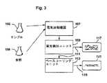
図3は、機器システムの実施形態の構成要素を図示し、この機器システムは、本明細書中の教示に従って分析されるべきデータシグナルを発生させるための、電気泳動および蛍光の検出機器を備える。別の構成要素間の適切なインターフェース(例えば、これらの構成要素をユニット間の情報の伝達に適合させるためのもの)が、それぞれ構成要素に備えられる。(Equipment system)
FIG. 3 illustrates the components of an embodiment of an instrument system, which instrument system comprises an electrophoresis and fluorescence detection instrument for generating a data signal to be analyzed according to the teachings herein. Appropriate interfaces between other components (eg, for adapting these components to the transmission of information between units) are provided in each component.
図3によれば、サンプル103および参照105のポリヌクレオチド溶液(おそらく、電気泳動および蛍光の検出のために調製されている)が、検出可能な成分への分離のために、電気泳動機器107に添加される。分離の間または分離後に、これらの成分は、励起ビーム(例えば、レーザー光)によって励起される場合に放出される蛍光によって、検出される。 According to FIG. 3, the polynucleotide solution of
蛍光検出ユニット109は、サンプルおよび参照配列のそれぞれのヌクレオチド塩基について、それぞれの蛍光の強度レベルを提示するシグナル111を発生させる。強度シグナル111が、ベースコーリングユニット113に出力され、そしてまた、記憶デバイス117(例えば、ディスプレイデバイス(モニタ)、プリンターまたはディスクドライブ)に送られ得る。 The
ベースコーリングユニット113は、本明細書中の教示を使用して、強度シグナル111を解釈し、そしてヌクレオチド塩基の配列に対応する出力121を提供する。ベースコーリングユニット113は、配列における、十分に高い信頼度で決定されない1つ以上の位置を特異的に標識し得ることが、理解されるべきである。
(コンピュータ実行)
図4は、特定の実施形態によるコンピュータシステム500を図示するブロック図であり、このコンピュータシステムにおいて、本教示の実施形態が実行され得る。コンピュータシステム500は、バス502または情報を通信するための他の通信機構、および情報を処理するためのバス502に結合されるプロセッサ504を備える。コンピュータシステム500はまた、メモリ506を備え、このメモリは、ランダムアクセスメモリ(RAM)または他の動的記憶デバイスであり得、ベースコール、およびプロセッサ504によって実行されるべき命令を決定するために、バス502に結合される。メモリ506はまた、プロセッサ504によって実行されるべき命令の実行の間に、一時的な変数または他の中間的な情報を記憶するために使用され得る。コンピュータシステム500は、静的情報およびプロセッサ504のための指示を記憶するための、バス502に結合されたリードオンリーメモリ(ROM)508または他の静的記憶デバイスをさらに備える。記憶デバイス510(例えば、磁気ディスクまたは光ディスク)が、情報および命令を記憶するために提供され、そしてバス502に結合される。(Computer execution)
FIG. 4 is a block diagram that illustrates a
コンピュータシステム500は、バス502を介して、コンピュータのユーザに情報を表示するためのディスプレイ512(例えば、陰極線管(CRT)または液晶ディスプレイ(LCD))に結合され得る。入力デバイス514(英数字および他のキーを備える)が、情報およびコマンド選択をプロセッサ504に通信するために、バス502に結合される。別の型のユーザ入力デバイスは、方向の情報およびコマンド選択をプロセッサ504に通信するため、ならびにカーソルの移動をディスプレイ512上で制御するための、カーソルコントロール516(例えば、マウス、トラックボールまたはカーソル方向キー)である。この入力デバイスは、代表的に、2つの軸(第1の軸(例えば、x)および第2の軸(例えば、y))での2の自由度を有し、これは、このデバイスが平面内で位置を特定することを可能にする。
ベースコールは、メモリ506に含まれる1つ以上の指示の1つ以上の順序を実行するプロセッサ504に応答して、コンピュータシステム500によって提供される。このような命令は、別のコンピュータ読み取り可能媒体(例えば、記憶デバイス510)から、メモリ506に読み込まれ得る。メモリ506に含まれる命令の順序の実行は、プロセッサ504に、本明細書中に記載されるプロセス状態を実施させる。あるいは、ハードワイヤード回路が、ソフトウェア指示の代わりにかまたはソフトウェア指示と組み合わせて使用されて、本教示を実行し得る。従って、本開示の実行は、ハードウェア回路とソフトウェアとのいずれの特定の組み合わせにも限定されない。 Base calls are provided by
用語「コンピュータ読み取り可能媒体」とは、本明細書中において使用される場合、実行のためにプロセッサ504に指示を提供することに関与する、任意の媒体をいう。このような媒体は、任意の形態をとり得、不揮発性媒体、揮発性媒体、および伝送媒体が挙げられるが、これらに限定されない。不揮発性媒体としては、例えば、光ディスクまたは磁気ディスク(例えば、記憶デバイス510)が挙げられる。揮発性媒体としては、動的メモリ(例えば、メモリ506)が挙げられる。伝送媒体としては、同軸ケーブル、銅線、および光ファイバーが挙げられ、バス502を構成するワイヤを含む。伝送媒体はまた、音波または光波の形態(例えば、伝播および赤外線のデータ通信の間に発生するもの)をとり得る。 The term “computer-readable medium” as used herein refers to any medium that participates in providing instructions to
コンピュータ読み取り可能媒体の通常の形態としては、例えば、フロッピー(登録商標)ディスク、フレキシブルディスク、ハードディスク、磁気テープ、または他の任意の磁気媒体、CD−ROM、他の任意の光媒体、穿孔カード、紙テープ、孔のパターンを有する他の任意の物理的媒体、RAM、PROM、およびEPROM、FLASH−EPROM、他の任意のメモリチップ、またはカートリッジ、本明細書中以下に記載されるような搬送波、あるいはコンピュータが読み取り得る他の任意の媒体が挙げられる。 Common forms of computer readable media include, for example, floppy disk, flexible disk, hard disk, magnetic tape, or any other magnetic medium, CD-ROM, any other optical medium, perforated card, Paper tape, any other physical medium with a pattern of holes, RAM, PROM, and EPROM, FLASH-EPROM, any other memory chip or cartridge, carrier wave as described herein below, or Any other medium that can be read by a computer can be mentioned.
種々の形態のコンピュータ読み取り可能媒体が、実行のためにプロセッサ504に1つ以上の指示の1つ以上の順序を運ぶことに関与し得る。例えば、これらの指示は、最初、遠隔コンピュータの磁気ディスク上で運ばれ得る。遠隔コンピュータは、これらの指示をその動的メモリにロードし得、そしてこれらの指示を、モデムを使用して電話回線を通して送信し得る。コンピュータシステム500に局在するモデムは、電話回線上のデータを受信し得、そして赤外線送信機を使用して、これらのデータを赤外線シグナルに変換し得る。バス502に結合された赤外線検出器は、赤外線シグナル中で運ばれるデータを受信し得、そしてバス502上にデータを配置し得る。バス502は、このデータをメモリ506に運び、このメモリ506から、プロセッサ504が指示を検索および実行する。メモリ506によって受信される指示は、必要に応じて、プロセッサ504による実行の前または後のいずれかに、記憶デバイス510に記憶され得る。 Various forms of computer readable media may be involved in carrying one or more orders of one or more instructions to
以下の実施例は、単なる例示であり、そして本発明の範囲および本発明に関する特許請求の範囲の範囲を、いずれの様式でも限定することは意図されない。 The following examples are merely illustrative and are not intended to limit the scope of the invention and the claims related to the invention in any way.
(実施例1)
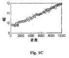
図1は、シミュレートされた5番目の色素の泳動からのデータを示す、電気泳動図である。x軸は、走査数であり、そしてy軸は、任意の単位での蛍光振幅である。各走査は、持続時間が約1秒間である。ピークの大部分は、等間隔である。すなわち、これらのピークは、各々18塩基で生じる。3700 POP5データ(Applied Biosystems;Foster City,CA)に類似の移動度を使用して、現実的な走査間隔をシミュレートした。これらのピークのうちの少数が、規則的な18塩基の間隔からずれている。このようなパターン化されたピークを使用して、開始位置(すなわち、塩基1)の絶対的な較正を提供する。同定を容易にするために、規則的に間隔を空けたピークは、空白(赤色)の円によって同定され、一方でパターン化されたピークは、塗りつぶされた(緑色の)円で同定される。Example 1
FIG. 1 is an electropherogram showing data from a simulated fifth dye run. The x-axis is the number of scans and the y-axis is the fluorescence amplitude in arbitrary units. Each scan has a duration of about 1 second. Most of the peaks are equally spaced. That is, these peaks occur at 18 bases each. Similar scans were used to simulate realistic scan intervals using 3700 POP5 data (Applied Biosystems; Foster City, CA). A few of these peaks deviate from regular 18 base intervals. Such a patterned peak is used to provide an absolute calibration of the starting position (ie base 1). To facilitate identification, regularly spaced peaks are identified by blank (red) circles, while patterned peaks are identified by filled (green) circles.
5番目の色素ラダー(図1A)から、図1Bおよび1Cの曲線が推定され得る。図1Bは、走査数の関数として、ピーク間の間隔を表す。この間隔はまた、走査数で報告される。図1Cの曲線は、各ピークの幅を、走査数で、走査数の関数として表す。この幅は、そのピークの最大高さの半分の全幅(FWHM)として測定され得る。 From the fifth dye ladder (FIG. 1A), the curves of FIGS. 1B and 1C can be deduced. FIG. 1B represents the spacing between peaks as a function of the number of scans. This interval is also reported in the number of scans. The curve in FIG. 1C represents the width of each peak in number of scans as a function of the number of scans. This width can be measured as the full width (FWHM) half the maximum height of the peak.
幅曲線(図1C)を使用して、デコンボリューション技術を改善し得る。いくつかの技術(例えば、WienerおよびMaximumのエントロピー)は、ピーク幅が比較的一定であるウィンドウに対して、フーリエ変換を実行する。走査軸を再補間して一定の幅を達成することによって、フーリエウィンドウは、データセット全体であり得る。このことは、有意に改善された実行時間をもたらし、そしてデコンボルブされたウィンドウを一緒に切り替える必要性を排除する。 The width curve (FIG. 1C) can be used to improve the deconvolution technique. Some techniques (eg, Wiener and Maximum entropy) perform Fourier transforms on windows where the peak width is relatively constant. By reinterpolating the scan axis to achieve a constant width, the Fourier window can be the entire data set. This results in significantly improved execution time and eliminates the need to switch deconvoluted windows together.
(実施例2)
図2は、本発明の実施形態によって企図される工程を示すフローチャートを提供する。(Example 2)
FIG. 2 provides a flowchart illustrating the steps contemplated by an embodiment of the present invention.
ピーク検出は、当該分野において公知の多数の技術によって、達成され得る。例えば、ピーク検出は、不連続にサンプリングされたEPデータにおける局所的極大の同定によって達成され得る。本発明の実施形態は、Savitsky−Golay平滑化を包含するアルゴリズムを利用する。ピーク特徴を評価するための任意の種々の技術が、本発明を実施する際に使用され得る。目的の特徴としては、以下が挙げられる:位置(走査)および形状(例えば、高さ、幅)。Savitsky−Golay平滑化はまた、これらの終了の近くに使用され得る。 Peak detection can be accomplished by a number of techniques known in the art. For example, peak detection can be achieved by identification of local maxima in discontinuously sampled EP data. Embodiments of the present invention utilize algorithms that include Savitsky-Golay smoothing. Any of a variety of techniques for evaluating peak features can be used in practicing the present invention. Features of interest include the following: position (scanning) and shape (eg height, width). Savitsky-Golay smoothing can also be used near these ends.
ピークの弁別がまた、種々の様式で達成され得る。種々の実施形態において、何らかの参照点からのピークの高さ−幅空間におけるユークリッド距離が記憶され、そして区別されて、引き続く分析のために考慮されるべきピークから、無視されるべきピークを分離する境界を決定する。 Peak discrimination can also be achieved in various ways. In various embodiments, the Euclidean distance in peak height-width space from some reference point is stored and distinguished to separate the peaks to be ignored from the peaks to be considered for subsequent analysis. Determine the boundary.
ピークをサイズ鮮明度からのサイズと適合させることは、RatioMatcher(このような作業のために設計された動的プログラミングアルゴリズム、米国仮特許出願番号60/129,697を参照のこと;本明細書中に参考として援用される)によって取り扱われ得る。本発明は、しばしば、比較的多数の大きさおよびピークを取り扱うことを包含するので、RatioMatcherは、いくつかの状況において、所望されるよりコンピュータ的に強くあり得る。しかし、RatioMatcherは、データのサブセットに対して使用され得、次いで、その結果が、より単純なアルゴリズム(5番目の色素データの特定の特徴(例えば、十分に改造された、ほぼ等しく間隔を空けたピーク)を利用する)のための開始点として使用され得る。 To match the peak to the size from size definition, see RatioMatcher (dynamic programming algorithm designed for such work, US Provisional Patent Application No. 60 / 129,697; herein Incorporated by reference). Since the present invention often involves handling a relatively large number of sizes and peaks, RatioMatcher can be more computationally stronger than desired in some situations. However, RatioMatcher can be used on a subset of the data, and then the result is a simpler algorithm (specific features of the fifth dye data (eg, well-modified, approximately equally spaced) Can be used as a starting point for).
5番目の色素データの分析の結果は、最初の4つの色素シグナルの処理および分析、ならびにピークの分類(すなわち、ベースのコーリング)を補助する。利点としては、以下が挙げられる:
5番目の色素のデータの十分に解像されたピークは、ピークの形状(幅、および充填/注入の異常、分離マトリックス中の気泡などに起因する不均一性の影響)ならびに間隔の良好な推定を、シグナルの位置の関数として提供する。これらの幅および間隔の推定は、乏しい解像度を有する付随するシグナルの、より良好な分析を可能にする。The results of the fifth dye data analysis assist in the processing and analysis of the first four dye signals, as well as peak classification (ie, base calling). Benefits include the following:
A well-resolved peak in the fifth dye data is a good estimate of peak shape (width and effects of non-uniformity due to filling / injection anomalies, bubbles in the separation matrix, etc.) and spacing As a function of signal position. These width and spacing estimates allow better analysis of the accompanying signal with poor resolution.
移動度シフトの較正は、参照点(通常、「塩基1」と称される)の位置に依存する。この参照点の推定は、5番目の色素のシグナル分析によって提供される、大きさ−走査マップによって改善される。 The mobility shift calibration depends on the position of the reference point (usually referred to as “
(実施例3)
本開示の1つの例によれば、ラダーは、5番目の色素で標識されたフラグメントを、10〜20塩基ごとに、塩基約20〜塩基約1200〜1500(すなわち、少なくとも60フラグメント)で含むように、設計および構築される。さらなる2〜3個のピークは、塩基1の推定の開始の近くに存在するように設計され得る。ラダー配列は、この実施形態において、標準的な条件下で泳動される場合に、ほぼ「通常の」移動(例えば、4つ全ての塩基の全く等しい提示を有することによる)を示し、そして実質的な移動度不規則性を示さない。このラダーは、例えば、反復内部ユニットからなり得、従って、ピーク間で、同じ配列の一定の数の塩基が存在する。このラダーは、例えば、一塩基配列決定反応から生じ得る。別の実施形態において、テンプレートは、さらなるピークを含むが、(少なくとも約5塩基)単離されたピークを約20塩基程度ごとに含む。理想的には、これは、上記反復ユニットを含む。(Example 3)
According to one example of the present disclosure, the ladder includes fragments labeled with the fifth dye every 10-20 bases, from about 20 bases to about 1200-1500 bases (ie, at least 60 fragments). To be designed and built. An additional few peaks can be designed to exist near the start of
(実施例4)
この実施例は、以下の2つの異なる型の生成物を企図する:(a)合成(および連結)された核酸配列のセット、ならびに(b)合成およびクローニングされた核酸配列のセット。生成物(a)は、種々の大きさの、(5’末端が標識された)5番目の色素で標識されたフラグメントから構成され、これは、泳動される場合に、例えば、3700または3100DNA Analyzer(Applied Biosystems;Foster City,CA)で泳動される場合に、5番目の色素のラダーを生じる。生成物(b)は、5番目の色素で標識されたジでオキシターミネーターを用いて、例えば、−21M13万能プライマーを使用して配列決定される場合、(3’末端が標識された)5番目の色素のラダーを生じるために使用され得るクローンである。Example 4
This example contemplates two different types of products: (a) a set of synthesized (and ligated) nucleic acid sequences, and (b) a set of synthesized and cloned nucleic acid sequences. The product (a) is composed of fragments of various sizes and labeled with a fifth dye (labeled at the 5 'end), which when run, for example 3700 or 3100 DNA Analyzer When run on (Applied Biosystems; Foster City, CA), a fifth dye ladder is generated. Product (b) is the fifth (labeled at the 3 'end) when sequenced using a di-oxyterminator labeled with a fifth dye, for example using the -21M13 universal primer. A clone that can be used to produce a dye ladder.
5番目の色素のラダーは、配列決定サンプルと共に、例えば、ABI DNA 分析機器で泳動され得る。このラダーは、大きさが、例えば、18または19〜7200を超える塩基までの範囲であり得、1つの5番目の色素で標識されたフラグメントは、10〜50塩基ごと(例えば、12または18塩基ごとなど)である。 The fifth dye ladder can be run with the sequencing sample, eg, on an ABI DNA analyzer. This ladder can range in size, for example, from 18 or more than 19 to 7200 bases, and a fragment labeled with one fifth dye is every 10-50 bases (eg, 12 or 18 bases). Etc.).
生成物(a)または(b)の実施形態において、5番目の色素で標識された3つのさらなるフラグメントが、5番目の色素ターミネーター配列決定反応によって、塩基57、87、および94の近くに生じた。 In product (a) or (b) embodiments, three additional fragments labeled with the fifth dye were generated near bases 57, 87, and 94 by the fifth dye terminator sequencing reaction. .
(実施例5)
最初の較正標準は、3つの塩基(例えば、G、C、A、Tのいずれか3つ)がその配列の長さに沿ってランダムに組み込まれ、そして4番目の塩基(例えば、G、C、A、Tの4番目)が、その配列の長さに沿って規則的に間隔を空けた(例えば、10番目の塩基位置ごと)間隔で(そしてこの間隔でのみ)組み込まれた配列を含んで作製される。第4の塩基は、標準的な配列決定反応を使用して、独特の蛍光標識で標識される。(Example 5)
The first calibration standard is that three bases (eg, any three of G, C, A, T) are randomly incorporated along the length of the sequence, and the fourth base (eg, G, C , A, T of 4) includes sequences incorporated at intervals (and only at this interval) regularly spaced along the length of the sequence (eg, every 10th base position). It is made with. The fourth base is labeled with a unique fluorescent label using standard sequencing reactions.
(実施例6)
この実施例は、実施例4の生成物(b)に関して上記したものと類似の様式で構築された、5番目の色素ラダーに関する。(Example 6)
This example relates to a fifth dye ladder constructed in a manner similar to that described above for the product (b) of Example 4.
最初のクローニングインサート(小容量)を、1つのGのみ(これは、12マーの末端に存在する)を含む12マーの自己連結によって作製した。より大きい量を、連結産物をクローニングすることによって、生成した。次いで、規則的な4つの色素配列決定反応を、クローン産物に対して実施した。図5は、配列決定データからのこのGのみの追跡を示すプロットである。示されるように、このプロットにおける軸は、より適切かつ有用な部分にズームインするようにクリッピングされて示される。 The initial cloning insert (small volume) was made by 12-mer self-ligation containing only one G (which is at the end of the 12-mer). Larger amounts were generated by cloning the ligation product. A regular four dye sequencing reaction was then performed on the cloned product. FIG. 5 is a plot showing this G-only tracking from sequencing data. As shown, the axes in this plot are shown clipped to zoom in on a more relevant and useful part.
(実施例7)
この実施例は、サンプルの注入/充填のモニタリングに関する。(Example 7)
This example relates to sample injection / filling monitoring.
96個の配列決定サンプルを、各々、5番目の色素フラグメントのセットと混合した。次いで、これらのサンプルを、ABI Prism 3700 DNA Analyzer機器に充填し、そして泳動(分離)し、そしてシグナルを収集した。図6は、3700機器からこれらのサンプルの各々に対して報告されたシグナルを示す。サンプルの完全性は、各サンプルの結果を個々に調査することによって、決定され得る。この図において、C01位置におけるサンプルは、いずれの配列決定シグナル(色素1〜4)をも示さず5番目の色素シグナルが存在した。このことは、C01には配列決定反応生成物が存在しないことを示し、このことは、プロセスの反応段階における問題を示す。他方で、プロフィールA03は、配列決定と5番目の色素シグナルとの両方において、シグナルを示さなかった。このことは、サンプル充填(注入)の問題が起こったかもしれないことを示す。E05位置は、配列決定と5番目の色素のシグナルとの両方を示したが、それぞれが、他の実験におけるそれらのプロフィールに相対的であるようであることを示した。このことは、キャピラリーまたは充填ウェル、あるいはサンプルの純度さえにおける問題を示し得る。 Each of the 96 sequencing samples was mixed with the fifth set of dye fragments. These samples were then loaded into an ABI Prism 3700 DNA Analyzer instrument and run (separated) and the signal collected. FIG. 6 shows the signal reported for each of these samples from a 3700 instrument. Sample integrity can be determined by examining the results of each sample individually. In this figure, the sample at the C01 position did not show any sequencing signal (dyes 1-4) and there was a fifth dye signal. This indicates that there is no sequencing reaction product in C01, which indicates a problem in the reaction stage of the process. On the other hand, profile A03 showed no signal in both sequencing and the fifth dye signal. This indicates that a sample filling (injection) problem may have occurred. The E05 position showed both sequencing and 5th dye signal, but each seemed to be relative to their profile in other experiments. This can indicate a problem in the capillary or packed well, or even the purity of the sample.
本明細書中で言及された全ての刊行物および特許出願は、各個々の刊行物または特許出願が具体的にかつ個別に、参考として援用されると示されたと同じ程度まで、本明細書中に参考として援用される。 All publications and patent applications mentioned in this specification are herein to the same extent as each individual publication or patent application was specifically and individually indicated to be incorporated by reference. Is incorporated by reference.
当業者は、多くの改変が可能であることを理解する。このような改変の全ては、本明細書中に包含されることが意図される。 Those skilled in the art will appreciate that many modifications are possible. All such modifications are intended to be included herein.
本発明の教示の例示的な構造および操作様式は、それらの種々の目的および利点とともに、添付の図面と組み合わせて与えられる以下の説明に記載される。ここで、同一の参照番号は、類似または同様な要素を同定する。
Claims (5)
Translated fromJapanese(i)該装置の細長分離チャネル中に、(a)未知のヌクレオチド配列の複数の分析物のポリヌクレオチドフラグメントを含むサンプルであって、該フラグメントの各々は、第1、第2、第3または第4の蛍光標識と結合する、サンプル、および(b)既知のヌクレオチド長の複数のポリヌクレオチドフラグメントを含む内部標準であって、該ポリヌクレオチドフラグメントの各々が、第5の蛍光標識と結合する、内部標準、を提供する工程であって;ここで該第1、第2、第3および第4の蛍光標識は、該サンプル中に存在し、そしてさらにここで、該第1、第2、第3、第4および第5の蛍光標識は、互いにスペクトル識別可能である、工程;
(ii)該ポリヌクレオチドフラグメントを電気泳動分離する工程;
(iii)(a)分離しているまたは分離されたポリヌクレオチドフラグメントの標識が該装置の検出ゾーンに沿って通過する場合、該分離しているかまたは分離されたポリヌクレオチドフラグメントの標識から蛍光発光を誘発する工程、(b)該誘発された蛍光発光を検出する工程、および(c)該検出された標識の各々についての蛍光強度トレースを表すデータを収集する、工程;
(iv)該第5の標識に対応するトレースのピークを位置決めし、該ピークの形状を決定する、工程;ならびに
(v)該ピークの形状に少なくとも部分的に基づいて較正モデルを作成し、該モデルを、該第1、第2、第3および第4の標識に対応するピークの位置決めおよび分析に適用する、工程、
を包含する、方法。A method for calibrating an apparatus for analysis of polynucleotides comprising:
(I) a sample comprising in the elongated separation channel of the device (a) a plurality of analyte polynucleotide fragments of unknown nucleotide sequence, each of the fragments comprising a first, second, third or A sample that binds to a fourth fluorescent label, and (b) an internal standard comprising a plurality of polynucleotide fragments of known nucleotide length, each of the polynucleotide fragments binding to a fifth fluorescent label; Providing the internal standard; wherein the first, second, third and fourth fluorescent labels are present in the sample, and further wherein the first, second, second The third, fourth and fifth fluorescent labels are spectrally distinguishable from each other;
(Ii) electrophoretically separating the polynucleotide fragment;
(Iii) (a) If the label of the separated or separated polynucleotide fragment passes along the detection zone of the device, fluorescence is emitted from the label of the separated or separated polynucleotide fragment. Inducing, (b) detecting the induced fluorescence emission, and (c) collecting data representing a fluorescence intensity trace for each of the detected labels;
(Iv) locating the peak of the trace corresponding to the fifth label and determining the shape of the peak; and (v) creating a calibration model based at least in part onthe shape of thepeak ; Applying a model to the positioning and analysis of peaks corresponding to the first, second, third and fourth labels;
Including the method.
(vi)該分析物のポリヌクレオチドフラグメントについてのベースコールを作製する工程、
をさらに包含する、方法。2. The method of claim 1, wherein the nucleotide sequence of the polynucleotide fragment of the analyte is determined, the method comprising the following steps:
(Vi) creating a base call for the polynucleotide fragment of the analyte;
Further comprising a method.
(i)1つ以上の配列決定サンプルを内部標準と組み合わせて、1つ以上のそれぞれのサンプル混合物を形成する工程であって;該配列決定サンプルの各々は、未知のヌクレオチド配列の複数の分析物ポリヌクレオチドフラグメントを含み、該分析物ポリヌクレオチドフラグメントは、第1、第2、第3または第4の蛍光標識と結合し;ここで該内部標準は、既知のヌクレオチド長の1つ以上のポリヌクレオチドフラグメントを含み、該1つ以上のポリヌクレオチドフラグメントの各々は、第5の蛍光標識と結合し;さらにここで、該第1、第2、第3、第4および第5の蛍光標識は、互いにスペクトル識別可能である、工程;
(ii)該サンプル混合物を、該装置のそれぞれの分離レーンに充填する工程;
(iii)該サンプル混合物の各々を、そのそれぞれのレーンを下向きに、その検出ゾーンに沿って移動させるのに十分な電気泳動力を適用する工程;
(iv)分離しているポリヌクレオチドフラグメントまたは分離されたポリヌクレオチドフラグメントが該検出ゾーンを通過する場合に、該分離しているポリヌクレオチドフラグメントまたは分離されたポリヌクレオチドフラグメントの標識から蛍光発光を誘発するのに十分な励起放射線を、該検出ゾーンに向かって方向付ける工程、(b)誘発された蛍光発光について検出する工程、および(c)該検出された標識の各々の蛍光強度トレースを示すデータを収集する工程;
(v)各サンプル混合物について、該第5の標識のトレースのピークを決定し、そしてピークの位置およびピークの半値幅を決定する工程;
(vi)工程(v)の該検出されたピークについてのピークからピークの距離を決定する工程;ならびに
(vii)工程(v)および(vi)からの結果を使用して、分解能値を算出する工程、
を包含する方法。A method for determining the resolution of a polynucleotide analyte using an electrophoresis apparatus, comprising:
(I) combining one or more sequencing samples with an internal standard to form one or more respective sample mixtures; each sequencing sample comprising a plurality of analytes of unknown nucleotide sequence; A polynucleotide fragment, wherein the analyte polynucleotide fragment binds to a first, second, third or fourth fluorescent label; wherein the internal standard is one or more polynucleotides of known nucleotide length Each of the one or more polynucleotide fragments is associated with a fifth fluorescent label; and further wherein the first, second, third, fourth and fifth fluorescent labels are attached to each other Spectrally distinguishable, process;
(Ii) filling the sample mixture into each separation lane of the device;
(Iii) applying an electrophoretic force sufficient to move each of the sample mixtures down its respective lane along its detection zone;
(Iv) When a separated polynucleotide fragment or separated polynucleotide fragment passes through the detection zone, fluorescence emission is induced from the label of the separated polynucleotide fragment or separated polynucleotide fragment. Directing excitation radiation sufficient to the detection zone; (b) detecting for induced fluorescence emission; and (c) data indicating a fluorescence intensity trace of each of the detected labels. Collecting steps;
(V) determining, for each sample mixture, the peak of the fifth label trace and determining the peak position and half-width of the peak;
(Vi) determining a peak-to-peak distance for the detected peak of step (v); and (vii) using the results from steps (v) and (vi) to calculate a resolution value. Process,
Including the method.
蛍光強度シグナルのセットを受信する工程であって、該セットの該蛍光強度シグナルの各々は、複数の成分シグナルから構成され、該成分シグナルの各々は、未知のヌクレオチド配列の複数の分析物ポリヌクレオチドフラグメントを含む多成分混合物中のそれぞれのヌクレオチド塩基または内部標準を示す、工程;
該内部標準に対応する第1の成分シグナルを決定する工程;
該それぞれのヌクレオチド塩基を示す、第2、第3、第4および第5の成分シグナルを決定する工程;
該第1成分シグナルからの特徴を同定し、そのピークの形状を決定する工程;ならびに
該ピークの形状に少なくとも部分的に基づいて較正モデルを作成し、該較正モデルを、該第2、第3、第4および第5の成分シグナルに適用する工程、を包含する、
デバイス。A machine readable program storage device that embodies an instruction program executable by the machine and performs method steps for calibration of polynucleotide sequence data, the method steps comprising: Process:
Receiving a set of fluorescence intensity signals, each of the fluorescence intensity signals of the set comprising a plurality of component signals, each of the component signals comprising a plurality of analyte polynucleotides of unknown nucleotide sequence Showing each nucleotide base or internal standard in a multi-component mixture containing fragments;
Determining a first component signal corresponding to the internal standard;
Determining second, third, fourth and fifth component signals indicative of said respective nucleotide bases;
And identifying features from the first component signal, a step of determining the shape ofthe peak; Create a calibration model based at least in part onthe shape of and thepeak, the said calibration model, the second, Applying to the third, fourth and fifth component signals,
device.
Applications Claiming Priority (2)
| Application Number | Priority Date | Filing Date | Title |
|---|---|---|---|
| US30493401P | 2001-07-11 | 2001-07-11 | |
| PCT/US2002/022147WO2003006692A1 (en) | 2001-07-11 | 2002-07-11 | Internal calibration standards for electrophoretic analyses |
Related Child Applications (1)
| Application Number | Title | Priority Date | Filing Date |
|---|---|---|---|
| JP2007215327ADivisionJP2008005850A (en) | 2001-07-11 | 2007-08-21 | Internal calibration standard for electrophoretic analyze |
Publications (3)
| Publication Number | Publication Date |
|---|---|
| JP2004535198A JP2004535198A (en) | 2004-11-25 |
| JP2004535198A5 JP2004535198A5 (en) | 2005-12-22 |
| JP4436672B2true JP4436672B2 (en) | 2010-03-24 |
Family
ID=23178590
Family Applications (2)
| Application Number | Title | Priority Date | Filing Date |
|---|---|---|---|
| JP2003512449AExpired - Fee RelatedJP4436672B2 (en) | 2001-07-11 | 2002-07-11 | Internal calibration standard for electrophoretic analysis |
| JP2007215327AWithdrawnJP2008005850A (en) | 2001-07-11 | 2007-08-21 | Internal calibration standard for electrophoretic analyze |
Family Applications After (1)
| Application Number | Title | Priority Date | Filing Date |
|---|---|---|---|
| JP2007215327AWithdrawnJP2008005850A (en) | 2001-07-11 | 2007-08-21 | Internal calibration standard for electrophoretic analyze |
Country Status (5)
| Country | Link |
|---|---|
| US (2) | US7593819B2 (en) |
| EP (2) | EP2184369A1 (en) |
| JP (2) | JP4436672B2 (en) |
| CA (1) | CA2453360A1 (en) |
| WO (1) | WO2003006692A1 (en) |
Cited By (1)
| Publication number | Priority date | Publication date | Assignee | Title |
|---|---|---|---|---|
| DE112018007805B4 (en)* | 2018-08-02 | 2024-10-24 | Hitachi High-Tech Corporation | biopolymer analysis method and biopolymer analysis device |
Families Citing this family (26)
| Publication number | Priority date | Publication date | Assignee | Title |
|---|---|---|---|---|
| JP4436672B2 (en)* | 2001-07-11 | 2010-03-24 | アプライド バイオシステムズ, エルエルシー | Internal calibration standard for electrophoretic analysis |
| GB0419482D0 (en)* | 2004-09-02 | 2004-10-06 | Sec Dep For The Home Departmen | Improvements in and relating to analysis |
| US7647188B2 (en)* | 2004-09-15 | 2010-01-12 | F. Hoffmann-La Roche Ag | Systems and methods for processing nucleic acid chromatograms |
| JP4742712B2 (en)* | 2005-07-14 | 2011-08-10 | 株式会社島津製作所 | Capillary electrophoresis method |
| KR101163425B1 (en) | 2006-04-14 | 2012-07-13 | 닛본 덴끼 가부시끼가이샤 | Individual discrimination method and apparatus |
| JP5218423B2 (en)* | 2006-12-28 | 2013-06-26 | 和光純薬工業株式会社 | Method for normalizing assay systems |
| US8871524B2 (en)* | 2009-08-12 | 2014-10-28 | Caliper Life Sciences, Inc. | Methods of performing a sizing analysis using a corrected sizing ladder |
| WO2013067489A1 (en) | 2011-11-05 | 2013-05-10 | President And Fellows Of Harvard College | Nucleic acid-based linkers for detecting and measuring interactions |
| US9005419B2 (en) | 2012-05-29 | 2015-04-14 | Health Diagnostic Laboratory, Inc. | Composition and method for gel electrophoresis with in-situ calibration |
| WO2016025892A1 (en) | 2014-08-15 | 2016-02-18 | Life Technologies Corporation | Methods and systems for detecting minor variants in a sample of genetic material |
| GB201418144D0 (en)* | 2014-10-14 | 2014-11-26 | Univ Cardiff | High throughput sequencing |
| WO2016089588A1 (en) | 2014-12-06 | 2016-06-09 | Children's Medical Center Corporation | Nucleic acid-based linkers for detecting and measuring interactions |
| US9809849B2 (en)* | 2015-02-06 | 2017-11-07 | Life Technologies Corporation | Methods and systems for pure dye instrument normalization |
| KR102541746B1 (en)* | 2015-02-06 | 2023-06-09 | 라이프 테크놀로지스 코포레이션 | Methods and systems for experimental design and analysis |
| CN107889521B (en)* | 2015-02-06 | 2020-03-27 | 生命技术公司 | Method and system for determining an optical region of interest |
| WO2016196824A1 (en) | 2015-06-02 | 2016-12-08 | Children's Medical Center Corporation | Nucleic acid complexes for screening barcoded compounds |
| US12077807B2 (en) | 2015-06-27 | 2024-09-03 | The Research Foundation For The State University Of New York | Compositions and methods for analyte detection using nanoswitches |
| GB201511508D0 (en)* | 2015-07-01 | 2015-08-12 | Ge Healthcare Bio Sciences Ab | Method for determining a size of biomolecules |
| JP7003035B2 (en)* | 2015-11-03 | 2022-02-10 | アスラジェン, インコーポレイテッド | Methods for detecting nucleic acid size of repeat sequences |
| WO2017139409A1 (en) | 2016-02-09 | 2017-08-17 | Children's Medical Center Corporation | Method for detection of analytes via polymer complexes |
| WO2017165647A1 (en)* | 2016-03-23 | 2017-09-28 | Children's Medical Center Corporation | Rapid and sensitive detection and quantification of analytes in complex samples using polymer-based methods |
| WO2017165585A1 (en) | 2016-03-23 | 2017-09-28 | Children's Medical Center Corporation | Systems and apparatus for detecting compounds in human biological samples |
| MX2018013686A (en)* | 2016-10-24 | 2019-05-02 | Two Pore Guys Inc | Fractional abundance of polynucleotide sequences in a sample. |
| WO2019100080A1 (en) | 2017-11-20 | 2019-05-23 | Children's Medical Center Corporation | Force-controlled nanoswitch assays for single-molecule detection in complex biological fluids |
| JP2025007748A (en)* | 2023-07-03 | 2025-01-17 | 株式会社日立製作所 | Method for quantitative analysis of gene mutations, quantitative analysis device, and quantitative analysis kit |
| CN118737290B (en)* | 2024-06-13 | 2025-05-02 | 德诺杰亿(北京)生物科技有限公司 | Internal standard matching method, system and equipment for detection spectrum of gene analyzer |
Family Cites Families (31)
| Publication number | Priority date | Publication date | Assignee | Title |
|---|---|---|---|---|
| US611683A (en)* | 1898-10-04 | Mail-box | ||
| US2280728A (en)* | 1939-11-24 | 1942-04-21 | Rca Corp | Telescoping high frequency electrical conductor |
| US4660151A (en)* | 1983-09-19 | 1987-04-21 | Beckman Instruments, Inc. | Multicomponent quantitative analytical method and apparatus |
| US5633129A (en)* | 1989-07-13 | 1997-05-27 | Massachusetts Institute Of Technology | Electrophoretic detection and separation of mutant DNA using replaceable polymer matrices |
| US5119316A (en)* | 1990-06-29 | 1992-06-02 | E. I. Du Pont De Nemours And Company | Method for determining dna sequences |
| US5116316A (en)* | 1991-02-25 | 1992-05-26 | Baxter International Inc. | Automatic in-line reconstitution system |
| JP2974495B2 (en) | 1992-04-24 | 1999-11-10 | 株式会社日立製作所 | Electrophoresis apparatus and electrophoresis method |
| US5365455A (en)* | 1991-09-20 | 1994-11-15 | Vanderbilt University | Method and apparatus for automatic nucleic acid sequence determination |
| DE69231646T2 (en)* | 1991-10-23 | 2001-06-13 | Baylor College Of Medicine, Houston | FINGERPRINT-LIKE IDENTIFICATION OF BACTERIA STRAINS BY AMPLIFICATING REPETITIVE DNA SEQUENCES |
| US5843680A (en)* | 1992-01-31 | 1998-12-01 | Biometric Imaging, Inc. | Differential separation assay methods and test kits |
| US5580728A (en)* | 1994-06-17 | 1996-12-03 | Perlin; Mark W. | Method and system for genotyping |
| US5916747A (en)* | 1995-06-30 | 1999-06-29 | Visible Genetics Inc. | Method and apparatus for alignment of signals for use in DNA based-calling |
| US5748491A (en) | 1995-12-20 | 1998-05-05 | The Perkin-Elmer Corporation | Deconvolution method for the analysis of data resulting from analytical separation processes |
| US5795722A (en) | 1997-03-18 | 1998-08-18 | Visible Genetics Inc. | Method and kit for quantitation and nucleic acid sequencing of nucleic acid analytes in a sample |
| US5871628A (en)* | 1996-08-22 | 1999-02-16 | The University Of Texas System | Automatic sequencer/genotyper having extended spectral response |
| AU4588297A (en) | 1996-09-16 | 1998-04-02 | Andy F. Marks | Method and apparatus for analysis of chromatographic migration patterns |
| US6251591B1 (en)* | 1997-02-27 | 2001-06-26 | Lorne Park Research, Inc. | Quantitative method for detecting nucleotide concentration |
| US6195449B1 (en)* | 1997-05-18 | 2001-02-27 | Robert Bogden | Method and apparatus for analyzing data files derived from emission spectra from fluorophore tagged nucleotides |
| SE9702008D0 (en) | 1997-05-28 | 1997-05-28 | Pharmacia Biotech Ab | A method and a system for nucleic acid seouence analysis |
| US6131072A (en)* | 1998-02-03 | 2000-10-10 | Pe Applied Biosystems, A Division Of Perkin-Elmer | Lane tracking system and method |
| US6236944B1 (en) | 1998-04-16 | 2001-05-22 | Northeastern University | Expert system for analysis of DNA sequencing electropherograms |
| IL141329A (en) | 1998-08-19 | 2005-07-25 | Bioventures Inc | Method for detemining polynucleotides sequence variations |
| US6821402B1 (en)* | 1998-09-16 | 2004-11-23 | Applera Corporation | Spectral calibration of fluorescent polynucleotide separation apparatus |
| US6554985B2 (en) | 1998-11-10 | 2003-04-29 | Curagen Corporation | Methods and formulations for the separation of biological macromolecules |
| US6110683A (en) | 1999-01-08 | 2000-08-29 | Commonwealth Biotechnologies, Inc. | Automated DNA Sequencer loading dye which contains a lane tracking aid |
| US7655443B1 (en)* | 1999-05-07 | 2010-02-02 | Siemens Healthcare Diagnostics, Inc. | Nucleic acid sequencing with simultaneous quantitation |
| IL147915A0 (en) | 1999-08-05 | 2002-08-14 | Takeda Chemical Industries Ltd | Method of recording gene analysis data |
| EP1237760B1 (en)* | 1999-12-16 | 2004-09-08 | Siemens Aktiengesellschaft | Method and device for determining the absolute angle of rotation of an object that is rotating around an approximately horizontal rotational axis |
| US6397150B1 (en)* | 2000-07-27 | 2002-05-28 | Visible Genetics Inc. | Method and apparatus for sequencing of DNA using an internal calibrant |
| US6681186B1 (en)* | 2000-09-08 | 2004-01-20 | Paracel, Inc. | System and method for improving the accuracy of DNA sequencing and error probability estimation through application of a mathematical model to the analysis of electropherograms |
| JP4436672B2 (en)* | 2001-07-11 | 2010-03-24 | アプライド バイオシステムズ, エルエルシー | Internal calibration standard for electrophoretic analysis |
- 2002
- 2002-07-11JPJP2003512449Apatent/JP4436672B2/ennot_activeExpired - Fee Related
- 2002-07-11EPEP10000723Apatent/EP2184369A1/ennot_activeWithdrawn
- 2002-07-11USUS10/193,776patent/US7593819B2/ennot_activeExpired - Lifetime
- 2002-07-11CACA002453360Apatent/CA2453360A1/ennot_activeAbandoned
- 2002-07-11EPEP02753373Apatent/EP1404878A4/ennot_activeWithdrawn
- 2002-07-11WOPCT/US2002/022147patent/WO2003006692A1/enactiveIP Right Grant
- 2007
- 2007-08-21JPJP2007215327Apatent/JP2008005850A/ennot_activeWithdrawn
- 2009
- 2009-09-17USUS12/562,070patent/US8268558B2/ennot_activeExpired - Fee Related
Cited By (1)
| Publication number | Priority date | Publication date | Assignee | Title |
|---|---|---|---|---|
| DE112018007805B4 (en)* | 2018-08-02 | 2024-10-24 | Hitachi High-Tech Corporation | biopolymer analysis method and biopolymer analysis device |
Also Published As
| Publication number | Publication date |
|---|---|
| CA2453360A1 (en) | 2003-01-23 |
| JP2008005850A (en) | 2008-01-17 |
| JP2004535198A (en) | 2004-11-25 |
| US20100206730A1 (en) | 2010-08-19 |
| WO2003006692A1 (en) | 2003-01-23 |
| US8268558B2 (en) | 2012-09-18 |
| US7593819B2 (en) | 2009-09-22 |
| EP1404878A1 (en) | 2004-04-07 |
| EP1404878A4 (en) | 2006-12-06 |
| US20030032042A1 (en) | 2003-02-13 |
| EP2184369A1 (en) | 2010-05-12 |
Similar Documents
| Publication | Publication Date | Title |
|---|---|---|
| JP4436672B2 (en) | Internal calibration standard for electrophoretic analysis | |
| US6991712B2 (en) | Spectral calibration of fluorescent polynucleotide separation apparatus | |
| US12176072B2 (en) | Methods and systems for visualizing and evaluating data | |
| CA2321821A1 (en) | Method for sequencing nucleic acids with reduced errors | |
| US20190360037A1 (en) | Methods and systems for nucleic acid sequencing validation, calibration and normalization | |
| JP4360479B2 (en) | A method of using quality assessment criteria to assess the quality of biochemical separations. | |
| CN102395977A (en) | Methods for nucleic acid quantification | |
| AU2002313667B2 (en) | Internal calibration standards for electrophoretic analyses | |
| AU2007202396A1 (en) | Internal calibration standards for electrophoretic analyses | |
| AU2011253591A1 (en) | Internal calibration standards for electrophoretic analyses | |
| AU2002313667A1 (en) | Internal calibration standards for electrophoretic analyses | |
| US20140336949A1 (en) | Method, apparatus, and kit for analyzing genes | |
| AU763102B2 (en) | Spectral calibration of fluorescent polynucleotide separation apparatus | |
| JP2004177290A (en) | Processing method of gene analysis data | |
| JP2025007748A (en) | Method for quantitative analysis of gene mutations, quantitative analysis device, and quantitative analysis kit | |
| Kotková | Determination of length of nucleic acid fragments by digital capillary electrophoresis | |
| US6406854B1 (en) | Method and compositions for evaluating resolution of nucleic acid separation systems | |
| CN118010685A (en) | Method, device and medium for determining inter-channel crosstalk correction intensity | |
| CN117887815A (en) | Method for detecting integrity of short nucleic acid sequence by base resolution |
Legal Events
| Date | Code | Title | Description |
|---|---|---|---|
| A131 | Notification of reasons for refusal | Free format text:JAPANESE INTERMEDIATE CODE: A131 Effective date:20070227 | |
| A601 | Written request for extension of time | Free format text:JAPANESE INTERMEDIATE CODE: A601 Effective date:20070525 | |
| A602 | Written permission of extension of time | Free format text:JAPANESE INTERMEDIATE CODE: A602 Effective date:20070601 | |
| A601 | Written request for extension of time | Free format text:JAPANESE INTERMEDIATE CODE: A601 Effective date:20070626 | |
| A602 | Written permission of extension of time | Free format text:JAPANESE INTERMEDIATE CODE: A602 Effective date:20070703 | |
| A601 | Written request for extension of time | Free format text:JAPANESE INTERMEDIATE CODE: A601 Effective date:20070726 | |
| A602 | Written permission of extension of time | Free format text:JAPANESE INTERMEDIATE CODE: A602 Effective date:20070802 | |
| A521 | Request for written amendment filed | Free format text:JAPANESE INTERMEDIATE CODE: A523 Effective date:20070821 | |
| A131 | Notification of reasons for refusal | Free format text:JAPANESE INTERMEDIATE CODE: A131 Effective date:20080507 | |
| A601 | Written request for extension of time | Free format text:JAPANESE INTERMEDIATE CODE: A601 Effective date:20080901 | |
| A601 | Written request for extension of time | Free format text:JAPANESE INTERMEDIATE CODE: A601 Effective date:20080807 | |
| A602 | Written permission of extension of time | Free format text:JAPANESE INTERMEDIATE CODE: A602 Effective date:20080908 | |
| A602 | Written permission of extension of time | Free format text:JAPANESE INTERMEDIATE CODE: A602 Effective date:20080917 | |
| A601 | Written request for extension of time | Free format text:JAPANESE INTERMEDIATE CODE: A601 Effective date:20081006 | |
| A602 | Written permission of extension of time | Free format text:JAPANESE INTERMEDIATE CODE: A602 Effective date:20081014 | |
| A521 | Request for written amendment filed | Free format text:JAPANESE INTERMEDIATE CODE: A523 Effective date:20081105 | |
| A131 | Notification of reasons for refusal | Free format text:JAPANESE INTERMEDIATE CODE: A131 Effective date:20081224 | |
| A601 | Written request for extension of time | Free format text:JAPANESE INTERMEDIATE CODE: A601 Effective date:20090324 | |
| A602 | Written permission of extension of time | Free format text:JAPANESE INTERMEDIATE CODE: A602 Effective date:20090331 | |
| A601 | Written request for extension of time | Free format text:JAPANESE INTERMEDIATE CODE: A601 Effective date:20090423 | |
| A602 | Written permission of extension of time | Free format text:JAPANESE INTERMEDIATE CODE: A602 Effective date:20090501 | |
| A601 | Written request for extension of time | Free format text:JAPANESE INTERMEDIATE CODE: A601 Effective date:20090522 | |
| A602 | Written permission of extension of time | Free format text:JAPANESE INTERMEDIATE CODE: A602 Effective date:20090529 | |
| A711 | Notification of change in applicant | Free format text:JAPANESE INTERMEDIATE CODE: A712 Effective date:20090618 | |
| A521 | Request for written amendment filed | Free format text:JAPANESE INTERMEDIATE CODE: A523 Effective date:20090624 | |
| TRDD | Decision of grant or rejection written | ||
| A01 | Written decision to grant a patent or to grant a registration (utility model) | Free format text:JAPANESE INTERMEDIATE CODE: A01 Effective date:20091203 | |
| A01 | Written decision to grant a patent or to grant a registration (utility model) | Free format text:JAPANESE INTERMEDIATE CODE: A01 | |
| A61 | First payment of annual fees (during grant procedure) | Free format text:JAPANESE INTERMEDIATE CODE: A61 Effective date:20091228 | |
| R150 | Certificate of patent or registration of utility model | Free format text:JAPANESE INTERMEDIATE CODE: R150 | |
| FPAY | Renewal fee payment (event date is renewal date of database) | Free format text:PAYMENT UNTIL: 20130108 Year of fee payment:3 | |
| LAPS | Cancellation because of no payment of annual fees |