JP4436517B2 - Self-standing bag making and filling and packaging equipment - Google Patents
Self-standing bag making and filling and packaging equipmentDownload PDFInfo
- Publication number
- JP4436517B2 JP4436517B2JP2000022844AJP2000022844AJP4436517B2JP 4436517 B2JP4436517 B2JP 4436517B2JP 2000022844 AJP2000022844 AJP 2000022844AJP 2000022844 AJP2000022844 AJP 2000022844AJP 4436517 B2JP4436517 B2JP 4436517B2
- Authority
- JP
- Japan
- Prior art keywords
- packaging film
- seal
- self
- filling
- pair
- Prior art date
- Legal status (The legal status is an assumption and is not a legal conclusion. Google has not performed a legal analysis and makes no representation as to the accuracy of the status listed.)
- Expired - Fee Related
Links
Images


Classifications
- B—PERFORMING OPERATIONS; TRANSPORTING
- B65—CONVEYING; PACKING; STORING; HANDLING THIN OR FILAMENTARY MATERIAL
- B65B—MACHINES, APPARATUS OR DEVICES FOR, OR METHODS OF, PACKAGING ARTICLES OR MATERIALS; UNPACKING
- B65B2220/00—Specific aspects of the packaging operation
- B65B2220/12—Creating additional longitudinal welds on horizontal or vertical form fill seal [FFS] machines for stiffening packages or for creating package edges
Landscapes
- Containers And Plastic Fillers For Packaging (AREA)
- Supplying Of Containers To The Packaging Station (AREA)
Description
Translated fromJapanese【0001】
【発明の属する技術分野】
この発明は、筒状包装フィルムから連続して内部に包装物を充填しつつ包装した自立袋を製作することが可能な自立袋の製袋充填包装方法及びその装置に関する。
【0002】
【従来の技術】
ピロー包装等の通常の袋包装体は、それ自体には自立性がなく、壁や他の支え手段によって、又は他の袋包装体によって互いに支え合わないと倒れ易い。特に包装物がばらの物品である場合には、袋包装体は倒れ易いので陳列性が良くない。袋包装体に自立性を与えるには、袋形成途中において、ガゼットのような特別の折込みを入れる必要がある。そのようにして得られたた袋包装体も、底部中央に横シールが存在する構造となり、必ずしも安定したものとはいえない。
【0003】
そこで、底部に断面でW字形状に上向きに折込みを入れた状態で側部シールを施すことにより自立袋を形成することが提案されている。自立袋は、小売り等の販売現場において、特別の支持手段を用いることなくそれ自体で自立した状態で棚等に陳列することができるため、近年、プラスチック容器や瓶、缶に代わる包装形態として、注目を集めている。
【0004】
従来の自立袋から成る包装体の製作は、底部を断面W字状に折り込んだウェブ状の包装フィルムを横方向に走行させ、包装フィルムの走行方向に隔置した位置で包装フィルムを横断する方向にシールすることにより、袋を連続的に製作し、袋の上部から包装物を充填することにより行われていた。この方法は、包装フィルムを横方向に走行させるため、包装フィルムを上方から下方に走行させつつ袋を形成しそうして形成された袋に包装物を包装する縦型製袋充填包装機と比較して相当に広いスペースを必要としており、その一方で、充填時に袋の上部が開いているため、塵埃等の異物が包装袋の内部に侵入する虞がある構造である。
【0005】
そこで、縦型製袋充填包装機と同様に、ウェブ状の包装フィルムを上方から下方に走行させ、包装フィルムを筒状に形成しつつ包装物を充填する自立袋の製袋充填包装方法及び自立袋製袋充填包装機が特開平11−152104号公報に提案されている。この公報に開示されている自立袋の製袋充填包装方法によれば、先ず、筒状に形成されたフィルムを下方に送りながら、フィルムの重ね合わされた両側端部を熱シールし、更にこの熱シールされる部分と反対側の二つの山部の先端部を熱シールすることにより自立袋の上端部と底部に相当する部分を熱シールし、次いで、フィルム内に充填物を投入し、充填物が投入されたフィルムを水平方向に熱シールすることで、自立袋の側部に相当する部分が熱シールされる。水平方向に熱シールされた部分を切断することで製作された袋包装体は、90度姿勢を変更させると、自立可能な袋包装体となる。自立袋の側底部の4カ所にスポット溶着部を形成することによって、自立袋の側部近傍における耳部の広がりを防止して、折り込み部の先端部に大きな内圧が作用するのを防止している。
【0006】
また、上記公報に開示されている自立袋製袋充填包装機は、筒状に形成されて下方に送られるフィルムの互いに重ね合わされた両側端部をフィルムの長手方向に沿って熱シールする第1のシール機構と、フィルムを挟んで第1のシール機構と反対側に配置され、フィルムの一部を内側に折り込む折り込み機構と、折り込み機構によりフィルムに形成された二つの山部の先端部をフィルムの長手方向に沿って熱シールする第2の熱シール機構と、第1のシール機構及び第2の熱シール機構によって熱シールされたフィルム内に充填物を投入するために袋に挿入された投入パイプと、投入パイプの下方に配置されフィルムを水平方向に熱シールし、この熱シールされた部分を切断する第3のシール機構とを有しており、第1のシール機構によって自立袋の上端部に相当する部分が熱シールされ、第2の熱シール機構によって自立袋の底部に相当する部分が熱シールされ、投入パイプによってフィルム内に充填物が投入され、この投入された部分を第3のシール機構で水平方向に熱シールし切断することにより、自立袋が連続製作される。即ち、自立袋を縦型の製袋充填包装機で連続的に製作するときには、完成した袋は横向きになるように包装フィルムが走行される。
【0007】
上記公報に記載されている自立袋の製袋充填包装によれば、自立袋の底部に相当する部分を形成するため、第1のシール機構に対して、フィルムを挟んだ反対側において、フィルムの一部を内側に折り込む折り込み機構を配置することになる。折り込み機構は押し込み板と押え板とを用いているので、このような折り込み機構は、フィルムを内側に折り込むときに、筒状に形成した直後のフィルムを周方向に開き、重ね合わされた状態の両側端部を分離させる作用を生じさせる傾向のある構造となっている。
【0008】
第1のシール機構に対して、フィルムを挟んだ反対側において折り込み機構を配置する構造であると、筒状フィルムの断面広さは、充填物投入用の投入パイプが挿入される位置において、折り込み機構によって折り込まれた分だけ既に窄まっている。従って、筒状包装フィルムに挿入可能な投入パイプのパイプ径が小さくなり、充填物の投入において、投入される充填物の種類やタイミングに制約を受け易い。投入パイプのパイプ径が小さいと、ばら物品を包装するときには、投入パイプ内にばら物品が詰まるブリッジ現象を生じ易くなる。
【0009】
【発明が解決しょうとする課題】
そこで、自立袋を製造する製袋充填包装装置について、横シール部の形成による筒状包装フィルムの押し潰し変形にかかわらず、自立袋の強化された底部を構成することになる一対のヘムとそのシール部の形成と、そのようにして形成されたヘムシール部の案内とを的確に行うとの発想を基に、充填過程と関連して行われる筒状包装フィルムに対する処理での筒状包装フィルムの変形を最小限に抑えることによって、重ね合わされた両端縁を広げるような力を筒状包装フィルムに作用させず、またそのような拡開作用を与えない状態で自立袋の上端部における背貼りシールを施して、包装フィルムを筒状に維持した状態で的確にシールすると共に、充填物の包装フィルムへの投入時に投入断面広さを充分確保して充填物のブリッジ現象の発生を防止する点で解決すべき課題がある。
【0010】
【課題を解決するための手段】
この発明の目的は、上記の課題を解決することであり、底部を拡大可能な底シール部を形成する自立袋を縦型製袋充填包装置によって製作するについて、横シール部の形成による筒状包装フィルムの押し潰し変形にかかわらず、自立袋の強化された底部を構成することになる一対のヘムシール部の形成と、ヘムシール部の案内とを的確に行って、自動的且つ連続的に製造することを可能にし、筒状フィルムに形成された包装フィルムに拡開作用を与えなることなく、皺の発生を防止して充填効率が良く且つ的確なヘムシール部が形成されて底部の強度が強化された見栄えの良い自立袋を製作すると共に、充填物の投入時にブリッジ現象の発生を防止することができる自立袋の製袋充填包装装置を提供することである。
【0012】
この発明は、筒状包装フィルムの包装フィルム走行方向に沿って合掌状に重ね合わされた両側端部をヒートシールして背貼りシール部を形成する背貼りシール手段、前記筒状包装フィルムを挟んで前記背貼りシール手段と対向した位置に配設されており前記筒状包装フィルムの周方向に隔置し且つ前記包装フィルム走行方向に沿った一対のヘムを形成するヘム形成手段、前記ヘム形成手段に対して前記包装フィルム走行方向の後流に配置され一対の前記ヘムを前記筒状包装フィルムの内面にてヒートシールして一対のヘムシール部を形成するヘムシール手段、前記ヘムシール手段に対して前記包装フィルム走行方向の後流に配置されており前記筒状包装フィルムを一対の前記ヘムシール部の周方向中間位置において内側に折り込む折込み手段、前記筒状包装フィルム内に包装物を充填する充填手段、及び前記背貼りシール部を一端に且つ前記折込み手段で折り込まれることにより重ね合わされた一対の前記ヘムシール部を他端に置いた状態で前記筒状包装フィルムを前記包装フィルム走行方向に隔置した位置において横方向にヒートシールして後続に形成される自立袋との間に横シール部を形成する横シール手段を備え、前記横シール部は、前記折込み手段で内側に折り込まれた前記筒状包装フィルムの互いに対向するフィルム外側面同士がヒートシールされていない状態で残されており、前記背貼りシール部、前記ヘムシール部及び前記横シール部が、それぞれ前記自立袋の上端シール部、底シール部及び側端シール部となっており、前記充填手段は、外周面で前記筒状包装フィルムを案内し内部を通して前記包装物が投入される投入筒体であり、前記ヘム形成手段は、前記投入筒体の外周面において、前記筒状包装フィルムの周方向に隔置し且つ前記包装フィルム走行方向に沿って次第に突出高さが増加する一対の突条であり、更に、前記折込み手段は、前記投入筒体の下端部よりも前記包装フィルム走行方向下流側に配置されており、且つ前記投入筒体の前記下端部において一対の前記突条を延長した位置に前記包装フィルム走行方向に延びる片持ち状態に取り付けられ、前記包装フィルムを前記ヘムシール部において内側から案内し前記横シール手段が前記横シール部を形成する際の前記筒状包装フィルムの変形に合わせて弾性変形可能な一対の案内プレートと、前記一対の案内プレートの中間位置に対応して前記筒状包装フィルムの外部に配置され前記筒状包装フィルムに対して進退可能な折込みプレートとから構成されていることから成る自立袋の製袋充填包装装置に関する。
【0013】
この自立袋の自立袋の製袋充填包装装置によれば、背貼りシール手段によって、筒状包装フィルムの包装フィルム走行方向に沿って重ね合わされた両側端部をヒートシールすることにより背張りシール部が形成され、背貼りシール手段と対向した位置に配設されたヘム形成手段によって、背貼りシール部が施される部分と対向した筒状包装フィルムの部分に筒状包装フィルムの周方向に隔置し且つ包装フィルム走行方向に沿った一対のヘムが形成される。ヘムシール手段によって、一対のヘムがヒートシールされてヘムシール部が形成され、折込み手段によって、ヘムシール部が形成された筒状包装フィルムが一対のヘムの周方向中間位置において内側に折り込まれる。充填手段によって、筒状包装フィルム内に包装物が充填され、横シール手段によって、背貼りシール部を一端に且つ折り込まれることにより重ね合わされた一対のヘムシール部を他端に置いて筒状包装フィルムを包装フィルム走行方向に隔置した位置において横方向にヒートシールして後続に形成される自立袋との間に横シール部が形成される。また、筒状包装フィルムの一部を僅かに変形させるのみであるので、筒状包装フィルムの変形量が少なく、それ故、ヘム形成に起因して筒状包装フィルムに及ぶ力は小さい。また、筒状包装フィルムの折込みは、ヘム形成とヘムシールとの後、即ち、ヘム形成手段とヘムシール手段よりも包装フィルム走行方向下流に配置されている折込み手段によって行われるので、重ね合わされた部分が拡開することなく、筒状包装フィルムの形状が維持されながら背貼りシールが施される。また、筒状包装フィルムの断面の大きさは、ヘム形成の後に折込みが行われるまで過大に狭められることがないので、筒状包装フィルム内への包装物が充填効率が高まる。
【0014】
この製袋充填包装装置において、前記背貼りシール部、前記ヘムシール部及び前記横シール部は、それぞれ前記自立袋の上端シール部、底シール部及び側端シール部とされる。即ち、製袋充填包装によって、自立袋は横向きに連続製作されるので、製作されたばかりの袋包装体を90度回転することによって、背貼りシール部を上にし、ヘムシール部を下にすることによって、自立袋となる。シール部は、折込み手段で内側に折り込まれた筒状包装フィルムの互いに対向するフィルム外側面同士がヒートシールされていない状態で残し、しかも、背貼りシール部、ヘムシール部及び横シール部をそれぞれ自立袋の上端シール部、底シール部及び側端シール部としているので、折込み手段で内側に折り込まれた部分は、互いに対向するフィルム外側面同士がヒートシールされていない状態にあって包装物の充填に応じて開くことができるとともに袋内に充分な充填量を確保することができ、且つ底シール部はヘムシール部で強化された状態であるので、安定して自立することができ皺が発生せず見栄えの良い自立袋を自動にて製造することができる。
【0015】
また上記の自立袋の製袋充填包装装置において、前記充填手段は、外周面で前記筒状包装フィルムを案内し内部を通して前記包装物が投入される投入筒体であり、前記ヘム形成手段は、前記投入筒体の外周面において、前記筒状包装フィルムの周方向に隔置し且つ前記包装フィルム走行方向に沿って次第に突出高さが増加する一対の突条である。即ち、ヘムの形成は、投入筒体によって筒状包装フィルムが案内されるに従って一対の突条によって順次に形成され、しかも、ヘムの形成のための突条による筒状包装フィルムの変形量は少ないので、ヘムの形成時には、筒状包装フィルムに過大な力が作用することがない。前記充填手段は、前記包装フィルム走行方向を辿るに従って断面が円筒から異形に変化する投入筒体とすることができる。
【0016】
上記の自立袋の製袋充填包装装置において、前記折込み手段は、前記投入筒体の下端部よりも前記包装フィルム走行方向下流側に配置されている。また、前記折込み手段は、前記投入筒体の前記下端部において前記突条を延長した位置に前記包装フィルム走行方向に延びる片持ち状態に取り付けられ、前記包装フィルムを前記ヘムシール部において内側から案内し前記横シール手段が前記横シール部を形成する際の前記筒状包装フィルムの変形に合わせて弾性変形可能な一対の案内プレートと、前記一対の案内プレートの中間位置に対応して前記筒状包装フィルムの外部に配置され前記筒状包装フィルムに対して進退可能な折込みプレートとから構成されている。筒状包装フィルムは、ヘムが形成された位置に対応して、一対の案内プレートによって確実に案内され、折込みプレートが筒状包装フィルムの外部から一対の案内プレートの中間位置において筒状包装フィルムを折り込むことで、筒状包装フィルムを断面W字形状に折り込む。一対の案内プレートは、弾性変形可能であるので、筒状包装フィルムの変形に合わせて変形し、横シール手段が横シール部を形成する動作を妨げることはない。また、前記折込みプレートは、前記横シール手段に対して前記包装フィルム走行方向の上流側に配設された上側折込みプレートと、前記上側折込みプレートと整列した位置において前記横シール手段に対して前記包装フィルム走行方向の下流側に配設された下側折込みプレートとから構成することができる。折込みプレートを横シール手段に対して包装フィルム走行方向の上流と下流とに分割して配置することにより、横シール時には、横シール手段の上下において筒状包装フィルムが確実に折り込まれた状態が保たれ、皺の発生のない見栄えの良い横シールが形成される。
【0017】
上記の自立袋の製袋充填包装装置において、前記筒状包装フィルムを挟んで前記折込み手段に対向した位置に、前記背貼りシール部を挟み且つ一対の前記ヘムシール部から遠ざかる方向に引っ張るキャッチャ手段を配設し、前記キャッチャ手段に対応して、前記筒状包装フィルムを前記背貼りシール部の位置において内側から突っ張る突っ張りロッドを設けることができる。ヘムシールが形成された筒状包装フィルムは、折込みが行われた一側において一対の案内プレートにより、また他側においてキャッチャ手段によりそれぞれ互いに逆方向に付勢されるので、筒状包装フィルムの平坦化が容易となり、筒状包装フィルムに対して的確に横シールが形成される。筒状包装フィルムを背貼りシール部の位置において内側から突っ張る突っ張りロッドを設けると、キャッチャ手段は、突っ張りロッドで内側から突っ張られた背貼りシール部を挟み込み易くなる。
【0018】
また、この自立袋の製袋充填包装装置によって製造された自立袋は、包装フィルムの重ねられた上端が内面同士でヒートシールされて形成された上端シール部、前記包装フィルムの重ねられた両側端部が底側から上方に向かって内側に途中まで折り込まれた折込み部の互いに向き合うフィルム外側面同士をヒートシールされていない状態で残して前記包装フィルムの内面同士でヒートシールされて形成された側端シール部、及び前記折込み部の折込み下端縁に形成したヘムを内面同士でヒートシールされて形成された底シール部を備えていることから成っている。
【0019】
この自立袋によれば、側端シール部は、ヒートシールされていないフィルム外側面同士のところで包装物の充填に応じて開いて、自立袋の底部が拡大し、自立袋内に充分な充填量を確保することができる。また、底シール部はヘムシール部で強化された状態であるので、安定して自立することができる。
【0020】
【発明の実施の形態】
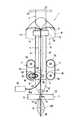
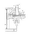
図1〜図9に基づいて、この発明による自立袋の製袋充填包装方法及びその装置の実施例を説明する。図1はこの発明による自立袋の製袋充填包装装置の一実施例の概略を示す正面図であり、図2は図1に示す自立袋の製袋充填包装装置の概略を示す側面図、図3は図2に示すA−AからE−Eに示す各断面における筒状包装フィルムの変形の過程の概略を示す断面図、図4は図1及び図2に示す自立袋の製袋充填包装装置に用いられるヘム形成手段及び折込み手段を示す斜視図、図5は図1及び図2に示す自立袋の製袋充填包装装置のヘムシール手段を含む背面図、図6は図2に示す自立袋の製袋充填包装装置の矢印F−Fで示す切断面で切断した断面図、図7は図1及び図2に示す自立袋の製袋充填包装装置の折込み手段及び横シール手段を示す側面図、図8は図1及び図2に示す自立袋の製袋充填包装装置の横シール位置における断面図、図9は図1及び図2に示す自立袋の製袋充填包装装置の横シール手段を示す正面図である。
【0021】
図1〜図9に示すこの発明による自立袋の製袋充填包装装置1は、自立袋の製袋充填を縦型の製袋充填包装として行う装置である。図1及び図2に示すように、包装フィルム10は、フォーマ9によってウエッブ状フィルム11から両側端部13,13が重ね合わされて重合部14とされた筒状包装フィルム12に形成される。フォーマ9の内部には、製袋充填包装装置における充填手段として、上方より包装物を投入するための投入筒体2が配置されており、筒状包装フィルム12は投入筒体2の外周面21に沿って案内されつつ下方に走行される。投入筒体2はその上端部22において機体フレーム28に吊り下げられた状態に配設されており、投入筒体2の上方には、図示しない計量・投入装置が配置されており、計量した量の包装物が製作される袋包装毎に投入筒体2の内部を通して投入される。
【0022】
投入筒体2の下側側方の位置において、投入筒体2との間に筒状包装フィルム12を挟んで一対の包装フィルム送り機構3が配設されている。投入筒体2の下端部23は、包装フィルム送り機構3の下端にまで延びている。また、投入筒体2は、上端部22に近い範囲では断面が円形の円形筒部24であるが、筒状包装フィルム12がフォーマ9を支持する支持フレーム29の領域を通過した後、断面形状が円形から変化する断面変化筒部25となり、断面変化筒部25より下方の部分は、断面変形が終了した断面のまま下端部23に至る異形断面筒部26となっている。後述するヘム形成手段5は、断面変化筒部25に設けられている。
【0023】
一方の包装フィルム送り機構3は、機体フレームに固定されたモータ31(図2)の出力軸32に取り付けられている駆動プーリ33と、駆動プーリ33に対して平行に配設された従動プーリ34と、駆動プーリ33及び従動プーリ34に巻き掛けられた送りベルト35とを備えている。モータ31の出力軸32の回転は、図示しない伝動機構を介して反対側の包装フィルム送り機構3に伝達されるので、一対の包装フィルム送り機構3は、筒状包装フィルム12を両側において、後述する包装動作に合わせて、間欠的に同期して下方に送ることができる。同期運転の制御性の良い電動機等の駆動源であれば、2つの駆動源によってそれぞれの包装フィルム送り機構3,3を駆動することができる。
【0024】
筒状フィルム12の内面同士を重ねた重合部14には、背貼りシール手段4によってヒートシールが施される。即ち、背貼りシール手段4は、投入筒2の前方において、重合部14を挟むように配置された一対の縦ヒートシールバー41,42から成り、縦ヒートシールバー41,42は筒状包装フィルム12の間欠走行の停止中に重合部14を挟んで、重合部14を合掌状にヒートシールする。一対の縦ヒートシールバー41,42のうち、少なくとも一方の縦ヒートシールバーが、適宜のアクチュエータによって相手側の縦ヒートシールバーに進退可能に配置されている。
【0025】
投入筒体2は、全体として、背貼りシール手段4が配設される側である前側では円筒断面形状となっているが、後側では断面変化筒部25及び異形断面筒部26では異形断面形状となっている。図3において、(a)は断面変化筒部25に至る前の図1及び図2の断面A−Aについての円形筒部24における断面図であり、(b)は断面変化筒部25の断面変化の途中の部分における断面B−Bについての断面図であり、(c)は異形断面筒部26における断面C−Cについての断面図である。
【0026】
図4に示すように、断面変化筒部25には、投入筒体2の外周面21において筒状包装フィルム12の周方向に隔置して形成された一対の突条51,51が形成されており、一対の突条51,51は、この製袋充填包装装置のヘム形成手段5の一部を構成している。筒状包装フィルム12の周囲長さは一定であるので、一対の突条51,51間及び一対の突条51,51の外側近傍の形状は筒状包装フィルム12の走行方向に向かって内側に傾斜した斜面52となっており、一対の突条51,51は、斜面52から見れば、包装フィルム12の走行方向に沿って次第に突出高さが増加する形状に形成されている。筒状包装フィルム12が投入筒体2の断面変化筒部25に沿って下方に走行するに従って、筒状包装フィルム12は、図3(b)に示すように、次第に高くなる一対の突条51,51によって一対のヘム16,16が形成される。ヘム16,16を形成するための包装フィルムの変形は、変形量としては筒状包装フィルム12の周囲長さと比較すると少ないものであり、しかも変形の速さはゆっくりとしているので、筒状包装フィルム12には重合部14を開くような過大な力が作用することがない。断面変化筒部25は異形断面筒部26に接続しており、異形断面筒部26は斜面52につながる平坦面53を有している。
【0027】
ヘム形成手段5は、更に、筒状包装フィルム12に形成された一対のヘム16,16を熱溶着する溶着手段、即ち、ヘムシール手段54を有している。ヘムシール手段54は、図5及び図6に示すように、異形断面筒部26の平坦面53に対向して配置されており、機体フレーム28に取り付けられた中央に位置する固定ヒータブロック55と固定ヒータブロック55の側方において配設されている一対の可動ヒータブロック56,56とを備えている。固定ヒータブロック55と可動ヒータブロック56,56とは、筒状包装フィルム12に形成されて下方に走行してくる一対のヘム16,16に対応して配置されている。可動ヒータブロック56,56は、固定ヒータブロック55に対して案内ロッド58によってスライド可能に支持されており、各アクチュエータ57の作動によって可動ヒータブロック56,56が固定ヒータブロック55に接近するとき、背貼りシール部15をヒートシールする場合と同様にして、図3(c)及び図6に示すように、筒状包装フィルム12に形成された一対のヘム16,16は可動ヒータブロック56,56の各シール面と固定ヒータブロック55の各シール面との間に挟み込まれて熱溶着され、ヘムシール部17が形成される。一対のヘム16,16の高さは、自立袋の底部のシールを形成する程度の低いものであり、ヘム16,16は実質的にその殆どがヘムシール部17に形成される。
【0028】
自立袋の製袋充填包装装置1において、背貼りシール部15とヘムシール部17が形成された筒状包装フィルム12は、折込み手段6によって、ヘムシール部17が形成された側において折り込まれる。折込み手段6は、図4に示すように、投入筒体2の下端部23の下方に配設されている。即ち、折込み手段6は、投入筒体2の下端部23において、突条51,51を下方に延長した位置に、包装フィルム12の走行方向に横シール手段7の直上位置まで延びるように片持ち状態に取り付けられた一対の案内プレート61,61を有している。一対の案内プレート61,61は、後述する横シール手段7が横シール部18を形成する際に筒状包装フィルム12の変形に合わせて図4でGで示す方向に弾性変形可能である。一対の案内プレート61,61の中間位置に対応して、筒状包装フィルム12の外部には、筒状包装フィルム12に対して進退可能な折込みプレート62が配置されている。
【0029】
折込みプレート62は、横シール手段7に対して包装フィルム走行方向の上流側に配設された上側折込みプレート63と、横シール手段7に対して包装フィルム走行方向の下流側に配設された設けられた下側折込みプレート64とから構成されている。上側折込みプレート63と下側折込みプレート64とは、包装フィルム走行方向に整列した位置において設けられている。上側折込みプレート63と下側折込みプレート64とは、アクチュエータ67の作用により、同期して筒状包装フィルム12に対して進退する。
【0030】
筒状包装フィルム12は、ヘムシール部17が形成された位置に対応して、一対の案内プレート61,61によって案内され、折込みプレート62が筒状包装フィルム12の外部から一対の案内プレート61,61の中間位置において筒状包装フィルム12を折り込んで、筒状包装フィルム12を図3(d)に示すように断面W字形状に折り込む。一対の案内プレート61,61は、図4に矢印Gで示す方向に容易に弾性変形可能であるので、筒状包装フィルム12の変形に合わせて変形し、横シール手段7の動作を妨げることはない。折込みプレート62を横シール手段7に対して包装フィルム走行方向の上流と下流とに分割して配置することにより、横シール手段7の上下において先行して形成された自立袋100(図1及び図2)と今回形成されようとする自立袋となる筒状包装フィルム12が確実に折り込まれる状態となり、皺の発生のない見栄えの良い横シール部18を形成することができる。
【0031】
筒状包装フィルム12を挟んで折込み手段6に対向した位置に、背貼りシール部15を挟んで一対のヘムシール部17から遠ざかる方向に引っ張ることが可能なキャッチャ手段65が配設されている。キャッチャ手段65は、特に、図7及び図8に示されているように、アクチュエータ67によって背貼りシール部15に対して進退可能であり、筒状包装フィルム12が間欠走行において、停止しているときに進出して背貼りシール部15を把持することができる一対の把持爪66,66を備えている。キャッチャ手段65に対応して、筒状包装フィルム12を背貼りシール部15の位置において内側から突っ張る突っ張りロッド69が設けられている(図4及び図7参照)。突っ張りロッド69は、案内プレート61,61と対向する側において、投入筒体2の下端部23に対して、キャッチャ手段65が配設されている位置の僅かに上方に位置まで、片持ち状に取り付けられている。突っ張りロッド69は、筒状包装フィルム12を背貼りシール部15において内側から突っ張り、キャッチャ手段65が筒状包装フィルム12の背貼りシール部15を把持しやすくする。
【0032】
キャッチャ手段65は、一対の把持爪66,66で背貼りシール部15を把持した状態で僅かに後退することにより、一対の案内プレート61,61との間で筒状包装フィルム12に張りを与える。即ち、ヘムシール部17が形成された筒状包装フィルム12は、一側において一対の案内プレート61,61により、また他側においてキャッチャ手段65によりそれぞれ互いに逆方向に付勢されるので、筒状包装フィルム12が平坦化され、筒状包装フィルム12に対して後続の横シール手段7が作動するとき、的確に横シール部18が形成される。
【0033】
横シール手段7の構造は、基本的に公知の構造である。横シール手段7は、包装物が投入筒体2を通じて投入される前に作動して、筒状包装フィルム12に横シール部18を形成する。横シール手段7は、互いに進退可能な一対の横ヒートシールバー71,72から成る。横ヒートシールバー71は、横シール部18をその中間位置において切断するカッタ73を備えており、横ヒートシールバー72には、カッタ73が入り込む溝74が形成されている(図1、図9参照)。横ヒートシールバー71,72は、図9に示すように、機体フレーム28に支持されたアクチュエータ75の作動がリンク・レバー機構76によって互いに接近・離反する動作をし、接近したときに、図3(e)に示すように、挟まれた平坦化された筒状包装フィルム12をヒートシールし、横シール部18を形成する。同時に、カッタ73が横シール部18において切断して、袋包装体である自立袋100を完成させる。
【0034】
横シール手段7の作動を補助するため、横シール手段7と同期して作動し、且つ袋に形成される直前の筒状包装フィルム12を横方向から規制する袋規制手段77が、横シール手段7の直ぐ上方に配設されている。袋規制手段77は、筒状包装フィルム12に所定の位置まで前進したとき筒状包装フィルム12の過度の膨らみを規制し、包装物が投入されるときの筒状包装フィルム12の過剰な変形やそれに起因した破損を防止する。袋規制手段77の直ぐ上方には、筒状包装フィルム12を横方向から軽く振動を加えるように叩いて、包装物の筒状包装フィルム12内での充填率を高めるための叩き手段78が配設されている。
【0035】
背貼りシール手段4が重合部14をヒートシールすることで形成された背貼りシール部15の外側の一部15aが、カッタ手段8によって切断される。即ち、ウェブ状包装フィルム11を筒状包装フィルム12に形成する場合、包装フィルムの側端縁を正確に揃わせることが困難であるため、重合部14にはずれが生じやすい。自立袋100が完成したとき、重合部14をヒートシールした背貼りシール部15は自立袋100の自立状態では上方に位置するので、ずれが生じた状態でヒートシールされた背貼りシール部15のままでは、自立袋100としての見栄えが良くない。そのため、背貼りシール手段4の直ぐ下方に、背貼りシール部15の外側の一部15aを切断するカッタ手段8が配設されている(図1,図2,図5及び図6参照)。カッタ手段8は、一方の包装フィルム送り機構3の駆動プーリ33と同軸に配設された駆動輪81と駆動輪81からチェーン82を介して駆動される回転刃83と、回転刃83に対向して縦ヒートシール部15を挟んで配置された、受けローラ84とから成る。切断された一部15aは、カッタ手段8に近接して配設された吸引筒85によって吸引されて回収される。筒状包装フィルム12を走行させる包装フィルム送り機構3を駆動する動力源の出力の一部を利用してカッタ手段8を駆動することにより、カッタ手段8を駆動する専用の駆動機構を設ける必要がなくなるので、製袋充填包装装置1の構造が簡単化される。
【0036】
自立袋の製袋充填包装装置1において、折込み手段6、キャッチャ手段65、横シール手段7、及び袋規制手段77は、機体フレーム29に取り付けられた共通ベース90に配設されている。共通ベース90は、図8に示すように、筒状包装フィルム12を囲むように環状に形成されている。共通ベース90は、機体フレーム28に対して、例えば、横方向及び上下方向に設定位置を調節可能に構成して、メインテナンスやサイズ変更等に対応し易くするのが好ましい。製袋充填の後半に属する工程、即ち、折込みから横シールまでの工程、及びそのための各手段は共通ベース90に配設されているので、製袋充填包装装置1の構造が簡単化し、装置の組立、メンテナンス等の作業が簡単且つ効率化される。また、図9に示すように、製作された自立袋100は、降下ガイド95によって滑らかに案内されてコンベヤ96に載置され搬出される。
【0037】
この自立袋の製袋充填包装方法及び自立袋の製袋充填包装装置1によれば、次のようにして、製袋充填が実行される。即ち、背貼りシール工程においては、背貼りシール手段4によって、筒状包装フィルム12の重合部14をヒートシールして背張りシール部15が形成される。ヘム形成工程においては、背貼りシール手段4と対向した位置に配設されたヘム形成手段5によって、背貼りシール部15が施される部分と対向した筒状包装フィルム12の部分に筒状包装フィルム12の周方向に隔置し且つ包装フィルム走行方向に沿った一対のヘム16,16が形成される。ヘムシール工程においては、ヘムシール手段54によって、一対のヘム16,16がヒートシールされて一対のヘムシール部17,17が形成される。折込み工程においては、折込み手段6によって、筒状包装フィルム12が一対のヘムシール部17,17の周方向中間位置において内側に折り込まれる。
【0038】
充填工程においては、充填手段である投入筒体2によって、筒状包装フィルム12内に包装物が充填され、横シール工程においては、横シール手段7によって、背貼りシール部15を一端に且つ折り込まれることにより重ね合わされた一対のヘムシール部17,17を他端に置いて、筒状包装フィルム12を包装フィルム走行方向に隔置した位置において横方向にヒートシールして、先行して製作された自立袋100を完成させる横シール部18が形成されると共に、次に製作される自立袋100の横シール部18が形成される。折込み工程は、ヘム形成とヘムシール工程の後において行われる。即ち、ヘム16,16及びヘムシール部17,17の形成と折込みとを区別して、投入筒体2に関連して行われる筒状包装フィルム12の形成を変形量の少ないヘム16,16及びヘムシール部17,17の形成に限り、変形量の大きい折込み手段6による筒状包装フィルム12の折込み形成をヘム形成手段5及びヘムシール手段54よりも包装フィルム走行方向下流、即ち、投入筒体2の下方において行うようにしたので、背貼りシールが完了するまでの筒状包装フィルム12には重合部14を拡開させるような過大な力が作用することなく、背貼りシールが良好に行われる。また、投入筒体2の断面の大きさは、変形量それ自体及びその変形変化率の小さいヘム16,16の形成に応じて変化するのみであるので、投入筒体2の投入方向における断面広さの変化量とその変化率は小さく、高い充填効率が維持されると共に、包装物の投入に際して投入筒体2ないでブリッジの形成を防止することができる。
【0039】
図10は、この発明である自立袋、即ち、製袋充填包装装置によって製作された自立袋を自立状態で示す斜視図である。背貼りシール部15、ヘムシール部17,17及び横シール部18,18は、それぞれ、自立袋100の上端シール部101、底シール部102、及び側端シール部103となる。製袋充填包装によって、自立袋100は横向きに連続製作されるので、製作されたばかりの自立袋100を90度回転することによって、背貼りシール部15を上にし、ヘムシール部17,17を下にすることによって、自立状態となる。なお、折込み手段6によって折り込まれた部分は、自立袋100では、包装フィルムの外側面同士がヒートシールされていないので、包装物の充填量にも依るが、平らに開いた底部104となっている。側シール部103の縁部には、横シール手段7のカッタ73の刃形を工夫することで波形のカットを105を入れることができ、一部は切り裂き用のカットとすることができる。底側では、四隅106でも棚面に載せることができ、自立袋100の安定性を更に向上することができる。
【0040】
【発明の効果】
この発明による自立袋の製袋充填包装装置によれば、自立袋の底部を構成することになる一対のヘム及びヘムシールの形成と、包装フィルムの内側への折込みとは、別々に施され、充填過程と関連して行われる筒状包装フィルムに対する処理での筒状包装フィルムの変形が最小限に抑えられるので、重ね合わされた両端縁を広げるような力は筒状包装フィルムに作用せず、またそのような拡開作用を与えない状態で的確に包装フィルムを走行させることができる。従って、包装フィルムを筒状に維持した状態で、皺が発生せず見栄えの良い自立袋の上端部となる背貼りシールを施すことできる。
また、充填手段は、外周面で筒状包装フィルムを案内し内部を通して包装物が投入される投入筒体であり、投入筒体の断面の大きさは、変形量それ自体及びその変形変化率の小さいヘムの形成に応じて変化するのみであるので、投入筒体の投入方向における断面広さの変化量とその変化率は小さく、投入筒体の投入断面広さを充分確保して充填物の投入を効率良く行うことができると共に、充填物投入時の充填物のブリッジ現象の発生を防止することができる。また、ヘム形成手段は、投入筒体の外周面において、筒状包装フィルムの周方向に隔置し且つ包装フィルム走行方向に沿って次第に突出高さが増加する一対の突条であり、そして、折込み手段は、投入筒体の下端部よりも包装フィルム走行方向下流側に配置されており、且つ投入筒体の下端部において一対の突条を延長した位置に包装フィルム走行方向に延びる片持ち状態に取り付けられ、包装フィルムをヘムシール部において内側から案内し横シール手段が横シール部を形成する際の筒状包装フィルムの変形に合わせて弾性変形可能な一対の案内プレートと、一対の案内プレートの中間位置に対応して筒状包装フィルムの外部に配置され筒状包装フィルムに対して進退可能な折込みプレートとから構成されているので、一対の突条とそれに続く案内プレートが筒状包装フィルムにヘムの成形を行いながら筒状包装フィルムの走行を案内し、また、折込みプレートは、ヘムシール部を横シール手段が横シール部を形成する際までも内側から案内することができるので、ヘムシール部の案内及び成形を確実に行うことができる。
【図面の簡単な説明】
【図1】この発明による自立袋の製袋充填包装装置の一実施例の概略を示す正面図である。
【図2】図1に示す自立袋の製袋充填包装装置の概略を示す側面図である。
【図3】図2に示すA−AからE−Eに示す各断面における筒状包装フィルムの変形の過程の概略を示す断面図である。
【図4】図1及び図2に示す自立袋の製袋充填包装装置に用いられるヘム形成手段及び折込み手段を示す斜視図である。
【図5】図1及び図2に示す自立袋の製袋充填包装装置のヘムシール手段を含む背面図である。
【図6】図2に示す自立袋の製袋充填包装装置の矢印F−Fで示す切断面で切断した断面図である。
【図7】図1及び図2に示す自立袋の製袋充填包装装置の折込み手段及び横シール手段を示す側面図である。
【図8】図1及び図2に示す自立袋の製袋充填包装装置の横シール位置における断面図である。
【図9】図1及び図2に示す自立袋の製袋充填包装装置の横シール手段を示す正面図である。
【図10】この発明による自立袋の一例を自立状態で示す斜視図である。[0001]
BACKGROUND OF THE INVENTION
The present invention relates to a self-standing bag making and packing method and apparatus capable of producing a self-supporting bag that is packaged while filling a package continuously from a cylindrical packaging film.
[0002]
[Prior art]
Ordinary bag packages, such as pillow packages, are not self-supporting themselves, and tend to collapse unless supported by walls or other support means or by other bag packages. In particular, when the package is a loose article, the bag package is easy to fall down, so the display property is not good. In order to give the bag package a self-supporting property, it is necessary to insert a special fold such as a gusset during the formation of the bag. The bag package thus obtained also has a structure in which a horizontal seal is present at the center of the bottom, and is not necessarily stable.
[0003]
Therefore, it has been proposed to form a self-supporting bag by applying a side seal in a state where the bottom portion is folded in a W shape in cross section. Since a self-supporting bag can be displayed on a shelf or the like in a self-supporting state without using any special support means at a sales site such as retail, as a packaging form replacing plastic containers, bottles, and cans in recent years, Has attracted attention.
[0004]
Production of a conventional packaging body made of a self-supporting bag is a direction in which a web-like packaging film with a bottom folded into a W-shaped cross section is run in the transverse direction and the packaging film is crossed at positions spaced in the running direction of the packaging film. The bag is continuously manufactured by filling the package with the bag and filling the package from the top of the bag. Compared with a vertical bag-filling and packaging machine that wraps a package in a bag formed so as to form a bag while running the packaging film from top to bottom in order to run the packaging film laterally. On the other hand, since the upper part of the bag is open at the time of filling, foreign matter such as dust may enter the inside of the packaging bag.
[0005]
Therefore, as in the vertical bag making filling and packaging machine, a web-like packaging film is run from the upper side to the lower side, and a bag making filling and packaging method and a self-supporting bag for filling a package while forming the packaging film in a cylindrical shape. A bag making and filling machine has been proposed in Japanese Patent Application Laid-Open No. 11-152104. According to the bag making and filling and packaging method for self-supporting bags disclosed in this publication, first, while feeding the cylindrically formed film downward, heat-sealing both end portions where the films are overlapped, By heat-sealing the tip of the two crests opposite to the part to be sealed, the parts corresponding to the top and bottom of the free-standing bag are heat-sealed, and then the filling is put into the film. By heat-sealing the film loaded with in the horizontal direction, the portion corresponding to the side portion of the self-supporting bag is heat-sealed. The bag package manufactured by cutting the part heat-sealed in the horizontal direction becomes a self-supporting bag package when the posture is changed by 90 degrees.By forming spot welds at four locations on the side bottom of the free-standing bag, it prevents the spread of the ears in the vicinity of the side of the free-standing bag and prevents the large internal pressure from acting on the front end of the folding portion. Yes.
[0006]
Further, the self-supporting bag making and filling and packaging machine disclosed in the above publication is a first that heat-seals both end portions of the films formed in a cylindrical shape and overlapped with each other along the longitudinal direction of the film. A sealing mechanism, a folding mechanism that is disposed on the opposite side of the first sealing mechanism across the film, and that folds a part of the film inward, and the tip portions of two peaks formed on the film by the folding mechanism. A second heat sealing mechanism for heat-sealing along the longitudinal direction of the film, and an insertion inserted into the bag for charging the filling into the film heat-sealed by the first sealing mechanism and the second heat sealing mechanism A pipe, and a third sealing mechanism that is disposed below the charging pipe and heat-seals the film in the horizontal direction and cuts the heat-sealed portion. The portion corresponding to the upper end portion of the standing bag is heat-sealed, the portion corresponding to the bottom portion of the self-standing bag is heat-sealed by the second heat sealing mechanism, and the filling material is charged into the film by the charging pipe. A self-supporting bag is continuously manufactured by heat-sealing a part with a 3rd sealing mechanism in a horizontal direction, and cut | disconnecting. That is, when a self-supporting bag is continuously manufactured by a vertical bag-making filling and packaging machine, the packaging film is run so that the completed bag is turned sideways.
[0007]
According to the bag making and filling packaging of the self-supporting bag described in the above publication, in order to form a portion corresponding to the bottom of the self-supporting bag, on the opposite side of the film with respect to the first sealing mechanism, A folding mechanism that folds a part inside is arranged. Since the folding mechanism uses a pressing plate and a presser plate, such a folding mechanism opens the film immediately after being formed into a cylindrical shape in the circumferential direction when folding the film inward, and both sides of the stacked state The structure tends to cause an effect of separating the end portions.
[0008]
When the folding mechanism is arranged on the opposite side of the film with respect to the first sealing mechanism, the cross-sectional area of the tubular film is folded at the position where the charging pipe for charging is inserted. It is already narrowed by the amount folded by the mechanism. Therefore, the pipe diameter of the input pipe that can be inserted into the cylindrical packaging film is reduced, and it is easy to be restricted by the type and timing of the charged filler when the filler is charged. When the pipe diameter of the input pipe is small, a bridging phenomenon is likely to occur when the loose article is packed in the input pipe when the loose article is packaged.
[0009]
[Problems to be solved by the invention]
ThereforeTheAbout bag making filling and packaging equipment that manufactures standing bags,Regardless of the crushing deformation of the cylindrical packaging film due to the formation of the horizontal seal part,Self-supporting bagEnhancedA pair of hems and their seals that will form the bottomThe formation of the part and the guidance of the hem seal part thus formed are performed accurately.Based on the idea, the cylindrical force is applied to widen the overlapping edges by minimizing the deformation of the cylindrical packaging film in the treatment of the cylindrical packaging film in connection with the filling process. Applying a back-sealing seal at the upper end of the self-standing bag without acting on the packaging film and giving such a spreading action, accurately sealing the packaging film while maintaining a cylindrical shape, and filling There is a problem to be solved in terms of preventing the occurrence of the bridging phenomenon of the filling material by sufficiently securing the cross-sectional area of the charged material when it is put into the packaging film.
[0010]
[Means for Solving the Problems]
An object of the present invention is to solve the above-described problem, and to form a bottom seal portion that can expand the bottom portion.CompleteSelf-standing bagsThe verticalMold bag filling and packagingPlaceAbout making byRegardless of the crushing deformation of the cylindrical packaging film due to the formation of the lateral seal part, the formation of a pair of hem seal parts that will constitute the reinforced bottom part of the self-supporting bag and the guidance of the hem seal part are performed accurately,Enables automatic and continuous production without expanding the packaging film formed on the tubular film,wrinklePrevent the occurrence ofThe hem seal part with good filling efficiency and accuracy was formed, and the strength of the bottom part was reinforced.A self-supporting bag that can produce a good-looking self-supporting bag and that can prevent the occurrence of bridging when filling the bag.DressIs to provide a position.
[0012]
The present invention provides a back-sealing seal means for forming a back-sealing seal portion by heat-sealing both side ends overlapped in a palm shape along the packaging film traveling direction of the cylindrical packaging film, and sandwiching the cylindrical packaging film Hem forming means disposed at a position opposed to the back sticking sealing means, spaced apart in the circumferential direction of the tubular packaging film and forming a pair of hems along the packaging film running direction, the hem forming means A hem seal means disposed in the downstream of the packaging film traveling direction to heat-seal the pair of hems on the inner surface of the cylindrical packaging film to form a pair of hem seal portions, and the packaging with respect to the hem seal means Folding means that is arranged downstream of the film running direction and folds the tubular packaging film inwardly at a circumferential intermediate position between the pair of hem seal portions. The filling means for filling the tubular packaging film with the package, and the pair of hem seal parts overlapped by folding the back-sealed seal part at one end and the folding means at the other end. A horizontal sealing means for forming a horizontal sealing portion between the cylindrical packaging film and a self-standing bag formed subsequently by heat-sealing in a lateral direction at a position spaced in the packaging film traveling direction, and the horizontal sealing portion Is left in a state where the film outer surfaces facing each other of the cylindrical packaging film folded inward by the folding means are not heat-sealed, and the back-sealed seal portion, the hem seal portion, and the lateral seal PartBut,An upper end seal portion, a bottom seal portion and a side end seal portion of each of the self-supporting bags;The filling means is an input cylinder body that guides the cylindrical packaging film on the outer peripheral surface and into which the package is input, and the hem forming means is provided on the outer peripheral surface of the input cylinder body, A pair of ridges spaced apart in the circumferential direction of the tubular packaging film and gradually increasing in the projecting height along the traveling direction of the packaging film, and further, the folding means is from a lower end of the charging cylinder Is disposed downstream of the packaging film in the traveling direction, and is attached in a cantilever state extending in the packaging film traveling direction to a position where a pair of the protrusions are extended at the lower end of the charging cylinder, A pair of guide plates that are elastically deformable in accordance with the deformation of the tubular packaging film when the film is guided from the inside in the hem seal portion and the lateral seal means forms the lateral seal portion. And bets, and a retractable folding plate to the outside to be arranged the tubular wrapping film of the pair of guiding the intermediate position the tubular in response to the packaging film of the plateThe present invention relates to a bag making filling and packaging apparatus for self-standing bags.
[0013]
This free standing bagSelfAccording to the standing bag making, filling and packaging equipmentThe backThe back seal part is formed by heat-sealing the both side ends overlapped along the packaging film running direction of the cylindrical packaging film by the sticking sealing means.The backThe wrapping film is spaced apart in the circumferential direction of the tubular wrapping film on the portion of the tubular wrapping film facing the portion where the back sticking seal portion is applied by the hem forming means disposed at a position facing the sticking sealing means. A pair of hems along the running direction is formed. FA pair of hems are heat sealed by the mussel means to form a hem seal portion.FoldThe cylindrical packaging film in which the hem seal portion is formed is folded inward at the circumferential intermediate position between the pair of hems.. ChargeThe packing is filled in the cylindrical packaging film by the filling means.,sideWith the sealing means, the back-sealed seal part is placed at one end and a pair of hem seal parts overlapped by being folded are placed at the other end, and the cylindrical packaging film is heat-sealed in the lateral direction at a position spaced in the packaging film running direction. Thus, a lateral seal portion is formed between the self-standing bags formed subsequently.Also tubeSince only a part of the cylindrical packaging film is slightly deformed, the deformation amount of the cylindrical packaging film is small, and therefore the force exerted on the cylindrical packaging film due to the formation of heme is small. Also,Tubular packaging filmInsertMihaHem formation and hem sealAfter, i.e.Since the hem forming means and the fold sealing means disposed downstream of the hem seal means in the direction of travel of the packaging film are performed, the back-sealed seal is maintained while maintaining the shape of the cylindrical packaging film without expanding the overlapped portion. Applied. Moreover, since the magnitude | size of the cross section of a cylindrical packaging film is not overly narrowed until folding is performed after heme formation, the packing efficiency in the cylindrical packaging film increases.
[0014]
thisBag making and fillingDressThe back-sealed seal portion, the hem seal portion and the lateral seal portion are respectivelyBeforeSelf-standing bag top seal and bottom sealas well asSide end seal andIsThe That is, since the self-supporting bag is continuously manufactured in the horizontal direction by the bag-filling packaging, by rotating the bag package just manufactured by 90 degrees, the back-sealed seal part is turned up and the hem seal part is turned down. It becomes a self-supporting bag.The seal part is left in a state where the film outer surfaces facing each other of the cylindrical packaging film folded inward by the folding means are not heat-sealed, and the back-sealed seal part, the hem seal part, and the lateral seal part are independent. Since the top seal part, bottom seal part and side end seal part of the bag are used, the parts folded inward by the folding means are in a state where the film outer surfaces facing each other are not heat-sealed and the package is filled The bottom seal is reinforced with a hem seal so that it can stand on its own and can generate wrinkles. A self-supporting bag that looks good can be manufactured automatically.
[0015]
Further, in the above bag making filling and packaging apparatus for self-supporting bags, the filling means guides the cylindrical packaging film on the outer peripheral surface, and the package is inserted through the inside.ThrowA pair of hem forming means spaced apart in the circumferential direction of the cylindrical packaging film on the outer circumferential surface of the charging cylinder and gradually increasing in projecting height along the traveling direction of the packaging film. It is a ridge. That is, the formation of hem, Input cylinderAs the cylindrical wrapping film is guided by the body, it is sequentially formed by a pair of ridges, and the amount of deformation of the cylindrical wrapping film due to the ridges for forming the hem is small. Excessive force does not act on the packaging film.The filling means may be a charging cylinder whose cross section changes from a cylindrical shape to an irregular shape as the packaging film travel direction is traced.
[0016]
In the above self-standing bag making and filling and packaging apparatus, the folding means is disposed on the downstream side in the packaging film running direction from the lower end of the charging cylinder.Has been. The folding means is attached in a cantilever state extending in the traveling direction of the packaging film at a position where the protrusion is extended at the lower end of the charging cylinder, and guides the packaging film from the inside at the hem seal portion. A pair of guide plates that can be elastically deformed in accordance with deformation of the cylindrical packaging film when the horizontal sealing means forms the horizontal seal portion, and the cylindrical packaging corresponding to an intermediate position between the pair of guide plates It is composed of a folding plate that is arranged outside the film and can be moved back and forth with respect to the tubular packaging film.Has been. The cylindrical packaging film is securely guided by the pair of guide plates corresponding to the position where the hem is formed, and the folding plate is inserted from the outside of the cylindrical packaging film at the intermediate position of the pair of guide plates. By folding, the cylindrical packaging film is folded into a W-shaped cross section. Since the pair of guide plates can be elastically deformed, they are deformed in accordance with the deformation of the cylindrical packaging film, and the horizontal sealing means does not hinder the operation of forming the horizontal sealing portion. Further, the folding plate has an upper folding plate disposed on the upstream side in the packaging film running direction with respect to the lateral sealing means, and the packaging with respect to the lateral sealing means at a position aligned with the upper folding plate. Consists of a lower folding plate disposed downstream of the film running directionCanThe By arranging the folding plate separately from upstream and downstream in the direction of travel of the packaging film with respect to the lateral sealing means, the state that the cylindrical packaging film is securely folded above and below the lateral sealing means during lateral sealing is maintained. A good-looking side seal without sagging and wrinkles is formed.
[0017]
aboveIn a self-standing bag making and filling and packaging apparatus, a catcher means for sandwiching the back-sealed seal portion and pulling it away from the pair of hem seal portions at a position facing the folding means with the tubular packaging film interposed therebetweenTheArrangementAndCorresponding to the catcher means, a tension rod that stretches the tubular packaging film from the inside at the position of the back-sealed seal portionTheEstablishmentCanThe The cylindrical packaging film formed with the hem seal is urged in opposite directions by a pair of guide plates on one side where folding is performed and by a catcher means on the other side, so that the cylindrical packaging film is flattened. And a horizontal seal is accurately formed with respect to the cylindrical packaging film. When a tension rod that stretches the cylindrical packaging film from the inside at the position of the back sticking seal portion is provided, the catcher means can easily sandwich the back sticking seal portion that is stretched from the inside by the tension rod.
[0018]
Also thisSelfStanding bagManufactured by the bag filling and packing equipmentThe self-supporting bag has an upper end seal portion formed by heat-sealing the upper ends of the packaging films that are heat-sealed between the inner surfaces, and both end portions of the packaging films are folded inward from the bottom to the inside. The film outer surfaces facing each other in the folded portion are left in a state where they are not heat sealed, and are formed on the side end seal portion formed by heat sealing between the inner surfaces of the packaging film, and the folding lower end edge of the folded portion. The hem comprises a bottom seal portion formed by heat sealing the inner surfaces to each other.
[0019]
According to this self-supporting bag, the side end seal portion opens according to the filling of the package at the film outer surfaces that are not heat-sealed, and the bottom portion of the self-supporting bag expands, so that a sufficient amount of filling is provided in the self-supporting bag. Can be secured. In addition, since the bottom seal portion is reinforced by the hem seal portion, it can be stably independent.
[0020]
DETAILED DESCRIPTION OF THE INVENTION
Based on FIGS. 1-9, the Example of the bag making filling packaging method of the self-supporting bag by this invention and its apparatus are demonstrated. FIG. 1 is a front view showing an outline of an embodiment of a bag making filling and packaging apparatus for self-standing bags according to the present invention, and FIG. 2 is a side view showing an outline of the bag making filling and packaging apparatus for self-standing bags shown in FIG. 3 is a cross-sectional view showing an outline of the process of deformation of the tubular packaging film in each cross section shown in AA to EE shown in FIG. 2, and FIG. 4 is a bag-filling package for the self-supporting bag shown in FIGS. FIG. 5 is a rear view including the hem sealing means of the self-standing bag making and packing apparatus shown in FIGS. 1 and 2, and FIG. 6 is a self-standing bag shown in FIG. Sectional drawing cut | disconnected by the cut surface shown by the arrow FF of the bag making filling packaging apparatus of FIG. 7, FIG. 7 is a side view which shows the folding means and side seal means of the bag making filling packaging apparatus of the self-supporting bag shown in FIG.1 and FIG.2. FIG. 8 is a cross-sectional view of the self-standing bag making and filling apparatus shown in FIGS. Figure 9 is a front view showing the horizontal sealing means bag manufacturing filling and packaging apparatus of self-supporting bag shown in FIGS.
[0021]
A bag making and filling
[0022]
A pair of packaging
[0023]
One wrapping
[0024]
Of the tubular film 12The inner surfaces overlap each
[0025]
The
[0026]
As shown in FIG. 4, the cross-section changing
[0027]
The hem forming means 5 further includes a welding means for thermally welding a pair of
[0028]
In the self-standing bag making and filling and
[0029]
The
[0030]
The
[0031]
A catcher means 65 that can be pulled away from the pair of
[0032]
The catcher means 65 slightly retracts in a state where the back-sealed
[0033]
The structure of the lateral seal means 7 is basically a known structure. The horizontal sealing means 7 operates before the package is input through the
[0034]
In order to assist the operation of the lateral sealing means 7, a bag regulating means 77 that operates in synchronization with the lateral sealing means 7 and regulates the
[0035]
A
[0036]
In the self-standing bag making and filling and
[0037]
According to the bag making filling and packaging method for self-supporting bags and the bag making filling and
[0038]
In the filling process, the package is filled in the
[0039]
FIG. 10 shows the present invention.Self-supporting bagsIt is a perspective view which shows the self-supporting bag manufactured by the bag filling packaging apparatus in a self-supporting state. The back-sealed
[0040]
【The invention's effect】
Bag making and filling of self-standing bags according to the present inventionDressAccording to the installation, the formation of the pair of hems and hem seals that constitute the bottom of the self-supporting bag and the folding into the inner side of the packaging film are performed separately and are performed in association with the filling process Since the deformation of the cylindrical packaging film during the processing of the film is minimized, the force that widens the overlapping edges does not act on the cylindrical packaging film and does not give such a spreading action The packaging film can be traveled accurately. Therefore, in the state where the packaging film is maintained in a cylindrical shape, it is possible to provide a back-sticking seal that becomes the upper end portion of a self-supporting bag that does not generate wrinkles and has a good appearance.
Further, the filling means is an input cylinder that guides the cylindrical packaging film on the outer peripheral surface and into which the package is introduced through the inside,The size of the cross-section of the input cylinder only changes in accordance with the deformation amount itself and the formation of hem with a small deformation change rate. The rate is small, and the charging section can be sufficiently charged by sufficiently securing the charging cross-sectional area of the charging cylinder, and the bridging phenomenon of the packing at the time of charging can be prevented.Further, the hem forming means is a pair of protrusions that are spaced apart in the circumferential direction of the cylindrical packaging film on the outer circumferential surface of the charging cylinder and the projection height gradually increases along the packaging film traveling direction, and The folding means is disposed on the downstream side in the packaging film traveling direction from the lower end portion of the charging cylinder, and cantilevered in the packaging film traveling direction at a position where a pair of protrusions are extended at the lower end of the charging cylinder. A pair of guide plates that are elastically deformable in accordance with the deformation of the cylindrical packaging film when the packaging film is guided from the inside in the hem seal portion and the lateral sealing means forms the lateral seal portion, and a pair of guide plates Since it is composed of a folding plate that is arranged outside the cylindrical packaging film corresponding to the intermediate position and can be moved back and forth with respect to the cylindrical packaging film, The guide plate guides the travel of the tubular wrapping film while forming the hem on the tubular wrapping film, and the folding plate guides the hem seal part from the inside even when the transverse seal means forms the transverse seal part. Thus, the hem seal portion can be guided and molded reliably.
[Brief description of the drawings]
FIG. 1 is a front view showing an outline of an embodiment of a self-standing bag making and filling and packaging apparatus according to the present invention.
FIG. 2 is a side view showing an outline of the self-standing bag making and packing apparatus shown in FIG. 1;
3 is a cross-sectional view schematically showing a process of deformation of the cylindrical packaging film in each cross section shown in AA to EE shown in FIG. 2;
4 is a perspective view showing hem forming means and folding means used in the self-standing bag making and filling and packaging apparatus shown in FIGS. 1 and 2. FIG.
FIG. 5 is a rear view including a hem seal means of the bag making and filling and packaging apparatus for a self-supporting bag shown in FIGS. 1 and 2;
6 is a cross-sectional view of the self-standing bag making and filling and packaging apparatus shown in FIG.
7 is a side view showing folding means and lateral sealing means of the self-standing bag making and filling and packaging apparatus shown in FIGS. 1 and 2. FIG.
FIG. 8 is a cross-sectional view of the self-standing bag making and filling and packaging apparatus shown in FIGS.
FIG. 9 is a front view showing a lateral seal means of the bag making filling and packaging apparatus for a self-supporting bag shown in FIGS. 1 and 2;
FIG. 10 is an illustration of the present invention.SelfStanding bagExampleIt is a perspective view which shows this in a self-supporting state.
Claims (4)
Translated fromJapanese前記横シール部は、前記折込み手段で内側に折り込まれた前記筒状包装フィルムの互いに対向するフィルム外側面同士がヒートシールされていない状態で残されており、前記背貼りシール部、前記ヘムシール部及び前記横シール部が、それぞれ前記自立袋の上端シール部、底シール部及び側端シール部となっており、
前記充填手段は、外周面で前記筒状包装フィルムを案内し内部を通して前記包装物が投入される投入筒体であり、前記ヘム形成手段は、前記投入筒体の外周面において、前記筒状包装フィルムの周方向に隔置し且つ前記包装フィルム走行方向に沿って次第に突出高さが増加する一対の突条であり、更に、
前記折込み手段は、前記投入筒体の下端部よりも前記包装フィルム走行方向下流側に配置されており、且つ前記投入筒体の前記下端部において一対の前記突条を延長した位置に前記包装フィルム走行方向に延びる片持ち状態に取り付けられ、前記包装フィルムを前記ヘムシール部において内側から案内し前記横シール手段が前記横シール部を形成する際の前記筒状包装フィルムの変形に合わせて弾性変形可能な一対の案内プレートと、前記一対の案内プレートの中間位置に対応して前記筒状包装フィルムの外部に配置され前記筒状包装フィルムに対して進退可能な折込みプレートとから構成されていることから成る自立袋の製袋充填包装装置。Back-sealed sealing means for forming a back-sealed seal portion by heat-sealing both side ends overlapped in a palm shape along the packaging film traveling direction of the cylindrical packaging film, and the back-sealed seal sandwiching the tubular packaging film Hem forming means disposed at a position facing the means and spaced apart in the circumferential direction of the cylindrical packaging film and forming a pair of hems along the packaging film traveling direction, with respect to the hem forming means A hem seal means disposed in the downstream of the packaging film traveling direction to heat-seal the pair of hems on the inner surface of the cylindrical packaging film to form a pair of hem seal portions; Folding means for folding the cylindrical packaging film inwardly at a circumferential intermediate position between the pair of hem seal portions, the cylindrical package Filling means for filling a package with a package, and the tubular packaging film with the back-sealed seal part at one end and the pair of hem seal parts overlapped by being folded by the folding means at the other end A horizontal sealing means for forming a horizontal seal portion between the bag and the self-supporting bag formed subsequently by heat sealing in the horizontal direction at a position spaced in the packaging film traveling direction,
The lateral seal part is left in a state where the film outer surfaces facing each other of the tubular packaging film folded inward by the folding means are not heat sealed, the back-sealed seal part, the hem seal part And the lateral seal partis an upper end seal part, a bottom seal part and a side end seal part of the self-standing bag, respectively.
The filling means is an input cylinder body that guides the cylindrical packaging film on an outer peripheral surface and into which the package is inserted, and the hem forming means is formed on the outer peripheral surface of the input cylinder body. A pair of protrusions spaced apart in the circumferential direction of the film and gradually increasing in height along the traveling direction of the packaging film;
The folding means is disposed downstream of the lower end portion of the charging cylinder in the packaging film traveling direction, and the packaging film is extended to a position where the pair of protrusions are extended at the lower edge of the charging cylinder. Mounted in a cantilever state extending in the traveling direction, the packaging film is guided from the inside in the hem seal portion, and can be elastically deformed in accordance with the deformation of the cylindrical packaging film when the lateral seal means forms the lateral seal portion A pair of guide plates, and a folding plate disposed outside the cylindrical packaging film corresponding to an intermediate position between the pair of guide plates and capable of moving forward and backward with respect to the cylindrical packaging film. A self-supporting bag making and filling and packing device.
Priority Applications (1)
| Application Number | Priority Date | Filing Date | Title |
|---|---|---|---|
| JP2000022844AJP4436517B2 (en) | 2000-01-31 | 2000-01-31 | Self-standing bag making and filling and packaging equipment |
Applications Claiming Priority (1)
| Application Number | Priority Date | Filing Date | Title |
|---|---|---|---|
| JP2000022844AJP4436517B2 (en) | 2000-01-31 | 2000-01-31 | Self-standing bag making and filling and packaging equipment |
Publications (3)
| Publication Number | Publication Date |
|---|---|
| JP2001206307A JP2001206307A (en) | 2001-07-31 |
| JP2001206307A5 JP2001206307A5 (en) | 2007-03-15 |
| JP4436517B2true JP4436517B2 (en) | 2010-03-24 |
Family
ID=18549083
Family Applications (1)
| Application Number | Title | Priority Date | Filing Date |
|---|---|---|---|
| JP2000022844AExpired - Fee RelatedJP4436517B2 (en) | 2000-01-31 | 2000-01-31 | Self-standing bag making and filling and packaging equipment |
Country Status (1)
| Country | Link |
|---|---|
| JP (1) | JP4436517B2 (en) |
Families Citing this family (10)
| Publication number | Priority date | Publication date | Assignee | Title |
|---|---|---|---|---|
| DE10149476A1 (en)* | 2001-10-08 | 2003-04-17 | Rovema Gmbh | Tubular bag machine for producing edge-welded tubular bags |
| US6679034B2 (en)* | 2002-03-18 | 2004-01-20 | Recot, Inc. | Vertical stand-up pouch quick change module |
| US6722106B2 (en)* | 2002-03-18 | 2004-04-20 | Recot, Inc. | Vertical stand-up pouch |
| US7299608B2 (en) | 2002-03-18 | 2007-11-27 | Frito-Lay North America, Inc. | Quick change module with adjustable former attachments |
| US7254930B2 (en) | 2002-03-18 | 2007-08-14 | Frito-Lay North America, Inc. | Stationary tucker bar mechanism |
| US7516596B2 (en) | 2002-03-18 | 2009-04-14 | Frito-Lay North America, Inc. | Bandolier format packaging |
| US7552574B2 (en) | 2002-03-18 | 2009-06-30 | Frito-Lay North America, Inc. | Variable tension gusseting system |
| JP5478414B2 (en)* | 2010-08-13 | 2014-04-23 | 株式会社東京自働機械製作所 | Packaging bags and vertical bag making filling and packaging equipment |
| JP5859482B2 (en)* | 2013-05-21 | 2016-02-10 | 株式会社フジキカイ | Horizontal bag making and filling machine |
| CN108190129B (en)* | 2018-01-30 | 2024-03-26 | 安徽永成电子机械技术有限公司 | Automatic line is with segmentation hem conveyer |
Family Cites Families (7)
| Publication number | Priority date | Publication date | Assignee | Title |
|---|---|---|---|---|
| JPS5659506U (en)* | 1979-10-13 | 1981-05-21 | ||
| JPS58136406U (en)* | 1982-03-10 | 1983-09-13 | 株式会社東京自働機械製作所 | Gusset packaging equipment |
| JPS5937109A (en)* | 1982-08-19 | 1984-02-29 | 株式会社 川島製作所 | Manufacture of erected package by longitudinal type bagging packer |
| JPS62165202U (en)* | 1986-04-07 | 1987-10-20 | ||
| JP3468558B2 (en)* | 1993-10-15 | 2003-11-17 | 株式会社川島製作所 | Vertical four-sided seal bag filling and packaging machine |
| JPH10297648A (en)* | 1997-04-24 | 1998-11-10 | Aarand:Kk | Bag for leaving article being dipped |
| JP3942251B2 (en)* | 1997-09-18 | 2007-07-11 | ピジョン株式会社 | Baby bottle disinfection container |
- 2000
- 2000-01-31JPJP2000022844Apatent/JP4436517B2/ennot_activeExpired - Fee Related
Also Published As
| Publication number | Publication date |
|---|---|
| JP2001206307A (en) | 2001-07-31 |
Similar Documents
| Publication | Publication Date | Title |
|---|---|---|
| JP5433000B2 (en) | Vertical filling and packaging machine and method for producing contents-containing packaging bag | |
| US7908826B2 (en) | Method and apparatus for providing end seals on vertical stand-up packages | |
| CA1150613A (en) | Device for manufacturing packages filled with liquid | |
| KR101242344B1 (en) | Vertical stand-up pouch with zipper seal | |
| US3852937A (en) | Shrink-wrapping method and apparatus | |
| JP2000226005A (en) | Horizontal machine for forming, filling and sealing | |
| JP5246428B2 (en) | Bag making and packaging machine | |
| JP2004505807A (en) | Method and apparatus for making reclosable plastic bags using pre-mounted slider-operated fasteners | |
| AU2920499A (en) | Device for producing re-sealable tubular packaging bags | |
| JP4436517B2 (en) | Self-standing bag making and filling and packaging equipment | |
| JPWO2006106932A1 (en) | Self-supporting pillow pouch packaging device, manufacturing method and manufacturing apparatus | |
| JP2630974B2 (en) | Filter bag matching device for continuous production of filter bags | |
| JP6667198B2 (en) | Band-shaped packaging material supply device in bag making and packaging machine | |
| JPH10305806A (en) | Cylindrical sheet shaping apparatus | |
| JPH0885505A (en) | Bag-making/filling/packaging device and packaging bag | |
| JP2011246186A (en) | Method and device for making manufactured bag to have flat shape, for vertical type bag manufacturing/filling/packaging machine | |
| JP2002316367A (en) | Apparatus for fitting zipper strip and method for preparing zippered bag | |
| JP4875877B2 (en) | Bag-making device with hem | |
| JP4651459B2 (en) | Vertical bag making and filling machine and bag making and filling method | |
| JP3969783B2 (en) | Bag making filling and packaging machine | |
| JP6407823B2 (en) | Vertical bag making filling and packaging machine for square bottom bags | |
| JP7719497B2 (en) | Bag making and packaging equipment | |
| CN223407570U (en) | Vertical zipper packaging bag making machine | |
| JPH08244705A (en) | Vertical bag-making/filling/packaging method for loose article | |
| WO1996011138A2 (en) | Manufacture and filling of plastics bags |
Legal Events
| Date | Code | Title | Description |
|---|---|---|---|
| A521 | Written amendment | Free format text:JAPANESE INTERMEDIATE CODE: A523 Effective date:20070131 | |
| A621 | Written request for application examination | Free format text:JAPANESE INTERMEDIATE CODE: A621 Effective date:20070131 | |
| A977 | Report on retrieval | Free format text:JAPANESE INTERMEDIATE CODE: A971007 Effective date:20081017 | |
| A131 | Notification of reasons for refusal | Free format text:JAPANESE INTERMEDIATE CODE: A131 Effective date:20081202 | |
| A521 | Written amendment | Free format text:JAPANESE INTERMEDIATE CODE: A523 Effective date:20090202 | |
| A02 | Decision of refusal | Free format text:JAPANESE INTERMEDIATE CODE: A02 Effective date:20090714 | |
| A521 | Written amendment | Free format text:JAPANESE INTERMEDIATE CODE: A523 Effective date:20091013 | |
| A911 | Transfer of reconsideration by examiner before appeal (zenchi) | Free format text:JAPANESE INTERMEDIATE CODE: A911 Effective date:20091022 | |
| TRDD | Decision of grant or rejection written | ||
| A01 | Written decision to grant a patent or to grant a registration (utility model) | Free format text:JAPANESE INTERMEDIATE CODE: A01 Effective date:20091222 | |
| A01 | Written decision to grant a patent or to grant a registration (utility model) | Free format text:JAPANESE INTERMEDIATE CODE: A01 | |
| A61 | First payment of annual fees (during grant procedure) | Free format text:JAPANESE INTERMEDIATE CODE: A61 Effective date:20091228 | |
| R150 | Certificate of patent or registration of utility model | Ref document number:4436517 Country of ref document:JP Free format text:JAPANESE INTERMEDIATE CODE: R150 Free format text:JAPANESE INTERMEDIATE CODE: R150 | |
| FPAY | Renewal fee payment (event date is renewal date of database) | Free format text:PAYMENT UNTIL: 20130108 Year of fee payment:3 | |
| FPAY | Renewal fee payment (event date is renewal date of database) | Free format text:PAYMENT UNTIL: 20130108 Year of fee payment:3 | |
| FPAY | Renewal fee payment (event date is renewal date of database) | Free format text:PAYMENT UNTIL: 20160108 Year of fee payment:6 | |
| R250 | Receipt of annual fees | Free format text:JAPANESE INTERMEDIATE CODE: R250 | |
| R250 | Receipt of annual fees | Free format text:JAPANESE INTERMEDIATE CODE: R250 | |
| R250 | Receipt of annual fees | Free format text:JAPANESE INTERMEDIATE CODE: R250 | |
| LAPS | Cancellation because of no payment of annual fees |