JP4436073B2 - Railway vehicle operation method and operation system - Google Patents
Railway vehicle operation method and operation systemDownload PDFInfo
- Publication number
- JP4436073B2 JP4436073B2JP2003159443AJP2003159443AJP4436073B2JP 4436073 B2JP4436073 B2JP 4436073B2JP 2003159443 AJP2003159443 AJP 2003159443AJP 2003159443 AJP2003159443 AJP 2003159443AJP 4436073 B2JP4436073 B2JP 4436073B2
- Authority
- JP
- Japan
- Prior art keywords
- vehicle
- railway
- stop
- station
- vehicles
- Prior art date
- Legal status (The legal status is an assumption and is not a legal conclusion. Google has not performed a legal analysis and makes no representation as to the accuracy of the status listed.)
- Expired - Lifetime
Links
- 238000000034methodMethods0.000titleclaimsdescription18
- XEEYBQQBJWHFJM-UHFFFAOYSA-NIronChemical compound[Fe]XEEYBQQBJWHFJM-UHFFFAOYSA-N0.000claims2
- 229910052742ironInorganic materials0.000claims1
- 238000004891communicationMethods0.000description25
- 238000010586diagramMethods0.000description8
- 230000001133accelerationEffects0.000description5
- 230000015572biosynthetic processEffects0.000description3
- 230000008859changeEffects0.000description3
- 238000005516engineering processMethods0.000description3
- 239000002699waste materialSubstances0.000description3
- 230000008901benefitEffects0.000description2
- 238000011017operating methodMethods0.000description2
- 238000013459approachMethods0.000description1
- 238000011161developmentMethods0.000description1
- 230000000694effectsEffects0.000description1
- 238000012986modificationMethods0.000description1
- 230000004048modificationEffects0.000description1
- 238000005192partitionMethods0.000description1
- 230000008569processEffects0.000description1
- 238000012545processingMethods0.000description1
- 230000004044responseEffects0.000description1
Images


Landscapes
- Electric Propulsion And Braking For Vehicles (AREA)
- Train Traffic Observation, Control, And Security (AREA)
Description
Translated fromJapanese【0001】
【発明の属する技術分野】
本発明は、APMやLRT等の小型で軽量な鉄道車両システムに用いるのに適した、軌道系自動運転の新交通システムの運行方法及び運行システムに関する。
【0002】
【従来の技術】
近年、例えばLRT(Light Rail Transit)等と称される比較的軽量の鉄道車両が開発・研究されている。
このような小型で軽量な鉄道車両は、ゴー&ストップが容易であるため、一般に、連結なしの単独車両、或いは、比較的少ない車両を連結してなる編成車両として、各駅間を比較的短く設定された路線で運行するのに適している。
【0003】
ところで、LRT等の小型で軽量な鉄道車両に限らないが、一般に、鉄道車両では、乗客の大量輸送を効率よく且つ安全に行なうことが重要な課題である。
鉄道の場合、車両の連結数を増やすことで大量輸送を行なえるようにすることができるが、乗客数のピーク時に合せて車両の連結数を設定すれば乗客数の少ない場合に無駄な連結数の車両を走らせてしまうことになり効率が悪い。また、乗客数に応じて車両の連結数を変更することも考えられるが、作業負担が大きく現実的ではない。そこで、一般には車両の連結数を一定としておき、乗客数に応じた頻度で車両を運行することで、大量輸送を効率よく行なえるようにしている。
【0004】
しかし、乗客数に応じて車両の運行頻度を高めると、路線上を走行する車両の密度が高くなって、先行車両(連結された編成車両なら先行車両群)と後続車両(後続車両群)との車間距離が短くなるため、安全性を確保できるように、車両の運行を高精度で制御しなくてはならない。
そこで、鉄道車両において、安全性を確保しながら高密度で運行できるようにする技術が提案されている。
【0005】
例えば、特許文献1には、循環路線内に設けられた駅間の同一線路上に同じ方向へ走行する少なくとも2両以上の鉄道車両の運行効率を良くするため、その区間における車両両数や運行状況を各々の車両が把握して、各々の車両の目標保安速度を決定し、駅間での鉄道車両を高密度に運行できるようにする技術が提案されている。
【0006】
さらに詳細に説明すれば、特許文献1の技術では、先頭車両の前面と後尾車両の後面にそれぞれ設けた車両自身の車両間距離検出器により、前方及び後方の検出された信号を運行情報として通信装置を介して地上計算機へ伝送した後、駅間に位置する複数の車両の混雑度合いを逐次計算し、その混雑度信号を各々の車両に伝送し、前方及び後方における車両間距離が規定値よりも小さくなったならば車両混雑度係数を加味して、目標保安速度の減速度値を可変に調整すると共に、それらの走行パタ−ンを設定するようにしている。これにより、環状線内の駅間に位置する複数車両の高密度運行が行なわれ、車両自身も安全に走行することができる。
【0007】
一方、非特許文献1,2は、軌道車ではないが、複数台のバスを隊列状態で走行させるとともに、隊列状態で停留させるようにして、あたかも編成車両のように運行することにより、大量輸送を効率よく行なえるようにした技術が開示されている。
【0008】
【特許文献1】
特開平5−236613号公報
【非特許文献1】
発明協会公開技報、公技番号98−7654、発行日1998.11.2
【非特許文献2】
発明協会公開技報、公技番号98−7655、発行日1998.11.2
【0009】
【発明が解決しようとする課題】
ところで、LRT等の小型で軽量な鉄道車両の場合、上述のように、連結なしの単独車両或いは比較的少ない車両を連結してなる編成車両として、各駅間を比較的短く設定された路線で運行するのに適しているが、駅間が短いと駅間の走行時間に対して駅での停車時間が相対的に長くなり、車両を高頻度(高密度)で運行した場合に、駅に、先行車両がいるために、後続車両が駅の手前で一時停止を余儀なくされる場合が増加し、効率の良い運行を実現できない。
【0010】
バス等の自動車(無軌道車)の場合、後続車が先行車を容易に追い越すことができるが、鉄道車両(軌道車)の場合、基本的には、先行車両がいたら後続車両は停止して待機せざるを得ない。そこで、このような待機時も含めてできるだけ効率よく即ち高密度で鉄道車両を運行するためには、特許文献1に開示されているように、安全性を確保(特に、追突防止)しながら高密度で運行できる技術が必要になる。しかし、このような技術をもってしても、車両の高頻度(高密度)運行には限度があり、特に、LRT等の小型で軽量な鉄道車両の特性を生かした鉄道車両の運行方法或いは運行システムの開発が要望されている。
【0011】
本発明は、上述の課題に鑑み創案されたもので、安全性を確保できるようにしながらより高密度で鉄道車両を運行することができるようにした、鉄道車両の運行方法及び運行システムを提供することを目的とする。
【0012】
【課題を解決するための手段】
このような目標を達成するために、本発明の鉄道車両の運行方法は、一系統の鉄道路線上で複数組みの鉄道車両を同時運行する鉄道車両の運行方法であって、該鉄道路線に付設された駅に、複数組みの該鉄道車両が同時に停止しうるように複数の車両停止エリアを設け、該鉄道車両を高頻度で運行する場合には、先行車両を該複数の車両停止エリアのうち進行方向前方の車両停止エリアに停止させ、ついで、後続車両を該複数の車両停止エリアのうち進行方向後方の車両停止エリアに停止させるようにして、該駅に複数組みの該鉄道車両を同時停車させることを特徴としている。このように、駅に複数組みの鉄道車両を同時停車させることで、駅に先行車がいるために後続車が駅前で待機するといった状態を解消することができる。
【0013】
また、該鉄道車両が該駅に進入したら、まず、該鉄道車両を該後方の車両停止エリアに停止させて乗客の降車を行ない、次に、該鉄道車両を該前方の車両停止エリアに進行させて停止させ乗客の乗車を行なうことが好ましい。
あるいは、該鉄道車両が該駅に進入したら、該複数の車両停止エリアのうちで空いている進行方向最も前方の車両停止エリアに該鉄道車両を停止させて、乗客の降車及び乗車を行なうことが好ましい。
【0014】
さらに、該駅の該車両停止エリアに開閉ドアを設け、該鉄道車両側に設けられた乗降用ドアの開閉と連動するように開閉ドアを制御することが安全上好ましい。
また、上記の複数の車両停止エリアが設けられた駅よりも進行方向前方に通常走行不能車両(例えば、故障車両)が発生した場合、該通常走行不能車両の後続車両を上記の複数の車両停止エリアの何れかに退避させることが好ましいが、従来は、駅間(特に、駅手前)で停車させなければならない状況が多く、車内に乗客が閉じ込められてしまう可能性があった。
【0015】
さらに、該鉄道車両を連結なしの単独車両により構成して運行することが好ましい。
本発明の鉄道車両の運行システムは、一系統の鉄道路線上で複数組みの鉄道車両を同時運行する鉄道車両の運行システムであって、該鉄道路線に付設された駅に、複数組みの該鉄道車両が同時に停止しうるように複数の車両停止エリアが設けられ、該駅に複数組みの該鉄道車両を同時停車可能に構成されていることを特徴としている。このように、駅に複数組みの鉄道車両を同時停車させることで、駅に先行車がいるために後続車が駅前で待機するといった状態を解消することができる。
【0016】
さらに、地上側に設けられ該鉄道車両の運行を制御するための制御情報を設定して出力する地上側制御装置と、該地上側制御装置及び該鉄道車両の双方に設けられ両者間で通信を行なう路車間通信装置と、該鉄道車両に設けられ該路車間通信装置を通じて該地上側制御装置から送られた該制御情報を受信して該制御信号に基づいて該鉄道車両の運行を制御する車両側制御装置とを備えていることが好ましい。
【0017】
また、該鉄道車両には、自車両の位置を検出する位置検出手段が設けられ、該地上側制御装置は、該路車間通信装置を介して該鉄道路線上の上記の各鉄道車両から該位置情報を受信して、該位置情報に基づいて上記の各鉄道車両への制御情報を設定することが好ましい。
上記の各鉄道車両には、各鉄道車両の相互間で通信を行なう車両間通信装置がそなえられ、該車両側制御装置は、該路車間通信装置を介して該地上側制御装置から送られた該制御情報と、該車両間通信装置を介して該鉄道路線上の他の各鉄道車両から送られた位置情報とに基づいて該鉄道車両の運行を制御することが好ましい。
【0018】
また、該鉄道車両には、自車両の速度を検出する速度検出手段がそなえられ、該車両側制御装置は、受信した自車両前方の鉄道車両(先行車両)の位置情報と、自車両(後続車両)の位置情報及び速度情報とに基づいて該自車両の停止を制御することが好ましい。
また、該駅の該車両停止エリアに、該鉄道車両側に設けられた乗降用ドアの開閉と連動するように開閉制御される開閉ドアが設けられていることが好ましい。
【0019】
また、該鉄道路線に付設された駅の車両停止エリアの総数は、該鉄道路線上を走行させる該鉄道車両の最大数以上に設定されていることが好ましい。
さらに、該鉄道車両は、連結なしの単独車両により構成されていることが好ましい。
【0020】
【発明の実施の形態】
以下、図面により、本発明の実施の形態について説明する。
[第1実施形態]
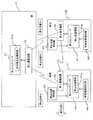
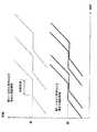
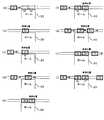
まず、本発明の第1実施形態について説明すると、図1〜図4は本発明の第1実施形態にかかる鉄道車両の運行方法及び運行システムを示すもので、図1はその運行にかかる駅の構成を示す模式的な平面図、図2はその地上側と車両側の運行制御系の構成を示すブロック図、図3はその駅(プラットホーム)への鉄道車両の入出状況の例を(a)〜(i)の順に説明する模式図、図4はその運行ダイヤの例を従来例と比較して示す図である。
【0021】
本実施形態にかかる鉄道システムは、図1に示すように、鉄道路線1に付設される駅2に、鉄道路線1が停止する個所として、複数(図1に示す例では3つ)の車両停止エリアA1〜A3が設けられており、これらの車両停止エリアA1〜A3に同時に複数(ここでは、最大3組)の鉄道車両11a,11b(以下、鉄道車両を個々に区別しない場合には、符号11で示す)が停車できるようになっている。このため、駅2のプラットホーム(以下、単にホームとも言う)20には、車両停止エリアA1〜A3に対応して複数の乗降エリア21〜23が設けられている。
【0022】
各車両停止エリアA1〜A3の相互間には、当然ながら安全距離dが設けられている。この安全距離dは、各車両11の停止誤差(目標停止位置に対する実停止位置との差)の最大値(最大停止誤差)dmaxに基づいて、例えばd=2dmax、或いは、d=2dmax+α(αは安全マージン)と設定される。
なお、本実施形態では、各鉄道車両11は、例えばLRT(Light Rail Transit)等と称される小型で軽量な鉄道車両であって、連結なしの単独車両として運行されるものとする。また、鉄道車両が小型で軽量であってゴー&ストップが容易である特性を生かして、この鉄道路線1は、各駅間距離を比較的短く設定され、全路線距離も比較的短く設定されている。このため、上述のように車両停止エリアA1〜A3が複数設けられているものの、駅、特に、そのプラットホーム20自体も比較的短く設定されている。さらに、各車両11は無人運転で運行されるようになっている。
【0023】
ここで、鉄道車両の運行にかかる装置構成を説明すると、図2に示すように、地上側(例えば駅2)には、地上側制御装置としての地上コンピュータ31と、地上通信装置32とがそなえられており、地上コンピュータ31では、車両停止位置情報31aをはじめとして各種の車両走行情報を算出するようになっており、地上通信装置32を通じて各車両に応じたこれらの情報を発信するようになっている。
【0024】
一方、各車両側には、車上側制御装置としての車上コンピュータ41と、地上通信装置32と通信によって情報を授受する車上通信装置42と、自車両の停止位置を検知する停止位置検知器43と、自車両の速度を検知する車両速度検知器44とがそなえられている。なお、停止位置検知器43は、自車両の停止位置だけでなく走行中の現在位置も検知できるようになっている。
【0025】
車上コンピュータ41では、地上コンピュータ31からの自車両の停止位置情報41aを含む情報を、車上通信装置42を通じて受信して、停止する際には、停止位置検知器43で検知された自車両の位置情報と、車両速度検知器44で検知された自車両の速度情報と、停止位置情報41aとから、自車両の走行を制御するようになっている。
【0026】
また、停止位置検知器43で検知された自車両の位置情報(停止位置情報を含む)や速度情報は、車上コンピュータ41,車上通信装置42,地上通信装置32を通じて地上コンピュータ31に送信されるようになっている。
地上コンピュータ31における車両停止位置情報31aの設定や各車両の安全走行情報の設定に用いられるようになっている。
【0027】
つまり、駅2において、車両が1台も停止していなければ、最も車両進行方向前方側の車両停止エリアA1を現在最も駅2に接近している車両の停止位置に設定する。この場合、2番目に駅2に接近している車両の停止位置は、次に車両進行方向前方側の車両停止エリアA2に設定することになる。
また、図1に示すように、駅2において、1台の車両11aが停止していれば(この車両は、最も車両進行方向側の車両停止エリアA1に停止中)、次に車両進行方向前方側の車両停止エリアA2を現在最も駅2に接近している車両の停止位置に設定する。このように、駅2の車両停止エリアのうち、空いている最も車両進行方向前方側の車両停止エリアを現在最も駅2に接近している車両の停止位置とするようになっている。
【0028】
このようなロジックでは、駅2における車両に到着,発車状況等に応じて、走行中の車両の停止位置は変化することになるが、各車両11は、常に最新の停止位置情報に応じて自車両を停止させるようになっている。
つまり、各車両11では、停止位置情報41aが得られたら、目標とする停止位置の所定距離手前から、自車両の位置情報及び速度情報を参照しながら自車両を減速し目標停止位置に停止させる。この際、停止位置が変更されたら(停止位置変更は、車両進行方向後方側から車両進行方向前方側への変更となる)、例えば、停止位置変更時点で減速を緩めるか又は低速運転に移行し、変更された停止位置の所定距離手前から再び減速し目標停止位置に停止させるようにすればよい。
【0029】
また、地上コンピュータ31では、各車両の走行速度と走行中の位置とを把握しながら、各車両に対する走行速度に応じた移動閉塞距離(先行車両との車間距離)を設定し、移動閉塞距離を確保するような速度制限情報(加速禁止情報や減速情報)を設定して、これを送信し、各車両の安全走行を実施するようになっている。
【0030】
車両の停止時には、通常、停止位置の所定距離手前から所定の減速度で減速し、停止位置でちょうど停止できるように車速を制御するが、前方に先行車が走行している場合には、そのときの自車両の走行速度に応じた移動閉塞距離を確保できるように、適宜速度が抑制される。なお、移動閉塞距離は速度が低くなるほど短くなり、停止時には、上記の安全距離dにほぼ相当した距離となる。
【0031】
さらに、本実施形態では、各車両の車上通信装置42を通じて、各車両間でも通信によって情報を授受できるようになっており、自車両(後続車両)が自車両の直前を走行する車両(先行車両)から位置情報を受信して、地上コンピュータ31からの停止位置情報と先行車両から得られる停止位置情報とを比較して、もしも停止位置情報が異なる場合には、自車両位置に近い方(走行方向後ろ側)の停止位置に自車両を停止させるようにしている。これにより、地上コンピュータ31からの停止位置情報に万一のエラーがあった場合にフェイルセーフ対応できるようになっている。また、地上コンピュータ31からの情報に万一のエラーがあった場合にも、各車両ごとに独自に走行速度に応じた移動閉塞距離(先行車両との車間距離)を設定し、移動閉塞距離を確保するような速度制限(加速禁止や減速)を実施できるようになっている。
【0032】
なお、図示しないが、ホーム20の線路側には、停車した車両11の乗降ドアの開閉と連動して開閉する開閉ドアを備えた仕切り(例えば、フェンス)が設けられており、ホーム20上の乗客が走行中の車両11と接触することのないようにしながら、車両11への乗降をより安全に行なえるようになっている。
【0033】
本発明の第1実施形態にかかる鉄道車両の運行方法及び運行システムは、上述のように構成されているので、例えば、図3に示すように、駅2のホーム20への進入,停止,発進が行なわれる。なお、この例では、車両11は左から右へと進行し、駅2の車両停止エリアは2つ設けられているものとして説明する。また、鉄道車両については、先行車両から順に▲1▼,▲2▼,▲3▼で示す。
【0034】
まず、図3(a)に示すように、ホーム20の車両停止エリアA1,A2の何れにも車両11が停止していない状態で、駅に車両▲1▼が進入してきたら、この車両▲1▼の停止位置は、進行方向前方の車両停止エリアA1に設定される。図3(b)に示すように、車両▲1▼が車両停止エリアA1に停止すると、後続車両▲2▼の停止位置は、空いている車両停止エリアA2に設定される。
【0035】
図3(c)に示すように、車両▲2▼が進入してくる間に、車両▲1▼では乗客の降車が行なわれる。この際、図示しないが、車両▲1▼の乗降ドアとホーム20側の車両停止エリアA1に対応した開閉ドアとが同期して開放される。その後、図3(d)に示すように、車両▲1▼への乗客の乗車が行なわれる一方で、車両▲2▼が車両停止エリアA2に進入し停車する。
【0036】
車両▲1▼への乗客の乗車が終わると、図3(e)に示すように、車両▲1▼の乗降ドアとホーム20側の対応した開閉ドアとが同期して閉鎖される。この一方で、後続車両▲2▼の乗降ドアとホーム20側の車両停止エリアA2に対応した開閉ドアとが同期して開放され、車両▲2▼では乗客の降車が行なわれる。
この後、図3(f)に示すように、車両▲1▼が発進し、車両▲2▼では乗客の乗車が行なわれる。図3(g)に示すように、車両▲2▼における乗客の乗車が完了すると、車両▲2▼の乗降ドアとホーム20側の車両停止エリアA2に対応した開閉ドアとが同期して閉鎖される。
【0037】
その後、図3(h)に示すように、車両▲2▼が発進し、これに続く後続車両▲3▼の停止位置は、空いている最も進行方向前方の車両停止エリアA1に設定される。そして、後続車両▲3▼はこの設定された停止位置である車両停止エリアA1に停止する。
ここでは、車両停止エリアが2つだけ備えられている場合を例に説明したが、3つ以上の車両停止エリアがあれば、各車両11は、常に空いている最も進行方向前方の車両停止エリアを停止位置とすることになる。
【0038】
このようにして、同時に複数の車両(図4では二台)を同一駅に停車させるようにすることで、図4に太線で示すように、車両を同一駅に一台しか停車できない場合(図4中に細線で示す)に比べて、鉄道車両を高頻度(高密度)で運行することができるようになり、輸送効率を向上させることができる。
しかも、本実施形態では、車両は、単独車両で運行されるので、同時に複数の車両を同一駅に停車させるように、車両停止エリアを複数設けても、駅のホーム20の全長は比較的短く構成できる。
【0039】
換言すると、乗客数の多い場合には、車両停止エリアの数分だけの車両数を連結した編成車両に近い輸送力を確保でき、乗客数の少ない場合には、単独車両の利点を生かし、図4中に細線で示すように、車両の運行間隔を空けて、効率よく運行を行なうことができる。
編成車両の場合、乗客キャパシティが大きいため、乗客数の少ない場合に無駄のない運行を行なうためには、車両の運行間隔を大きく空ける必要があり、乗客をホームに長時間待たせることになってしまうが、単独車両の場合には、乗客キャパシティが小さい分だけ、車両の運行間隔をあまり空けなくても無駄のない運行を行なえ、乗客をホームに待たせる時間も少なくなり、運行効率と乗客サービスとを両立させることができる。
【0040】
なお、上述の各車両の運行は、前述のように地上コンピュータ31からの制御信号に基づいて、車上コンピュータ41を通じて行なわれるが、この運行時には、各車両から得られる走行速度と走行中の位置とに基づいて、各車両に対する走行速度に応じた移動閉塞距離(先行車両との車間距離)が設定され、移動閉塞距離を確保するような速度制限情報(加速禁止情報や減速情報)が設定されて、これらの情報に基づいて各車両の走行が制御されるので、走行安全性が確保される。
【0041】
さらに、本実施形態では、各車両は、自車両の直前を走行する車両(先行車両)から位置情報を受信して、地上コンピュータ31からの停止位置情報と先行車両から得られる停止位置情報とを比較して、もしも停止位置情報が異なる場合には、自車両位置に近い方(走行方向後ろ側)の停止位置に自車両を停止させる。これにより、地上コンピュータ31からの停止位置情報に万一のエラーがあった場合にフェイルセーフ対応できる。
【0042】
また、地上コンピュータ31からの情報に万一のエラーがあった場合にも、各車両ごとに独自に走行速度に応じた移動閉塞距離(先行車両との車間距離)を設定し、移動閉塞距離を確保するような速度制限(加速禁止や減速)を実施できるので、走行制御においてもフェイルセーフ対応できる。
また、図3に示す運行方法のように、先行車両の乗降が済んでから後続車両の乗降を行なうように運行すれば、ホーム上の乗客の流れを円滑にさせやすい。
【0043】
[第2実施形態]
次に、本発明の第2実施形態について説明すると、図5は本発明の第2実施形態にかかる鉄道車両の運行方法及び運行システムにおける駅(プラットホーム)への鉄道車両の入出状況の例を(a)〜(i)の順に説明する模式図である。
本実施形態にかかる鉄道システムでは、駅2のプラットホーム20への鉄道車両の入出態様が第1実施形態と異なっているが、駅2側の構成や車両の構成は、第1実施形態(図1,図2)と同様である。そこで、相違点であるプラットホーム20への鉄道車両の入出態様について説明する。
本実施形態では、図5に示すように、駅2のホーム20への進入,停止,発進が行なわれる。なお、この例でも、車両11は左から右へと進行し、駅2の車両停止エリアは2つ設けられているものとして説明する。また、鉄道車両については、先行車両から順に▲1▼,▲2▼,▲3▼,▲4▼で示す。
【0044】
本実施形態では、車両の停止位置が降車用停止位置と乗車用停止位置とで異なっており、駅に進入したら、まず、手前(進行方向後ろ側)の車両停止エリアA2に車両を停止させ乗客の降車を行ない、降車が完了したら前方(進行方向前方側)の車両停止エリアA1に車両を移動させて停止させ乗客の乗車を行なうようになっている。
【0045】
つまり、まず、図5(a)に示すように、ホーム20の車両停止エリアA1,A2の何れにも車両が停止していない状態で、駅に車両▲1▼が進入してきたら、この車両▲1▼の停止位置は、進行方向後ろ側の車両停止エリアA2に設定される。図5(b)に示すように、車両▲1▼が車両停止エリアA2に停止すると、このとき、後続車両▲2▼の停止位置は、車両▲1▼と同様に車両停止エリアA2に設定される。
【0046】
図5(c)に示すように、車両▲2▼が進入してくる間に、車両▲1▼では乗客の降車が行なわれる。この際、図示しないが、車両▲1▼の乗降ドアとホーム20側の車両停止エリアA1に対応した開閉ドアとが同期して開放される。車両▲1▼の降車が完了したら、車両▲1▼の乗降ドアとホーム20側の対応した開閉ドアとが同期して閉鎖される。
【0047】
その後、図5(d)に示すように、車両▲1▼が前方へ移動すると共に、車両▲2▼が駅に進入していき、図5(e)に示すように、車両▲1▼は前方の車両停止エリアA1に停車し、次いで、車両▲2▼が車両停止エリアA2に進入し停車する。ここで、車両▲1▼の乗降ドアとホーム20側の対応した開閉ドアとが同期して開放され、車両▲2▼の乗降ドアとホーム20側の対応した開閉ドアとが同期して開放されて、図5(f)に示すように、車両▲1▼では乗客の乗車が行なわれ、車両▲2▼では乗客の降車が行なわれる。このとき、後続車両▲3▼の停止位置は、車両▲1▼,▲2▼と同様に車両停止エリアA2に設定される。
【0048】
車両▲1▼の乗車が完了し、車両▲2▼の降車が完了すると、車両▲1▼の乗降ドアとホーム20側の対応した開閉ドアとが同期して閉鎖され、車両▲2▼の乗降ドアとホーム20側の対応した開閉ドアとが同期して閉鎖されて、図5(g)に示すように、車両▲1▼は駅を発車し、車両▲2▼は前方へ移動し、車両▲3▼が駅に進入していく。
その後、図5(h)に示すように、車両▲2▼は前方の車両停止エリアA1に停車し、次いで、車両▲3▼が車両停止エリアA2に進入し停車する。ここで、車両▲2▼の乗降ドアとホーム20側の対応した開閉ドアとが同期して開放され、車両▲3▼の乗降ドアとホーム20側の対応した開閉ドアとが同期して開放されて、図5(h)に示すように、車両▲2▼では乗客の乗車が行なわれ、車両▲3▼では乗客の降車が行なわれる。このとき、後続車両▲4▼の停止位置は、車両▲1▼,▲2▼,▲3▼と同様に車両停止エリアA2に設定される。
【0049】
このようにして、停止位置を降車専用と乗車専用とに分離して設定し、進行方向後ろ側の車両停止エリアを降車専用停止位置に、進行方向前方の車両停止エリアを乗車専用停止位置に設定することで、駅のホームへの車両の同時停車を円滑に行なえるようになると共に、駅のホーム等の乗客の流れを円滑にし、乗降をスムースに行なえるようになる。
【0050】
ここでは、車両停止エリアが2つだけ備えられている場合を例に説明したが、例えば、3つの車両停止エリアA1,A2,A3があれば、例えば最も前方の車両停止エリアA1を乗車専用とし、残りの車両停止エリアA2,A3を降車専用として、駅に進入した際には、降車専用の車両停止エリアA2,A3が共に空いていれば前方の車両停止エリアA2を停車位置に設定し、前方の車両停止エリアA2に車両が進入していれば、後方の車両停止エリアA3を停車位置に設定することが考えられる。
【0051】
[第3実施形態]
次に、本発明の第3実施形態について説明すると、図6は本発明の第3実施形態にかかる鉄道車両の運行方法及び運行システムにおける鉄道車両の走行制御を示すフローチャートである。
本実施形態では、駅に停止する際の走行制御を車両側で行なうようにしたもので、特に、地上コンピュータ31からの情報、或いは、先行車両等の位置情報が得られない場合でも、カメラ画像に基づく画像処理などにより自車両から前方の車両の有無を判定できる機能を備えていればこの走行制御を実施できる。なお、駅2の構成は図1に示すものとする。
【0052】
駅2に近づいたら、地上コンピュータ31又は先行車両又は自車両から得た前方の情報から、駅2に進入可能か否かを判定する(ステップS10)。この判定は、駅2の最後尾の車両停止エリアA3が空いているかいないかを判断し、最後尾の車両停止エリアA3が空いておらず、駅2に進入不可能なら、駅の前の指定位置で停車して待機する(ステップS50)。
【0053】
駅2に進入可能なら、まず、最後尾の車両停止エリアA3に停車するものと仮定して、この最後尾の車両停止エリアA3に停車する停車パターンを計算する(ステップS12)。この停車パターンとは、停車位置に至る車両の減速経過に相当する。そして、計算した停車パターンに基づいて停車動作を開始する(ステップS14)。
【0054】
この停車動作中に、一つ先の車両停止エリアA2に車両がいないかを最新の情報から判定し(ステップS20)、車両停止エリアA2に車両がいれば、車両停止エリアA3に停車する停車パターンを続行し(ステップS26)、停止エリアA3に停車する(ステップS40)。一方、車両停止エリアA2に車両がいなければ、車両停止エリアA2に停車する停車パターンを計算する(ステップS22)。そして、計算した停車パターンに基づいて停車動作を開始する(ステップS24)。
【0055】
この停車動作中に、さらに一つ先の最前の車両停止エリアA1に車両がいないかを最新の情報から判定し(ステップS30)、車両停止エリアA1に車両がいれば、車両停止エリアA2に停車する停車パターンを続行し(ステップS36)、停止エリアA2に停車する(ステップS40)。一方、車両停止エリアA1に車両がいなければ、車両停止エリアA1に停車する停車パターンを計算する(ステップS32)。そして、計算した停車パターンに基づいて停車動作を開始して(ステップS34)、停止エリアA1に停車する(ステップS40)。
【0056】
なお、駅に進入不可能な場合には、ステップS50に進んだ場合には、所定周期でステップS10の判定を繰り返すことになる。
このようなロジックで停止を行なうことで、前方の停止エリアの空き状態に応じて、確実に、空いている最前方の停止エリアに安全に車両を停止させることができる。
【0057】
[その他]
以上、本発明の実施形態について説明したが、本発明は上述の実施形態に限定されるものではなく、本発明の趣旨を逸脱しない範囲で種々変形して実施することができる。
例えば、鉄道路線1の全体に付設された駅の車両停止エリアの総数を、この鉄道路線1上を走行させる鉄道車両11の最大数以上に設定すれば、緊急時には、いずれの車両も何れかの駅に停止させることができる。
【0058】
また、本発明は、LRT等の小型で軽量な鉄道車両に限らず適用でき、例えば、APM(Automated People Mover)等と称されている、無人で自動運転されるゴムタイヤ車両方式の車両にも適用しうる。
また、車両編成も単独車両に限らず適用できるが、小型で軽量な鉄道車両により適しており、また、車両編成も単独車両に限らず適用できるが、単独車両をはじめとして、編成車両であっても比較的少ない車両数を連結したものが適している。また、各駅間距離や全路線距離が比較的短いものに限らず適用できるが、各駅間距離を比較的短く設定したものや、全路線距離を比較的短く設定したものにより適している。
【0059】
【発明の効果】
以上詳述したように、本発明の鉄道車両の運行方法および運行システムによれば、駅に複数組みの鉄道車両を同時停車させることで、駅に先行車がいるために後続車が駅前で待機するといった状態を解消することができ、駅前での無駄な待機時間をなくして、鉄道車両を高頻度(高密度)で安全に運行できるようになる。特に、LRT等と称される小型で軽量な鉄道車両を用いて駅間を短く設定し、走行時間に対する駅停車時間が長い鉄道システムに適用すれば、効率よく安全に高密度運行を実施できる。
【0060】
また、該鉄道車両が該駅に進入したら、まず、該鉄道車両を該後方の車両停止エリアに停止させて乗客の降車を行ない、次に、該鉄道車両を該前方の車両停止エリアに進行させて停止させ乗客の乗車を行なうことにより、乗客の降車場所と乗車場所とを分離することで、複数組みの鉄道車両の同時停車を効率よく行なうことができるうえ、乗降をスムースに行なうことができるようになる。
【0061】
該鉄道車両が該駅に進入したら、該複数の車両停止エリアのうちで空いている進行方向最も前方の車両停止エリアに該鉄道車両を停止させて、乗客の降車及び乗車を行なうことにより、シンプルな運行制御で、複数組みの鉄道車両の同時停車を効率よく行なうことができるようになる。
また、上記の複数の車両停止エリアが設けられた駅よりも進行方向前方に通常走行不能車両が発生した場合、該通常走行不能車両の後続車両を上記の複数の車両停止エリアの何れかに退避させることにより、例えば故障等により通常走行不能な車両が発生した時にも後続車両は最寄りの駅に停車できるようになり、後続車両が駅間で立ち往生する事態を回避できる。特に、無人運転を行なう場合に効果的であり、乗客が軌道上を自力で歩く等の退避処置が軽減され、安全な交通システムが可能となる。
【0062】
さらに、該鉄道車両を連結なしの単独車両により構成して運行することにより、乗客が少ない時間帯等に無駄のない運行を行なえる上、必要に応じて、駅に複数の単独車両を同時停車させるようにして、高頻度運行を行なって、輸送量を確保することができる。
地上側に設けられ該鉄道車両の運行を制御するための制御情報を設定して出力する地上側制御装置と、該地上側制御装置及び該鉄道車両の双方に設けられ両者間で通信を行なう路車間通信装置と、該鉄道車両に設けられ該路車間通信装置を通じて該地上側制御装置から送られた該制御情報を受信して該制御信号に基づいて該鉄道車両の運行を制御する車両側制御装置とを備えることにより、地上側制御装置によって統率して運行管理を実施できるようになり、また、鉄道車両の無人運転での運行を行なうことができるようになる。なお、地上側制御装置から送られる制御情報は、車両の発進指令情報や停止指令情報や加減速指令情報等である。
【0063】
また、該鉄道車両には、自車両の位置を検出する位置検出手段が設けられ、該地上側制御装置は、該路車間通信装置を介して該鉄道路線上の上記の各鉄道車両から該位置情報を受信して、該位置情報に基づいて上記の各鉄道車両への制御情報を設定することにより、地上側制御装置から送られる制御情報によって、車両を所定の位置に停止させることができる。
【0064】
さらに、該鉄道車両には、各鉄道車両の相互間で通信を行なう車両間通信装置がそなえられ、該車両側制御装置は、該路車間通信装置を介して該地上側制御装置から送られた該制御情報と、該車両間通信装置を介して該鉄道路線上の他の各鉄道車両から送られた位置情報とに基づいて該鉄道車両の運行を制御することにより、後続車両が先行車両の位置を直接把握でき、地上側制御装置から送られる制御情報に万一何らかのエラーが含まれていても、後続車両が先行車両に必要以上に接近しないように制御することが可能になる。
【0065】
また、該鉄道車両には、自車両の速度を検出する速度検出手段がそなえられ、該車両側制御装置は、受信した自車両前方の鉄道車両(先行車両)の位置情報と、自車両(後続車両)の位置情報及び速度情報とに基づいて該自車両の停止を制御することにより、先行車両が駅に停車している場合、先行車両の車両停止エリアのすぐ後方の車両停止エリアを停止目標に、自車両の速度を制御しながら安全且つ速やかにかかる停止目標の車両停止エリアに自車両を停止させることが可能になる。
【0066】
また、該駅の該車両停止エリアに、該鉄道車両側に設けられた乗降用ドアの開閉と連動するように開閉制御される開閉ドアが設けられていることにより、開閉ドア以外は線路側とプラットホーム等の駅設備側とを仕切るようにしてプラットホーム側の乗客の安全を図ることができる。特に、無人運転を行なう場合に効果的である。
【0067】
また、該鉄道路線に付設された駅の車両停止エリアの総数は、該鉄道路線上を走行させる該鉄道車両の最大数以上に設定されていることにより、緊急時には何れの鉄道車両も何れかの駅に停止することができる。したがって、例えば故障等により通常走行不能な車両が発生した時にも後続車両は最寄りの駅に停車できるようになり、後続車両が駅間で立ち往生する事態を回避でき、特に、無人運転を行なう場合に効果的であり、乗客が軌道上を自力で歩く等の退避処置が軽減され、安全な交通システムが可能となる。
【図面の簡単な説明】
【図1】本発明の第1実施形態にかかる鉄道車両の運行システムにおける駅の構成を示す模式的な平面図である。
【図2】本発明の第1実施形態にかかる鉄道車両の運行システムにおける地上側と車両側の運行制御系の構成を示すブロック図である。
【図3】本発明の第1実施形態にかかる鉄道車両の運行システムにおける駅(プラットホーム)への鉄道車両の入出状況の例を(a)〜(i)の順に説明する模式図である。
【図4】本発明の第1実施形態にかかる鉄道車両の運行システムにおける運行ダイヤの例を従来例と比較して示す図である。
【図5】本発明の第2実施形態にかかる鉄道車両の運行システムにおける駅(プラットホーム)への鉄道車両の入出状況の例を(a)〜(i)の順に説明する模式図である。
【図6】本発明の第3実施形態にかかる鉄道車両の運行システムにおける鉄道車両の走行制御を示すフローチャートである。
【符号の説明】
1 鉄道路線
2 駅
11,11a,11b鉄道車両
20 プラットホーム
21〜23 乗降エリア
31 地上側制御装置としての地上コンピュータ
32 地上通信装置
41 車上側制御装置としての車上コンピュータ
42 車上通信装置
43 停止位置検知器
44 車両速度検知器
A1〜A3 車両停止エリア[0001]
BACKGROUND OF THE INVENTION
The present invention relates to an operation method and an operation system of a new traffic system of track system automatic operation suitable for use in a small and light rail vehicle system such as APM and LRT.
[0002]
[Prior art]
In recent years, for example, a relatively light rail vehicle called LRT (Light Rail Transit) has been developed and studied.
Since such a small and lightweight railway vehicle is easy to go and stop, it is generally set as a relatively short distance between the stations as a single vehicle without connection or as a formation vehicle formed by connecting relatively few vehicles. It is suitable to operate on the route.
[0003]
By the way, although it is not restricted to small and lightweight rail vehicles, such as LRT, generally, in a rail vehicle, it is an important subject to carry out mass transportation of passengers efficiently and safely.
In the case of railroads, it is possible to carry out mass transportation by increasing the number of vehicles connected, but if the number of vehicles connected is set according to the peak number of passengers, the number of useless connections when the number of passengers is small This will cause the vehicle to run and is inefficient. Although it is conceivable to change the number of connected vehicles according to the number of passengers, the work load is large and not realistic. Therefore, generally, the number of connected vehicles is kept constant, and the vehicle is operated at a frequency according to the number of passengers, so that mass transportation can be efficiently performed.
[0004]
However, if the operation frequency of the vehicle is increased according to the number of passengers, the density of vehicles traveling on the route increases, and the preceding vehicle (the preceding vehicle group if the train is connected) and the following vehicle (following vehicle group) Since the distance between the vehicles becomes shorter, the operation of the vehicle must be controlled with high accuracy so as to ensure safety.
Therefore, a technology has been proposed that enables a railway vehicle to operate at a high density while ensuring safety.
[0005]
For example, in
[0006]
More specifically, in the technique disclosed in
[0007]
On the other hand,
[0008]
[Patent Document 1]
JP-A-5-236613
[Non-Patent Document 1]
Japan Society of Invention Disclosure Bulletin, public technical number 98-7654, date of issue 1998.11.2
[Non-Patent Document 2]
Japan Society for Invention and Innovation, Technical Number 98-7655, Issue Date 1998.11.2
[0009]
[Problems to be solved by the invention]
By the way, in the case of a small and light railway vehicle such as an LRT, as described above, it operates as a train that is formed by connecting a single vehicle without connection or a relatively small number of vehicles on a route set between each station relatively short. However, if the distance between stations is short, the stopping time at the station will be relatively long compared to the traveling time between stations, and if the vehicle is operated with high frequency (high density), Since there is a preceding vehicle, the number of cases where the following vehicle is forced to stop before the station increases, and efficient operation cannot be realized.
[0010]
In the case of a car such as a bus (trackless vehicle), the following vehicle can easily overtake the preceding vehicle, but in the case of a railway vehicle (orbital vehicle), basically, if there is a preceding vehicle, the following vehicle stops and waits. I have to. Therefore, in order to operate a railway vehicle as efficiently as possible, that is, at a high density including such a standby time, as disclosed in
[0011]
The present invention has been invented in view of the above-described problems, and provides a railway vehicle operation method and operation system capable of operating a railway vehicle at a higher density while ensuring safety. For the purpose.
[0012]
[Means for Solving the Problems]
In order to achieve such a goal, the railway vehicle operation method of the present invention is a railway vehicle operation method that simultaneously operates a plurality of sets of railway vehicles on a single railway line, and is attached to the railway line. When a plurality of vehicle stop areas are provided in the station so that a plurality of sets of the railway vehicles can be stopped simultaneously, and the railway vehicles are operated at a high frequency, a preceding vehicle is selected from the plurality of vehicle stop areas. Stop in the vehicle stop area ahead in the direction of travel, and then stop the following vehicle in the vehicle stop area behind the travel direction of the plurality of vehicle stop areas, and simultaneously stop a plurality of sets of the rail vehicles at the station It is characterized by letting. In this way, by stopping a plurality of sets of railway vehicles at the station at the same time, it is possible to eliminate the state in which the preceding vehicle is waiting in front of the station because there is a preceding vehicle at the station.
[0013]
Further, when the railway vehicle enters the station, the railway vehicle is first stopped in the rear vehicle stop area to get off the passengers, and then the railway vehicle is advanced to the front vehicle stop area. It is preferable to stop the passenger and board the passenger.
Alternatively, when the railway vehicle enters the station, the railway vehicle can be stopped at the vehicle stopping area that is the frontmost in the traveling direction that is vacant among the plurality of vehicle stopping areas, and passengers can get off and board the vehicle. preferable.
[0014]
Furthermore, it is preferable from the viewpoint of safety that an opening / closing door is provided in the vehicle stop area of the station, and the opening / closing door is controlled so as to be interlocked with the opening / closing of the entrance / exit door provided on the railway vehicle side.
In addition, when a vehicle that cannot normally travel (for example, a faulty vehicle) is generated ahead of the station in which the plurality of vehicle stop areas are provided in the traveling direction, the following vehicle of the vehicle that cannot normally travel is stopped. Although it is preferable to evacuate to any of the areas, conventionally, there are many situations where the vehicle must be stopped between stations (particularly in front of the station), and passengers may be trapped in the vehicle.
[0015]
Furthermore, it is preferable that the railway vehicle is operated by being constituted by a single vehicle without connection.
A railway vehicle operating system of the present invention is a railway vehicle operating system that simultaneously operates a plurality of sets of railway vehicles on a single railway line, and a plurality of sets of the railways are installed at a station attached to the railway line. A plurality of vehicle stop areas are provided so that the vehicles can stop simultaneously, and a plurality of sets of the railway vehicles can be stopped at the station. In this way, by stopping a plurality of sets of railway vehicles at the station at the same time, it is possible to eliminate the state in which the preceding vehicle is waiting in front of the station because there is a preceding vehicle at the station.
[0016]
Furthermore, a ground side control device that is provided on the ground side and sets and outputs control information for controlling the operation of the railway vehicle, and is provided in both the ground side control device and the rail vehicle, and communicates between the two. A road-to-vehicle communication device to be performed, and a vehicle that is provided in the railway vehicle, receives the control information sent from the ground side control device through the road-to-vehicle communication device, and controls the operation of the rail vehicle based on the control signal And a side control device.
[0017]
Further, the railway vehicle is provided with position detecting means for detecting the position of the own vehicle, and the ground side control device receives the position from each rail vehicle on the railway line via the road-to-vehicle communication device. It is preferable to receive the information and set the control information for each railway vehicle based on the position information.
Each of the above-mentioned railway vehicles is provided with an inter-vehicle communication device that performs communication between the respective rail vehicles, and the vehicle-side control device is sent from the ground-side control device via the road-to-vehicle communication device. It is preferable to control the operation of the railway vehicle based on the control information and position information sent from each other railway vehicle on the railway line via the inter-vehicle communication device.
[0018]
Further, the railway vehicle is provided with speed detecting means for detecting the speed of the own vehicle, and the vehicle side control device receives the received position information of the railway vehicle (preceding vehicle) ahead of the own vehicle and the own vehicle (following vehicle). It is preferable to control the stop of the host vehicle based on the position information and speed information of the vehicle.
In addition, it is preferable that an opening / closing door that is controlled to be opened / closed is provided in the vehicle stop area of the station so as to be interlocked with the opening / closing of the door for getting on / off the railway vehicle.
[0019]
Moreover, it is preferable that the total number of the vehicle stop areas of the station attached to the railway line is set to be equal to or greater than the maximum number of the railway vehicles traveling on the railway line.
Furthermore, it is preferable that the railway vehicle is constituted by a single vehicle without connection.
[0020]
DETAILED DESCRIPTION OF THE INVENTION
Hereinafter, embodiments of the present invention will be described with reference to the drawings.
[First Embodiment]
First, the first embodiment of the present invention will be described. FIGS. 1 to 4 show an operation method and an operation system of a railway vehicle according to the first embodiment of the present invention, and FIG. FIG. 2 is a block diagram showing the configuration of the ground-side and vehicle-side operation control systems, and FIG. 3 is an example of an entry / exit state of a railway vehicle at the station (platform). The schematic diagram demonstrated in order of-(i), FIG. 4 is a figure which shows the example of the operation | movement diagram compared with a prior art example.
[0021]
As shown in FIG. 1, the railway system according to this embodiment has a plurality of (three in the example shown in FIG. 1) vehicle stops as stations where the
[0022]
Of course, a safety distance d is provided between the vehicle stop areas A1 to A3. This safe distance d is, for example, d = 2dmax, or d = 2dmax + α (α is based on the maximum value (maximum stop error) dmax of the stop error (difference between the actual stop position and the target stop position) of each
In the present embodiment, each
[0023]
Here, the apparatus configuration relating to the operation of the railway vehicle will be described. As shown in FIG. 2, the ground side (for example, the station 2) is provided with a
[0024]
On the other hand, on each vehicle side, an
[0025]
The on-
[0026]
The position information (including stop position information) and speed information of the host vehicle detected by the
It is used for setting the vehicle
[0027]
That is, if no vehicle is stopped at the
Further, as shown in FIG. 1, if one vehicle 11a is stopped at the station 2 (this vehicle is stopped in the vehicle stop area A1 closest to the vehicle traveling direction), then the vehicle traveling direction forward The vehicle stop area A2 on the side is set to the stop position of the vehicle that is currently closest to the
[0028]
In such a logic, the stop position of the running vehicle changes depending on the arrival and departure conditions of the vehicle at the
That is, in each
[0029]
Further, the
[0030]
When the vehicle stops, the vehicle speed is usually controlled so that the vehicle decelerates at a predetermined deceleration from a predetermined distance before the stop position and can be stopped just at the stop position.car When the vehicle is traveling, the speed is appropriately suppressed so as to ensure the movement blockage distance according to the traveling speed of the host vehicle at that time. The moving blockage distance becomes shorter as the speed becomes lower, and becomes a distance substantially corresponding to the safety distance d when stopped.
[0031]
Further, in the present embodiment, information can be exchanged between the vehicles through the on-
[0032]
Although not shown, a partition (for example, a fence) having an opening / closing door that opens and closes in conjunction with opening / closing of the entrance / exit door of the stopped
[0033]
Since the railway vehicle operating method and system according to the first embodiment of the present invention are configured as described above, for example, as shown in FIG. Is done. In this example, it is assumed that the
[0034]
First, as shown in FIG. 3A, when the vehicle {circle around (1)} enters the station with the
[0035]
As shown in FIG. 3C, while the vehicle {circle around (2)} enters, passengers get off at the vehicle {circle around (1)}. At this time, although not shown, the entry / exit door of the vehicle (1) and the opening / closing door corresponding to the vehicle stop area A1 on the
[0036]
When passengers get on the vehicle {circle around (1)}, as shown in FIG. 3 (e), the entry / exit door of the vehicle {circle around (1)} and the corresponding open / close door on the
Thereafter, as shown in FIG. 3 (f), the vehicle {circle around (1)} starts, and passengers get on the vehicle {circle around (2)}. As shown in FIG. 3 (g), when passenger boarding in the vehicle {circle around (2)} is completed, the entry / exit door of the vehicle {circle around (2)} and the open / close door corresponding to the vehicle stop area A2 on the
[0037]
Thereafter, as shown in FIG. 3 (h), the vehicle {circle around (2)} starts, and the subsequent stop position of the following vehicle {circle around (3)} is set to the vacant front vehicle stop area A1. Then, the succeeding vehicle (3) stops in the vehicle stop area A1, which is the set stop position.
Here, the case where only two vehicle stop areas are provided has been described as an example, but if there are three or more vehicle stop areas, each
[0038]
In this way, when a plurality of vehicles (two in FIG. 4) are stopped at the same station at the same time, only one vehicle can be stopped at the same station as shown by a thick line in FIG. Compared to (indicated by a thin line in FIG. 4), the railway vehicle can be operated with high frequency (high density), and the transportation efficiency can be improved.
Moreover, in this embodiment, since the vehicle is operated by a single vehicle, even if a plurality of vehicle stop areas are provided so that a plurality of vehicles stop at the same station at the same time, the total length of the
[0039]
In other words, when the number of passengers is large, it is possible to secure a transport capacity close to that of a knitted vehicle in which the number of vehicles corresponding to the number of vehicle stop areas is connected. As shown by the thin line in 4, the operation interval can be increased and the operation can be efficiently performed.
In the case of organized vehicles, the passenger capacity is large, so in order to operate without waste when the number of passengers is small, it is necessary to make the operation intervals of the vehicles large, and the passengers must wait for a long time at the home. However, in the case of a single vehicle, since the passenger capacity is small, it is possible to operate without waste even if the operation interval of the vehicle is not so much, and the time for the passenger to wait at the home is reduced, and the operation efficiency is reduced. The passenger service can be compatible.
[0040]
The operation of each vehicle described above is performed through the on-
[0041]
Furthermore, in this embodiment, each vehicle receives position information from a vehicle (preceding vehicle) that runs immediately before the host vehicle, and receives stop position information from the
[0042]
In addition, even if there is an error in the information from the
In addition, as in the operation method shown in FIG. 3, if the operation is performed so that the subsequent vehicle gets on and off after the preceding vehicle gets on and off, the flow of passengers on the platform can be made smooth.
[0043]
[Second Embodiment]
Next, the second embodiment of the present invention will be described. FIG. 5 shows an example of the state of entry / exit of a railway vehicle to / from a station (platform) in the railway vehicle operation method and operation system according to the second embodiment of the present invention ( It is a schematic diagram demonstrated in order of a)-(i).
In the railway system according to the present embodiment, the manner of entering and exiting the railway vehicle to and from the
In the present embodiment, as shown in FIG. 5, entry, stop, and start of the
[0044]
In this embodiment, the stop position of the vehicle is different between the stop position for getting off and the stop position for getting on the board. When entering the station, the vehicle is first stopped in the vehicle stop area A2 in front (rear side in the traveling direction) and the passenger is stopped. When the disembarkation is completed, the vehicle is moved to the vehicle stop area A1 ahead (the front side in the traveling direction) and stopped to allow passengers to get on.
[0045]
That is, first, as shown in FIG. 5A, when the vehicle {circle around (1)} enters the station with the vehicle not stopped in any of the vehicle stop areas A1, A2 of the
[0046]
As shown in FIG. 5C, while the vehicle {circle around (2)} enters, passengers get off at the vehicle {circle around (1)}. At this time, although not shown, the entry / exit door of the vehicle (1) and the opening / closing door corresponding to the vehicle stop area A1 on the
[0047]
Thereafter, as shown in FIG. 5 (d), the vehicle {circle around (1)} moves forward and the vehicle {circle around (2)} enters the station. As shown in FIG. 5 (e), the vehicle {circle around (1)} The vehicle stops in the front vehicle stop area A1, and then the vehicle {circle around (2)} enters the vehicle stop area A2 and stops. Here, the entry / exit door of the vehicle {circle around (1)} and the corresponding opening / closing door on the
[0048]
When the boarding of the vehicle (1) is completed and the boarding of the vehicle (2) is completed, the boarding door of the vehicle (1) and the corresponding opening / closing door on the
Thereafter, as shown in FIG. 5 (h), the vehicle {circle around (2)} stops in the front vehicle stop area A1, and then the vehicle {circle around (3)} enters the vehicle stop area A2 and stops. Here, the entry / exit door of the vehicle (2) and the corresponding opening / closing door on the
[0049]
In this way, the stop position is set separately for exclusive use for getting off and for exclusive use for getting off, the vehicle stop area at the rear in the direction of travel is set as the stop position for exclusive use of the get off, and the vehicle stop area in the front of the direction of travel is set as the stop position for exclusive use By doing so, it becomes possible to smoothly stop the vehicle simultaneously on the platform of the station, smooth the flow of passengers such as the platform of the station, and smoothly get on and off.
[0050]
Here, the case where only two vehicle stop areas are provided has been described as an example. However, for example, if there are three vehicle stop areas A1, A2, and A3, for example, the frontmost vehicle stop area A1 is dedicated for boarding. When entering the station with the remaining vehicle stop areas A2 and A3 dedicated to getting off, if both of the vehicle stop areas A2 and A3 dedicated to getting off are vacant, the front vehicle stop area A2 is set as the stop position, If the vehicle has entered the front vehicle stop area A2, the rear vehicle stop area A3 may be set as the stop position.
[0051]
[Third Embodiment]
Next, a third embodiment of the present invention will be described. FIG. 6 is a flowchart showing a railway vehicle traveling control in the railway vehicle operating method and system according to the third embodiment of the present invention.
In the present embodiment, traveling control when stopping at a station is performed on the vehicle side, and in particular, even when information from the
[0052]
When approaching the
[0053]
If it is possible to enter the
[0054]
During this stopping operation, it is determined from the latest information whether there is a vehicle in the preceding vehicle stop area A2 (step S20), and if there is a vehicle in the vehicle stop area A2, a stop pattern for stopping in the vehicle stop area A3 (Step S26) and stop at the stop area A3 (step S40). On the other hand, if there is no vehicle in the vehicle stop area A2, a stop pattern for stopping in the vehicle stop area A2 is calculated (step S22). Then, a stop operation is started based on the calculated stop pattern (step S24).
[0055]
During this stopping operation, it is determined from the latest information whether there is a vehicle in the foremost vehicle stop area A1 (step S30). If there is a vehicle in the vehicle stop area A1, the vehicle stops in the vehicle stop area A2. The stopping pattern to be continued is continued (step S36), and the vehicle stops in the stop area A2 (step S40). On the other hand, if there is no vehicle in the vehicle stop area A1, a stop pattern for stopping in the vehicle stop area A1 is calculated (step S32). Then, a stop operation is started based on the calculated stop pattern (step S34), and the vehicle stops in the stop area A1 (step S40).
[0056]
When it is impossible to enter the station, when the process proceeds to step S50, the determination in step S10 is repeated at a predetermined cycle.
By stopping with such logic, the vehicle can be safely stopped in the vacant forward stop area according to the empty state of the forward stop area.
[0057]
[Others]
Although the embodiments of the present invention have been described above, the present invention is not limited to the above-described embodiments, and various modifications can be made without departing from the spirit of the present invention.
For example, if the total number of vehicle stop areas of stations attached to the
[0058]
Further, the present invention can be applied not only to a small and light rail vehicle such as an LRT, but also applied to a rubber tire vehicle type vehicle which is called an APM (Automated People Mover) or the like and is automatically driven by an unmanned vehicle. Yes.
In addition, the vehicle formation can be applied not only to a single vehicle, but is more suitable for a small and light railway vehicle, and the vehicle formation can also be applied to a single vehicle. However, it is suitable to connect a relatively small number of vehicles. Further, the present invention can be applied not only to those having a relatively short distance between stations or the total distance between stations, but is more suitable for a distance between the stations being set to be relatively short or a distance being set to be relatively short.
[0059]
【The invention's effect】
As described above in detail, according to the railway vehicle operation method and operation system of the present invention, by simultaneously stopping a plurality of sets of railway vehicles at the station, the preceding vehicle is waiting in front of the station because there is a preceding vehicle at the station. It is possible to eliminate such a situation, and it is possible to safely operate a railway vehicle with high frequency (high density) by eliminating useless waiting time in front of the station. In particular, if a small and light railway vehicle called LRT or the like is used to set a short distance between stations and the system is applied to a railway system with a long station stop time with respect to traveling time, high-density operation can be carried out efficiently and safely.
[0060]
Further, when the railway vehicle enters the station, the railway vehicle is first stopped in the rear vehicle stop area to get off the passengers, and then the railway vehicle is advanced to the front vehicle stop area. Passengers by stopping and boarding passengersFall of By separating the vehicle location and the boarding location, it is possible to efficiently stop a plurality of sets of railway vehicles at the same time, and to get on and off smoothly.
[0061]
When the railway vehicle enters the station, the railway vehicle is stopped at the vehicle stopping area that is the frontmost in the traveling direction that is vacant among the plurality of vehicle stopping areas, and passengers get off and board the vehicle. With efficient operation control, multiple sets of railway vehicles can be efficiently stopped simultaneously.
In addition, when a vehicle that cannot normally travel is generated ahead of the station in which the plurality of vehicle stop areas are provided in the traveling direction, a vehicle that follows the vehicle that cannot normally travel is retracted to one of the plurality of vehicle stop areas. By doing so, for example, when a vehicle that cannot normally travel due to a failure or the like occurs, the subsequent vehicle can stop at the nearest station, and a situation in which the subsequent vehicle gets stuck between the stations can be avoided. In particular, it is effective when unmanned driving is performed, and evacuation measures such as a passenger walking on a track by himself / herself are reduced, and a safe traffic system is possible.
[0062]
Furthermore, by operating the railway vehicle with a single vehicle without connection, it is possible to operate without waste in a time zone where there are few passengers, and if necessary, a plurality of single vehicles can be stopped simultaneously at the station. By doing so, it is possible to ensure high transportation volume and secure transportation.
A ground-side control device that is provided on the ground side and sets and outputs control information for controlling the operation of the railway vehicle, and a path that is provided in both the ground-side control device and the rail vehicle and performs communication between the two. An inter-vehicle communication device and a vehicle-side control that is provided in the railway vehicle and receives the control information sent from the ground-side control device through the road-to-vehicle communication device and controls the operation of the rail vehicle based on the control signal By providing the device, it becomes possible to carry out operation management under the control of the ground side control device, and it is possible to operate the railcar in unmanned operation. The control information sent from the ground side control device is vehicle start command information, stop command information, acceleration / deceleration command information, and the like.
[0063]
Further, the railway vehicle is provided with position detecting means for detecting the position of the own vehicle, and the ground side control device receives the position from each rail vehicle on the railway line via the road-to-vehicle communication device. By receiving the information and setting the control information for each railway vehicle based on the position information, the vehicle can be stopped at a predetermined position by the control information sent from the ground side control device.
[0064]
Further, the railway vehicle is provided with an inter-vehicle communication device that performs communication between the respective rail vehicles, and the vehicle-side control device is sent from the ground-side control device via the road-to-vehicle communication device. By controlling the operation of the railway vehicle based on the control information and the position information sent from each other railway vehicle on the railway line via the inter-vehicle communication device, the succeeding vehicle can The position can be directly grasped, and even if an error is included in the control information sent from the ground side control device, it is possible to control the following vehicle so as not to approach the preceding vehicle more than necessary.
[0065]
Further, the railway vehicle is provided with speed detecting means for detecting the speed of the own vehicle, and the vehicle side control device receives the received position information of the railway vehicle (preceding vehicle) ahead of the own vehicle and the own vehicle (following vehicle). If the preceding vehicle is stopped at the station by controlling the stop of the host vehicle based on the position information and the speed information of the vehicle), the vehicle stop area immediately behind the vehicle stop area of the preceding vehicle is set as the stop target. In addition, the host vehicle can be stopped safely and promptly in the stop target vehicle stop area while controlling the speed of the host vehicle.
[0066]
In addition, the vehicle stop area of the station is provided with an opening / closing door that is controlled to be opened / closed in conjunction with the opening / closing of the entrance / exit door provided on the railway vehicle side. The passengers on the platform side can be secured by separating the station equipment side such as the platform. This is particularly effective when performing unattended operation.
[0067]
In addition, the total number of vehicle stop areas of stations attached to the railway line is set to be equal to or greater than the maximum number of railway vehicles that travel on the railway line, so that any railway vehicle is You can stop at the station. Therefore, for example, when a vehicle that cannot normally travel due to a failure or the like occurs, the following vehicle can stop at the nearest station, and the situation where the following vehicle gets stuck between the stations can be avoided, especially when unmanned operation is performed. This is effective, and a evacuation procedure such as a passenger walking on a track by himself / herself is reduced, and a safe transportation system is possible.
[Brief description of the drawings]
FIG. 1 is a schematic plan view showing a configuration of a station in a railway vehicle operation system according to a first embodiment of the present invention.
FIG. 2 is a block diagram showing the configuration of the ground-side and vehicle-side operation control systems in the railway vehicle operation system according to the first embodiment of the present invention.
FIG. 3 is a schematic diagram for explaining an example of the status of entry / exit of a railway vehicle to / from a station (platform) in the railway vehicle operation system according to the first embodiment of the present invention.
FIG. 4 is a diagram showing an example of an operation schedule in the railway vehicle operation system according to the first embodiment of the present invention in comparison with a conventional example.
FIG. 5 is a schematic diagram for explaining an example of the status of entering and exiting a railway vehicle from / to a station (platform) in the railway vehicle operation system according to the second embodiment of the present invention in the order of (a) to (i).
FIG. 6 is a flowchart showing travel control of a railway vehicle in a railway vehicle operation system according to a third embodiment of the present invention.
[Explanation of symbols]
1 Railway lines
2 stations
11, 11a, 11b railway vehicles
20 platform
21-23 Boarding area
31 Ground computer as ground side control device
32 Terrestrial communication equipment
41 Onboard computer as a vehicle upper side control device
42 On-vehicle communication device
43 Stop position detector
44 Vehicle speed detector
A1-A3 Vehicle stop area
Claims (4)
Translated fromJapanese該鉄道路線に付設された駅に、複数組みの該鉄道車両が同時に停止しうるように複数の車両停止エリアを設け、
該鉄道車両を高頻度で運行する場合には、先行車両を該複数の車両停止エリアのうち進行方向前方の車両停止エリアに停止させ、ついで、後続車両を該複数の車両停止エリアのうち進行方向後方の車両停止エリアに停止させるようにして、該駅に複数組みの該鉄道車両を同時停車させるとともに、
該鉄道車両が該駅に進入したら、該複数の車両停止エリアのうちで空いている進行方向最も前方の車両停止エリアに該鉄道車両を停止させて、乗客の降車及び乗車を行なう
ことを特徴とする、鉄道車両の運行方法。A railway vehicle operation method for simultaneously operating a plurality of sets of railway vehicles on a single railway line,
In the station attached to the railway line, a plurality of vehicle stop areas are provided so that a plurality of sets of the railway vehicles can be stopped simultaneously,
When the railway vehicle is operated at a high frequency, the preceding vehicle is stopped in the vehicle stop area ahead of the traveling direction in the plurality of vehicle stop areas, and then the subsequent vehicle is moved in the traveling direction in the plurality of vehicle stop areas. While stopping at the rear vehicle stop area, simultaneously stopping a plurality of sets of the railway vehicles at the station,
When the railway vehicle enters the station, the railway vehicle is stopped at the vehicle stopping area that is the frontmost in the traveling direction that is vacant among the plurality of vehicle stopping areas, and passengers get off and board the vehicle. How to operate a rail car.
ことを特徴とする、請求項1記載の鉄道車両の運行方法。2. The railway vehicle according to claim 1, wherein an opening / closing door is provided in the vehicle stop area of the station, and the opening / closing door is controlled so as to be interlocked with opening / closing of the entrance / exit door provided on the railway vehicle side. Navigation method.
ことを特徴とする、請求項1又は2記載の鉄道車両の運行方法。When a vehicle that cannot normally travel is ahead of the station in which the plurality of vehicle stop areas are provided in the traveling direction, a vehicle following the vehicle that cannot normally travel is retracted to one of the plurality of vehicle stop areas. The method for operating a railway vehicle according to claim 1 or 2, characterized in that:
ことを特徴とする、請求項1〜3のいずれか1項に記載の鉄道車両の運行方法。Characterized by operation constituted by a single vehicle without connecting the iron road vehicle, travelinghow a railway vehicle according to any one of claims 1 to3.
Priority Applications (1)
| Application Number | Priority Date | Filing Date | Title |
|---|---|---|---|
| JP2003159443AJP4436073B2 (en) | 2003-06-04 | 2003-06-04 | Railway vehicle operation method and operation system |
Applications Claiming Priority (1)
| Application Number | Priority Date | Filing Date | Title |
|---|---|---|---|
| JP2003159443AJP4436073B2 (en) | 2003-06-04 | 2003-06-04 | Railway vehicle operation method and operation system |
Publications (2)
| Publication Number | Publication Date |
|---|---|
| JP2004359089A JP2004359089A (en) | 2004-12-24 |
| JP4436073B2true JP4436073B2 (en) | 2010-03-24 |
Family
ID=34052500
Family Applications (1)
| Application Number | Title | Priority Date | Filing Date |
|---|---|---|---|
| JP2003159443AExpired - LifetimeJP4436073B2 (en) | 2003-06-04 | 2003-06-04 | Railway vehicle operation method and operation system |
Country Status (1)
| Country | Link |
|---|---|
| JP (1) | JP4436073B2 (en) |
Cited By (1)
| Publication number | Priority date | Publication date | Assignee | Title |
|---|---|---|---|---|
| CN102089180B (en)* | 2008-07-11 | 2013-03-13 | 三菱电机株式会社 | Train control system |
Families Citing this family (5)
| Publication number | Priority date | Publication date | Assignee | Title |
|---|---|---|---|---|
| JP5137483B2 (en)* | 2007-07-11 | 2013-02-06 | 三菱電機株式会社 | Train operation management system |
| EP3121092B1 (en)* | 2015-07-21 | 2019-02-27 | Siemens Mobility GmbH | System and method for rail vehicle evacuation |
| FR3059948A1 (en)* | 2016-12-08 | 2018-06-15 | Alstom Transport Technologies | METHOD FOR CONTROLLING A RAILWAY VEHICLE, CONTROL SYSTEM AND RAILWAY VEHICLE THEREFOR |
| CN112693504B (en)* | 2021-03-25 | 2021-06-22 | 北京全路通信信号研究设计院集团有限公司 | Multi-train control system and method based on train-to-train communication |
| CN115140122B (en)* | 2022-06-29 | 2023-11-17 | 北京全路通信信号研究设计院集团有限公司 | Method and system for combining group trains with inter-field connection |
Family Cites Families (5)
| Publication number | Priority date | Publication date | Assignee | Title |
|---|---|---|---|---|
| JPH05236613A (en)* | 1992-02-19 | 1993-09-10 | Hitachi Ltd | Operating method for rolling stock |
| JP3607966B2 (en)* | 1997-11-04 | 2005-01-05 | トヨタ自動車株式会社 | Driving support system |
| JP2000264210A (en)* | 1999-03-12 | 2000-09-26 | Toshiba Corp | Vehicle traffic system |
| US6220171B1 (en)* | 1999-04-06 | 2001-04-24 | Universal City Studios | Amusement ride |
| JP2001030900A (en)* | 1999-07-26 | 2001-02-06 | Nippon Signal Co Ltd:The | Ato ground device |
- 2003
- 2003-06-04JPJP2003159443Apatent/JP4436073B2/ennot_activeExpired - Lifetime
Cited By (1)
| Publication number | Priority date | Publication date | Assignee | Title |
|---|---|---|---|---|
| CN102089180B (en)* | 2008-07-11 | 2013-03-13 | 三菱电机株式会社 | Train control system |
Also Published As
| Publication number | Publication date |
|---|---|
| JP2004359089A (en) | 2004-12-24 |
Similar Documents
| Publication | Publication Date | Title |
|---|---|---|
| CN108263449B (en) | Urban rail train tracking method based on speed tracking | |
| CN107878513B (en) | Rescue method for unpositioning of unmanned train | |
| KR101463250B1 (en) | How to drive a vehicle in an auto-driving vehicle system | |
| CN112406963A (en) | Train operation safety protection system without secondary train occupation detection equipment | |
| KR20090122847A (en) | Joining Control Method and Joining Control System for Automatic Vehicles | |
| WO2011086629A1 (en) | Operation support device and automatic operation device | |
| CN109353249A (en) | A kind of ATP automatic passing over of neutral section area processing method | |
| JP7289184B2 (en) | Automatic train operation system | |
| CN101279604A (en) | Mini suspension type magneto-dynamic unpiloted vehicle and track therefor | |
| CN113650658A (en) | A Tramway Control System at Level Crossing | |
| JP3364901B2 (en) | How to use the runway | |
| JP4436073B2 (en) | Railway vehicle operation method and operation system | |
| CN107571890B (en) | Intelligent rail transit system | |
| CN108986449A (en) | It is a kind of based on the fast public traffic system that do not stop for getting rid of extension automatically | |
| CN108163008A (en) | A kind of rail system and its control method of public dynamic means of transportation | |
| CN112907116B (en) | Method and system for scheduling multiple trackless vehicles of amusement item | |
| JP3607966B2 (en) | Driving support system | |
| CN118025267A (en) | Regulation and control method for preventing rear-end collision of front running train of braking failure train | |
| CN114394128B (en) | Train control method and system, vehicle-mounted subsystem and trackside resource management subsystem | |
| JP3664037B2 (en) | Vehicle traffic system and vehicle travel control device | |
| JP2000264209A (en) | Vehicle traffic system | |
| JP2001229491A (en) | Automatic avoidance device for emergency vehicles | |
| CN109552353B (en) | Rail transit tool non-stop passenger getting-on and getting-off device | |
| JP2000264207A (en) | Vehicle traffic system | |
| CN110466623A (en) | A kind of formula on-board and off-board public transit system that do not stop |
Legal Events
| Date | Code | Title | Description |
|---|---|---|---|
| A621 | Written request for application examination | Free format text:JAPANESE INTERMEDIATE CODE: A621 Effective date:20060524 | |
| A131 | Notification of reasons for refusal | Free format text:JAPANESE INTERMEDIATE CODE: A131 Effective date:20081007 | |
| A131 | Notification of reasons for refusal | Free format text:JAPANESE INTERMEDIATE CODE: A131 Effective date:20090414 | |
| A521 | Request for written amendment filed | Free format text:JAPANESE INTERMEDIATE CODE: A523 Effective date:20090612 | |
| A131 | Notification of reasons for refusal | Free format text:JAPANESE INTERMEDIATE CODE: A131 Effective date:20090901 | |
| A521 | Request for written amendment filed | Free format text:JAPANESE INTERMEDIATE CODE: A523 Effective date:20091026 | |
| TRDD | Decision of grant or rejection written | ||
| A01 | Written decision to grant a patent or to grant a registration (utility model) | Free format text:JAPANESE INTERMEDIATE CODE: A01 Effective date:20091201 | |
| A01 | Written decision to grant a patent or to grant a registration (utility model) | Free format text:JAPANESE INTERMEDIATE CODE: A01 | |
| A61 | First payment of annual fees (during grant procedure) | Free format text:JAPANESE INTERMEDIATE CODE: A61 Effective date:20091225 | |
| R151 | Written notification of patent or utility model registration | Ref document number:4436073 Country of ref document:JP Free format text:JAPANESE INTERMEDIATE CODE: R151 | |
| FPAY | Renewal fee payment (event date is renewal date of database) | Free format text:PAYMENT UNTIL: 20130108 Year of fee payment:3 | |
| FPAY | Renewal fee payment (event date is renewal date of database) | Free format text:PAYMENT UNTIL: 20140108 Year of fee payment:4 | |
| S111 | Request for change of ownership or part of ownership | Free format text:JAPANESE INTERMEDIATE CODE: R313111 | |
| R350 | Written notification of registration of transfer | Free format text:JAPANESE INTERMEDIATE CODE: R350 | |
| EXPY | Cancellation because of completion of term |