JP4435583B2 - Simple toilet - Google Patents
Simple toiletDownload PDFInfo
- Publication number
- JP4435583B2 JP4435583B2JP2004009991AJP2004009991AJP4435583B2JP 4435583 B2JP4435583 B2JP 4435583B2JP 2004009991 AJP2004009991 AJP 2004009991AJP 2004009991 AJP2004009991 AJP 2004009991AJP 4435583 B2JP4435583 B2JP 4435583B2
- Authority
- JP
- Japan
- Prior art keywords
- armrest
- guide groove
- fixed
- movable
- toilet
- Prior art date
- Legal status (The legal status is an assumption and is not a legal conclusion. Google has not performed a legal analysis and makes no representation as to the accuracy of the status listed.)
- Expired - Fee Related
Links
Images


Landscapes
- Non-Flushing Toilets (AREA)
- Toilet Supplies (AREA)
- Accommodation For Nursing Or Treatment Tables (AREA)
Description
Translated fromJapanese本発明は持運びが出来る簡易便器に関するものである。 The present invention relates to a portable toilet that can be carried.
〔従来の技術〕
この種の簡易便器は一般に室内所定個所に置かれ、病人、老人、身障者が使用する場合が多い。したがって上記体の不自由な人が使用する場合、使い勝手の良い構造を採用することが必要とされる。
特に排便時に使用者が排便容易な姿勢をとり得るようにすることが望ましい。排便容易な姿勢とは便器本体に腰かけた使用者が前かがみになる姿勢である。
このような前かがみになる姿勢をとり易くするために、従来便器本体の前側に腕置台を配置した構成(特許文献1)、あるいは便器本体上面両側に立設した肘掛けの先端部に握持杆を回動可能に取付けた構成(特許文献2)等が提供されている。[Conventional technology]
This type of toilet is generally placed at a predetermined place in the room and is often used by sick people, elderly people, and disabled people. Therefore, it is necessary to adopt a user-friendly structure when used by a person with a physical disability.
In particular, it is desirable that the user can take a posture that facilitates defecation during defecation. Defecation and easy attitude is the attitude of the user who sat down on the toilet bodyis leaning forward.
In order to make it easy to take such a leaning posture, a gripping rod is conventionally attached to the front end portion of the toilet body (Patent Document 1) or the armrests standing on both sides of the upper surface of the toilet body. The structure (patent document 2) etc. which were attached so that rotation was possible are provided.
上記従来構成のうち、便器本体の前側に腕置台を配置した構成では、腕置台や該腕置台を支持するための支持台等の部材が別個に必要であり、また場所をとるし、使用者が便器本体に腰かけたり立上ったりする時にも腕置台や支持台等が干渉する。
また肘掛けの先端部に握持杆を回動可能に取付けた構成では、肘掛けと云う部材が別個に必要であるし、前かがみの姿勢では肘掛けと握持杆とが使用者の体にフィットしにくゝ使い勝手が悪い。Among the above-described conventional configurations, in the configuration in which the arm rest is arranged on the front side of the toilet body, a member such as an arm rest and a support base for supporting the arm rest are separately required, and the space is increased. Even when sitting on the toilet body or standing up, the arm rest and support stand interfere.
In addition, in the configuration where the gripping rod is pivotally attached to the tip of the armrest, a member called an armrest is required separately, and in the leaning posture, the armrest and the gripping rod fit the user's body. It is not easy to use.
本発明は上記従来の課題を解決するための手段として、便器本体(2) 上面両側から肘掛け(4) を立設した便器であって、該肘掛け(4) は支枠(9) と、該支枠(9) に支持されている肘掛け台(8) とからなり、両方または一方の肘掛け(4) の該肘掛け台(8) は固定肘掛け台(81)と、該固定肘掛け台(81)上に前後に摺動可能に配置されている可動肘掛け台(82)と、該固定肘掛け台(81)の根端部上面に固設され、該可動肘掛け台(82)の上面レベルを略等しくする固定板(82A) と、からなり、該固定肘掛け台(81)の上面には長手方向に直線状ガイド溝(83)が形成されており、該直線状ガイド溝(83)の前端部には外側に分岐する円弧状ガイド溝(84)が連通されており、一方該可動肘掛け台(82)の下面からは該ガイド溝(83,84) に摺動可能に嵌合するガイドピン(85,86) が前後一対突設されており、該可動肘掛け台(82)が該固定肘掛け台(81)を摺動して摺動前端に達した時、該可動肘掛け台(82)を内側に回動せしめれば該後側ガイドピン(86)が該円弧状ガイド溝(84)にガイドされて摺動し、かくして該可動肘掛け台(82)は該固定肘掛け台(81)に対して略直交位置に回動が可能にされている簡易便器(1) を提供するものである。
該直線状ガイド溝(83)と該円弧状ガイド溝(84)の前端には係止ガイド溝(83B,84B) がそれぞれ屈曲して設けられていることが望ましい。更に該肘掛け(4) は後方に跳ね上げ可能とされていることが望ましい。As a means for solving the above-mentioned conventional problems, the present invention is a toilet in which an armrest (4) is erected from both sides of the upper surface of the toilet body (2), the armrest (4) comprising a support frame (9), An armrest (8) supported by a supporting frame (9), and the armrest (8) of both or one armrest (4) is a fixed armrest (81) and the fixed armrest (81). A movable armrest (82) that is slidable back and forth on theupper surface of the fixed armrest (81) is fixed to the upper surface, and the upper surface level of the movable armrest (82) is substantially equal. A linear guide groove (83) is formed in the longitudinal direction on the upper surface of the fixed armrest (81), and is formed at the front end of the linear guide groove (83). Is connected to an arcuate guide groove (84) branched outward, while a guide pin (85, slidably fitted into the guide groove (83, 84) from the lower surface of the movable armrest (82). , 86) When the movable armrest (82) slides on the fixed armrest (81) and reaches the sliding front end, if the movable armrest (82) is rotated inward, the rear guide pin (86) slides while being guided by the arcuate guide groove (84), and thus the movable armrest (82) can be rotated in a substantially orthogonal position with respect to the fixed armrest (81). A simple toilet (1) is provided.
The linear guide groove (83) and the circular arc-shaped guide groove (84) the front end to the engagement guide grooves (83B, 84B) of it is desirable that provided by bending, respectively. Further, it is desirable that the armrest (4) can be flipped up backward.
〔作用〕
固定肘掛け台(81)に対して可動肘掛け台(82)を前方に摺動させる。該前方摺動は該可動肘掛け台(82)のガイドピン(85,86) が直線状ガイド溝(83)を摺動することによってガイドされる。
該可動肘掛け台(82)が摺動の前端に達した時、内側に回動させれば、該可動肘掛け台(82)の後側のガイドピン(86)が該円弧状ガイド溝(84)にガイドされて摺動する。該可動肘掛け台(82)が該固定肘掛け台(81)と略直交する使用状態で、使用者は前かがみになって該可動肘掛け台(82)に腕を支える。
該固定肘掛け台(81)の根端部上面には該可動肘掛け台(82)の上面レベルを略等しくする固定板(82A) が固設されているから、該可動肘掛け台(82)の長さを調節して左右の可動肘掛け台(82)を該固定肘掛け台(81)に略直交させた状態で、該可動肘掛け台(82)相互が干渉しないような長さに設定することが出来る。
該直線状ガイド溝(83)と該円弧状ガイド溝(84)の前端には係止ガイド溝(83B,84B) がそれぞれ屈曲して設けられていると、前記可動肘掛け台(82)の使用状態で、係止ガイド溝(83B,84B) 方向に摺動させると、該可動肘掛け台(82)は使用状態で直線摺動および回動しないように固定される。
該肘掛け(4) は後方に跳ね上げ可能とされていると、肘掛け(4) を後方へ跳ね上げた状態で、使用者が側方から便器(1) に移り易くなる。[Action]
The movable armrest (82) is slid forward relative to the fixed armrest (81). The forward sliding is guided by the guide pins (85, 86) of the movable armrest (82) sliding in the linear guide groove (83).
When the movable armrest (82) reaches the front end of sliding, if it is turned inward, the guide pin (86) on the rear side of the movable armrest (82) is moved to the arcuate guide groove (84). It is guided and slides. When the movable armrest (82) is used in a state of being substantially orthogonal to the fixed armrest (81), the user leans forward and supports the arm on the movable armrest (82).
Since the fixed armrests base substantially equal to the fixed plate a top level of the movable armrest stand to the root end upper surface (82) of (81) (82A) is fixed, movable armrest stand (82) length The length can be set so that the movable armrests (82) do not interfere with each other with the right and left movable armrests (82) being substantially orthogonal to the fixed armrests (81). .
When the locking guide grooves (83B, 84B) are bent at the front ends of the linear guide groove (83) and the arcuate guide groove (84), the movable armrest (82) can be used. When the movable armrest (82) is slid in the direction of the locking guide grooves (83B, 84B) in the state, the movable armrest (82) is fixed so as not to linearly slide and rotate in the used state.
If the armrest (4) can be flipped up backward, the user can easily move from the side to the toilet (1) with the armrest (4) flipped up backward.
〔効果〕
本発明の簡易便器にあっては、使用時に可動肘掛けを肘掛け前端から内側に90°回動させ、排便時の腕の支えにするから、使用者は前かがみの排便時力を入れ易い体勢を安定にとることが出来、老人、病人等の体力のない人でも楽に排便が出来る。
通常状態では該可動肘掛け台は固定肘掛け台に沿わせることが出来るから、使用者が便器に移乗する場合でも邪魔にならない。〔effect〕
In the simple toilet of the present invention, the movable armrest is turned 90 ° inward from the front end of the armrest during use to support the arm at the time of defecation. It is easy to defecate even people with no physical strength such as the elderly and sick.
In the normal state, the movable armrest can be placed along the fixed armrest, so that it does not get in the way even when the user moves to the toilet.
以下、本発明を実施例により詳細に説明する。 Hereinafter, the present invention will be described in detail with reference to examples.
本発明を図1〜図9に示す一実施例によって説明する。
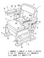
図1および図2に示すように、簡易便器(1) は、木製の便器本体(2) と、該便器本体(2) の上面に取付けられている折畳み開閉可能なクッション座部(3) と、該便器本体(2) の上面両側に設置されている左右一対の肘掛け(4) と、該便器本体(2) の両側後部に立設されているコの字状の背もたれ(5) と、該便器本体(2) の左右両側に取付けられている左右一対の高さ調節可能な脚部ユニット(6) とからなる。The present invention will be described with reference to an embodiment shown in FIGS.
As shown in FIGS. 1 and 2, the simple toilet (1) includes a wooden toilet body (2), and a cushion seat (3) that can be folded and opened attached to the upper surface of the toilet body (2). A pair of left and right armrests (4) installed on both sides of the upper surface of the toilet body (2), and a U-shaped backrest (5) standing on both sides of the toilet body (2). It comprises a pair of left and right height-adjustable leg units (6) attached to the left and right sides of the toilet body (2).
該肘掛け(4) は、下側短肘掛け台(7) と、該下側短肘掛け台(7) 上に重ねられる上側長肘掛け台(8) とからなる。該下側短肘掛け台(7) は、前後をコの字形支枠(9) によって便器本体(2) の両側に支持されており、該上側長肘掛け台(8) は、根端部をヒンジブラケット(10)によって該下側短肘掛け(7) の根端部に枢着され、前端から跳ね上げ可能とされている。
また、該下側短肘掛け台(7) 上面には図2に示すように突起部(11)が設けられており、該上側長肘掛け台(8) 下面には該突起部(11)を適嵌するための凹部(12)が設けられている。The armrest (4) is composed of a lower short armrest (7) and an upper long armrest (8) superimposed on the lower short armrest (7). The lower short armrest (7) is supported on both sides of the toilet body (2) by a U-shaped support frame (9) at the front and back, and the upper long armrest (8) is hinged at the root end. The bracket (10) is pivotally attached to the root end of the lower short armrest (7) and can be flipped up from the front end.
Further, as shown in FIG. 2, a projection (11) is provided on the upper surface of the lower short armrest (7), and the projection (11) is appropriately disposed on the lower surface of the upper long armrest (8). A recess (12) for fitting is provided.
図3に示すように、該肘掛け(4) の下側短肘掛け台(7) の先端部の所定個所にはボルト挿通孔(13)が設けられており、該上側長肘掛け台(8) の中間部下面の所定個所には埋込ナット(14)が埋設されている。
そして、該上側長肘掛け台(8) の埋込ナット(14)にはノブ付きロックボルト(15)が、該下側短肘掛け台(7) のボルト挿通孔(13)を挿通した状態で、該下側短肘掛け台(7) の下面から螺着されており、該下側短肘掛け台(7) の先端部と該上側長肘掛け台(8) の中間部とがロックされている。
該上側長肘掛け台(8) を跳ね上げる場合、該上側長肘掛け台(8) の埋込ナット(14)からノブ付きロックボルト(15)を取外すことによって、該下側短肘掛け台(7) の先端部と該上側長肘掛け台(8) の中間部とのロックを解除し、該上側長肘掛け台(8) を前端から跳ね上げることが出来る(図2参照)。As shown in FIG. 3, a bolt insertion hole (13) is provided at a predetermined position of the tip of the lower short armrest (7) of the armrest (4), and the upper long armrest (8) An embedded nut (14) is embedded at a predetermined location on the lower surface of the intermediate portion.
Then, with the embedded nut (14) of the upper long armrest (8), a lock bolt (15) with a knob is inserted through the bolt insertion hole (13) of the lower short armrest (7), It is screwed from the lower surface of the lower short armrest (7), and the tip of the lower short armrest (7) and the middle portion of the upper long armrest (8) are locked.
When the upper long armrest (8) is flipped up, the lower short armrest (7) is removed by removing the lock bolt (15) with a knob from the embedded nut (14) of the upper long armrest (8). Can be unlocked, and the upper long armrest (8) can be flipped up from the front end (see FIG. 2).
肘掛け(4) の下側短肘掛け台(7) の長さL1 は200mm〜250mmに設定されていることが望ましく、また、上側長肘掛け台(8) の長さL2 は450mm〜550mmに設定されていることが望ましく、そして、下側肘掛け台(7) の前方スペースL3 は250mm〜350mmに設定されていることが望ましい。
本実施例では、該下側短肘掛け台(7) の長さL1 は230mmに設定されており、また、該上側長肘掛け台(8) の長さL2 は500mmに設定されており、そして、該上下側肘掛け台(7) の前方スペースL3 は280mmに設定されている(図3参照)。The length L1 of the lower short armrest (7) of the armrest (4) is preferably set to 200 mm to 250 mm, and the length L2 of the upper long armrest (8) is set to 450 mm to 550 mm. The front space L3 of the lower armrest (7) is preferably set to 250 mm to 350 mm.
In this embodiment, the length L1 of the lower short armrest (7) is set to 230 mm, the length L2 of the upper long armrest (8) is set to 500 mm, and The front space L3 of the upper and lower armrests (7) is set to 280 mm (see FIG. 3).
更に、脚部ユニット(6) は、底板(16)と、該底板(16)から立設される前後一対の脚部(17)とからなり、該脚部(17)側面の所定個所には二個のボルト挿通孔(18)が縦列されており、一方、便器本体(2) の側面の所定個所には複数個の埋込ナット(19)が縦列して埋設されている(図3参照)。
そして、簡易便器(1) の高さ調節を行なう場合には、便器本体(2) の埋込ナット(19)のうち所望な高さ位置のものを選択し、該便器本体(2) の埋込ナット(19)の位置に脚部(17)のボルト挿通孔(18)の位置を合わせて固定ボルト(20)を螺着して固定する。Further, the leg unit (6) includes a bottom plate (16) and a pair of front and rear legs (17) standing from the bottom plate (16). Two bolt insertion holes (18) are arranged in a row, while a plurality of embedding nuts (19) are arranged in a row in a predetermined place on the side surface of the toilet body (2) (see FIG. 3). ).
When adjusting the height of the simple toilet (1), select the embedded nut (19) of the toilet body (2) at the desired height position and bury the toilet body (2). The position of the bolt insertion hole (18) of the leg portion (17) is aligned with the position of the insertion nut (19), and the fixing bolt (20) is screwed and fixed.
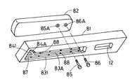
該上側長肘掛け台(8) は図4〜図9に示すように固定肘掛け台(81)と、該固定肘掛け台(81)上に前後に摺動可能に配置されている可動肘掛け台(82)と、固定板(82A) とからなり、該固定肘掛け台(81)の上面には長手方向に直線状ガイド溝(83)が形成されており、該直線状ガイド溝(83)の前端部には外側に分岐する円弧状ガイド溝(84)が連通されており、一方該可動肘掛け台(82)の下面に埋設されている前後一対のナット(85A,86A) には該ガイド溝(83,84) に摺動可能に嵌合する頭付きガイドピン(85,86) が螺着されている。
該固定肘掛け台(81)の上面には金属やプラスチック等からなる縁取り板(87)がビス(88)等で固定されており該縁取り板(87)には直線状ガイド溝(83A) と円弧状ガイド溝(84A) とが設けられ、該縁取り板(87)のガイド溝(83A,84A) の巾は上記可動肘掛け台(82)の頭付きガイドピン(85,86) の軸部径と略等しく設定され、該固定肘掛け台(81)のガイド溝(83,84) の巾は該頭付きガイドピン(85,86) の頭部径と略等しく設定されており、かくしてガイド溝(83,84) は蟻溝状であり、該可動肘掛け台(82)のガイドピン(85,86) がガイド溝(83,84) から抜出さないようにされている。
また図5に示すように該縁取り板(87)のガイド溝(83A) は固定肘掛け台(81)のガイド溝(83)の巾よりも狭く設定され後端部において巾広とされ、この巾広部分(831A)から該可動肘掛け台(82)のガイドピン(85,86) の頭部がガイド溝(83)に挿入出来るようになっている。As shown in FIGS. 4 to 9, the upper long armrest (8) includes a fixed armrest (81) and a movable armrest (82) that is slidably arranged on the fixed armrest (81) in the front-rear direction. ) And a fixing plate (82A), and a linear guide groove (83) is formed in the longitudinal direction on the upper surface of the fixed armrest (81), and the front end portion of the linear guide groove (83) An arcuate guide groove (84) branched outward is communicated with the pair of front and rear nuts (85A, 86A) embedded in the lower surface of the movable armrest (82). , 84) are screwed with headed guide pins (85, 86) which are slidably fitted.
An edge plate (87) made of metal, plastic, or the like is fixed to the upper surface of the fixed armrest (81) with a screw (88) or the like. The edge plate (87) has a linear guide groove (83A) and a circular shape. An arcuate guide groove (84A) is provided, and the width of the guide groove (83A, 84A) of the border plate (87) is the same as the shaft diameter of the headed guide pin (85, 86) of the movable armrest (82). The width of the guide groove (83, 84) of the fixed armrest (81) is set substantially equal to the head diameter of the headed guide pin (85, 86), and thus the guide groove (83 , 84) has a dovetail shape so that the guide pins (85, 86) of the movable armrest (82) are not pulled out from the guide grooves (83, 84).
Further, as shown in FIG. 5, the guide groove (83A) of the border plate (87) is set to be narrower than the width of the guide groove (83) of the fixed armrest (81) and is wide at the rear end. The heads of the guide pins (85, 86) of the movable armrest (82) can be inserted into the guide groove (83) from the wide part (831A).
上記簡易便器(1) は主として木材、合板、パーチクルボード等の木質材料によって構成されているが、プラスチック等を材料としてもよい。 The toilet bowl (1) is mainly composed of a wood material such as wood, plywood or particle board, but may be made of plastic or the like.
上記のような簡易便器(1) に使用者が側方のベッド等(図示せず)から移乗する場合には、簡易便器(1) のクッション座部(3) の高さとベッド上面の高さとが略同じ高さになるように簡易便器(1) の高さを調節し、移乗する側の便器本体(2) の肘掛け(4) の上側長肘掛け(8) を跳ね上げて撤去する。 When a user transfers to the toilet bowl (1) as described above from a side bed or the like (not shown), the height of the cushion seat (3) of the toilet bowl (1) and the height of the bed upper surface Adjust the height of the simple toilet (1) so that the height of the toilet bowl is approximately the same, and lift the upper long armrest (8) of the armrest (4) of the toilet body (2) on the transfer side and remove it.
上記のように、簡易便器(1) の肘掛け(4) の上側長肘掛け(8) が前端から跳ね上げ可能とされているので、使用者が側方から簡易便器(1) に移乗する際に該上側長肘掛け(8) が使用者の体に干渉することがなく、かつ、下側短肘掛け(7) に手を置いて体を支える手掛かりとすることが出来、そのため、足腰の弱い者であっても容易に移乗することが出来る。
また、使用者がいずれの側から簡易便器(1) に移乗する場合であっても、使用者は移乗する側の肘掛け(4) の上側長肘掛け(8) を跳ね上げればよく、移乗する向きに合わせて肘掛け(4) を取外して付け替える必要がない。As mentioned above, the upper long armrest (8) of the armrest (4) of the simple toilet (1) can be flipped up from the front end, so the user can transfer to the simple toilet (1) from the side. The upper long armrest (8) does not interfere with the user's body and can be used as a clue to support the body by placing a hand on the lower short armrest (7). Even if there is, it can be transferred easily.
In addition, regardless of which side the user is transferring to the toilet bowl (1), the user only has to flip up the upper long armrest (8) of the armrest (4) on the transfer side, It is not necessary to remove and replace the armrest (4) according to the situation.
該簡易便器(1) に使用者が移乗したら、図7に示すように肘掛け(4) の可動肘掛け台(82)を前方へ直線的に摺動させる。この際該可動肘掛け台(82)の前後一対のガイドピン(85,86) は縁取り板(87)のガイド溝(83A) 内を摺動し、かくして該可動肘掛け台(82)は左右にふれることなく前方へ摺動する。図9に示すように該可動肘掛け台(82)の前側のガイドピン(85)が縁取り板(87)のガイド溝(83A) の前端に当たる摺動前端に達したら、図8に示すように該可動肘掛け台(82)を90°内側へ回動させる。この際図9矢印に示すように該可動肘掛け台(82)の後側のガイドピン(86)はガイド溝(84A) 内を摺動する。そして該可動肘掛け台(82)を90°回動させて該固定肘掛け台(81)に直交した時、図9点線に示すように該可動肘掛け台(82)の後側のガイドピン(86)は縁取り板(87)のガイド溝(84A) の前端に当たり、該可動肘掛け台(82)がそれ以上回動することを阻止する。 When the user transfers to the simple toilet (1), the movable armrest (82) of the armrest (4) is linearly slid forward as shown in FIG. At this time, the pair of front and rear guide pins (85, 86) of the movable armrest (82) slides in the guide groove (83A) of the edge plate (87), and thus the movable armrest (82) touches left and right. Slide forward without any problems. As shown in FIG. 8, when the guide pin (85) on the front side of the movable armrest (82) reaches the sliding front end that hits the front end of the guide groove (83A) of the border plate (87) as shown in FIG. The movable armrest (82) is turned 90 ° inward. At this time, as shown by an arrow in FIG. 9, the guide pin (86) on the rear side of the movable armrest (82) slides in the guide groove (84A). When the movable armrest (82) is rotated by 90 ° and orthogonal to the fixed armrest (81), the guide pin (86) on the rear side of the movable armrest (82) as shown by the dotted line in FIG. Hits the front end of the guide groove (84A) of the border plate (87) and prevents the movable armrest (82) from rotating further.
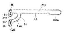
図8に示す状態で、使用者は排便し易い前かがみになって腕を該可動肘掛け台(82)に支え、安定な力を入れ易い状態で排便を行う。 In the state shown in FIG. 8, the user leans forward easily to defecate, supports the arm on the movable armrest (82), and defecates in a state where a stable force can be easily applied.
図10には固定肘掛け台(81)のガイド溝(83,84) 即ち縁取り板(87)のガイド溝(83A,84A) の前端部から直角に屈曲する屈曲部(83B,84B) が設けられている他の実施例が示される。
この実施例では前実施例のように可動肘掛け台(82)を90°回動させて、更にガイド溝(83,84) の屈曲部(83B,84B) 屈曲方向へ摺動させる。そうすると該可動肘掛け台(82)のガイドピン(85,86) は各々該屈曲部(83B,84B) に嵌入して該可動肘掛け台(82)の回動が固定される。FIG. 10 is provided with bent portions (83B, 84B) bent at right angles from the front ends of the guide grooves (83, 84) of the fixed armrest (81), that is, the guide grooves (83A, 84A) of the edge plate (87). Other embodiments are shown.
In this embodiment, the movable armrest (82) is rotated 90 ° as in the previous embodiment, and is further slid in the bending direction (83B, 84B) of the guide groove (83, 84). Then, the guide pins (85, 86) of the movable armrest (82) are fitted into the bent portions (83B, 84B), respectively, and the rotation of the movable armrest (82) is fixed.
図11〜図14には更に他の実施例が示される。本実施例にあっては、固定肘掛け台(81)にはガイド溝が上下貫通して設けられており、下側ガイド溝(831) と上側ガイド溝(832) とからなり、下側ガイド溝(831) の前端部には扇形拡径部(841) が形成されている。上側ガイド溝(832) は直線状で前端部には外側に分岐する円弧状ガイド溝(842) が分岐されており、上側ガイド溝(832,842) は下側ガイド溝(831) よりも巾狭で縁取り板(87)のガイド溝(83A,84A) と等しい巾に設定されており、該下側ガイド溝(831) の巾はガイドピン(85,86) の頭部径と略等しく設定されている。そして該下側ガイド溝(831) と該上側ガイド溝(832) との境界に形成される段部(89)に縁取り板(87)がビス(88)等によって下側から取付けられている。そしてガイドピン(85,86) は固定肘掛け台(81)の下側から下側ガイド溝(831) および上側ガイド溝(832) を介して可動肘掛け台(82)のナット(85A,86A) に螺着される。なお本実施例では固定板(82A) は省略されている。 Still another embodiment is shown in FIGS. In this embodiment, the fixed armrest (81) is provided with a guide groove extending vertically, and is composed of a lower guide groove (831) and an upper guide groove (832). A fan-shaped enlarged diameter portion (841) is formed at the front end of (831). The upper guide groove (832) is straight and has an arcuate guide groove (842) branched outward at the front end, and the upper guide groove (832,842) is narrower than the lower guide groove (831). The width is set equal to the guide groove (83A, 84A) of the edging plate (87), and the width of the lower guide groove (831) is set substantially equal to the head diameter of the guide pin (85, 86). Yes. An edge plate (87) is attached to the stepped portion (89) formed at the boundary between the lower guide groove (831) and the upper guide groove (832) from below with screws (88) or the like. The guide pins (85, 86) are moved from the lower side of the fixed armrest (81) to the nut (85A, 86A) of the movable armrest (82) via the lower guide groove (831) and the upper guide groove (832). Screwed. In the present embodiment, the fixing plate (82A) is omitted.
上記実施例以外、本発明の固定肘掛け台と可動肘掛け台とからなる構造は片側の肘掛けにのみ適用されてもよい。 The structure which consists of a fixed armrest and a movable armrest of this invention other than the said Example may be applied only to the armrest of one side.
本発明の簡易便器にあっては、老人や病人のような体力のない人でも、排便が容易に出来る。 In the simple toilet of the present invention, even a person without physical strength such as an elderly person or a sick person can easily defecate.
図1〜図10は本発明の実施例を示すものである。
1 簡易便器
2 便器本体
4 肘掛け
8 肘掛け台(上側長肘掛け台)
9 支枠
81 固定肘掛け台
82 可動肘掛け台
82A 固定板
83 直線状ガイド溝
831 下側ガイド溝
832 上側ガイド溝
84,842 円弧状ガイド溝
83B,84B 係止ガイド溝(屈曲部)
85,86 ガイドピン
87 縁取り板1 Simple toilet
2 Toilet body
4 armrests
8 Armrest (upper long armrest)
9 Support frame
81 Fixed armrest
82 Movable armrest
82A fixed plate
83 Linear guide groove
831 Lower guide groove
832 Upper guide groove
84,842 Arc guide groove
83B, 84B Locking guide groove (bent part)
85,86 guide pins
87 Border plate
Claims (3)
Translated fromJapanese該肘掛けは支枠と、該支枠に支持されている肘掛け台とからなり、
両方または一方の肘掛けの該肘掛け台は固定肘掛け台と、該固定肘掛け台上に前後に摺動可能に配置されている可動肘掛け台と、該固定肘掛け台の根端部上面に固設され、該可動肘掛け台の上面レベルを略等しくする固定板と、からなり、
該固定肘掛け台の上面には長手方向に直線状ガイド溝が形成されており、該直線状ガイド溝の前端部には外側に分岐する円弧状ガイド溝が連通されており、
一方該可動肘掛け台の下面からは該ガイド溝に摺動可能に嵌合するガイドピンが前後一対突設されており、該可動肘掛け台が該固定肘掛け台を摺動して摺動前端に達した時、該可動肘掛け台を内側に回動せしめれば該後側ガイドピンが該円弧状ガイド溝にガイドされて摺動し、かくして該可動肘掛け台は該固定肘掛け台に対して略直交位置に回動が可能にされている
ことを特徴とする簡易便器。A toilet with standing armrests from both sides of the upper surface of the toilet body,
The armrest includes a support frame and an armrest supported by the support frame.
The armrests of both or one armrest are fixed to a fixed armrest, a movable armrest that is slidable back and forth on thefixed armrest, and an upper surface of the root end of the fixed armrest; A fixed plate that substantially equalizes the upper surface level of the movable armrest ,
A linear guide groove is formed in the longitudinal direction on the upper surface of the fixed armrest, and an arcuate guide groove branched outward is communicated with the front end of the linear guide groove.
On the other hand, a pair of front and rear guide pins slidably fitted into the guide groove are provided from the lower surface of the movable armrest, and the movable armrest slides on the fixed armrest to reach the sliding front end. When the movable armrest is rotated inward, the rear guide pin is guided and slid by the arcuate guide groove, so that the movable armrest is positioned substantially orthogonal to the fixed armrest. A simple toilet, characterized in that it can be rotated.
Priority Applications (1)
| Application Number | Priority Date | Filing Date | Title |
|---|---|---|---|
| JP2004009991AJP4435583B2 (en) | 2004-01-19 | 2004-01-19 | Simple toilet |
Applications Claiming Priority (1)
| Application Number | Priority Date | Filing Date | Title |
|---|---|---|---|
| JP2004009991AJP4435583B2 (en) | 2004-01-19 | 2004-01-19 | Simple toilet |
Publications (2)
| Publication Number | Publication Date |
|---|---|
| JP2005198928A JP2005198928A (en) | 2005-07-28 |
| JP4435583B2true JP4435583B2 (en) | 2010-03-17 |
Family
ID=34822846
Family Applications (1)
| Application Number | Title | Priority Date | Filing Date |
|---|---|---|---|
| JP2004009991AExpired - Fee RelatedJP4435583B2 (en) | 2004-01-19 | 2004-01-19 | Simple toilet |
Country Status (1)
| Country | Link |
|---|---|
| JP (1) | JP4435583B2 (en) |
Families Citing this family (5)
| Publication number | Priority date | Publication date | Assignee | Title |
|---|---|---|---|---|
| JP6460702B2 (en)* | 2014-08-22 | 2019-01-30 | 株式会社 シコク | Handrail device for toilet |
| CN104594483B (en)* | 2015-01-30 | 2016-03-30 | 司志刚 | Wall hanging folding ergonomics multi-function pan closet |
| JP2016202225A (en)* | 2015-04-15 | 2016-12-08 | 積水ホームテクノ株式会社 | Handrail structure of toilet bowl and movable toilet bowl |
| JP2017042503A (en)* | 2015-08-28 | 2017-03-02 | 協立工業株式会社 | Hand rail for toilet bowl |
| JP6998167B2 (en)* | 2017-09-22 | 2022-02-10 | パラマウントベッド株式会社 | Handrail for toilet bowl |
- 2004
- 2004-01-19JPJP2004009991Apatent/JP4435583B2/ennot_activeExpired - Fee Related
Also Published As
| Publication number | Publication date |
|---|---|
| JP2005198928A (en) | 2005-07-28 |
Similar Documents
| Publication | Publication Date | Title |
|---|---|---|
| US8864233B2 (en) | Tattoo chair | |
| KR101715092B1 (en) | A Front height adjustable sliding folding chair | |
| US3672722A (en) | Invalid chair having adjustable headrest seat and footrest | |
| JP4435583B2 (en) | Simple toilet | |
| JP2010005077A (en) | Auxiliary handrail apparatus | |
| CA1324313C (en) | Rocking chair | |
| KR101496727B1 (en) | A folding type chair without legs | |
| KR100991359B1 (en) | Chair with protruding back plate to support lumbar spine | |
| JP4289957B2 (en) | Shower folding chair | |
| JP4498980B2 (en) | Portable toilet | |
| JP2004313512A (en) | Simple toilet | |
| JP4405228B2 (en) | Simple toilet | |
| JP4477852B2 (en) | Simple toilet | |
| JP2004129721A (en) | Chair having memo stand | |
| JP2003102581A (en) | Chair | |
| JP3836690B2 (en) | Chair | |
| JP3219802U (en) | wheelchair | |
| JP3295798B2 (en) | Infusion / dialysis chair | |
| JP4146663B2 (en) | Chair | |
| JPS641124B2 (en) | ||
| JP4461482B2 (en) | Portable toilet with handrail | |
| JP4405227B2 (en) | Simple toilet armrest structure and simple toilet | |
| JP3037917U (en) | Chair | |
| JP3437948B2 (en) | Table | |
| JP4430129B1 (en) | Seat chair that can also be used as a back stretcher |
Legal Events
| Date | Code | Title | Description |
|---|---|---|---|
| A621 | Written request for application examination | Free format text:JAPANESE INTERMEDIATE CODE: A621 Effective date:20061107 | |
| A131 | Notification of reasons for refusal | Free format text:JAPANESE INTERMEDIATE CODE: A131 Effective date:20090909 | |
| A521 | Written amendment | Free format text:JAPANESE INTERMEDIATE CODE: A523 Effective date:20091102 | |
| TRDD | Decision of grant or rejection written | ||
| A01 | Written decision to grant a patent or to grant a registration (utility model) | Free format text:JAPANESE INTERMEDIATE CODE: A01 Effective date:20091204 | |
| A01 | Written decision to grant a patent or to grant a registration (utility model) | Free format text:JAPANESE INTERMEDIATE CODE: A01 | |
| A61 | First payment of annual fees (during grant procedure) | Free format text:JAPANESE INTERMEDIATE CODE: A61 Effective date:20091224 | |
| R150 | Certificate of patent or registration of utility model | Free format text:JAPANESE INTERMEDIATE CODE: R150 | |
| FPAY | Renewal fee payment (event date is renewal date of database) | Free format text:PAYMENT UNTIL: 20130108 Year of fee payment:3 | |
| FPAY | Renewal fee payment (event date is renewal date of database) | Free format text:PAYMENT UNTIL: 20130108 Year of fee payment:3 | |
| S531 | Written request for registration of change of domicile | Free format text:JAPANESE INTERMEDIATE CODE: R313531 | |
| FPAY | Renewal fee payment (event date is renewal date of database) | Free format text:PAYMENT UNTIL: 20130108 Year of fee payment:3 | |
| R360 | Written notification for declining of transfer of rights | Free format text:JAPANESE INTERMEDIATE CODE: R360 | |
| FPAY | Renewal fee payment (event date is renewal date of database) | Free format text:PAYMENT UNTIL: 20130108 Year of fee payment:3 | |
| R370 | Written measure of declining of transfer procedure | Free format text:JAPANESE INTERMEDIATE CODE: R370 | |
| LAPS | Cancellation because of no payment of annual fees |