JP4432840B2 - Vibration type actuator - Google Patents
Vibration type actuatorDownload PDFInfo
- Publication number
- JP4432840B2 JP4432840B2JP2005180375AJP2005180375AJP4432840B2JP 4432840 B2JP4432840 B2JP 4432840B2JP 2005180375 AJP2005180375 AJP 2005180375AJP 2005180375 AJP2005180375 AJP 2005180375AJP 4432840 B2JP4432840 B2JP 4432840B2
- Authority
- JP
- Japan
- Prior art keywords
- case
- actuator
- main body
- fixed
- body case
- Prior art date
- Legal status (The legal status is an assumption and is not a legal conclusion. Google has not performed a legal analysis and makes no representation as to the accuracy of the status listed.)
- Expired - Fee Related
Links
Images


Classifications
- H—ELECTRICITY
- H02—GENERATION; CONVERSION OR DISTRIBUTION OF ELECTRIC POWER
- H02N—ELECTRIC MACHINES NOT OTHERWISE PROVIDED FOR
- H02N2/00—Electric machines in general using piezoelectric effect, electrostriction or magnetostriction
- H02N2/10—Electric machines in general using piezoelectric effect, electrostriction or magnetostriction producing rotary motion, e.g. rotary motors
- H02N2/12—Constructional details
- H—ELECTRICITY
- H02—GENERATION; CONVERSION OR DISTRIBUTION OF ELECTRIC POWER
- H02K—DYNAMO-ELECTRIC MACHINES
- H02K33/00—Motors with reciprocating, oscillating or vibrating magnet, armature or coil system
- H02K33/02—Motors with reciprocating, oscillating or vibrating magnet, armature or coil system with armatures moved one way by energisation of a single coil system and returned by mechanical force, e.g. by springs
- A—HUMAN NECESSITIES
- A61—MEDICAL OR VETERINARY SCIENCE; HYGIENE
- A61C—DENTISTRY; APPARATUS OR METHODS FOR ORAL OR DENTAL HYGIENE
- A61C17/00—Devices for cleaning, polishing, rinsing or drying teeth, teeth cavities or prostheses; Saliva removers; Dental appliances for receiving spittle
- A61C17/16—Power-driven cleaning or polishing devices
- A61C17/22—Power-driven cleaning or polishing devices with brushes, cushions, cups, or the like
- A61C17/32—Power-driven cleaning or polishing devices with brushes, cushions, cups, or the like reciprocating or oscillating
- A61C17/34—Power-driven cleaning or polishing devices with brushes, cushions, cups, or the like reciprocating or oscillating driven by electric motor
- A61C17/3409—Power-driven cleaning or polishing devices with brushes, cushions, cups, or the like reciprocating or oscillating driven by electric motor characterized by the movement of the brush body
- A61C17/3445—Translation along the axis of the toothbrush handle
- H—ELECTRICITY
- H02—GENERATION; CONVERSION OR DISTRIBUTION OF ELECTRIC POWER
- H02K—DYNAMO-ELECTRIC MACHINES
- H02K33/00—Motors with reciprocating, oscillating or vibrating magnet, armature or coil system
Landscapes
- Engineering & Computer Science (AREA)
- Power Engineering (AREA)
- Health & Medical Sciences (AREA)
- Public Health (AREA)
- Epidemiology (AREA)
- Life Sciences & Earth Sciences (AREA)
- Animal Behavior & Ethology (AREA)
- General Health & Medical Sciences (AREA)
- Dentistry (AREA)
- Veterinary Medicine (AREA)
- Reciprocating, Oscillating Or Vibrating Motors (AREA)
- Brushes (AREA)
- Apparatuses For Generation Of Mechanical Vibrations (AREA)
- General Electrical Machinery Utilizing Piezoelectricity, Electrostriction Or Magnetostriction (AREA)
- Control Of Throttle Valves Provided In The Intake System Or In The Exhaust System (AREA)
- Fuel-Injection Apparatus (AREA)
- Actuator (AREA)
Abstract
Description
Translated fromJapanese本発明は、小型化、軽量化およびコストダウン化が図れるようにした低振動の振動型アクチュエータに関する。 The present invention relates to a low-vibration vibration type actuator that can be reduced in size, weight, and cost.
従来、可動部と、この可動部を電磁力で往復駆動させる電磁駆動部とを備えて、電気カミソリや電動歯ブラシ等の駆動部に用いられる振動型アクチュエータがある。 2. Description of the Related Art Conventionally, there is a vibration type actuator that includes a movable portion and an electromagnetic drive portion that reciprocally drives the movable portion with an electromagnetic force and is used in a drive portion such as an electric razor or an electric toothbrush.
特許文献1の振動型アクチュエータ(リニアオシレータ)は、往復動自在の可動部と、この可動部を収納するケースと、このケースに可動に支持された振幅制御錘とを備えて、可動部および振幅制御錘は、リニアオシレータの共振周波数もしくはその近傍の周波数で往復動させるものである。 The vibration type actuator (linear oscillator) of Patent Literature 1 includes a movable part that can reciprocate, a case that houses the movable part, and an amplitude control weight that is movably supported by the case. The control weight is reciprocated at the resonance frequency of the linear oscillator or a frequency in the vicinity thereof.
具体的には、図5(a)に示すように、可動部は、鉄材などの磁性体にて形成された円柱状のプランジャー1と、出力軸2とで構成されて、プランジャー1は、軸方向の両端付近が大径に、中央部が小径に形成されて、出力軸2が貫通固定されていて、プランジャー1の外周には環状のコイル3が配設されている。 Specifically, as shown in FIG. 5 (a), the movable part is composed of a cylindrical plunger 1 formed of a magnetic material such as iron, and an
また、可動部を収納するシールドケース4の内面に固定されたコイル3の軸方向両側には、コイル3に対して対称に着磁された環状の永久磁石5,6が配設されて、これら永久磁石5,6とコイル3との間には環状のヨーク7,8が配設され、永久磁石5,6のヨーク7,8と反対側の位置には環状のヨーク9,10が配設されている。前記コイル3、永久磁石5,6およびヨーク7〜10とで、電磁駆動部を構成する。 In addition, annular
さらに、プランジャー1の一端面とシールドケース4との間には第1ばね11が配設され、プランジャー1の他端面とシールドケース4との間には、第2ばね12と振幅制御錘14と第3ばね13がこの順で配設されている。ばね11〜13は、可動部を軸方向に付勢してばね振動系を構成する。 Further, a
そして、コイル3に電流を流していない時は、永久磁石5,6がヨーク7〜10を介してプランジャー1に及ぼす磁力と、ばね11〜13のばね力とが釣り合う図示の位置でプランジャー1は静止している。この状態からコイル3に一方向電流を流すと、2つの永久磁石5,6のうちの一方の磁束が弱められるために、ばねに抗してプランジャー1は、他方の磁石側に移動し、コイル3に逆方向電流を流すと、ばねに抗してプランジャー1は逆方向に移動することから、コイル3に交番電流を流すことで、プランジャー1とともに出力軸2が軸方向に往復動(振動…矢印a参照)するようになる。 When no current is flowing through the coil 3, the plunger is moved at the position shown in the figure where the magnetic force exerted on the plunger 1 by the
ここで、特許文献1では、プランジャー1と出力軸2とを備えてなる可動部と、振幅制御錘14との軸方向の運動について着目した場合、ばね11〜13の存在によってばね振動系モデルとして取り扱うことができるとし、可動部と振幅制御錘14と固定部の質量、ばねのばね定数と減衰係数等に基づいて、ばね振動系における各質点の自由振動時の運動方程式で、2つの解の周波数f1,f2を求めている。 Here, in Patent Document 1, when attention is paid to the movement in the axial direction of the movable portion including the plunger 1 and the
この2つの解の周波数f1,f2は共振周波数であり、第1次(低次側)の固有振動数f1の振動モードは、可動部と振幅制御錘14とが同位相で運動する振動モード、第2次(高次側)の固有振動数f2の振動モードは、可動部と振幅制御錘14とが逆位相で運動する振動モードである。 The frequencies f1 and f2 of these two solutions are resonance frequencies, and the vibration mode of the first-order (low-order) natural frequency f1 is a vibration mode in which the movable portion and the
そして、第2次の固有振動数f2近傍の周波数の電流をコイル3に印加することで、可動部に軸方向の往復運動を行わせた場合、逆位相の運動を行う振幅制御錘14は、可動部の慣性力を打ち消すことができ、逆に振幅制御錘14の慣性力を可動部が打ち消すことになる。更に、この状態では2つの質点である可動部と振幅制御錘14の慣性力が釣り合うように運動しようとし、カウンタ動作による慣性力の打ち消し合い効果は大きく、このために固定部側へ伝わる2質点(可動部と振幅制御錘14)からの力は極小となり、よって、リニアオシレータにおける振動は極小となる、つまり、低振動のリニアオシレータを得ることができる。 Then, by applying a current having a frequency in the vicinity of the second natural frequency f2 to the coil 3, when the movable part is caused to reciprocate in the axial direction, the
一方、特許文献2の振動型アクチュエータ(バイブレータ装置)は、図5(b)に示すように、回転可能な回転円板16と、軸方向に移動可能な軸動円板17とを対向配置し、これら各円板16,17の対向面に、円周方向に交互に異なる磁極の永久磁石(本例では、各4極)18,19を配列して、回転円板16を電動モータ20で回転させることにより、軸動円板17に対して磁気的に吸引・反発を行わせることで、軸動円板17とともに出力軸21が軸方向に往復動(振動…矢印a参照)するようになる。
しかしながら、特許文献1では、振幅制御錘14を配置するためのスペースが必要であるので小型化が困難であり、振幅制御錘14が必要であるので軽量化やコストダウン化が困難であった。 However, in Patent Document 1, it is difficult to reduce the size because a space for arranging the
また、特許文献2では、特許文献1のような振幅制御錘は無いものの、低振動とするための対策が要望されている。 Further, in
本発明は、前記問題を解消するためになされたもので、小型化、軽量化およびコストダウン化が図れるようにした低振動の振動型アクチュエータを提供することを目的とするものである。 The present invention has been made to solve the above problems, and an object of the present invention is to provide a low-vibration vibration type actuator that can be reduced in size, weight, and cost.
前記課題を解決するために、本発明の第1の手段は、可動部と、この可動部を電磁力で往復駆動させる電磁駆動部とを備えた振動型アクチュエータにおいて、前記可動部と電磁駆動部とを本体ケース内に往復動可能に収納して、この本体ケース内で、前記可動部と電磁駆動部を逆位相で往復動させるようにしたものであり、前記可動部は、プランジャーと、プランジャーに固定した出力軸とで構成し、前記電磁駆動部は、プランジャーと出力軸とを収納するシールドケースと、シールドケースの内周面に固定したコイルと、コイルの軸方向の両側方に固定した永久磁石と、永久磁石のコイル側に固定したヨークと、永久磁石のコイルの反対側に固定したヨークと、プランジャーの一端部とシールドケースの一端部との間に介設したばねと、プランジャーの他端部とシールドケースの他端部との間に介設したばねとで構成して、この各ばねにより、シールドケース内で可動部を軸方向に往復動可能に弾性支持する一方、前記シールドケースは、本体ケース内に収納して、シールドケースの一端部と本体ケースの一端部の間、およびシールドケースの他端部と本体ケースの他端部の間にばねをそれぞれ介設して、この各ばねにより、本体ケース内でシールドケースを軸方向に往復動可能に弾性支持することを特徴とする振動型アクチュエータを提供するものである。In order to solve the above-mentioned problems,the first means of the present invention is a vibration type actuator comprising a movable part and an electromagnetic drive part that reciprocally drives the movable part with electromagnetic force. In the main body case so that the movable portion and the electromagnetic drive portion are reciprocated in opposite phases, and the movable portion includes a plunger, The electromagnetic drive unit includes a shield case that houses the plunger and the output shaft, a coil that is fixed to the inner peripheral surface of the shield case, and both sides in the axial direction of the coil. A permanent magnet fixed to the coil, a yoke fixed to the coil side of the permanent magnet, a yoke fixed to the opposite side of the permanent magnet coil, and a spring interposed between one end of the plunger and one end of the shield case And The spring is interposed between the other end of the flanger and the other end of the shield case, and each of the springs elastically supports the movable part in the shield case so as to reciprocate in the axial direction. The shield case is housed in a body case, and springs are interposed between one end of the shield case and one end of the body case, and between the other end of the shield case and the other end of the body case, respectively. Thus , a vibration type actuator is provided by whicheach of the springs elastically supports the shield case so as to reciprocate in the axial direction within the main body case .
本発明の第2の手段は、可動部と、この可動部を電磁力で往復駆動させる電磁駆動部とを備えた振動型アクチュエータにおいて、前記可動部と電磁駆動部とを本体ケース内に往復動可能に収納して、この本体ケース内で、前記可動部と電磁駆動部とを逆位相で往復動させるようにしたものであり、前記可動部は、出力軸と、出力軸に固定したヨークと、このヨークに固定した交互に異なる磁極の永久磁石とで構成し、前記電磁駆動部は、アクチュエータケースと、アクチュエータケースに固定した電動モータと、電動モータの出力軸に固定したヨークと、このヨークに固定した交互に異なる磁極の永久磁石と、出力軸のセンタープレートの一端部とアクチュエータケースの一端部との間に介設したばねと、出力軸のセンタープレートの他端部とアクチュエータケースの他端部との間に介設したばねとで構成して、この各ばねにより、アクチュエータケース内で可動部を軸方向に往復動可能に弾性支持する一方、前記アクチュエータケースは、電動モータとともに回り止め状態で本体ケース内に収納して、アクチュエータケースの一端部と本体ケースの一端部の間、およびアクチュエータケースの他端部と本体ケースの他端部の間にばねをそれぞれ介設して、この各ばねにより、本体ケース内でアクチュエータケースを軸方向に往復動可能に弾性支持することを特徴とする振動型アクチュエータを提供するものである。The second means of the present invention is a vibration type actuator comprising a movable part and an electromagnetic drive part for reciprocatingly driving the movable part with electromagnetic force. The movable part and the electromagnetic drive part are reciprocated in a main body case. The movable portion and the electromagnetic drive portion are reciprocated in opposite phases in the main body case. The movable portion includes an output shaft, a yoke fixed to the output shaft, The electromagnetic drive unit includes an actuator case, an electric motor fixed to the actuator case, a yoke fixed to the output shaft of the electric motor, and the yoke. Permanent magnets of different magnetic poles fixed to each other, a spring interposed between one end of the center plate of the output shaft and one end of the actuator case, and the other end of the center plate of the output shaft The spring is interposed between the other end of the actuator case, and each of the springs elastically supports the movable part in the actuator case so as to reciprocate in the axial direction. It is housed in the body case with the motor in a non-rotating state, and springs are interposed between one end of the actuator case and one end of the body case, and between the other end of the actuator case and the other end of the body case, respectively. Thus , the vibration type actuator is characterizedin that the actuator case is elastically supported by the springs so as to reciprocate in the axial direction within the main body case .
本発明によれば、可動部と逆位相で往復動する電磁駆動部が振幅制御錘の役割を兼ねるから、振幅制御錘を別に配置する必要が無くなるので、振幅制御錘を配置するためのスペースが不要となって小型化でき、振幅制御錘自体も不要となって軽量化やコストダウン化が図れるようになる。 According to the present invention, since the electromagnetic driving part that reciprocates in the opposite phase to the movable part also serves as the amplitude control weight, there is no need to separately arrange the amplitude control weight, so there is no space for placing the amplitude control weight. It becomes unnecessary and can be reduced in size, and the amplitude control weight itself becomes unnecessary, so that weight reduction and cost reduction can be achieved.
以下、本発明を実施するための最良の形態について、図面を参照しながら詳細に説明する。なお、背景技術と同一構成・作用の箇所は、同一番号を付して詳細な説明を省略する。 Hereinafter, the best mode for carrying out the present invention will be described in detail with reference to the drawings. Note that portions having the same configuration and operation as those of the background art are denoted by the same reference numerals, and detailed description thereof is omitted.
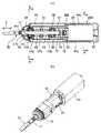
図1は、第1実施形態の振動型アクチュエータ26Aであり、特許文献1に対応するタイプである。プランジャー1と、このプランジャー1に固定された出力軸2とで可動部27が構成され、プランジャー1と出力軸2とは円筒状のシールドケース4内に収納されて、出力軸2がシールドケース4の両端部の貫通穴4aに往復動可能に貫通されている。 FIG. 1 shows a vibration type actuator 26 </ b> A of the first embodiment, which is a type corresponding to Patent Document 1. The
前記シールドケース4の内周面には環状のコイル3が固定され、このコイル3の軸方向の両側方には、環状の永久磁石5,6が固定され、永久磁石5,6のコイル3側に環状のヨーク7,8が固定され、永久磁石5,6のコイル3の反対側に環状のヨーク9,10が固定されている。 An annular coil 3 is fixed to the inner peripheral surface of the
さらに、プランジャー1の一端面とシールドケース4の一端部との間にばね11が介設され、プランジャー1の他端面とシールドケース4の他端部との間にばね12が介設されて、シールドケース4内で、プランジャー1とともに出力軸2を軸方向に往復動可能に弾性支持している。 Further, a
そして、コイル3に電流を流していない時は、永久磁石5,6がヨーク7〜10を介してプランジャー1に及ぼす磁力と、ばね11,12のばね力とが釣り合う図示の位置でプランジャー1は静止している。 When no current is flowing through the coil 3, the plunger is moved at the position shown in the figure where the magnetic force exerted on the plunger 1 by the
前記コイル3、シールドケース4、永久磁石5,6、ヨーク7〜10およびばね11,12等で電磁駆動部28が構成される。 The coil 3, the
前記シールドケース4は、円筒状の本体ケース30内に収納されて、可動部27の出力軸2が本体ケース30の両端部の貫通穴30aに往復動可能に貫通されている。 The
また、シールドケース4の一端部と本体ケース30の一端部の間にばね31が介設され、シールドケース4の他端部と本体ケース30の他端部との間にばね32が介設されて、本体ケース30内で、シールドケース4を軸方向に往復動可能に弾性支持している。 A
そして、コイル3に電流を流していない時は、ばね31,32のばね力が釣り合う図示の位置でシールドケース4は静止している。 When no current is passed through the coil 3, the
前記ばね11,12は、可動部27を軸方向に付勢するばね振動系を構成し、前記ばね31,32は、シールドケース4を軸方向に付勢するばね振動系を構成する。ここで、質量の大きな電磁駆動部28は、背景技術の振幅制御錘14と同様の「錘」として機能する。 The
図1の状態からコイル3に一方向電流を流すと、2つの永久磁石5,6のうちの一方の磁束が弱められるために、ばねに抗してプランジャー1は、他方の磁石側に移動し、コイル3に逆方向電流を流すと、ばねに抗してプランジャー1は逆方向に移動することから、コイル3に交番電流を流すことで、プランジャー1とともに出力軸2が軸方向に往復動(振動…矢印a参照)するようになる。 When a one-way current is passed through the coil 3 from the state of FIG. 1, the magnetic flux of one of the two
ここで、特許文献1と同様に、可動部27と電磁駆動部28とが逆位相で運動する振動モードである第2次(高次側)の固有振動数f2近傍の周波数の電流をコイル3に印加することで、可動部27に軸方向の往復運動を行わせた場合、逆位相の運動を行う電磁駆動部28は、可動部27の慣性力を打ち消すことができ、逆に電磁駆動部28の慣性力を可動部27が打ち消すことになる。更に、この状態では2つの質点である可動部27と電磁駆動部28の慣性力が釣り合うように運動しようとし、カウンタ動作による慣性力の打ち消し合い効果は大きく、このために固定部側へ伝わる2質点(可動部27と電磁駆動部28)からの力は極小となり、よって、振動型アクチュエータ26Aにおける振動は極小となる、つまり、低振動の振動型アクチュエータ26Aを得ることができる。 Here, similarly to Patent Document 1, a current having a frequency in the vicinity of the secondary (higher-order) natural frequency f2, which is a vibration mode in which the
第1実施形態の振動型アクチュエータ26Aでは、電磁駆動部28が特許文献1の振幅制御錘14の役割を兼ねるから、振幅制御錘14を別に配置する必要が無くなるので、振幅制御錘14を配置するためのスペースが不要となって小型化でき、振幅制御錘14自体も不要となって軽量化やコストダウン化が図れるようになる。 In the
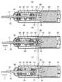
図2〜図4は、第2実施形態の振動型アクチュエータ26Bであり、特許文献2に対応するタイプである。出力軸21と、この出力軸21の他端部(後端部)に固定された軸動円板(ヨーク)17と、この軸動円板17に固定された、円周方向に交互に異なる磁極の永久磁石19とで可動部35が構成され、出力軸21と軸動円板17および永久磁石19とは、円筒状のアクチュエータケース37内に収納されている。前記出力軸21は、アクチュエータケース37内に固定された一対のベアリング38,39で往復動可能に支持されて、出力軸21の一端部(先端部)がアクチュエータケース37の貫通穴37aに往復動可能に貫通されている。 2 to 4 show the vibration type actuator 26B of the second embodiment, which is a type corresponding to Patent
前記アクチュエータケース37内には、一対のベアリング38,39の間に中空部37bが形成され、この中空部37b内において、前記出力軸21にセンタープレート40が固定されるとともに、各ベアリング38,39側にばね受け41a,41bがそれぞれ配置されている。各ばね受け41a,41bとセンタープレート40との間に、ばね42,43がそれぞれ介設されて、アクチュエータケース37内で、出力軸21を軸方向に往復動可能に弾性支持している。そして、ばね42,43のばね力が釣り合う図2の位置で出力軸21は静止している。 In the
前記アクチュエータケース37の他端部には電動モータ20が固定され、この電動モータ20の出力軸20aに固定された回転円板(ヨーク)16に、前記出力軸21の永久磁石19と対向する、円周方向に交互に異なる磁極の永久磁石18が固定されている。 The
前記アクチュエータケース37、電動モータ20,永久磁石18、ばね42,43等で電磁駆動部36が構成される。 The
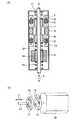
前記電動モータ20とともにアクチュエータケース37は、円筒状の本体ケース44内に収納されて、可動部35の出力軸21の一端部が本体ケース44の貫通穴44aに往復動可能に貫通されている。 The
前記アクチュエータケース37の一端部には環状の金属製摺動板45が嵌装され、この摺動板45に対応する本体ケース44内には、図4(d)に示すように、円周上等角度間隔(本例では120度間隔)で三角形状のリブ44bが突出されて、各リブ44bで摺動板45を支承することで、本体ケース44内で、アクチュエータケース37を軸方向に往復動可能に支持するようになる。この摺動板45によって、リブ44bとアクチュエータケース37との間の摺動がスムーズになり、リブ44bの摩耗も低減することができる。なお、図4(e)に示すように、円周上等角度間隔(本例では90度間隔)で半円形状のリブ44bを突出して、各リブ44bで摺動板45を支承するようにしても良い。 An annular
前記電動モータ20は、正面視で小判形状に形成されて、この電動モータ20に対応する前記本体ケース44内の上下位置には、図4(a)に示すように三角形状のリブ44cが突出されて、各リブ44cで電動モータ20を回り止めしながら支承することで、本体ケース44内で、電動モータ20を軸方向に往復動可能に支持するようになる。 The
換言すれば、本体ケース44内で、電動モータ20を一体化したアクチュエータケース37が軸方向に往復動可能に支持されることになる。 In other words, the
なお、図4(b)に示すように、本体ケース44内の左右位置に三角形状のリブ44dを突出して、各リブ44dで電動モータ20を回り止めしながら支承することもでき、図4(c)のように、本体ケース44内を小判形状に形成して、電動モータ20を回り止めしながら支承することもできる。 As shown in FIG. 4B,
また、アクチュエータケース37の一端部と本体ケース44の一端部の間にばね46が介設され、電動モータ20の他端部と本体ケース30の他端部との間にばね47が介設されて、本体ケース44内で、電動モータ20とともにアクチュエータケース37を軸方向に往復動可能に弾性支持している。そして、ばね46,47のばね力が釣り合う図2の位置で電動モータ20とともにアクチュエータケース37は静止している。なお、ばね46,47をコイルばねでは無く、板ばねやトーションバーとすれば、アクチュエータケース37を回り止めできるので、前述のような電動モータ20の回り止めは不要になる。 A
前記ばね42,43は、可動部35を軸方向に付勢するばね振動系を構成し、前記ばね46,47は、電動モータ20とともにアクチュエータケース37を軸方向に付勢するばね振動系を構成する。ここで、質量の大きな電磁駆動部36は、背景技術の振幅制御錘14と同様の「錘」として機能する。 The
そして、図3(a)の状態から電動モータ20を回転駆動させると、回転円板16とともに永久磁石18が回転して、軸動円板17の永久磁石19に対して磁気的に吸引・反発を行わせることで、図3(b)(c)のように、軸動円板17とともに出力軸21が軸方向に往復動(振動…矢印a参照)するようになる。 When the
この場合、図3(b)のように、永久磁石18,19が磁気的に吸引を行う時は、可動部35は後方に移動すると同時に、電磁駆動部36が前方に移動し、図3(c)のように、永久磁石18,19が磁気的に反発を行う時は、可動部35は前方に移動すると同時に、電磁駆動部36が後方に移動する。つまり、可動部35に軸方向の往復運動を行わせた場合、逆位相の運動を行う電磁駆動部36は、可動部35の慣性力を打ち消すことができ、逆に電磁駆動部36の慣性力を可動部35が打ち消すことになる。更に、この状態では2つの質点である可動部35と電磁駆動部36の慣性力が釣り合うように運動しようとし、カウンタ動作による慣性力の打ち消し合い効果は大きく、このために固定部側へ伝わる2質点(可動部35と電磁駆動部36)からの力は極小となり、よって、振動型アクチュエータ26Bにおける振動は極小となる、つまり、低振動の振動型アクチュエータ26Bを得ることができる。 In this case, as shown in FIG. 3B, when the
第2実施形態の振動型アクチュエータ26Bでは、電磁駆動部36が特許文献1の振幅制御錘14の役割を兼ねるから、振幅制御錘14を別に配置する必要が無くなるので、振幅制御錘14を配置するためのスペースが不要となって小型化でき、振幅制御錘14自体も不要となって軽量化やコストダウン化が図れるようになる。 In the vibration type actuator 26B of the second embodiment, since the
前記振動型アクチュエータ26A,26Bは、電気カミソリや電動歯ブラシ等の駆動部に用いる他、口腔内衛生装置の駆動部に用いることで、装置本体が軽くなって振動が小さいために、使い回しが良く、使用感に優れたものとなる。 The
1 プランジャー
2 出力軸
3 コイル
4 シールドケース
5,6 永久磁石
7〜10 ヨーク
11,12 ばね
16 回転円板(ヨーク)
17 軸動円板(ヨーク)
18,19 永久磁石
20 電動モータ
26A,26B 振動型アクチュエータ
27 可動部
28 電磁駆動部
30 本体ケース
31,32 ばね
35 可動部
36 電磁駆動部
37 アクチュエータケース
40 センタープレート
42,43 ばね
44 本体ケース
46,47 ばねDESCRIPTION OF SYMBOLS 1
17 Axial disk (yoke)
18, 19
Claims (2)
Translated fromJapanese前記可動部(27)と電磁駆動部(28)とを本体ケース(30)内に往復動可能に収納して、この本体ケース(30)内で、前記可動部(27)と電磁駆動部(28)とを逆位相で往復動させるようにしたものであり、
前記可動部(27)は、プランジャー(1)と、プランジャー(1)に固定した出力軸(2)とで構成し、
前記電磁駆動部(28)は、プランジャー(1)と出力軸(2)とを収納するシールドケース(4)と、シールドケース(4)の内周面に固定したコイル(3)と、コイル(3)の軸方向の両側方に固定した永久磁石(5,6)と、永久磁石(5,6)のコイル側に固定したヨーク(7,8)と、永久磁石(5,6)のコイル(3)の反対側に固定したヨーク(9,10)と、プランジャー(1)の一端部とシールドケース(4)の一端部との間に介設したばね(11)と、プランジャー(1)の他端部とシールドケース(4)の他端部との間に介設したばね(12)とで構成して、この各ばね(11,12)により、シールドケース(4)内で可動部(27)を軸方向に往復動可能に弾性支持する一方、
前記シールドケース(4)は、本体ケース(30)内に収納して、シールドケース(4)の一端部と本体ケース(30)の一端部の間、およびシールドケース(4)の他端部と本体ケース(30)の他端部の間にばね(31,32)をそれぞれ介設して、この各ばね(31,32)により、本体ケース(30)内でシールドケース(4)を軸方向に往復動可能に弾性支持することを特徴とする振動型アクチュエータ。In the vibration type actuator(26A) including the movable part(27) and the electromagnetic drive part(28) for reciprocatingly driving the movable part(27) with electromagnetic force,
The movable part(27) and the electromagnetic drive unit(28) and capable of reciprocating housed in the body case(30), in the body case(30), said movable portion(27) and the electromagnetic drive unit( 28) and reciprocating with an opposite phase,
The movable part (27) includes a plunger (1) and an output shaft (2) fixed to the plunger (1).
The electromagnetic drive unit (28) includes a shield case (4) for accommodating the plunger (1) and the output shaft (2), a coil (3) fixed to the inner peripheral surface of the shield case (4), and a coil The permanent magnets (5, 6) fixed on both sides in the axial direction of (3), the yokes (7, 8) fixed on the coil side of the permanent magnets (5, 6), and the permanent magnets (5, 6) A yoke (9, 10) fixed to the opposite side of the coil (3), a spring (11) interposed between one end of the plunger (1) and one end of the shield case (4), and a plunger It comprises a spring (12) interposed between the other end of (1) and the other end of the shield case (4), and the inside of the shield case (4) While elastically supporting the movable portion (27) so as to reciprocate in the axial direction,
The shield case (4) is housed in the main body case (30), between one end of the shield case (4) and one end of the main body case (30), and the other end of the shield case (4). A spring (31, 32) is interposed between the other ends of the main body case (30), and the shield case (4) is axially moved in the main body case (30) by the springs (31, 32). A vibration type actuator that iselastically supported so asto reciprocate .
前記可動部(35)と電磁駆動部(36)とを本体ケース(44)内に往復動可能に収納して、この本体ケース(44)内で、前記可動部(35)と電磁駆動部(36)とを逆位相で往復動させるようにしたものであり、
前記可動部(35)は、出力軸(21)と、出力軸(21)に固定したヨーク(17)と、このヨーク(17)に固定した交互に異なる磁極の永久磁石(19)とで構成し、
前記電磁駆動部(36)は、アクチュエータケース(37)と、アクチュエータケース(37)に固定した電動モータ(20)と、電動モータ(20)の出力軸(20a)に固定したヨーク(16)と、このヨーク(16)に固定した交互に異なる磁極の永久磁石(18)と、出力軸(21)のセンタープレート(40)の一端部とアクチュエータケース(37)の一端部との間に介設したばね(43)と、出力軸(21)のセンタープレート(40)の他端部とアクチュエータケース(37)の他端部との間に介設したばね(42)とで構成して、この各ばね(42,43)により、アクチュエータケース(37)内で可動部(35)を軸方向に往復動可能に弾性支持する一方、
前記アクチュエータケース(37)は、電動モータ(20)とともに回り止め状態で本体ケース(44)内に収納して、アクチュエータケース(37)の一端部と本体ケース(44)の一端部の間、およびアクチュエータケース(37)の他端部と本体ケース(44)の他端部の間にばね(46,47)をそれぞれ介設して、この各ばね(46,47)により、本体ケース(44)内でアクチュエータケース(37)を軸方向に往復動可能に弾性支持することを特徴とする振動型アクチュエータ。In the vibration type actuator (26B) including the movable part (35) and the electromagnetic drive part (36) for reciprocatingly driving the movable part (35) with electromagnetic force,
The movable part (35) and the electromagnetic driving part (36) are accommodated in a main body case (44) so as to be reciprocally movable. In the main body case (44), the movable part (35) and the electromagnetic driving part ( 36) is reciprocated in the opposite phase,
The movable portion (35) includes an output shaft (21), a yoke (17) fixed to the output shaft (21), and permanent magnets (19) of alternating magnetic poles fixed to the yoke (17). And
The electromagnetic drive unit (36) includes an actuator case (37), an electric motor (20) fixed to the actuator case (37), and a yoke (16) fixed to the output shaft (20a) of the electric motor (20). The permanent magnet (18) having different magnetic poles fixed to the yoke (16), and one end of the center plate (40) of the output shaft (21) and one end of the actuator case (37) are interposed. And the spring (42) interposed between the other end of the center plate (40) of the output shaft (21) and the other end of the actuator case (37). While each spring (42, 43) elastically supports the movable part (35) in the actuator case (37) so as to reciprocate in the axial direction,
The actuator case (37) is housed in the main body case (44) in a non-rotating state together with the electric motor (20), between one end of the actuator case (37) and one end of the main body case (44), and A spring (46, 47) is interposed between the other end of the actuator case (37) and the other end of the main body case (44), and the main body case (44) is provided by the springs (46, 47). A vibration type actuator characterizedin that the actuator case (37) is elastically supported so asto reciprocate in the axial direction .
Priority Applications (9)
| Application Number | Priority Date | Filing Date | Title |
|---|---|---|---|
| JP2005180375AJP4432840B2 (en) | 2005-06-21 | 2005-06-21 | Vibration type actuator |
| TW095119387ATW200706269A (en) | 2005-06-21 | 2006-06-01 | Vibration type actuator |
| EP06011403AEP1737110B1 (en) | 2005-06-21 | 2006-06-01 | Oscillatory actuator |
| DE602006016198TDE602006016198D1 (en) | 2005-06-21 | 2006-06-01 | Oscillating actuator |
| AT06011403TATE478463T1 (en) | 2005-06-21 | 2006-06-01 | SWINGING ACTUATOR |
| KR1020060054870AKR100855828B1 (en) | 2005-06-21 | 2006-06-19 | Vibration type actuator |
| RU2006122180/28ARU2308326C1 (en) | 2005-06-21 | 2006-06-20 | Oscillating motor |
| CNU2006201212535UCN2930080Y (en) | 2005-06-21 | 2006-06-21 | Vibration type actuator |
| CNB2006100956129ACN100561835C (en) | 2005-06-21 | 2006-06-21 | Oscillatory actuator |
Applications Claiming Priority (1)
| Application Number | Priority Date | Filing Date | Title |
|---|---|---|---|
| JP2005180375AJP4432840B2 (en) | 2005-06-21 | 2005-06-21 | Vibration type actuator |
Publications (2)
| Publication Number | Publication Date |
|---|---|
| JP2007000692A JP2007000692A (en) | 2007-01-11 |
| JP4432840B2true JP4432840B2 (en) | 2010-03-17 |
Family
ID=36596028
Family Applications (1)
| Application Number | Title | Priority Date | Filing Date |
|---|---|---|---|
| JP2005180375AExpired - Fee RelatedJP4432840B2 (en) | 2005-06-21 | 2005-06-21 | Vibration type actuator |
Country Status (8)
| Country | Link |
|---|---|
| EP (1) | EP1737110B1 (en) |
| JP (1) | JP4432840B2 (en) |
| KR (1) | KR100855828B1 (en) |
| CN (2) | CN100561835C (en) |
| AT (1) | ATE478463T1 (en) |
| DE (1) | DE602006016198D1 (en) |
| RU (1) | RU2308326C1 (en) |
| TW (1) | TW200706269A (en) |
Families Citing this family (26)
| Publication number | Priority date | Publication date | Assignee | Title |
|---|---|---|---|---|
| US11394285B2 (en) | 2019-05-31 | 2022-07-19 | Minebea Mitsumi Inc. | Vibration actuator and electronic device |
| WO2008157442A1 (en)* | 2007-06-13 | 2008-12-24 | Discus Dental Llc | Vibratory dental tool |
| BR112012024288B1 (en)* | 2010-03-25 | 2021-03-16 | Hadar Magali | alternative mechanism |
| CN101834509A (en)* | 2010-04-21 | 2010-09-15 | 胡俊兵 | Novel electromagnetic driver and application thereof |
| EP2410641A1 (en)* | 2010-07-23 | 2012-01-25 | Braun GmbH | Linear electric motor |
| EP2420203B1 (en) | 2010-08-19 | 2019-10-23 | Braun GmbH | Resonant motor unit and electric device with resonant motor unit |
| ES2451021T3 (en) | 2011-07-25 | 2014-03-26 | Braun Gmbh | Magnetic connection between a toothbrush handle and a brush head |
| PL2550938T3 (en) | 2011-07-25 | 2015-06-30 | Braun Gmbh | Oral hygiene device |
| CN103703668B (en) | 2011-07-25 | 2016-12-07 | 博朗有限公司 | Linear electro-polymer motor and the device with described linear electro-polymer motor |
| JP5945814B2 (en)* | 2011-12-05 | 2016-07-05 | パナソニックIpマネジメント株式会社 | Linear actuator and oral hygiene device including the same |
| KR101359602B1 (en) | 2012-01-06 | 2014-02-07 | 조광영 | Vibration exciter |
| KR101359603B1 (en) | 2012-01-06 | 2014-02-07 | 조광영 | Vibration exciter |
| US9615816B2 (en) | 2013-03-15 | 2017-04-11 | Vidacare LLC | Drivers and drive systems |
| CN103939574B (en)* | 2014-03-13 | 2016-08-24 | 都佳宜电器制品(深圳)有限公司 | Sound wave motor |
| CN106456298B (en)* | 2014-06-17 | 2019-01-22 | 皇家飞利浦有限公司 | personal care device with active vibration damping |
| US20170236630A1 (en)* | 2014-08-18 | 2017-08-17 | Eaton Corporation | Magnetically Latching Flux-Shifting Electromechanical Actuator |
| CN104434336B (en)* | 2014-12-26 | 2016-04-13 | 沈明 | A kind of magnetic suspension dental scaler |
| WO2018185895A1 (en)* | 2017-04-05 | 2018-10-11 | 株式会社 トライフォース・マネジメント | Power generation element and power generation device |
| EP3784136B1 (en)* | 2018-04-27 | 2024-06-26 | Dentacon GmbH | Drive unit with oscillating element |
| CN108670475A (en)* | 2018-05-25 | 2018-10-19 | 应泽鑫 | A kind of electric toothbrush |
| RU187170U1 (en)* | 2018-10-25 | 2019-02-22 | Федеральное Государственное Бюджетное Образовательное Учреждение Высшего Образования "Новосибирский Государственный Технический Университет" | ELECTROMAGNETIC VIBRATOR |
| CN110048580B (en)* | 2019-04-23 | 2024-11-19 | 珠海三吉士健康科技有限公司 | Brushless AC reciprocating motor |
| CN110151349B (en)* | 2019-06-04 | 2024-08-06 | 邹和 | Electric toothbrush |
| KR102162340B1 (en)* | 2019-08-12 | 2020-10-06 | 한국기술교육대학교 산학협력단 | shock vibration actuator |
| CN110891105B (en)* | 2019-11-20 | 2021-09-24 | Oppo广东移动通信有限公司 | Vibration transmission and electronic equipment |
| CN113437851A (en)* | 2021-06-03 | 2021-09-24 | 宁波艾优生物科技有限公司 | Axial linear reciprocating oscillation micromotor and electric toothbrush |
Family Cites Families (15)
| Publication number | Priority date | Publication date | Assignee | Title |
|---|---|---|---|---|
| FR2179653B1 (en)* | 1972-04-13 | 1974-07-26 | Crouzet Sa | |
| US4002935A (en)* | 1975-05-15 | 1977-01-11 | A. O. Smith Corporation | Reciprocating linear motor |
| US4831292A (en)* | 1988-05-27 | 1989-05-16 | Hughes Aircraft Company | Linear motor arrangement with center of mass balancing |
| JPS6265779A (en)* | 1985-09-17 | 1987-03-25 | フジ磁工株式会社 | Bivrator device |
| US6873067B2 (en)* | 2000-09-29 | 2005-03-29 | Matsushita Electric Works, Ltd. | Linear oscillator |
| JP3475949B2 (en)* | 2000-09-29 | 2003-12-10 | 松下電工株式会社 | Linear oscillator |
| JP2002168174A (en) | 2000-12-01 | 2002-06-14 | Showa Electric Wire & Cable Co Ltd | Linear motor compressor |
| JP2002339863A (en)* | 2001-05-15 | 2002-11-27 | Showa Electric Wire & Cable Co Ltd | Linear compressor |
| US6933630B2 (en) | 2002-06-06 | 2005-08-23 | Braun Gmbh | Drive mechanisms for small electric appliances |
| JP2004033930A (en)* | 2002-07-03 | 2004-02-05 | Citizen Electronics Co Ltd | Vibrating body driving in axial direction |
| JP4039359B2 (en)* | 2002-11-26 | 2008-01-30 | 松下電工株式会社 | Actuator |
| DE10330978A1 (en)* | 2003-07-09 | 2005-02-10 | Braun Gmbh | Small electrical appliance with an electric motor for generating an oscillating movement |
| RU2003123033A (en)* | 2003-07-24 | 2005-02-10 | Леонид Семенович Шпак (RU) | PUMP WORKING VOLUME CONTROL MECHANISM |
| DE10355446A1 (en)* | 2003-11-27 | 2005-06-30 | Braun Gmbh | Electric motor for a small electrical appliance |
| JP2005180375A (en) | 2003-12-22 | 2005-07-07 | Denso Corp | Fuel injection nozzle |
- 2005
- 2005-06-21JPJP2005180375Apatent/JP4432840B2/ennot_activeExpired - Fee Related
- 2006
- 2006-06-01TWTW095119387Apatent/TW200706269A/ennot_activeIP Right Cessation
- 2006-06-01DEDE602006016198Tpatent/DE602006016198D1/enactiveActive
- 2006-06-01EPEP06011403Apatent/EP1737110B1/ennot_activeNot-in-force
- 2006-06-01ATAT06011403Tpatent/ATE478463T1/ennot_activeIP Right Cessation
- 2006-06-19KRKR1020060054870Apatent/KR100855828B1/ennot_activeExpired - Fee Related
- 2006-06-20RURU2006122180/28Apatent/RU2308326C1/ennot_activeIP Right Cessation
- 2006-06-21CNCNB2006100956129Apatent/CN100561835C/ennot_activeExpired - Fee Related
- 2006-06-21CNCNU2006201212535Upatent/CN2930080Y/ennot_activeExpired - Fee Related
Also Published As
| Publication number | Publication date |
|---|---|
| ATE478463T1 (en) | 2010-09-15 |
| EP1737110A1 (en) | 2006-12-27 |
| DE602006016198D1 (en) | 2010-09-30 |
| JP2007000692A (en) | 2007-01-11 |
| CN100561835C (en) | 2009-11-18 |
| KR20060133901A (en) | 2006-12-27 |
| TW200706269A (en) | 2007-02-16 |
| EP1737110B1 (en) | 2010-08-18 |
| KR100855828B1 (en) | 2008-09-01 |
| CN1885690A (en) | 2006-12-27 |
| TWI326619B (en) | 2010-07-01 |
| RU2308326C1 (en) | 2007-10-20 |
| CN2930080Y (en) | 2007-08-01 |
Similar Documents
| Publication | Publication Date | Title |
|---|---|---|
| JP4432840B2 (en) | Vibration type actuator | |
| JP4218413B2 (en) | Linear actuator for vibration and rolling drive and electric toothbrush using the same | |
| JP4400463B2 (en) | Vibration type linear actuator and electric toothbrush using the same | |
| JP7678374B2 (en) | Rotary and reciprocating actuator | |
| JP4218412B2 (en) | Rolling drive linear actuator and electric toothbrush using the same | |
| EP1626483B1 (en) | Reciprocating linear drive actuator and electric toothbrush | |
| EP1684401B1 (en) | Linear actuator for both vibrating and rolling movement and electric toothbrush using the same | |
| EP1566879A1 (en) | Actuator | |
| JP2002199689A (en) | Linear oscillator | |
| CN101558550A (en) | Drive device for driving a brush element of an electric toothbrush | |
| JP2004194499A (en) | Actuator | |
| JP6659951B2 (en) | Actuator and electric beauty appliance | |
| JP2007000693A (en) | Oscillatory type actuator | |
| JP4770448B2 (en) | Actuator | |
| JP3404139B2 (en) | Electromagnetic actuator | |
| JP6070807B2 (en) | Actuator and electric hairdressing beauty instrument | |
| JP4770447B2 (en) | Multi-dimensional motion synthesis unit and actuator using the same | |
| JP2003210494A (en) | Electric toothbrush |
Legal Events
| Date | Code | Title | Description |
|---|---|---|---|
| A621 | Written request for application examination | Free format text:JAPANESE INTERMEDIATE CODE: A621 Effective date:20070417 | |
| A131 | Notification of reasons for refusal | Free format text:JAPANESE INTERMEDIATE CODE: A131 Effective date:20090915 | |
| A521 | Request for written amendment filed | Free format text:JAPANESE INTERMEDIATE CODE: A523 Effective date:20091102 | |
| TRDD | Decision of grant or rejection written | ||
| A01 | Written decision to grant a patent or to grant a registration (utility model) | Free format text:JAPANESE INTERMEDIATE CODE: A01 Effective date:20091201 | |
| A01 | Written decision to grant a patent or to grant a registration (utility model) | Free format text:JAPANESE INTERMEDIATE CODE: A01 | |
| A61 | First payment of annual fees (during grant procedure) | Free format text:JAPANESE INTERMEDIATE CODE: A61 Effective date:20091214 | |
| R150 | Certificate of patent or registration of utility model | Ref document number:4432840 Country of ref document:JP Free format text:JAPANESE INTERMEDIATE CODE: R150 Free format text:JAPANESE INTERMEDIATE CODE: R150 | |
| FPAY | Renewal fee payment (event date is renewal date of database) | Free format text:PAYMENT UNTIL: 20130108 Year of fee payment:3 | |
| FPAY | Renewal fee payment (event date is renewal date of database) | Free format text:PAYMENT UNTIL: 20130108 Year of fee payment:3 | |
| LAPS | Cancellation because of no payment of annual fees |