JP4431133B2 - Adaptive bit allocation for variable-band multicarrier communications. - Google Patents
Adaptive bit allocation for variable-band multicarrier communications.Download PDFInfo
- Publication number
- JP4431133B2 JP4431133B2JP2006341428AJP2006341428AJP4431133B2JP 4431133 B2JP4431133 B2JP 4431133B2JP 2006341428 AJP2006341428 AJP 2006341428AJP 2006341428 AJP2006341428 AJP 2006341428AJP 4431133 B2JP4431133 B2JP 4431133B2
- Authority
- JP
- Japan
- Prior art keywords
- bits
- carrier
- signal
- bit
- bit allocation
- Prior art date
- Legal status (The legal status is an assumption and is not a legal conclusion. Google has not performed a legal analysis and makes no representation as to the accuracy of the status listed.)
- Expired - Lifetime
Links
- 238000004891communicationMethods0.000titleclaimsdescription41
- 230000003044adaptive effectEffects0.000title1
- 230000008859changeEffects0.000claimsdescription8
- 230000005540biological transmissionEffects0.000description25
- 238000000034methodMethods0.000description14
- 239000000969carrierSubstances0.000description13
- 238000012360testing methodMethods0.000description13
- 238000007689inspectionMethods0.000description7
- 238000004364calculation methodMethods0.000description6
- 238000012545processingMethods0.000description5
- 230000008569processEffects0.000description4
- XLYOFNOQVPJJNP-UHFFFAOYSA-NwaterSubstancesOXLYOFNOQVPJJNP-UHFFFAOYSA-N0.000description4
- 238000007796conventional methodMethods0.000description2
- 238000010586diagramMethods0.000description2
- 238000002347injectionMethods0.000description2
- 239000007924injectionSubstances0.000description2
- 230000004044responseEffects0.000description2
- 239000000243solutionSubstances0.000description2
- 238000012546transferMethods0.000description2
- 238000012935AveragingMethods0.000description1
- 238000013459approachMethods0.000description1
- 230000007423decreaseEffects0.000description1
- 230000003247decreasing effectEffects0.000description1
- 238000013101initial testMethods0.000description1
- 238000005259measurementMethods0.000description1
- 238000012986modificationMethods0.000description1
- 230000004048modificationEffects0.000description1
- 230000008054signal transmissionEffects0.000description1
- 230000001360synchronised effectEffects0.000description1
Images


Classifications
- H—ELECTRICITY
- H04—ELECTRIC COMMUNICATION TECHNIQUE
- H04L—TRANSMISSION OF DIGITAL INFORMATION, e.g. TELEGRAPHIC COMMUNICATION
- H04L5/00—Arrangements affording multiple use of the transmission path
- H04L5/003—Arrangements for allocating sub-channels of the transmission path
- H04L5/0058—Allocation criteria
- H04L5/006—Quality of the received signal, e.g. BER, SNR, water filling
- H—ELECTRICITY
- H04—ELECTRIC COMMUNICATION TECHNIQUE
- H04L—TRANSMISSION OF DIGITAL INFORMATION, e.g. TELEGRAPHIC COMMUNICATION
- H04L5/00—Arrangements affording multiple use of the transmission path
- H04L5/0001—Arrangements for dividing the transmission path
- H04L5/0003—Two-dimensional division
- H04L5/0005—Time-frequency
- H04L5/0007—Time-frequency the frequencies being orthogonal, e.g. OFDM(A) or DMT
- H—ELECTRICITY
- H04—ELECTRIC COMMUNICATION TECHNIQUE
- H04L—TRANSMISSION OF DIGITAL INFORMATION, e.g. TELEGRAPHIC COMMUNICATION
- H04L5/00—Arrangements affording multiple use of the transmission path
- H04L5/003—Arrangements for allocating sub-channels of the transmission path
- H04L5/0044—Allocation of payload; Allocation of data channels, e.g. PDSCH or PUSCH
- H04L5/0046—Determination of the number of bits transmitted on different sub-channels
- H—ELECTRICITY
- H04—ELECTRIC COMMUNICATION TECHNIQUE
- H04L—TRANSMISSION OF DIGITAL INFORMATION, e.g. TELEGRAPHIC COMMUNICATION
- H04L5/00—Arrangements affording multiple use of the transmission path
- H04L5/003—Arrangements for allocating sub-channels of the transmission path
- H04L5/0058—Allocation criteria
- H04L5/0064—Rate requirement of the data, e.g. scalable bandwidth, data priority
- H—ELECTRICITY
- H04—ELECTRIC COMMUNICATION TECHNIQUE
- H04L—TRANSMISSION OF DIGITAL INFORMATION, e.g. TELEGRAPHIC COMMUNICATION
- H04L5/00—Arrangements affording multiple use of the transmission path
- H04L5/003—Arrangements for allocating sub-channels of the transmission path
- H04L5/0078—Timing of allocation
- H04L5/0085—Timing of allocation when channel conditions change
- H—ELECTRICITY
- H04—ELECTRIC COMMUNICATION TECHNIQUE
- H04L—TRANSMISSION OF DIGITAL INFORMATION, e.g. TELEGRAPHIC COMMUNICATION
- H04L5/00—Arrangements affording multiple use of the transmission path
- H04L5/0091—Signalling for the administration of the divided path, e.g. signalling of configuration information
- H04L5/0094—Indication of how sub-channels of the path are allocated
Landscapes
- Engineering & Computer Science (AREA)
- Signal Processing (AREA)
- Computer Networks & Wireless Communication (AREA)
- Quality & Reliability (AREA)
- Digital Transmission Methods That Use Modulated Carrier Waves (AREA)
Description
Translated fromJapanese本出願は、電気通信の分野に関連し、特に、多重帯域ディジタル信号通信の分野に関連する。 The present application relates to the field of telecommunications, and in particular to the field of multi-band digital signal communication.
従来の多重キャリアディジタル通信は、異なる周波数を有する複数のキャリア(サブチャンネル)を使用して、ディジタル信号を送受信する技術である。各サブチャンネルは、別々の信号部分を伝達するために使用される。送信機は、信号を複数の成分に分割し、それぞれの成分をキャリアの特定の1つに割り当て、それに割り当てられた成分に従ってそれぞれのキャリアを符号化し、それぞれのキャリアを送信する。受信機は、受信した各キャリアを復号して信号を復元する。 Conventional multi-carrier digital communication is a technique for transmitting and receiving digital signals using a plurality of carriers (subchannels) having different frequencies. Each subchannel is used to carry a separate signal portion. The transmitter divides the signal into a plurality of components, assigns each component to a specific one of the carriers, encodes each carrier according to the assigned component, and transmits each carrier. The receiver restores the signal by decoding each received carrier.
特定のサブキャリア上に符号化することができる最大の情報量は、そのサブキャリアに関連する通信チャンネルの信号対ノイズ比の関数である。通信チャンネルの信号対ノイズ比は、周波数に応じて変化することができ、これによって、あるキャリア上に符号化することができる最大の情報量を、別のキャリア上に符号化することができる最大の情報量と異なるものとすることができるようになっている。 The maximum amount of information that can be encoded on a particular subcarrier is a function of the signal to noise ratio of the communication channel associated with that subcarrier. The signal-to-noise ratio of a communication channel can vary with frequency, so that the maximum amount of information that can be encoded on one carrier can be encoded on another carrier. The amount of information can be different.
ビットローディングは、各サブチャンネルの信号対ノイズ比に応じて、サブチャンネルにビットを割り当てるための技法である。ビットローディングのアルゴリズムは、各キャリア上に符号化されることになる(ビットにおける)情報量を示すビットアロケーションテーブルを提供する。すなわち、J個のキャリアを具備する多重キャリア通信システムでは、ビットアロケーションテーブルB[j](j=1〜J)は、J個のキャリアの各々上に符号化されることになる情報量を示す。 Bit loading is a technique for assigning bits to subchannels according to the signal-to-noise ratio of each subchannel. The bit loading algorithm provides a bit allocation table that indicates the amount of information (in bits) that will be encoded on each carrier. That is, in a multi-carrier communication system having J carriers, bit allocation table B [j] (j = 1 to J) indicates the amount of information to be encoded on each of J carriers. .
チャンネル特性に整合するように伝送系を構成することが知られている。例えば、「注水(water pouring)」として知られる技法が、1968年にGallager(「Information Theory and Reliable Communication」,389頁)によって、また、1965年にWozencraft(「Principles of Communication Engineering」,285-357頁)によって紹介された。注水には、チャンネルの周波数応答曲線(周波数の関数として信号対ノイズ比をプロットしたもの)に従って伝送信号のエネルギーを分配することが伴う。周波数応答曲線を反転し、利用可能な信号エネルギー(「水(water)」)をその反転曲線に「注入(pour)」して、より多くのエネルギーが、最大の信号対ノイズ比を有するチャンネルの部分に分配するようにする。伝送帯域が多数のサブチャンネルに分割される多重キャリアシステムでは、所定の「注水」エネルギー及び所望の誤り(エラー)率が与えられた場合に、サポートすることが可能なだけの数のビットを各サブキャリアに入れることによって、スループットを最大にすることができる。 It is known to configure a transmission system so as to match channel characteristics. For example, a technique known as “water pouring” was developed by Gallager (“Information Theory and Reliable Communication”, p. 389) in 1968, and Wozencraft (“Principles of Communication Engineering”, 285-357 in 1965. Page). Water injection involves distributing the energy of the transmitted signal according to the frequency response curve of the channel (plotting the signal-to-noise ratio as a function of frequency). Invert the frequency response curve and “pour” the available signal energy (“water”) into the inversion curve so that more energy is present in the channel with the largest signal-to-noise ratio. Try to distribute the parts. In a multi-carrier system where the transmission band is divided into a number of subchannels, each given as many bits as it can support, given a given “water injection” energy and a desired error rate. By putting it in a subcarrier, the throughput can be maximized.
多重キャリア信号のキャリア間にビットを割り当てるための他の技法が知られている。Hughes-Hartogsによる米国特許第4,731,816号には、ビットローディング方式が開示されている。この方式は、最大レートが得られるまで、各サブキャリアに1ビットずつ加える。追加ビットをサポートするために最小の追加パワーを必要とするサブキャリアが最初に選択される。 Other techniques are known for allocating bits between carriers of a multicarrier signal. US Pat. No. 4,731,816 to Hughes-Hartogs discloses a bit loading scheme. This scheme adds one bit to each subcarrier until the maximum rate is obtained. The subcarrier that requires the least additional power to support the additional bits is first selected.
Chow他による米国特許第5,479,477号には、スループットを最大にするか、または、特定の目標データレート(データ速度)に対するマージンを最大にすることが可能なビットローディング方式が開示されている。Hughes-Hartogsによるものとは異なり、Chow他によるものは、ビットローディングテーブルを一度に1キャリア(一度に1ビットではなくて)決定する。Chow他によれば、全てのキャリアは、測定された信号対ノイズ比に従って降順で記録される。選択される最初のサブチャンネルは、最も多くのビットを伝送することができるサブチャンネルである。データレートを最大にするために、Chow他による方式を使用することにより、Hughes-Hartogsのアルゴリズムによって得られるのと同様のビットローディングテーブルを得ることができる。 US Pat. No. 5,479,477 to Chow et al. Discloses a bit loading scheme that can maximize throughput or maximize margin for a specific target data rate (data rate). Unlike the one by Hughes-Hartogs, the one by Chow et al. Determines the bit loading table one carrier at a time (not one bit at a time). According to Chow et al., All carriers are recorded in descending order according to the measured signal-to-noise ratio. The first subchannel selected is the subchannel that can carry the most bits. In order to maximize the data rate, a bit loading table similar to that obtained by the Hughes-Hartogs algorithm can be obtained by using the method by Chow et al.
受信機が受信データを正しく解釈するためには、送信機と受信機が同じビットローディングテーブルを使用しなければならない。ビットローディングアルゴリズムが通信の初期化段階中に実行されると、その結果生じたビットアロケーションテーブルが送信機と受信機間を伝送されて、送信機と受信機の両方が、同じビットローディングテーブルを使用することを確実にする。しかし、通信チャンネルの信号対ノイズ比特性が通信中に変化した場合は、ビットアロケーションテーブルを更新/変更して、伝送系をチャンネル特性により適切に整合させることが必要となろう。一方、ビットアロケーションテーブルが変化した場合は、新しいテーブルの使用を送信機と受信機の両方について同期化させる必要がある。送信機と受信機が任意の時間に異なるビットアロケーションテーブルを使用すると、通信リンクには、ビットアロケーションテーブルが一致しないサブチャンネルにおいて重大なエラーが発生することになる。 In order for the receiver to correctly interpret the received data, the transmitter and receiver must use the same bit loading table. When the bit loading algorithm is executed during the initialization phase of communication, the resulting bit allocation table is transmitted between the transmitter and receiver, and both the transmitter and receiver use the same bit loading table. Make sure you do. However, if the signal-to-noise ratio characteristics of the communication channel change during communication, it may be necessary to update / change the bit allocation table to better match the transmission system with the channel characteristics. On the other hand, if the bit allocation table changes, the use of the new table needs to be synchronized for both the transmitter and the receiver. If the transmitter and receiver use different bit allocation tables at any given time, the communication link will experience a critical error in the subchannel where the bit allocation tables do not match.
さらに、新たなビットアロケーションテーブルを決定するためには時間がかかる場合があり、特に、ビットローディングアルゴリズムが、Hughes-Hartogsによって開示された、ビットアロケーションテーブルを一度に1ビット構成するような計算量の多いものである場合にはそうである。ビットアロケーションテーブルを、送信機と受信機間の通信中に何度も計算することになる場合は、ビットアロケーションテーブルを再計算するために(データを計算するためではなく)比較的長い時間を費やすことは望ましくないことである。 In addition, it may take time to determine a new bit allocation table, and in particular, the bit loading algorithm disclosed by Hughes-Hartogs is computationally intensive to configure the bit allocation table one bit at a time. This is the case when there are many. If the bit allocation table is to be calculated many times during communication between the transmitter and receiver, spend a relatively long time (not to calculate the data) to recalculate the bit allocation table. That is undesirable.
1つの解決策は、初期化の後にビットローディングテーブルを単に変更しないことである。しかし、これは、通信チャンネルの信号対ノイズ比がデータ送信中に変化する場合には受け入れることができないことがある。従って、ビットローディングテーブルを比較的高速に決定し、送信機と受信機による新しいテーブルの使用を同期化できることが望ましい。 One solution is to simply not change the bit loading table after initialization. However, this may not be acceptable if the communication channel signal-to-noise ratio changes during data transmission. It is therefore desirable to be able to determine the bit loading table relatively quickly and to synchronize the use of the new table by the transmitter and receiver.
本発明によれば、1組のビットアロケーションテーブルが、送信機と受信機の両方で保持される。これらのテーブルは、データフレームから分離した制御フレームにおいて、受信機に送信された既知のデータについて実行される信号対ノイズ比の測定を使用して、必要に応じて更新される。送信機は、2つのテーブルのうちのどれを次の通信のために使用すべきかについて受信機に知らせる。このことは、データ通信中のある時点で、送信機から受信機にフラグを送信することによって行うことが好ましい。こうすることによって、受信機は、以後、通信に使用するビットローディングテーブルを切り換えて、それを送信機の対応するテーブルと同期化させる。 In accordance with the present invention, a set of bit allocation tables is maintained at both the transmitter and the receiver. These tables are updated as needed using signal-to-noise ratio measurements performed on known data transmitted to the receiver in control frames separate from the data frames. The transmitter informs the receiver which of the two tables should be used for the next communication. This is preferably done by sending a flag from the transmitter to the receiver at some point during data communication. By doing so, the receiver subsequently switches the bit loading table used for communication and synchronizes it with the corresponding table of the transmitter.
本発明の好適な実施態様では、継続時間が245.5マイクロ秒の69「フレーム」のそれぞれが16.94ミリ秒の「スーパーフレーム」を形成するために使用される(しかし、本発明はこれに限定されない)。各スーパーフレームの最初のフレームは、送信機から受信機に標準の(既知の)データセットを送信するために使用される制御フレームからなり、残りのフレームがデータを含んでいる。受信機は、各チャンネルについてこのフレーム内の受信データの信号対ノイズ比を測定し、これを、次のデータ伝送のためのチャンネルビット割り当てを計算するために使用する。実際には、全てのスーパーフレーム毎に信号対ノイズ比を計算する必要はないことがわかっている(計算することはもちろん可能であるが)。それどころか、ほとんどのデータ伝送について、数フレームにわたるチャンネルの信号対ノイズ比を測定し、それらを平均し、その結果値に基づいてビットアロケーションテーブルを更新し、こうして決定されたビットアロケーションテーブルを数百あるいは数千の以降のフレームについて使用することで十分なことがわかった。 In a preferred embodiment of the present invention, each of the 69 “frames” having a duration of 245.5 microseconds is used to form a “superframe” of 16.94 milliseconds (but the present invention is not so limited). . The first frame of each superframe consists of control frames used to transmit a standard (known) data set from the transmitter to the receiver, with the remaining frames containing data. The receiver measures the signal to noise ratio of the received data in this frame for each channel and uses this to calculate the channel bit allocation for the next data transmission. In practice, it has been found that it is not necessary to calculate the signal to noise ratio for every superframe (although it can of course be calculated). On the contrary, for most data transmissions, the signal-to-noise ratio of the channel over several frames is measured, averaged, and the bit allocation table is updated based on the resulting value, so that the determined bit allocation table can be hundreds or even It has been found that using thousands of subsequent frames is sufficient.
ビットアロケーションテーブルの更新は、各チャンネルにおいて測定された信号対ノイズ比(SNR)を、1群の信号対ノイズ比(constellation signal to noise ratio、以下、群信号対ノイズ比と記載)SNR[cj]と比較することによって実行される。SNR[cj]は、試行ノイズマージンMにより、SNRa[cj] =SNR[cj]+Mに拡張される。群信号対ノイズ比SNR[cj]は、特定の信号対ノイズ比SNRjを有するチャンネルj上を送信することができるビット数cj(「群サイズ」)を規定する。ここで、cjは、例えば、1から15まで変化することができる。マージンMの値は、拡張された群信号対ノイズ比SNRa[cj]に従ってチャンネル上を伝送することができるデータ量(すなわち、ビット数)と、送信されることが望まれる量(「目標データレート」)Nとの差に依存する。このマージンの値は、測定された信号対ノイズ比SNRjにより明らかにされるような特定の通信条件に対して、それを最適化するために変更される。The bit allocation table is updated by replacing the signal-to-noise ratio (SNR) measured in each channel with a group of signal-to-noise ratios (hereinafter referred to as group signal-to-noise ratio) SNR [cj It is executed by comparing with]. SNR [cj ] is expanded to SNRa [cj ] = SNR [cj ] + M by the trial noise margin M. The group signal to noise ratio SNR [cj ] defines the number of bits cj (“group size”) that can be transmitted on channel j having a particular signal to noise ratio SNRj . Here, cj can vary from 1 to 15, for example. The value of margin M depends on the amount of data that can be transmitted on the channel (ie, the number of bits) according to the expanded group signal to noise ratio SNRa [cj ] and the amount that is desired to be transmitted (“target data The rate ") depends on the difference from N. This margin value is changed to optimize it for specific communication conditions as revealed by the measured signal-to-noise ratio SNRj .
特に、それぞれが、信号対ノイズ比SNRjによって特性付けられるJチャンネル上を送信することができるビットの総数は、 In particular, the total number of bits each can be transmitted on the J channel characterized by the signal to noise ratio SNRj is

であり、ここで、各cjは、測定された信号対ノイズ比SNRjから決定される。例えば、本発明の好ましい伝送形態である、直交振幅変調(QAM)システムのチャンネル容量計算に関する「Digital Communications」(G.Proakis)の278頁以降を参照されたい。チャンネル容量計算を前もって実行して、高速アクセスのためにルックアップテーブルの形式で記憶するのが好ましい。本明細書に記載した好適な実施態様では、マージンMは、M=(10/J)*(Nmax−N)として決定される。この場合、拡張された群信号対ノイズ比は、SNRa[cj]=SNR[cj]+Mによって与えられ、この値は、(例えば、上述したようなテーブル参照によって)チャンネル上を送信することが可能なビット数を決定するために使用される。チャンネルの信号対ノイズ比SNRjではなくて、群信号対ノイズ比SNR[cj]を拡張することによって、追加に必要なものは少なくなる。なぜなら、群サイズの範囲(例えば、cj=1...15)は、一般的に、チャンネルの範囲(例えば、j=1...256)より小さいからである。Where each cj is determined from the measured signal-to-noise ratio SNRj. See, for example, pages 278 et seq. Of “Digital Communications” (G. Proakis) on channel capacity calculation for quadrature amplitude modulation (QAM) systems, which is the preferred transmission form of the present invention. The channel capacity calculation is preferably performed in advance and stored in the form of a look-up table for fast access. In the preferred embodiment described herein, the margin M is determined as M = (10 / J) * (Nmax −N). In this case, the extended group signal-to-noise ratio is given by SNRa [cj ] = SNR [cj ] + M, which is transmitted over the channel (eg, by table lookup as described above). Is used to determine the number of possible bits. By expanding the group signal-to-noise ratio SNR [cj ] rather than the channel signal-to-noise ratio SNRj, less is needed. This is because the group size range (eg, cj = 1 ... 15) is generally smaller than the channel range (eg, j = 1 ... 256).
(前述した計算によって決定される)所定の間隔でチャンネル上を送信可能なデータ量が、その所定の間隔で送信すべき所望のデータ量と異なっており(すなわち、NmaxはNに等しくない)、かつ、所定の他の終了条件が満たされていないと仮定する限り、受信機は、マージンMを繰り返し調整して、Nmaxを再計算するループを反復する。これを行うために、受信機は、高マージン閾値MHと低マージン閾値MLを設定する。ビットアロケーションテーブルが再計算されることになるスーパーフレームの期間に、高閾値及び低閾値のマージンは、NmaxがNより大きいか、Nより小さいかによって、第1の状態(MH=0、ML=(10/J)*[Nmax−N])か、第2の状態(ML=0、MH=(10/J)*[Nmax−N])のいずれかに初期化される。The amount of data that can be transmitted on the channel at a given interval (determined by the calculation described above) is different from the desired amount of data to be sent at that given interval (ie, Nmax is not equal to N) As long as the predetermined other termination conditions are not met, the receiver repeats the loop that iteratively adjusts the margin M and recalculates Nmax . To do this, the receiver sets a high margin threshold MH and a low margin threshold ML. During the superframe during which the bit allocation table is to be recalculated, the high and low threshold margins are in the first state (MH = 0, ML depending on whether Nmax is greater than N or less than N). = (10 / J) * [Nmax −N]) or the second state (ML = 0, MH = (10 / J) * [Nmax −N]).
これ以後、各々の繰り返しにおいて、高または低マージンのいずれかが、Nmax=Nとなる条件を求めて調整される。具体的には、次の(初期化段階ではない)繰り返しの始まりで、マージンは、高と低マージンの閾値の平均であるM=(MH+ML)/2に設定され、拡張された群信号対ノイズ比SNRa[cj]、ビットアロケーションテーブルB[j]、及び計算された容量Nmaxが決定される。Thereafter, in each iteration, either the high or low margin is adjusted for the condition that Nmax = N. Specifically, at the beginning of the next iteration (not the initialization phase), the margin is set to M = (MH + ML) / 2, which is the average of the high and low margin thresholds, and extended group signal to noise The ratio SNRa [cj ], the bit allocation table B [j], and the calculated capacity Nmax are determined.
計算された容量が所望の容量を超えた場合、すなわち、Nmax>Nの場合は、受信機は低マージン閾値をマージンMに増加、すなわち、ML=Mに設定する。計算された容量が所望の容量よりも小さい場合、すなわち、Nmax<Nの場合は、受信機は高閾値を減少、すなわち、MH=Mに設定する。これらが、さらに、繰り返される。If the calculated capacity exceeds the desired capacity, ie Nmax > N, the receiver increases the low margin threshold to margin M, ie sets ML = M. If the calculated capacity is less than the desired capacity, i.e., Nmax <N, the receiver reduces the high threshold, i.e., sets MH = M. These are further repeated.
受信機は、いくつかの条件のうちのどれかの条件が生じたときにループを抜ける。第1は、Nmax=Nが判定されたときに起こる。これは、望ましい解決策であり、通信チャンネルにマージンの最適な均等分布が生じたことを表している。第2は、検査条件(Nmax−N)が発散する場合に起こる。第3は、所望の同一が、規定された繰り返し数後に達成されなかった場合に起こる。本明細書に記載した好適な実施態様に従って実施された1システムでは、最大16回の繰り返しで十分であることが分かった。The receiver exits the loop when any of several conditions occurs. The first occurs when Nmax = N is determined. This is a desirable solution and represents that an optimal even distribution of margins has occurred in the communication channel. The second occurs when the inspection condition (Nmax −N) diverges. The third occurs when the desired identity is not achieved after a defined number of iterations. In one system implemented in accordance with the preferred embodiment described herein, up to 16 iterations have been found to be sufficient.
図1において、非同期データ加入者ループ(ADSL)通信に使用する送信機10は、遠隔の受信機16に送信するために、複数のチャンネルにデータを割り当てる際に使用する第1及び第2のビットアロケーションテーブル12と14を有している。該遠隔の受信機は、それらに対応するビットアロケーションテーブル20と22を有している。テーブルは、送信機のテーブルコントローラ24の制御の下にペアで動作する。ADSL方式では、受信機に送信されるディジタル信号s(t)は、ビットアロケーションテーブルに記憶されたチャンネル割り当てに従って、複数のチャンネルf1、f2、...fJに分配される。具体的には、各チャンネルjについて、テーブルB[j]は、そのチャンネルについて測定された特定の信号対ノイズ比における所定のビット誤り率(エラー率)で特定のチャンネル上を確実に伝送することが可能なビット数を規定する。これらのテーブルは、本明細書で詳細に説明するように決定され、伝送中に時々変化することが可能である。In FIG. 1, a
任意の所定時間に、1つのテーブル、例えば、テーブル12が、送信機での送信のために使用され、対応するテーブル、例えば、テーブル20が、受信機での受信のために使用される。これらのテーブルは、互いに像関係にあり、すなわち、同じデータを含み、ペアで使用されて、信頼性の高い通信を可能にしている。同様に、テーブル14と22は、互いに像関係にあり、ペアで使用される。 At any given time, one table, eg, table 12, is used for transmission at the transmitter, and a corresponding table, eg, table 20, is used for reception at the receiver. These tables are in image relation to each other, i.e., contain the same data and are used in pairs to enable reliable communication. Similarly, the tables 14 and 22 are in an image relationship with each other and are used in pairs.
受信機のテーブル制御ユニット24は、ビットアロケーションテーブル12、14、20及び22の構成を制御する。これは、各チャンネルf1、f2、...fJの信号対ノイズ比を測定し、この測定値と、本明細書に記載したようにノイズマージンで拡張された、所定の信号対ノイズ比におけるチャンネルのビット容量を規定する事前決定された値とを比較し、従って、各チャンネルに対するビット割り当てを決定する。このように規定された割り当ては、受信機のテーブル20と22に記憶される。それらは、また、例えば、制御チャンネル26を介して送信機に送り戻され、そこで、テーブル12及び14としてそれぞれ記憶される。伝送系は、最初のローディングの後、更新されたテーブルだけが送信機に送り戻されるように、都合良く構成される。The receiver
送信機10では、テーブル切り換えユニット28が、2つのテーブルの組(12、20;14、22)のうちどれを所定の送信及び受信に使用するかを選択する。一般的には、通信条件が十分に変化してチャンネル間のビット割り当てが変化するまで、所定の組が継続して使用される。通信条件が十分に変化した場合には、新たなテーブルを受信機で構成して、送信機に伝送しなければならない。この場合には、テーブル切り換えユニット28は、通常、次の伝送用の新たなテーブルに切り換えることになる。そして、テーブル切り換えユニットは、他の組への切り換えが行われたことを示すフラグを受信機に送信する。この切り換えは、通常、次のスーパーフレームから有効になるが、受信機を予め構成することにより、それ以降のある取り決めた時点で有効にすることもできる。 In the
図2に、スーパーフレーム30を示す。これは、制御フレーム32と複数のデータフレーム34から構成される。制御フレーム間に、送信機は、既知の信号を受信機に送信するが、受信機は、この信号から、ビット割り当てを計算するために、各チャンネルの信号対ノイズ比を測定することができる。スーパーフレームの残りのフレームは、所望のデータを送信するためのデータフレームから構成される。本発明の好適な実施態様では、16.94ミリ秒のスーパーフレーム時間について、それぞれが245.5マイクロ秒の時間期間である、1つの制御フレームと68のデータフレームがある。 FIG. 2 shows a
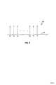
図3に、多重キャリア信号伝送を示すグラフ100を示す。グラフ100の水平軸102は周波数を表しており、軸102の左側に向かう方向に周波数が低くなり、軸102の右側に向かう方向に周波数が高くなる。グラフ100は、J個の個別のキャリア信号を取り込んだ多重キャリア信号が、周波数f1、f2、...fjの周波数でキャリアによって伝送されることを示している。FIG. 3 shows a
グラフ100に示す各キャリアは、所定数の情報ビットを送信することができる。従って、多重キャリア信号によって伝送される総ビット数は、各キャリアが伝送することができるビット数の和である。例えば、各キャリアが3ビットの情報を伝送することができる場合は、グラフ100に示す信号は、全部でJ*3ビットの情報を送信することができる。 Each carrier shown in the
好適な実施態様では、各キャリアは、直交振幅変調(QAM)を使用して情報を伝送する。QAMは、各キャリア信号の振幅と位相の異なる組み合わせが、異なるディジタル値を表すところの従来のディジタル信号符号化技法である。例えば、キャリアが4つの可能な値のうちの1つを表すことができるように、2つの異なる可能な振幅(A1とA2)、及び、2つの異なる可能な位相(P1とP2)を使用して、キャリア信号を符号化することができる。ここで、第1の値は、キャリア信号の振幅がA1で位相がP1の場合であり、第2の値は、A1とP2の組み合わせに対応し、第3の値は、A2とP1の組み合わせに対応し、そして、第4の値は、A2とP2の組み合わせに対応する。所定のキャリア信号についての振幅と位相の種々の組み合わせは、「群(constellation)」と呼ばれる。特定のキャリアによって伝送されうる総ビット数は、該キャリアについて取りうる最大の群サイズの関数であるということに留意されたい。 In the preferred embodiment, each carrier transmits information using quadrature amplitude modulation (QAM). QAM is a conventional digital signal encoding technique in which different combinations of amplitude and phase of each carrier signal represent different digital values. For example, using two different possible amplitudes (A1 and A2) and two different possible phases (P1 and P2) so that the carrier can represent one of four possible values. Thus, the carrier signal can be encoded. Here, the first value is the case where the amplitude of the carrier signal is A1 and the phase is P1, the second value corresponds to the combination of A1 and P2, and the third value is the combination of A2 and P1. And the fourth value corresponds to the combination of A2 and P2. The various combinations of amplitude and phase for a given carrier signal are called “constellations”. Note that the total number of bits that can be transmitted by a particular carrier is a function of the largest group size that can be taken for that carrier.
各キャリアについて、最大の群サイズ、すなわち、該キャリアが伝送することができる最大のビット数は、通信チャンネルの信号対ノイズ比(SNR)の関数であり、また、所望のビット誤り率(BER)の関数である。BERは、伝送された総ビット数当たりの1ビット送信/受信誤り(エラー)の数である。特定のキャリアに関連する個別の振幅及び/または位相の数が増えると(すなわち、群サイズが増えると)、ビット誤りの可能性が高まる。BERは、群サイズが大きくなると増加する。なぜなら、個別の振幅及び/または位相の数が増えると、個別の位相及び/または振幅間の差が小さくなり、従って、異なる位相及び/または振幅値を識別する受信機の能力が減少するからである。 For each carrier, the maximum group size, ie, the maximum number of bits that the carrier can transmit, is a function of the signal to noise ratio (SNR) of the communication channel and the desired bit error rate (BER). Is a function of BER is the number of 1-bit transmission / reception errors (errors) per total number of bits transmitted. As the number of individual amplitudes and / or phases associated with a particular carrier increases (ie, the group size increases), the likelihood of bit errors increases. The BER increases as the group size increases. This is because as the number of individual amplitudes and / or phases increases, the difference between the individual phases and / or amplitudes decreases, thus reducing the receiver's ability to identify different phases and / or amplitude values. is there.
BERとSNRの関係は、多重キャリア通信の分野では周知である。所定の群サイズに対して一定値以下のBERをサポートすることが可能な最小のSNRを示すテーブルを利用することができる。例えば、以下のテーブルでは、群信号対ノイズ比SNR[cj]は、BERの期待値10−7(すなわち、毎107ビット送信当たり1ビットのエラー)を得るために、指定されたサイズを有する群を送信するために必要な最小のSNRを示す。群サイズが大きくなると、必要な最小のSNRもまた増加するということに留意されたい。The relationship between BER and SNR is well known in the field of multicarrier communication. A table indicating the minimum SNR capable of supporting a BER of a certain value or less for a predetermined group size can be used. For example, in the table below, the group signal-to-noise ratio SNR [cj ] is the specified size to obtain the expected BER of 10−7 (ie, 1 bit error per 107 bits transmission). It shows the minimum SNR required to transmit a group with. Note that as the group size increases, the minimum required SNR also increases.
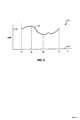
図4のグラフ110は、周波数f1とfj間のキャリアを有する多重キャリア信号を送信する通信チャンネルについてのSNRと周波数の関係を示す。グラフ110の垂直軸112がSNRを表す。グラフ110の水平軸114は、図3のグラフ100の水平軸102に関して示したのと同様に周波数を表す。A
曲線116は、f1とfjの間の周波数についてSNRと周波数の関係を示す。ここで、f1とfjはそれぞれ、多重キャリア周波数信号の最低、最高キャリア周波数である。曲線116は、例えば、周波数fmにおけるSNRが、周波数fnにおけるSNRよりも小さくなるように、周波数に応じてSNRが変化することを示している。上記のテーブルによれば、所定のBERに対して、キャリア周波数fmによってサポートされる群サイズが、キャリア周波数fnによってサポートされる群サイズよりも小さいと推定される。
図5のグラフ120は、曲線122を使用してSNRと周波数の仮想的な関係を示すものである。グラフ120は、図4のグラフ110に類似している。グラフ120の垂直軸はSNRを表しており、10−7のBERについての群サイズに対する最小のSNR要件を示した上記テーブルのSNR値が重ね書きされている。グラフ120は、2ビットの群サイズをサポートするために14dBのSNRが必要であり、3、4、及び5ビットの群サイズをサポートするために19、21、及び24dBのSNRがそれぞれ必要であることを示している。これに基づけば、曲線122を使用してf1とfj間の各キャリア周波数について最大の群サイズを決定することが可能である。例えば、曲線122は、f1とfa間の任意のキャリア周波数は、4ビットの最大群サイズをサポートすることができるということを示している。なぜなら、f1とfa間の曲線122のすべての部分は、21dB(4ビットの群サイズをサポートするために必要な最小のSNR)より大きいが、24dB(5ビットに対する最小のSNR)よりは小さいからである。f1とfa間のどのキャリア周波数も、最小のSNR要件を生成するために使用される該BERにおいて5ビットの群サイズをサポートすることはできない。A graph 120 in FIG. 5 shows a virtual relationship between SNR and frequency using a
図5において、faとfb間の曲線122の部分は24dBより大きい。従って、faとfb間のキャリア周波数は、少なくとも5ビットの最大群サイズをサポートすることができる。同様に、fbとfc間のキャリア周波数は、4ビットの最大群サイズをサポートし、fcとfd間のキャリア周波数は、3ビットの最大群サイズをサポートし、fdとfe間のキャリア周波数は、2ビットの最大群サイズをサポートし、feとfj間のキャリア周波数は、3ビットの最大群サイズをサポートする。5, the portion of the
必要な最小SNRと実際の送信チャンネルのSNRとの差は、「マージン」と呼ばれる。例えば、曲線122は、4ビットがキャリア周波数f1で使用される場合は、f1のキャリア周波数は0より幾分大きなマージン124を有するということを示している。なぜなら、図5に示すf1におけるSNRは、最小SNR要件21dBよりも大きいからである。同様にして、特定のキャリア周波数においてサポートされる最大群サイズよりも小さいものを使用することができる。例えば、曲線122は、周波数faのキャリアが5ビットの群サイズをサポートするということを示している(faにおけるSNRが24dBなので)が、3ビットだけで周波数faのキャリアを符号化することができる。この場合は、周波数faにおけるマージンは、faおける送信チャンネルのSNR(24dB)と周波数faにおいて3ビットの群サイズをサポートするために必要なSNR(19dB)との差である。従って、周波数faにおけるマージンは5dBである。The difference between the required minimum SNR and the actual transmission channel SNR is called the “margin”. For example,
多重キャリア信号が、最大のデータビット数を伝送するために使用される場合は、通信チャンネルのSNRが最初に測定され、次に、各キャリアが、サポートされる最大群サイズに設定される。しかし、多くの用途において、多重キャリア信号は、可能な最大のビット数よりも少ないビット数を送信するために使用される。そのような場合には、信号の全体のマージンを最大にし、これによって誤り率を低減することが有効である。このことは、簡単な例で説明することができる。 If a multi-carrier signal is used to transmit the maximum number of data bits, the SNR of the communication channel is measured first and then each carrier is set to the maximum group size supported. However, in many applications, multicarrier signals are used to transmit fewer bits than the maximum possible number of bits. In such a case, it is effective to maximize the overall margin of the signal and thereby reduce the error rate. This can be illustrated with a simple example.
2チャンネルの多重キャリア信号が、第1のキャリアについては5ビットの、第2のキャリアについては4ビットの最大群サイズを有していると仮定する。さらに、該信号を使用して6ビットを送信することが望まれていると想定する。2つキャリア間にビットを割り当てるための1つの方法は、第1のキャリアを使用して5ビットを送信し、第2のキャリアを使用して1ビットを送信することである。しかし、この場合は、第1のキャリアに対するマージンは比較的小さく、第2のキャリアに対するマージンは比較的大きい。第1のキャリアによって伝送されるビットには、第2のキャリアによって伝送されるビットよりも多くのエラーが発生するであろう。なぜなら、大部分のビットは第1のキャリアによって送信されるからである。この場合、信号の全体の誤り率は目標BERより低いものの、依然として、この場合にあるべき値より大きい。ビットを割り当てるより有効な方法は、3つのビットを2つのキャリアのそれぞれに割り当てることであろう。この場合は、両方のキャリアが比較的大きなマージンで動作し、信号の全体の誤り率は減少する。 Assume that a two-channel multi-carrier signal has a maximum group size of 5 bits for the first carrier and 4 bits for the second carrier. Further assume that it is desired to transmit 6 bits using the signal. One way to allocate bits between two carriers is to send 5 bits using the first carrier and 1 bit using the second carrier. However, in this case, the margin for the first carrier is relatively small and the margin for the second carrier is relatively large. There will be more errors in the bits transmitted by the first carrier than in the bits transmitted by the second carrier. This is because most of the bits are transmitted on the first carrier. In this case, the overall error rate of the signal is lower than the target BER, but is still higher than it should be in this case. A more effective way of assigning bits would be to assign three bits to each of the two carriers. In this case, both carriers operate with a relatively large margin and the overall error rate of the signal is reduced.
もちろん、多くの多重キャリア通信アプリケーションでは、数百ものキャリア及び数百から数千ものビットが伝送される。さらに、比較的高速な方法でビットを割り当てることが必要である。なぜなら、時間を費やして割り当てるビットは、時間を費やさない通信情報だからである。さらに、チャンネルの伝送特性が動的に変化する場合は、ビットを通信中に再割り当てすることが必要となることがある。 Of course, in many multi-carrier communication applications, hundreds of carriers and hundreds to thousands of bits are transmitted. Furthermore, it is necessary to allocate bits in a relatively fast manner. This is because the bits allocated by spending time are communication information that does not spend time. Further, if the channel transmission characteristics change dynamically, it may be necessary to reassign bits during communication.
図6のフローチャート150は、多重キャリア信号のキャリア間にビットを割り当てるための技法を示すものである。処理はステップ152で開始し、そこで、ビットを割り当てるために使用される種々の量が初期化される。これらの量には、マージンの上限MH、マージンの下限ML、及び、反復カウンタkが含まれ、これについてはさらに詳しく後述する。ステップ152の次にステップ154に進み、そこで、マージンMが、MHとMLを平均することによって計算される。
ステップ154の次はステップ156に進み、そこで、種々の群サイズRSNR[c]に対してテーブルが指示する必要なSNRが計算される。RSNR[c]は、マージンMとサイズcの群をサポートすることができる最小のSNR要件との和に等しいエントリを有するテーブルであり、従って、拡張された群信号対ノイズ比SNRa[cj]=SNR[cj]+Mから構成される。ステップ156の次はステップ158に進み、ここで、ビットテーブルB[j]が計算される。B[j]は、RSNR[c]に記憶される値が与えられた場合に、各キャリアf1、...fJに割り当てることができるビットの最大数のテーブルである。最大数のビットは、図5に関して上述したのと同様にして、各キャリアに割り当てられる。Following the
ステップ158の次にステップ160に進み、そこで、値Nmaxが計算される。Nmaxは、チャンネル上を伝送することができるビットの最大数を表しており、テーブルB[j]内のすべての値を合計することによって決定される。テーブルB[j]は、計算されたマージンを加えた各群サイズに対して要求される最小のSNRに基づいて、各キャリアについて送信することができるビットの最大数を含んでいるので、Nmaxは、各キャリアが少なくともMのマージンを有するチャンネル上を送信可能なビットの最大数を表す。Step 158 is followed by
ステップ160の次は検査ステップ162に進む。ステップ162では、Nmaxが、多重キャリア信号を使用して送信されるビット数であるNに等しいかどうかを判定する。Nmaxが実際にNに等しくない場合は、処理は終了し、ビットテーブルB[j]は、各キャリアが少なくともMと同じ大きさのマージンを有するところの多重キャリア信号のキャリア間のビット割り当てを表す。Following
検査ステップ162でNmaxがNに等しくないと判定された場合は、処理は、検査ステップ162から検査ステップ164に移行する。NがNmaxより小さい場合は、次の繰り返しで(Nmaxを減少させるために)マージンを増やすことができるということに留意されたい。同様にして、NがNmaxよりも小さくない場合は、マージンは大き過ぎ、次の繰り返しで小さくすることが必要である。検査ステップ164で、NがNmaxより小さいと判定された場合は、制御は、検査ステップ164からステップ166に移り、そこで、マージンの下限MLがMに等しく設定される。MLをMに等しく設定することによりMLが効果的に増加し、ステップ154における次の繰り返しで計算されるマージンMの値が増加することになる。If it is determined in the
逆に、ステップ164で、Nが、Nmaxより小さくないと判定された場合は、制御は、ステップ164からステップ168に移り、そこで、マージンの上限MHがMに等しく設定される。これによって、MHの値が効果的に減少し、従って、Mが次の繰り返しのステップ154で計算されるときにMの値が減少することになる。Conversely, if it is determined in
制御は、ステップ166またはステップ168のいずれかからステップ170に移り、そこで、反復カウンタkが増加される。ステップ170の次は検査ステップ172に進み、そこで、反復カウンタが、反復カウンタに対する許容可能な最大値Kmaxより小さいかどうかが判定される。反復カウンタkは、ステップ162における終了条件(すなわち、Nmax=N)が満たされない場合でも、所定の繰り返し数の後に確実にアルゴリズムを終了させるために使用される。好適な実施態様では、Kmaxは16である。Control transfers from either step 166 or step 168 to step 170 where the iteration counter k is incremented. Following the
検査ステップ172でkがKmaxより小さくないと判定された場合には、制御は、ステップ172からステップ174に移り、そこで、適宜、残りのビットが削除されるか、またはビットテーブルB[j]に追加される。テーブルB[j]に割り当てられたすべてのビットの和が、多重チャンネル信号によって伝送されるビット数Nに等しくなるように、ビットは、ステップ174でランダム方式または疑似ランダム方式で追加または削除される。この例の場合は、各キャリアが少なくともMのマージンを有するという保証はない。ステップ174は、アルゴリズムがステップ162において終了条件を満足することができなかった場合に、割り当てプロセスを終了させるために単に実行される。If
検査ステップ172で、反復カウンタkが、予め設定した反復カウンタの最大値より小さいと判定された場合は、制御は、ステップ172から検査ステップ176に移り、そこで、アルゴリズムが発散するかどうか、すなわち、(Nmax−N)が増加するかどうかが判定される。アルゴリズムは、検査ステップ162でNmaxがNに等しいときに終了するので、各繰り返しでNmaxの値がNの値に近づくように、アルゴリズムは収斂するのが望ましい。しかし、検査ステップ176で、Nmaxの値が、各繰り返しでNの値から実際に遠ざかるということが判定された場合は、制御は、ステップ176からステップ174に移り、そこで、上述したように、残りのビットが、テーブルB[j]の値中にランダムに分配され、その後、処理は終了する。If in
検査ステップ176で、アルゴリズムは発散しないということが判定された場合は、制御は、ステップ176からステップ154に戻り、そこで、マージンが次の繰り返しのために計算される。次の繰り返し154で計算されるマージンは、上述したように、検査ステップ164でNがNmaxより小さかったかそうでなかったに応じて、前の繰り返しで計算されたマージンより小さいか大きいかのいずれかである。If
図7のフローチャート180は、図6に示したフローチャート150のステップ152の初期化ルーチンを詳細に示すものである。初期化ルーチンに入ると、処理がステップ182で開始し、そこで、チャンネルの伝送特性が測定されて、多重キャリア信号の各キャリア周波数における信号対ノイズ比が決定される。図4及び図5に関して上述したように、伝送チャンネルの信号対ノイズ比は、周波数の関数でありうる。ステップ182でチャンネルの伝送特性を測定するが、それについては詳細に後述する。 A
ステップ182の次にステップ184に進み、そこで、要求される最小の信号対ノイズ比のテーブルSNR[c]が初期化される。上述したように、所定のビット誤り率(BER)について、各群サイズcに対して要求される最小のSNRを、当該技術分野において既知の従来の計算によって、あるいは、テキストブックの値を参照することによって決定することができる。ステップ184の次はステップ186に進み、そこで、ビットテーブルB[j]が計算される。ステップ186でのビットテーブルの計算は、拡張されていないSNRテーブルが、ステップ158で使用されるRSNRテーブルではなくてステップ186で使用されるSNR[cj]であるという点を除いて、図6のフローチャート150に関して上述したステップ158におけるビットテーブルの計算に類似している。ステップ186でSNRテーブルを使用することにより、ビットテーブルB[j]をマージン0で効率的に計算することができる。ステップ186の次はステップ188に進み、そこで、Nmaxが計算される。ステップ188は、図6のフローチャート150に関して上述したステップ160に類似している。すなわち、Nmaxは、ビットテーブルB[j]内のすべてのエントリの単純な和である。Step 182 is followed by
ステップ188の次はステップ190に進み、そこで、NmaxがNに等しいかどうかが判定される。ステップ190でNmaxがNに等しい場合は、処理は、全アルゴリズム(初期化部分だけではない)について完了する。なぜなら、チャンネルはNmaxビットの伝送だけをサポートするからである。すなわち、デフォルトでは、チャンネルはNビットまでしか送信することができないので、ステップ190でNmaxがNに等しい場合は、アルゴリズムを継続し、マージンを計算するポイントはない。Following the
検査ステップ190で、NmaxがNに等しくないと判定された場合は、制御は、ステップ190から検査ステップ192に移り、そこで、NがNmaxより小さいかどうかが判定される。ステップ192でNがNmaxより小さくない場合は、チャンネルは、ステップ184でSNRテーブルを構成するために使用されるBERでのNビットの送信をサポートしないということに留意されたい。すなわち、チャンネルの帯域幅はあまりにも小さい。しかし、この場合は、アルゴリズムは、負のマージンを計算し、負のマージンを最大にするために単に処理を続行することによって継続可能であり、これによって、実現されるBERは所望のBERを越えるであろうが、与えられた要求データレートに対して、それはさらに最小化される。他の実施態様では、アルゴリズムはこの時点で終了することができ、ビットを割り当てることはできないということを示す。さらに他の実施態様では、アルゴリズムは、種々の群サイズに対して、より大きなBER及び(可能性のある)より小さなSNR要件を使用して再実行することができる。If in
ステップ192で、NがNmaxよりも小さくない(すなわち、システムが負のマージンで動作している)と判定された場合は、制御は、ステップ192からステップ198に移り、そこで、マージンの下限MLが0に設定される。ステップ198の次はステップ200に進み、そこで、マージンの上限が、式MH=(10/J)*(Nmax−N)を使用して設定される。しかし、この場合は、Nmax−Nが正の数であるので、マージンの上限は、ステップ200で正の値に設定されることになるということに留意されたい。If it is determined in
ステップ200またはステップ196のいずれかに続いて、制御はステップ202に移り、そこで、所定数の繰り返しの後にアルゴリズムを終了させるために使用される反復カウンタが1に設定される。ステップ202に続いて、初期化ルーチンが起動されて、図6に関して上述したように、残りの処理を続行することができるようになる。 Following either step 200 or step 196, control passes to step 202 where the iteration counter used to terminate the algorithm after a predetermined number of iterations is set to one. Following
ステップ196でMLを設定するために、及び、ステップ200でMHを設定するために使用される式は、最終的なマージンがMLとMHの間の範囲外に出ないことを保証しつつ、アルゴリズムが適度な繰り返し数で収斂するように、マージンの上限及び下限を与える。もちろん、MLとMHの初期値を計算するための他の式または技法を使用して本発明を実施することが可能である。 The equations used to set ML at
図8のフローチャート210は、多重キャリア信号のそれぞれのキャリアにビットを割り当てて、ビットアロケーションテーブルの変化を送信機と同期させるために受信機によって使用されるソフトウエアの動作を示すものである。最初の検査ステップ262で処理が開始するが、そこで、受信機が基準フレームを受信したかどうかを判定する。基準フレームは、前もって決められており、受信機がチャンネルの特性を決定することができるように送信機によって受信機に供給される特別なデータビットからなる検出可能なフレームである。基準フレームを送信機によって送るべきかどうかを判定するために他の従来技法を使用することができるが、好適な実施態様では、基準フレームを周期的に送信する。基準フレームは、基準フレームが供給されつつあるということを示すパケット内の特別なヘッダーのような、種々の従来技法のうちの任意の1つを使用して、受信機により認識される。多重キャリア通信に関連して基準フレームを使用することは、当該技術分野では周知である。基準フレームがステップ262で受信されない場合は、ソフトウエアは検査ステップ262にループバックして、基準フレームを受信したがどうかについてポーリングする。
検査ステップ262で、基準フレームを受信したことが判定された場合は、制御は、ステップ262からステップ264に移り、そこで、基準フレーム内のエラーが第1の信号の既知の群距離(constellation distance)に関して測定される。基準フレームは、前もって決められた信号なので、受信機は送信機によって何が送信されたかを正確に知ることができるということに留意されたい。従って、受信機によって受信されたデータと、信号データの期待値との差は、伝送チャンネルによって導入されるエラーによって説明することができる。これらのエラーはステップ264で測定される。 If the
ステップ264に続いてステップ266に進み、そこで、受信機は、ステップ264で測定したエラーに基づいてチャンネルの特性を決定する。これは、検出された伝送エラーに基づいてチャンネルの特性を決定するための技法を使用する従来方式で行われる。ステップ266に続いてステップ268に進み、そこで、受信機は、好適な実施態様おいては、図6及び図7に関連して開示した技法を使用してキャリア間に種々のビットを割り当てる。 Following the
ステップ268に続いて検査ステップ270に進み、そこで、ステップ268で与えられたビットアロケーションテーブルが、以前のビットアロケーションテーブルと異なるかどうかを判定する。すなわち、ステップ270で、新たに計算されたビットアロケーションテーブルと、以前のビットアロケーションテーブルとの間の差違があるかどうかが判定される。検査ステップ270で、差違がない(すなわち、ビットアロケーションテーブルは変化していない)ということが判定された場合は、制御は、ステップ270からステップ262に戻り、そこで、ソフトウエアは、送信機が別の基準フレームを送信するのを待つ。そうでなくて、ステップ270で、新しいビットアロケーションテーブルテーブルが、以前のビットアロケーションテーブルと異なるということが判定された場合は、制御は、ステップ270からステップ272に移り、そこで、ビットアロケーションテーブルが変化したことを示すフラグが、受信機から送信機に送られる。好適な実施態様では、フラグは、フラグ用だけに使用するために送信機及び受信機によって予約された多重キャリア信号のうちの1つのキャリアによって、ステップ272で送信される。他の実施態様では、予約されたキャリアを使用して、新しいビットアロケーションテーブルを送信することもできる。 Following
ステップ272に続いてステップ274に進み、そこで、受信機は、ステップ268で決定された新しいビットアロケーションテーブルを送信機に送信する。制御は、ステップ274の後に検査ステップ262に戻り、送信機が、他の基準フレームを送信したかどうかをポーリングするとともに、それを待つ。 Following
図示し、詳細に説明した好適な実施態様に関連して本発明を開示したが、当業者には、それについて種々の修正及び改良が可能であることが容易に理解されるであろう。従って、本発明の思想及び範囲は、請求の範囲によってのみ制限されるべきものである。 Although the present invention has been disclosed in connection with the preferred embodiments shown and described in detail, those skilled in the art will readily appreciate that various modifications and improvements can be made thereto. Accordingly, the spirit and scope of the present invention should be limited only by the scope of the claims.
Claims (3)
Translated fromJapanese送信機と受信機との間の通信中に用いる複数のサブチャネルに対するビットの割り当てを定める第1のビットアロケーションテーブルおよび第2のビットアロケーションテーブルと、
前記第1および第2のビットアロケーションテーブルに結合され、前記複数のサブチャネルの複数の特徴のうちの少なくとも一つの、少なくとも一部の変化に基づいて、前記第1および第2のビットアロケーションテーブルのいずれか一つを選択するよう構成されたテーブルスイッチユニットであって、前記複数の特徴は通信中に計測されるテーブルスイッチユニットと、
を備えた送信機。A transmitter in a multi-carrier modulation system,
A first bit allocation table and a second bit allocation table that define bit assignments for a plurality of subchannels used during communication between a transmitter and a receiver;
Coupled to the first and second bit allocation tables, and based on at least some changes in at least one of the plurality of features of the plurality of subchannels, the first and second bit allocation tables A table switch unit configured to select any one of theplurality of characteristics, the table switch unit being measured during communication,
With transmitter.
前記複数のサブチャネルの複数の特徴のうちの少なくとも一つの、少なくとも一部の変化は、少なくとも一つのコントロールフレームおよび一つのデータフレームを含むスーパーフレームを用いて決定されることを特徴とする送信機。The transmitter of claim 1, wherein
At least one change of at least one of the plurality of characteristics of the plurality of subchannels is determined using a superframe including at least one control frame and one data frame. .
前記テーブルスイッチユニットは、前記第1および第2のビットアロケーションテーブルのうちの少なくとも一つについての、前記受信機のテーブルコントロールユニットからの更新を、スーパーフレームに基づいて受信するよう構成されていることを特徴とする送信機。The transmitter of claim 2, wherein
The table switch unit is configured to receive an update from a table control unit of the receiver for at least one of the first and second bit allocation tables based on a superframe. Transmitter characterized by.
Applications Claiming Priority (1)
| Application Number | Priority Date | Filing Date | Title |
|---|---|---|---|
| US08/873,421US6072779A (en) | 1997-06-12 | 1997-06-12 | Adaptive allocation for variable bandwidth multicarrier communication |
Related Parent Applications (1)
| Application Number | Title | Priority Date | Filing Date |
|---|---|---|---|
| JP50305399ADivisionJP2002504283A (en) | 1997-06-12 | 1998-06-09 | Adaptive bit allocation for variable band multi-carrier communication |
Related Child Applications (1)
| Application Number | Title | Priority Date | Filing Date |
|---|---|---|---|
| JP2009224722ADivisionJP2010035194A (en) | 1997-06-12 | 2009-09-29 | Adaptive bit allocation for variable bandwidth multi-carrier communication |
Publications (2)
| Publication Number | Publication Date |
|---|---|
| JP2007129754A JP2007129754A (en) | 2007-05-24 |
| JP4431133B2true JP4431133B2 (en) | 2010-03-10 |
Family
ID=25361602
Family Applications (6)
| Application Number | Title | Priority Date | Filing Date |
|---|---|---|---|
| JP50305399APendingJP2002504283A (en) | 1997-06-12 | 1998-06-09 | Adaptive bit allocation for variable band multi-carrier communication |
| JP2006341428AExpired - LifetimeJP4431133B2 (en) | 1997-06-12 | 2006-12-19 | Adaptive bit allocation for variable-band multicarrier communications. |
| JP2006341416APendingJP2007129753A (en) | 1997-06-12 | 2006-12-19 | Adaptive bit allocation for variable bandwidth multicarrier communication |
| JP2009224722APendingJP2010035194A (en) | 1997-06-12 | 2009-09-29 | Adaptive bit allocation for variable bandwidth multi-carrier communication |
| JP2010031366AExpired - LifetimeJP5132697B2 (en) | 1997-06-12 | 2010-02-16 | Adaptive bit allocation for variable-band multicarrier communications. |
| JP2012121351AExpired - LifetimeJP5525008B2 (en) | 1997-06-12 | 2012-05-28 | Adaptive bit allocation method, multi-carrier transmission system, and apparatus for variable-band multi-carrier communication |
Family Applications Before (1)
| Application Number | Title | Priority Date | Filing Date |
|---|---|---|---|
| JP50305399APendingJP2002504283A (en) | 1997-06-12 | 1998-06-09 | Adaptive bit allocation for variable band multi-carrier communication |
Family Applications After (4)
| Application Number | Title | Priority Date | Filing Date |
|---|---|---|---|
| JP2006341416APendingJP2007129753A (en) | 1997-06-12 | 2006-12-19 | Adaptive bit allocation for variable bandwidth multicarrier communication |
| JP2009224722APendingJP2010035194A (en) | 1997-06-12 | 2009-09-29 | Adaptive bit allocation for variable bandwidth multi-carrier communication |
| JP2010031366AExpired - LifetimeJP5132697B2 (en) | 1997-06-12 | 2010-02-16 | Adaptive bit allocation for variable-band multicarrier communications. |
| JP2012121351AExpired - LifetimeJP5525008B2 (en) | 1997-06-12 | 2012-05-28 | Adaptive bit allocation method, multi-carrier transmission system, and apparatus for variable-band multi-carrier communication |
Country Status (6)
| Country | Link |
|---|---|
| US (1) | US6072779A (en) |
| EP (3) | EP1940103B1 (en) |
| JP (6) | JP2002504283A (en) |
| AU (1) | AU740221B2 (en) |
| CA (1) | CA2293239C (en) |
| WO (1) | WO1998057472A1 (en) |
Cited By (1)
| Publication number | Priority date | Publication date | Assignee | Title |
|---|---|---|---|---|
| JP2010154550A (en)* | 1997-06-12 | 2010-07-08 | Daphimo Co Bv Llc | Adaptive bit allocation for variable bandwidth multicarrier communication |
Families Citing this family (96)
| Publication number | Priority date | Publication date | Assignee | Title |
|---|---|---|---|---|
| US6798735B1 (en) | 1996-06-12 | 2004-09-28 | Aware, Inc. | Adaptive allocation for variable bandwidth multicarrier communication |
| US6865232B1 (en)* | 1996-09-02 | 2005-03-08 | Stmicroelectronics N.V. | Multi-carrier transmission systems |
| US6130882A (en)* | 1997-09-25 | 2000-10-10 | Motorola, Inc. | Method and apparatus for configuring a communication system |
| WO1999020027A2 (en)* | 1997-10-10 | 1999-04-22 | Aware, Inc. | Splitterless multicarrier modem |
| US20030026282A1 (en)* | 1998-01-16 | 2003-02-06 | Aware, Inc. | Splitterless multicarrier modem |
| ATE450108T1 (en) | 1997-10-10 | 2009-12-15 | Daphimo Co B V Llc | PARTLESS MULTI CARRIER MODEM |
| US7248626B2 (en)* | 1997-12-05 | 2007-07-24 | Paradyne Corporation | System and method of communication via embedded modulation |
| US9432172B2 (en) | 1997-12-05 | 2016-08-30 | Rembrandt Wireless Technologies, Lp | System and method of communication using at least two modulation methods |
| US6075821A (en)* | 1997-12-16 | 2000-06-13 | Integrated Telecom Express | Method of configuring and dynamically adapting data and energy parameters in a multi-channel communications system |
| US6094459A (en)* | 1997-12-16 | 2000-07-25 | Integrated Telecom Express | Circuit for configuring data and energy parameters in a multi-channel communications system |
| US6084917A (en) | 1997-12-16 | 2000-07-04 | Integrated Telecom Express | Circuit for configuring and dynamically adapting data and energy parameters in a multi-channel communications system |
| US6128348A (en)* | 1997-12-16 | 2000-10-03 | Integrated Telecom Express | Method for configuring data and energy parameters in a multi-channel communications system |
| US6084906A (en)* | 1997-12-17 | 2000-07-04 | Integrated Telecom Express | ADSL transceiver implemented with associated bit and energy loading integrated circuit |
| US6088387A (en) | 1997-12-31 | 2000-07-11 | At&T Corp. | Multi-channel parallel/serial concatenated convolutional codes and trellis coded modulation encoder/decoder |
| JP3082756B2 (en) | 1998-02-27 | 2000-08-28 | 日本電気株式会社 | Multi-carrier transmission system and method |
| JP3186693B2 (en)* | 1998-04-24 | 2001-07-11 | 三菱電機株式会社 | Data communication device |
| ES2709692T3 (en)* | 1998-06-26 | 2019-04-17 | Tq Delta Llc | Communication through multiple carriers with variable airspeed |
| US6480510B1 (en) | 1998-07-28 | 2002-11-12 | Serconet Ltd. | Local area network of serial intelligent cells |
| DE19845796C2 (en)* | 1998-09-21 | 2002-01-17 | Mannesmann Ag | Channel assignment of a channel for data calls with a different useful / interference signal (N / S) ratio than for channels for voice calls in mobile radio networks |
| US6310909B1 (en)* | 1998-12-23 | 2001-10-30 | Broadcom Corporation | DSL rate adaptation |
| US7133441B1 (en) | 1999-02-23 | 2006-11-07 | Actelis Networks Inc. | High speed access system over copper cable plant |
| US20040044942A1 (en)* | 1999-03-12 | 2004-03-04 | Aware, Inc. | Method for seamlessly changing power modes in an ADSL system |
| US6567473B1 (en) | 1999-03-12 | 2003-05-20 | Aware, Inc. | Method for seamlessly changing power modes in a ADSL system |
| US6778596B1 (en)* | 1999-03-12 | 2004-08-17 | Aware, Inc. | Method and multi-carrier transceiver with stored application profiles for supporting multiple applications |
| US20060274840A1 (en)* | 2005-06-06 | 2006-12-07 | Marcos Tzannes | Method for seamlessly changing power modes in an ADSL system |
| US7952511B1 (en) | 1999-04-07 | 2011-05-31 | Geer James L | Method and apparatus for the detection of objects using electromagnetic wave attenuation patterns |
| US6956826B1 (en) | 1999-07-07 | 2005-10-18 | Serconet Ltd. | Local area network for distributing data communication, sensing and control signals |
| US6748016B1 (en) | 1999-07-16 | 2004-06-08 | Aware, Inc. | System and method for transmitting messages between transceivers using electromagnetically coupled signals |
| US6690677B1 (en) | 1999-07-20 | 2004-02-10 | Serconet Ltd. | Network for telephony and data communication |
| WO2001015403A1 (en)* | 1999-08-23 | 2001-03-01 | Legerity, Inc. | Bit allocation method for a discrete multitone (dmt) system |
| CA2382519C (en)* | 1999-09-15 | 2009-01-27 | Aware Inc. | Multicarrier system with stored application profiles for supporting multiple applications |
| CA2788662C (en) | 2000-01-07 | 2017-01-03 | Aware, Inc. | Diagnostic methods and systems for multicarrier modems |
| AU2001247249A1 (en)* | 2000-02-29 | 2001-09-12 | Inari, Inc. | High data-rate powerline network system and method |
| US6549616B1 (en) | 2000-03-20 | 2003-04-15 | Serconet Ltd. | Telephone outlet for implementing a local area network over telephone lines and a local area network using such outlets |
| JP2004501535A (en) | 2000-04-18 | 2004-01-15 | アウェア, インコーポレイテッド | Multicarrier modulation system and method using variation margin |
| IL135744A (en) | 2000-04-18 | 2008-08-07 | Mosaid Technologies Inc | Telephone communication system over a single telephone line |
| US6842459B1 (en) | 2000-04-19 | 2005-01-11 | Serconet Ltd. | Network combining wired and non-wired segments |
| AU2001257133A1 (en) | 2000-04-22 | 2001-11-07 | Atheros Communications, Inc. | Multi-carrier communication systems employing variable symbol rates and number of carriers |
| JP2001358692A (en) | 2000-06-14 | 2001-12-26 | Nec Corp | Orthogonal frequency-division multiplex modulating and demodulating circuit |
| US20020034220A1 (en)* | 2000-09-21 | 2002-03-21 | Tom Duxbury | Apparatus and method for digital subscriber line signal communications |
| US7103096B2 (en) | 2000-10-12 | 2006-09-05 | 3Com Corporation | Performance evaluation of multicarrier channels with forward error correction and automatic retransmission request |
| US6732323B1 (en) | 2000-10-12 | 2004-05-04 | 3Com Corporation | Method of selecting initialization parameters for multi-channel data communication with forward error correction |
| US7110467B2 (en)* | 2000-10-12 | 2006-09-19 | 3Com Corporation | Performance evaluation of a G.dmt-compliant digital subscriber line system |
| US7131038B2 (en)* | 2000-10-12 | 2006-10-31 | 3Com Corporation | Performance evaluation of multicarrier channels |
| EP1346398A2 (en)* | 2000-11-01 | 2003-09-24 | Actelis Networks Ltd. | High speed access system over copper cable plant |
| US6980601B2 (en)* | 2000-11-17 | 2005-12-27 | Broadcom Corporation | Rate adaptation and parameter optimization for multi-band single carrier transmission |
| US6807234B2 (en)* | 2000-12-19 | 2004-10-19 | Intel Corporation | Method and apparatus for constellation mapping and bitloading in multi-carrier transceivers, such as DMT-based DSL transceivers |
| EP1555773B1 (en)* | 2001-01-16 | 2009-09-02 | Daphimo Co. B.V., LLC | Fast initialization using seamless rate adaption |
| US6718493B1 (en) | 2001-05-17 | 2004-04-06 | 3Com Corporation | Method and apparatus for selection of ARQ parameters and estimation of improved communications |
| US7263130B1 (en) | 2001-05-25 | 2007-08-28 | 3Com Corporation | Method and apparatus for evaluating error control parameters of self-similar constellations |
| IL144158A (en) | 2001-07-05 | 2011-06-30 | Mosaid Technologies Inc | Outlet for connecting an analog telephone set to a digital data network carrying voice signals in digital form |
| US20030039317A1 (en)* | 2001-08-21 | 2003-02-27 | Taylor Douglas Hamilton | Method and apparatus for constructing a sub-carrier map |
| US6816988B2 (en)* | 2001-08-31 | 2004-11-09 | Agilent Technologies, Inc. | Method and system for minimal-time bit-error-rate testing |
| US20030097623A1 (en)* | 2001-10-24 | 2003-05-22 | Javad Razavilar | Method and apparatus for performance optimization and adaptive bit loading for wireless modems with convolutional coder, FEC, CRC and ARQ |
| DE10154935A1 (en)* | 2001-11-08 | 2003-05-22 | Siemens Ag | Method and device for optimized xDSL data transmission |
| DE60108772T2 (en)* | 2001-12-21 | 2006-01-12 | Agilent Technologies Inc., A Delaware Corp., Palo Alto | Accelerated bit error rate measurement |
| DE10210741A1 (en)* | 2002-03-12 | 2003-10-16 | Siemens Ag | Multiple use system for copper data transmission line uses telephone transmitting via low-pass filter and PC transmitting via high-pass filter to matching filters and receivers at other end of line |
| KR100456693B1 (en)* | 2002-03-28 | 2004-11-10 | 삼성전자주식회사 | Method for minimizing setupt time by the optimization of bit allocation on multi-canannel communication system |
| JP4078105B2 (en) | 2002-04-08 | 2008-04-23 | シャープ株式会社 | Wireless communication system |
| US8194770B2 (en)* | 2002-08-27 | 2012-06-05 | Qualcomm Incorporated | Coded MIMO systems with selective channel inversion applied per eigenmode |
| US8134976B2 (en) | 2002-10-25 | 2012-03-13 | Qualcomm Incorporated | Channel calibration for a time division duplexed communication system |
| US8208364B2 (en) | 2002-10-25 | 2012-06-26 | Qualcomm Incorporated | MIMO system with multiple spatial multiplexing modes |
| US8218609B2 (en) | 2002-10-25 | 2012-07-10 | Qualcomm Incorporated | Closed-loop rate control for a multi-channel communication system |
| US8570988B2 (en) | 2002-10-25 | 2013-10-29 | Qualcomm Incorporated | Channel calibration for a time division duplexed communication system |
| US7002900B2 (en) | 2002-10-25 | 2006-02-21 | Qualcomm Incorporated | Transmit diversity processing for a multi-antenna communication system |
| US8170513B2 (en) | 2002-10-25 | 2012-05-01 | Qualcomm Incorporated | Data detection and demodulation for wireless communication systems |
| US8169944B2 (en) | 2002-10-25 | 2012-05-01 | Qualcomm Incorporated | Random access for wireless multiple-access communication systems |
| US7324429B2 (en) | 2002-10-25 | 2008-01-29 | Qualcomm, Incorporated | Multi-mode terminal in a wireless MIMO system |
| US8320301B2 (en) | 2002-10-25 | 2012-11-27 | Qualcomm Incorporated | MIMO WLAN system |
| US7986742B2 (en) | 2002-10-25 | 2011-07-26 | Qualcomm Incorporated | Pilots for MIMO communication system |
| US20040081131A1 (en) | 2002-10-25 | 2004-04-29 | Walton Jay Rod | OFDM communication system with multiple OFDM symbol sizes |
| IL152824A (en) | 2002-11-13 | 2012-05-31 | Mosaid Technologies Inc | Addressable outlet and a network using same |
| IL154234A (en) | 2003-01-30 | 2010-12-30 | Mosaid Technologies Inc | Method and system for providing dc power on local telephone lines |
| IL154921A (en) | 2003-03-13 | 2011-02-28 | Mosaid Technologies Inc | Telephone system having multiple distinct sources and accessories therefor |
| IL157787A (en) | 2003-09-07 | 2010-12-30 | Mosaid Technologies Inc | Modular outlet for data communications network |
| US7321614B2 (en)* | 2003-08-08 | 2008-01-22 | Intel Corporation | Apparatus and methods for communicating using symbol-modulated subcarriers |
| US8824582B2 (en) | 2003-08-08 | 2014-09-02 | Intel Corporation | Base station and method for channel coding and link adaptation |
| US7394858B2 (en)* | 2003-08-08 | 2008-07-01 | Intel Corporation | Systems and methods for adaptive bit loading in a multiple antenna orthogonal frequency division multiplexed communication system |
| DE10353495B4 (en)* | 2003-11-11 | 2009-04-02 | Siemens Ag | Multiplex method with adaptive data block lengths |
| US9473269B2 (en) | 2003-12-01 | 2016-10-18 | Qualcomm Incorporated | Method and apparatus for providing an efficient control channel structure in a wireless communication system |
| IL159838A0 (en) | 2004-01-13 | 2004-06-20 | Yehuda Binder | Information device |
| CN100336311C (en)* | 2004-02-12 | 2007-09-05 | 中兴通讯股份有限公司 | Method for solving far-end crosstalk in digital subscriber line |
| IL160417A (en) | 2004-02-16 | 2011-04-28 | Mosaid Technologies Inc | Outlet add-on module |
| US7623490B2 (en)* | 2004-12-22 | 2009-11-24 | Qualcomm Incorporated | Systems and methods that utilize a capacity-based signal-to-noise ratio to predict and improve mobile communication |
| US7466749B2 (en)* | 2005-05-12 | 2008-12-16 | Qualcomm Incorporated | Rate selection with margin sharing |
| US8358714B2 (en) | 2005-06-16 | 2013-01-22 | Qualcomm Incorporated | Coding and modulation for multiple data streams in a communication system |
| CN101056342B (en)* | 2006-04-13 | 2011-04-20 | 华为技术有限公司 | A method and device for communication in digital subscriber line technology |
| US8144305B2 (en)* | 2006-05-18 | 2012-03-27 | Asml Netherlands B.V. | Lithographic apparatus and device manufacturing method |
| US8750353B2 (en)* | 2006-08-07 | 2014-06-10 | Lantiq Deutschland Gmbh | Performance stabilization for multi-carrier DSL |
| EP1895732A1 (en)* | 2006-08-30 | 2008-03-05 | Jacobs University Bremen gGmbH | Unequal-error protection bit loading for multi-carrier transmission |
| US7881403B2 (en)* | 2006-10-10 | 2011-02-01 | Futurewei Technologies, Inc. | System for realizing emergency rate adjustment |
| US7895506B2 (en)* | 2006-12-18 | 2011-02-22 | Intel Corporation | Iterative decoder with early-exit condition detection and methods for decoding |
| ITTO20070850A1 (en)* | 2007-11-26 | 2009-05-27 | Dora Spa | "PROCEDURE FOR TRANSMISSION ON MULTIPLE BEARING COMMUNICATION SYSTEMS, TRANSMITTER AND RELATED COMPUTER PRODUCT" |
| JP5548055B2 (en) | 2010-07-07 | 2014-07-16 | アズビル株式会社 | Signal determination apparatus and signal determination method |
| US11283701B2 (en)* | 2020-01-24 | 2022-03-22 | Halliburton Energy Services, Inc. | Telemetry configurations for downhole communications |
| US11187077B2 (en)* | 2020-01-31 | 2021-11-30 | Halliburton Energy Services, Inc. | Adaptive wireline telemetry in a downhole environment |
Family Cites Families (13)
| Publication number | Priority date | Publication date | Assignee | Title |
|---|---|---|---|---|
| US4679227A (en) | 1985-05-20 | 1987-07-07 | Telebit Corporation | Ensemble modem structure for imperfect transmission media |
| EP0760586A3 (en)* | 1990-02-23 | 1997-09-03 | Mitsubishi Electric Corp | Mobile communication system |
| JP2761281B2 (en)* | 1990-05-17 | 1998-06-04 | 富士通株式会社 | Encrypted communication method for multi-carrier communication system |
| US5479447A (en)* | 1993-05-03 | 1995-12-26 | The Board Of Trustees Of The Leland Stanford, Junior University | Method and apparatus for adaptive, variable bandwidth, high-speed data transmission of a multicarrier signal over digital subscriber lines |
| US5400322A (en)* | 1993-08-20 | 1995-03-21 | Amati Communications Corp. | Updating of bit allocations in a multicarrier modulation transmission system |
| US5598435A (en)* | 1993-12-23 | 1997-01-28 | British Telecommunications Public Limited Company | Digital modulation using QAM with multiple signal point constellations not equal to a power of two |
| US5479477A (en) | 1994-03-03 | 1995-12-26 | Motorola, Inc. | Method and apparatus for assigning a control module to a communication resource in a dispatch radio communication system |
| US5495483A (en)* | 1995-01-26 | 1996-02-27 | Motorola, Inc. | Method and apparatus for allocating carrier channels |
| KR100331437B1 (en)* | 1995-06-30 | 2002-08-08 | 삼성전자 주식회사 | Adaptive Bit Exchange Method and Device in DMT System |
| EP0753947B1 (en)* | 1995-07-11 | 2002-11-27 | Alcatel | Capacity allocation in a multicarrier system |
| US5852633A (en)* | 1996-06-07 | 1998-12-22 | Motorola, Inc. | Method for allocating data in a data communication system |
| US6072779A (en)* | 1997-06-12 | 2000-06-06 | Aware, Inc. | Adaptive allocation for variable bandwidth multicarrier communication |
| CN1117459C (en)* | 1997-05-12 | 2003-08-06 | 阿马提通信有限公司 | Superframe bit allocation method and system |
- 1997
- 1997-06-12USUS08/873,421patent/US6072779A/ennot_activeExpired - Lifetime
- 1998
- 1998-06-09EPEP08007677Apatent/EP1940103B1/ennot_activeExpired - Lifetime
- 1998-06-09AUAU78273/98Apatent/AU740221B2/ennot_activeCeased
- 1998-06-09EPEP98926433Apatent/EP1013043A1/ennot_activeWithdrawn
- 1998-06-09CACA002293239Apatent/CA2293239C/ennot_activeExpired - Lifetime
- 1998-06-09JPJP50305399Apatent/JP2002504283A/enactivePending
- 1998-06-09WOPCT/US1998/011845patent/WO1998057472A1/ennot_activeApplication Discontinuation
- 1998-06-09EPEP06007363Apatent/EP1675341A3/ennot_activeWithdrawn
- 2006
- 2006-12-19JPJP2006341428Apatent/JP4431133B2/ennot_activeExpired - Lifetime
- 2006-12-19JPJP2006341416Apatent/JP2007129753A/enactivePending
- 2009
- 2009-09-29JPJP2009224722Apatent/JP2010035194A/enactivePending
- 2010
- 2010-02-16JPJP2010031366Apatent/JP5132697B2/ennot_activeExpired - Lifetime
- 2012
- 2012-05-28JPJP2012121351Apatent/JP5525008B2/ennot_activeExpired - Lifetime
Cited By (1)
| Publication number | Priority date | Publication date | Assignee | Title |
|---|---|---|---|---|
| JP2010154550A (en)* | 1997-06-12 | 2010-07-08 | Daphimo Co Bv Llc | Adaptive bit allocation for variable bandwidth multicarrier communication |
Also Published As
| Publication number | Publication date |
|---|---|
| JP2010035194A (en) | 2010-02-12 |
| CA2293239A1 (en) | 1998-12-17 |
| EP1940103B1 (en) | 2011-08-31 |
| JP2007129754A (en) | 2007-05-24 |
| AU740221B2 (en) | 2001-11-01 |
| EP1675341A3 (en) | 2006-10-04 |
| CA2293239C (en) | 2007-07-17 |
| JP5525008B2 (en) | 2014-06-18 |
| EP1940103A1 (en) | 2008-07-02 |
| EP1013043A1 (en) | 2000-06-28 |
| JP2007129753A (en) | 2007-05-24 |
| JP2002504283A (en) | 2002-02-05 |
| JP5132697B2 (en) | 2013-01-30 |
| JP2012213187A (en) | 2012-11-01 |
| EP1675341A2 (en) | 2006-06-28 |
| WO1998057472A1 (en) | 1998-12-17 |
| US6072779A (en) | 2000-06-06 |
| AU7827398A (en) | 1998-12-30 |
| JP2010154550A (en) | 2010-07-08 |
Similar Documents
| Publication | Publication Date | Title |
|---|---|---|
| JP4431133B2 (en) | Adaptive bit allocation for variable-band multicarrier communications. | |
| US8369275B2 (en) | Adaptive allocation for variable bandwidth multicarrier communication | |
| US6775241B1 (en) | Method and apparatus for configuring a communication system | |
| EP1526674B1 (en) | Method for subcarrier allocation and for modulation scheme selection in a wireless multicarrier transmission system | |
| KR100564862B1 (en) | Transmitting apparatus and method thereof, recovering apparatus and method thereof, receiving apparatus, and transceiver | |
| US6980601B2 (en) | Rate adaptation and parameter optimization for multi-band single carrier transmission | |
| US6480475B1 (en) | Method and system for accomodating a wide range of user data rates in a multicarrier data transmission system | |
| EP2259479A2 (en) | Adaptive subcarrier loading | |
| JP2001320306A (en) | Power line data communication method and apparatus | |
| KR20020068374A (en) | Allocation Method In A Multicarrier System | |
| JP2008061234A (en) | Multicarrier system with stored application profile for supporting multiple application | |
| US7801225B2 (en) | Bit allocation among carriers in multicarrier communications | |
| JP2010141931A (en) | Bit allocation among carriers in multicarrier communications |
Legal Events
| Date | Code | Title | Description |
|---|---|---|---|
| A521 | Written amendment | Free format text:JAPANESE INTERMEDIATE CODE: A523 Effective date:20070220 | |
| A521 | Written amendment | Free format text:JAPANESE INTERMEDIATE CODE: A523 Effective date:20070309 | |
| RD04 | Notification of resignation of power of attorney | Free format text:JAPANESE INTERMEDIATE CODE: A7424 Effective date:20080630 | |
| A131 | Notification of reasons for refusal | Free format text:JAPANESE INTERMEDIATE CODE: A131 Effective date:20080901 | |
| A601 | Written request for extension of time | Free format text:JAPANESE INTERMEDIATE CODE: A601 Effective date:20081201 | |
| A602 | Written permission of extension of time | Free format text:JAPANESE INTERMEDIATE CODE: A602 Effective date:20081205 | |
| A521 | Written amendment | Free format text:JAPANESE INTERMEDIATE CODE: A523 Effective date:20090227 | |
| A131 | Notification of reasons for refusal | Free format text:JAPANESE INTERMEDIATE CODE: A131 Effective date:20090406 | |
| A601 | Written request for extension of time | Free format text:JAPANESE INTERMEDIATE CODE: A601 Effective date:20090609 | |
| A602 | Written permission of extension of time | Free format text:JAPANESE INTERMEDIATE CODE: A602 Effective date:20090612 | |
| A711 | Notification of change in applicant | Free format text:JAPANESE INTERMEDIATE CODE: A711 Effective date:20090806 | |
| A521 | Written amendment | Free format text:JAPANESE INTERMEDIATE CODE: A523 Effective date:20090929 | |
| TRDD | Decision of grant or rejection written | ||
| A01 | Written decision to grant a patent or to grant a registration (utility model) | Free format text:JAPANESE INTERMEDIATE CODE: A01 Effective date:20091124 | |
| A01 | Written decision to grant a patent or to grant a registration (utility model) | Free format text:JAPANESE INTERMEDIATE CODE: A01 | |
| A61 | First payment of annual fees (during grant procedure) | Free format text:JAPANESE INTERMEDIATE CODE: A61 Effective date:20091218 | |
| FPAY | Renewal fee payment (event date is renewal date of database) | Free format text:PAYMENT UNTIL: 20121225 Year of fee payment:3 | |
| R150 | Certificate of patent or registration of utility model | Free format text:JAPANESE INTERMEDIATE CODE: R150 | |
| FPAY | Renewal fee payment (event date is renewal date of database) | Free format text:PAYMENT UNTIL: 20121225 Year of fee payment:3 | |
| FPAY | Renewal fee payment (event date is renewal date of database) | Free format text:PAYMENT UNTIL: 20131225 Year of fee payment:4 | |
| R250 | Receipt of annual fees | Free format text:JAPANESE INTERMEDIATE CODE: R250 | |
| R250 | Receipt of annual fees | Free format text:JAPANESE INTERMEDIATE CODE: R250 | |
| R250 | Receipt of annual fees | Free format text:JAPANESE INTERMEDIATE CODE: R250 | |
| R250 | Receipt of annual fees | Free format text:JAPANESE INTERMEDIATE CODE: R250 | |
| R250 | Receipt of annual fees | Free format text:JAPANESE INTERMEDIATE CODE: R250 | |
| EXPY | Cancellation because of completion of term |