JP4430713B2 - Accessory equipment for cleaning equipment - Google Patents
Accessory equipment for cleaning equipmentDownload PDFInfo
- Publication number
- JP4430713B2 JP4430713B2JP2007510099AJP2007510099AJP4430713B2JP 4430713 B2JP4430713 B2JP 4430713B2JP 2007510099 AJP2007510099 AJP 2007510099AJP 2007510099 AJP2007510099 AJP 2007510099AJP 4430713 B2JP4430713 B2JP 4430713B2
- Authority
- JP
- Japan
- Prior art keywords
- floor
- neck
- head
- accessory device
- wheel
- Prior art date
- Legal status (The legal status is an assumption and is not a legal conclusion. Google has not performed a legal analysis and makes no representation as to the accuracy of the status listed.)
- Expired - Lifetime
Links
Images


Classifications
- A—HUMAN NECESSITIES
- A47—FURNITURE; DOMESTIC ARTICLES OR APPLIANCES; COFFEE MILLS; SPICE MILLS; SUCTION CLEANERS IN GENERAL
- A47L—DOMESTIC WASHING OR CLEANING; SUCTION CLEANERS IN GENERAL
- A47L9/00—Details or accessories of suction cleaners, e.g. mechanical means for controlling the suction or for effecting pulsating action; Storing devices specially adapted to suction cleaners or parts thereof; Carrying-vehicles specially adapted for suction cleaners
- A47L9/02—Nozzles
- A—HUMAN NECESSITIES
- A47—FURNITURE; DOMESTIC ARTICLES OR APPLIANCES; COFFEE MILLS; SPICE MILLS; SUCTION CLEANERS IN GENERAL
- A47L—DOMESTIC WASHING OR CLEANING; SUCTION CLEANERS IN GENERAL
- A47L9/00—Details or accessories of suction cleaners, e.g. mechanical means for controlling the suction or for effecting pulsating action; Storing devices specially adapted to suction cleaners or parts thereof; Carrying-vehicles specially adapted for suction cleaners
- A47L9/009—Carrying-vehicles; Arrangements of trollies or wheels; Means for avoiding mechanical obstacles
- A—HUMAN NECESSITIES
- A47—FURNITURE; DOMESTIC ARTICLES OR APPLIANCES; COFFEE MILLS; SPICE MILLS; SUCTION CLEANERS IN GENERAL
- A47L—DOMESTIC WASHING OR CLEANING; SUCTION CLEANERS IN GENERAL
- A47L9/00—Details or accessories of suction cleaners, e.g. mechanical means for controlling the suction or for effecting pulsating action; Storing devices specially adapted to suction cleaners or parts thereof; Carrying-vehicles specially adapted for suction cleaners
- A47L9/02—Nozzles
- A47L9/04—Nozzles with driven brushes or agitators
- A47L9/0405—Driving means for the brushes or agitators
- A47L9/0416—Driving means for the brushes or agitators driven by fluid pressure, e.g. by means of an air turbine
- A—HUMAN NECESSITIES
- A47—FURNITURE; DOMESTIC ARTICLES OR APPLIANCES; COFFEE MILLS; SPICE MILLS; SUCTION CLEANERS IN GENERAL
- A47L—DOMESTIC WASHING OR CLEANING; SUCTION CLEANERS IN GENERAL
- A47L9/00—Details or accessories of suction cleaners, e.g. mechanical means for controlling the suction or for effecting pulsating action; Storing devices specially adapted to suction cleaners or parts thereof; Carrying-vehicles specially adapted for suction cleaners
- A47L9/24—Hoses or pipes; Hose or pipe couplings
- A47L9/242—Hose or pipe couplings
Landscapes
- Engineering & Computer Science (AREA)
- Mechanical Engineering (AREA)
- Nozzles For Electric Vacuum Cleaners (AREA)
- Electric Vacuum Cleaner (AREA)
- Cleaning In General (AREA)
Description
Translated fromJapanese本発明は掃除用機器、特に真空掃除機(ただしこれには限定されない)のための付属装置に関する。 The present invention relates to an accessory for a cleaning device, in particular, but not limited to, a vacuum cleaner.
真空掃除機は、通常、直立型あるいはシリンダ型である。シリンダ型掃除機は、本体部内に空気流を引き込むためのモーターおよびファンユニットを含む本体部と、空気流から埃や塵を取り除き処分のためにそれを保持する分離装置とからなる。分離装置は、サイクロン式分離装置、バッグあるいはフィルターあるいはそれらの組み合わせとすることができる。ホースおよび杖のアセンブリが本体部の吸入口に接続され、そして吸引開口を有する床用具の形態の付属装置は、本体部から離れた杖の端部に取り付けられ、これによって吸引開口を、ユーザーが掃除しようとする面を横切って移動させることができる。直立型掃除機は、通常、本体部と共に、掃除される面を横後って移動させられる、真空掃除機の本体部に恒久的に取り付けられた掃除機ヘッドを有する。だが、多くの直立型掃除機も、たとえば床用具のような付属装置を取り付けることができる、取り外し可能あるいは分離可能なホースおよび杖のアセンブリを備えることによって、シリンダ型掃除機のように機能させることができる。 The vacuum cleaner is usually an upright type or a cylinder type. The cylinder type vacuum cleaner includes a main body including a motor and a fan unit for drawing an air flow into the main body, and a separation device that removes dust and dirt from the air flow and holds the dust for disposal. The separation device can be a cyclonic separation device, a bag or a filter, or a combination thereof. An attachment device in the form of a floor utensil having a hose and cane assembly connected to the body inlet and having a suction opening is attached to the end of the cane remote from the body, thereby allowing the user to open the suction opening. It can be moved across the surface to be cleaned. Upright vacuum cleaners typically have a vacuum cleaner head permanently attached to the main body portion of the vacuum cleaner that is moved back and forth along the surface to be cleaned along with the main body portion. However, many upright vacuum cleaners can also function like cylinder cleaners by having a removable or separable hose and wand assembly that can be attached to attachments such as floor utensils. Can do.
それゆえ本明細書では、「付属装置」との用語は、真空掃除機が直立型機器またはシリンダ型機器のいずれであっても、床またはその他の面を掃除するために真空掃除機の一部を形成するホースおよび杖のアセンブリに対して取り付け可能な用具を意味するものとして使用している。この用語はまた、スチーム式掃除機、床ポリシャなどのような、その他の掃除用機器と共に使用できる付属装置を含む。 Therefore, as used herein, the term “accessory device” refers to a portion of a vacuum cleaner to clean the floor or other surface, whether the vacuum cleaner is an upright device or a cylinder-type device. Is used to mean a tool that can be attached to the hose and wand assembly forming the The term also includes attachments that can be used with other cleaning equipment such as steam cleaners, floor polishers, and the like.
さまざまな公知の床用具(床掃除具)は、下方を向く吸引開口を画定するハウジングを有するヘッドと、それと共にこの床用具が使用されることになる掃除機のホースおよび杖のアセンブリのうちの杖に対して接続可能なネックとからなる。ネックは、通常使用時のヘッドに対する杖のポジションの変化を許容するためヘッドに対して回動可能に接続されるが、ヘッドが床面を横切って移動することを可能とする車輪機構は、ヘッドによって支持される。それゆえ床用具はステアリング機能を持たず、そのため掃除される床面上に配置された、たとえば家具のような障害物の周りを移動させるのが困難になることがある。 Various known floor tools (floor cleaning tools) include a head having a housing that defines a suction opening facing downward, and a hose and wand assembly of a vacuum cleaner with which the floor tool is to be used. It consists of a neck that can be connected to the cane. The neck is pivotally connected to the head to allow changes in the position of the cane relative to the head during normal use, but the wheel mechanism that allows the head to move across the floor is the head Supported by. Therefore, floor utensils do not have a steering function and can therefore be difficult to move around obstacles, such as furniture, disposed on the floor to be cleaned.
本発明の目的は、公知の付属装置と比べて可動性能が改善された、真空掃除機あるいはその他の掃除用機器のための装輪型付属装置を提供することである。 An object of the present invention is to provide a wheeled attachment for a vacuum cleaner or other cleaning device that has improved movement performance compared to known attachments.
本発明は、掃除用機器のための付属装置であって、ハウジングと下方に向けられた吸引開口とを具備してなるヘッドと、掃除用機器のホースまたは杖に対して取り付けるべく構成されたネックと、ヘッドに対するネックの回動を可能とするための、ネックとヘッドとの間の回動可能な接続部と、掃除される面上で付属装置を移動可能に支持するための、付属装置のネックに配設された車輪機構とを具備してなり、この車輪機構がネックの両側に存在している付属装置を提供する。The present invention is an accessory device for a cleaning device, a head comprising a housing and a suction opening directed downward, and a neck configured to be attached to a hose or a cane of the cleaning device. A pivotable connection between the neck and the head for allowing the neck to pivot relative to the head, and an accessory for movably supporting the accessory on the surface to be cleaned. A wheel mechanismdisposed on the neck, the wheel mechanism being provided onboth sides of the neck .
好ましくは、上記車輪機構は掃除される面と接触状態となると共に、掃除される面との接点あるいは接点群は、ヘッドに対するネックの回動ポジションに依存するようになっている。 Preferably, the wheel mechanism is in contact with the surface to be cleaned, and the contact or group of contacts with the surface to be cleaned is dependent on the pivot position of the neck relative to the head.
本発明による付属装置は、公知の床用具およびその他の装輪型付属装置よりも可動性に優れる。 The attachment device according to the present invention is more mobile than known floor tools and other wheeled attachment devices.
上記車輪機構はネックの両側に配設された一対の離間した車輪から構成でき、この車輪の一方は、使用時、ネックがヘッドに対して回動させられたとき、掃除される面から離れるよう持ち上げられる。このようにして掃除される床との接点は、ヘッドに対するネックのポジションに依存して変更でき、しかもこれによって障害物の周りでの付属装置の操作性が改善される。 The wheel mechanism may be composed of a pair of spaced apart wheels disposed on either side of the neck, one of which is in use away from the surface to be cleaned when the neck is rotated relative to the head. Lifted. The contact with the floor to be cleaned in this way can be changed depending on the position of the neck relative to the head, which improves the operability of the accessory device around the obstacle.
好ましい実施形態では、回動可能な接続部は、掃除される面に対して傾けられた平面内に存在する。これによって上記機構のステアリング性能がさらに一層改善される。なぜなら、使用時、ユーザーが杖に捻り力を加えると、これに応答してヘッドが回動するからである。 In a preferred embodiment, the pivotable connection is in a plane inclined with respect to the surface to be cleaned. This further improves the steering performance of the mechanism. This is because, in use, when the user applies a twisting force to the cane, the head rotates in response thereto.
ここで、本発明の実施形態について図面を参照して説明する。 Now, embodiments of the present invention will be described with reference to the drawings.
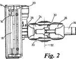
図1および図2に床用具(床掃除具)10を示すが、これは本発明による真空掃除機用の付属装置を形成している。床用具10はハウジング14から形成されたヘッド12を有するが、このハウジング14は、その下面に形成された吸引開口16を有する。回転可能なブラシバー18が、ハウジング14内で、吸引開口16の直上に支持されており、これによって、このブラシバー18で支持された剛毛すなわちビーター(beaters)は、ブラシバー18が回転するとき吸引開口16から突出し、掃除される面を掻き立てる。ブラシバー18はタービン20および駆動ベルト(図示せず)によって駆動されるが、このタービン20を通って空気が真空掃除機のモーターによって引き込まれる。ハウジング14の正確な形状、ブラシバー18の位置、そしてブラシバーを駆動するための手段は、本発明にとって重要なことではなく、ここではこれ以上説明しない。 1 and 2 show a floor utensil (floor cleaning tool) 10 which forms an attachment for a vacuum cleaner according to the present invention. The
床用具10はまたネック22を含み、このネック22は前部24および後部26を有する。前部24は、ヘッド12に対して、回動可能なカップリング28を用いて連結されているが、このカップリング28については以下で、さらに詳しく説明する。前部24は概してヘッド12から離れるように延在し、しかも前部24自体に回転可能に配設された二つの車輪30を支持している。後部26は、それを中心として車輪30が回転する軸線32と一致する軸線を中心として、前部24に対して回動可能に連結されている。後部26は、それと共に床用具が使用される真空掃除機の本体部に対して取り付けられた杖またはホースを受けるための、前部24から離れるよう突出するカラー34を有する。ホースまたは杖をカラー34上で保持するために、キャッチ36が後部26に設けられているが、もし望むのであれば、これは省略してもよい。 The
車輪30は横方向に、すなわち床用具10の通常の移動方向(図1の矢印Aによって指し示す)と直交する方向に離間している。車輪30は、それゆえ、ヘッド12の後方であってかつ回転可能なカップリング28の後方において、床用具10のネック22の両側に左右対称に存在している。各車輪30は、吸引開口16が掃除される面と平行に存在しかつ前部24が実質的に水平であるとき、車輪30が掃除される面と接触状態となるような寸法とされる。これは図3aに示すとおりである。車輪30はそれゆえ床用具10を支持し、そして床用具10が、掃除される床面を横切って移動することを可能とする。図3bに示すのは、ネック22の後部26の、軸線32を中心として前部24に対して回動する機能である。この動きは、通常使用時(この間に床用具10は床40を横切って前方に押しやられかつ後方に引き戻される)に、カラー34に取り付けられた杖(図示せず)の、床に対する傾きの変化(矢印B参照)を許容するために必要である。 The
図3aおよび図3bにはまた回動可能なカップリング28を示すが、このカップリング28によって床用具10のネック22がヘッド14に対して取り付けられている。回動可能なカップリング28は同心状に配置された二つのカラー(ヘッド12およびネック22のそれぞれに一つずつ配置されている)を具備しており、それらは互いに回動可能である。それを中心として上記カラーが回転できる軸線38は、掃除される面40に対して傾斜している(図3b参照)。軸線38が傾斜している理由について、以下で、さらに詳しく説明する。 FIGS. 3 a and 3 b also show a
図4aに示すのは、それが通常の使用状態にあるときに後方から見た床用具10である。ヘッド12は掃除される面40の上に水平状態で載っており、その結果、吸引開口16は床40と平行に存在している。カラー34が真空掃除機のホースおよび杖のアセンブリに取り付けられ、そしてモーターを作動させたとき、空気流が吸引開口16を経て床用具10内に引き込まれ、そして埃や屑が空気流と共に床用具10内に引き込まれる。同時に、空気がタービン20を経て床用具10内に引き込まれ、この結果、ブラシバー18がその軸線を中心として駆動され、そして床カバーは、そこから可能な限り多くの埃や屑が放出されるよう掻き立てられる。空気流は、床用具のネック22に沿ってホースおよび杖のアセンブリへと、そしてそこから真空掃除機の分離機構へと流動し、そこで埃や屑が分離させられると共に保持され、その一方で清浄化された空気は大気中に戻される。 Shown in FIG. 4a is the
図4aに示すポジションでは、床用具30の車輪30はいずれも床40に接している。この結果、床40との二つの接点はネック22の軸心を中心として左右対称に位置している。カラー34に対して取り付けられた杖が床40に対してなす角度の変化は、図3aおよび図3bに示すように、ネック22の後部26の回動動作によって許容される。だが、車輪30がネック22に配されているという事実は、カラー34に対して取り付けられた杖を、床用具10のステアリングを実現するために、その長手方向軸線(これは図3bに示すカラー34の長手方向軸線と一致する)を中心として捻ることができることを意味する。これは、図4bおよび図4cに示すように、床用具10のネック22を回動させることによって達成される。図4bにおいて、杖は、時計回り方向に、その軸線を中心として捻られており、この結果、ネック22は時計回り方向に軸線42を中心として同様に捻られている(矢印C参照)。これによって、左側の車輪30aが床40から離れるよう持ち上げられており、その結果、床40との唯一の接点は、ネック22の右側に位置させられた右側車輪30bの下側縁部のみとなる。(床用具10の軸心を中心とする)非対称接点を有する当該状態は、床40との接点がネック22を中心として対称に配置された図4aの状態よりも、より優れたステアリング性能をもたらす。これによって、車輪30a,30bの両方が床40と接触したままである場合よりも、極めて容易に、床用具10を右に方向転換する(旋回させる)ことが可能となる。 In the position shown in FIG. 4 a, all the
同様に、図4cは、杖が反時計回り方向に捻られ、これによってカラー34が反時計回り方向に軸線42を中心として捻られた際(矢印D参照)に、後方から見た床用具のポジションを示す。この場合、左側車輪30aは床40と接触したままであり、一方で、右側車輪30bは床から離れるよう持ち上げられている。先と同様、この接点は対称的状態から、接点がネック22の左側にのみ位置した非対称的状態へと変化する。このポジションでは、車輪30a,30bの両方が床40と接触した状態にある場合よりも、極めて容易に、床用具10を左に方向転換する(旋回させる)ことが可能となる。 Similarly, FIG. 4c shows the floor utensil viewed from the rear when the cane is twisted counterclockwise and thereby the
図4bおよび図4cには、ネック22を後部26が概して水平ポジションにある状態で示しているが、図3bに示すように、後部26が垂直線に対して傾斜した状態で、捻り動作を行えることは明白であろう。 4b and 4c show the
回転可能な上記カップリング28は、床用具10の前方移動方向(図1に矢印Aで示す)と概ね直交する平面内で、ヘッド12に対してネック22が回動することを可能とする。これは重要なことである。なぜなら、車輪30の一方が床40から離れるよう、それを持ち上げるためにネック22を回動させた場合、吸引開口16も床と平行なままであるようヘッド12が床と平行なままであることが非常に望ましいからである。吸引開口が傾くと床用具10のピックアップ性能に悪影響が及ぶが、これは、部分的には、空気がハウジングと床との間で用具内に流れ込むという理由により、そして部分的には、ブラシバーが床カバーから、その最適距離だけ離れて機能しなくなるという理由による。回動可能なカップリング28の回動機能によって、床用具10のネック22が捻られた際、吸引開口16が床40の上で水平なままでいることが可能となっている。 The
上述したように、回動可能なカップリング28は、このカップリング28のカラーが、掃除される床面40に対して傾斜させられた軸線38を中心として互いに回動することを可能にする。その理由は、杖を上記のとおり軸線42を中心として捻ったとき、軸線38の傾きによって床用具10のヘッド12が捻り動作と同じ方向に回動させられるからである。したがって、図4bに関連付けて説明したように、杖が右側に捻られ、そして左側の車輪30aが床から持ち上げられた場合、ヘッド12は右側に向って回動し、この結果、さらに容易に床用具10を障害物の周りで操作できるようになる。同様に、右側車輪30bが床から持ち上げられるよう杖を左側に捻った場合、ヘッド12は左側に向って回動し、そしてこれによって床用具10のステアリング性能がこの方向に改善される。こうした状態のもとでも、ヘッド12は床40に対して水平なままであり、この結果、吸引開口16は床と平行に存在するようになり、ピックアップ(吸い込み)性能が低下することはない。 As described above, the
上記実施形態では、床用具10のネック22の傾動は、本質的に、車輪30の一方を床から離れるよう持ち上げることを伴う。この動作を容易なものとするため、車輪30のそれぞれの周縁部の断面形状には、図4aないし図4cに示すような丸みが付けられる。これによって回動動作を行わせるのに要するトルクが最小限に抑えられる。だが、各車輪30と床との間の接点の横方向位置は、ネック22が傾くときも、ほぼ一定に保たれる。それにもかかわらず、車輪30と掃除される床40との間の接点の数は、杖の捻り動作に、したがってヘッド12に対するネック22の回動ポジションに依存する。 In the above embodiment, the tilting of the
本発明の第2実施形態を図5aないし図5cに示す。図5aないし図5cに示す床用具110と先に説明した実施形態との唯一の差異は、車輪130のサイズおよび形状である。この第2実施形態では車輪130は比較的幅広であり、しかも横方向に円弧形状となった周縁部132を有する。周縁部132は、ネック122に最も近接したポイント132aにおいて最大直径を呈し、かつそれが車輪130の側面部134と一つになるポイント132bにおいて最小直径を呈する。ポイント132aとポイント132bとの間で、上記周縁部は部分円形状の断面を有する。床用具110の残部は、上記床用具10と同一である。床用具110が図5aに示すように通常使用状態にある場合、各車輪130の周縁部132の最内部分(すなわち最大直径のポイント132a)は、掃除される面と接触状態となる。 A second embodiment of the invention is shown in FIGS. 5a to 5c. The only difference between the
カラー134に取り付けられた杖を図5bに示すように時計回り方向に捻った際、左側の車輪130aは床から離れるよう持ち上げられ、この結果、車輪130aと床との間には接点が存在しなくなる。唯一の接点は、それゆえ、右側車輪130bの周縁部132のみである。最初、捻り角が小さいとき、接点は最大直径のポイント132aに、あるいはその近傍に留まる。だが、捻り角が増大するにつれて、接点は最小直径のポイント132bの方に移動していく。これは、車輪130の幅および周縁部132の円弧形状に起因する。同様に、杖を逆方向に、すなわち反時計回りに捻った場合、接点のポジションが杖の捻り角度に依存した状態で、右側車輪130bは床から離れるよう持ち上げられ、かつ唯一の接点は床と左側車輪130aの周縁部132との間となる。杖の捻り角が増大するにつれて、床用具110の可動性(操作性)も向上する。 When the cane attached to the
本発明を上記実施形態の正確な細部に限定することを意図してはおらず、変更および改変は当業者にとって明白であろう。たとえば、床用具は、ブラシバーを駆動するよう設計されたタービンを、あるいはそれどころかブラシバーを備えている必要すらない。 It is not intended that the invention be limited to the exact details of the above embodiments, but variations and modifications will be apparent to those skilled in the art. For example, floor utensils do not need a turbine designed to drive a brush bar, or even a brush bar.
10 床用具
12 ヘッド
14 ハウジング
16 吸引開口
18 ブラシバー
20 タービン
22 ネック
24 前部
26 後部
28 カップリング
30 車輪
32 軸線
34 カラー
36 キャッチ
38 軸線
40 床
42 軸線
110 床用具
122 ネック
130 車輪
132 周縁部
134 側面部DESCRIPTION OF
Claims (7)
Translated fromJapaneseハウジングと下方に向けられた吸引開口とを具備してなるヘッドと、
前記掃除用機器のホースまたは杖に対して取り付けるべく構成されたネックと、
前記ヘッドに対する前記ネックの回動を可能とするための、前記ネックと前記ヘッドとの間の回動可能な接続部と、
掃除される面の上で付属装置を移動可能に支持するための、付属装置の前記ネックに配設された車輪機構と、を具備してなり、
前記車輪機構は前記ネックの両側に配設された一対の車輪からなり、
前記車輪の一方が、使用時に前記ネックが前記ヘッドに対して回動させられたとき、掃除される面から離間するよう持ち上がるようになっていることを特徴とする付属装置。An accessory device for a cleaning device,
A head comprising a housing and a suction opening directed downward;
A neck configured to be attached to a hose or cane of the cleaning device;
A pivotable connection between the neck and the head to allow the neck to pivot relative to the head;
A wheel mechanism disposed on the neck of the accessory device for movably supporting the accessory device on the surface to be cleaned;
The wheel mechanism comprises a pair of wheels disposed on both sides of the neck,
An attachment device wherein one of the wheels is adapted to lift away from the surface to be cleaned when the neck is rotated relative to the head in use.
Applications Claiming Priority (2)
| Application Number | Priority Date | Filing Date | Title |
|---|---|---|---|
| GB0410698AGB2413941B (en) | 2004-05-13 | 2004-05-13 | An accessory for a cleaning appliance |
| PCT/GB2005/001571WO2005110179A1 (en) | 2004-05-13 | 2005-04-22 | An accessory for a cleaning appliance |
Publications (2)
| Publication Number | Publication Date |
|---|---|
| JP2007535355A JP2007535355A (en) | 2007-12-06 |
| JP4430713B2true JP4430713B2 (en) | 2010-03-10 |
Family
ID=32526989
Family Applications (1)
| Application Number | Title | Priority Date | Filing Date |
|---|---|---|---|
| JP2007510099AExpired - LifetimeJP4430713B2 (en) | 2004-05-13 | 2005-04-22 | Accessory equipment for cleaning equipment |
Country Status (10)
| Country | Link |
|---|---|
| US (1) | US7979959B2 (en) |
| EP (1) | EP1748718B1 (en) |
| JP (1) | JP4430713B2 (en) |
| KR (1) | KR101153256B1 (en) |
| CN (1) | CN1953691B (en) |
| AU (1) | AU2005244379B2 (en) |
| CA (1) | CA2566071A1 (en) |
| GB (1) | GB2413941B (en) |
| MY (1) | MY138038A (en) |
| WO (1) | WO2005110179A1 (en) |
Families Citing this family (46)
| Publication number | Priority date | Publication date | Assignee | Title |
|---|---|---|---|---|
| CA2599303A1 (en) | 2007-08-29 | 2009-02-28 | Gbd Corp. | Surface cleaning apparatus |
| US20210401246A1 (en) | 2016-04-11 | 2021-12-30 | Omachron Intellectual Property Inc. | Surface cleaning apparatus |
| US9888817B2 (en) | 2014-12-17 | 2018-02-13 | Omachron Intellectual Property Inc. | Surface cleaning apparatus |
| US11857142B2 (en) | 2006-12-15 | 2024-01-02 | Omachron Intellectual Property Inc. | Surface cleaning apparatus having an energy storage member and a charger for an energy storage member |
| US9192269B2 (en) | 2006-12-15 | 2015-11-24 | Omachron Intellectual Property Inc. | Surface cleaning apparatus |
| US10165912B2 (en) | 2006-12-15 | 2019-01-01 | Omachron Intellectual Property Inc. | Surface cleaning apparatus |
| GB2466290B (en)* | 2008-12-19 | 2012-10-03 | Dyson Technology Ltd | Floor tool for a cleaning appliance |
| US9433332B2 (en) | 2013-02-27 | 2016-09-06 | Omachron Intellectual Property Inc. | Surface cleaning apparatus |
| US10722086B2 (en) | 2017-07-06 | 2020-07-28 | Omachron Intellectual Property Inc. | Handheld surface cleaning apparatus |
| US12156626B2 (en) | 2009-03-13 | 2024-12-03 | Omachron Intellectual Property Inc. | Surface cleaning apparatus |
| US9265395B2 (en) | 2010-03-12 | 2016-02-23 | Omachron Intellectual Property Inc. | Surface cleaning apparatus |
| CA2674758C (en)* | 2009-07-30 | 2017-02-21 | G.B.D. Corp. | Surface cleaning apparatus |
| JP6032459B2 (en)* | 2012-02-17 | 2016-11-30 | パナソニックIpマネジメント株式会社 | Vacuum cleaner suction tool and vacuum cleaner provided with the same |
| CN104797182B (en)* | 2012-12-06 | 2017-06-23 | 松下知识产权经营株式会社 | Suction member for electric vacuum cleaner and electric vacuum cleaner including the suction member for electric vacuum cleaner |
| US9320401B2 (en) | 2013-02-27 | 2016-04-26 | Omachron Intellectual Property Inc. | Surface cleaning apparatus |
| US9027198B2 (en) | 2013-02-27 | 2015-05-12 | G.B.D. Corp. | Surface cleaning apparatus |
| US9591958B2 (en) | 2013-02-27 | 2017-03-14 | Omachron Intellectual Property Inc. | Surface cleaning apparatus |
| JP2014212828A (en)* | 2013-04-23 | 2014-11-17 | パナソニック株式会社 | Suction tool of vacuum cleaner |
| US9314139B2 (en) | 2014-07-18 | 2016-04-19 | Omachron Intellectual Property Inc. | Portable surface cleaning apparatus |
| US9585530B2 (en) | 2014-07-18 | 2017-03-07 | Omachron Intellectual Property Inc. | Portable surface cleaning apparatus |
| US9420925B2 (en) | 2014-07-18 | 2016-08-23 | Omachron Intellectual Property Inc. | Portable surface cleaning apparatus |
| US9451853B2 (en) | 2014-07-18 | 2016-09-27 | Omachron Intellectual Property Inc. | Portable surface cleaning apparatus |
| US10136778B2 (en) | 2014-12-17 | 2018-11-27 | Omachron Intellectual Property Inc. | Surface cleaning apparatus |
| US10251519B2 (en) | 2014-12-17 | 2019-04-09 | Omachron Intellectual Property Inc. | Surface cleaning apparatus |
| US11950745B2 (en) | 2014-12-17 | 2024-04-09 | Omachron Intellectual Property Inc. | Surface cleaning apparatus |
| JP6899381B2 (en)* | 2016-04-18 | 2021-07-07 | シャープ株式会社 | Vacuum cleaner suction port |
| KR102504105B1 (en)* | 2016-05-12 | 2023-02-28 | 삼성전자주식회사 | Vacuum cleaner |
| CN106963289A (en)* | 2017-04-27 | 2017-07-21 | 苏州翔博清洁科技有限公司 | A kind of dust suction brush device for dust catcher |
| US11730327B2 (en) | 2020-03-18 | 2023-08-22 | Omachron Intellectual Property Inc. | Surface cleaning apparatus with removable air treatment assembly |
| US10631693B2 (en) | 2017-07-06 | 2020-04-28 | Omachron Intellectual Property Inc. | Handheld surface cleaning apparatus |
| US11666193B2 (en) | 2020-03-18 | 2023-06-06 | Omachron Intellectual Property Inc. | Surface cleaning apparatus with removable air treatment member assembly |
| US11445878B2 (en) | 2020-03-18 | 2022-09-20 | Omachron Intellectual Property Inc. | Surface cleaning apparatus with removable air treatment member assembly |
| US10750913B2 (en) | 2017-07-06 | 2020-08-25 | Omachron Intellectual Property Inc. | Handheld surface cleaning apparatus |
| US11766156B2 (en) | 2020-03-18 | 2023-09-26 | Omachron Intellectual Property Inc. | Surface cleaning apparatus with removable air treatment member assembly |
| US10842330B2 (en) | 2017-07-06 | 2020-11-24 | Omachron Intellectual Property Inc. | Handheld surface cleaning apparatus |
| US10702113B2 (en) | 2017-07-06 | 2020-07-07 | Omachron Intellectual Property Inc. | Handheld surface cleaning apparatus |
| US10506904B2 (en) | 2017-07-06 | 2019-12-17 | Omachron Intellectual Property Inc. | Handheld surface cleaning apparatus |
| US10537216B2 (en) | 2017-07-06 | 2020-01-21 | Omachron Intellectual Property Inc. | Handheld surface cleaning apparatus |
| EP3536209A1 (en) | 2018-03-05 | 2019-09-11 | Koninklijke Philips N.V. | Vacuum cleaner nozzle |
| EP3607862A1 (en)* | 2018-08-08 | 2020-02-12 | Koninklijke Philips N.V. | Vacuum cleaner nozzle |
| US11192122B2 (en) | 2018-08-13 | 2021-12-07 | Omachron Intellectual Property Inc. | Cyclonic air treatment member and surface cleaning apparatus including the same |
| US11006799B2 (en) | 2018-08-13 | 2021-05-18 | Omachron Intellectual Property Inc. | Cyclonic air treatment member and surface cleaning apparatus including the same |
| US11013384B2 (en) | 2018-08-13 | 2021-05-25 | Omachron Intellectual Property Inc. | Cyclonic air treatment member and surface cleaning apparatus including the same |
| KR102053435B1 (en) | 2019-08-12 | 2019-12-06 | 주식회사 디에스이엔티 | Printed Circuit Board Loading Device for Automatic Reversing |
| US20250213029A1 (en) | 2023-01-19 | 2025-07-03 | Sharkninja Operating Llc | Hair care appliance with powered attachment |
| US20240245190A1 (en) | 2023-01-19 | 2024-07-25 | Sharkninja Operating Llc | Identification of hair care appliance attachments |
Family Cites Families (25)
| Publication number | Priority date | Publication date | Assignee | Title |
|---|---|---|---|---|
| DE8604732U1 (en)* | 1986-02-21 | 1987-06-19 | Siemens AG, 1000 Berlin und 8000 München | Vacuum cleaner mouthpiece with a pivoting connection piece and a mouthpiece body |
| DE8809802U1 (en) | 1988-08-01 | 1989-11-30 | Siemens AG, 1000 Berlin und 8000 München | Vacuum cleaner mouthpiece |
| US5088149A (en)* | 1990-08-06 | 1992-02-18 | Tennant Company | Vacuum powered scrub head |
| DE4105012C2 (en)* | 1991-02-19 | 1994-09-29 | Fedag Romanshorn Fa | Vacuum cleaner mouthpiece |
| JPH0622885A (en)* | 1992-07-07 | 1994-02-01 | Matsushita Electric Ind Co Ltd | Vacuum cleaner |
| DE19706166C2 (en)* | 1997-02-17 | 2000-06-08 | Duepro Ag Romanshorn | Suction cleaning tool for a suction cleaning device |
| FR2773456B1 (en)* | 1998-01-14 | 2000-02-25 | Seb Sa | VACUUM CLEANER |
| US6263539B1 (en)* | 1999-12-23 | 2001-07-24 | Taf Baig | Carpet/floor cleaning wand and machine |
| DE10001467B4 (en)* | 2000-01-15 | 2004-04-08 | Düpro AG | vacuum cleaning tool |
| TR200401240T4 (en)* | 2000-01-28 | 2004-08-23 | New Ermes Europe S. P. A. | Dust and debris collection device. |
| JP2001269294A (en)* | 2000-03-23 | 2001-10-02 | Sharp Corp | Electric vacuum cleaner |
| JP3457639B2 (en)* | 2000-05-04 | 2003-10-20 | エルジー電子株式会社 | Vacuum cleaner |
| US6532622B2 (en)* | 2000-05-17 | 2003-03-18 | Daewoo Electronics Co., Ltd. | Brush head of vacuum cleaner |
| USD457696S1 (en)* | 2000-08-02 | 2002-05-21 | Düpro AG | Vacuum cleaning tool |
| DE10042671C5 (en)* | 2000-08-31 | 2010-04-15 | Düpro AG | Vacuum cleaning tool with pear-shaped turbine chamber |
| DE10042672C5 (en)* | 2000-08-31 | 2010-05-27 | Düpro AG | Vacuum cleaning tool with throughflow turbine |
| GB0023732D0 (en)* | 2000-09-28 | 2000-11-08 | Notetry Ltd | A floor tool |
| AU762499B2 (en)* | 2001-01-29 | 2003-06-26 | Lg Electronics Inc. | Extension tube in vacuum cleaner |
| US6584640B2 (en)* | 2001-03-20 | 2003-07-01 | Roger P. Vanderlinden | Large area surface cleaning tool for suctioning both dust and debris |
| GB0126494D0 (en)* | 2001-11-03 | 2002-01-02 | Dyson Ltd | A floor tool |
| JP2003153833A (en) | 2001-11-22 | 2003-05-27 | Toshiba Tec Corp | Suction port body and vacuum cleaner |
| EP1955636A3 (en)* | 2002-04-25 | 2010-04-07 | Panasonic Corporation | Vacuum-cleaner suction tool |
| GB2393383B (en)* | 2002-09-24 | 2005-12-28 | Dyson Ltd | A vacuum cleaning head |
| DE10256030A1 (en)* | 2002-11-30 | 2004-06-09 | Düpro AG | Cleaning tool with a rotating driven tool |
| US20060290000A1 (en)* | 2005-06-28 | 2006-12-28 | Wojciech Worwag | Composite metal layer formed using metal nanocrystalline particles in an electroplating bath |
- 2004
- 2004-05-13GBGB0410698Apatent/GB2413941B/ennot_activeExpired - Lifetime
- 2005
- 2005-04-22EPEP05738005.7Apatent/EP1748718B1/ennot_activeExpired - Lifetime
- 2005-04-22JPJP2007510099Apatent/JP4430713B2/ennot_activeExpired - Lifetime
- 2005-04-22USUS11/596,173patent/US7979959B2/enactiveActive
- 2005-04-22KRKR1020067026245Apatent/KR101153256B1/ennot_activeExpired - Lifetime
- 2005-04-22AUAU2005244379Apatent/AU2005244379B2/ennot_activeExpired
- 2005-04-22CNCN2005800152304Apatent/CN1953691B/ennot_activeExpired - Lifetime
- 2005-04-22CACA002566071Apatent/CA2566071A1/ennot_activeAbandoned
- 2005-04-22WOPCT/GB2005/001571patent/WO2005110179A1/enactiveApplication Filing
- 2005-05-05MYMYPI20052012Apatent/MY138038A/enunknown
Also Published As
| Publication number | Publication date |
|---|---|
| MY138038A (en) | 2009-04-30 |
| KR101153256B1 (en) | 2012-06-05 |
| EP1748718B1 (en) | 2013-09-25 |
| KR20070015961A (en) | 2007-02-06 |
| AU2005244379B2 (en) | 2008-10-30 |
| AU2005244379A1 (en) | 2005-11-24 |
| US20070226937A1 (en) | 2007-10-04 |
| GB2413941B (en) | 2007-08-15 |
| US7979959B2 (en) | 2011-07-19 |
| CN1953691A (en) | 2007-04-25 |
| EP1748718A1 (en) | 2007-02-07 |
| GB2413941A (en) | 2005-11-16 |
| CN1953691B (en) | 2010-11-10 |
| WO2005110179A1 (en) | 2005-11-24 |
| CA2566071A1 (en) | 2005-11-24 |
| JP2007535355A (en) | 2007-12-06 |
| GB0410698D0 (en) | 2004-06-16 |
Similar Documents
| Publication | Publication Date | Title |
|---|---|---|
| JP4430713B2 (en) | Accessory equipment for cleaning equipment | |
| US6374453B1 (en) | Convertible vacuum cleaner | |
| CN202288141U (en) | Floor processing device | |
| KR101148095B1 (en) | A floor tool has a surface treating appliance such as a vacuum cleaner | |
| CN100593387C (en) | vacuum cleaner | |
| JP4426151B2 (en) | Hose and straight pipe assembly | |
| US20060130268A1 (en) | Convertible vacuum cleaner | |
| CN101292849A (en) | upright vacuum cleaner | |
| JP2008526415A (en) | Surface treatment equipment | |
| JP2019532694A (en) | Cleaning head for vacuum cleaner | |
| US20180020890A1 (en) | Cleaner | |
| KR102308483B1 (en) | Cleaner head and vacuum cleaner having the same | |
| EP0136895A2 (en) | Self-cleaning joint | |
| JP2006136503A (en) | Vacuum cleaner inlet and vacuum cleaner | |
| CN102258349B (en) | Vacuum cleaner | |
| JP4726708B2 (en) | Vacuum cleaner | |
| TWI825624B (en) | Cleaner | |
| JP7400858B2 (en) | Cleaning tools, vacuum cleaners, and cordless vacuum cleaners | |
| KR101268129B1 (en) | Suction nozzle for vaccum cleaner | |
| JP6763455B2 (en) | Vacuum cleaner and vacuum cleaner | |
| JP4444075B2 (en) | Vacuum cleaner inlet and vacuum cleaner | |
| JP2000354573A (en) | Suction body for vacuum cleaner and vacuum cleaner using the same | |
| JP2005334209A (en) | Vacuum cleaner suction tool and electric vacuum cleaner using the same | |
| JPH07106191B2 (en) | Vacuum cleaner | |
| KR20030031651A (en) | Apparatus for rotating brush of vacuum cleaner |
Legal Events
| Date | Code | Title | Description |
|---|---|---|---|
| A977 | Report on retrieval | Free format text:JAPANESE INTERMEDIATE CODE: A971007 Effective date:20090129 | |
| A131 | Notification of reasons for refusal | Free format text:JAPANESE INTERMEDIATE CODE: A131 Effective date:20090203 | |
| A601 | Written request for extension of time | Free format text:JAPANESE INTERMEDIATE CODE: A601 Effective date:20090424 | |
| A602 | Written permission of extension of time | Free format text:JAPANESE INTERMEDIATE CODE: A602 Effective date:20090507 | |
| A521 | Request for written amendment filed | Free format text:JAPANESE INTERMEDIATE CODE: A523 Effective date:20090728 | |
| A131 | Notification of reasons for refusal | Free format text:JAPANESE INTERMEDIATE CODE: A131 Effective date:20090908 | |
| A521 | Request for written amendment filed | Free format text:JAPANESE INTERMEDIATE CODE: A523 Effective date:20091019 | |
| A521 | Request for written amendment filed | Free format text:JAPANESE INTERMEDIATE CODE: A523 Effective date:20091110 | |
| A521 | Request for written amendment filed | Free format text:JAPANESE INTERMEDIATE CODE: A523 Effective date:20091113 | |
| TRDD | Decision of grant or rejection written | ||
| A01 | Written decision to grant a patent or to grant a registration (utility model) | Free format text:JAPANESE INTERMEDIATE CODE: A01 Effective date:20091201 | |
| A01 | Written decision to grant a patent or to grant a registration (utility model) | Free format text:JAPANESE INTERMEDIATE CODE: A01 | |
| A61 | First payment of annual fees (during grant procedure) | Free format text:JAPANESE INTERMEDIATE CODE: A61 Effective date:20091217 | |
| FPAY | Renewal fee payment (event date is renewal date of database) | Free format text:PAYMENT UNTIL: 20121225 Year of fee payment:3 | |
| R150 | Certificate of patent or registration of utility model | Free format text:JAPANESE INTERMEDIATE CODE: R150 Ref document number:4430713 Country of ref document:JP Free format text:JAPANESE INTERMEDIATE CODE: R150 | |
| FPAY | Renewal fee payment (event date is renewal date of database) | Free format text:PAYMENT UNTIL: 20121225 Year of fee payment:3 | |
| FPAY | Renewal fee payment (event date is renewal date of database) | Free format text:PAYMENT UNTIL: 20131225 Year of fee payment:4 | |
| R250 | Receipt of annual fees | Free format text:JAPANESE INTERMEDIATE CODE: R250 | |
| R250 | Receipt of annual fees | Free format text:JAPANESE INTERMEDIATE CODE: R250 | |
| R250 | Receipt of annual fees | Free format text:JAPANESE INTERMEDIATE CODE: R250 | |
| R250 | Receipt of annual fees | Free format text:JAPANESE INTERMEDIATE CODE: R250 | |
| R250 | Receipt of annual fees | Free format text:JAPANESE INTERMEDIATE CODE: R250 | |
| R250 | Receipt of annual fees | Free format text:JAPANESE INTERMEDIATE CODE: R250 | |
| R250 | Receipt of annual fees | Free format text:JAPANESE INTERMEDIATE CODE: R250 | |
| R250 | Receipt of annual fees | Free format text:JAPANESE INTERMEDIATE CODE: R250 | |
| R250 | Receipt of annual fees | Free format text:JAPANESE INTERMEDIATE CODE: R250 | |
| R250 | Receipt of annual fees | Free format text:JAPANESE INTERMEDIATE CODE: R250 | |
| R250 | Receipt of annual fees | Free format text:JAPANESE INTERMEDIATE CODE: R250 | |
| R250 | Receipt of annual fees | Free format text:JAPANESE INTERMEDIATE CODE: R250 | |
| R250 | Receipt of annual fees | Free format text:JAPANESE INTERMEDIATE CODE: R250 | |
| EXPY | Cancellation because of completion of term |