JP4428737B2 - Red-eye detection method - Google Patents
Red-eye detection methodDownload PDFInfo
- Publication number
- JP4428737B2 JP4428737B2JP24327598AJP24327598AJP4428737B2JP 4428737 B2JP4428737 B2JP 4428737B2JP 24327598 AJP24327598 AJP 24327598AJP 24327598 AJP24327598 AJP 24327598AJP 4428737 B2JP4428737 B2JP 4428737B2
- Authority
- JP
- Japan
- Prior art keywords
- eye
- red
- image
- color
- template
- Prior art date
- Legal status (The legal status is an assumption and is not a legal conclusion. Google has not performed a legal analysis and makes no representation as to the accuracy of the status listed.)
- Expired - Lifetime
Links
Images


Classifications
- G—PHYSICS
- G06—COMPUTING OR CALCULATING; COUNTING
- G06V—IMAGE OR VIDEO RECOGNITION OR UNDERSTANDING
- G06V40/00—Recognition of biometric, human-related or animal-related patterns in image or video data
- G06V40/10—Human or animal bodies, e.g. vehicle occupants or pedestrians; Body parts, e.g. hands
- G06V40/18—Eye characteristics, e.g. of the iris
- G06V40/193—Preprocessing; Feature extraction
- G—PHYSICS
- G06—COMPUTING OR CALCULATING; COUNTING
- G06T—IMAGE DATA PROCESSING OR GENERATION, IN GENERAL
- G06T7/00—Image analysis
- G06T7/0002—Inspection of images, e.g. flaw detection
- G—PHYSICS
- G06—COMPUTING OR CALCULATING; COUNTING
- G06T—IMAGE DATA PROCESSING OR GENERATION, IN GENERAL
- G06T7/00—Image analysis
- G06T7/90—Determination of colour characteristics
- H—ELECTRICITY
- H04—ELECTRIC COMMUNICATION TECHNIQUE
- H04N—PICTORIAL COMMUNICATION, e.g. TELEVISION
- H04N1/00—Scanning, transmission or reproduction of documents or the like, e.g. facsimile transmission; Details thereof
- H04N1/46—Colour picture communication systems
- H04N1/56—Processing of colour picture signals
- H04N1/60—Colour correction or control
- H04N1/62—Retouching, i.e. modification of isolated colours only or in isolated picture areas only
- H04N1/624—Red-eye correction
- G—PHYSICS
- G06—COMPUTING OR CALCULATING; COUNTING
- G06T—IMAGE DATA PROCESSING OR GENERATION, IN GENERAL
- G06T2207/00—Indexing scheme for image analysis or image enhancement
- G06T2207/10—Image acquisition modality
- G06T2207/10024—Color image
- G—PHYSICS
- G06—COMPUTING OR CALCULATING; COUNTING
- G06T—IMAGE DATA PROCESSING OR GENERATION, IN GENERAL
- G06T2207/00—Indexing scheme for image analysis or image enhancement
- G06T2207/30—Subject of image; Context of image processing
- G06T2207/30196—Human being; Person
- G06T2207/30201—Face
- G—PHYSICS
- G06—COMPUTING OR CALCULATING; COUNTING
- G06T—IMAGE DATA PROCESSING OR GENERATION, IN GENERAL
- G06T2207/00—Indexing scheme for image analysis or image enhancement
- G06T2207/30—Subject of image; Context of image processing
- G06T2207/30216—Redeye defect
Landscapes
- Engineering & Computer Science (AREA)
- Computer Vision & Pattern Recognition (AREA)
- Physics & Mathematics (AREA)
- General Physics & Mathematics (AREA)
- Theoretical Computer Science (AREA)
- Multimedia (AREA)
- Health & Medical Sciences (AREA)
- Signal Processing (AREA)
- Quality & Reliability (AREA)
- General Health & Medical Sciences (AREA)
- Ophthalmology & Optometry (AREA)
- Human Computer Interaction (AREA)
- Image Processing (AREA)
- Stroboscope Apparatuses (AREA)
- Editing Of Facsimile Originals (AREA)
- Facsimile Image Signal Circuits (AREA)
- Image Analysis (AREA)
- Color Television Image Signal Generators (AREA)
Description
Translated fromJapanese【0001】
【発明の属する技術分野】
本発明は概してディジタル画像処理の分野に関し、更に特定的にはディジタル画像中の赤目を検出する方法に関する。
【0002】
【従来の技術】
画像の捕捉のためにフラッシュ照明が使用されるとき、画像の中の人の瞳孔は赤く見えることがある。これはフラッシュユニットからの光が瞳孔に入り、網膜上で色々な向きに反射し、最後に瞳孔を通って外に出ることによって生ずる。光は部分的に網膜の中の毛細血管によって吸収されるため、瞳孔は画像の中で赤く見える。この現象は「赤目」と称される。赤目が認められる確率はフラッシュユニットがレンズの光学軸に近いほど増加する。従って、赤目は一般的に一体型のフラッシュユニットを有する小型カメラによって捕捉された画像の中に認められる。
【0003】
共通に譲受される米国特許第5,432,863号は、赤目の色特徴を有する画像中の対象を検出するユーザ対話型の方法を記載する。この方法は形状、色彩及び明るさに基づいて候補赤目画素を自動的に検出する。
【0004】
【発明が解決しようとする課題】
現在知られている赤目を検出する方法は充分であるが、欠点が無いわけではない。米国特許第5,432,863号の方法は候補画素が顔の上に配置されている、又は人間の目の一部であるかを決定しない。
従って、上述の欠点を克服する赤目を検出する方法が必要とされる。
【0005】
【課題を解決するための手段】
本発明は上述の1つ以上の問題を克服することを目的とする。簡単に要約するに、本発明の1つの面によれば、フラッシュ照明による画像中の対称の目の色の欠陥を検出するためのコンピュータプログラム物であって、(a)ディジタル画像中の肌色領域を検出する段階と、(b)赤目欠陥の色特徴を有する画素の組に対して肌色領域をサーチする段階と、(c)上記段階(b)において見出された赤目欠陥の位置に基づいて画素の色を修正する段階とを実行するコンピュータプログラムを記憶させたコンピュータ読み取り可能な記憶媒体を含むコンピュータプログラム物が提供される。
【0006】
本発明は赤目欠陥を自動的に検出する方法を提供することを目的とする。
本発明は候補赤目欠陥が人間の顔の一部であるかどうかを決定する方法を提供することを目的とする。
本発明はまた候補赤目欠陥が人間の目の一部であるかどうかを決定する方法を提供することを目的とする。
【0007】
【発明の実施の形態】
本発明の上述及び他の面、目的、特徴及び利点は以下詳述される実施例及び添付の図面を参照して明らかとなろう。以下の説明において、ソフトウエアプログラムとしての望ましい実施例によって本発明を説明する。当業者はそのようなソフトウエアの等価物がハードウエア中に構築されうることを容易に認識するであろう。
【0008】
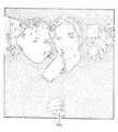
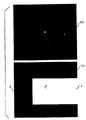
図1は2対の赤目20を示すカラー画像のグレースケール画像10を示す図である。
図2を参照するに、本発明のフローチャートの全体図が示されている。カラーディジタル画像は従来技術によって周知のコンピュータシステム上に存在するソフトウエアプログラムに入力される。ディジタル画像の符号値は元のシーンによる画像を捕捉するのに使用されるフィルムの露出の量の対数に正比例することが望ましい(S2)。プログラムは画像中の全ての別個の連続した肌色領域を同定することから開始する(S4)。
【0009】
図3を参照するに、図2のステップS4の詳細なフローチャートが示されている。まずカラー画像の赤、緑及び青の値は、R,G及びBを夫々カラー画像中の画素の赤、緑及び青の符号値とすると、以下の関係式:
【0010】
【数1】
を使用してLSTカラー空間へ変換される(S4a)。
次のステップでは3次元のヒストグラムが構築される。ヒストグラムの大きさを減少させるため、まず、L,S及びTの符号値は、夫々8.0x(3)1/2,2.0及び2.0で割り算されることによって量子化される(S4b)。これらの量子化された符号値はL’,S’及びT’と称される。L’,S’及びT’の各組み合わせはヒストグラムの「bin」と称される。ヒストグラムH(L’,S’,T’)の値は(S4c)、L’,S’及びT’の量子化された符号値を有する画像中の画素の数に等しい。換言すれば、ヒストグラムによって各binに属する画像中の画素の数が分かる。この数はbinの値と称される。
【0012】
ヒストグラムは、各binの値をそのbinの値と隣接するbinの値との加重平均によって置き換えることによって平滑化される(S4d)。次に、ヒストグラム中のピーク値が見つけられ(S4e)、ヒストグラム中の各binは最も近くに配置されるピーク値が割り当てられる(S4f)。最後に、カラー画像中の各画素はヒストグラムのbinに割り当てられており、各binはピークに割り当てられているため、ピークはカラー画像中の各画素に割り当てられる(S4g)。画素の符号値がそれが割り当てられたピークの数に等しい単一帯域画像はセグメント化された画像と称される。
【0013】
同一の符号値を有するセグメント化された画像中の連続領域はカラー画像中の対象又は対象の一部に対応しやすい。固有の番号(ラベル)はセグメント化された画像中の全てのそのような領域に割り当てられる(S4h)。番号は、最も多くの画素を有する領域に対して割り当てられる1から始まり、順次的に割り当てられる。符号値が画素の属する領域のラベルに対応する単一帯域画像はラベル付けされた画像と称される。
【0014】
プログラムは次にセグメント化された画像中のどの連続領域が人間の肌の典型的な色を有するかを決定する。各領域の平均L,S及びT符号値が計算され、これに基づいて各領域にはスコアPskinが割り当てられる(S4i)。Pskinの高い値はその領域が人間の肌の典型的な色であることを示す。或いは、低い値はその領域の色が典型的な肌の色ではないことを示す。Pskinが閾値Tskin0.10を超過する領域は肌色領域と称される(S4j)。
【0015】
カラー画像中の夫々の顔を単一の肌色領域に関連づけるために、1つの最終的な段階が必要である。上述の方法は、しばしば顔のつや、影等により顔の色が均一でないことにより、単一の顔を1つ以上の肌色領域に関連づけさせることがある。2つの肌色領域は2つの条件が満たされれば単一の肌色領域の中にマージされる(S4k)。第1の条件は、2つの領域が相互連結されることである。領域i中の画素は、領域jに属する画素が8つの最も近傍の画素のうちの1つであれば、領域jに対して連結されている。領域i及びjの画素の間の連結の数に正比例する関数Q(i,j)が計算される。関数はQ(i,j)が1.0となるよう正規化される。Q(i,j)が閾値MinMergerFraction を超過すれば、第2の条件が満たされれば、例えば閾値0.005が使用されれば、i及びjは単一の領域中にマージする。第2の条件は、
Dcolor=((Li−Lj)2+(Si−Sj)2+(Ti−Tj)2)1/2
によって与えられる領域i及びjの色の間の距離が、40.0に設定されるMaxMergeColorDistance 以下にされることである。
【0016】
肌色領域をマージする方法は、2つの条件が満たされる場合に、最小の領域をより大きな領域にマージすることから開始する。領域iがより大きな領域jにマージされる場合、次に領域jが更に大きな領域kにマージされることが起こりうる。これが起こるとき、領域i,j及びkは単一の領域にマージされる。領域i及びkは、これらの2つの領域について上述の2つの条件が満たされない場合でもマージされうることに注意すること。これらは領域jに対する相互連結によってマージされる。
【0017】
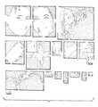
肌色検出の結果としてカラー画像中に肌色領域のマップが与えられる(S4l)。肌色でない領域はゼロの符号値が与えられる。別個の連続した肌色領域は番号1から始まって領域の大きさの降順に連続して番号が付けられる。図4は図1の肌色領域のマップを示す図である。
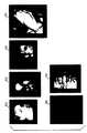
図2を参照し、また図5に図示されるように、各肌色領域のサブマップは肌マップ(図4)からその肌領域全てを含む最小の矩形セクションを切り出すことによって形成される(S6)。例えば、図5の肌領域30bは図4の肌領域30aに対応する。図5は夫々の別々の連続する肌色領域を個々のサブマップとして示す図である。サブマップの左上の隅に対応する肌マップの列及び行は夫々Colcutout及びRowcutoutと称される。サブマップでは、255の値(白)は画素が肌色が存在する位置に配置されていることを示す。ゼロの符号値(黒)は肌色がないことを示す。
【0018】
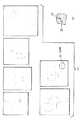
図2を参照し、図6に示されるように、次の段階において楕円形35はステップS6において見つけられた個々の肌色サブマップに当てはめられる(S8)(図5)。楕円形を2値画像に当てはめる方法は、1992年Addison-WesleyからのRobert M. Haralick 及びLinda G. Shapiroによる「Computer and Robot Vision. Volume I 」に記載されている。人間の顔はほぼ楕円形である。従って、肌色サブマップが人間の顔のものであれば、楕円は肌色マップによく当てはまり、楕円の短軸は顔の幅にほぼ等しくなるべきである。楕円形の肌色サブマップへの当てはめの尺度は、Nをマップ中の肌色画素(符号値255)の数、Noutを楕円形の外側になる肌色画素の数、Ninを楕円形の内側の肌色画素の数、またAを楕円形の中の画素の数とすると、
【0019】
【数2】
によって与えられる。Aは楕円形の面積とも称される。肌色画素の全てが楕円形の中にあり、肌色画素の数が楕円の面積と等しければ、Fitは1となり、当てはめは完全である。肌色画素が楕円の外側にある、又は楕円の面積がその中の肌色画素の数以上であるとき、Fitの値は減少される。Fitの値が0.70とされる所定の値MinEllipseFit 以下であれば、肌色領域は顔ではなく、それを更に処理しないものとする(S10)。
【0021】
肌色サブマップが顔のサブマップであるかどうかの他の印は、Dmajorを楕円形の長軸とし、Dminorを画素中の短軸とすると、
AspectRatio = Dmajor/Dminor
に与えられる楕円形のアスペクト比AspectRatio である。AspectRatio が3.0とされるMaxAspectRatio以上であれば、肌色領域は顔であるには細長すぎる画像中の対象に対応する。プログラムは肌色領域が顔ではないと決定し、これを更には処理しない(S10)。
【0022】
肌サブマップが楕円形に対する許容可能な当てはめの度合いを有し、楕円形が許容可能なアスペクト比を有する場合、マップは潜在的に顔の位置を示す。次に、75ピクセルに設定されるAimEyeDistanceを目の間の所望の距離とし、2.0に設定されるFaceWidthEyeDistanceRatio を典型的な顔に対する幅と目の間の距離との比とすると、以下の式、
Sprescale=(AimEyeDistance x FaceWidthEyeDistanceRatio)/Dminor
によって与えられるリサイズ係数Sprescaleを計算する。Sprescaleが0.10であるMinPrescale 以下であるか、又は1.50であるMaxPrescale 以上であれば、肌色領域は更には処理されない(S10)。次の段階は、カラー画像からサブマップの位置に正確に対応する副カラー画像を切り出す段階である(S12)。楕円形の短軸が顔の幅と略等しければ顔の中の目の間の距離はAimEyeDistanceに近いはずである。図7はこのようにしてリサイズされた後の副カラー画像40を示す図である。図7はグレースケールの図として示されているが、実際の画像はカラー画像であることに注意すべきである。図8はやはりリサイズされており(S14)副カラー画像の夫々に対応する楕円形50を示す図である。実際は、これらの画像が更に処理されたときに境界外の画素がアドレス指定されないよう、リサイズされた副カラー画像及びサブマップの縁に余分な行及び列を加えることが望ましい。画像の上部及び下部はパッド行によって埋められ、左側及び右側はパッド列によって埋められる。
【0023】
ここで顔の形状を有する肌色領域が同定されており、候補赤目の位置は同定される必要があり(S16)、これは図9に詳細に図示される。ここで図9を参照するに、副カラー画像40は小さな赤い特徴を同定するよう処理される。プログラムは、R,G及びBを副カラー画像の赤,緑及び青の符号値とすると、
X=R−Max(G,B)
によって与えられる画素値Xを有する新しい単一帯域画像を決めることによって開始する(S16a)。
【0024】
新しい画像の中の赤目は、高い符号値と、多分瞳孔の中のきらめき(glint )による中心の小さな低い符号値の領域とを有する小さな楕円形の面積として現れる。きらめきの影響は、例えば3x3のカーネルといったW _close x W _close のカーネルを使用することによってグレースケールの形態学的クローズ操作を実行することによって除去される(S16b)。また、3x3以外の他の大きさのカーネルも使用されうる。グレースケールの形態学的操作は1982年にAcademic Press 社から出版されたJean Serra による「Image Analysis and Mathematical Morphology Volume 1 」の第424乃至478頁を参照のこと。次に、高い符号値の小さな領域は、例えば5x5のカーネルといったW _open x W_openのカーネルを使用することによってグレースケールの形態学的オープン操作を実行することによって除去される(S16c)。また5x5以外の他の大きさのカーネルも使用されうる。残りの画像を形成するよう、オープン画像は次にクローズ画像から引き算される(S16d)。この画像はオープン画像の中にあったのものを示すが、クローズ画像の中のもの、即ち、副カラー画像中の小さな赤い特徴に対応する高い符号値の小さな領域は示さない。次に、残りの画像は以下のカーネル、即ち、
1 2 1
2 4 2
1 2 1
を有する線形フィルタを使用して平滑化される(S16e)。平滑化された残りの画像中の各画素に対して、その画素を中心として配置された7x7の窓が検査される。この画素の符号値が、5に設定された閾値Tpeakを超過し、窓の中の他の全ての画素の符号値以上であれば、その画素はピークとして分類される(S16f)。図10の(A)及び(B)は図7中の全ての副カラー画像に対するピーク37を示す図である。平滑化された残りの画像の中の全てのピークが見つけられたあと、個々のピークが検査される(S16g)。まず、画素がピークであると分類され、この画素の西、北西、北又は北東側にある隣接する画素もまたピークであると分類されたとき、ピークは除去される(S16h)。
【0025】
ピークとして分類された画素は候補赤目画素である。しかしながらピークの位置が瞳孔の中のきらめきと一致し、赤い欠陥ではないことも可能である。このため、ピークからの2に等しい距離GlintRadius より内側の画素が検査される(S16i)。候補赤目画素は以下定義される最高の色スコアPcolorを有する近傍の画素へ移動される。
【0026】
次に、候補赤目画素は類似した色の画素の連続領域を成長させるための種(seed)として使用される。領域内の画素の数がMinSize より小さいか、MaxSize より大きければ、領域は赤目欠陥の特徴である大きさではなく、候補赤目画素は除去される(S16j)。
上述の処理の結果として、各副カラー画像16kに対する候補赤目画素のマップが得られる(S16k)。図8の楕円形は、潜在的に顔であると同定された図7の対応する副カラー画像中の領域の近似したマップである。従って、図11に概説される次の段階の目の検出では、楕円の内側にある候補赤目画素のみが考慮される。
【0027】
再び図2を参照するに、目の検出の目的は候補赤目画素が実際に目の一部であるかどうかを決定することである。目の検出の手順はカラー画像の単色版を必要とする(S18)。Gを緑帯域の符号値とし、γを2.0に設定されるパラメータとすると、カラー画像の緑帯域は、緑画素符号値を以下の式、即ち、
【0028】
【数3】
を使用して変形することによってコントラストが増加された後に使用される。カラー画像の単色版はルミナンス画像と称される。
図2中の目の検出手順S20はテンプレートマッチングの方法に基づく。これは目のどの画像もテンプレートとして使用されうることに注意することによって理解が容易にされる。図12の上の画像60は左目のテンプレートを示す。下の画像70はテンプレートのゾーンへの分割を示す。ゾーン1は眉毛の領域である。ゾーン2及び3は夫々目の左側及び右側である。ゾーン4は瞳孔及び虹彩を含む。ゾーン0は使用されない。目のテンプレートは、目の間の距離が306ピクセルのTemplateEyeDistance であり、2つの目の傾斜がゼロに近い画像から得られた。上述のように、リサイズされた副カラー画像中の1対の赤目は約AimEyeDistance(75ピクセル)だけ離れているはずである。従って、テンプレートが一致するよう正しい大きさであるためには、目は以下の係数、即ち、
S0= AimEyeDistance / TemplateEyeDistance
によってリサイズされねばならない。
【0030】
実際は、楕円形の短軸からの顔の幅の推定は常に正確ではない。また、目は傾斜されうる。このため、元の左目のテンプレート及びゾーンマップから開始し、広がった範囲の大きさ及び向きの左目、右目(左目の鏡像)及びゾーンマップが形成される(S22)。元の目のテンプレート及びゾーンマップはS0x NarrowからS0x wideまでSStep の増分でリサイズされる。Narrow, Wide及びSStep の望ましい値は夫々1.5,0.50及び0.05である。各リサイズ係数に対して傾斜を適応させるために、TStep 度の増分の-MaxTilt度(時計回りの傾斜)からMaxTilt 度までの範囲の一連の傾斜されたテンプレート及びゾーンマップが生成される(S22)。MaxTilt の望ましい値は30°であり、TStep の望ましい値は2.0°である。
【0031】
図11を参照するに、図2のステップS20の詳細なフローチャートが示されている。左及び右赤目対に属すると仮定される1対の候補赤目画素を考える(S20a)。元の目のテンプレートに対する目の縮尺は、Lp(Rp)を左(右)の候補赤目画素の列であるとし、Ll(Rl)を左(右)の候補赤目画素の行であるとすると、以下の関係式、即ち、
【0032】
【数4】
によって候補赤目画素対の間の距離と関連づけられる(S20b)。(列の番号は1から開始し、左から右へ増加する。行の番号は1から開始し上から下へ増加する)。候補赤目画素の間の傾斜(S20b)は、
【0034】
【数5】
によって与えられる。
上述のように、目のテンプレート及びゾーンマップの組は、SStep の解像度のS0x NarrowからS0x wideまでのリサイズ係数の範囲及び解像度TStep で-MaxTilt度(時計回りの傾斜)からMaxTilt 度までの範囲に広がるよう形成される。候補赤目画素の対に対するSpair及びTiltの値に最もよく一致する左目テンプレート、右目テンプレート及びゾーンマップは続く相関段階で使用される。Spair及びTiltがこの範囲外であれば、この対は更なる処理をされない(S20c)。
【0036】
目のテンプレートが選択された後、次の段階では赤目画素の周囲の領域が目に一致するかどうかが決定される。これはルミナンス画像の左の候補赤目画素の周囲の領域で左目テンプレートの相関を、右の候補赤目画素の周囲の領域で右目テンプレートの相関を実行することによって行われる(S20d)。相関方法の1つの段階は、テンプレート及びルミナンス画像の画素を一致させ、それらの符号値の積を計算することである。テンプレート画像の中心は目の中心に対応する。候補赤目画素は目の中心に近いが、目の中心にある必要はないため、ここでは候補赤目画素の回りに3に等しい距離LookAroundに亘って広がる方形の中の全ての画素に一致されるテンプレートの中心に対して数回相関を行う。相関はテンプレートのゾーン1からゾーン4に対して別々に行われる(図12参照)。これらの相関はCz1,Cz2,Cz3及びCz4と称される。更に、ゾーン1からゾーン4までの合計からなる領域に対して全体の相関が計算される。全体の相関Cの最も高い値を有する候補赤目画素の周囲の方形の中の画素は、候補赤目画素を含む目の中心の最もよい推測である。この画素は目の中心の画素と称される。左及び右の候補赤目画素は共に関連する目の中心の画素を有する。
【0037】
ここで相関処理を詳述する。pを列の番号とし、lを行の番号とすると、テンプレート画像は関数Φ(p,l)によって示される。テンプレートの中の列及び行の番号は夫々w及びhである。目のテンプレートの中心は略目の中心の位置である。テンプレートのゾーンは、p∈Zが列pがゾーンZにあることを意味し、l∈Zが行lがゾーンZにあることを意味し、NZはゾーンの中の画素の数であるときに、
【0038】
【数6】
によって与えられる積Πによって、列p0及び行l0においてΓ(p,l)によって示されるルミナンス画像と相関される。また、
【0040】
【数7】
によって与えられるゾーンZの中のテンプレートの平均符号値が計算される。更に、ゾーンZの中のテンプレートの標準偏差は、以下の式、
【0042】
【数8】
によって計算される。同様に、ゾーンZの中のルミナンス画像の平均符号値は以下の式、
【0044】
【数9】
によって計算され、標準偏差は以下の式、
【0046】
【数10】
によって計算される。
上述によって定義された量を使用して、ルミナンス画像のゾーンZの中のテンプレートとの相関は、以下の関係式、
【0048】
【数11】
によって与えられる。画像及びテンプレートの符号値がゾーン1の中で全く同じであれば、CZは1.0となる。画像及びテンプレートが完全に相関されていなければCZはゼロとなる。
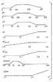
目の中心の画素に対するC,CZ1,CZ2,CZ3及びCZ4の値は、候補赤目画素の対が副カラー画像中の赤目欠陥の一部である可能性の尺度であるスコアの計算に使用される(S20e)。相関は夫々0.0乃至1.0の範囲の関連するスコアリング関数の中の変数として使用される。例えば、目の中心の画素に対するCの値が画素が実際に目の中心に配置されている可能性が非常に低いことを示す場合、pC(C)と称される全体の相関Cに関連するスコアリング関数は0.0となる。一方、Cの値が目のテンプレートの相関の典型的な範囲である場合、pC(C)は1.0となる。そうでなければ、pC(C)は中間値を取る。スコアリング関数pC(C)及び後述される他のスコアリング関数は図13に示される。
【0050】
後に候補赤目対に対する全体のスコアと組み合わせられるスコアはこれらのスコアリング関数に基づいて定義される。以下の式は全体の相関Cに関するスコアPcorrを、
Pcorr=pC(C)
として簡単に定義する。ゾーン相関に関連するスコアPzoneはゾーン相関スコアリング関数の加重平均である。ゾーン4(瞳孔)の中の相関は目の存在に関して他のゾーンよりもはるかに信頼できる指標であることが分かっている。このためゾーン4の相関は他のゾーンよりも多くの重みをあたえられている。典型的には、重みWを6.0とする。Pzoneは、
【0051】
【数12】
によって与えられる。
全体の相関Cの計算過程において計算された
【0053】
【外1】
は、目の中心の画素に中心を合わせられたルミナンス画像の中の特徴が実際に目であればよい指標であることが分かっている。例えば、
【0055】
【外2】
が非常に低ければ、特徴が目であるには低すぎるコントラストを有する。これを考慮したうえで、
【0057】
【外3】
に関連するスコアを、
【0059】
【数13】
によって定義する。
最後に、候補赤目画素の色は実際の赤目欠陥を示すものでなくてはならない。この計算のために、候補赤目画素の赤、緑及び青の符号値はルミナンス(Lum )、色調(Hue )及び飽和(Sat )の値に変換される。ルミナンスは、
【0061】
【数14】
によって計算される。画素の対するLum の値はゼロから可能な限り高い符号値までの範囲を取る。飽和は以下の式、
【0063】
【数15】
によって与えられ、0から100までの値の範囲を取る。色調は、赤色は120度の色調角へ変位される以外は、Addison-Wesley Publishing Company 出版の「Computer Graphics Principles and Practice 2nd ed. 」の第592頁と同様に定義される。Hue の値は0乃至360度の範囲を取りうる。候補赤目画素の色に関連するスコアは、
Pcolor=pL(Lum)pH(Hue)pS(Sat)
によって定義される。
【0065】
結果は、候補赤目画素が実際に画像中の赤目欠陥の一部である可能性を示すスコアPeyeである。このスコアは、
Peye=PcorrPzonePsigmaPcolor
によって定義され、その値は0.0から1.0までの範囲を取る。対の中の左び右の候補赤目画素の両方に対して良さの尺度Peyeが計算される。これらの2つの値の平均は、
【0066】
【数16】
によって与えられる。Ppairが最大となる候補赤目画素の対は候補赤目画素の最善の対と称される(S20f)。Ppairが0.05である閾値MinEyeScore を超過すれば、プログラムは更なる処理を行う。そうでなければ、プログラムは副カラー画像の中に1対の赤目がないと決定する(S20g)。
カラー画像中の赤目欠陥を有する対の一部でない候補赤目画素の最善の対が誤って分類される確率を最小化させることが重要である。赤目の対が実際に配置されていることを確かめる1つの方法は、人間の顔が顔を二分する線に対して略対称であることを使用することである(図2のS24)。これを行うため、副カラー画像は候補赤目画素の最善の対を連結する線の傾斜が略ゼロであるよう回転される。次に、副カラー画像から目の間の中点を中心とされた画像が切り出される。この画像は候補赤目画素の間の距離の1.5倍の幅と、その幅の4分の1の高さを有する。この画像は次に半分に切断される。ここで添え字xはカラー画像の帯域を示すとすると、左半分の画像は、Exleft(p,l) と称され、右半分の画像は、Exright(p,l) と称される。例えば、Erleft p,l)は画像の赤の帯域を示す。右半分の画像の中の列はそれ自体の構造となるよう反転される(最初の列が最後の列になる等)。Exleft(p,l) とExright(p,l) との相関はまず、p 及びl に亘る総和は夫々半分の画像の列及び行の全てに対するものであり、Nは半分の画像の中の画素数であるとして、積の和、即ち、
【0068】
【数17】
を計算することによって実行される。相関は、Mxleft及びMxrightを半分の画像の帯域xの平均符号値とし、σxleft及びσxrightを標準偏差とすると、
【0070】
【数18】
によって与えられる。スコアPsymは対称スコアリング関数pSym(Cxsym )に基づいて、
Psym=pSym(Crsym )pSym(Cgsym )pSym(Cbsym )
によって定義される。
最終的なスコアPは端にPsym及びPpairの積、即ち、
P=PsymPpair
である。この0.0から1.0までの範囲を取りうるスコアが0.05に設定されている閾値MinScoreを超える場合(S26)、候補赤目対はリサイズされた副カラー画像の中の赤目欠陥の対の位置をマークすると考えられる。
【0072】
最後に、原カラー画像の中の左及び右の赤目欠陥の位置は、p 及びl をリサイズされた副カラー画像中の左の候補赤目画素の列及び行とし、p'及びl'を原カラー画像中の対応する位置とすると、以下の関係式、
【0073】
【数19】
を使用してリサイズされた副カラー画像の左及び右の候補赤目画素に基づいて計算される(S28)。
時々、楕円形に当てはめられた後の2つの異なる肌領域が重なり合う、又は互いに非常に近接することがある。これによって、同じ赤目対が2回見つけられる、又は互いに近すぎる2つの赤目対の検出が真に赤目対であるとされうる。このため、カラー画像中の全ての赤目対が配置された後、いずれかの2つの対が20ピクセルのMinInterpairEyeDistance よりも小さい赤目位置を有するかどうかが決定される。この場合、より低いスコアを有する対は除去される(S30)。
【図面の簡単な説明】
【図1】赤目を示す図である。
【図2】本発明のソフトウエアプログラムのフローチャートを示す全体図である。
【図3】図2の連続する肌色領域を決定する部分の詳細なフローチャートを示す図である。
【図4】肌色領域を示す図1の2値表現である。
【図5】図4の個々の連続する色領域の詳細図を示す図である。
【図6】図5のに当てはめられる楕円形を示す図である。
【図7】リサイズされた候補顔領域を示す図である。
【図8】図7に当てはめられた候補顔領域に対応するリサイズされた楕円形を示す図である。
【図9】図2の候補赤目決定部分の詳細なフローチャートである。
【図10】図7の候補赤目欠陥を示す図である。
【図11】図2の目の検出の部分の詳細なフローチャートである。
【図12】目のテンプレート及びゾーンマップを示す図である。
【図13】本発明のスコアリング関数を示す図である。
【符号の説明】
10 グレースケール画像
20 赤目
30a,30b 肌領域
35 楕円形
37 ピーク
40 副カラー画像
50 楕円形
60 上の画像
70 下の画像[0001]
BACKGROUND OF THE INVENTION
The present invention relates generally to the field of digital image processing, and more particularly to a method for detecting red eyes in a digital image.
[0002]
[Prior art]
When flash illumination is used for image capture, the human pupil in the image may appear red. This is caused by light from the flash unit entering the pupil, reflecting in various directions on the retina, and finally exiting through the pupil. The pupil appears red in the image because the light is partially absorbed by the capillaries in the retina. This phenomenon is called “red eye”. The probability that red eyes will be recognized increases as the flash unit is closer to the optical axis of the lens. Thus, red eyes are generally observed in images captured by a small camera having an integral flash unit.
[0003]
Commonly assigned US Pat. No. 5,432,863 describes a user interactive method of detecting objects in an image having red-eye color features. This method automatically detects candidate red-eye pixels based on shape, color and brightness.
[0004]
[Problems to be solved by the invention]
Although currently known methods for detecting red eyes are sufficient, they are not without drawbacks. The method of US Pat. No. 5,432,863 does not determine whether the candidate pixel is located on the face or is part of the human eye.
Therefore, there is a need for a method for detecting red eyes that overcomes the above-mentioned drawbacks.
[0005]
[Means for Solving the Problems]
The present invention is directed to overcoming one or more of the problems as set forth above. Briefly summarized, according to one aspect of the present invention, there is provided a computer program product for detecting symmetric eye color defects in an image caused by flash illumination, comprising: (a) a skin color region in a digital image; (B) based on the position of the red eye defect found in step (b) above, (b) searching for a skin color region for a set of pixels having color characteristics of a red eye defect A computer program product is provided that includes a computer readable storage medium having stored thereon a computer program for performing the step of correcting the color of a pixel.
[0006]
It is an object of the present invention to provide a method for automatically detecting red eye defects.
The present invention seeks to provide a method for determining whether a candidate red-eye defect is part of a human face.
The present invention also aims to provide a method for determining whether a candidate red-eye defect is part of a human eye.
[0007]
DETAILED DESCRIPTION OF THE INVENTION
The above and other aspects, objects, features and advantages of the present invention will become apparent with reference to the following detailed description and accompanying drawings. In the following description, the present invention will be described by way of a preferred embodiment as a software program. Those skilled in the art will readily recognize that equivalents of such software can be built into the hardware.
[0008]
FIG. 1 is a diagram showing a
Referring to FIG. 2, an overall flow chart of the present invention is shown. The color digital image is input into a software program that resides on a computer system known from the prior art. The sign value of the digital image is preferably directly proportional to the logarithm of the amount of film exposure used to capture the image from the original scene (S2). The program starts by identifying all the distinct continuous skin color regions in the image (S4).
[0009]
Referring to FIG. 3, a detailed flowchart of step S4 of FIG. 2 is shown. First, the red, green, and blue values of the color image are represented by the following relational expressions where R, G, and B are the red, green, and blue code values of the pixels in the color image, respectively:
[0010]
[Expression 1]
Is converted into the LST color space (S4a).
In the next step, a three-dimensional histogram is constructed. In order to reduce the size of the histogram, first, the sign values of L, S and T are 8.0x (3) respectively.1/2, 2.0 and 2.0 are divided to be quantized (S4b). These quantized code values are referred to as L ', S' and T '. Each combination of L ′, S ′, and T ′ is referred to as a “bin” in the histogram. The value of the histogram H (L ', S', T ') is (S4c), equal to the number of pixels in the image having the quantized code values of L', S 'and T'. In other words, the number of pixels in the image belonging to each bin can be known from the histogram. This number is called the value of bin.
[0012]
The histogram is smoothed by replacing each bin value with a weighted average of the bin value and the adjacent bin value (S4d). Next, a peak value in the histogram is found (S4e), and each bin in the histogram is assigned a peak value located closest to it (S4f). Finally, since each pixel in the color image is assigned to a bin of the histogram, and each bin is assigned to a peak, the peak is assigned to each pixel in the color image (S4g). A single band image in which the sign value of a pixel is equal to the number of peaks to which it is assigned is referred to as a segmented image.
[0013]
A continuous region in a segmented image having the same code value tends to correspond to an object or part of an object in a color image. A unique number (label) is assigned to all such regions in the segmented image (S4h). Numbers are assigned sequentially starting with 1 assigned to the region with the most pixels. A single-band image whose code value corresponds to the label of the area to which the pixel belongs is called a labeled image.
[0014]
The program then determines which continuous regions in the segmented image have the typical color of human skin. The average L, S and T code values for each region are calculated, and based on this, each region has a score PskinIs assigned (S4i). PskinA high value of indicates that the region is a typical color of human skin. Alternatively, a low value indicates that the color of the area is not a typical skin color. PskinIs the threshold TskinA region exceeding 0.10 is referred to as a skin color region (S4j).
[0015]
One final step is required to associate each face in the color image with a single skin color region. The methods described above often associate a single face with one or more skin color regions due to non-uniform face color due to face shine, shadows, and the like. Two skin color regions are merged into a single skin color region if two conditions are satisfied (S4k). The first condition is that the two regions are interconnected. A pixel in region i is connected to region j if the pixel belonging to region j is one of the eight nearest pixels. A function Q (i, j) that is directly proportional to the number of connections between the pixels in regions i and j is calculated. The function is normalized so that Q (i, j) is 1.0. If Q (i, j) exceeds the threshold MinMergerFraction, i and j merge into a single region if the second condition is met, eg if threshold 0.005 is used. The second condition is
Dcolor= ((Li-Lj)2+ (Si-Sj)2+ (Ti-Tj)2)1/2
The distance between the colors of the regions i and j given by is below the MaxMergeColorDistance set to 40.0.
[0016]
The method of merging skin color regions starts with merging the smallest region into a larger region when two conditions are met. If region i is merged into a larger region j, then region j may be merged into a larger region k. When this happens, regions i, j and k are merged into a single region. Note that regions i and k can be merged even if the above two conditions are not met for these two regions. These are merged by interconnection for region j.
[0017]
As a result of the skin color detection, a map of the skin color area is given in the color image (S4l). A non-skin color area is given a code value of zero. Separate consecutive skin color regions are numbered sequentially starting with number 1 and in descending order of region size. FIG. 4 is a diagram showing a map of the skin color area of FIG.
Referring to FIG. 2 and as shown in FIG. 5, the submap of each skin color region is formed by cutting out the smallest rectangular section including all the skin regions from the skin map (FIG. 4) (S6). . For example, the skin region 30b in FIG. 5 corresponds to the skin region 30a in FIG. FIG. 5 is a diagram showing each separate continuous skin color region as an individual submap. The skin map columns and rows corresponding to the upper left corner of the submap are Col respectively.cutoutAnd RowcutoutIt is called. In the submap, a value of 255 (white) indicates that the pixel is arranged at a position where the skin color exists. A code value of zero (black) indicates no skin color.
[0018]
Referring to FIG. 2, as shown in FIG. 6, in the next stage the
[0019]
[Expression 2]
Given by. A is also referred to as an oval area. If all the skin color pixels are in an ellipse and the number of skin color pixels is equal to the area of the ellipse, Fit is 1, and the fit is complete. When the skin color pixels are outside the ellipse, or the area of the ellipse is equal to or greater than the number of skin color pixels in the ellipse, the value of Fit is decreased. If the Fit value is less than or equal to the predetermined value MinEllipseFit that is 0.70, the skin color area is not a face and is not further processed (S10).
[0021]
Another indication of whether the skin color submap is a face submap is DmajorIs the major axis of the ellipse, and DminorIs the short axis in the pixel,
AspectRatio = Dmajor/ Dminor
Is the aspect ratio of the ellipse given by. If the AspectRatio is equal to or greater than MaxAspectRatio of 3.0, the skin color area corresponds to a target in an image that is too long to be a face. The program determines that the skin color area is not a face, and does not process this further (S10).
[0022]
If the skin submap has an acceptable degree of fit to the ellipse and the ellipse has an acceptable aspect ratio, the map potentially indicates the position of the face. Next, let AimEyeDistance set to 75 pixels be the desired distance between the eyes, and FaceWidthEyeDistanceRatio set to 2.0 be the ratio of the width for a typical face to the distance between the eyes: ,
Sprescale= (AimEyeDistance x FaceWidthEyeDistanceRatio) / Dminor
Resizing factor S given byprescaleCalculate SprescaleIs less than MinPrescale which is 0.10 or more than MaxPrescale which is 1.50, the skin color region is not further processed (S10). The next step is a step of cutting out a sub color image corresponding to the position of the sub map accurately from the color image (S12). If the ellipse minor axis is approximately equal to the face width, the distance between the eyes in the face should be close to AimEyeDistance. FIG. 7 is a diagram showing the
[0023]
Here, a skin color region having a face shape has been identified, and the position of the candidate red eye needs to be identified (S16), which is illustrated in detail in FIG. Referring now to FIG. 9, the
X = R-Max (G, B)
Start by determining a new single-band image having a pixel value X given by (S16a).
[0024]
The red eye in the new image appears as a small elliptical area with a high code value and possibly a small low code value region centered by glint in the pupil. The effect of glitter is removed by performing a grayscale morphological close operation by using a W_close x W_close kernel, eg, a 3x3 kernel (S16b). Also, kernels of other sizes than 3x3 can be used. See pages 424-478 of "Image Analysis and Mathematical Morphology Volume 1" by Jean Serra, published by Academic Press in 1982 for grayscale morphological manipulation. Next, small regions of high code values are removed by performing a grayscale morphological open operation by using a W_open x W_open kernel, eg, a 5x5 kernel (S16c). Other sizes of kernels other than 5x5 can also be used. The open image is then subtracted from the closed image to form the remaining image (S16d). This image shows what was in the open image, but not in the closed image, i.e., the small region of high code value corresponding to the small red feature in the secondary color image. Next, the remaining images are the following kernels:
1 2 1
2 4 2
1 2 1
Is smoothed using a linear filter having (S16e). For each pixel in the remaining smoothed image, a 7x7 window centered on that pixel is examined. The threshold value T set to 5 for the sign value of this pixelpeakIf it exceeds the sign value of all other pixels in the window, the pixel is classified as a peak (S16f). 10A and 10B are
[0025]
Pixels classified as peaks are candidate red-eye pixels. However, it is possible that the peak position coincides with the glitter in the pupil and is not a red defect. For this reason, pixels inside a distance GlintRadius equal to 2 from the peak are inspected (S16i). The candidate red-eye pixel has the highest color score P defined belowcolorIs moved to a neighboring pixel having.
[0026]
The candidate red eye pixel is then used as a seed for growing a continuous region of similarly colored pixels. If the number of pixels in the region is smaller than MinSize or larger than MaxSize, the region is not the size characteristic of the red-eye defect, and the candidate red-eye pixel is removed (S16j).
As a result of the above processing, a candidate red-eye pixel map for each sub-color image 16k is obtained (S16k). The ellipse in FIG. 8 is an approximate map of the region in the corresponding sub-color image of FIG. 7 that has been identified as potentially a face. Therefore, in the next stage of eye detection outlined in FIG. 11, only candidate red-eye pixels inside the ellipse are considered.
[0027]
Referring again to FIG. 2, the purpose of eye detection is to determine whether the candidate red-eye pixel is actually part of the eye. The eye detection procedure requires a single color version of the color image (S18). When G is a code value of the green band and γ is a parameter set to 2.0, the green band of the color image has a green pixel code value represented by the following equation:
[0028]
[Equation 3]
Used after the contrast is increased by deforming using. A monochromatic version of a color image is called a luminance image.
The eye detection procedure S20 in FIG. 2 is based on a template matching method. This is facilitated by noting that any image of the eye can be used as a template. The
S0= AimEyeDistance / TemplateEyeDistance
Must be resized by.
[0030]
In practice, the estimation of the face width from the elliptical minor axis is not always accurate. The eyes can also be tilted. Therefore, starting from the original left eye template and zone map, the left eye, right eye (mirror image of the left eye), and zone map of the size and direction of the expanded range are formed (S22). The original eye template and zone map is S0x Narrow to S0Resized in increments of SStep to x wide. Desirable values of Narrow, Wide and SStep are 1.5, 0.50 and 0.05, respectively. In order to adapt the slope for each resizing factor, a series of sloped templates and zone maps ranging from -MaxTilt degrees (clockwise slope) in increments of TStep degrees to MaxTilt degrees are generated (S22). . A desirable value for MaxTilt is 30 ° and a desirable value for TStep is 2.0 °.
[0031]
Referring to FIG. 11, a detailed flowchart of step S20 of FIG. 2 is shown. Consider a pair of candidate red-eye pixels assumed to belong to the left and right red-eye pairs (S20a). The eye scale relative to the original eye template is Lp(Rp) Is a column of left (right) candidate red-eye pixels, and Ll(Rl) Is the row of left (right) candidate red-eye pixels,
[0032]
[Expression 4]
Is associated with the distance between the candidate red-eye pixel pair (S20b). (Column numbers start at 1 and increase from left to right. Row numbers start at 1 and increase from top to bottom). The slope (S20b) between candidate red-eye pixels is
[0034]
[Equation 5]
Given by.
As described above, the eye template and zone map pair is SStep resolution S.0x Narrow to S0The resizing factor ranges up to x wide and the resolution TStep is formed so as to extend from -MaxTilt degree (clockwise tilt) to MaxTilt degree. S for candidate red-eye pixel pairspairAnd the left eye template, right eye template and zone map that best match the values of Tilt and Tilt are used in subsequent correlation steps. SpairIf Tilt is outside this range, the pair is not further processed (S20c).
[0036]
After the eye template is selected, the next step is to determine if the area around the red eye pixel matches the eye. This is performed by executing the correlation of the left eye template in the area around the left candidate red-eye pixel of the luminance image and the correlation of the right eye template in the area around the right candidate red-eye pixel (S20d). One stage of the correlation method is to match the pixels of the template and luminance image and calculate the product of their code values. The center of the template image corresponds to the center of the eye. The candidate red-eye pixel is close to the center of the eye, but need not be in the center of the eye, so here a template that matches all pixels in a square that extends around the distance LookAround equal to 3 around the candidate red-eye pixel Correlate several times to the center of Correlation is performed separately for zones 1 to 4 of the template (see FIG. 12). These correlations are referred to as Cz1, Cz2, Cz3 and Cz4. Furthermore, the overall correlation is calculated for the region consisting of the sum of zone 1 to
[0037]
Here, the correlation processing will be described in detail. The template image is represented by the function Φ (p, l), where p is the column number and l is the row number. The column and row numbers in the template are w and h, respectively. The center of the eye template is approximately the center position of the eye. The zone of the template means that pεZ means column p is in zone Z, lεZ means row l is in zone Z, NZIs the number of pixels in the zone,
[0038]
[Formula 6]
The column p by the product given by0And row l0Is correlated with the luminance image denoted by Γ (p, l). Also,
[0040]
[Expression 7]
The average sign value of the template in zone Z given by is calculated. Further, the standard deviation of the template in zone Z is given by the following equation:
[0042]
[Equation 8]
Is calculated by Similarly, the average sign value of the luminance image in zone Z is given by
[0044]
[Equation 9]
The standard deviation is calculated by the following formula:
[0046]
[Expression 10]
Is calculated by
Using the quantities defined above, the correlation of the luminance image with the template in zone Z is given by the following relation:
[0048]
## EQU11 ##
Given by. If the sign values of the image and template are exactly the same in zone 1, CZBecomes 1.0. C if image and template are not fully correlatedZBecomes zero.
C, C for the center pixel of the eyeZ1, CZ2, CZ3And CZ4Is used to calculate a score that is a measure of the likelihood that a pair of candidate red-eye pixels is part of a red-eye defect in the secondary color image (S20e). The correlation is used as a variable in the associated scoring function ranging from 0.0 to 1.0 respectively. For example, if the value of C for the center pixel of the eye indicates that it is very unlikely that the pixel is actually located in the center of the eye, it is related to the overall correlation C called pC (C) The scoring function is 0.0. On the other hand, when the value of C is within a typical range of eye template correlation, pC (C) is 1.0. Otherwise, pC (C) takes an intermediate value. The scoring function pC (C) and other scoring functions described below are shown in FIG.
[0050]
A score that is later combined with the overall score for the candidate red-eye pair is defined based on these scoring functions. The following equation gives the score P for the overall correlation CcorrThe
Pcorr= PC (C)
As a simple definition. Score P related to zone correlationzoneIs the weighted average of the zone correlation scoring function. It has been found that the correlation in zone 4 (pupil) is a much more reliable indicator of eye presence than other zones. For this reason, the correlation of
[0051]
[Expression 12]
Given by.
Calculated in the process of calculating the overall correlation C
[0053]
[Outside 1]
Has been found to be a good indicator if the feature in the luminance image centered on the center pixel of the eye is actually the eye. For example,
[0055]
[Outside 2]
Is very low, the feature has a contrast that is too low to be eye. With this in mind,
[0057]
[Outside 3]
Scores related to
[0059]
[Formula 13]
Defined by.
Finally, the color of the candidate red eye pixel must indicate the actual red eye defect. For this calculation, the red, green and blue sign values of the candidate red-eye pixel are converted to luminance (Lum), hue (Hue) and saturation (Sat) values. The luminance is
[0061]
[Expression 14]
Is calculated by The Lum value for a pixel ranges from zero to the highest possible sign value. Saturation is:
[0063]
[Expression 15]
And takes a range of values from 0 to 100. The tone is defined in the same way as page 592 of “Computer Graphics Principles and Practice 2nd ed.” Published by Addison-Wesley Publishing Company, except that red is displaced to a tone angle of 120 degrees. The Hue value can range from 0 to 360 degrees. The score associated with the color of the candidate red-eye pixel is
Pcolor= PL (Lum) pH (Hue) pS (Sat)
Defined by
[0065]
The result is a score P indicating that the candidate red-eye pixel may actually be part of a red-eye defect in the image.eyeIt is. This score is
Peye= PcorrPzonePsigmaPcolor
And its value ranges from 0.0 to 1.0. Goodness measure P for both left and right candidate red-eye pixels in the paireyeIs calculated. The average of these two values is
[0066]
[Expression 16]
Given by. PpairThe pair of candidate red-eye pixels that maximizes is referred to as the best candidate red-eye pixel pair (S20f). PpairIf the threshold MinEyeScore, which is 0.05, is exceeded, the program performs further processing. Otherwise, the program determines that there is no pair of red eyes in the secondary color image (S20g).
It is important to minimize the probability that the best pair of candidate red-eye pixels that are not part of a pair with red-eye defects in the color image will be misclassified. One way to verify that the pair of red eyes is actually placed is to use that the human face is approximately symmetrical with respect to the line that bisects the face (S24 in FIG. 2). To do this, the secondary color image is rotated so that the slope of the line connecting the best pair of candidate red-eye pixels is approximately zero. Next, an image centered at the midpoint between the eyes is cut out from the sub-color image. This image has a width that is 1.5 times the distance between candidate red-eye pixels and a height that is a quarter of that width. This image is then cut in half. Here, if the subscript x indicates the band of the color image, the left half image is Exleft(p, l) and the right half of the image is Exrightcalled (p, l). For example, Erleft p, l) indicates the red band of the image. The columns in the right half of the image are inverted to have their own structure (eg the first column becomes the last column). Exleft(p, l) and ExrightThe correlation with (p, l) is first the sum of products, assuming that the sum over p and l is for all columns and rows of the half image, respectively, and N is the number of pixels in the half image. That is,
[0068]
[Expression 17]
It is executed by calculating The correlation is MxleftAnd MxrightIs the average code value of the band x of the half image, and σxleftAnd σxrightIs the standard deviation.
[0070]
[Expression 18]
Given by. Score PsymIs the symmetric scoring function pSym (Cxsym)
Psym= PSym (Crsym) pSym (Cgsym) pSym (Cbsym)
Defined by
The final score P is P at the endsymAnd PpairProduct, i.e.
P = PsymPpair
It is. When the score that can take the range from 0.0 to 1.0 exceeds the threshold MinScore set to 0.05 (S26), the candidate red-eye pair is a pair of red-eye defects in the resized sub-color image. It is thought to mark the position of.
[0072]
Finally, the positions of the left and right red-eye defects in the original color image are p and l as the columns and rows of left candidate red-eye pixels in the resized sub-color image, and p 'and l' are the original color. Assuming the corresponding position in the image,
[0073]
[Equation 19]
Is calculated based on the left and right candidate red-eye pixels of the sub-color image resized using (S28).
Sometimes two different skin areas after being fitted to an ellipse may overlap or be very close to each other. This allows the same red eye pair to be found twice, or the detection of two red eye pairs that are too close to each other to be truly red eye pairs. Thus, after all the red-eye pairs in the color image have been placed, it is determined whether any two pairs have a red-eye position smaller than the 20 pixel MinInterpairEyeDistance. In this case, pairs with lower scores are removed (S30).
[Brief description of the drawings]
FIG. 1 is a diagram showing red eyes.
FIG. 2 is an overall view showing a flowchart of a software program of the present invention.
FIG. 3 is a diagram showing a detailed flowchart of a portion for determining continuous skin color regions in FIG. 2;
4 is a binary representation of FIG. 1 showing a skin color region.
5 shows a detailed view of each successive color region of FIG. 4;
6 is a diagram showing an ellipse applied to FIG. 5. FIG.
FIG. 7 is a diagram showing a resized candidate face area;
8 shows a resized ellipse corresponding to the candidate face region fitted in FIG.
FIG. 9 is a detailed flowchart of a candidate red-eye determination part in FIG. 2;
FIG. 10 is a diagram showing the candidate red-eye defect of FIG.
FIG. 11 is a detailed flowchart of the eye detection portion of FIG. 2;
FIG. 12 is a diagram showing an eye template and a zone map.
FIG. 13 is a diagram showing a scoring function of the present invention.
[Explanation of symbols]
10 Grayscale image
20 red eyes
30a, 30b Skin area
35 oval
37 peak
40 secondary color image
50 oval
60 Images on
70 Lower image
Claims (4)
Translated fromJapaneseディジタル画像の全体を、顔の特徴を有する1つ又は複数の肌色領域を前記ディジタル画像において検出するためにサーチする段階と、
通常の顔の目の間の所定の距離に基づいて肌色領域それぞれをリサイズする段階と、
候補赤目欠陥を形成するために、赤目欠陥の色特徴を有する画素群を求めて、前記リサイズされた肌色領域をサーチする段階と、
目のテンプレート、及び前記目のテンプレートの個々のゾーンを含むゾーン・マップを選択する段階であって、前記選択する段階は、特定の範囲の大きさ及び傾きの向きにわたる左目のテンプレート、右目のテンプレート、及びゾ―ン・マップから行われ、前記選択する段階は、候補赤目欠陥の対について、前記候補赤目欠陥の対の傾斜、及び前記候補赤目欠陥の対間の距離に基づいて行われる段階と、
前記候補赤目欠陥の対のうちの候補赤目欠陥それぞれの周囲の領域を、前記選択された目のテンプレートと相関させる段階であって、前記相関させる段階が、前記個々のゾーン毎に別個に行われる段階と、
前記候補赤目欠陥の対の色を修正する段階と
を含む方法。A method for detecting a color defect in an eye of an object in an image by flash illumination,
Searching the entire digital image to detect one or more skin color regions having facial features in the digital image;
Resizing each skin color region based on a predetermined distance between the eyes of a normal face;
Searching for the resized skin color region for a pixel group having a red eye defect color feature to form a candidate red eye defect;
Selecting a zone map that includes an eye template and individual zones of the eye template, the selecting step comprising: left eye template, right eye template over a specific range of magnitudes and tilt directions , and zone - performed from down map, said step of selecting is for a pair of candidate redeye defects,the inclination of said pair of candidate redeye defects, and the stepsto be performed basedon the distance between said pair of candidate redeye defects,
Correlating a region aroundeach candidate red- eye defect inthe candidate red-eye defectpair with theselected eye template, wherein the correlating is performed separately for each individual zone. Stages,
Correcting thecandidate red-eye defectpair color; and
Including methods.
前記左目のテンプレート、前記右目のテンプレート、及び前記ゾーン・マップの前記大きさの特定の範囲が、狭い大きさから広い大きさまでの増分の大きさにわたる方法。The method of claim 1, comprising:
The eye template, the right template, and how a particular range of the size of the zone map,over the size of the increments to large size from a narrow size.
負の最大傾斜角度(時計回りの傾斜)から正の最大傾斜角度までの範囲にわたる方法。4. The method of claim 3, wherein the specific range of tilt orientations of the left eye template, the right eye template, and the zone map is a negative maximum tilt angle (clock) in a predetermined angle increment. methodranging from around the tilt) to a positive maximum inclination angle.
Applications Claiming Priority (2)
| Application Number | Priority Date | Filing Date | Title |
|---|---|---|---|
| US08/919,560US6292574B1 (en) | 1997-08-29 | 1997-08-29 | Computer program product for redeye detection |
| US919560 | 1997-08-29 |
Publications (2)
| Publication Number | Publication Date |
|---|---|
| JPH11136498A JPH11136498A (en) | 1999-05-21 |
| JP4428737B2true JP4428737B2 (en) | 2010-03-10 |
Family
ID=25442312
Family Applications (1)
| Application Number | Title | Priority Date | Filing Date |
|---|---|---|---|
| JP24327598AExpired - LifetimeJP4428737B2 (en) | 1997-08-29 | 1998-08-28 | Red-eye detection method |
Country Status (3)
| Country | Link |
|---|---|
| US (1) | US6292574B1 (en) |
| EP (1) | EP0899686A3 (en) |
| JP (1) | JP4428737B2 (en) |
Families Citing this family (124)
| Publication number | Priority date | Publication date | Assignee | Title |
|---|---|---|---|---|
| US6786420B1 (en) | 1997-07-15 | 2004-09-07 | Silverbrook Research Pty. Ltd. | Data distribution mechanism in the form of ink dots on cards |
| US6618117B2 (en) | 1997-07-12 | 2003-09-09 | Silverbrook Research Pty Ltd | Image sensing apparatus including a microcontroller |
| US6985207B2 (en) | 1997-07-15 | 2006-01-10 | Silverbrook Research Pty Ltd | Photographic prints having magnetically recordable media |
| US20040160524A1 (en)* | 1997-07-15 | 2004-08-19 | Kia Silverbrook | Utilising exposure information for image processing in a digital image camera |
| US7110024B1 (en) | 1997-07-15 | 2006-09-19 | Silverbrook Research Pty Ltd | Digital camera system having motion deblurring means |
| US7246897B2 (en)* | 1997-07-15 | 2007-07-24 | Silverbrook Research Pty Ltd | Media cartridge for inkjet printhead |
| US7551201B2 (en) | 1997-07-15 | 2009-06-23 | Silverbrook Research Pty Ltd | Image capture and processing device for a print on demand digital camera system |
| US7077515B2 (en) | 1997-07-15 | 2006-07-18 | Silverbrook Research Pty Ltd | Media cartridge for inkjet printhead |
| US7593058B2 (en)* | 1997-07-15 | 2009-09-22 | Silverbrook Research Pty Ltd | Digital camera with integrated inkjet printer having removable cartridge containing ink and media substrate |
| US6690419B1 (en) | 1997-07-15 | 2004-02-10 | Silverbrook Research Pty Ltd | Utilising eye detection methods for image processing in a digital image camera |
| US6879341B1 (en) | 1997-07-15 | 2005-04-12 | Silverbrook Research Pty Ltd | Digital camera system containing a VLIW vector processor |
| AUPO799997A0 (en) | 1997-07-15 | 1997-08-07 | Silverbrook Research Pty Ltd | Image processing method and apparatus (ART10) |
| AUPO802797A0 (en) | 1997-07-15 | 1997-08-07 | Silverbrook Research Pty Ltd | Image processing method and apparatus (ART54) |
| US7705891B2 (en)* | 1997-07-15 | 2010-04-27 | Silverbrook Research Pty Ltd | Correction of distortions in digital images |
| US7714889B2 (en)* | 1997-07-15 | 2010-05-11 | Silverbrook Research Pty Ltd | Digital camera using exposure information for image processing |
| US7551202B2 (en)* | 1997-07-15 | 2009-06-23 | Silverbrook Research Pty Ltd | Digital camera with integrated inkjet printer |
| US6624848B1 (en) | 1997-07-15 | 2003-09-23 | Silverbrook Research Pty Ltd | Cascading image modification using multiple digital cameras incorporating image processing |
| AUPO850597A0 (en)* | 1997-08-11 | 1997-09-04 | Silverbrook Research Pty Ltd | Image processing method and apparatus (art01a) |
| US7738015B2 (en) | 1997-10-09 | 2010-06-15 | Fotonation Vision Limited | Red-eye filter method and apparatus |
| US7042505B1 (en) | 1997-10-09 | 2006-05-09 | Fotonation Ireland Ltd. | Red-eye filter method and apparatus |
| US7352394B1 (en) | 1997-10-09 | 2008-04-01 | Fotonation Vision Limited | Image modification based on red-eye filter analysis |
| US7630006B2 (en) | 1997-10-09 | 2009-12-08 | Fotonation Ireland Limited | Detecting red eye filter and apparatus using meta-data |
| JPH11175699A (en)* | 1997-12-12 | 1999-07-02 | Fuji Photo Film Co Ltd | Picture processor |
| US6631208B1 (en)* | 1998-05-29 | 2003-10-07 | Fuji Photo Film Co., Ltd. | Image processing method |
| JP2000048184A (en)* | 1998-05-29 | 2000-02-18 | Canon Inc | Image processing method and face region extraction method and apparatus |
| AUPP400998A0 (en) | 1998-06-10 | 1998-07-02 | Canon Kabushiki Kaisha | Face detection in digital images |
| AUPP702098A0 (en) | 1998-11-09 | 1998-12-03 | Silverbrook Research Pty Ltd | Image creation method and apparatus (ART73) |
| AU4691400A (en)* | 1999-05-03 | 2000-11-17 | Pictuality, Inc. | Image analysis process |
| AUPQ056099A0 (en) | 1999-05-25 | 1999-06-17 | Silverbrook Research Pty Ltd | A method and apparatus (pprint01) |
| AU769886B2 (en)* | 2000-03-01 | 2004-02-05 | Canon Kabushiki Kaisha | Segmenting an image |
| US7092122B2 (en)* | 2000-07-18 | 2006-08-15 | Fuji Photo Film Co., Ltd. | Image processing device and method |
| JP2002043200A (en)* | 2000-07-24 | 2002-02-08 | Mitsubishi Electric Corp | Error cause detection device and error cause detection method |
| US6728401B1 (en)* | 2000-08-17 | 2004-04-27 | Viewahead Technology | Red-eye removal using color image processing |
| US6711286B1 (en)* | 2000-10-20 | 2004-03-23 | Eastman Kodak Company | Method for blond-hair-pixel removal in image skin-color detection |
| US6792134B2 (en) | 2000-12-19 | 2004-09-14 | Eastman Kodak Company | Multi-mode digital image processing method for detecting eyes |
| US6920237B2 (en)* | 2000-12-19 | 2005-07-19 | Eastman Kodak Company | Digital image processing method and computer program product for detecting human irises in an image |
| US20020081003A1 (en)* | 2000-12-27 | 2002-06-27 | Sobol Robert E. | System and method for automatically enhancing graphical images |
| US6895112B2 (en)* | 2001-02-13 | 2005-05-17 | Microsoft Corporation | Red-eye detection based on red region detection with eye confirmation |
| JP4190739B2 (en)* | 2001-02-19 | 2008-12-03 | 日本電気株式会社 | Image feature value generating apparatus and method, and storage medium storing image feature value generating program |
| US7092554B2 (en)* | 2001-05-01 | 2006-08-15 | Eastman Kodak Company | Method for detecting eye and mouth positions in a digital image |
| US20020172419A1 (en)* | 2001-05-15 | 2002-11-21 | Qian Lin | Image enhancement using face detection |
| JP4778158B2 (en)* | 2001-05-31 | 2011-09-21 | オリンパス株式会社 | Image selection support device |
| US6895103B2 (en)* | 2001-06-19 | 2005-05-17 | Eastman Kodak Company | Method for automatically locating eyes in an image |
| US6980691B2 (en) | 2001-07-05 | 2005-12-27 | Corel Corporation | Correction of “red-eye” effects in images |
| EP1293933A1 (en)* | 2001-09-03 | 2003-03-19 | Agfa-Gevaert AG | Method for automatically detecting red-eye defects in photographic image data |
| US7133070B2 (en)* | 2001-09-20 | 2006-11-07 | Eastman Kodak Company | System and method for deciding when to correct image-specific defects based on camera, scene, display and demographic data |
| US7058209B2 (en)* | 2001-09-20 | 2006-06-06 | Eastman Kodak Company | Method and computer program product for locating facial features |
| US7155058B2 (en)* | 2002-04-24 | 2006-12-26 | Hewlett-Packard Development Company, L.P. | System and method for automatically detecting and correcting red eye |
| JP2004053324A (en)* | 2002-07-17 | 2004-02-19 | Denso Corp | Collision safety controller for automobile |
| US7035461B2 (en)* | 2002-08-22 | 2006-04-25 | Eastman Kodak Company | Method for detecting objects in digital images |
| US7035462B2 (en)* | 2002-08-29 | 2006-04-25 | Eastman Kodak Company | Apparatus and method for processing digital images having eye color defects |
| US7397969B2 (en)* | 2002-08-30 | 2008-07-08 | Fujifilm Corporation | Red eye compensation method, image processing apparatus and method for implementing the red eye compensation method, as well as printing method and printer |
| US20040093432A1 (en)* | 2002-11-07 | 2004-05-13 | Eastman Kodak Company | Method and system for conducting image processing from a mobile client device |
| US7116820B2 (en)* | 2003-04-28 | 2006-10-03 | Hewlett-Packard Development Company, Lp. | Detecting and correcting red-eye in a digital image |
| US7224850B2 (en)* | 2003-05-13 | 2007-05-29 | Microsoft Corporation | Modification of red-eye-effect in digital image |
| DE60314851D1 (en)* | 2003-05-19 | 2007-08-23 | St Microelectronics Sa | Image processing method for numerical images with exposure correction by detection of skin areas of the object |
| US20040239968A1 (en)* | 2003-06-02 | 2004-12-02 | Gondek Jay S. | Color correction in images |
| US8170294B2 (en) | 2006-11-10 | 2012-05-01 | DigitalOptics Corporation Europe Limited | Method of detecting redeye in a digital image |
| US7574016B2 (en) | 2003-06-26 | 2009-08-11 | Fotonation Vision Limited | Digital image processing using face detection information |
| US7920723B2 (en) | 2005-11-18 | 2011-04-05 | Tessera Technologies Ireland Limited | Two stage detection for photographic eye artifacts |
| US7689009B2 (en) | 2005-11-18 | 2010-03-30 | Fotonation Vision Ltd. | Two stage detection for photographic eye artifacts |
| US7536036B2 (en) | 2004-10-28 | 2009-05-19 | Fotonation Vision Limited | Method and apparatus for red-eye detection in an acquired digital image |
| US8254674B2 (en) | 2004-10-28 | 2012-08-28 | DigitalOptics Corporation Europe Limited | Analyzing partial face regions for red-eye detection in acquired digital images |
| US8036458B2 (en) | 2007-11-08 | 2011-10-11 | DigitalOptics Corporation Europe Limited | Detecting redeye defects in digital images |
| US7587085B2 (en) | 2004-10-28 | 2009-09-08 | Fotonation Vision Limited | Method and apparatus for red-eye detection in an acquired digital image |
| US7792970B2 (en) | 2005-06-17 | 2010-09-07 | Fotonation Vision Limited | Method for establishing a paired connection between media devices |
| US7970182B2 (en) | 2005-11-18 | 2011-06-28 | Tessera Technologies Ireland Limited | Two stage detection for photographic eye artifacts |
| US8520093B2 (en) | 2003-08-05 | 2013-08-27 | DigitalOptics Corporation Europe Limited | Face tracker and partial face tracker for red-eye filter method and apparatus |
| US9412007B2 (en) | 2003-08-05 | 2016-08-09 | Fotonation Limited | Partial face detector red-eye filter method and apparatus |
| US20050031224A1 (en)* | 2003-08-05 | 2005-02-10 | Yury Prilutsky | Detecting red eye filter and apparatus using meta-data |
| US7454040B2 (en)* | 2003-08-29 | 2008-11-18 | Hewlett-Packard Development Company, L.P. | Systems and methods of detecting and correcting redeye in an image suitable for embedded applications |
| US7333653B2 (en)* | 2003-08-29 | 2008-02-19 | Hewlett-Packard Development Company, L.P. | Detecting and correcting redeye in an image |
| US7835572B2 (en)* | 2003-09-30 | 2010-11-16 | Sharp Laboratories Of America, Inc. | Red eye reduction technique |
| JP4345622B2 (en)* | 2003-11-05 | 2009-10-14 | オムロン株式会社 | Eye color estimation device |
| US7684642B2 (en)* | 2004-03-03 | 2010-03-23 | Eastman Kodak Company | Correction of redeye defects in images of humans |
| JP2005316958A (en)* | 2004-03-30 | 2005-11-10 | Fuji Photo Film Co Ltd | Red eye detection device, method, and program |
| JP4505362B2 (en)* | 2004-03-30 | 2010-07-21 | 富士フイルム株式会社 | Red-eye detection apparatus and method, and program |
| US7852377B2 (en)* | 2004-04-16 | 2010-12-14 | Arcsoft, Inc. | Automatic red eye removal |
| JP4496465B2 (en)* | 2004-04-23 | 2010-07-07 | ノーリツ鋼機株式会社 | Red-eye correction method, program, and apparatus for implementing the method |
| US20050248664A1 (en)* | 2004-05-07 | 2005-11-10 | Eastman Kodak Company | Identifying red eye in digital camera images |
| JP4574249B2 (en)* | 2004-06-29 | 2010-11-04 | キヤノン株式会社 | Image processing apparatus and method, program, and imaging apparatus |
| JP4599110B2 (en)* | 2004-07-30 | 2010-12-15 | キヤノン株式会社 | Image processing apparatus and method, imaging apparatus, and program |
| WO2006011635A1 (en)* | 2004-07-30 | 2006-02-02 | Canon Kabushiki Kaisha | Image processing method and apparatus, image sensing apparatus, and program |
| US8000505B2 (en)* | 2004-09-01 | 2011-08-16 | Eastman Kodak Company | Determining the age of a human subject in a digital image |
| US7623707B2 (en)* | 2004-09-15 | 2009-11-24 | Adobe Systems Incorporated | Hierarchically locating a feature in a digital image |
| US8081818B2 (en)* | 2004-09-15 | 2011-12-20 | Adobe Systems Incorporated | Locating a feature in a digital image |
| US7444017B2 (en)* | 2004-11-10 | 2008-10-28 | Eastman Kodak Company | Detecting irises and pupils in images of humans |
| JP4405942B2 (en) | 2005-06-14 | 2010-01-27 | キヤノン株式会社 | Image processing apparatus and method |
| JP4420459B2 (en)* | 2005-06-14 | 2010-02-24 | キヤノン株式会社 | Image processing apparatus and method |
| JP4498224B2 (en)* | 2005-06-14 | 2010-07-07 | キヤノン株式会社 | Image processing apparatus and method |
| US20070036438A1 (en)* | 2005-08-15 | 2007-02-15 | Lexmark International, Inc. | Methods and systems for identifying red eye pairs |
| US7747071B2 (en)* | 2005-10-27 | 2010-06-29 | Hewlett-Packard Development Company, L.P. | Detecting and correcting peteye |
| US7599577B2 (en) | 2005-11-18 | 2009-10-06 | Fotonation Vision Limited | Method and apparatus of correcting hybrid flash artifacts in digital images |
| GB2432659A (en)* | 2005-11-28 | 2007-05-30 | Pixology Software Ltd | Face detection in digital images |
| JP4712563B2 (en)* | 2006-01-16 | 2011-06-29 | 富士フイルム株式会社 | Face detection method, apparatus and program |
| EP1987475A4 (en) | 2006-02-14 | 2009-04-22 | Fotonation Vision Ltd | Automatic detection and correction of non-red eye flash defects |
| EP2033142B1 (en) | 2006-06-12 | 2011-01-26 | Tessera Technologies Ireland Limited | Advances in extending the aam techniques from grayscale to color images |
| US8064694B2 (en)* | 2006-06-21 | 2011-11-22 | Hewlett-Packard Development Company, L.P. | Nonhuman animal integument pixel classification |
| US20080170778A1 (en)* | 2007-01-15 | 2008-07-17 | Huitao Luo | Method and system for detection and removal of redeyes |
| US8055067B2 (en) | 2007-01-18 | 2011-11-08 | DigitalOptics Corporation Europe Limited | Color segmentation |
| JP2010520567A (en) | 2007-03-05 | 2010-06-10 | フォトネーション ビジョン リミテッド | Red-eye false detection filtering using face position and orientation |
| US20090024687A1 (en)* | 2007-07-20 | 2009-01-22 | Thomas Quigley | Method and system for formatting returned result from remote processing resource in wireless system |
| US7755802B2 (en)* | 2007-08-24 | 2010-07-13 | Eastman Kodak Company | Toner-based noise reduction in electrostatography |
| US8031970B2 (en)* | 2007-08-27 | 2011-10-04 | Arcsoft, Inc. | Method of restoring closed-eye portrait photo |
| JP2009080522A (en)* | 2007-09-25 | 2009-04-16 | Mitsubishi Electric Corp | Object image recognition device |
| US8503818B2 (en) | 2007-09-25 | 2013-08-06 | DigitalOptics Corporation Europe Limited | Eye defect detection in international standards organization images |
| US8391596B2 (en)* | 2007-10-17 | 2013-03-05 | Qualcomm Incorporated | Effective red eye removal in digital images without face detection |
| US8212864B2 (en) | 2008-01-30 | 2012-07-03 | DigitalOptics Corporation Europe Limited | Methods and apparatuses for using image acquisition data to detect and correct image defects |
| CN101983507A (en)* | 2008-02-01 | 2011-03-02 | 惠普开发有限公司 | Automatic redeye detection |
| US8331666B2 (en)* | 2008-03-03 | 2012-12-11 | Csr Technology Inc. | Automatic red eye artifact reduction for images |
| US8081254B2 (en) | 2008-08-14 | 2011-12-20 | DigitalOptics Corporation Europe Limited | In-camera based method of detecting defect eye with high accuracy |
| JP4912374B2 (en)* | 2008-09-10 | 2012-04-11 | 富士フイルム株式会社 | Face illustration drawing generation method and face illustration drawing generation apparatus |
| JP4640490B2 (en)* | 2008-10-24 | 2011-03-02 | コニカミノルタビジネステクノロジーズ株式会社 | Program for correcting red eye in image, recording medium, and red eye correction method |
| US8818091B2 (en) | 2011-03-21 | 2014-08-26 | Apple Inc. | Red-eye removal using multiple recognition channels |
| US8837785B2 (en)* | 2011-03-21 | 2014-09-16 | Apple Inc. | Red-eye removal using multiple recognition channels |
| US8786735B2 (en)* | 2011-03-21 | 2014-07-22 | Apple Inc. | Red-eye removal using multiple recognition channels |
| US8837822B2 (en) | 2011-03-21 | 2014-09-16 | Apple Inc. | Red-eye removal using multiple recognition channels |
| US8837827B2 (en) | 2011-03-21 | 2014-09-16 | Apple Inc. | Red-eye removal using multiple recognition channels |
| US8571271B2 (en) | 2011-05-26 | 2013-10-29 | Microsoft Corporation | Dual-phase red eye correction |
| US8811683B2 (en) | 2011-06-02 | 2014-08-19 | Apple Inc. | Automatic red-eye repair using multiple recognition channels |
| US9041954B2 (en) | 2011-06-07 | 2015-05-26 | Hewlett-Packard Development Company, L.P. | Implementing consistent behavior across different resolutions of images |
| US8970902B2 (en) | 2011-09-19 | 2015-03-03 | Hewlett-Packard Development Company, L.P. | Red-eye removal systems and method for variable data printing (VDP) workflows |
| US9378564B2 (en)* | 2013-03-01 | 2016-06-28 | Colormodules Inc. | Methods for color correcting digital images and devices thereof |
| JP6188453B2 (en) | 2013-06-28 | 2017-08-30 | キヤノン株式会社 | Image processing apparatus, image processing method, and program |
Family Cites Families (26)
| Publication number | Priority date | Publication date | Assignee | Title |
|---|---|---|---|---|
| JPS60217353A (en)* | 1984-04-13 | 1985-10-30 | Fuji Photo Film Co Ltd | Detection for flesh color |
| US5130935A (en)* | 1986-03-31 | 1992-07-14 | Canon Kabushiki Kaisha | Color image processing apparatus for extracting image data having predetermined color information from among inputted image data and for correcting inputted image data in response to the extracted image data |
| US5128711A (en)* | 1989-04-28 | 1992-07-07 | Fuji Photo Film Co., Ltd. | Apparatus for recording position information of principal image and method of detecting principal image |
| US5150433A (en)* | 1989-12-01 | 1992-09-22 | Eastman Kodak Company | Histogram/variance mechanism for detecting presence of an edge within block of image data |
| US5130789A (en)* | 1989-12-13 | 1992-07-14 | Eastman Kodak Company | Localized image recoloring using ellipsoid boundary function |
| US5089976A (en)* | 1990-07-18 | 1992-02-18 | Friends Of The Ucsd Library, Inc. | Color normalization process |
| JP2522859B2 (en)* | 1990-12-14 | 1996-08-07 | 日産自動車株式会社 | Eye position detection device |
| JP3030126B2 (en)* | 1991-07-15 | 2000-04-10 | 三洋電機株式会社 | Image processing method |
| JP3346799B2 (en)* | 1992-08-24 | 2002-11-18 | 株式会社日立製作所 | Sign language interpreter |
| US5680481A (en)* | 1992-05-26 | 1997-10-21 | Ricoh Corporation | Facial feature extraction method and apparatus for a neural network acoustic and visual speech recognition system |
| JP3036285B2 (en)* | 1993-03-05 | 2000-04-24 | ミノルタ株式会社 | Red eye position detector |
| JP3387071B2 (en)* | 1993-04-20 | 2003-03-17 | ソニー株式会社 | Image identification apparatus and method |
| JP3358033B2 (en)* | 1993-06-25 | 2002-12-16 | オリンパス光学工業株式会社 | Image correction device and image correction method |
| US5432863A (en)* | 1993-07-19 | 1995-07-11 | Eastman Kodak Company | Automated detection and correction of eye color defects due to flash illumination |
| JP2757756B2 (en)* | 1993-12-24 | 1998-05-25 | 日本電気株式会社 | Eye corner detection device |
| JP3395344B2 (en)* | 1994-04-20 | 2003-04-14 | 日産自動車株式会社 | Image processing device and doze alarm device using the same |
| JPH08138024A (en)* | 1994-11-04 | 1996-05-31 | Konica Corp | Picture direction discriminating method |
| JPH08149480A (en)* | 1994-11-25 | 1996-06-07 | Matsushita Electric Ind Co Ltd | Image coding device |
| US5724456A (en)* | 1995-03-31 | 1998-03-03 | Polaroid Corporation | Brightness adjustment of images using digital scene analysis |
| EP0735509B1 (en)* | 1995-03-31 | 1999-01-27 | Hitachi Europe Limited | Image processing for facial feature extraction |
| JP3355068B2 (en)* | 1995-07-14 | 2002-12-09 | 三菱電機株式会社 | Face image processing device |
| JPH0950528A (en)* | 1995-08-09 | 1997-02-18 | Nippon Telegr & Teleph Corp <Ntt> | Person detection device |
| JP3510040B2 (en) | 1996-03-26 | 2004-03-22 | コニカミノルタホールディングス株式会社 | Image processing method |
| JP2907120B2 (en)* | 1996-05-29 | 1999-06-21 | 日本電気株式会社 | Red-eye detection correction device |
| US6009209A (en) | 1997-06-27 | 1999-12-28 | Microsoft Corporation | Automated removal of red eye effect from a digital image |
| US6016354A (en) | 1997-10-23 | 2000-01-18 | Hewlett-Packard Company | Apparatus and a method for reducing red-eye in a digital image |
- 1997
- 1997-08-29USUS08/919,560patent/US6292574B1/ennot_activeExpired - Lifetime
- 1998
- 1998-08-17EPEP98202756Apatent/EP0899686A3/ennot_activeWithdrawn
- 1998-08-28JPJP24327598Apatent/JP4428737B2/ennot_activeExpired - Lifetime
Also Published As
| Publication number | Publication date |
|---|---|
| US6292574B1 (en) | 2001-09-18 |
| EP0899686A3 (en) | 2000-06-14 |
| EP0899686A2 (en) | 1999-03-03 |
| JPH11136498A (en) | 1999-05-21 |
Similar Documents
| Publication | Publication Date | Title |
|---|---|---|
| JP4428737B2 (en) | Red-eye detection method | |
| US6252976B1 (en) | Computer program product for redeye detection | |
| US7035461B2 (en) | Method for detecting objects in digital images | |
| JP3810776B2 (en) | A method for detecting and correcting red eyes in digital images. | |
| JP4861806B2 (en) | Red-eye detection and correction | |
| US7444017B2 (en) | Detecting irises and pupils in images of humans | |
| US7403654B2 (en) | Enhanced automatic red eye removal | |
| US7852377B2 (en) | Automatic red eye removal | |
| KR0158038B1 (en) | Apparatus for identifying person | |
| JP4153108B2 (en) | Image processing method, image processing apparatus, and recording medium | |
| US20080170778A1 (en) | Method and system for detection and removal of redeyes | |
| JP3506958B2 (en) | Image processing method, image processing apparatus, and recording medium | |
| JP4868530B2 (en) | Image recognition device | |
| EP1970859B1 (en) | Detecting method and detecting system for positions of face parts | |
| JPH0863597A (en) | Face extracting method | |
| CN107220624A (en) | A kind of method for detecting human face based on Adaboost algorithm | |
| CN104917935B (en) | Image processing apparatus and image processing method | |
| KR20040088518A (en) | Detection and correction of red-eye features in digital images | |
| JP2008146650A (en) | Adapted red eye compensation | |
| US20110164825A1 (en) | Dot templates for object detection in images | |
| CN113506275B (en) | A method of image processing based on panoramic city | |
| US20070036438A1 (en) | Methods and systems for identifying red eye pairs | |
| JP2008004123A (en) | Apparatus and method for extracting specific shape area, apparatus and method for extracting specific area, copying condition determining apparatus and method | |
| CN109872337A (en) | A method for optic disc segmentation of fundus images based on fast mean shift | |
| EP1779320A1 (en) | Image processing apparatus and method, image sensig apparatus, and program |
Legal Events
| Date | Code | Title | Description |
|---|---|---|---|
| A621 | Written request for application examination | Free format text:JAPANESE INTERMEDIATE CODE: A621 Effective date:20050819 | |
| A131 | Notification of reasons for refusal | Free format text:JAPANESE INTERMEDIATE CODE: A131 Effective date:20070424 | |
| A521 | Request for written amendment filed | Free format text:JAPANESE INTERMEDIATE CODE: A523 Effective date:20070723 | |
| A02 | Decision of refusal | Free format text:JAPANESE INTERMEDIATE CODE: A02 Effective date:20070821 | |
| A521 | Request for written amendment filed | Free format text:JAPANESE INTERMEDIATE CODE: A523 Effective date:20071119 | |
| A911 | Transfer to examiner for re-examination before appeal (zenchi) | Free format text:JAPANESE INTERMEDIATE CODE: A911 Effective date:20080104 | |
| A912 | Re-examination (zenchi) completed and case transferred to appeal board | Free format text:JAPANESE INTERMEDIATE CODE: A912 Effective date:20080222 | |
| A601 | Written request for extension of time | Free format text:JAPANESE INTERMEDIATE CODE: A601 Effective date:20090218 | |
| A601 | Written request for extension of time | Free format text:JAPANESE INTERMEDIATE CODE: A601 Effective date:20090219 | |
| A602 | Written permission of extension of time | Free format text:JAPANESE INTERMEDIATE CODE: A602 Effective date:20090224 | |
| A521 | Request for written amendment filed | Free format text:JAPANESE INTERMEDIATE CODE: A523 Effective date:20091109 | |
| A01 | Written decision to grant a patent or to grant a registration (utility model) | Free format text:JAPANESE INTERMEDIATE CODE: A01 | |
| A61 | First payment of annual fees (during grant procedure) | Free format text:JAPANESE INTERMEDIATE CODE: A61 Effective date:20091215 | |
| FPAY | Renewal fee payment (event date is renewal date of database) | Free format text:PAYMENT UNTIL: 20121225 Year of fee payment:3 | |
| R150 | Certificate of patent or registration of utility model | Free format text:JAPANESE INTERMEDIATE CODE: R150 | |
| FPAY | Renewal fee payment (event date is renewal date of database) | Free format text:PAYMENT UNTIL: 20121225 Year of fee payment:3 | |
| FPAY | Renewal fee payment (event date is renewal date of database) | Free format text:PAYMENT UNTIL: 20131225 Year of fee payment:4 | |
| S111 | Request for change of ownership or part of ownership | Free format text:JAPANESE INTERMEDIATE CODE: R313113 | |
| R350 | Written notification of registration of transfer | Free format text:JAPANESE INTERMEDIATE CODE: R350 | |
| R250 | Receipt of annual fees | Free format text:JAPANESE INTERMEDIATE CODE: R250 | |
| R250 | Receipt of annual fees | Free format text:JAPANESE INTERMEDIATE CODE: R250 | |
| R250 | Receipt of annual fees | Free format text:JAPANESE INTERMEDIATE CODE: R250 | |
| R250 | Receipt of annual fees | Free format text:JAPANESE INTERMEDIATE CODE: R250 | |
| R250 | Receipt of annual fees | Free format text:JAPANESE INTERMEDIATE CODE: R250 | |
| EXPY | Cancellation because of completion of term |