JP4426854B2 - Electronic endoscope device - Google Patents
Electronic endoscope deviceDownload PDFInfo
- Publication number
- JP4426854B2 JP4426854B2JP2004018898AJP2004018898AJP4426854B2JP 4426854 B2JP4426854 B2JP 4426854B2JP 2004018898 AJP2004018898 AJP 2004018898AJP 2004018898 AJP2004018898 AJP 2004018898AJP 4426854 B2JP4426854 B2JP 4426854B2
- Authority
- JP
- Japan
- Prior art keywords
- electronic endoscope
- signal
- processor device
- line
- adapter unit
- Prior art date
- Legal status (The legal status is an assumption and is not a legal conclusion. Google has not performed a legal analysis and makes no representation as to the accuracy of the status listed.)
- Expired - Fee Related
Links
Images


Classifications
- G—PHYSICS
- G09—EDUCATION; CRYPTOGRAPHY; DISPLAY; ADVERTISING; SEALS
- G09G—ARRANGEMENTS OR CIRCUITS FOR CONTROL OF INDICATING DEVICES USING STATIC MEANS TO PRESENT VARIABLE INFORMATION
- G09G5/00—Control arrangements or circuits for visual indicators common to cathode-ray tube indicators and other visual indicators
- G09G5/003—Details of a display terminal, the details relating to the control arrangement of the display terminal and to the interfaces thereto
- G09G5/006—Details of the interface to the display terminal
- A—HUMAN NECESSITIES
- A61—MEDICAL OR VETERINARY SCIENCE; HYGIENE
- A61B—DIAGNOSIS; SURGERY; IDENTIFICATION
- A61B1/00—Instruments for performing medical examinations of the interior of cavities or tubes of the body by visual or photographical inspection, e.g. endoscopes; Illuminating arrangements therefor
- A61B1/00112—Connection or coupling means
- A61B1/00114—Electrical cables in or with an endoscope
- A—HUMAN NECESSITIES
- A61—MEDICAL OR VETERINARY SCIENCE; HYGIENE
- A61B—DIAGNOSIS; SURGERY; IDENTIFICATION
- A61B1/00—Instruments for performing medical examinations of the interior of cavities or tubes of the body by visual or photographical inspection, e.g. endoscopes; Illuminating arrangements therefor
- A61B1/04—Instruments for performing medical examinations of the interior of cavities or tubes of the body by visual or photographical inspection, e.g. endoscopes; Illuminating arrangements therefor combined with photographic or television appliances
- G—PHYSICS
- G09—EDUCATION; CRYPTOGRAPHY; DISPLAY; ADVERTISING; SEALS
- G09G—ARRANGEMENTS OR CIRCUITS FOR CONTROL OF INDICATING DEVICES USING STATIC MEANS TO PRESENT VARIABLE INFORMATION
- G09G2330/00—Aspects of power supply; Aspects of display protection and defect management
- G09G2330/02—Details of power systems and of start or stop of display operation
- H—ELECTRICITY
- H01—ELECTRIC ELEMENTS
- H01R—ELECTRICALLY-CONDUCTIVE CONNECTIONS; STRUCTURAL ASSOCIATIONS OF A PLURALITY OF MUTUALLY-INSULATED ELECTRICAL CONNECTING ELEMENTS; COUPLING DEVICES; CURRENT COLLECTORS
- H01R13/00—Details of coupling devices of the kinds covered by groups H01R12/70 or H01R24/00 - H01R33/00
- H01R13/66—Structural association with built-in electrical component
- H01R13/70—Structural association with built-in electrical component with built-in switch
- H01R13/701—Structural association with built-in electrical component with built-in switch the switch being actuated by an accessory, e.g. cover, locking member
- H—ELECTRICITY
- H04—ELECTRIC COMMUNICATION TECHNIQUE
- H04N—PICTORIAL COMMUNICATION, e.g. TELEVISION
- H04N23/00—Cameras or camera modules comprising electronic image sensors; Control thereof
- H04N23/50—Constructional details
- H04N23/555—Constructional details for picking-up images in sites, inaccessible due to their dimensions or hazardous conditions, e.g. endoscopes or borescopes
- H—ELECTRICITY
- H04—ELECTRIC COMMUNICATION TECHNIQUE
- H04N—PICTORIAL COMMUNICATION, e.g. TELEVISION
- H04N7/00—Television systems
- H04N7/01—Conversion of standards, e.g. involving analogue television standards or digital television standards processed at pixel level
- H04N7/0125—Conversion of standards, e.g. involving analogue television standards or digital television standards processed at pixel level one of the standards being a high definition standard
Landscapes
- Health & Medical Sciences (AREA)
- Life Sciences & Earth Sciences (AREA)
- Engineering & Computer Science (AREA)
- Surgery (AREA)
- Physics & Mathematics (AREA)
- Molecular Biology (AREA)
- Heart & Thoracic Surgery (AREA)
- Veterinary Medicine (AREA)
- Public Health (AREA)
- Biophysics (AREA)
- Nuclear Medicine, Radiotherapy & Molecular Imaging (AREA)
- Optics & Photonics (AREA)
- Pathology (AREA)
- Radiology & Medical Imaging (AREA)
- General Health & Medical Sciences (AREA)
- Biomedical Technology (AREA)
- Animal Behavior & Ethology (AREA)
- Medical Informatics (AREA)
- Theoretical Computer Science (AREA)
- Computer Hardware Design (AREA)
- General Physics & Mathematics (AREA)
- Multimedia (AREA)
- Signal Processing (AREA)
- Endoscopes (AREA)
- Instruments For Viewing The Inside Of Hollow Bodies (AREA)
- Studio Devices (AREA)
- Closed-Circuit Television Systems (AREA)
Description
Translated fromJapanese本発明は電子内視鏡装置、特に固体撮像素子で得られた撮像信号を入力して各種の映像処理するプロセッサ装置に対し、ハイビジョン方式変換器等のアダプタユニットを着脱可能に取り付ける電子内視鏡装置の構成に関する。 The present invention relates to an electronic endoscope device, particularly an electronic endoscope in which an adapter unit such as a high-definition converter is detachably attached to a processor device that inputs an imaging signal obtained by a solid-state imaging device and processes various images. It relates to the configuration of the apparatus.
電子内視鏡装置は、固体撮像素子であるCCD(Charge Coupled Device)等を電子内視鏡(電子スコープ)の先端部に搭載しており、このCCDは光源装置からの光の照明に基づいて被観察体を撮像する。そして、この電子内視鏡のCCDで得られた撮像信号をプロセッサ装置へ出力し、このプロセッサ装置で映像処理を施すことにより、被観察体の映像をモニタへ表示したり、静止画等を記録装置へ記録したりできるものである。 The electronic endoscope apparatus has a CCD (Charge Coupled Device) or the like, which is a solid-state image sensor, mounted on the tip of an electronic endoscope (electronic scope). The CCD is based on illumination of light from a light source device. The subject is imaged. The imaging signal obtained by the CCD of this electronic endoscope is output to the processor device, and the processor device performs image processing to display the image of the object to be observed on the monitor or record a still image or the like. It can be recorded on the device.
一般に、上記の被観察体映像は、標準テレビジョン方式であるNTSC方式用モニタ(縦横比3:4)に表示されるが、例えば特開平4−253830号公報に示されるように、走査線数が約2倍となる高品位のハイビジョンテレビ(HDTV)方式のモニタ(縦横比9:16)に被観察体映像を表示することも行われている。電子内視鏡装置では、CCDの出力信号から通常のNTSC方式の信号(アナログ信号)が形成されるので、このNTSC信号をハイビジョンテレビ信号へ変換することが行われる。 In general, the above-mentioned object image is displayed on a monitor for NTSC system (aspect ratio 3: 4) which is a standard television system. For example, as disclosed in Japanese Patent Laid-Open No. 4-253830, the number of scanning lines An object image is also displayed on a high-definition high-definition television (HDTV) type monitor (aspect ratio 9:16) that is approximately twice as high. In the electronic endoscope apparatus, a normal NTSC system signal (analog signal) is formed from the output signal of the CCD. Therefore, the NTSC signal is converted into a high-definition television signal.
一方、電子内視鏡装置で得られた被観察体の静止画(デジタル信号)は、パーソナルコンピュータ(パソコン)等のファイリング装置で記録媒体に記録し、後にパソコン用モニタへ表示して観察することが行われており、同時にCCDにおいては高解像度となる高画素数のものが用いられる傾向となっている。
上述のように、近年では固体撮像素子であるCCDが高解像度化、高画素数化されていることから、ハイビジョンテレビ方式による映像表示おいても、従来と比較すると画質が向上した被観察体映像を観察できるという利点があるが、上述のようにNTSC信号をハイビジョンテレビ信号へ変換するのでは、NTSC映像信号の解像度に制限され、高画質化されたCCDの解像度を十分に生かすことができないという問題がある。 As described above, in recent years, CCDs, which are solid-state imaging devices, have higher resolutions and higher pixel counts, so even in high-definition television image display, the image of the object to be observed has improved image quality compared to the past. However, if the NTSC signal is converted to a high-definition television signal as described above, it is limited to the resolution of the NTSC video signal, and the resolution of the high-quality CCD cannot be fully utilized. There's a problem.
また、電子内視鏡には上述のように異なる画素数のCCDが搭載されており、このCCD画素数の相違や高画素数化の変遷に対応してハイビジョンテレビ信号への変換回路をプロセッサ装置内に配置し又は更新(交換)するのでは、コスト的に無駄があり、装置が高価になるという問題がある。更に、医療現場で使用される機器には、EMC(Electro-Magnetic Compatibility)や電気安全性について厳しい規格が要求されており、ハイビジョンテレビ信号への変換のために、パソコン等の専用の大きな装置において上記の医療用の規格が満たされるようにすることも非現実的である。 The electronic endoscope is equipped with a CCD having a different number of pixels as described above, and a processor device for converting a high-definition television signal conversion circuit in response to the difference in the number of CCD pixels and the transition to a higher number of pixels. If they are arranged or updated (replaced), there is a problem that the cost is wasted and the apparatus becomes expensive. Furthermore, strict standards for EMC (Electro-Magnetic Compatibility) and electrical safety are required for equipment used in the medical field. For conversion to high-definition television signals, a large dedicated device such as a personal computer is required. It is also impractical to ensure that the above medical standards are met.
そこで、本出願人は、パソコン等へ供給するためにデジタル処理した映像出力を利用し、画素数の異なる固体撮像素子を搭載する電子内視鏡を接続する場合でも、解像度を低下させることなく、ハイビジョンテレビ方式の映像を得ることができるアダプタ形式のハイビジョン方式変換器を提案している。 Therefore, the present applicant uses digitally processed video output to supply to a personal computer or the like, and even when connecting an electronic endoscope equipped with a solid-state imaging device having a different number of pixels, without reducing the resolution, We have proposed an adapter-type high-definition converter that can obtain high-definition TV-type images.
ところで、このようなハイビジョン方式変換器等のアダプタユニットの着脱においては、プロセッサ装置の電源を入れたままで安全に電気的接続ができれば便利であり、これによれば、電子内視鏡の使用、不使用に関係なく迅速な取付け、取外しが可能となる。また、上記のプロセッサ装置では、アダプタユニットを着脱可能にするためコネクタが配置されるが、このコネクタにおいては、アダプタが接続されていない場合には、コネクタピンがアンテナとなり、不要な電磁波ノイズを輻射するという問題がある。 By the way, in attaching / detaching an adapter unit such as a high-definition converter, it is convenient if a safe electrical connection can be made with the processor device turned on. According to this, it is not possible to use an electronic endoscope. Quick installation and removal are possible regardless of use. In the above processor device, a connector is arranged to make the adapter unit detachable. In this connector, when the adapter is not connected, the connector pin serves as an antenna and radiates unnecessary electromagnetic noise. There is a problem of doing.
本発明は上記問題点に鑑みてなされたものであり、その目的は、プロセッサ装置の電源を入れたままでも、ハイビジョン方式変換器等のアダプタユニットを容易に取付け、取外すことが可能となり、またコネクタ部からの不要な電磁波ノイズの輻射を防止することができる電子内視鏡装置を提供することにある。 The present invention has been made in view of the above problems, and an object of the present invention is to easily attach and remove an adapter unit such as a high-definition converter even when the power of the processor device is kept on. It is an object of the present invention to provide an electronic endoscope apparatus that can prevent unnecessary electromagnetic noise radiation from being emitted.
上記目的を達成するために、請求項1に係る発明は、被観察体を撮像するための固体撮像素子を搭載する電子内視鏡と、この電子内視鏡から入力した映像信号に対し各種の映像処理を施すプロセッサ装置と、このプロセッサ装置のコネクタ部に接続しかつ固定具によって固定するように構成され、所定の信号処理を実行するアダプタユニットと、このアダプタユニットが上記固定具で上記プロセッサ装置へ固定されているか否かを検出する固定状態検出手段と、上記プロセッサ装置のコネクタ部における信号線の活線/非活線を設定する活線処理回路と、上記固定状態検出手段の出力から上記アダプタユニットの固定状態が判定され、かつこのアダプタユニットのコネクタ接続の電源ラインが通電状態になっていると判定されたとき、上記活線処理回路によって上記プロセッサ装置のコネクタ部の信号線を活線化する制御回路と、からなる。
また、請求項2に係る発明は、上記固定具として固定ネジを設けると共に、上記固定状態検出手段として上記固定ネジ押圧により可動部が移動してオン、オフを制御する検出スイッチを設けたことを特徴とする。In order to achieve the above object, the invention according to claim 1 is directed to an electronic endoscope having a solid-state imaging device for imaging an object to be observed, and various video signals input from the electronic endoscope. A processor device that performs video processing, an adapter unit that is connected to a connector portion of the processor device and is fixed by a fixture, and that performs predetermined signal processing, and the adapter unit is the fixture and the processor device From the output of the fixed state detecting means, the fixed state detecting means for detecting whether or not it is fixed, the live line processing circuit for setting the live / non-hot line of the signal line in the connector portion of the processor device, When it is determined that the adapter unit is fixed and it is determined that the power line connected to the connector of the adapter unit is energized, A control circuit for hot the signal line of the connector portion of the processor unit by the processing circuit consists of.
According to a second aspect of the present invention, a fixing screw is provided as the fixing tool, and a detection switch for controlling on / off by moving the movable portion by pressing the fixing screw is provided as the fixing state detecting means. Features.
上記の構成によれば、例えばプロセッサ装置に設けられている専用のスロットにハイビジョン方式変換器のアダプタユニットがコネクタ接続できる構成とされており、このアダプタユニットをスロットに配置し固定ネジでプロセッサ装置へ取り付けると、この固定ネジによって検出スイッチがオンされる。一方、制御部は上記検出スイッチによって固定ネジの取付けが判定されると同時に、コネクタ接続の電源ラインの通電状態が判定されたとき、信号線が活線化される。これによれば、電源ラインと信号線が同時に電気的に接続されることがないので、プロセッサ装置及びアダプタユニットを破損させることもなく、電気的安全性が保たれる。また、アダプタユニットを装着しないときは、たとえスロットを塞ぐ蓋を固定ネジで取り付けたとしても、制御部は信号線(コネクタ端子ピンを含む)を活線化しないので、コネクタ部からの電磁波ノイズの輻射が防止される。 According to the above configuration, for example, an adapter unit of a high-definition converter can be connected to a dedicated slot provided in the processor device, and this adapter unit is placed in the slot and fixed to the processor device with a fixing screw. When attached, the detection switch is turned on by this fixing screw. On the other hand, the control unit determines that the fixing screw is attached by the detection switch, and at the same time, when the energized state of the power line connected to the connector is determined, the signal line is turned live. According to this, since the power supply line and the signal line are not electrically connected at the same time, electrical safety is maintained without damaging the processor device and the adapter unit. In addition, when the adapter unit is not installed, even if the lid that closes the slot is attached with a fixing screw, the control unit does not activate the signal line (including the connector terminal pin), so the electromagnetic wave noise from the connector unit Radiation is prevented.
本発明の電子内視鏡装置によれば、電源線と信号線が同時に接続されないので、プロセッサ装置の電源を入れたままでの接続でも電気的安全性が維持されることになり、ハイビジョン方式変換器等のアダプタユニットを容易に取付け、取外すことが可能となる。また、アダプタユニットを接続しないときには、コネクタ部の信号線が非活線状態となり、コネクタ端子(ピン)がアンテナとなって不要な電磁波ノイズを輻射させることが防止される。 According to the electronic endoscope apparatus of the present invention, since the power supply line and the signal line are not connected at the same time, the electrical safety is maintained even when the processor apparatus is connected with the power on. It is possible to easily attach and remove the adapter unit. Further, when the adapter unit is not connected, the signal line of the connector portion is in a non-live line state, and the connector terminal (pin) is prevented from becoming an antenna and radiating unnecessary electromagnetic noise.
図1乃至図4には、実施例に係る電子内視鏡装置の構成が示されており、まず図4に基づいて全体の構成を説明する。図4において、電子内視鏡(電子スコープ)10には、その先端部に固体撮像素子であるCCD11が設けられており、このCCD11としては、40万画素、80万画素、131万画素等、各種のものが搭載される。また、このCCD11から出力された撮像信号をサンプリングする相関二重サンプリング(CDS)回路12及び電子内視鏡10の識別情報や映像処理情報等を格納するメモリ(EEPROM)13等が設けられる。なお、この電子内視鏡10には、図示していない光源装置の光がライトガイドを介して供給されており、先端部から照明光を出力することにより被観察体が上記CCD11で撮像される。上述した画素数(若しくはその画素数に対応したCCDの転送方式)の異なるCCD11を搭載する各種の電子内視鏡10は、プロセッサ装置15に着脱自在に接続可能となっている。 1 to 4 show the configuration of the electronic endoscope apparatus according to the embodiment. First, the overall configuration will be described with reference to FIG. In FIG. 4, an electronic endoscope (electronic scope) 10 is provided with a
このプロセッサ装置15には、映像信号形成のための各種の信号処理をする信号処理回路16、デジタル化された映像信号に対し更なる映像処理を施すDSP(デジタル信号プロセッサ)17、このDSP17でデジタル処理された映像信号をアナログ信号(Y/C信号等)へ変換するアナログ信号プロセッサ18、各種の制御を実行するマイコン19が設けられ、上記DSP17の後段に、DVI(Digital Visual Interface)回路20が設けられる。このDVI回路20は、パソコン(パーソナルコンピュータ)用モニタ等へ出力するための表示規格、例えば640×480(VGA−Video Graphics Array)、1024×768(XGA−eXtended Graphics Array)、1280×960、1280×1024(SXGA−Super XGA)等に対応した映像信号を形成し、その後にパラレル−シリアル変換し、このシリアル信号を差動信号としてパソコン用モニタやファイリング装置等へ出力する。なお、上記DVIは、DDWG(Digital Display Working Group)が設定した高速スピードのディスプレイ用インターフェースで、データフォーマットにTMDS(Transition Minimized Differential Signaling)を採用する。 The
そして、上記のDVI回路20の出力コネクタ部に接続する形で、アダプタユニットの構成となるハイビジョン方式変換器22が設けられ、このハイビジョン方式変換器22の出力がHDTV用モニタやHDTV用レコーダへ接続される。即ち、このハイビジョン方式変換器22は、入力した映像信号を記憶するフレームメモリ等を備え、映像信号の水平同期信号(H)や垂直同期信号(V)等からその画素数を検出し、画素数に応じたメモリ読出し制御で上記フレームメモリから映像信号を読み出すことにより、ハイビジョンテレビ信号(Y,Pr,Pb信号)を形成する。 Then, a high-
図3には、上述したプロセッサ装置15とハイビジョン方式変換器(アダプタユニット)22の取付け接続部の構成が示されており、図示されるように、プロセッサ装置15の背面側に、ハイビジョン方式変換器用スロット25が設けられる。このスロット25の前側には、ハイビジョン方式変換器22を接続するための信号線コネクタ(例えば雄側)26Aと電源線コネクタ(雄側)26Bが設けられ、これらのコネクタ26A,26Bに信号線Sa,電源線Sbを介してDVI回路(ボード)20が接続される。また、背面のネジ孔28の一つの裏側に固定状態検出手段としての検出スイッチSW1が設けられる。FIG. 3 shows a configuration of a mounting connection portion between the
一方、ハイビジョン方式変換器22には、プロセッサ装置15に接続するための信号線コネクタ(例えば雌側)30Aと電源線コネクタ(雌側)30Bが設けられ、また固定ネジ31の挿入孔32が設けられる。なお、このハイビジョン方式変換器22の背面には、ハイビジョン用モニタ等へ出力するためのコネクタ33、上記プロセッサ装置15の背面には、パソコン用モニタ等へ出力するためのコネクタ34が設けられる。 On the other hand, the high-
図1には、プロセッサ装置15における活線処理に関する構成が示されており、上記図3のDVI回路20内に配置される制御回路20Cと上記信号線コネクタ26Aとの間に、活線処理回路36が接続される。この活線処理回路36は、例えば各信号線Saにスリーステートバッファ等を接続して活線又は非活線のいずれかに設定するものであり、その他でも、機械的な切換えスイッチ等を各信号線Saに接続し、これによって活線と非活線を切り換えるようにしてもよい。 FIG. 1 shows a configuration related to the hot line processing in the
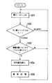
実施例は以上の構成からなり、その作用を図5及び図2を参照しながら説明する。図3に示されるように、アダプタユニットとしてのハイビジョン方式変換器22の取付けは、プロセッサ装置15の専用スロット25に挿入し、固定ネジ31を挿入孔32からネジ孔28へ結合させることにより行われる。図5において、上述したハイビジョン方式変換器22の挿入・ネジ止め(ステップ101)が行われると、ステップ102では、ネジ部検出スイッチSW1がオンされているか否かの判定が行われ、図2(B)のように、固定ネジ31によって検出スイッチSW1がオンされた[Y(YES)]ときは、次のステップ103にて、電源線コネクタ26B,30Bの結合によって電源線が通電状態になっているか否かが判定される。これは、電源線Sbに例えば5mAが流れる状態を検出することによって判定され、ここで、Yのときは、ステップ104にて信号線の活線化が実行され、その後に通常処理が行われる(ステップ105)。The embodiment has the above-described configuration, and its operation will be described with reference to FIGS. As shown in FIG. 3, the
即ち、図1に示されるように、DVI回路20の制御回路20Cは検出スイッチSW1からのオン信号を受け、かつ電源線コネクタ26Bにつながる電源線Sbに電流が流れたことを判定したとき、制御線C1で供給される制御信号によって活線処理回路36を動作させ、信号線Saを活線状態に設定する。一方、ハイビジョン方式変換器22の取外しにおいては、まず図2(A)に示されるように、固定ネジ31が外されるので、検出スイッチSW1はオフ状態となり、この結果、電源線コネクタ26B,30Bが外れる前に、信号線Saは活線処理回路36によって非活線化される。このようにして、電源線Sbによる電源の供給と、信号線Saによる信号の伝送が時間差を持って電気的に導通状態又は非導通状態となるので、DVI回路20やハイビジョン方式変換器22の内部回路に影響を与えることなく、ハイビジョン方式変換器22の取付け・取外しが容易に行われる。That is, as shown in FIG. 1, when it is determined that the
そして、ハイビジョン方式変換器22を取り付けていないときは、専用スロット25内は空となるので、このスロット25の入口に別途用意した板状の蓋を固定ネジ31で固定することが好ましいが、この場合でも、固定ネジ31の取付けのみでは、信号線Saは活線状態とはならない。従って、信号線コネクタ26Aのピン等がアンテナとなって不要電磁波ノイズを輻射させることも有効に防止される。 When the high-
なお、このハイビジョン方式変換器22によれば、パソコン用モニタを出力対象として形成された例えば640×480(VGA)、1024×768(XGA)、1280×960、1280×1024(SXGA)等の表示規格の映像信号をハイビジョンテレビ信号に変換し、この映像信号をハイビジョン用モニタやハイビジョン用レコーダに出力することができ、内視鏡で得られた被観察体をハイビジョン映像で観察することが可能になる。 According to the high-
また、実施例では、ハイビジョン方式変換器22をプロセッサ装置15へ接続する場合を説明したが、その他の機能を持つアダプタユニットをプロセッサ装置15へ着脱可能に接続する場合にも適用することができる。 In the embodiment, the case where the
10…電子内視鏡、 15…プロセッサ装置、
17…DSP、 19…マイコン、
20…DVI回路(差動信号出力部)、
20C…制御回路、
22…ハイビジョン方式変換器、
26A,30A…信号線コネクタ、
26B,30B…電源線コネクタ、
36…活線処理回路、
Sa…信号線、 Sb…電源線、
SW1…検出スイッチ。10 ... Electronic endoscope, 15 ... Processor device,
17 ... DSP, 19 ... Microcomputer,
20 ... DVI circuit (differential signal output unit),
20C ... control circuit,
22 ... Hi-Vision converter
26A, 30A ... signal line connector,
26B, 30B ... power line connector,
36 ... hot-wire processing circuit,
Sa ... signal line, Sb ... power line,
SW1 ... detection switch.
Claims (2)
Translated fromJapaneseこの電子内視鏡から入力した映像信号に対し各種の映像処理を施すプロセッサ装置と、
このプロセッサ装置のコネクタ部に接続しかつ固定具によって固定するように構成され、所定の信号処理を実行するアダプタユニットと、
このアダプタユニットが上記固定具で上記プロセッサ装置へ固定されているか否かを検出する固定状態検出手段と、
上記プロセッサ装置のコネクタ部における信号線の活線/非活線を設定する活線処理回路と、
上記固定状態検出手段の出力から上記アダプタユニットの固定状態が判定され、かつこのアダプタユニットのコネクタ接続の電源ラインが通電状態になっていると判定されたとき、上記活線処理回路によって上記プロセッサ装置のコネクタ部の信号線を活線化する制御回路と、からなる電子内視鏡装置。An electronic endoscope equipped with a solid-state imaging device for imaging an object to be observed;
A processor device for performing various types of video processing on video signals input from the electronic endoscope;
An adapter unit configured to connect to the connector portion of the processor device and to be fixed by a fixture, and to execute predetermined signal processing;
Fixed state detecting means for detecting whether or not the adapter unit is fixed to the processor device by the fixing tool;
A live line processing circuit for setting a live line / non-live line of a signal line in the connector portion of the processor device;
When the fixed state of the adapter unit is determined from the output of the fixed state detecting means, and when it is determined that the power line connected to the connector of the adapter unit is in an energized state, the processor device is processed by the hot wire processing circuit. An electronic endoscope apparatus comprising: a control circuit that activates a signal line of a connector portion of the electronic endoscope.
Priority Applications (2)
| Application Number | Priority Date | Filing Date | Title |
|---|---|---|---|
| JP2004018898AJP4426854B2 (en) | 2004-01-27 | 2004-01-27 | Electronic endoscope device |
| US11/038,262US7282025B2 (en) | 2004-01-27 | 2005-01-21 | Electronic endoscope apparatus for connection to adapter unit |
Applications Claiming Priority (1)
| Application Number | Priority Date | Filing Date | Title |
|---|---|---|---|
| JP2004018898AJP4426854B2 (en) | 2004-01-27 | 2004-01-27 | Electronic endoscope device |
Publications (2)
| Publication Number | Publication Date |
|---|---|
| JP2005211160A JP2005211160A (en) | 2005-08-11 |
| JP4426854B2true JP4426854B2 (en) | 2010-03-03 |
Family
ID=34792559
Family Applications (1)
| Application Number | Title | Priority Date | Filing Date |
|---|---|---|---|
| JP2004018898AExpired - Fee RelatedJP4426854B2 (en) | 2004-01-27 | 2004-01-27 | Electronic endoscope device |
Country Status (2)
| Country | Link |
|---|---|
| US (1) | US7282025B2 (en) |
| JP (1) | JP4426854B2 (en) |
Families Citing this family (47)
| Publication number | Priority date | Publication date | Assignee | Title |
|---|---|---|---|---|
| US7895384B2 (en)* | 2004-05-10 | 2011-02-22 | Sony Computer Entertainment Inc. | Portable terminal and USB device |
| JP2006015131A (en)* | 2004-06-02 | 2006-01-19 | Pentax Corp | Electronic endoscope system |
| JP4885706B2 (en)* | 2006-12-28 | 2012-02-29 | 富士通株式会社 | Power supply monitoring and control device for display device |
| JP2009015041A (en)* | 2007-07-05 | 2009-01-22 | Fuji Xerox Co Ltd | Reception module and signal transmitter using it |
| JP2009022689A (en)* | 2007-07-24 | 2009-02-05 | Hoya Corp | Electronic endoscope apparatus |
| EP2241922B1 (en)* | 2007-10-30 | 2012-02-22 | Olympus Corporation | Endoscope apparatus |
| JP5132419B2 (en)* | 2008-05-20 | 2013-01-30 | 富士フイルム株式会社 | Endoscope system and option board |
| US9901244B2 (en) | 2009-06-18 | 2018-02-27 | Endochoice, Inc. | Circuit board assembly of a multiple viewing elements endoscope |
| US9492063B2 (en) | 2009-06-18 | 2016-11-15 | Endochoice Innovation Center Ltd. | Multi-viewing element endoscope |
| US12137873B2 (en) | 2009-06-18 | 2024-11-12 | Endochoice, Inc. | Compact multi-viewing element endoscope system |
| US9402533B2 (en) | 2011-03-07 | 2016-08-02 | Endochoice Innovation Center Ltd. | Endoscope circuit board assembly |
| US9642513B2 (en) | 2009-06-18 | 2017-05-09 | Endochoice Inc. | Compact multi-viewing element endoscope system |
| US9713417B2 (en) | 2009-06-18 | 2017-07-25 | Endochoice, Inc. | Image capture assembly for use in a multi-viewing elements endoscope |
| US9101287B2 (en) | 2011-03-07 | 2015-08-11 | Endochoice Innovation Center Ltd. | Multi camera endoscope assembly having multiple working channels |
| US10165929B2 (en) | 2009-06-18 | 2019-01-01 | Endochoice, Inc. | Compact multi-viewing element endoscope system |
| US9101268B2 (en) | 2009-06-18 | 2015-08-11 | Endochoice Innovation Center Ltd. | Multi-camera endoscope |
| US11547275B2 (en) | 2009-06-18 | 2023-01-10 | Endochoice, Inc. | Compact multi-viewing element endoscope system |
| US11278190B2 (en) | 2009-06-18 | 2022-03-22 | Endochoice, Inc. | Multi-viewing element endoscope |
| WO2010146587A1 (en) | 2009-06-18 | 2010-12-23 | Peer Medical Ltd. | Multi-camera endoscope |
| US9872609B2 (en) | 2009-06-18 | 2018-01-23 | Endochoice Innovation Center Ltd. | Multi-camera endoscope |
| US11864734B2 (en) | 2009-06-18 | 2024-01-09 | Endochoice, Inc. | Multi-camera endoscope |
| US9706903B2 (en) | 2009-06-18 | 2017-07-18 | Endochoice, Inc. | Multiple viewing elements endoscope system with modular imaging units |
| US8926502B2 (en) | 2011-03-07 | 2015-01-06 | Endochoice, Inc. | Multi camera endoscope having a side service channel |
| US8648932B2 (en) | 2009-08-13 | 2014-02-11 | Olive Medical Corporation | System, apparatus and methods for providing a single use imaging device for sterile environments |
| WO2011120014A1 (en) | 2010-03-25 | 2011-09-29 | Olive Medical Corporation | System and method for providing a single use imaging device for medical applications |
| US12220105B2 (en) | 2010-06-16 | 2025-02-11 | Endochoice, Inc. | Circuit board assembly of a multiple viewing elements endoscope |
| EP2618718B1 (en) | 2010-09-20 | 2020-04-15 | EndoChoice Innovation Center Ltd. | Multi-camera endoscope having fluid channels |
| US9560953B2 (en) | 2010-09-20 | 2017-02-07 | Endochoice, Inc. | Operational interface in a multi-viewing element endoscope |
| CN103403605A (en) | 2010-10-28 | 2013-11-20 | 恩多巧爱思创新中心有限公司 | Optical systems for multi-sensor endoscopes |
| US12204087B2 (en) | 2010-10-28 | 2025-01-21 | Endochoice, Inc. | Optical systems for multi-sensor endoscopes |
| US11889986B2 (en) | 2010-12-09 | 2024-02-06 | Endochoice, Inc. | Flexible electronic circuit board for a multi-camera endoscope |
| CN107361721B (en) | 2010-12-09 | 2019-06-18 | 恩多巧爱思创新中心有限公司 | Flexible electronic circuit boards for multi-camera endoscopes |
| US9320419B2 (en) | 2010-12-09 | 2016-04-26 | Endochoice Innovation Center Ltd. | Fluid channeling component of a multi-camera endoscope |
| EP2672878B1 (en) | 2011-02-07 | 2017-11-22 | Endochoice Innovation Center Ltd. | Multi-element cover for a multi-camera endoscope |
| JP2012209849A (en)* | 2011-03-30 | 2012-10-25 | Toshiba Teli Corp | Rotating camera device |
| EP2708021B1 (en) | 2011-05-12 | 2019-07-10 | DePuy Synthes Products, Inc. | Image sensor with tolerance optimizing interconnects |
| CA2798716A1 (en) | 2011-12-13 | 2013-06-13 | Peermedical Ltd. | Removable tip endoscope |
| EP2604172B1 (en) | 2011-12-13 | 2015-08-12 | EndoChoice Innovation Center Ltd. | Rotatable connector for an endoscope |
| US9560954B2 (en) | 2012-07-24 | 2017-02-07 | Endochoice, Inc. | Connector for use with endoscope |
| US9462234B2 (en) | 2012-07-26 | 2016-10-04 | DePuy Synthes Products, Inc. | Camera system with minimal area monolithic CMOS image sensor |
| EP2967285B1 (en) | 2013-03-15 | 2023-08-16 | DePuy Synthes Products, Inc. | Image sensor synchronization without input clock and data transmission clock |
| CA2906975A1 (en) | 2013-03-15 | 2014-09-18 | Olive Medical Corporation | Minimize image sensor i/o and conductor counts in endoscope applications |
| US9986899B2 (en) | 2013-03-28 | 2018-06-05 | Endochoice, Inc. | Manifold for a multiple viewing elements endoscope |
| US9993142B2 (en) | 2013-03-28 | 2018-06-12 | Endochoice, Inc. | Fluid distribution device for a multiple viewing elements endoscope |
| US10499794B2 (en) | 2013-05-09 | 2019-12-10 | Endochoice, Inc. | Operational interface in a multi-viewing element endoscope |
| DE102018111645B4 (en)* | 2018-05-15 | 2024-01-11 | Schölly Fiberoptic GmbH | Image recording arrangement, associated use and method for putting an image recording arrangement into operation |
| US11923642B2 (en)* | 2021-02-10 | 2024-03-05 | Juniper Networks, Inc. | Apparatus, system, and method for protecting power connectors against high-power arcing |
Family Cites Families (7)
| Publication number | Priority date | Publication date | Assignee | Title |
|---|---|---|---|---|
| JPH04253830A (en) | 1991-02-05 | 1992-09-09 | Fuji Photo Optical Co Ltd | Electronic endoscope |
| US6184922B1 (en)* | 1997-07-31 | 2001-02-06 | Olympus Optical Co., Ltd. | Endoscopic imaging system in which still image-specific or motion picture-specific expansion unit can be coupled to digital video output terminal in freely uncoupled manner |
| JP3370916B2 (en)* | 1997-12-11 | 2003-01-27 | 富士写真光機株式会社 | An electronic endoscope device that displays a display without a scope |
| US6432041B1 (en)* | 1998-09-09 | 2002-08-13 | Olympus Optical Co., Ltd. | Endoscope shape detecting apparatus wherein form detecting processing is controlled according to connection state of magnetic field generating means |
| JP2002345745A (en)* | 2001-05-22 | 2002-12-03 | Olympus Optical Co Ltd | Endoscopic system |
| JP3939941B2 (en) | 2001-07-19 | 2007-07-04 | オリンパス株式会社 | Video signal processing system |
| US6945930B2 (en)* | 2001-08-31 | 2005-09-20 | Olympus Corporation | Environment adaptable measurement endoscope |
- 2004
- 2004-01-27JPJP2004018898Apatent/JP4426854B2/ennot_activeExpired - Fee Related
- 2005
- 2005-01-21USUS11/038,262patent/US7282025B2/ennot_activeExpired - Fee Related
Also Published As
| Publication number | Publication date |
|---|---|
| JP2005211160A (en) | 2005-08-11 |
| US20050165274A1 (en) | 2005-07-28 |
| US7282025B2 (en) | 2007-10-16 |
Similar Documents
| Publication | Publication Date | Title |
|---|---|---|
| JP4426854B2 (en) | Electronic endoscope device | |
| US7773110B2 (en) | Electronic endoscope apparatus | |
| CN100563333C (en) | endoscopic device | |
| JP2005130962A (en) | Electronic endoscope apparatus | |
| US7429242B2 (en) | Electronic endoscope apparatus and signal processing apparatus having detachable option substrate | |
| CN109310408A (en) | Endoscope system with multiple connection interfaces for connection to different video data signal sources | |
| JP2005211159A (en) | Electronic endoscope apparatus | |
| JP2005102764A (en) | Electronic endoscopic apparatus | |
| JP2001215419A (en) | Electronic endoscope device | |
| EP1500367B1 (en) | Image processing device and image pickup device | |
| JP5932191B1 (en) | Transmission system and processing device | |
| JP4459564B2 (en) | Endoscope system having an image signal processing device | |
| JP4493387B2 (en) | Electronic endoscope device | |
| JP2006000276A (en) | Camera head for endoscope, camera system for endoscope and endoscope system | |
| JP3175782B2 (en) | Endoscope device | |
| JP4370007B2 (en) | Endoscope device | |
| JP4398106B2 (en) | Image sensor driving unit and image pickup apparatus using the same | |
| JP4652681B2 (en) | Endoscopic imaging system | |
| JP4493390B2 (en) | Electronic endoscope device | |
| US20080100700A1 (en) | Electronic endoscope | |
| JPH05176882A (en) | Endoscope system | |
| JP2005021457A (en) | Endoscope system | |
| JP3944926B2 (en) | Camera device | |
| JP2005185358A (en) | Image signal processor, and endoscopic imaging system | |
| JP3147503B2 (en) | Adapter for drive of imaging means of electronic endoscope |
Legal Events
| Date | Code | Title | Description |
|---|---|---|---|
| A621 | Written request for application examination | Free format text:JAPANESE INTERMEDIATE CODE: A621 Effective date:20061011 | |
| A711 | Notification of change in applicant | Free format text:JAPANESE INTERMEDIATE CODE: A711 Effective date:20090902 | |
| RD02 | Notification of acceptance of power of attorney | Free format text:JAPANESE INTERMEDIATE CODE: A7422 Effective date:20090907 | |
| A977 | Report on retrieval | Free format text:JAPANESE INTERMEDIATE CODE: A971007 Effective date:20091130 | |
| TRDD | Decision of grant or rejection written | ||
| A01 | Written decision to grant a patent or to grant a registration (utility model) | Free format text:JAPANESE INTERMEDIATE CODE: A01 Effective date:20091208 | |
| A01 | Written decision to grant a patent or to grant a registration (utility model) | Free format text:JAPANESE INTERMEDIATE CODE: A01 | |
| A61 | First payment of annual fees (during grant procedure) | Free format text:JAPANESE INTERMEDIATE CODE: A61 Effective date:20091211 | |
| R150 | Certificate of patent or registration of utility model | Free format text:JAPANESE INTERMEDIATE CODE: R150 | |
| FPAY | Renewal fee payment (event date is renewal date of database) | Free format text:PAYMENT UNTIL: 20121218 Year of fee payment:3 | |
| LAPS | Cancellation because of no payment of annual fees |