JP4426737B2 - Refrigeration equipment for vehicles - Google Patents
Refrigeration equipment for vehiclesDownload PDFInfo
- Publication number
- JP4426737B2 JP4426737B2JP2001133494AJP2001133494AJP4426737B2JP 4426737 B2JP4426737 B2JP 4426737B2JP 2001133494 AJP2001133494 AJP 2001133494AJP 2001133494 AJP2001133494 AJP 2001133494AJP 4426737 B2JP4426737 B2JP 4426737B2
- Authority
- JP
- Japan
- Prior art keywords
- switch
- output
- generator
- storage battery
- battery unit
- Prior art date
- Legal status (The legal status is an assumption and is not a legal conclusion. Google has not performed a legal analysis and makes no representation as to the accuracy of the status listed.)
- Expired - Fee Related
Links
Images


Classifications
- B—PERFORMING OPERATIONS; TRANSPORTING
- B60—VEHICLES IN GENERAL
- B60H—ARRANGEMENTS OF HEATING, COOLING, VENTILATING OR OTHER AIR-TREATING DEVICES SPECIALLY ADAPTED FOR PASSENGER OR GOODS SPACES OF VEHICLES
- B60H1/00—Heating, cooling or ventilating [HVAC] devices
- B60H1/00642—Control systems or circuits; Control members or indication devices for heating, cooling or ventilating devices
- B60H1/00735—Control systems or circuits characterised by their input, i.e. by the detection, measurement or calculation of particular conditions, e.g. signal treatment, dynamic models
- B60H1/00764—Control systems or circuits characterised by their input, i.e. by the detection, measurement or calculation of particular conditions, e.g. signal treatment, dynamic models the input being a vehicle driving condition, e.g. speed
- B60H1/00778—Control systems or circuits characterised by their input, i.e. by the detection, measurement or calculation of particular conditions, e.g. signal treatment, dynamic models the input being a vehicle driving condition, e.g. speed the input being a stationary vehicle position, e.g. parking or stopping
- B—PERFORMING OPERATIONS; TRANSPORTING
- B60—VEHICLES IN GENERAL
- B60H—ARRANGEMENTS OF HEATING, COOLING, VENTILATING OR OTHER AIR-TREATING DEVICES SPECIALLY ADAPTED FOR PASSENGER OR GOODS SPACES OF VEHICLES
- B60H1/00—Heating, cooling or ventilating [HVAC] devices
- B60H1/00421—Driving arrangements for parts of a vehicle air-conditioning
- B60H1/00428—Driving arrangements for parts of a vehicle air-conditioning electric
- B—PERFORMING OPERATIONS; TRANSPORTING
- B60—VEHICLES IN GENERAL
- B60H—ARRANGEMENTS OF HEATING, COOLING, VENTILATING OR OTHER AIR-TREATING DEVICES SPECIALLY ADAPTED FOR PASSENGER OR GOODS SPACES OF VEHICLES
- B60H1/00—Heating, cooling or ventilating [HVAC] devices
- B60H1/32—Cooling devices
- B60H1/3204—Cooling devices using compression
- B60H1/3222—Cooling devices using compression characterised by the compressor driving arrangements, e.g. clutches, transmissions or multiple drives
- F—MECHANICAL ENGINEERING; LIGHTING; HEATING; WEAPONS; BLASTING
- F25—REFRIGERATION OR COOLING; COMBINED HEATING AND REFRIGERATION SYSTEMS; HEAT PUMP SYSTEMS; MANUFACTURE OR STORAGE OF ICE; LIQUEFACTION SOLIDIFICATION OF GASES
- F25B—REFRIGERATION MACHINES, PLANTS OR SYSTEMS; COMBINED HEATING AND REFRIGERATION SYSTEMS; HEAT PUMP SYSTEMS
- F25B27/00—Machines, plants or systems, using particular sources of energy
- F—MECHANICAL ENGINEERING; LIGHTING; HEATING; WEAPONS; BLASTING
- F25—REFRIGERATION OR COOLING; COMBINED HEATING AND REFRIGERATION SYSTEMS; HEAT PUMP SYSTEMS; MANUFACTURE OR STORAGE OF ICE; LIQUEFACTION SOLIDIFICATION OF GASES
- F25B—REFRIGERATION MACHINES, PLANTS OR SYSTEMS; COMBINED HEATING AND REFRIGERATION SYSTEMS; HEAT PUMP SYSTEMS
- F25B2327/00—Refrigeration system using an engine for driving a compressor
- F—MECHANICAL ENGINEERING; LIGHTING; HEATING; WEAPONS; BLASTING
- F25—REFRIGERATION OR COOLING; COMBINED HEATING AND REFRIGERATION SYSTEMS; HEAT PUMP SYSTEMS; MANUFACTURE OR STORAGE OF ICE; LIQUEFACTION SOLIDIFICATION OF GASES
- F25B—REFRIGERATION MACHINES, PLANTS OR SYSTEMS; COMBINED HEATING AND REFRIGERATION SYSTEMS; HEAT PUMP SYSTEMS
- F25B2600/00—Control issues
- F25B2600/02—Compressor control
- F25B2600/021—Inverters therefor
- F—MECHANICAL ENGINEERING; LIGHTING; HEATING; WEAPONS; BLASTING
- F25—REFRIGERATION OR COOLING; COMBINED HEATING AND REFRIGERATION SYSTEMS; HEAT PUMP SYSTEMS; MANUFACTURE OR STORAGE OF ICE; LIQUEFACTION SOLIDIFICATION OF GASES
- F25D—REFRIGERATORS; COLD ROOMS; ICE-BOXES; COOLING OR FREEZING APPARATUS NOT OTHERWISE PROVIDED FOR
- F25D11/00—Self-contained movable devices, e.g. domestic refrigerators
- F25D11/003—Transport containers
- F—MECHANICAL ENGINEERING; LIGHTING; HEATING; WEAPONS; BLASTING
- F25—REFRIGERATION OR COOLING; COMBINED HEATING AND REFRIGERATION SYSTEMS; HEAT PUMP SYSTEMS; MANUFACTURE OR STORAGE OF ICE; LIQUEFACTION SOLIDIFICATION OF GASES
- F25D—REFRIGERATORS; COLD ROOMS; ICE-BOXES; COOLING OR FREEZING APPARATUS NOT OTHERWISE PROVIDED FOR
- F25D29/00—Arrangement or mounting of control or safety devices
- F25D29/003—Arrangement or mounting of control or safety devices for movable devices
- Y—GENERAL TAGGING OF NEW TECHNOLOGICAL DEVELOPMENTS; GENERAL TAGGING OF CROSS-SECTIONAL TECHNOLOGIES SPANNING OVER SEVERAL SECTIONS OF THE IPC; TECHNICAL SUBJECTS COVERED BY FORMER USPC CROSS-REFERENCE ART COLLECTIONS [XRACs] AND DIGESTS
- Y02—TECHNOLOGIES OR APPLICATIONS FOR MITIGATION OR ADAPTATION AGAINST CLIMATE CHANGE
- Y02B—CLIMATE CHANGE MITIGATION TECHNOLOGIES RELATED TO BUILDINGS, e.g. HOUSING, HOUSE APPLIANCES OR RELATED END-USER APPLICATIONS
- Y02B40/00—Technologies aiming at improving the efficiency of home appliances, e.g. induction cooking or efficient technologies for refrigerators, freezers or dish washers
- Y—GENERAL TAGGING OF NEW TECHNOLOGICAL DEVELOPMENTS; GENERAL TAGGING OF CROSS-SECTIONAL TECHNOLOGIES SPANNING OVER SEVERAL SECTIONS OF THE IPC; TECHNICAL SUBJECTS COVERED BY FORMER USPC CROSS-REFERENCE ART COLLECTIONS [XRACs] AND DIGESTS
- Y02—TECHNOLOGIES OR APPLICATIONS FOR MITIGATION OR ADAPTATION AGAINST CLIMATE CHANGE
- Y02T—CLIMATE CHANGE MITIGATION TECHNOLOGIES RELATED TO TRANSPORTATION
- Y02T10/00—Road transport of goods or passengers
- Y02T10/80—Technologies aiming to reduce greenhouse gasses emissions common to all road transportation technologies
- Y02T10/88—Optimized components or subsystems, e.g. lighting, actively controlled glasses
Landscapes
- Engineering & Computer Science (AREA)
- Physics & Mathematics (AREA)
- Thermal Sciences (AREA)
- Mechanical Engineering (AREA)
- General Engineering & Computer Science (AREA)
- Devices That Are Associated With Refrigeration Equipment (AREA)
Description
Translated fromJapanese【0001】
【発明の属する技術分野】
この発明は、エンジンにより駆動される発電機を電源とする冷凍装置を搭載し、特に宅配便のように、頻繁に発停を繰り返す配送パターンで運用される冷凍車において、使い勝手と冷却性能を改善した、車両用冷凍装置に関する。
【0002】
【従来の技術】
発電式の車両用冷凍装置には、例えば特願平11−85993号に示されるように、電動圧縮機をインバータ駆動するための電源を、発電機、商用電源、蓄電池のいずれかから選択するようにするものがある。
【0003】
通常、発電機はエンジン走行中の通常冷却運転、商用電源は荷物積載時の予冷運転(スタンバイ運転)、蓄電池は配送中の停車時の保冷運転(アイドリングストップ運転)に、それぞれ使用される。冷凍車の運用上、発電機が主電源であり、商用電源および蓄電池は補助的要素が強い。
【0004】
これら電源の切換および冷凍装置全体の制御は制御器が行い、エンジンキースイッチオン、商用電源投入、アイドリングストップ運転スイッチオンのいずれかの操作で、上記各電源または車載バッテリから電源電圧が供給されて制御動作を開始するようにしている。また、エンジンキースイッチオフ、商用電源遮断、アイドリングストップ運転スイッチオフのいずれかの操作で、電源電圧の供給を遮断して制御器の動作を停止するようにしている。
【0005】
また、上記通常冷却運転、予冷運転、保冷運転のいずれかのモードで運転中に他のモード運転の開始操作が行われた場合には、制御器が優先順位を判断して冷凍装置の電源を切換えるが、各々の電源仕様が異なるため、一旦、電動圧縮機の運転を停止してからモード運転を切換えるようにしている。
【0006】
蓄電池は、体積、重量、コスト等の制約から出力仕様を控え目に設定するのが一般的である。発電機については、効率およびエンジン回転数昇降に伴う出力変動を考慮した最適な出力仕様で設計されるのが一般的である。例えば、発電機は三相220V(これが整流されて直流出力電圧285Vとなる)、商用電源は三相200V(これが整流されて直流出力電圧270Vとなる)、蓄電池はDC240Vというような仕様となる。
【0007】
【発明が解決しようとする課題】
上記のような車両用冷凍装置では、特に宅配便のように頻繁に発停を繰り返す配送パターンで運用される状況において、次のような問題を生じる。
【0008】
(1)宅配時等のエンジン停止に際してアイドリングストップ運転を実行するためには手動操作を行う必要があり、しかもその手動操作はエンジン停止ごとに必要となるため、使用者にとっては面倒であり大きな負担となる。また、操作し忘れによる庫内温度上昇、ひいては庫内の品温上昇が懸念される。
【0009】
(2)制御器の電源遮断時に、それまでの制御データを記憶素子(EEPROM等)に保存する場合、頻繁に電源遮断が発生すると、データ書込回数が多くなって記憶素子の寿命が短くなる。また、電源遮断までの時間的余裕がないため、保存しようとするデータ量が多い場合はその完全な保存が困難である。
【0010】
(3)上記(2)の不具合を補う手段として、車載バッテリ等から制御器へ動作用電圧を常時供給することが考えられるが、エンジン停止が長時間になると、車載バッテリの過放電や性能劣化等が懸念される。仮に、動作用電圧の供給を手動スイッチによってオン,オフするとしても、手動スイッチの切り忘れにより同様の問題が発生する。
【0011】
(4)電源遮断時または切換時に圧縮機が一旦停止してしまうため、冷凍サイクルにおける冷媒圧力をバランスさせるのに長い時間が必要となり、次回の再起動までに長い遅延時間を確保しなければならず、再起動しても所定の冷却能力が得られるまでには時間がかかってしまう。
【0012】
この発明は上記の事情を考慮したもので、その目的とするところは、エンジンの運転状況に影響を受けることなく、しかも使用者に負担をかけることなく、常に適切な運転を可能として庫内温度上昇などの不具合を解消し得る信頼性にすぐれた車両用冷凍装置を提供することにある。
【0013】
また、この発明は、制御データの確実な保存、制御データの記憶手段の寿命向上、次回再起動までの運転中断時間の解消、次回再起動時の冷却能力の立ち上がりの迅速化およびそれに伴う冷却効率の向上などが図れる車両用冷凍装置を提供することを目的とする。
【0014】
【課題を解決するための手段】
請求項1に係る発明の車両用冷凍装置は、車両用エンジンによって駆動される発電機と、発電機の出力によって充電される蓄電池ユニットと、発電機または蓄電池の出力を交流に変換するスイッチング回路と、このスイッチング回路の出力により駆動される圧縮機と、この圧縮機により冷媒か循環させられる冷凍サイクルを有する冷凍機と、上記圧縮機の電源の供給元を発電機または蓄電池ユニットのいずれかに切換える制御器と、蓄電式の電源から上記制御器に電源供給する制御器用電源とを備え、上記発電機、商用電源または蓄電池ユニットのいずれかの電源により圧縮機を駆動して冷凍または冷蔵を行うものであって、上記車両用エンジンの停止または上記蓄電池ユニットによる運転の停止後も上記制御器用電源から上記制御器への電源供給を継続する制御器電源保持手段と、上記車両用エンジンの停止または上記蓄電池ユニットによる運転の停止後、所定時間後に上記制御器電源保持手段を制御して上記制御器用電源から上記制御器への電源供給を遮断する電源遮断手段と、を備えている。
【0015】
請求項2に係る発明の車両用冷凍装置は、車両用エンジンによって駆動される発電機と、商用電源の入力端子と、発電機または商用電源入力によって充電される蓄電池ユニットと、発電機、商用電源または蓄電池の出力を交流に変換するスイヅチング回路と、このスイッチング回路の出力により駆動される圧縮機と、この圧縮機により冷媒が循環させられる冷凍サイクルを有する冷凍機と、上記圧縮機の電源の供給元を発電機、商用電源、または蓄電池ユニットのいずれかに切換える制御器と、商用電源または蓄電式の電源のいずれかから上記制御器に電源供給する制御器用電源とを備え、上記発電機、商用電源または蓄電池ユニットのいずれかの電源により圧縮機を駆動して冷凍または冷蔵を行うものであって、上記車両用エンジンの停止、上記商用電源または上記蓄電池ユニットによる運転の停止後も上記制御器用電源から上記制御器への電源供給を継続する制御器電源保持手段と、上記車両用エンジンの停止、上記商用電源または上記蓄電池ユニットによる運転の停止後、所定時間後に上記制御器電源保持手段を制御して上記制御器用電源から上記制御器への電源供給を遮断する電源遮断手段と、を備えている。
【0016】
請求項3に係る発明の車両用冷凍装置は、請求項1または請求項2に係る発明において、制御器について限定している。制御器は、制御データを電源供給なしに記憶保持する記憶手段を備えるとともに、自己保持を終了する直前に、それまでの制御データを上記記憶手段に記憶する記憶制御手段を有する。
【0017】
請求項4に係る発明の車両用冷凍装置は、請求項1ないし請求項3のいずれかに係る発明において、制御器について限定している。制御器は、さらに、自己保持中に、冷凍サイクルにおける冷媒圧力をバランスさせるための圧力バランス制御を実行する制御手段を有する。
【0018】
請求項5に係る発明の車両用冷凍装置は、車両用エンジンにより駆動される発電機と、この発電機の出力または商用電源からの入力を整流する整流回路と、この整流回路の出力により充電される蓄電池ユニットと、上記整流回路の出力または上記蓄電池ユニットの放電出力を交流に変換するスイッチング回路と、このスイッチング回路の出力により駆動される圧縮機と、上記発電機から上記整流回路への通電路に設けられた第1開閉器と、上記商用電源から上記整流回路への通電路に設けられた第2開閉器と、上記蓄電池ユニットから上記スイッチング回路への放電路に設けられた第3開閉器と、上記エンジンの運転と停止を切換設定する操作スイッチと、上記発電機の出力の有無および上記商用電源からの入力の有無を検出する検出手段と、この検出手段の検出結果に応じて上記第1開閉器、第2開閉器、第3開閉器を選択的に閉成するとともに、負荷に応じて上記スイッチング回路の駆動および出力周波数を制御する制御手段を有し、かつ上記操作スイッチのオン時にその操作スイッチを通して制御器用電源から電力を受けることにより動作し、同操作スイッチのオフから所定時間にわたり制御器用電源により電源供給を受け動作状態を自己保持する制御手段を有する制御器と、を備えている。
【0019】
請求項6に係る発明の車両用冷凍装置は、車両用エンジンにより駆動される発電機と、この発電機の出力または商用電源からの入力を整流する整流回路と、この整流回路の出力により充電される蓄電池ユニットと、上記整流回路の出力または上記蓄電池ユニットの放電出力を交流に変換するスイッチング回路と、このスイッチング回路の出力により駆動される圧縮機と、上記発電機から上記整流回路への通電路に設けられた第1開閉器と、上記商用電源から上記整流回路への通電路に設けられた第2開閉器と、上記蓄電池ユニットから上記スイッチング回路への放電路に設けられた第3開閉器と、上記エンジンの運転と停止を切換設定する第1操作スイッチと、上記エンジンが停止しているときの車両用冷凍装置の運転と停止を切換設定するための第2操作スイッチと、上記発電機の出力の有無および上記商用電源からの入力の有無を検出する検出手段と、この検出手段の検出結果および上記第2操作スイッチの操作状態に応じて上記第1開閉器、第2開閉器、第3開閉器を選択的に閉成するとともに、負荷に応じて上記スイッチング回路の駆動および出力周波数を制御する制御手段を有し、かつ上記第1操作スイッチまたは上記第2操作スイッチのオン時にその操作スイッチを通して制御器用電源から電力を受けることにより動作し、その電力の受給およびそれに基づく動作状態を同操作スイッチのオフから所定時間にわたり自己保持する制御手段を有する制御器と、を備えている。
【0020】
請求項7に係る発明の車両用冷凍装置は、請求項5または請求項6に係る発明において、制御器について限定している。制御器は、さらに、操作スイッチがオフになる前に使用していた電源が発電機、商用電源、蓄電池ユニットのいずれかであるかを判定しその判定結果に応じて自己保持の時間を可変設定する制御手段を有する。
【0021】
請求項8に係る発明の車両用冷凍装置は、請求項5ないし請求項7に係る発明のいずれかにおいて、制御器について限定している。制御器は、さらに、制御データを電源供給なしに記憶保持する記憶手段を備え、自己保持を終了する直前に、それまでの制御データを上記記憶手段に記憶する制御手段を有している。
【0022】
請求項9に係る発明の車両用冷凍装置は、請求項5ないし請求項7に係る発明のいずれかにおいて、さらに、上記圧縮機から吐出される冷媒が循環する冷凍サイクルを備えている。そして、制御器は、さらに、自己保持中に、上記冷凍サイクルにおける冷媒圧力をバランスさせるための圧力バランス制御を実行する制御手段を有している。
【0023】
請求項10に係る発明の車両用冷凍装置は、請求項1、請求項2、請求項5、および請求項6に係る発明のいずれかにおいて、制御器電源が車載バッテリであることを限定している。
【0024】
請求項11に係る発明の車両用冷凍装置は、請求項1、請求項2、請求項5、および請求項6に係る発明のいずれかにおいて、制御器用電源が蓄電池ユニットの兼用であることを限定している。
【0025】
請求項12に係る発明の車両用冷凍装置は、請求項2または請求項6に係る発明において、制御器用電源について限定している。制御器用電源は、車載バッテリまたは蓄電池ユニットから電源供給され、商用電源の入力があるときには、商用電源から電源供給される。
【0026】
請求項13に係る発明の車両用冷凍装置は、車両用エンジンにより駆動される発電機と、この発電機の出力または商用電源からの入力を整流する整流回路と、この整流回路の出力により充電される蓄電池ユニットと、上記整流回路の出力または上記蓄電池ユニットの放電出力を交流に変換するスイッチング回路と、このスイッチング回路の出力により駆動される圧縮機と、上記発電機から上記整流回路への通電路に設けられた第1開閉器と、上記商用電源から上記整流回路への通電路に設けられた第2開閉器と、上記蓄電池ユニットから上記スイッチング回路への放電路に設けられた第3開閉器と、上記エンジンの運転と停止を切換設定する操作スイッチと、上記発電機の出力の有無および上記商用電源からの入力の有無を検出する検出手段と、この検出手段の検出結果に応じて上記第1開閉器、第2開閉器、第3開閉器を選択的に閉成するとともに、負荷に応じて上記スイッチング回路の駆動および出力周波数を制御し、各開閉器の閉成切換時にスイッチング回路の駆動を継続する制御手段と、を備えている。
【0027】
請求項14に係る発明の車両用冷凍装置は、車両用エンジンにより駆動される発電機と、この発電機の出力または商用電源からの入力を整流する整流回路と、この整流回路の出力により充電される蓄電池ユニットと、上記整流回路の出力または上記蓄電池ユニットの放電出力を交流に変換するスイッチング回路と、このスイッチング回路の出力により駆動される圧縮機と、上記発電機から上記整流回路への通電路に設けられた第1開閉器と、上記商用電源から上記整流回路への通電路に設けられた第2開閉器と、上記蓄電池ユニットから上記スイッチング回路への放電路に設けられた第3開閉器と、上記エンジンの運転と停止を切換設定する第1操作スイッチと、上記エンジンが停止しているときの車両用冷凍装置の運転と停止を切換設定するための第2操作スイッチと、上記発電機の出力の有無および上記商用電源からの入力の有無を検出する検出手段と、この検出手段の検出結果に応じて上記第1開閉器、第2開閉器、第3開閉器を選択的に閉成するとともに、負荷に応じて上記スイッチング回路の駆動および出力周波数を制御し、各開閉器の閉成切換時にスイッチング回路の駆動を継続する制御手段と、を備えている。
【0028】
請求項15に係る発明の車両用冷凍装置は、請求項13または請求項14に係る発明において、制御手段について限定している。制御手段は、各開閉器の閉成切換時にスイッチング回路の駆動を継続するとともにそのスイッチング回路の出力周波数を所定値まで低下させる。
【0029】
請求項16に係る発明の車両用冷凍装置は、請求項13ないし請求項15に係る発明のいずれかにおいて、制御手段について限定している。制御手段は、エンジン停止後、圧縮機への電源供給元を発電機から蓄電池ユニットに切換える時にスイッチング回路の駆動を継続するとともにそのスイッチング回路の出力周波数を通常運転時より速い速度で所定値まで低下させる。
【0030】
請求項17に係る発明の車両用冷凍装置は、請求項13ないし請求項16に係る発明のいずれかにおいて、制御手段について限定している。制御手段は、各開閉器の選択的な閉成に伴ってスイッチング回路の出力電圧/出力周波数パターンを切換えるとともに、その切換時にスイッチング回路の出力電圧を所定値まで段階的に低下させ且つ出力周波数を所定値に固定する。
【0031】
請求項18に係る発明の車両用冷凍装置は、車両用エンジンにより駆動される発電機と、この発電機の出力または商用電源からの入力を整流する整流回路と、この整流回路の出力により充電される蓄電池ユニットと、上記整流回路の出力または上記蓄電池ユニットの放電出力を交流に変換するスイッチング回路と、このスイッチング回路の出力により駆動される圧縮機と、上記発電機から上記整流回路への通電路に設けられた第1開閉器と、上記商用電源から上記整流回路への通電路に設けられた第2開閉器と、上記蓄電池ユニットから上記スイッチング回路への放電路に設けられた第3開閉器と、上記エンジンの運転と停止を切換設定する操作スイッチと、上記発電機の出力の有無および上記商用電源からの入力の有無を検出する検出手段と、この検出手段の検出結果に応じて上記第1開閉器、第2開閉器、第3開閉器を選択的に閉成するとともに、負荷に応じて上記スイッチング回路の駆動および出力周波数を制御する制御手段とを備えている。この制御手段は、商用電源または蓄電池ユニットによる電源供給時よりも、発電機による電源供給時のスイッチング回路の出力周波数の変化速度を速くする。
【0032】
請求項19に係る発明の車両用冷凍装置は、車両用エンジンにより駆動される発電機と、この発電機の出力または商用電源からの入力を整流する整流回路と、この整流回路の出力により充電される蓄電池ユニットと、上記整流回路の出力または上記蓄電池ユニットの放電出力を交流に変換するスイッチング回路と、このスイッチング回路の出力により駆動される圧縮機と、上記発電機から上記整流回路への通電路に設けられた第1開閉器と、上記商用電源から上記整流回路への通電路に設けられた第2開閉器と、上記蓄電池ユニットから上記スイッチング回路への放電路に設けられた第3開閉器と、上記エンジンの運転と停止を切換設定する第1操作スイッチと、上記エンジンが停止しているときの車両用冷凍装置の運転と停止を切換設定するための第2操作スイッチと、上記発電機の出力の有無および上記商用電源からの入力の有無を検出する検出手段と、この検出手段の検出結果および上記第2操作スイッチの操作状態に応じて上記第1開閉器、第2開閉器、第3開閉器を選択的に閉成するとともに、負荷に応じて上記スイッチング回路の駆動および出力周波数を制御する制御手段とを備えている。この制御手段は、商用電源または蓄電池ユニットによる電源供給時よりも、発電機による電源供給時のスイッチング回路の出力周波数の変化速度を速くする。
【0033】
請求項20に係る発明の車両用冷凍装置は、車両用エンジンにより駆動される発電機と、この発電機の出力または商用電源からの入力を整流する整流回路と、この整流回路の出力により充電される蓄電池ユニットと、上記整流回路の出力または上記蓄電池ユニットの放電出力を交流に変換するスイッチング回路と、このスイッチング回路の出力により駆動される圧縮機と、上記発電機から上記整流回路への通電路に設けられた第1開閉器と、上記商用電源から上記整流回路への通電路に設けられた第2開閉器と、上記蓄電池ユニットから上記スイッチング回路への放電路に設けられた第3開閉器と、上記エンジンの運転と停止を切換設定する操作スイッチと、上記発電機の出力の有無および上記商用電源からの入力の有無を検出する検出手段と、この検出手段の検出結果に応じて上記第1開閉器、第2開閉器、第3開閉器を選択的に閉成するとともに、負荷に応じて上記スイッチング回路の駆動および出力周波数を制御する制御手段と、上記蓄電池ユニットに対する充電専用モードを設定するための操作手段を備えている。上記制御手段は、上記第1開閉器または上記第2開閉器の閉成時、上記充電専用モードが設定された場合に、上記スイッチング回路を駆動しない。
【0034】
請求項21に係る発明の車両用冷凍装置は、車両用エンジンにより駆動される発電機と、この発電機の出力または商用電源からの入力を整流する整流回路と、この整流回路の出力により充電される蓄電池ユニットと、上記整流回路の出力または上記蓄電池ユニットの放電出力を交流に変換するスイッチング回路と、このスイッチング回路の出力により駆動される圧縮機と、上記発電機から上記整流回路への通電路に設けられた第1開閉器と、上記商用電源から上記整流回路への通電路に設けられた第2開閉器と、上記蓄電池ユニットから上記スイッチング回路への放電路に設けられた第3開閉器と、上記エンジンの運転と停止を切換設定する第1操作スイッチと、上記エンジンが停止しているときの車両用冷凍装置の運転と停止を切換設定するための第2操作スイッチと、上記発電機の出力の有無および上記商用電源からの入力の有無を検出する検出手段と、この検出手段の検出結果および上記第2操作スイッチの操作状態に応じて上記第1開閉器、第2開閉器、第3開閉器を選択的に閉成するとともに、負荷に応じて上記スイッチング回路の駆動および出力周波数を制御する制御手段とを備えている。さらに、上記蓄電池ユニットに対する充電専用モードを設定するための操作手段を備えている。上記制御手段は、上記第1開閉器または上記第2開閉器の閉成時、上記充電専用モードが設定された場合に、上記スイッチング回路を駆動しない。
【0035】
【発明の実施の形態】
[1]以下、この発明の第1の実施形態について図面を参照して説明する。
図1に示すように、冷凍車の動力源である車両用エンジン1にベルト等を介して発電機2が連結されている。発電機2は、車両用エンジン1の動力により機械的に駆動され、交流電力(例えば三相220V電圧)を発生する。この発電機2の出力端にインバータ回路10が接続され、その発電機2とインバータ回路10との間の通電路に電磁開閉器(第1開閉器)3が設けられている。
【0036】
外部電源であるところの商用電源4(いわゆる市中電源設備)は、所定の場所での利用が可能となっている。この商用電源4に対する接続・切離が自在な接続用端子Xが用意され、その接続用端子Xに上記インバータ回路10が接続され、その接続用端子Xとインバータ回路10との間の通電路に電磁開閉器(第2開閉器)5が設けられている。
【0037】
インバータ回路10は、発電機2の出力または商用電源4からの入力を整流する整流回路11を備え、この整流回路11の出力端に突入電流抑制回路12を介してスイッチング回路13を接続している。整流回路11の出力端には、上記突入電流抑制回路12を介して蓄電池ユニット30も接続されている。
【0038】
蓄電池ユニット30は、整流回路11の出力電圧を逆流防止用のダイオード31および充電回路32を介して蓄電池(蓄電式の電源)33に充電するとともに、その蓄電池33の電圧(例えばDC240V)を逆流防止用のダイオード34を介して放電出力する。この放電出力は上記突入電流抑制回路12を介してスイッチング回路13に供給されるようになっており、その放電路に放電リレー接点(第3開閉器)6が設けられている。
【0039】
スイッチング回路13は、後述するシステム制御器50の指令に応動じて複数のスイッチング素子をオン,オフすることにより、整流回路11の出力または蓄電池ユニット30の放電出力を所望の周波数の交流電力に変換する。このスイッチング回路13の出力端に冷凍機20における電動圧縮機21のモータ21Mが接続されている。
【0040】
冷凍機21は、圧縮機21から吐出される冷媒を室外熱交換器(凝縮器)22、減圧器たとえば膨張弁23、および庫内熱交換器(蒸発器)24を通して循環させる冷凍サイクルを備え、庫内熱交換器24により冷凍車の庫内空気を冷却する。
【0041】
一方、商用電源4の接続用端子Xに、商用電源4の交流電圧を所定レベルの直流電圧に変換するAC/DCコンバータ7が接続されている。このAC/DCコンバータ7は、システム制御器50に対する動作用電圧を出力するもので、制御器用電源として機能する。
【0042】
発電機2に自動電圧調整器(AVR)8が接続されている。自動電圧調整器8は、モータ21の回転数変化(負荷変動)にかかわらず、発電機2の出力電圧を一定値(例えば三相220V)に調整する。この自動電圧調整器8はシステム制御器50に信号線接続されている。
【0043】
冷凍車の車載バッテリ(蓄電式の電源)40に、エンジンキースイッチスイッチ(第1操作スイッチ)41、アイドリングストップ運転スイッチ(第2操作スイッチ)42、および保持リレー接点(常開接点)43をそれぞれ介してシステム制御器50が接続されている。車載バッテリ40は、本来は冷凍車の電気系統の電源であるが、システム制御器50に対して動作用電圧を供給するための制御器用電源としても兼用される。エンジンキースイッチ41は、上記エンジン1の運転と停止を切換設定するための手動スイッチである。アイドリングストップ運転スイッチ42は、エンジン1が停止し、かつ商用電源4の接続がないときの蓄電池ユニット30による冷凍機20の運転と停止を切換設定するための押釦スイッチ(自動復帰形の常開接点)である。
【0044】
システム制御器50に、庫内温度を検知する庫内温度センサ51およびコントローラ52が接続されている。コントローラ52は、操作部および表示部を有する。操作部には、後述の自動運転の有効・無効を切り換えるための自動運転入切スイッチが設けられている。
【0045】
本実施形態の運転モードとしては、エンジン運転に基づく発電機2の出力による発電機モードの運転、商用電源4の接続に基づく商用モードの運転、この発電機モードまたは商用モードの後で蓄電池ユニット30の放電による運転を所定時間だけ自動的に継続する自動運転、発電機2の出力が無く且つ商用電源4の接続がない場合にアイドリングストップ運転スイッチ42の押圧操作に応じて所定時間だけ行うアイドリングストップモードの運転がある。なお、自動運転は、コントローラ52の操作部における自動運転入切スイッチの操作に応じて有効と無効を選択することができる。
【0046】
そして、システム制御器50は、主要な機能として次の(1)〜(10)を有する。
【0047】
(1)エンジンキースイッチ41のオン,オフを検出し、自動電圧調整器8を介して発電機2の出力の有無を検出し、アイドリングストップ運転スイッチ42の押圧操作を検出し、かつAC/DCコンバータ7の出力に基づいて商用電源4からの入力の有無を検出する検出手段。
【0048】
(2)上記検出手段の検出結果(発電機2の出力の有無、商用電源4の入力の有無、アイドリングストップ運転スイッチ42の押圧操作)に応じて電磁開閉器3,5および放電リレー接点6を選択的に閉成するとともに、負荷に応じてスイッチング回路13の駆動および出力周波数を制御する制御手段。
具体的には、この制御手段は、エンジンキースイッチ41がオンで発電機2の出力が有り、商用電源4の入力は無い場合、電磁開閉器3を閉成して電磁開閉器5および放電リレー接点6を開放する機能Aと、
エンジンキースイッチ41がオンで発電機2の出力が有り、商用電源4の入力も有る場合、商用電源4を優先として、電磁開閉器5を閉成して電磁開閉器3および放電リレー接点6を開放する機能Bと、
エンジンキースイッチ41がオフで発電機2の出力が無く、商用電源4の入力は有る場合、電磁開閉器5を閉成して電磁開閉器3および放電リレー接点6を開放する機能Cと、
エンジンキースイッチ41がオフで発電機2の出力が無く、商用電源4の入力も無い場合、アイドリングストップ運転スイッチ42の押圧操作に応じて、放電リレー接点6を閉成し電磁開閉器3,5を開放する機能Dと、を備えている。
なお、機能Aでは、電磁開閉器3を閉成して電磁開閉器5および放電リレー接点6を開放するが、制御プログラムの設定変更により電磁開閉器3と放電リレー接点6を閉成して電磁開閉器5を開放してもよく、そうすることにより、発電機2からスイッチング回路13への電力供給と同時に蓄電池33を充電できるとともに、エンジン1の回転数が低くて発電機2の出力が低下した場合の供給電圧不足を蓄電池33の放電による補助的な電源供給によって補うことができる。また、機能Bでは、発電機2の出力が有って、しかも商用電源4の入力が有る場合に、商用電源4を優先するようにしているが、発電機2を優先することも、制御プログラムの設定変更により可能である。
【0049】
(3)エンジンキースイッチ41のオン時にそのエンジンキースイッチ41を通して車載バッテリ40から電源供給を受けることにより動作し、または商用電源4の接続時にAC/DCコンバータ7から電源供給を受けることにより動作し、その電源受給およびそれに基づく動作状態を、エンジンキースイッチ41のオフ後も、保持リレー接点43をオンして自己保持する第1の制御器電源保持手段。
【0050】
(4)上記エンジンキースイッチ41のオフによる車両用エンジン1の停止後、または商用電源4の切離しによるAC/DCコンバータ7の出力停止後、第1の所定時間にわたり、放電用リレー接点6をオンして蓄電池ユニット30の放電による自動運転(機能E)を実行する制御手段。
【0051】
(5)上記エンジンキースイッチ41のオフによる車両用エンジン1の停止後、または商用電源4の切離しによるAC/DCコンバータ7の出力停止後、第1の所定時間が経過して(自動運転が終了)、さらに第2の所定時間が経過したとき、保持リレー接点43をオフして自己保持を終了し、車載バッテリ40から当該システム制御器50への電源供給を遮断する第1の電源遮断手段。
【0052】
(6)エンジンキースイッチ41からの電力の受給およびAC/DCコンバータ7からの電力の受給のどちらも無い場合、アイドリングストップ運転スイッチ42が押圧操作(オン)されると、そのアイドリングストップ運転スイッチ42を通して車載バッテリ40から電力を受けることにより動作し、その電力の受給およびそれに基づく動作状態を、アイドリングストップ運転スイッチ42の復帰(オフ)にかかわらず、保持リレー接点43のオンによって自己保持する第2の制御器電源保持手段。
【0053】
(7)上記アイドリングストップ運転スイッチ42が押圧操作後、第3の所定時間にわたり、放電用リレー接点6をオンして蓄電池ユニット30の放電によるアイドリングストップモードの運転を実行する制御手段。
【0054】
(8)上記第3の所定時間が経過して(アイドリングストップモードの運転が終了)、さらに第4の所定時間が経過したとき、保持リレー接点43をオフして自己保持を終了し、車載バッテリ40から当該システム制御器50への電源供給を遮断する第2の電源遮断手段。
【0055】
(9)上記自己保持を終了する直前に、それまでの制御データを内部の記憶素子たとえばメモリ(EEPROM)53に記憶する制御手段。
【0056】
(10)上記自己保持中に、前記冷凍サイクルにおける冷媒圧力をバランスさせるための圧力バランス制御を実行する制御手段。
【0057】
(11)コントローラ52の操作部における自動運転入切スイッチの操作に応じて自動運転の有効と無効を選択する手段。
【0058】
つぎに、上記の構成の作用を説明する。
(a)まず、基本動作について説明する。
エンジンキースイッチ41がオンされると、エンジン1が始動して発電機2の運転が可能となる。同時に、車載バッテリ40の電圧(例えばDC24V)がエンジンキースイッチ41を通してシステム制御器50に供給され、システム制御器50が起動する。
【0059】
コントローラ52で運転開始の操作(運転スイッチオン)がなされると、システム制御器50は、自動電圧調整器8に運転指令を送信する。これにより、発電機2の運転が開始され、その開始を表わす信号が自動電圧調整器8からシステム制御器50に返信される。システム制御器50は、この返信により、発電機2の運転が開始されたことを察知して電磁開閉器3をオンする。
【0060】
電磁開閉器3がオンすると、発電機2の出力がインバータ回路10に供給される。この電力供給により、圧縮機21の駆動が可能になるとともに、蓄電池ユニット30の充電が開始される。
【0061】
庫内温度センサ51で庫内温度Trが検知されており、その検知温度Trとコントローラ52で設定された設定温度に基づく目標値とが比較されて、その比較結果が冷却条件(例えば、庫内温度Tr>目標値)を満足していればスイッチング回路13が駆動されて圧縮機21が起動される。そして、検知温度Trと目標値との差に応じてスイッチング回路13の出力周波数つまり圧縮機21の回転数が制御される。いわゆる発電モードの運転である。
【0062】
一方、エンジンキースイッチ41がオフで発電機2の出力が無い場合に、接続用端子Xが商用電源4に接続されると、AC/DCコンバータ7経由でシステム制御器50に動作用電圧が供給されて、システム制御器50が起動する。このとき、システム制御器50は、AC/DCコンバータ7から動作用電圧を受けていることにより商用電源4が投入されていることを察知し、コントローラ52での運転開始操作に際し、電磁開閉器5をオンする。
【0063】
電磁開閉器5がオンすると、商用電源4の出力がインバータ回路10に供給される。この電力供給により、圧縮機21の駆動が可能になるとともに、蓄電池ユニット30の充電が開始される。そして、検知温度Trと目標値とが比較されて、その比較結果が冷却条件を満足していればスイッチング回路13が駆動されて圧縮機21が起動される。そして、検知温度Trと目標値との差に応じてスイッチング回路13の出力周波数つまり圧縮機21の回転数が制御される。いわゆる商用モードの運転である。
【0064】
また、エンジンキースイッチ41がオフで発電機2の出力が無く、しかも接続用端子Xが商用電源4に接続されていない場合に、運転者によってアイドリングストップ運転スイッチ42が押圧操作されると、車載バッテリ40からアイドリングストップ運転スイッチ42経由でシステム制御器50に動作用電圧が供給されて、システム制御器50が起動する。運転者がアイドリングストップ運転スイッチ42から手を離すと、アイドリングストップ運転スイッチ42が復帰して開放するが、システム制御器50は保持リレー接点43をオンして車載バッテリ40からの電力の受給およびそれに基づく動作状態を所定時間にわたり自己保持する。そして、システム制御器50は、アイドリングストップ運転スイッチ42経由で動作用電圧を受けたことに対処し、コントローラ52での運転開始操作に際して放電リレー接点6を閉成する。
【0065】
放電リレー接点6が閉成すると、蓄電池ユニット30が放電してその電力がインバータ回路10に供給される。この放電電力供給により、圧縮機21の駆動が可能になる。そして、検知温度Trと目標値とが比較されて、その比較結果が冷却条件を満足していればスイッチング回路13が駆動されて圧縮機21が起動される。そして、この起動後、検知温度Trと目標値との差に応じてスイッチング回路13の出力周波数Fつまり圧縮機21の回転数が制御される。いわゆるアイドリングストップ(IDLE)モードの運転である。
【0066】
要するに、発電機2の出力が有るときは電磁開閉器3のみ閉成し、発電機2の出力が無くて商用電源4からの入力が有るときは電磁開閉器5のみ閉成し、発電機2の出力および商用電源4からの入力が共に無くてアイドリングストップ運転スイッチ42が押圧操作された場合は放電リレー接点6のみ閉成するようにしている。
【0067】
所定時間が経過すると、システム制御器50が保持リレー接点43をオフして自己保持を終了する。これに伴い、放電リレー接点6が開放し、蓄電池ユニット30の放電による運転が終了する。
【0068】
さらに、検知温度Trが目標値を超えているときスイッチング回路13を駆動してそのスイッチング回路13の出力周波数Fを検知温度Trと目標値との差に対応させ、検知温度Trが目標値以下のときスイッチング回路13を停止するようにしている。
【0069】
すなわち、圧縮機21の駆動用として、発電機2、商用電源4、蓄電池ユニット30の3種類の電源のいずれかをシステム制御器50で選択して使用できる構成となっている。基本的に、通常走行中(エンジン運転時)は発電機2を、市中電源設備が利用可能な場合は商用電源4を使用し、エンジン1が停止して発電機2から電源が供給できない場合および市中電源設備がなく商用電源4が利用できない場合は蓄電池ユニット3を使用する。
【0070】
(b)次に、システム制御器50の動作用電圧の自己保持について、図2のフローチャートおよび図3のタイムチャートを参照しながら説明する。ここでは、発電モードの運転を例に説明するが、商用モードおよびアイドリングストップモードの運転についても基本動作は同様である。なお、ここでは、自動運転入切スイッチで自動運転が無効に設定されている場合を説明しており、実際には発電モードや商用モードの運転が終了した後に自動運転の動作が入ることになる。
【0071】
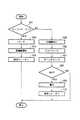
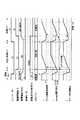
エンジンキースイッチ41がオンされると(ステップ101のYES)、車載バッテリ40からシステム制御器50へエンジンキースイッチ41を通して動作用電圧が供給され、システム制御器50が起動する。この起動時、システム制御器50内のタイムカウントtがクリアされ(ステップ102)、圧縮機21が起動され(ステップ103)、さらに保持リレー接点43がオンされる(ステップ104)。
【0072】
エンジンキースイッチ41がオフされると(ステップ101のNO)、システム制御器50に対するエンジンキースイッチ41経由の動作用電圧供給が解除となる。ただし、システム制御器50は、予め保持リレー接点43のオンして動作用電圧の受給およびそれに基づく動作を継続しており、エンジンキースイッチ41のオフに応答して圧縮機21を停止し(ステップ105)、冷凍サイクル中のバイパス回路に設けた圧力バランス弁を所定時間(30〜180秒程度)にわたりオンして冷媒圧力のバランスを取り冷凍サイクル中に発生した高圧冷媒と低圧冷媒の圧力差を小さくして(ステップ106)、さらにタイムカウントtを開始する(ステップ107)。このように、圧力バランスを取ることで、次回の圧縮機起動時における冷凍能力の立ち上がりをスムーズかつ迅速にすることができる。
【0073】
タイムカウントtが予め定められた設定時間t1(例えば5〜30分程度)に達しない間にエンジンキースイッチ41がオンされると(ステップ108のNO、ステップ101のYES)、タイムカウントtがクリアされ(ステップ102)、再び圧縮機21が起動するとともに(ステップ103)、圧力バランス弁がオフされる。
【0074】
タイムカウントtが設定時間t1に達すると(ステップ108のYES)、システム制御器50におけるそれまでの制御データ(運転履歴データ等)がシステム制御器50のメモリ(EEPROM)53に記憶され(ステップ109)、その記憶(書込み)の完了を待って保持リレー接点43がオフされる(ステップ110)。
【0075】
保持リレー接点43がオフすると、システム制御器50への動作用電圧供給が解除され、システム制御器50の動作が停止する。
【0076】
自己保持の設定時間t1は、冷凍車のそれまでの運転状況に応じて可変設定されるもので、システム制御器50の動作用電圧が頻繁に遮断されないような値が選択される。例えば、メモリ53に対する制御用データの書込回数の寿命が10万回、メモリ53の経年寿命が10年とすると、一日における動作用電圧の遮断可能な平均回数は、
[10万回/(10年×365日)]=27回/日に抑える必要がある。この遮断回数/日を満足し得る状態に自己保持の設定時間t1が決定される。なお、冷凍機20の運転率の面から見ると、遮断回数=0回が理想ではある。
【0077】
自己保持用の電源としては、車載バッテリ40に限らず、蓄電池ユニット30を使用しても、あるいは専用電源(蓄電池、コンデンサ等)を別途用意しても、そのいずれでもよい。
【0078】
保持リレー接点43のオンによる自己保持の開始タイミングについては、エンジンキースイッチ41のオフ時に限らず、発電機2の出力無しを検出したときでもよい。
【0079】
以上のように、システム制御器50に対する動作用電圧の供給をシステム制御器50が最適に自己管理することができる。
【0080】
したがって、頻繁に発停を繰り返す配送パターンで冷凍機20を運用する状況であっても、冷凍機20の再起動に際しては、冷凍サイクルの冷媒圧力のバランスが常に確保された状態にあり、しかも制御データの格納がそのデータ量の過少にかかわらず常に完了した状態にある。
【0081】
冷凍機20の再起動に際して冷凍サイクルの冷媒圧力のバランスが既に確保されていることにより、次回再起動時までの運転中断時間を解消することができ、しかも冷却能力の立ち上がりがスムーズかつ迅速になって冷却効率の向上が図れる。
【0082】
圧縮機21の再起動に際して制御データの格納が既に完了した状態にあることにより、運転履歴の解析などに際しての信頼性が大幅に向上する。
【0083】
動作用電圧の供給の自己保持については、設定時間t1という制限時間を設けているので、車載バッテリ40の過放電を防止することができる。しかも、設定時間t1については、メモリ53の書込回数寿命および経年寿命を考慮して決定しているので、メモリ53の劣化を極力防ぐことができる。
【0084】
(c)自動運転について説明する。
発電モードの運転中にエンジンキースイッチ41がオフされると(エンジン停止)、システム制御器50は、保持リレー接点43のオンによる自己保持動作を継続しながら、圧縮機21を一旦停止し、かつ自動電圧調整器8に停止指令を送信して発電機2の運転を停止し、自動電圧調整器8から停止完了信号を受信(発電停止)したら電磁開閉器3をオフする。そして、システム制御器50は、放電リレー接点6をオンし、蓄電池ユニット30を圧縮機21の駆動電源とした自動運転ヘ自動的に移行して、運転を再開する。
【0085】
この自動運転が開始された後、エンジンキースイッチ41がオンされず(エンジン停止、発電機停止)、しかも商用電源4が接続されないまま、第1の所定時間(例えば5分間)が経過すると、インバータ回路10の駆動が停止されるとともに放電リレー接点6がオフされ、自動運転が終了となる。その後、エンジンキースイッチ41がオンされず(エンジン停止、発電機停止)、しかも商用電源4が接続されないまま、さらに第2の所定時間が経過すると、システム制御器50はその直前にメモリ53にデータを保存した後、保持リレー接点43をオフして自己保持を終了する。
【0086】
第1の所定時間が経過する前の自動運転中、エンジンキースイッチ41がオンされたり(エンジン始動、発電機運転)、あるいは商用電源4が接続されると、自動運転が中断され、発電モードの運転あるいは商用モードの運転に復帰する。
【0087】
第1の所定時間が経過して自動運転が終了した後、第2の所定時間が経過する前に、エンジンキースイッチ41がオンされたり(エンジン始動、発電機運転)、あるいは商用電源4が接続されると、自己保持が終了することなく、発電モードの運転あるいは商用モードの運転に復帰する。
【0088】
ここまでの説明では、発電モード(あるいは商用モード)と自動運転の切換に際し、圧縮機21の駆動を一旦停止しているが、一旦停止による冷却効率の低下が無視できない、頻繁な走行・停止の繰り返しで平均冷却能力が確保できない、冷蔵庫(または冷凍庫)の扉開閉による品温上昇が無視できない、プルダウン性能を強化したい等の課題がある場合は、図4のフローチャートおよび図5のタイムチャートに示すように、圧縮機21の運転を継続しながらモードを切換える。
【0089】
図4および図5は、モード切換時、圧縮機21の運転を継続してインバータ回路10のV/F(電圧/周波数)パターンソフトの切換えを行った場合の動作を示している。尚、この動作では、庫内温度調節による圧縮機21の運転周波数Fが変化しないことを仮定した場合を示している。
【0090】
まず、放電リレー接点6を予めオンしておく(ステップ201)。発電モードで運転中、発電機2の出力が生じていれば、放電リレー接点6がオンしても、蓄電池ユニット30は放電しない。
【0091】
発電モードで運転中(ステップ202のYES)、エンジンキースイッチ41がオフ(エンジン停止)されたら(ステップ203のYES)、圧縮機21の運転周波数を所定値F1へ向け段階的に低下させる(ステップ204)。この場合、エンジン停止により発電機2の出力が生じないため、蓄電池ユニット30が放電し、その放電電力によって圧縮機21の運転が継続される。すなわち、発電モードから自動運転へと自動的に移行する。運転周波数Fの下降速度については、通常より速くしてもよい。例えば、運転周波数Fの下降速度を通常の1Hz/秒より速い60Hz/秒に設定する。
【0092】
運転周波数Fが所定値F1に到達したら(ステップ205のYES)、自動電圧調整器8に停止指令を送信して発電機2を停止し(ステップ206)、自動電圧調整器8から停止信号を受信(発電停止)したら電磁開閉器3をオフする(ステップ207)。
【0093】
システム制御器50が、使用する電源の種類に応じてインバータ回路10のV/Fパターンを選択的に設定する機能を有している場合は、第1の電磁開閉器3のオフタイミングの近傍(通常はオフした直後)でV/Fパターンを切換える(ステップ208)。このパターン切換時、電源電圧が発電モードのDC285Vから自動運転のDC240Vに下降することによりV/Fパターンを変えないと運転周波数Fが所定値F1より下降することになるため、インバータ回路10の出力電圧Vを設定値V1Aに向け段階的に上昇させ(ステップ209)、この間、インバータ回路10の出力周波数(運転周波数)Fは上記所定値F1に固定される(ステップ210)。出力電圧Vが設定値V1に到達したら(ステップ211のYES)、通常の運転周波数Fの制御へ移行する(ステップ212)。
【0094】
自動運転に移行後(ステップ202のNO)、エンジンキースイッチ41がオン(エンジン始動)されると(ステップ213のYES)、上記同様に、運転周波数Fを所定値F1まで段階的に低下させる(ステップ214)。この運転周波数Fの下降速度については、通常より速くしてもよい。
【0095】
運転周波数Fが所定値F1に到達したら(ステップ215のYES)、自動電圧調整器8に運転指令を送信して発電機2を運転し(ステップ216)、自動電圧調整器8から運転信号を受信(発電開始)したら電磁開閉器3をオンする(ステップ217)。すなわち、自動運転から発電モードへと自動的に移行する。
【0096】
そして、この電磁開閉器3のオンタイミングの近傍(通常はオンした直後)でV/Fパターンが切換えられる(ステップ208)。このとき、電源電圧が自動運転のDC240Vから発電モードのDC285Vに上昇することにより運転周波数Fが所定値F1より上昇することになるため、運転電圧Vをパターン設定値V1Bに向け段階的に下降させることにより(ステップ209)、この間、運転周波数Fは上記所定値F1に固定される(ステップ210)。出力電圧Vが設定値V1Bに到達したら(ステップ211のYES)、通常の運転周波数Fの制御へ移行する(ステップ212)。
【0097】
以上のように、エンジン1の運転・停止の切換に際し、圧縮機21の運転を継続しながら電源切換を最適に自動管理することができる。
【0098】
したがって、頻繁に発停が繰り返される配送パターンであっても、運転手や助手などの使用者は何もする必要がなく、よって使用者にかかる負担が軽減されるとともに、平均冷却能力およびプルダウン(急速冷却)性能の向上、冷蔵庫(または冷凍庫)の扉開閉時の品温上昇防止、圧縮機ブレークダウン防止(V/Fパターンソフト切換に基づく)、蓄電池節約(過放電の防止)などが可能となり、車両用冷凍装置としての高い信頼性を確保することができる。
【0099】
(d)アイドリングストップモードの運転について説明する。
エンジンキースイッチ41からシステム制御器50への動作用電圧の供給がなく、商用電源4の接続によるAC/DCコンバータ7からシステム制御器50への動作用電圧の供給も無い場合、アイドリングストップ運転スイッチ42が運転者により押圧操作(オン)されると、車載バッテリ40からアイドリングストップ運転スイッチ42経由でシステム制御器50に動作用電圧が供給されて、システム制御器50が起動する。アイドリングストップ運転スイッチ42は運転者が手を離すことですぐに復帰(オフ)するが、システム制御器50は動作用電圧の受給およびそれに伴う動作状態を保持リレー接点43のオンによって自己保持(バックアップ)する。
【0100】
同時に、システム制御器50は、アイドリングストップ運転スイッチ42の押圧操作に基づいてアイドリングストップモードを設定し、蓄電池ユニット30の放電による運転を開始する。すなわち、放電リレー接点6をオンして蓄電池ユニット30の放電電力をインバータ回路10に供給し、かつ運転周波数Fを制御する。
【0101】
こうして、自己保持(およびアイドリングストップモードの運転)が開始された後、エンジンキースイッチ41がオンされず(エンジン停止、発電機停止)、しかも商用電源4が接続されないまま、第3の所定時間が経過すると、インバータ回路10の駆動が停止されるとともに放電リレー接点6がオフされ、アイドリングストップモードの運転が終了となる。その後、エンジンキースイッチ41がオンされず(エンジン停止、発電機停止)、しかも商用電源4が接続されないまま、さらに第4の所定時間が経過すると、システム制御器50はその直前にメモリ53にデータを保存した後、保持リレー接点43をオフして自己保持を終了する。
【0102】
第3の所定時間が経過する前のアイドリングストップモードの運転中、エンジンキースイッチ41がオンされたり(エンジン始動、発電機運転)、あるいは商用電源4が接続されると、アイドリングストップモードの運転が中断され、発電モードの運転あるいは商用モードの運転が開始される。
【0103】
第3の所定時間が経過してアイドリングストップモードの運転が終了した後、第4の所定時間が経過する前に、エンジンキースイッチ41がオンされたり(エンジン始動、発電機運転)、あるいは商用電源4が接続されると、自己保持が終了することなく、発電モードの運転あるいは商用モードの運転が開始される。
【0104】
なお、アイドリングストップモードの運転は、実際には、コントローラ52の設定条件に応じて制御される。また、蓄電池ユニット30の過放電を防止することを目的に、アイドリングストップモードの運転の連続実行を禁止するなどの実行回数制限を設けてもよい。
【0105】
以上のように、コントローラ52とは独立してアイドリングストップモード専用の操作スイッチであるアイドリングストップ運転スイッチ42を設けていることにより、運転者の都合に応じた必要時に冷凍運転を即時に実行することができる。たとえば、庫内の予冷が必要になったとき、あるいは昼食休憩時など、適切な対応が可能である。
【0106】
(e)自動運転とアイドリングストップの運転の両立について説明する。
自動運転が実施されているとき、アイドリングストップ運転スイッチが押圧操作されると、アイドリングストップモードの手動運転が優先的に実施される。すなわち、アイドリングストップ運転スイッチが押圧操作された時点から第3の所定時間だけ、アイドリングストップモードの手動運転が行なわれる。その後、エンジンキースイッチ41がオンされず(エンジン停止、発電機停止)、しかも商用電源4が接続されないまま、第2の所定時間が経過すると、その直前にシステム制御器50においてメモリ53にデータが保存された後、自己保持が終了する。
【0107】
(f)アイドリングストップモード(自動運転およびアイドリングストップモードの運転)での蓄電池ユニット30の節約方法について、図6のタイムチャートを参照しながら説明する。
【0108】
冷凍機運転中、圧縮機21の運転周波数Fは、コントローラ52で設定された設定温度に基づいて決定される目標値と庫内温度センサ51で検知される庫内温度Trとの差より決定される。庫内温度Trが目標値(コントロール温度;設定温度に基づいて決定される)以下のときは、圧縮機21の運転を停止(サーモオフ)して、再び目標値を上回るまで停止状態を継続する。自動運転中およびアイドリングストップの運転中の庫内温度上昇をある程度許容できる場合、この目標値を、他電源(発電機2、商用電源4)で運転する場合と比較して高温側へシフト設定することにより、冷凍機20の運転率を低下させ、蓄電池ユニット30の消費を節約することができる。
【0109】
図6のタイムチャートは、発電モードと自動運転の切換を、圧縮機連続運転とした場合の、目標値に対するサーモオン,オフ(圧縮機21の運転/停止)の推移を示しており、発電モード時の目標値をT1、アイドリングストップモード時の目標値をT2とすると、例えばT1=(設定温度±0℃)、T2=(設定温度+5℃)が設定される。なお、サーモオン温度とサーモオフ温度との間には実際には所定の差が確保される。
【0110】
すなわち、発電モードの運転中、Tr≧T2の状態でエンジンキースイッチ41がオフ(エンジン停止)された場合は、サーモオンしたまま自動運転に切換わる。エンジンキースイッチ41がオン(エンジン再始動)されると、サーモオンしたまま発電モードに自動復帰する。
【0111】
発電モードの運転中、T1≦Tr<T2の状態でエンジンキースイッチ41がオフされた場合は、サーモオフして自動運転に切換わる。その後、Tr≧T2となればサーモオンする。
【0112】
T1≦Tr<T2の状態でサーモオフ中にエンジンキースイッチ41がオンされると、サーモオンして発電モードに自動復帰する。
【0113】
エンジンキースイッチ41のオフからオンまでの間、Tr<T2の状態が維持されれば、圧縮機21による蓄電池ユニット30の消費は零となる。
【0114】
したがって、体積・重量・コスト等の制約から容量の小さい蓄電池ユニット30が採用されている場合でも、蓄電池ユニット30の電力消費を節約して過放電を防止しながら、用途に応じた許容範囲内で庫内温度を最適にコントロールすることができる。
【0115】
なお、目標値T1,T2をコントローラ52上の操作(操作手段)で設定可能としてもよく、そうすることにより、被冷蔵品の種類、運用形態、用途等を考慮した最適な温度制御を使用者が自由に選択することが可能である。
【0116】
(g)システム制御器50による動作用電圧の受給およびそれに基づく動作状態の自己保持に関し、その自己保持の設定時間tの最適化手法について説明する。
自己保持の設定時間t1は、冷凍車の運用形態に応じて可変設定してもよい。例えば、宅配便のような頻繁に発停を繰り返す配送パターンの冷凍車の場合、自動運転後はt1=5分間(配送中等の短時間停車を想定)、アイドルストップモードの運転後はt1=30分間(昼食時等の長時間停車を想定)というように設定する。
なお、上記自動運転入切スイッチの操作によって自動運転を無効とした場合には、エンジン停止後はt1=10分間(冷凍/冷蔵荷物の積載なし)、商用電源4の遮断後はt1=2分間(短時間の停電を想定)とすればよい。
【0117】
こうすることにより、車載バッテリ40の過放電を防止しながら、冷凍車運用中のシステム制御器50に対する動作用電圧のオン,オフ回数を極力抑えることができる。
自己保持の設定時間t1をコントローラ52上の操作(操作手段)で可変設定できるようにしてもよい。
【0118】
(h)システム制御器50による動作用電圧の受給およびそれに基づく動作状態の自己保持を強制的に解除する方法について説明する。
動作用電圧の受給を即座に解除したい場合、また異常発生履歴を削除してシステムの再起動を図りたい場合は、動作用電圧の保持状態を手動操作で強制的に解除する手段を設けてもよい。例えば、解除スイッチを別途設ける、コントローラ52上の既存キーの複合操作などにより対応する。
このようにすれば、冷凍車運用中にシステムが異常停止した際にシステム再起動したい、点検・部品交換・修理等のサービスを行うために即座に電源を落としたい、などの要求に適切に対応することができる。
【0119】
(i)圧縮機21の運転周波数Fの変更速度について説明する。
庫内温度制御に基づく運転周波数制御に際し、運転周波数Fを所定速度で段階的に変化させているが、その変化の速度として、商用電源4などスタティックな特性の安定した電源を使用する場合は、冷凍サイクル系の安定を重視して1Hz/秒程度が選定されている。
これに対して、エンジン1の回転を動力源とした発電機2は、車両のアクセルワークに依存して、発電量および発電周波数がダイナミックに変動する特性を持つ。特に、製品のコストパフォーマンスを考慮した発電機仕様に起因して低回転域での発電電力不足が問題となる場合、およびエンジン1の低回転トルク不足が問題となる場合、一般的に、発電機回転数の領域別に運転周波数Fの上限値が設定される。また、走行中の平均冷却能力の観点から考えると、加速して発電電力量が十分となった場合には、速やかに冷凍能力を高めたいという要求がある。
【0120】
そこで、このような状況においては、走行中、すなわち発電機電源で運転中、運転周波数Fを目標値まで上昇/下降させるときのステップ変化速度を、他電源(商用電源4、蓄電池ユニット30)を使用した場合に比較して速くする。こうすることにより、車両の加減速に応答性よく追従する運転周波数制御を実行することができる。
運転周波数Fの下降速度を例えば通常の1Hz/秒から12Hz/秒に高めることにより、エンジン回転数が急激に落ち込んだ時、圧縮機21および発電機2のブレークダウン防止、車両のエンジンストール防止、蓄電池節約(発電機2のバックアップ電源として利用時)、などの効果が得られる。
運転周波数Fの上昇速度を例えば通常の1Hz/秒から2Hz/秒に高めることにより、車両が加速して発電機容量が十分となった場合、速やかに運転周波数Fをアップできることから、走行中の平均冷却能力向上、走行中のプルダウン性能向上などの効果が得られる。
これらの効果は、市街地等で頻繁に加減速を繰り返す走行パターンにおいて更に顕著となる。
【0121】
(j)充電専用モードについて説明する。
通常、蓄電池ユニット30の蓄電池33は、発電モード(エンジン運転中)または商用モード(商用電源4接続)で、冷凍機運転と並行して、充電回路32を介して充電される。しかし、発電モードの運転実施率よりもアイドリングストップモードの運転実施率が増した場合、あるいは暫く冷凍機運転を行わなかった場合など、単独で充電できると便利である。
そこで、蓄電池ユニット30に対する充電専用モードを設定するための操作手段を例えばコントローラ52に追加して設け、電磁開閉器3の閉成時(発電機運転時)または電磁開閉器5の閉成時(商用電源4接続時)、上記操作手段の操作によって充電専用モードが設定された場合に、スイッチング回路13を駆動しない構成を採用する。すなわち、冷凍機20を停止し、その状態で、発電機2の出力または商用電源4からの入力により蓄電池ユニット30を充電する。
【0122】
この充電専用モードについては、コントローラ52の既存操作の組合せで選択できるようにしてもよい。例えば、コントローラ52が操作電源キー(コントローラ操作の許可/禁止)、運転キー(冷凍機の運転/停止)を備えている場合には、走行中(エンジン運転中)は操作電源キーオンおよび運転キーオフ(停止)の操作があったとき、商用電源4の投入時は操作電源キーオフあるいは運転キーオフ(停止)の操作があったとき、それぞれ充電専用モードと定義して、冷凍機20を停止した状態で蓄電池ユニット30の充電を行う。
このような構成によれば、特別な充電専用ユニットを用意することなく、また、特別な操作部品を追加することなく、蓄電池ユニット30の単独充電が可能となる。
【0123】
[2]第2の実施形態について説明する。
図1において、二点鎖線で囲んで示す商用電源4、電磁開閉器5、AC/DCコンバータ7が除去される。
システム制御器50は、主要な機能として次の(11)〜(20)を有する。
【0124】
(11)エンジンキースイッチ41のオン,オフを検出し、自動電圧調整器8を介して発電機2の出力の有無を検出し、かつアイドリングストップ運転スイッチ42の押圧操作を検出する検出手段。
【0125】
(12)上記検出手段の検出結果(発電機2の出力の有無、アイドリングストップ運転スイッチ42の押圧操作)に応じて電磁開閉器3および放電リレー接点6を選択的に閉成するとともに、負荷に応じてスイッチング回路13の駆動および出力周波数を制御する制御手段。
具体的には、この制御手段は、エンジンキースイッチ41がオンで発電機2の出力が有る場合、電磁開閉器3を閉成して放電リレー接点6を開放する機能Aと、
エンジンキースイッチ41がオフで発電機2の出力が無い場合、アイドリングストップ運転スイッチ42の押圧操作に応じて、放電リレー接点6を閉成し電磁開閉器3を開放する機能Bと、を備えている。
なお、機能Aでは、電磁開閉器3を閉成して放電リレー接点6を開放するが、制御プログラムの設定変更により電磁開閉器3と放電リレー接点6を共に閉成してもよく、そうすることにより、発電機2からスイッチング回路13への電力供給と同時に蓄電池33を充電できるとともに、エンジン1の回転数が低くて発電機2の出力が低下した場合の供給電圧不足を蓄電池33の放電による補助的な電源供給によって補うことができる。
【0126】
(13)エンジンキースイッチ41のオン時にそのエンジンキースイッチ41を通して車載バッテリ40から電源供給を受けることにより動作し、その電源受給およびそれに基づく動作状態を、エンジンキースイッチ41のオフ後も、保持リレー接点43をオンして自己保持する第1の制御器電源保持手段。
【0127】
(14)上記エンジンキースイッチ41のオフによる車両用エンジン1の停止後、第1の所定時間にわたり、放電用リレー接点6をオンして蓄電池ユニット30の放電による自動運転を実行する制御手段。
【0128】
(15)上記エンジンキースイッチ41のオフによる車両用エンジン1の停止後、第1の所定時間が経過して(自動運転が終了)、さらに第2の所定時間が経過したとき、保持リレー接点43をオフして自己保持を終了し、車載バッテリ40から当該システム制御器50への電源供給を遮断する第1の電源遮断手段。
【0129】
(16)エンジンキースイッチ41からの電力の受給が無い場合、アイドリングストップ運転スイッチ42が押圧操作(オン)されると、そのアイドリングストップ運転スイッチ42を通して車載バッテリ40から電力を受けることにより動作し、その電力の受給およびそれに基づく動作状態を、アイドリングストップ運転スイッチ42の復帰(オフ)にかかわらず、保持リレー接点43のオンによって自己保持する第2の制御器電源保持手段。
【0130】
(17)上記アイドリングストップ運転スイッチ42が押圧操作後、第3の所定時間にわたり、放電用リレー接点6をオンして蓄電池ユニット30の放電によるアイドリングストップモードの運転を実行する制御手段。
【0131】
(18)上記第3の所定時間が経過して(アイドリングストップモードの運転が終了)、さらに第4の所定時間が経過したとき、保持リレー接点43をオフして自己保持を終了し、車載バッテリ40から当該システム制御器50への電源供給を遮断する第2の電源遮断手段。
【0132】
(19)上記自己保持を終了する直前に、それまでの制御データを内部の記憶素子たとえばメモリ(EEPROM)53に記憶する制御手段。
【0133】
(20)上記自己保持中に、前記冷凍サイクルにおける冷媒圧力をバランスさせるための圧力バランス制御を実行する制御手段。
【0134】
(21)コントローラ52の操作部における自動運転入切スイッチの操作に応じて自動運転の有効と無効を選択する手段。
【0135】
以上、商用電源4およびそれに関わる構成が取り除かれており、それ以外の構成および作用については第1の実施形態と同じである。よって、その詳細な説明は省略する。
なお、この発明は上記各実施形態に限定されるものではなく、要旨を変えない範囲で種々変形実施可能である。
【0136】
【発明の効果】
以上述べたようにこの発明によれば、制御データの確実な保存、制御データの記憶手段の寿命向上、次回再起動までの運転中断時間の軽減、次回再起動時の冷却能力の立ち上がりの迅速化およびそれに伴う冷却効率の向上などが図れる車両用冷凍装置を提供できる。
【図面の簡単な説明】
【図1】各実施形態の構成を示すブロック図。
【図2】各実施形態におけるシステム制御器の動作用電圧の自己保持を説明するためのフローチャート。
【図3】各実施形態におけるシステム制御器の動作用電圧の自己保持を説明するためのタイムチャート。
【図4】各実施形態における自動運転を説明するためのフローチャート。
【図5】各実施形態における自動運転を説明するためのタイムチャート。
【図6】各実施形態におけるサーモオン,オフの動作を説明するためのタイムチャート。
【符号の説明】
1…車両エンジン、2…発電機、3…電磁開閉器(第1開閉器)、4…商用電源(外部電源)、5…電磁開閉器(第2開閉器)、6…放電リレー接点(第3開閉器)、7…AC/DCコンバータ、8…自動電圧調整器、10…インバータ回路、11…整流回路、13…スイッチング回路、20…冷凍機、21…圧縮機、22…室外熱交換器、24…庫内熱交換器、30…蓄電池ユニット、33…蓄電池、40…車載バッテリ、41…エンジンキースイッチ(第1操作スイッチ)、42…アイドリングストップ運転スイッチ(第2操作スイッチ)、43…保持リレー接点、50…システム制御器、51…庫内温度センサ、52…コントローラ、53…メモリ(EEPROM)[0001]
BACKGROUND OF THE INVENTION
This invention is equipped with a refrigeration system powered by a generator driven by an engine and improves usability and cooling performance, especially in refrigerated vehicles that are operated in a delivery pattern that frequently starts and stops, such as courier services. The present invention relates to a vehicle refrigeration apparatus.
[0002]
[Prior art]
In a power generation type vehicle refrigeration system, for example, as shown in Japanese Patent Application No. 11-85993, a power source for inverter-driving an electric compressor is selected from a generator, a commercial power source, and a storage battery. There is something to do.
[0003]
Usually, the generator is used for a normal cooling operation while the engine is running, the commercial power source is used for a pre-cooling operation (standby operation) when a load is loaded, and the storage battery is used for a cold operation (idling stop operation) when the vehicle is stopped during delivery. The generator is the main power source for the operation of the refrigerator, and the commercial power source and storage battery have strong auxiliary elements.
[0004]
The controller switches these power sources and controls the entire refrigeration system. The power supply voltage is supplied from each of the above power sources or the vehicle-mounted battery by any of the engine key switch on, commercial power on, and idling stop operation switch on operations. The control operation is started. Further, the operation of the controller is stopped by cutting off the supply of the power supply voltage by any one of the engine key switch off, the commercial power supply cutoff, and the idling stop operation switch off.
[0005]
In addition, when a start operation of another mode operation is performed during operation in any one of the normal cooling operation, the pre-cooling operation, and the cold insulation operation, the controller determines the priority order and turns on the power of the refrigeration apparatus. However, since each power supply specification is different, the operation of the electric compressor is once stopped and then the mode operation is switched.
[0006]
A storage battery generally has a conservative setting of output specifications due to restrictions such as volume, weight, and cost. The generator is generally designed with an optimum output specification that takes into account the output and fluctuations in output accompanying the increase and decrease in engine speed. For example, the generator has three-phase 220V (this is rectified to become a
[0007]
[Problems to be solved by the invention]
The above-described vehicular refrigeration apparatus has the following problems particularly in a situation where the vehicle is operated in a delivery pattern that frequently starts and stops, such as a home delivery service.
[0008]
(1) A manual operation is required to perform the idling stop operation when the engine is stopped at the time of delivery, and the manual operation is required every time the engine is stopped. It becomes. In addition, there is a concern about an increase in the internal temperature due to forgetting to operate, and consequently an increase in the internal temperature of the storage.
[0009]
(2) When storing the control data up to that time in the storage element (EEPROM, etc.) when the controller power is shut down, if the power shuts off frequently, the number of data writing increases and the life of the storage element is shortened. . In addition, since there is no time to power off, it is difficult to completely store the data when there is a large amount of data to be stored.
[0010]
(3) As a means to compensate for the problem of (2) above, it is conceivable to constantly supply the operating voltage from the vehicle battery or the like to the controller. Etc. are concerned. Even if the operation voltage supply is turned on and off by a manual switch, the same problem occurs due to forgetting to turn off the manual switch.
[0011]
(4) Since the compressor is temporarily stopped when the power is shut off or switched, a long time is required to balance the refrigerant pressure in the refrigeration cycle, and a long delay time must be ensured until the next restart. However, it takes time until a predetermined cooling capacity is obtained even after restarting.
[0012]
The present invention takes the above-mentioned circumstances into consideration, and the object of the present invention is to make it possible to always perform an appropriate operation without being affected by the operating condition of the engine and without burdening the user. An object of the present invention is to provide a vehicular refrigeration apparatus having excellent reliability capable of eliminating problems such as a rise.
[0013]
In addition, the present invention can reliably save control data, improve the life of the storage means for control data, eliminate the operation interruption time until the next restart, speed up the rise of the cooling capacity at the next restart, and the accompanying cooling efficiency It is an object of the present invention to provide a vehicular refrigeration apparatus that can improve the efficiency of the vehicle.
[0014]
[Means for Solving the Problems]
A refrigeration apparatus for a vehicle according to a first aspect of the invention includes a generator driven by a vehicle engine, a storage battery unit charged by the output of the generator, and a switching circuit that converts the output of the generator or the storage battery into alternating current. The compressor driven by the output of the switching circuit, the refrigerator having a refrigeration cycle in which refrigerant is circulated by the compressor, and the power source of the compressor are switched to either a generator or a storage battery unit. A controller and a controller power source that supplies power to the controller from a power storage type power source, and performs freezing or refrigeration by driving a compressor by any one of the power source of the generator, commercial power source or storage battery unit Even after the vehicle engine is stopped or the operation by the storage battery unit is stopped, power from the controller power source to the controller is A controller power supply holding means for continuing supply; and after the vehicle engine is stopped or the operation by the storage battery unit is stopped, the controller power supply holding means is controlled after a predetermined time so that the controller power supply is supplied to the controller. Power supply cutoff means for cutting off power supply.
[0015]
According to a second aspect of the present invention, there is provided a vehicular refrigeration apparatus including a generator driven by a vehicular engine, an input terminal of a commercial power source, a storage battery unit charged by the generator or a commercial power input, a generator, and a commercial power source. Alternatively, a switching circuit for converting the output of the storage battery into alternating current, a compressor driven by the output of the switching circuit, a refrigerator having a refrigeration cycle in which refrigerant is circulated by the compressor, and supply of power to the compressor A controller that switches between a generator, a commercial power source, and a storage battery unit; and a controller power source that supplies power to the controller from either a commercial power source or a storage-type power source. The compressor is driven by either a power source or a storage battery unit to perform freezing or refrigeration, and the vehicle engine is stopped. Controller power supply holding means for continuing power supply from the controller power supply to the controller even after the operation by the commercial power supply or the storage battery unit is stopped, stop of the vehicle engine, the commercial power supply or the storage battery unit And a power cutoff means for controlling the controller power supply holding means after a predetermined time after the operation is stopped to cut off the power supply from the controller power supply to the controller.
[0016]
The vehicular refrigeration apparatus of the invention according to claim 3 is limited to the controller in the invention according to claim 1 or claim 2. The controller includes storage means for storing and holding the control data without supplying power, and also has storage control means for storing the control data so far in the storage means immediately before the end of self-holding.
[0017]
The refrigeration apparatus for a vehicle according to a fourth aspect of the invention limits the controller in the invention according to any one of the first to third aspects. The controller further includes control means for executing pressure balance control for balancing refrigerant pressure in the refrigeration cycle during self-holding.
[0018]
A refrigeration apparatus for a vehicle according to a fifth aspect of the invention is charged by a generator driven by a vehicle engine, a rectifier circuit that rectifies an output of the generator or an input from a commercial power source, and an output of the rectifier circuit. A storage battery unit, a switching circuit for converting the output of the rectifier circuit or the discharge output of the storage battery unit into an alternating current, a compressor driven by the output of the switching circuit, and a current path from the generator to the rectifier circuit A first switch provided in the power supply, a second switch provided in the current path from the commercial power source to the rectifier circuit, and a third switch provided in the discharge path from the storage battery unit to the switching circuit. And an operation switch for switching between operation and stop of the engine, and detection means for detecting the presence or absence of the output of the generator and the presence or absence of input from the commercial power source Control means for selectively closing the first switch, the second switch, and the third switch according to the detection result of the detection means, and controlling the drive and output frequency of the switching circuit according to the load And when the operation switch is turned on, it operates by receiving power from the controller power source through the operation switch, and receives power supply from the controller power source for a predetermined time after the operation switch is turned off and self-holds the operation state. And a controller having control means.
[0019]
A refrigeration apparatus for a vehicle according to a sixth aspect of the invention is charged by a generator driven by a vehicle engine, a rectifier circuit that rectifies an output of the generator or an input from a commercial power source, and an output of the rectifier circuit. A storage battery unit, a switching circuit for converting the output of the rectifier circuit or the discharge output of the storage battery unit into an alternating current, a compressor driven by the output of the switching circuit, and a current path from the generator to the rectifier circuit A first switch provided in the power supply, a second switch provided in the current path from the commercial power source to the rectifier circuit, and a third switch provided in the discharge path from the storage battery unit to the switching circuit. And a first operation switch for switching between operation and stop of the engine, and a setting for switching between operation and stop of the vehicle refrigeration apparatus when the engine is stopped. A second operation switch for detecting the presence / absence of the output of the generator and the presence / absence of input from the commercial power source, and the detection result of the detection unit and the operation state of the second operation switch. The first switch, the second switch, and the third switch are selectively closed, and have control means for controlling the drive and output frequency of the switching circuit according to a load, and the first operation switch Or a control means that operates by receiving power from the controller power supply through the operation switch when the second operation switch is turned on, and that self-holds the power reception and the operation state based on the power supply for a predetermined time after the operation switch is turned off. Having a controller.
[0020]
The vehicular refrigeration apparatus of the invention according to claim 7 is limited to the controller in the invention according to
[0021]
The vehicular refrigeration apparatus according to an eighth aspect of the present invention limits the controller in any one of the fifth to seventh aspects of the present invention. The controller further includes storage means for storing and holding the control data without supplying power, and has control means for storing the control data so far in the storage means immediately before the end of self-holding.
[0022]
A vehicle refrigeration apparatus according to a ninth aspect of the present invention is the refrigeration apparatus for a vehicle according to any of the fifth to seventh aspects, further comprising a refrigeration cycle in which the refrigerant discharged from the compressor circulates. The controller further includes control means for performing pressure balance control for balancing refrigerant pressure in the refrigeration cycle during self-holding.
[0023]
According to a tenth aspect of the present invention, there is provided a vehicular refrigeration apparatus according to any one of the first, second, fifth, and sixth aspects, wherein the controller power supply is an in-vehicle battery. Yes.
[0024]
The refrigeration apparatus for a vehicle according to an eleventh aspect of the invention is limited to any one of the first, second, fifth, and sixth aspects, wherein the controller power supply is also used as a storage battery unit. is doing.
[0025]
The vehicular refrigeration apparatus according to the twelfth aspect of the present invention is limited to the controller power supply in the second or sixth aspect of the invention. The power supply for the controller is supplied from an in-vehicle battery or a storage battery unit, and is supplied from the commercial power supply when the commercial power supply is input.
[0026]
A refrigeration apparatus for a vehicle according to a thirteenth aspect of the invention is charged by a generator driven by a vehicle engine, a rectifier circuit that rectifies the output of the generator or an input from a commercial power source, and the output of the rectifier circuit. A storage battery unit, a switching circuit for converting the output of the rectifier circuit or the discharge output of the storage battery unit into an alternating current, a compressor driven by the output of the switching circuit, and a current path from the generator to the rectifier circuit A first switch provided in the power supply, a second switch provided in the current path from the commercial power source to the rectifier circuit, and a third switch provided in the discharge path from the storage battery unit to the switching circuit. And an operation switch for switching between operation and stop of the engine, and detection means for detecting the presence or absence of the output of the generator and the presence or absence of input from the commercial power source The first switch, the second switch, and the third switch are selectively closed according to the detection result of the detection means, and the drive and output frequency of the switching circuit are controlled according to the load. And a control means for continuing to drive the switching circuit at the time of closing switching of each switch.
[0027]
A refrigeration apparatus for a vehicle according to a fourteenth aspect of the invention is charged by a generator driven by a vehicle engine, a rectifier circuit that rectifies an output of the generator or an input from a commercial power source, and an output of the rectifier circuit. A storage battery unit, a switching circuit for converting the output of the rectifier circuit or the discharge output of the storage battery unit into an alternating current, a compressor driven by the output of the switching circuit, and a current path from the generator to the rectifier circuit A first switch provided in the power supply, a second switch provided in the current path from the commercial power source to the rectifier circuit, and a third switch provided in the discharge path from the storage battery unit to the switching circuit. And a first operation switch for switching between operation and stop of the engine, and a setting for switching between operation and stop of the vehicle refrigeration apparatus when the engine is stopped. A second operation switch for detecting the presence or absence of the output of the generator and the presence or absence of input from the commercial power supply, and the first switch and the second switch according to the detection result of the detection means A control means for selectively closing the third switch, controlling the driving and output frequency of the switching circuit according to the load, and continuing the driving of the switching circuit at the time of switching switching of each switch; I have.
[0028]
The refrigeration apparatus for a vehicle according to a fifteenth aspect of the present invention limits the control means in the thirteenth or fourteenth aspect of the present invention. The control means continues the driving of the switching circuit at the time of closing switching of each switch and reduces the output frequency of the switching circuit to a predetermined value.
[0029]
According to a sixteenth aspect of the present invention, in the refrigeration apparatus for a vehicle according to any one of the thirteenth to fifteenth aspects, the control means is limited. After the engine stops, the control means continues to drive the switching circuit when the power supply source to the compressor is switched from the generator to the storage battery unit, and the output frequency of the switching circuit is reduced to a predetermined value at a faster speed than during normal operation. Let
[0030]
The vehicular refrigeration apparatus of the invention according to claim 17 limits the control means in any of the inventions of claims 13 to 16. The control means switches the output voltage / output frequency pattern of the switching circuit in accordance with the selective closing of each switch, and at the time of the switching, gradually reduces the output voltage of the switching circuit to a predetermined value and reduces the output frequency. Fixed to a predetermined value.
[0031]
A refrigeration apparatus for a vehicle according to an eighteenth aspect of the invention is charged by a generator driven by a vehicle engine, a rectifier circuit that rectifies the output of the generator or an input from a commercial power source, and the output of the rectifier circuit. A storage battery unit, a switching circuit for converting the output of the rectifier circuit or the discharge output of the storage battery unit into an alternating current, a compressor driven by the output of the switching circuit, and a current path from the generator to the rectifier circuit A first switch provided in the power supply, a second switch provided in the current path from the commercial power source to the rectifier circuit, and a third switch provided in the discharge path from the storage battery unit to the switching circuit. And an operation switch for switching between operation and stop of the engine, and detection means for detecting the presence or absence of the output of the generator and the presence or absence of input from the commercial power source Control for selectively closing the first switch, the second switch, and the third switch according to the detection result of the detection means, and controlling the drive and output frequency of the switching circuit according to the load Means. This control means increases the change speed of the output frequency of the switching circuit at the time of power supply by the generator than at the time of power supply by the commercial power supply or the storage battery unit.
[0032]
According to a nineteenth aspect of the present invention, a vehicular refrigeration apparatus is charged by a generator driven by a vehicular engine, a rectifier circuit that rectifies an output of the generator or an input from a commercial power source, and an output of the rectifier circuit. A storage battery unit, a switching circuit for converting the output of the rectifier circuit or the discharge output of the storage battery unit into an alternating current, a compressor driven by the output of the switching circuit, and a current path from the generator to the rectifier circuit A first switch provided in the power supply, a second switch provided in the current path from the commercial power source to the rectifier circuit, and a third switch provided in the discharge path from the storage battery unit to the switching circuit. And a first operation switch for switching between operation and stop of the engine and a setting for switching between operation and stop of the vehicle refrigeration apparatus when the engine is stopped. A second operation switch for detecting the presence or absence of the output of the generator and the presence or absence of input from the commercial power source, the detection result of the detection means and the operation state of the second operation switch Control means for selectively closing the first switch, the second switch, and the third switch and controlling the driving and output frequency of the switching circuit according to the load. This control means increases the change speed of the output frequency of the switching circuit at the time of power supply by the generator than at the time of power supply by the commercial power supply or the storage battery unit.
[0033]
A refrigeration apparatus for a vehicle according to a twentieth aspect of the invention is charged by a generator driven by a vehicle engine, a rectifier circuit that rectifies an output of the generator or an input from a commercial power source, and an output of the rectifier circuit. A storage battery unit, a switching circuit for converting the output of the rectifier circuit or the discharge output of the storage battery unit into an alternating current, a compressor driven by the output of the switching circuit, and a current path from the generator to the rectifier circuit A first switch provided in the power supply, a second switch provided in the current path from the commercial power source to the rectifier circuit, and a third switch provided in the discharge path from the storage battery unit to the switching circuit. And an operation switch for switching between operation and stop of the engine, and detection means for detecting the presence or absence of the output of the generator and the presence or absence of input from the commercial power source Control for selectively closing the first switch, the second switch, and the third switch according to the detection result of the detection means, and controlling the drive and output frequency of the switching circuit according to the load And an operation means for setting a charge-only mode for the storage battery unit. The control means does not drive the switching circuit when the charge only mode is set when the first switch or the second switch is closed.
[0034]
A refrigeration apparatus for a vehicle according to a twenty-first aspect of the invention is charged by a generator driven by a vehicle engine, a rectifier circuit that rectifies an output of the generator or an input from a commercial power source, and an output of the rectifier circuit. A storage battery unit, a switching circuit for converting the output of the rectifier circuit or the discharge output of the storage battery unit into an alternating current, a compressor driven by the output of the switching circuit, and a current path from the generator to the rectifier circuit A first switch provided in the power supply, a second switch provided in the current path from the commercial power source to the rectifier circuit, and a third switch provided in the discharge path from the storage battery unit to the switching circuit. And a first operation switch for switching between operation and stop of the engine and a setting for switching between operation and stop of the vehicle refrigeration apparatus when the engine is stopped. A second operation switch for detecting the presence or absence of the output of the generator and the presence or absence of input from the commercial power source, and the detection result of the detection unit and the operation state of the second operation switch Control means for selectively closing the first switch, the second switch, and the third switch and controlling the drive and output frequency of the switching circuit in accordance with the load. Furthermore, an operation means for setting a charge-only mode for the storage battery unit is provided. The control means does not drive the switching circuit when the charge only mode is set when the first switch or the second switch is closed.
[0035]
DETAILED DESCRIPTION OF THE INVENTION
[1] A first embodiment of the present invention will be described below with reference to the drawings.
As shown in FIG. 1, a generator 2 is connected to a vehicle engine 1 which is a power source of a refrigeration vehicle via a belt or the like. The generator 2 is mechanically driven by the power of the vehicular engine 1 and generates AC power (for example, three-phase 220V voltage). An
[0036]
The commercial power supply 4 (so-called city power supply facility), which is an external power supply, can be used at a predetermined location. A connection terminal X that can be freely connected to and disconnected from the
[0037]
The
[0038]
The
[0039]
The switching circuit 13 converts the output of the
[0040]
The
[0041]
On the other hand, an AC / DC converter 7 that converts the AC voltage of the
[0042]
An automatic voltage regulator (AVR) 8 is connected to the generator 2. The
[0043]
An engine key switch switch (first operation switch) 41, an idling stop operation switch (second operation switch) 42, and a holding relay contact (normally open contact) 43 are respectively mounted on an in-vehicle battery (power storage type power supply) 40 of the refrigerator car. A
[0044]
An internal temperature sensor 51 and a
[0045]
As the operation mode of the present embodiment, the generator mode operation based on the output of the generator 2 based on the engine operation, the commercial mode operation based on the connection of the
[0046]
The
[0047]
(1) The on / off of the engine
[0048]
(2) The
More specifically, this control means closes the electromagnetic switch 3 to open the
When the engine
A function C for closing the
When the engine
In function A, the electromagnetic switch 3 is closed and the
[0049]
(3) When the engine
[0050]
(4) After the engine
[0051]
(5) After the vehicle engine 1 is stopped by turning off the engine
[0052]
(6) When neither the reception of power from the engine
[0053]
(7) Control means for performing the operation in the idling stop mode by discharging the
[0054]
(8) When the third predetermined time elapses (the operation in the idling stop mode ends) and when the fourth predetermined time elapses, the holding
[0055]
(9) Control means for storing control data so far in an internal storage element, for example, a memory (EEPROM) 53, immediately before the end of the self-holding.
[0056]
(10) Control means for executing pressure balance control for balancing refrigerant pressure in the refrigeration cycle during the self-holding.
[0057]
(11) Means for selecting whether automatic driving is enabled or disabled in accordance with the operation of the automatic driving on / off switch in the operation unit of the
[0058]
Next, the operation of the above configuration will be described.
(A) First, the basic operation will be described.
When the engine
[0059]
When an operation for starting operation (operation switch on) is performed by the
[0060]
When the electromagnetic switch 3 is turned on, the output of the generator 2 is supplied to the
[0061]
The internal temperature sensor 51 detects the internal temperature Tr, the detected temperature Tr is compared with a target value based on the set temperature set by the
[0062]
On the other hand, when the engine
[0063]
When the
[0064]
In addition, when the engine
[0065]
When the discharge relay contact 6 is closed, the
[0066]
In short, only the electromagnetic switch 3 is closed when the output of the generator 2 is present, and only the
[0067]
When the predetermined time has elapsed, the
[0068]
Further, when the detected temperature Tr exceeds the target value, the switching circuit 13 is driven so that the output frequency F of the switching circuit 13 corresponds to the difference between the detected temperature Tr and the target value, and the detected temperature Tr is less than the target value. Sometimes the switching circuit 13 is stopped.
[0069]
That is, the
[0070]
(B) Next, the self-holding of the operating voltage of the
[0071]
When the engine
[0072]
When the engine
[0073]
If the engine
[0074]
When the time count t reaches the set time t1 (YES in Step 108), the control data (operation history data etc.) in the
[0075]
When the holding
[0076]
The self-holding set time t1 is variably set according to the operation state of the refrigerator until then, and a value is selected so that the operating voltage of the
[100,000 times / (10 years × 365 days)] = 27 times / day. The set time t1 for self-holding is determined so as to satisfy the number of shut-off times / day. From the viewpoint of the operating rate of the
[0077]
The power source for self-holding is not limited to the in-
[0078]
The start timing of self-holding when the holding
[0079]
As described above, the
[0080]
Therefore, even when the
[0081]
Since the refrigerant pressure balance of the refrigeration cycle is already secured when the
[0082]
Since the storage of the control data has already been completed when the
[0083]
As for the self-holding of the supply of the operating voltage, since the time limit of the set time t1 is provided, the over-discharge of the in-
[0084]
(C) Automatic operation will be described.
When the engine
[0085]
After the automatic operation is started, if the engine
[0086]
If the engine
[0087]
After the first predetermined time elapses and the automatic operation ends, before the second predetermined time elapses, the engine
[0088]
In the description so far, when switching between the power generation mode (or commercial mode) and automatic operation, the drive of the
[0089]
4 and 5 show the operation when the operation of the
[0090]
First, the discharge relay contact 6 is turned on in advance (step 201). If the output of the generator 2 is generated during operation in the power generation mode, the
[0091]
If the engine
[0092]
When the operating frequency F reaches the predetermined value F1 (YES in step 205), a stop command is transmitted to the
[0093]
When the
[0094]
After shifting to automatic operation (NO in step 202), when the engine
[0095]
When the operating frequency F reaches the predetermined value F1 (YES in step 215), an operation command is transmitted to the
[0096]
The V / F pattern is switched in the vicinity of the on-timing of the electromagnetic switch 3 (usually immediately after it is turned on) (step 208). At this time, since the operating frequency F rises from the predetermined value F1 when the power supply voltage rises from
[0097]
As described above, when switching between operation and stop of the engine 1, it is possible to optimally automatically manage power switching while continuing the operation of the
[0098]
Therefore, even if the delivery pattern is frequently started and stopped, there is no need for the driver or assistant user to do anything, so the burden on the user is reduced, and the average cooling capacity and pull-down ( Rapid cooling) performance improvement, prevention of temperature rise when opening / closing the refrigerator (or freezer) door, prevention of compressor breakdown (based on V / F pattern software switching), saving of storage battery (prevention of overdischarge), etc. High reliability as a vehicular refrigeration apparatus can be ensured.
[0099]
(D) The operation in the idling stop mode will be described.
When no operation voltage is supplied from the engine
[0100]
At the same time, the
[0101]
Thus, after self-holding (and idling stop mode operation) is started, the engine
[0102]
If the engine
[0103]
After the third predetermined time has elapsed and the idling stop mode operation has ended, before the fourth predetermined time has elapsed, the engine
[0104]
The operation in the idling stop mode is actually controlled according to the setting conditions of the
[0105]
As described above, the idling
[0106]
(E) The coexistence of automatic operation and idling stop operation will be described.
If the idling stop operation switch is pressed while automatic operation is being performed, manual operation in the idling stop mode is preferentially performed. That is, manual operation in the idling stop mode is performed for a third predetermined time from the time when the idling stop operation switch is pressed. Thereafter, when the engine
[0107]
(F) A method for saving the
[0108]
During the operation of the refrigerator, the operating frequency F of the
[0109]
The time chart of FIG. 6 shows the transition of thermo on / off (operation / stop of the compressor 21) with respect to the target value when switching between the power generation mode and the automatic operation is the compressor continuous operation. For example, T1 = (set temperature ± 0 ° C.) and T2 = (set temperature + 5 ° C.) are set, where T1 is the target value and T2 is the target value in the idling stop mode. Note that a predetermined difference is actually ensured between the thermo-on temperature and the thermo-off temperature.
[0110]
That is, during operation in the power generation mode, when the engine
[0111]
When the engine
[0112]
When the engine
[0113]
If the state of Tr <T2 is maintained from the time when the engine
[0114]
Therefore, even when the
[0115]
It should be noted that the target values T1 and T2 may be set by an operation (operation means) on the
[0116]
(G) Regarding the reception of the operating voltage by the
The set time t1 for self-holding may be variably set according to the operation mode of the refrigerator car. For example, in the case of a freezing vehicle with a delivery pattern that frequently starts and stops, such as a courier service, t1 = 5 minutes after automatic operation (assuming a short stop such as during delivery), and t1 = 30 after operation in idle stop mode. Set for minutes (assuming long stoppages such as lunch).
When the automatic operation is disabled by operating the automatic operation on / off switch, t1 = 10 minutes (no refrigerated / refrigerated baggage is loaded) after the engine is stopped, and t1 = 2 minutes after the
[0117]
By doing so, it is possible to minimize the number of times the operating voltage is turned on and off with respect to the
The setting time t1 for self-holding may be variably set by an operation (operation means) on the
[0118]
(H) A method for forcibly releasing the operation voltage received by the
If you want to cancel the receipt of the operating voltage immediately, or if you want to restart the system by deleting the error occurrence history, you can provide a means to forcibly release the operating voltage holding state by manual operation. Good. For example, a release switch is provided separately, and this is handled by a composite operation of existing keys on the
In this way, we can respond appropriately to requests such as wanting to restart the system when the system stops abnormally during refrigerated vehicle operation, or immediately turning off the power for service such as inspection, parts replacement, and repair. can do.
[0119]
(I) The changing speed of the operating frequency F of the
In the operation frequency control based on the internal temperature control, the operation frequency F is changed stepwise at a predetermined speed. As the speed of the change, when using a power source with stable static characteristics such as the
On the other hand, the generator 2 using the rotation of the engine 1 as a power source has a characteristic that the power generation amount and the power generation frequency dynamically change depending on the accelerator work of the vehicle. In particular, when the shortage of generated power in the low rotation range is a problem due to the generator specifications considering the cost performance of the product, and when the shortage of the low rotation torque of the engine 1 is a problem, the generator is generally An upper limit value of the operating frequency F is set for each rotation speed region. Further, from the viewpoint of the average cooling capacity during traveling, there is a demand for promptly increasing the refrigerating capacity when the amount of generated power becomes sufficient after acceleration.
[0120]
Therefore, in such a situation, while driving, that is, during operation with the generator power source, the step change rate when the operating frequency F is increased / decreased to the target value is changed to the other power source (
By increasing the descending speed of the operating frequency F from, for example, the usual 1 Hz / second to 12 Hz / second, when the engine speed drops sharply, the
For example, when the vehicle is accelerated and the generator capacity becomes sufficient by increasing the rising speed of the driving frequency F from, for example, 1 Hz / second to 2 Hz / second, the driving frequency F can be quickly increased. Effects such as improved average cooling capacity and improved pull-down performance during driving can be obtained.
These effects become more prominent in a traveling pattern in which acceleration / deceleration is frequently repeated in an urban area or the like.
[0121]
(J) The charge-only mode will be described.
Usually, the
Therefore, an operation means for setting the charge-only mode for the
[0122]
The charge-only mode may be selected by a combination of existing operations of the
According to such a configuration, it is possible to charge the
[0123]
[2] A second embodiment will be described.
In FIG. 1, the
The
[0124]
(11) Detection means for detecting on / off of the engine
[0125]
(12) The electromagnetic switch 3 and the discharge relay contact 6 are selectively closed according to the detection result of the detection means (the presence or absence of the output of the generator 2, the pressing operation of the idling stop operation switch 42), and the load Control means for controlling the drive and output frequency of the switching circuit 13 accordingly.
Specifically, this control means includes a function A for closing the electromagnetic switch 3 and opening the discharge relay contact 6 when the engine
A function B that closes the discharge relay contact 6 and opens the electromagnetic switch 3 in response to a pressing operation of the idling
In the function A, the electromagnetic switch 3 is closed and the discharge relay contact 6 is opened, but both the electromagnetic switch 3 and the discharge relay contact 6 may be closed by changing the setting of the control program. As a result, the
[0126]
(13) When the engine
[0127]
(14) Control means for executing automatic operation by discharging the
[0128]
(15) After the vehicle engine 1 is stopped by turning off the engine
[0129]
(16) When no power is received from the engine
[0130]
(17) Control means for performing the operation in the idling stop mode by discharging the
[0131]
(18) When the third predetermined time elapses (the operation in the idling stop mode ends) and when the fourth predetermined time elapses, the holding
[0132]
(19) Control means for storing control data so far in an internal storage element, for example, a memory (EEPROM) 53, immediately before the end of self-holding.
[0133]
(20) Control means for performing pressure balance control for balancing refrigerant pressure in the refrigeration cycle during the self-holding.
[0134]
(21) Means for selecting whether automatic driving is enabled or disabled according to the operation of the automatic driving on / off switch in the operation unit of the
[0135]
As described above, the
In addition, this invention is not limited to said each embodiment, A various deformation | transformation implementation is possible in the range which does not change a summary.
[0136]
【The invention's effect】
As described above, according to the present invention, reliable storage of control data, improvement in the life of the storage means for control data, reduction of operation interruption time until the next restart, rapid startup of cooling capacity at the next restart And the refrigeration apparatus for vehicles which can aim at the improvement of the cooling efficiency accompanying it, etc. can be provided.
[Brief description of the drawings]
FIG. 1 is a block diagram showing a configuration of each embodiment.
FIG. 2 is a flowchart for explaining self-holding of an operation voltage of a system controller in each embodiment.
FIG. 3 is a time chart for explaining self-holding of an operation voltage of a system controller in each embodiment.
FIG. 4 is a flowchart for explaining automatic driving in each embodiment.
FIG. 5 is a time chart for explaining automatic driving in each embodiment.
FIG. 6 is a time chart for explaining a thermo-on / off operation in each embodiment.
[Explanation of symbols]
DESCRIPTION OF SYMBOLS 1 ... Vehicle engine, 2 ... Generator, 3 ... Electromagnetic switch (1st switch), 4 ... Commercial power supply (external power supply), 5 ... Electromagnetic switch (2nd switch), 6 ... Discharge relay contact (1st 3 switch), 7 ... AC / DC converter, 8 ... automatic voltage regulator, 10 ... inverter circuit, 11 ... rectifier circuit, 13 ... switching circuit, 20 ... refrigerator, 21 ... compressor, 22 ... outdoor heat exchanger , 24 ... heat exchanger in the cabinet, 30 ... storage battery unit, 33 ... storage battery, 40 ... vehicle battery, 41 ... engine key switch (first operation switch), 42 ... idling stop operation switch (second operation switch), 43 ... Holding relay contact, 50 ... system controller, 51 ... internal temperature sensor, 52 ... controller, 53 ... memory (EEPROM)
Claims (21)
Translated fromJapanese前記車両用エンジンの停止または前記蓄電池ユニットによる運転の停止後も前記制御器用電源から前記制御器への電源供給を継続する制御器電源保持手段と、
前記車両用エンジンの停止または前記蓄電池ユニットによる運転の停止後、所定時間後に前記制御器電源保持手段を制御して前記制御器用電源から前記制御器への電源供給を遮断する電源遮断手段と、
を備えたことを特徴とする車両用冷凍装置。A generator driven by a vehicle engine, a storage battery unit charged by the output of the generator, a switching circuit for converting the output of the generator or the storage battery into alternating current, and a compressor driven by the output of the switching circuit A compressor having a refrigeration cycle in which refrigerant is circulated by the compressor, a controller that switches a power supply source of the compressor to either a generator or a storage battery unit, and a storage-type power source to the controller A vehicular refrigeration apparatus that performs refrigeration or refrigeration by driving a compressor with the power source of any one of the generator, the commercial power source, or the storage battery unit.
Controller power supply holding means for continuing power supply from the controller power supply to the controller even after the vehicle engine is stopped or the storage battery unit is stopped.
A power shut-off means for controlling the controller power supply holding means after a predetermined time after the vehicle engine is stopped or the operation of the storage battery unit is stopped to shut off the power supply from the controller power supply to the controller;
A vehicular refrigeration apparatus comprising:
前記車両用エンジンの停止、前記商用電源または前記蓄電池ユニットによる運転の停止後も前記制御器用電源から前記制御器への電源供給を継続する制御器電源保持手段と、
前記車両用エンジンの停止、前記商用電源または前記蓄電池ユニットによる運転の停止後、所定時間後に前記制御器電源保持手段を制御して前記制御器用電源から前記制御器への電源供給を遮断する電源遮断手段と、
を備えたことを特徴とする車両用冷凍装置。A generator driven by a vehicle engine, an input terminal of a commercial power source, a storage battery unit charged by the generator or the commercial power source input, a switching circuit that converts the output of the generator, the commercial power source or the storage battery into an alternating current; The compressor driven by the output of the switching circuit, the refrigerator having a refrigeration cycle in which the refrigerant is circulated by the compressor, and the power source of the compressor is any of a generator, a commercial power source, or a storage battery unit And a controller power source that supplies power to the controller from either a commercial power source or a storage-type power source, and the compressor is operated by any one of the power source of the generator, the commercial power source, or the storage battery unit. In a vehicle refrigeration apparatus that drives and freezes or refrigerates,
Controller power supply holding means for continuing power supply from the controller power supply to the controller even after the vehicle engine is stopped, the commercial power supply or the storage battery unit is stopped.
After the vehicle engine is stopped, the commercial power supply or the operation of the storage battery unit is stopped, the controller power supply holding means is controlled after a predetermined time to cut off the power supply from the controller power supply to the controller. Means,
A vehicular refrigeration apparatus comprising:
前記制御器は、制御データを電源供給なしに記憶保持する記憶手段を備えるとともに、自己保持を終了する直前に、それまでの制御データを前記記憶手段に記憶する記憶制御手段を有することを特徴とする車両用冷凍装置。The vehicle refrigeration apparatus according to claim 1 or 2,
The controller includes storage means for storing and holding control data without power supply, and has storage control means for storing control data up to that point in the storage means immediately before the end of self-holding. Vehicle refrigeration equipment.
前記制御器は、さらに、自己保持中に、前記冷凍サイクルにおける冷媒圧力をバランスさせるための圧力バランス制御を実行する制御手段を有することを特徴とする車両用冷凍装置。The vehicle refrigeration apparatus according to any one of claims 1 to 3,
The controller further includes control means for executing pressure balance control for balancing refrigerant pressure in the refrigeration cycle during self-holding.
この発電機の出力または商用電源からの入力を整流する整流回路と、
この整流回路の出力により充電される蓄電池ユニットと、
前記整流回路の出力または前記蓄電池ユニットの放電出力を交流に変換するスイッチング回路と、
このスイッチング回路の出力により駆動される圧縮機と、
前記発電機から前記整流回路への通電路に設けられた第1開閉器と、
前記商用電源から前記整流回路への通電路に設けられた第2開閉器と、
前記蓄電池ユニットから前記スイッチング回路への放電路に設けられた第3開閉器と、
前記エンジンの運転と停止を切換設定する操作スイッチと、
前記発電機の出力の有無および前記商用電源からの入力の有無を検出する検出手段と、
この検出手段の検出結果に応じて前記第1開閉器、第2開閉器、第3開閉器を選択的に閉成するとともに、負荷に応じて前記スイッチング回路の駆動および出力周波数を制御する制御手段を有し、かつ前記操作スイッチのオン時にその操作スイッチを通して制御器用電源から電力を受けることにより動作し、同操作スイッチのオフから所定時間にわたり制御器用電源により電源供給を受け動作状態を自己保持する制御手段を有する制御器と、
を備えたことを特徴とする車両用冷凍装置。A generator driven by a vehicle engine;
A rectifier circuit that rectifies the output of this generator or the input from a commercial power source;
A storage battery unit charged by the output of this rectifier circuit;
A switching circuit that converts the output of the rectifier circuit or the discharge output of the storage battery unit into alternating current;
A compressor driven by the output of the switching circuit;
A first switch provided in a current path from the generator to the rectifier circuit;
A second switch provided in a current path from the commercial power source to the rectifier circuit;
A third switch provided in a discharge path from the storage battery unit to the switching circuit;
An operation switch for switching between operation and stop of the engine;
Detection means for detecting the presence or absence of the output of the generator and the presence or absence of an input from the commercial power supply;
Control means for selectively closing the first switch, the second switch, and the third switch according to the detection result of the detection means, and controlling the drive and output frequency of the switching circuit according to the load And when the operation switch is turned on, it is operated by receiving power from the controller power source through the operation switch, and the power supply is supplied from the controller power source for a predetermined time after the operation switch is turned off, and the operation state is self-maintained. A controller having control means;
A vehicular refrigeration apparatus comprising:
この発電機の出力または商用電源からの入力を整流する整流回路と、
この整流回路の出力により充電される蓄電池ユニットと、
前記整流回路の出力または前記蓄電池ユニットの放電出力を交流に変換するスイッチング回路と、
このスイッチング回路の出力により駆動される圧縮機と、
前記発電機から前記整流回路への通電路に設けられた第1開閉器と、
前記商用電源から前記整流回路への通電路に設けられた第2開閉器と、
前記蓄電池ユニットから前記スイッチング回路への放電路に設けられた第3開閉器と、
前記エンジンの運転と停止を切換設定する第1操作スイッチと、
前記エンジンが停止しているときの車両用冷凍装置の運転と停止を切換設定するための第2操作スイッチと、
前記発電機の出力の有無および前記商用電源からの入力の有無を検出する検出手段と、
この検出手段の検出結果および前記第2操作スイッチの操作状態に応じて前記第1開閉器、第2開閉器、第3開閉器を選択的に閉成するとともに、負荷に応じて前記スイッチング回路の駆動および出力周波数を制御する制御手段を有し、かつ前記第1操作スイッチまたは前記第2操作スイッチのオン時にその操作スイッチを通して制御器用電源から電力を受けることにより動作し、その電力の受給およびそれに基づく動作状態を同操作スイッチのオフから所定時間にわたり自己保持する制御手段を有する制御器と、
を備えたことを特徴とする車両用冷凍装置。A generator driven by a vehicle engine;
A rectifier circuit that rectifies the output of this generator or the input from a commercial power source;
A storage battery unit charged by the output of this rectifier circuit;
A switching circuit that converts the output of the rectifier circuit or the discharge output of the storage battery unit into alternating current;
A compressor driven by the output of the switching circuit;
A first switch provided in a current path from the generator to the rectifier circuit;
A second switch provided in a current path from the commercial power source to the rectifier circuit;
A third switch provided in a discharge path from the storage battery unit to the switching circuit;
A first operation switch for switching between operation and stop of the engine;
A second operation switch for switching and setting the operation and stop of the vehicular refrigeration system when the engine is stopped;
Detection means for detecting the presence or absence of the output of the generator and the presence or absence of an input from the commercial power supply;
The first switch, the second switch, and the third switch are selectively closed according to the detection result of the detection means and the operation state of the second operation switch, and the switching circuit according to the load. A control means for controlling drive and output frequency, and operates by receiving power from a power supply for a controller through the operation switch when the first operation switch or the second operation switch is turned on; A controller having a control means for self-holding the operation state based on the operation switch for a predetermined time after the operation switch is turned off;
A vehicular refrigeration apparatus comprising:
前記制御器は、さらに、操作スイッチがオフになる前に使用していた電源が発電機、商用電源、蓄電池ユニットのいずれかであるかを判定しその判定結果に応じて自己保持の時間を可変設定する制御手段を有することを特徴とする車両用冷凍装置。In the vehicle refrigeration apparatus according to claim 5 or 6,
The controller further determines whether the power source used before the operation switch is turned off is a generator, a commercial power source, or a storage battery unit, and varies the self-holding time according to the determination result. A vehicular refrigeration apparatus comprising control means for setting.
前記制御器は、さらに、制御データを電源供給なしに記憶保持する記憶手段を備え、自己保持を終了する直前に、それまでの制御データを前記記憶手段に記憶する制御手段を有することを特徴とする車両用冷凍装置。The vehicle refrigeration apparatus according to any one of claims 5 to 7,
The controller further comprises storage means for storing and holding control data without power supply, and has control means for storing control data up to that point in the storage means immediately before the end of self-holding. Vehicle refrigeration equipment.
前記圧縮機から吐出される冷媒が循環する冷凍サイクルを備え、
前記制御器は、さらに、自己保持中に、前記冷凍サイクルにおける冷媒圧力をバランスさせるための圧力バランス制御を実行する制御手段を有することを特徴とする車両用冷凍装置。The vehicle refrigeration apparatus according to any one of claims 5 to 7,
A refrigeration cycle in which refrigerant discharged from the compressor circulates,
The controller further includes control means for executing pressure balance control for balancing refrigerant pressure in the refrigeration cycle during self-holding.
前記制御器用電源は、車載バッテリであることを特徴とする車両用冷凍装置。The refrigeration apparatus for a vehicle according to any one of claims 1, 2, 5, and 6,
The vehicle power supply is a vehicle-mounted battery.
前記制御器用電源は、前記蓄電池ユニットにて兼用したことを特徴とする車両用冷凍装置。The refrigeration apparatus for a vehicle according to any one of claims 1, 2, 5, and 6,
The vehicular refrigeration apparatus, wherein the controller power supply is shared by the storage battery unit.
前記制御器用電源は、車載バッテリまたは蓄電池ユニットから電源供給され、商用電源の入力があるときには、商用電源から電源供給されることを特徴とする車両用冷凍装置。The vehicular refrigeration apparatus according to claim 2 or 6,
The vehicular refrigeration apparatus is characterized in that the controller power is supplied from an in-vehicle battery or a storage battery unit, and is supplied from a commercial power supply when a commercial power supply is input.
この発電機の出力または商用電源からの入力を整流する整流回路と、
この整流回路の出力により充電される蓄電池ユニットと、
前記整流回路の出力または前記蓄電池ユニットの放電出力を交流に変換するスイッチング回路と、
このスイッチング回路の出力により駆動される圧縮機と、
前記発電機から前記整流回路への通電路に設けられた第1開閉器と、
前記商用電源から前記整流回路への通電路に設けられた第2開閉器と、
前記蓄電池ユニットから前記スイッチング回路への放電路に設けられた第3開閉器と、
前記エンジンの運転と停止を切換設定する操作スイッチと、
前記発電機の出力の有無および前記商用電源からの入力の有無を検出する検出手段と、
この検出手段の検出結果に応じて前記第1開閉器、第2開閉器、第3開閉器を選択的に閉成するとともに、負荷に応じて前記スイッチング回路の駆動および出力周波数を制御し、各開閉器の閉成切換時にスイッチング回路の駆動を継続する制御手段と、
を具備したことを特徴とする車両用冷凍装置。A generator driven by a vehicle engine;
A rectifier circuit that rectifies the output of this generator or the input from a commercial power source;
A storage battery unit charged by the output of this rectifier circuit;
A switching circuit that converts the output of the rectifier circuit or the discharge output of the storage battery unit into alternating current;
A compressor driven by the output of the switching circuit;
A first switch provided in a current path from the generator to the rectifier circuit;
A second switch provided in a current path from the commercial power source to the rectifier circuit;
A third switch provided in a discharge path from the storage battery unit to the switching circuit;
An operation switch for switching between operation and stop of the engine;
Detection means for detecting the presence or absence of the output of the generator and the presence or absence of an input from the commercial power supply;
The first switch, the second switch, and the third switch are selectively closed according to the detection result of the detection means, and the driving and output frequency of the switching circuit are controlled according to the load, Control means for continuing to drive the switching circuit at the time of switching switching of the switch;
A vehicle refrigeration apparatus comprising:
この発電機の出力または商用電源からの入力を整流する整流回路と、
この整流回路の出力により充電される蓄電池ユニットと、
前記整流回路の出力または前記蓄電池ユニットの放電出力を交流に変換するスイッチング回路と、
このスイッチング回路の出力により駆動される圧縮機と、
前記発電機から前記整流回路への通電路に設けられた第1開閉器と、
前記商用電源から前記整流回路への通電路に設けられた第2開閉器と、
前記蓄電池ユニットから前記スイッチング回路への放電路に設けられた第3開閉器と、
前記エンジンの運転と停止を切換設定する第1操作スイッチと、
前記エンジンが停止しているときの車両用冷凍装置の運転と停止を切換設定するための第2操作スイッチと、
前記発電機の出力の有無および前記商用電源からの入力の有無を検出する検出手段と、
この検出手段の検出結果に応じて前記第1開閉器、第2開閉器、第3開閉器を選択的に閉成するとともに、負荷に応じて前記スイッチング回路の駆動および出力周波数を制御し、各開閉器の閉成切換時にスイッチング回路の駆動を継続する制御手段と、
を具備したことを特徴とする車両用冷凍装置。A generator driven by a vehicle engine;
A rectifier circuit that rectifies the output of this generator or the input from a commercial power source;
A storage battery unit charged by the output of this rectifier circuit;
A switching circuit that converts the output of the rectifier circuit or the discharge output of the storage battery unit into alternating current;
A compressor driven by the output of the switching circuit;
A first switch provided in a current path from the generator to the rectifier circuit;
A second switch provided in a current path from the commercial power source to the rectifier circuit;
A third switch provided in a discharge path from the storage battery unit to the switching circuit;
A first operation switch for switching between operation and stop of the engine;
A second operation switch for switching and setting the operation and stop of the vehicular refrigeration system when the engine is stopped;
Detection means for detecting the presence or absence of the output of the generator and the presence or absence of an input from the commercial power supply;
The first switch, the second switch, and the third switch are selectively closed according to the detection result of the detection means, and the driving and output frequency of the switching circuit are controlled according to the load, Control means for continuing to drive the switching circuit at the time of switching switching of the switch;
A vehicle refrigeration apparatus comprising:
前記制御手段は、各開閉器の閉成切換時にスイッチング回路の駆動を継続するとともにそのスイッチング回路の出力周波数を所定値まで低下させることを特徴とする車両用冷凍装置。The vehicle refrigeration apparatus according to claim 13 or 14,
The control means continues to drive the switching circuit at the time of closing switching of each switch and reduces the output frequency of the switching circuit to a predetermined value.
前記制御手段は、エンジン停止後、圧縮機への電源供給元を発電機から蓄電池ユニットに切換える時にスイッチング回路の駆動を継続するとともにそのスイッチング回路の出力周波数を通常運転時より速い速度で所定値まで低下させることを特徴とする車両用冷凍装置。The vehicle refrigeration apparatus according to any one of claims 13 to 15,
The control means continues the driving of the switching circuit when the power supply source to the compressor is switched from the generator to the storage battery unit after the engine is stopped, and the output frequency of the switching circuit reaches a predetermined value at a speed faster than that in the normal operation. A refrigeration apparatus for a vehicle, characterized by being lowered.
前記制御手段は、各開閉器の選択的な閉成に伴ってスイッチング回路の出力電圧/出力周波数パターンを切換えるとともに、その切換時にスイッチング回路の出力電圧を所定値まで段階的に低下させ且つ出力周波数を所定値に固定することを特徴とする車両用冷凍装置。The vehicle refrigeration apparatus according to any one of claims 13 to 16,
The control means switches the output voltage / output frequency pattern of the switching circuit as each switch is selectively closed, and at the time of switching, gradually reduces the output voltage of the switching circuit to a predetermined value and outputs the output frequency. Is fixed to a predetermined value.
この発電機の出力または商用電源からの入力を整流する整流回路と、
この整流回路の出力により充電される蓄電池ユニットと、
前記整流回路の出力または前記蓄電池ユニットの放電出力を交流に変換するスイッチング回路と、
このスイッチング回路の出力により駆動される圧縮機と、
前記発電機から前記整流回路への通電路に設けられた第1開閉器と、
前記商用電源から前記整流回路への通電路に設けられた第2開閉器と、
前記蓄電池ユニットから前記スイッチング回路への放電路に設けられた第3開閉器と、
前記エンジンの運転と停止を切換設定する操作スイッチと、
前記発電機の出力の有無および前記商用電源からの入力の有無を検出する検出手段と、
この検出手段の検出結果に応じて前記第1開閉器、第2開閉器、第3開閉器を選択的に閉成するとともに、負荷に応じて前記スイッチング回路の駆動および出力周波数を制御する制御手段とを備え、
前記制御手段は、商用電源または蓄電池ユニットによる電源供給時よりも、発電機による電源供給時のスイッチング回路の出力周波数の変化速度を速くすることを特徴とする車両用冷凍装置。A generator driven by a vehicle engine;
A rectifier circuit that rectifies the output of this generator or the input from a commercial power source;
A storage battery unit charged by the output of this rectifier circuit;
A switching circuit that converts the output of the rectifier circuit or the discharge output of the storage battery unit into alternating current;
A compressor driven by the output of the switching circuit;
A first switch provided in a current path from the generator to the rectifier circuit;
A second switch provided in a current path from the commercial power source to the rectifier circuit;
A third switch provided in a discharge path from the storage battery unit to the switching circuit;
An operation switch for switching between operation and stop of the engine;
Detection means for detecting the presence or absence of the output of the generator and the presence or absence of an input from the commercial power supply;
Control means for selectively closing the first switch, the second switch, and the third switch according to the detection result of the detection means, and controlling the driving and output frequency of the switching circuit according to the load And
The vehicle refrigeration apparatus characterized in that the control means increases the rate of change of the output frequency of the switching circuit when power is supplied by a generator than when power is supplied by a commercial power supply or a storage battery unit.
この発電機の出力または商用電源からの入力を整流する整流回路と、
この整流回路の出力により充電される蓄電池ユニットと、
前記整流回路の出力または前記蓄電池ユニットの放電出力を交流に変換するスイッチング回路と、
このスイッチング回路の出力により駆動される圧縮機と、
前記発電機から前記整流回路への通電路に設けられた第1開閉器と、
前記商用電源から前記整流回路への通電路に設けられた第2開閉器と、
前記蓄電池ユニットから前記スイッチング回路への放電路に設けられた第3開閉器と、
前記エンジンの運転と停止を切換設定する第1操作スイッチと、
前記エンジンが停止しているときの車両用冷凍装置の運転と停止を切換設定するための第2操作スイッチと、
前記発電機の出力の有無および前記商用電源からの入力の有無を検出する検出手段と、
この検出手段の検出結果および前記第2操作スイッチの操作状態に応じて前記第1開閉器、第2開閉器、第3開閉器を選択的に閉成するとともに、負荷に応じて前記スイッチング回路の駆動および出力周波数を制御する制御手段とを備え、
前記制御手段は、商用電源または蓄電池ユニットによる電源供給時よりも、発電機による電源供給時のスイッチング回路の出力周波数の変化速度を速くすることを特徴とする車両用冷凍装置。A generator driven by a vehicle engine;
A rectifier circuit that rectifies the output of this generator or the input from a commercial power source;
A storage battery unit charged by the output of this rectifier circuit;
A switching circuit that converts the output of the rectifier circuit or the discharge output of the storage battery unit into alternating current;
A compressor driven by the output of the switching circuit;
A first switch provided in a current path from the generator to the rectifier circuit;
A second switch provided in a current path from the commercial power source to the rectifier circuit;
A third switch provided in a discharge path from the storage battery unit to the switching circuit;
A first operation switch for switching between operation and stop of the engine;
A second operation switch for switching and setting the operation and stop of the vehicular refrigeration system when the engine is stopped;
Detection means for detecting the presence or absence of the output of the generator and the presence or absence of an input from the commercial power supply;
The first switch, the second switch, and the third switch are selectively closed according to the detection result of the detection means and the operation state of the second operation switch, and the switching circuit according to the load. Control means for controlling the drive and output frequency,
The vehicle refrigeration apparatus characterized in that the control means increases the rate of change of the output frequency of the switching circuit when power is supplied by a generator than when power is supplied by a commercial power supply or a storage battery unit.
この発電機の出力または商用電源からの入力を整流する整流回路と、
この整流回路の出力により充電される蓄電池ユニットと、
前記整流回路の出力または前記蓄電池ユニットの放電出力を交流に変換するスイッチング回路と、
このスイッチング回路の出力により駆動される圧縮機と、
前記発電機から前記整流回路への通電路に設けられた第1開閉器と、
前記商用電源から前記整流回路への通電路に設けられた第2開閉器と、
前記蓄電池ユニットから前記スイッチング回路への放電路に設けられた第3開閉器と、
前記エンジンの運転と停止を切換設定する操作スイッチと、
前記発電機の出力の有無および前記商用電源からの入力の有無を検出する検出手段と、
この検出手段の検出結果に応じて前記第1開閉器、第2開閉器、第3開閉器を選択的に閉成するとともに、負荷に応じて前記スイッチング回路の駆動および出力周波数を制御する制御手段と、
前記蓄電池ユニットに対する充電専用モードを設定するための操作手段を備え、
前記制御手段は、前記第1開閉器または前記第2開閉器の閉成時、前記充電専用モードが設定された場合に、前記スイッチング回路を駆動しないことを特徴とする車両用冷凍装置。A generator driven by a vehicle engine;
A rectifier circuit that rectifies the output of this generator or the input from a commercial power source;
A storage battery unit charged by the output of this rectifier circuit;
A switching circuit that converts the output of the rectifier circuit or the discharge output of the storage battery unit into alternating current;
A compressor driven by the output of the switching circuit;
A first switch provided in a current path from the generator to the rectifier circuit;
A second switch provided in a current path from the commercial power source to the rectifier circuit;
A third switch provided in a discharge path from the storage battery unit to the switching circuit;
An operation switch for switching between operation and stop of the engine;
Detection means for detecting the presence or absence of the output of the generator and the presence or absence of an input from the commercial power supply;
Control means for selectively closing the first switch, the second switch, and the third switch according to the detection result of the detection means, and controlling the driving and output frequency of the switching circuit according to the load When,
Comprising operating means for setting a charge-only mode for the storage battery unit;
The vehicle refrigeration apparatus, wherein the control means does not drive the switching circuit when the charge-only mode is set when the first switch or the second switch is closed.
この発電機の出力または商用電源からの入力を整流する整流回路と、
この整流回路の出力により充電される蓄電池ユニットと、
前記整流回路の出力または前記蓄電池ユニットの放電出力を交流に変換するスイッチング回路と、
このスイッチング回路の出力により駆動される圧縮機と、
前記発電機から前記整流回路への通電路に設けられた第1開閉器と、
前記商用電源から前記整流回路への通電路に設けられた第2開閉器と、
前記蓄電池ユニットから前記スイッチング回路への放電路に設けられた第3開閉器と、
前記エンジンの運転と停止を切換設定する第1操作スイッチと、
前記エンジンが停止しているときの車両用冷凍装置の運転と停止を切換設定するための第2操作スイッチと、
前記発電機の出力の有無および前記商用電源からの入力の有無を検出する検出手段と、
この検出手段の検出結果および前記第2操作スイッチの操作状態に応じて前記第1開閉器、第2開閉器、第3開閉器を選択的に閉成するとともに、負荷に応じて前記スイッチング回路の駆動および出力周波数を制御する制御手段とを備え、
前記蓄電池ユニットに対する充電専用モードを設定するための操作手段を備え、
前記制御手段は、前記第1開閉器または前記第2開閉器の閉成時、前記充電専用モードが設定された場合に、前記スイッチング回路を駆動しないことを特徴とする車両用冷凍装置。A generator driven by a vehicle engine;
A rectifier circuit that rectifies the output of this generator or the input from a commercial power source;
A storage battery unit charged by the output of this rectifier circuit;
A switching circuit that converts the output of the rectifier circuit or the discharge output of the storage battery unit into alternating current;
A compressor driven by the output of the switching circuit;
A first switch provided in a current path from the generator to the rectifier circuit;
A second switch provided in a current path from the commercial power source to the rectifier circuit;
A third switch provided in a discharge path from the storage battery unit to the switching circuit;
A first operation switch for switching between operation and stop of the engine;
A second operation switch for switching and setting the operation and stop of the vehicular refrigeration system when the engine is stopped;
Detection means for detecting the presence or absence of the output of the generator and the presence or absence of an input from the commercial power supply;
The first switch, the second switch, and the third switch are selectively closed according to the detection result of the detection means and the operation state of the second operation switch, and the switching circuit according to the load. Control means for controlling the drive and output frequency,
Comprising operating means for setting a charge-only mode for the storage battery unit;
The vehicle refrigeration apparatus, wherein the control means does not drive the switching circuit when the charge-only mode is set when the first switch or the second switch is closed.
Priority Applications (5)
| Application Number | Priority Date | Filing Date | Title |
|---|---|---|---|
| JP2001133494AJP4426737B2 (en) | 2000-06-28 | 2001-04-27 | Refrigeration equipment for vehicles |
| CNB018224164ACN1239869C (en) | 2000-06-28 | 2001-06-27 | Vehicle refrigerating device mounted on vehicle using engine as power source |
| AU67841/01AAU6784101A (en) | 2000-06-28 | 2001-06-27 | Vehicle refrigerating device mounted on vehicle using engine as power source |
| PCT/JP2001/005516WO2002001130A1 (en) | 2000-06-28 | 2001-06-27 | Vehicle refrigerating device mounted on vehicle using engine as power source |
| US10/320,366US6688125B2 (en) | 2000-06-28 | 2002-12-17 | Refrigerating apparatus for use in vehicles, using an engine as power source |
Applications Claiming Priority (3)
| Application Number | Priority Date | Filing Date | Title |
|---|---|---|---|
| JP2000195150 | 2000-06-28 | ||
| JP2000-195150 | 2000-06-28 | ||
| JP2001133494AJP4426737B2 (en) | 2000-06-28 | 2001-04-27 | Refrigeration equipment for vehicles |
Publications (2)
| Publication Number | Publication Date |
|---|---|
| JP2002081823A JP2002081823A (en) | 2002-03-22 |
| JP4426737B2true JP4426737B2 (en) | 2010-03-03 |
Family
ID=26594910
Family Applications (1)
| Application Number | Title | Priority Date | Filing Date |
|---|---|---|---|
| JP2001133494AExpired - Fee RelatedJP4426737B2 (en) | 2000-06-28 | 2001-04-27 | Refrigeration equipment for vehicles |
Country Status (5)
| Country | Link |
|---|---|
| US (1) | US6688125B2 (en) |
| JP (1) | JP4426737B2 (en) |
| CN (1) | CN1239869C (en) |
| AU (1) | AU6784101A (en) |
| WO (1) | WO2002001130A1 (en) |
Families Citing this family (129)
| Publication number | Priority date | Publication date | Assignee | Title |
|---|---|---|---|---|
| JP4475846B2 (en)* | 2001-06-28 | 2010-06-09 | 三菱重工業株式会社 | Vehicle cooling system |
| US9694651B2 (en) | 2002-04-29 | 2017-07-04 | Bergstrom, Inc. | Vehicle air conditioning and heating system providing engine on and off operation |
| US6889762B2 (en)* | 2002-04-29 | 2005-05-10 | Bergstrom, Inc. | Vehicle air conditioning and heating system providing engine on and engine off operation |
| US20060104836A1 (en)* | 2003-01-27 | 2006-05-18 | Alan Phillips | Cordless compressor |
| JP2004226046A (en)* | 2003-01-27 | 2004-08-12 | Denso Corp | On-vehicle refrigeration unit |
| JP2005003239A (en)* | 2003-06-10 | 2005-01-06 | Sanyo Electric Co Ltd | Refrigerant cycling device |
| US20070157650A1 (en)* | 2004-11-10 | 2007-07-12 | Masaaki Takegami | Refrigeration system |
| US7963117B2 (en)* | 2005-05-04 | 2011-06-21 | Dometic Corporation | DC-powered HVAC system |
| JP4544022B2 (en)* | 2005-05-09 | 2010-09-15 | 株式会社デンソー | In-vehicle refrigerator control system |
| US8250348B2 (en)* | 2005-05-19 | 2012-08-21 | International Business Machines Corporation | Methods and apparatus for dynamically switching processor mode |
| US20060265555A1 (en)* | 2005-05-19 | 2006-11-23 | International Business Machines Corporation | Methods and apparatus for sharing processor resources |
| KR100755322B1 (en)* | 2005-07-08 | 2007-09-05 | 엘지전자 주식회사 | Cogeneration System and Its Power Control Method |
| US7673466B2 (en)* | 2005-08-31 | 2010-03-09 | Pacy David H | Auxiliary power device for refrigerated trucks |
| US7765831B2 (en)* | 2005-09-30 | 2010-08-03 | Thermo King Corporation | Temperature control system and method of operating same |
| JP2007113874A (en)* | 2005-10-21 | 2007-05-10 | Daikin Ind Ltd | Freezer for trailer |
| JP2009524396A (en)* | 2006-01-18 | 2009-06-25 | キャリア コーポレイション | Power management system for integrated transport cooling unit |
| US20080011007A1 (en)* | 2006-03-10 | 2008-01-17 | International Truck Intellectual Property Company, Llc | Cold plate refrigeration system optimized for energy efficiency |
| ITRE20060074A1 (en)* | 2006-06-14 | 2007-12-15 | Eurofrigo S R L | REFRIGERATOR GROUP FOR COMMERCIAL VEHICLES |
| KR20080015264A (en)* | 2006-08-14 | 2008-02-19 | 엘지전자 주식회사 | Cogeneration |
| US7797958B2 (en) | 2006-11-15 | 2010-09-21 | Glacier Bay, Inc. | HVAC system controlled by a battery management system |
| US8030880B2 (en) | 2006-11-15 | 2011-10-04 | Glacier Bay, Inc. | Power generation and battery management systems |
| US8863540B2 (en) | 2006-11-15 | 2014-10-21 | Crosspoint Solutions, Llc | HVAC system controlled by a battery management system |
| JP4325678B2 (en)* | 2007-01-26 | 2009-09-02 | ダイキン工業株式会社 | Refrigeration equipment for refrigeration vehicles |
| CN101611273B (en) | 2007-01-31 | 2011-11-16 | 开利公司 | Integral Multiple Power Conversion System for Transport Refrigeration Units |
| US8517087B2 (en) | 2007-02-20 | 2013-08-27 | Bergstrom, Inc. | Combined heating and air conditioning system for vehicles |
| US8141377B2 (en) | 2007-02-21 | 2012-03-27 | Bergstrom, Inc. | Truck electrified engine-off air conditioning system |
| US8078339B2 (en)* | 2007-07-13 | 2011-12-13 | Cummins Inc. | Circuit board with integrated connector |
| US8036816B2 (en)* | 2007-07-13 | 2011-10-11 | Cummins, Inc. | Totally integrated temperature sensor |
| US9581380B1 (en) | 2007-07-20 | 2017-02-28 | Carlos Quesada Saborio | Flexible refrigeration platform |
| JP2011503504A (en)* | 2007-11-09 | 2011-01-27 | キャリア コーポレイション | Transport refrigeration system and method of operating the same |
| US20090120115A1 (en)* | 2007-11-14 | 2009-05-14 | David Hamilton | Diesel truck battery disclosure |
| JP2010006166A (en)* | 2008-06-25 | 2010-01-14 | Toshiba Consumer Electronics Holdings Corp | Air circulating type bedding for vehicle |
| US20110110791A1 (en)* | 2008-07-25 | 2011-05-12 | Carrier Corporation | Continuous compressor envelope protection |
| JP5471128B2 (en)* | 2009-07-31 | 2014-04-16 | 富士電機株式会社 | Power converter |
| US8330412B2 (en)* | 2009-07-31 | 2012-12-11 | Thermo King Corporation | Monitoring and control system for an electrical storage system of a vehicle |
| US8643216B2 (en)* | 2009-07-31 | 2014-02-04 | Thermo King Corporation | Electrical storage element control system for a vehicle |
| US9285147B1 (en) | 2009-09-14 | 2016-03-15 | Carlos Quesada Saborio | Relocatable refrigeration system with pendulum within separator and accumulator chambers |
| JP5457137B2 (en)* | 2009-10-27 | 2014-04-02 | 東プレ株式会社 | Refrigeration vehicle power supply |
| WO2011056642A2 (en) | 2009-10-27 | 2011-05-12 | Carrier Corporation | Hybrid refrigeration system for a mobile unit and method of operation |
| US8590330B2 (en) | 2010-06-03 | 2013-11-26 | Thermo King Corporation | Electric transport refrigeration unit with temperature-based diesel operation |
| KR101110642B1 (en) | 2010-06-29 | 2012-02-20 | 김재성 | Hybrid refrigerating and cooling cargo vehicles with dual alternator |
| CN101898500B (en)* | 2010-07-19 | 2011-12-07 | 浙江博阳压缩机有限公司 | DC-driven mobile refrigeration equipment |
| US9126544B2 (en) | 2010-09-03 | 2015-09-08 | Johnson Truck Bodies, LLC | Integrated power system for delivery of power to a vehicle accessory |
| US8536834B2 (en) | 2010-12-23 | 2013-09-17 | Thermo King Corporation | Mobile environment-controlled unit and method of operating a mobile environment-controlled unit |
| US9897017B2 (en) | 2011-01-26 | 2018-02-20 | Carrier Corporation | Efficient control algorithm for start-stop operation of a refrigeration unit powered by engine |
| JP2012189263A (en)* | 2011-03-10 | 2012-10-04 | Denso Corp | Refrigerating apparatus for vehicle |
| CN103502751B (en) | 2011-04-04 | 2016-06-15 | 开利公司 | Transport refrigeration system and operational approach |
| ES2681700T3 (en)* | 2011-04-04 | 2018-09-14 | Carrier Corporation | Mobile and semi-electric refrigerated system |
| WO2014010840A1 (en)* | 2012-07-13 | 2014-01-16 | Yoon Sang Eock | Apparatus and method for controlling output voltage of permanent magnet generator for refrigerated vehicle |
| JP6071300B2 (en)* | 2012-07-24 | 2017-02-01 | 三菱重工業株式会社 | Transport refrigeration system |
| WO2014058610A1 (en) | 2012-10-08 | 2014-04-17 | Thermo King Corporation | Systems and methods for powering a transport refrigeration system |
| US9135649B2 (en)* | 2012-10-19 | 2015-09-15 | Valspar Sourcing, Inc. | Mobile retail unit for on-site coating application, associated network and method of use |
| US9874408B2 (en) | 2012-11-30 | 2018-01-23 | Carlos Quesada Saborio | Heat exchangers |
| WO2014160459A1 (en) | 2013-03-13 | 2014-10-02 | Bergstrom, Inc. | Air conditioning system utilizing heat recovery ventilation for fresh air supply and climate control |
| US9840130B2 (en) | 2013-03-13 | 2017-12-12 | Bergstrom Inc. | Air conditioning system utilizing thermal capacity from expansion of compressed fluid |
| CN105339744B (en) | 2013-03-15 | 2017-07-14 | 冷王公司 | Generator set, transport refrigeration system and method for controlling the speed of a generator set |
| DE102014212277A1 (en)* | 2013-07-02 | 2015-01-08 | Ford Global Technologies, Llc | DEVICE FOR PRE-CLIMATIZING AN INTERIOR IN A NON-ELECTRIC VEHICLE USING ENERGY FROM AN EXTERNAL SOURCE |
| DE102013014427A1 (en)* | 2013-08-30 | 2015-03-05 | Liebherr-Elektronik Gmbh | Drive circuit for air bearing motor |
| EP3065959B1 (en) | 2013-11-04 | 2020-06-10 | Bergstrom, Inc. | Low profile air conditioning system |
| US20160034944A1 (en)* | 2014-08-04 | 2016-02-04 | Oren Raab | Integrated mobile listing service |
| US9783024B2 (en) | 2015-03-09 | 2017-10-10 | Bergstrom Inc. | System and method for remotely managing climate control systems of a fleet of vehicles |
| US10006684B2 (en) | 2015-12-10 | 2018-06-26 | Bergstrom, Inc. | Air conditioning system for use in vehicle |
| US9874384B2 (en) | 2016-01-13 | 2018-01-23 | Bergstrom, Inc. | Refrigeration system with superheating, sub-cooling and refrigerant charge level control |
| US10589598B2 (en) | 2016-03-09 | 2020-03-17 | Bergstrom, Inc. | Integrated condenser and compressor system |
| JP6755702B2 (en)* | 2016-04-28 | 2020-09-16 | 三菱重工サーマルシステムズ株式会社 | Refrigerator unit |
| CN107351623B (en)* | 2016-05-10 | 2019-11-05 | 比亚迪股份有限公司 | Automotive thermal tube manages system and electric car |
| WO2017218912A1 (en)* | 2016-06-17 | 2017-12-21 | Carrier Corporation | Battery for temporary cooling of a transport refrigeration system |
| WO2017218909A1 (en) | 2016-06-17 | 2017-12-21 | Carrier Corporation | Mechanical subcooler with battery supplement |
| WO2017218910A2 (en) | 2016-06-17 | 2017-12-21 | Carrier Corporation | Battery system for refrigerated transport container |
| US10328771B2 (en)* | 2016-06-30 | 2019-06-25 | Emerson Climated Technologies, Inc. | System and method of controlling an oil return cycle for a refrigerated container of a vehicle |
| US10532632B2 (en) | 2016-06-30 | 2020-01-14 | Emerson Climate Technologies, Inc. | Startup control systems and methods for high ambient conditions |
| US10562377B2 (en) | 2016-06-30 | 2020-02-18 | Emerson Climate Technologies, Inc. | Battery life prediction and monitoring |
| US10300766B2 (en)* | 2016-06-30 | 2019-05-28 | Emerson Climate Technologies, Inc. | System and method of controlling passage of refrigerant through eutectic plates and an evaporator of a refrigeration system for a container of a vehicle |
| US10569620B2 (en) | 2016-06-30 | 2020-02-25 | Emerson Climate Technologies, Inc. | Startup control systems and methods to reduce flooded startup conditions |
| US10414241B2 (en) | 2016-06-30 | 2019-09-17 | Emerson Climate Technologies, Inc. | Systems and methods for capacity modulation through eutectic plates |
| US10828963B2 (en) | 2016-06-30 | 2020-11-10 | Emerson Climate Technologies, Inc. | System and method of mode-based compressor speed control for refrigerated vehicle compartment |
| US10315495B2 (en) | 2016-06-30 | 2019-06-11 | Emerson Climate Technologies, Inc. | System and method of controlling compressor, evaporator fan, and condenser fan speeds during a battery mode of a refrigeration system for a container of a vehicle |
| US10081226B2 (en) | 2016-08-22 | 2018-09-25 | Bergstrom Inc. | Parallel compressors climate system |
| US12420616B2 (en) | 2016-08-22 | 2025-09-23 | Bergstrom, Inc. | Multi-compressor oil migration mitigation climate system |
| US10562372B2 (en) | 2016-09-02 | 2020-02-18 | Bergstrom, Inc. | Systems and methods for starting-up a vehicular air-conditioning system |
| US10675948B2 (en) | 2016-09-29 | 2020-06-09 | Bergstrom, Inc. | Systems and methods for controlling a vehicle HVAC system |
| US10369863B2 (en) | 2016-09-30 | 2019-08-06 | Bergstrom, Inc. | Refrigerant liquid-gas separator with electronics cooling |
| US10724772B2 (en) | 2016-09-30 | 2020-07-28 | Bergstrom, Inc. | Refrigerant liquid-gas separator having an integrated check valve |
| WO2018073372A1 (en)* | 2016-10-20 | 2018-04-26 | Terramark Markencreation Gmbh | Refrigeration container |
| US10538211B2 (en)* | 2016-12-30 | 2020-01-21 | Thermo King Corporation | Load management in a transport unit of a self-contained climate controlled storage unit |
| JP2018155427A (en)* | 2017-03-16 | 2018-10-04 | ヤンマー株式会社 | Heat pump system |
| CN110612224A (en)* | 2017-05-05 | 2019-12-24 | 开利公司 | Hybrid power transport refrigeration system |
| CN110914616B (en)* | 2017-06-07 | 2022-05-24 | 开利公司 | Transport refrigeration unit control with energy storage device |
| US11448441B2 (en) | 2017-07-27 | 2022-09-20 | Bergstrom, Inc. | Refrigerant system for cooling electronics |
| WO2019088942A1 (en)* | 2017-11-01 | 2019-05-09 | Gencer Otomotiv Karasor Ve Beyaz Esya Sanayi Ticaret Limited Sirketi | Vehicle body cooling system |
| JP6982735B2 (en)* | 2018-03-08 | 2021-12-17 | パナソニックIpマネジメント株式会社 | Motor drive device and blower equipped with it |
| US11420496B2 (en) | 2018-04-02 | 2022-08-23 | Bergstrom, Inc. | Integrated vehicular system for conditioning air and heating water |
| CN109099624A (en)* | 2018-08-21 | 2018-12-28 | 上海索伊电器有限公司 | A kind of vehicle-mounted household freezer |
| EP3626490A1 (en) | 2018-09-19 | 2020-03-25 | Thermo King Corporation | Methods and systems for power and load management of a transport climate control system |
| EP3626489A1 (en) | 2018-09-19 | 2020-03-25 | Thermo King Corporation | Methods and systems for energy management of a transport climate control system |
| US11945284B2 (en)* | 2018-09-28 | 2024-04-02 | Carrier Corporation | Transportation refrigeration unit with DC generator charging of prime mover energy storage device |
| CN112334341B (en) | 2018-09-28 | 2025-02-28 | 开利公司 | Electrical architecture for powering transport refrigeration units |
| US11034213B2 (en) | 2018-09-29 | 2021-06-15 | Thermo King Corporation | Methods and systems for monitoring and displaying energy use and energy cost of a transport vehicle climate control system or a fleet of transport vehicle climate control systems |
| US11273684B2 (en) | 2018-09-29 | 2022-03-15 | Thermo King Corporation | Methods and systems for autonomous climate control optimization of a transport vehicle |
| CN109318685B (en)* | 2018-10-25 | 2024-01-02 | 豫新汽车热管理科技有限公司 | Vehicle-mounted refrigerating unit controller with GPS positioning and data storage functions |
| US10870333B2 (en) | 2018-10-31 | 2020-12-22 | Thermo King Corporation | Reconfigurable utility power input with passive voltage booster |
| US11059352B2 (en) | 2018-10-31 | 2021-07-13 | Thermo King Corporation | Methods and systems for augmenting a vehicle powered transport climate control system |
| US10875497B2 (en) | 2018-10-31 | 2020-12-29 | Thermo King Corporation | Drive off protection system and method for preventing drive off |
| US10926610B2 (en) | 2018-10-31 | 2021-02-23 | Thermo King Corporation | Methods and systems for controlling a mild hybrid system that powers a transport climate control system |
| US11022451B2 (en) | 2018-11-01 | 2021-06-01 | Thermo King Corporation | Methods and systems for generation and utilization of supplemental stored energy for use in transport climate control |
| JP7135822B2 (en)* | 2018-12-14 | 2022-09-13 | 株式会社デンソー | In-vehicle refrigeration system |
| JP2020106204A (en)* | 2018-12-27 | 2020-07-09 | 株式会社デンソー | On-vehicle refrigeration device |
| US11554638B2 (en) | 2018-12-28 | 2023-01-17 | Thermo King Llc | Methods and systems for preserving autonomous operation of a transport climate control system |
| US12097751B2 (en) | 2018-12-31 | 2024-09-24 | Thermo King Llc | Methods and systems for providing predictive energy consumption feedback for powering a transport climate control system |
| US11993131B2 (en) | 2018-12-31 | 2024-05-28 | Thermo King Llc | Methods and systems for providing feedback for a transport climate control system |
| WO2020142066A1 (en) | 2018-12-31 | 2020-07-09 | Thermo King Corporation | Methods and systems for providing predictive energy consumption feedback for powering a transport climate control system using external data |
| US11072321B2 (en) | 2018-12-31 | 2021-07-27 | Thermo King Corporation | Systems and methods for smart load shedding of a transport vehicle while in transit |
| WO2020142061A1 (en) | 2018-12-31 | 2020-07-09 | Thermo King Corporation | Methods and systems for notifying and mitigating a suboptimal event occurring in a transport climate control system |
| EP3750725B1 (en) | 2019-06-13 | 2024-07-24 | Carrier Corporation | Transport refrigeration system and method of operating it |
| US11203262B2 (en) | 2019-09-09 | 2021-12-21 | Thermo King Corporation | Transport climate control system with an accessory power distribution unit for managing transport climate control loads |
| US11458802B2 (en) | 2019-09-09 | 2022-10-04 | Thermo King Corporation | Optimized power management for a transport climate control energy source |
| US11214118B2 (en) | 2019-09-09 | 2022-01-04 | Thermo King Corporation | Demand-side power distribution management for a plurality of transport climate control systems |
| US11135894B2 (en) | 2019-09-09 | 2021-10-05 | Thermo King Corporation | System and method for managing power and efficiently sourcing a variable voltage for a transport climate control system |
| US11420495B2 (en) | 2019-09-09 | 2022-08-23 | Thermo King Corporation | Interface system for connecting a vehicle and a transport climate control system |
| US11794551B2 (en) | 2019-09-09 | 2023-10-24 | Thermo King Llc | Optimized power distribution to transport climate control systems amongst one or more electric supply equipment stations |
| EP3789221B1 (en) | 2019-09-09 | 2024-06-26 | Thermo King LLC | Prioritized power delivery for facilitating transport climate control |
| US11376922B2 (en) | 2019-09-09 | 2022-07-05 | Thermo King Corporation | Transport climate control system with a self-configuring matrix power converter |
| US10985511B2 (en) | 2019-09-09 | 2021-04-20 | Thermo King Corporation | Optimized power cord for transferring power to a transport climate control system |
| US11772508B2 (en) | 2019-11-05 | 2023-10-03 | Carrier Corporation | Intelligent charging connector for transport refrigeration system |
| JP2021076277A (en)* | 2019-11-06 | 2021-05-20 | 三菱重工サーマルシステムズ株式会社 | Determination device, refrigerator, determination method implemented by determination device, setting method implemented by refrigerator, and program |
| US11489431B2 (en) | 2019-12-30 | 2022-11-01 | Thermo King Corporation | Transport climate control system power architecture |
| US20230227054A1 (en)* | 2020-06-09 | 2023-07-20 | Volvo Autonomous Solutions AB | Method and control unit for handling safe stop mode of a vehicle |
| CN114593556B (en)* | 2022-03-17 | 2024-11-12 | 蔚来汽车科技(安徽)有限公司 | Vehicle refrigerator control method, storage medium and vehicle |
| EP4331879A1 (en)* | 2022-09-02 | 2024-03-06 | Schmitz Cargobull AG | Road vehicle comprising a transport refrigerating machine |
Family Cites Families (13)
| Publication number | Priority date | Publication date | Assignee | Title |
|---|---|---|---|---|
| US4354144A (en)* | 1981-07-24 | 1982-10-12 | Mccarthy Milton E H | Transmissionless drive system |
| JPH0267864U (en)* | 1988-11-07 | 1990-05-23 | ||
| JPH0648344U (en)* | 1992-12-11 | 1994-06-28 | 西芝電機株式会社 | In-vehicle power supply device |
| DE4430670B4 (en)* | 1993-09-02 | 2006-02-23 | Denso Corp., Kariya | Control device for an electric generator / engine for an internal combustion engine |
| JP3861321B2 (en)* | 1996-05-02 | 2006-12-20 | トヨタ自動車株式会社 | Hybrid car |
| DE69728733T2 (en)* | 1996-05-24 | 2005-04-28 | Hino Jidosha Kogyo K.K., Hino | CONTROLLER FOR A VEHICLE-OWN BATTERY |
| JPH11125328A (en)* | 1997-10-27 | 1999-05-11 | Honda Motor Co Ltd | Hybrid vehicle |
| US6020697A (en)* | 1997-11-14 | 2000-02-01 | Honda Giken Kogyo Kabushiki Kaisha | Hybrid vehicle |
| US5942818A (en)* | 1998-02-06 | 1999-08-24 | Isuzu Ceramics Research Institute Co., Ltd. | Control apparatus for engine-driven permanent magnet type synchronous generators |
| JP3463859B2 (en)* | 1998-09-18 | 2003-11-05 | 日産自動車株式会社 | Inspection method for hybrid vehicles |
| JP2000111226A (en)* | 1998-10-08 | 2000-04-18 | Sawafuji Electric Co Ltd | In-vehicle refrigerator |
| JP3545240B2 (en)* | 1999-01-28 | 2004-07-21 | 本田技研工業株式会社 | Battery deterioration judgment device |
| JP3815101B2 (en)* | 1999-02-10 | 2006-08-30 | 日産自動車株式会社 | Automatic engine stop device |
- 2001
- 2001-04-27JPJP2001133494Apatent/JP4426737B2/ennot_activeExpired - Fee Related
- 2001-06-27WOPCT/JP2001/005516patent/WO2002001130A1/enactiveSearch and Examination
- 2001-06-27CNCNB018224164Apatent/CN1239869C/ennot_activeExpired - Fee Related
- 2001-06-27AUAU67841/01Apatent/AU6784101A/ennot_activeAbandoned
- 2002
- 2002-12-17USUS10/320,366patent/US6688125B2/ennot_activeExpired - Fee Related
Also Published As
| Publication number | Publication date |
|---|---|
| WO2002001130A1 (en) | 2002-01-03 |
| US20030106332A1 (en) | 2003-06-12 |
| JP2002081823A (en) | 2002-03-22 |
| CN1239869C (en) | 2006-02-01 |
| AU6784101A (en) | 2002-01-08 |
| CN1488061A (en) | 2004-04-07 |
| US6688125B2 (en) | 2004-02-10 |
Similar Documents
| Publication | Publication Date | Title |
|---|---|---|
| JP4426737B2 (en) | Refrigeration equipment for vehicles | |
| JP3711445B2 (en) | Vehicle air conditioning charge control device and in-vehicle battery charge management device | |
| US8487458B2 (en) | Two speed control for mobile refrigeration generators | |
| CN109564045A (en) | The system and method for compressor speed, fan speed of evaporator and condenser fan speed are controlled during for the battery mode of the refrigeration system of the container of the vehicles | |
| CN102463983B (en) | Engine stop/start-up technique is utilized to improve the method and apparatus of vehicle mesoclimate controlling functions | |
| JP2003509990A (en) | Intelligent power management system | |
| KR102386115B1 (en) | Air conditioner without engine running for heating and cooling for truck | |
| CN112009244A (en) | Transport refrigeration system, control method thereof and electric transport vehicle | |
| JP2012189263A (en) | Refrigerating apparatus for vehicle | |
| CN101082457B (en) | freezer | |
| JP4382545B2 (en) | Refrigeration equipment and refrigeration vehicle | |
| US20150075198A1 (en) | Engine driven heat pump | |
| EP2924361B1 (en) | Air conditioner and method for controlling the same | |
| JP4199380B2 (en) | Refrigeration equipment for refrigeration vehicles | |
| JP2002323280A (en) | Frozen car | |
| JP2005098623A (en) | Refrigerator power supply | |
| KR100350109B1 (en) | The automobile supplementary refrigeration system and operating method | |
| JP2002127740A (en) | Refrigerated van | |
| KR100380096B1 (en) | Air conditioner operating system in hybrid electrical vehicle and control method of the system | |
| JP2002127809A (en) | Refrigerated vehicle | |
| US9862252B2 (en) | Engine driven heat pump | |
| JP5457137B2 (en) | Refrigeration vehicle power supply | |
| JP3731884B2 (en) | Vehicle air conditioning system | |
| KR102607802B1 (en) | Auxiliary battery discharge preventing device and method of cold chain system for electric vehicle | |
| JPS6231649B2 (en) |
Legal Events
| Date | Code | Title | Description |
|---|---|---|---|
| A621 | Written request for application examination | Free format text:JAPANESE INTERMEDIATE CODE: A621 Effective date:20070326 | |
| A711 | Notification of change in applicant | Free format text:JAPANESE INTERMEDIATE CODE: A712 Effective date:20080528 | |
| TRDD | Decision of grant or rejection written | ||
| A01 | Written decision to grant a patent or to grant a registration (utility model) | Free format text:JAPANESE INTERMEDIATE CODE: A01 Effective date:20091208 | |
| A01 | Written decision to grant a patent or to grant a registration (utility model) | Free format text:JAPANESE INTERMEDIATE CODE: A01 | |
| A61 | First payment of annual fees (during grant procedure) | Free format text:JAPANESE INTERMEDIATE CODE: A61 Effective date:20091211 | |
| R150 | Certificate of patent or registration of utility model | Free format text:JAPANESE INTERMEDIATE CODE: R150 | |
| FPAY | Renewal fee payment (event date is renewal date of database) | Free format text:PAYMENT UNTIL: 20121218 Year of fee payment:3 | |
| FPAY | Renewal fee payment (event date is renewal date of database) | Free format text:PAYMENT UNTIL: 20121218 Year of fee payment:3 | |
| FPAY | Renewal fee payment (event date is renewal date of database) | Free format text:PAYMENT UNTIL: 20131218 Year of fee payment:4 | |
| LAPS | Cancellation because of no payment of annual fees |