JP4426262B2 - Disk array device and failure avoiding method for disk array device - Google Patents
Disk array device and failure avoiding method for disk array deviceDownload PDFInfo
- Publication number
- JP4426262B2 JP4426262B2JP2003395322AJP2003395322AJP4426262B2JP 4426262 B2JP4426262 B2JP 4426262B2JP 2003395322 AJP2003395322 AJP 2003395322AJP 2003395322 AJP2003395322 AJP 2003395322AJP 4426262 B2JP4426262 B2JP 4426262B2
- Authority
- JP
- Japan
- Prior art keywords
- data
- disk drive
- disk
- raid group
- dka
- Prior art date
- Legal status (The legal status is an assumption and is not a legal conclusion. Google has not performed a legal analysis and makes no representation as to the accuracy of the status listed.)
- Expired - Fee Related
Links
Images


Classifications
- G—PHYSICS
- G06—COMPUTING OR CALCULATING; COUNTING
- G06F—ELECTRIC DIGITAL DATA PROCESSING
- G06F11/00—Error detection; Error correction; Monitoring
- G06F11/008—Reliability or availability analysis
- G—PHYSICS
- G06—COMPUTING OR CALCULATING; COUNTING
- G06F—ELECTRIC DIGITAL DATA PROCESSING
- G06F11/00—Error detection; Error correction; Monitoring
- G06F11/07—Responding to the occurrence of a fault, e.g. fault tolerance
- G06F11/08—Error detection or correction by redundancy in data representation, e.g. by using checking codes
- G06F11/10—Adding special bits or symbols to the coded information, e.g. parity check, casting out 9's or 11's
- G06F11/1076—Parity data used in redundant arrays of independent storages, e.g. in RAID systems
- G06F11/1092—Rebuilding, e.g. when physically replacing a failing disk
Landscapes
- Engineering & Computer Science (AREA)
- Theoretical Computer Science (AREA)
- Quality & Reliability (AREA)
- Physics & Mathematics (AREA)
- General Engineering & Computer Science (AREA)
- General Physics & Mathematics (AREA)
- Debugging And Monitoring (AREA)
- Information Retrieval, Db Structures And Fs Structures Therefor (AREA)
Description
Translated fromJapanese本発明は、複数のディスクドライブを有するディスクアレイ装置及びディスクアレイ装置の障害回避方法に関する。 The present invention relates to a disk array device having a plurality of disk drives and a failure avoidance method for the disk array device.
ディスクアレイ装置は、例えば、多数のディスクドライブをアレイ状に配設し、RAID(Redundant
Array of Independent Inexpensive Disks)に基づいて構築されている。各ディスク装置が有する物理的な記憶領域上には、論理的な記憶領域である論理ボリュームが形成されている。ホストコンピュータは、ディスクアレイ装置に対して所定形式の書込みコマンド又は読出しコマンドを発行することにより、所望のデータの読み書きを行うことができる。In a disk array device, for example, a large number of disk drives are arranged in an array, and a RAID (Redundant
It is built on Array of Independent Inexpensive Disks). A logical volume, which is a logical storage area, is formed on the physical storage area of each disk device. The host computer can read and write desired data by issuing a write command or read command in a predetermined format to the disk array device.
ディスクアレイ装置には、ディスクドライブに記憶したデータの消失等を防止するために、種々の防御策が施されている。1つは、RAID構成の採用である。例えば、RAID1〜6等として知られている冗長記憶構造をディスクアレイ装置が採用することにより、データ消失の可能性が低減される。これに加えて、ディスクアレイ装置では、例えば、RAID構造の論理ボリュームを二重化し、正ボリュームと副ボリュームの一対の論理ボリュームにそれぞれ同一のデータを記憶させることもできる。また、いわゆるディザスタリカバリとして知られているように、自然災害等の不測の事態に備えて、ローカルサイトから遠く離れたリモートサイトに、データのコピーを保存する場合もある。また、ディスクアレイ装置に記憶されているデータは、定期的に、テープドライブ等のバックアップ装置に記憶される。 In the disk array device, various measures are taken to prevent the loss of data stored in the disk drive. One is the adoption of a RAID configuration. For example, when the disk array device employs a redundant storage structure known as
さらに、ディスクアレイ装置では、物理的構成の二重化も行われている。例えば、ディスクアレイ装置では、ホストコンピュータとの間のデータ通信を行う上位インターフェース回路や各ディスクドライブとの間のデータ通信を行う下位インターフェース回路等の主要部を複数設けて多重化している。また、これら各主要部間をそれぞれ接続する経路や、各主要部に電力を供給する電源等も複数設けられている。 Furthermore, in the disk array device, the physical configuration is also duplicated. For example, in a disk array device, a plurality of main parts such as an upper interface circuit that performs data communication with a host computer and a lower interface circuit that performs data communication with each disk drive are provided and multiplexed. In addition, a plurality of paths for connecting the main parts, a power source for supplying power to the main parts, and the like are provided.
これらに加えて、ディスクアレイ装置は、予備のディスクドライブを1つ以上備えることができる。データが記憶されているディスクドライブに何らかの障害が発生した場合、この障害の発生したディスクドライブに記憶されているデータは、予備ディスクにコピーされる。例えば、他のディスクドライブに分散して記憶されているデータ及びパリティに基づいて逆演算することにより、障害の発生したディスクドライブ内のデータを復元する(特許文献1)。その後、障害の発生したディスクドライブを取り出し、新品のディスクドライブや予備ディスクドライブと入れ替える。
従来技術では、ディスクドライブに障害が発生した場合に、障害ディスクドライブに記憶されているデータを、他の正常なディスクドライブ記憶されたデータとパリティとに基づいて復元する。そして、従来技術では、復元したデータを予備ディスクドライブに格納する。このように、従来技術では、あるディスクドライブに実際に障害が発生するまでは、予備ディスクドライブへのデータコピーが行われない。従って、予備ディスクドライブへのデータコピー開始時期に遅れが発生する。また、正常なディスクドライブからデータを復元するため、データ復元に時間がかかり、データコピー完了までの時間もかかる。 In the prior art, when a failure occurs in a disk drive, the data stored in the failed disk drive is restored based on the data stored in other normal disk drives and the parity. In the prior art, the restored data is stored in the spare disk drive. As described above, in the prior art, data copy to the spare disk drive is not performed until a failure actually occurs in a certain disk drive. Accordingly, there is a delay in the start time of data copy to the spare disk drive. Also, since data is restored from a normal disk drive, it takes time to restore the data, and it takes time to complete the data copy.
さらに、続けて他の正常なディスクドライブの一部に何らかの障害が発生した場合は、逆演算に必要なデータを取得できないため、障害の発生したディスクドライブのデータを復元することができない。正常なディスクドライブであっても、読み書きを繰り返すことにより、部分的な障害を引き起こす可能性が増加する。2つ以上の情報(データ、パリティ)が読出し不能になった場合は、逆演算によりデータを復元できないため、復元不能なデータは失われることになる。 Furthermore, if some failure continues in a part of another normal disk drive, data necessary for the reverse operation cannot be acquired, and the data of the failed disk drive cannot be restored. Even with a normal disk drive, repeated read / write increases the potential for partial failure. When two or more pieces of information (data, parity) cannot be read, the data that cannot be restored by the reverse operation is lost.
本発明の1つの目的は、障害発生のおそれのあるディスクドライブから予備ディスクドライブへのデータ移行を従来よりも安全に行うことができるディスクアレイ装置及びディスクアレイ装置の障害回避方法を提供することにある。本発明の1つの目的は、障害発生のおそれのあるディスクドライブ以外の正常なディスクドライブへの読み書きを低減することにより、正常なディスクドライブに障害が発生する可能性を低減できるようにしたディスクアレイ装置及びディスクアレイ装置の障害回避方法を提供することにある。本発明の他の目的は、後述する実施の形態の記載から明らかになるであろう。 One object of the present invention is to provide a disk array device and a failure avoidance method for the disk array device that can perform data migration from a disk drive that may cause a failure to a spare disk drive more safely than before. is there. One object of the present invention is to reduce the possibility of a failure occurring in a normal disk drive by reducing read / write to a normal disk drive other than a disk drive that may cause a failure. An object of the present invention is to provide a failure avoidance method for an apparatus and a disk array apparatus. Other objects of the present invention will become clear from the description of the embodiments described later.
上記課題を解決すべく、本発明に従うディスクアレイ装置は、上位装置とのデータ授受を制御するチャネルアダプタと、RAIDグループを構成する複数のデータディスクドライブと、各データディスクドライブの予備として少なくとも1つ設けられる予備ディスクドライブと、各データディスクドライブ及び予備ディスクドライブとのデータ授受を制御するディスクアダプタと、チャネルアダプタ及びディスクアダプタにより使用され、データを記憶するキャッシュメモリと、チャネルアダプタ及びディスクアダプタにより使用され、制御情報を記憶する制御メモリと、各データディスクドライブ及び予備ディスクドライブとは別に設けられる退避用記憶部と、ディスクアダプタに設けられ、各データディスクドライブに対するアクセスエラーの発生を監視してアクセスエラーの発生頻度が予め設定された所定の閾値以上になった場合には、閾値以上のデータディスクドライブに記憶されたデータをキャッシュメモリを介して予備ディスクドライブにコピーさせる第1制御部と、ディスクアダプタに設けられ、第1制御部によるコピー中にRAIDグループを対象とするアクセス要求を処理し、RAIDグループを対象とする書込み要求を退避用記憶部に対して実行させる第2制御部と、ディスクアダプタに設けられ、第1制御部によるコピーが終了した場合に第2制御部により退避用記憶部に書き込まれたデータを、閾値以上のデータディスクドライブ以外の各データディスクドライブ及び予備ディスクドライブに反映させる第3制御部と、を含んで構成されている。 In order to solve the above problems, a disk array device according to the present invention includes at least one channel adapter for controlling data exchange with a host device, a plurality of data disk drives constituting a RAID group, and a spare for each data disk drive. Used by the spare disk drive provided, the disk adapter that controls data exchange with each data disk drive and the spare disk drive, the channel adapter and the disk adapter, the cache memory for storing data, and the channel adapter and the disk adapter The control memory for storing the control information, the evacuation storage unit provided separately from each data disk drive and the spare disk drive, and the disk adapter are provided for access to each data disk drive. If the occurrence frequency of access errors exceeds a preset threshold value, the data stored in the data disk drive exceeding the threshold value is copied to the spare disk drive via the cache memory. The first control unit is provided, and the disk adapter is provided to process an access request for the RAID group during copying by the first control unit, and execute a write request for the RAID group to the save storage unit The second control unit to be provided and the data written in the saving storage unit by the second control unit when copying by the first control unit is provided in the disk adapter, and each data other than the data disk drive exceeding the threshold value And a third control unit that reflects the disk drive and the spare disk drive.
チャネルアダプタは、上位装置から受信したデータをキャッシュメモリに格納する。また、チャネルアダプタは、上位装置から受信したコマンド(読出し命令、書込み命令等)を制御メモリに格納する。ディスクアダプタは、制御メモリの内容を参照することにより、上位装置からの受信データをキャッシュメモリから読み出して、所定のデータディスクドライブに記憶させる(書込み命令の場合)。また、ディスクアダプタは、制御メモリの内容を参照することにより、上位装置から要求されたデータをデータディスクドライブから読み出して、キャッシュメモリに格納させる(読出し命令の場合)。チャネルアダプタは、キャッシュメモリに格納されたデータを読み出して上位装置に送信する。
さて、RAIDグループを構成する複数のデータディスクドライブには、データ(パリティを含む)が分散して記憶されている。例えば、RAID5では、パリティ専用のディスクドライブを備えておらず、通常のデータと同様に、パリティもデータディスクドライブに分散して記憶される。退避用記憶部は、RAIDグループに対する書込み要求を処理するために設けられており、RAIDグループを対象とするデータを一時的に保持する。退避用記憶部は、例えば、RAIDグループと同一構成を有する別のRAIDグループ、1つまたは複数の論理ボリューム、1つまたは複数のディスクドライブ等として実現することができる。The channel adapter stores the data received from the host device in the cache memory. Further, the channel adapter stores commands (read command, write command, etc.) received from the host device in the control memory. The disk adapter reads the received data from the host device from the cache memory by referring to the contents of the control memory, and stores it in a predetermined data disk drive (in the case of a write command). Also, the disk adapter refers to the contents of the control memory, reads the data requested from the host device from the data disk drive, and stores it in the cache memory (in the case of a read command). The channel adapter reads the data stored in the cache memory and transmits it to the host device.
Now, data (including parity) is distributed and stored in a plurality of data disk drives constituting the RAID group. For example,
第1制御部は、RAIDグループを構成する各データディスクドライブにおけるアクセスエラーの発生を監視している。アクセスエラーとしては、例えば、データの読み込みエラー、データの書込みエラーがある。具体的なアクセスエラーとしては、例えば、ディスク面の傷のためにデータを書き込めなかった場合、ディスク面の磁性劣化でデータを読み出せなかった場合、ヘッドの故障や劣化等でデータの読み書きができなかった場合等を挙げることができる。第1制御部は、各データディスクドライブのそれぞれについて、アクセスエラーの発生を監視する。アクセスエラーの発生頻度が所定の閾値以上になった場合、第1制御部は、閾値以上のアクセスエラーが検出されたデータディスクドライブに記憶されているデータを、予備ディスクドライブにコピーさせる。ここで、注意すべき点は、アクセスエラーが閾値以上になった場合でも、実際に読み書き不能な障害が発生しているとは限らない点である。従って、第1制御部は、閾値以上のアクセスエラーが検出されたデータディスクドライブからデータを直接読み出して、予備ディスクドライブに移行させることができる。閾値以上のアクセスエラーが検出されたデータディスクドライブからデータを直接読み出せない場合、第1制御部は、他の正常なデータディスクドライブからデータ及びパリティを取り出して、データを復元し、復元したデータを予備ディスクドライブに記憶させることができる。 The first control unit monitors the occurrence of an access error in each data disk drive constituting the RAID group. Examples of access errors include data read errors and data write errors. As specific access errors, for example, when data cannot be written due to scratches on the disk surface, data cannot be read due to magnetic deterioration of the disk surface, data can be read / written due to head failure or deterioration, etc. The case where it did not exist can be mentioned. The first controller monitors the occurrence of an access error for each data disk drive. When the frequency of occurrence of access errors exceeds a predetermined threshold value, the first control unit copies data stored in the data disk drive in which an access error equal to or greater than the threshold value is detected to the spare disk drive. Here, it should be noted that even when the access error is equal to or greater than the threshold, a failure that cannot be actually read / written has not necessarily occurred. Therefore, the first control unit can directly read data from the data disk drive in which an access error equal to or greater than the threshold value is detected, and transfer it to the spare disk drive. If data cannot be directly read from the data disk drive in which an access error equal to or greater than the threshold is detected, the first control unit retrieves the data and parity from another normal data disk drive, restores the data, and restores the restored data. Can be stored in the spare disk drive.
第1制御部による予備ディスクドライブへのコピー処理中においても、ディスクアレイ装置を利用するホストコンピュータは、RAIDグループへアクセスし、所望のデータを読み出したり、書き込んだりすることができる。第1制御部によるコピー中に、RAIDグループを対象とする書込み要求が発生した場合、第2制御部は、この書込み要求を退避用記憶部に対して実行させる。即ち、新たなデータは、RAIDグループを構成する各データディスクドライブに記憶されるのではなく、退避用記憶部に記憶される。そして、第1制御部によるコピーが終了すると、第3制御部は、退避用記憶部に記憶されたデータを、閾値以上のアクセスエラーが検出されたデータディスクドライブ以外の各データディスクドライブ及び予備ディスクドライブにコピーして反映させる。 Even during the copy process to the spare disk drive by the first control unit, the host computer using the disk array device can access the RAID group and read or write desired data. When a write request for a RAID group is generated during copying by the first control unit, the second control unit causes the save storage unit to execute the write request. That is, the new data is not stored in each data disk drive constituting the RAID group, but is stored in the save storage unit. When the copy by the first control unit is completed, the third control unit converts the data stored in the save storage unit to each data disk drive and spare disk other than the data disk drive in which an access error exceeding the threshold is detected. Copy to drive and reflect.
第1制御部による予備ディスクドライブへのコピー中に、RAIDグループを構成する各データディスクドライブに対して、データの読出し要求が発生する場合もある。第2制御部は、閾値以上のアクセスエラーが検出されたデータディスクドライブを対象とする読出し要求が発生した場合、この閾値以上のデータディスクドライブ以外の各データディスクドライブに記憶されたデータから、要求されたデータを復元することができる。第2制御部は、復元したデータを読出し要求元に提供する。 During the copying to the spare disk drive by the first control unit, a data read request may be generated for each data disk drive constituting the RAID group. When a read request for a data disk drive in which an access error equal to or greater than the threshold is detected occurs, the second control unit requests from the data stored in each data disk drive other than the data disk drive equal to or greater than the threshold. Restored data can be restored. The second control unit provides the restored data to the read request source.
逆に、閾値以上のアクセスエラーが検出されたデータディスクドライブ以外の各データディスクドライブを対象とする読出し要求が発生した場合、第2制御部は、退避用記憶部に記憶されたデータを読み出して、この読み出したデータを読出し要求元に提供することができる。 Conversely, when a read request for each data disk drive other than the data disk drive for which an access error equal to or greater than the threshold is detected occurs, the second control unit reads the data stored in the save storage unit. The read data can be provided to the read request source.
以下、図1〜図29に基づき、本発明の実施の形態を説明する。本実施形態では、以下のような特徴を備えることができる。
1つの態様では、予備ディスクドライブへのデータ移行中にアクセス要求を処理する第2制御部を、退避用記憶部に書き込まれたデータを管理するための差分管理情報に関連付ける。第2制御部は、差分管理情報に基づいて、ホストコンピュータからの読出し要求に対応する記憶領域を判別する。差分管理情報に記録されているデータの読出しが要求された場合、第2制御部は、要求されたデータを退避用記憶部から読み出してホストコンピュータに提供する。逆に、差分管理情報に記録されていないデータの読出しが要求された場合、第2制御部は、閾値以上のデータディスクドライブ以外の各データディスクドライブに記憶されたデータに基づいてデータを復元し、この復元したデータをホストコンピュータに提供する。Hereinafter, embodiments of the present invention will be described with reference to FIGS. In this embodiment, the following features can be provided.
In one aspect, the second control unit that processes the access request during data migration to the spare disk drive is associated with the difference management information for managing the data written in the save storage unit. The second control unit determines a storage area corresponding to the read request from the host computer based on the difference management information. When the reading of the data recorded in the difference management information is requested, the second control unit reads the requested data from the save storage unit and provides it to the host computer. On the other hand, when reading of data not recorded in the difference management information is requested, the second control unit restores the data based on the data stored in each data disk drive other than the data disk drives that are equal to or greater than the threshold value. The restored data is provided to the host computer.
1つの態様では、第2制御部は、RAIDグループを対象とする書込み要求のうち閾値以上のアクセスエラーが検出されたデータディスクドライブへの書込み要求のみを退避用記憶部に対して実行させる。閾値以上のアクセスエラーが検出されたデータディスクドライブ以外の各データディスクドライブへの書込み要求である場合、第2制御部は、当該各データディスクドライブに対して実行させる。 In one aspect, the second control unit causes the save storage unit to execute only a write request to a data disk drive in which an access error equal to or greater than a threshold is detected among write requests for a RAID group. In the case of a write request to each data disk drive other than the data disk drive in which an access error equal to or greater than the threshold is detected, the second control unit causes each data disk drive to execute.
1つの態様では、第2制御部は、退避用記憶部に所定値以上の空き容量がある場合に、RAIDグループを対象とする書込み要求を退避用記憶部に対して実行させる。退避用記憶部に所定値以上の空き容量が無い場合、第2制御部は、RAIDグループを対象とする書込み要求を、RAIDグループに対して実行させる。 In one aspect, the second control unit causes the save storage unit to execute a write request for the RAID group when the save storage unit has a free capacity of a predetermined value or more. If there is no free space equal to or greater than the predetermined value in the save storage unit, the second control unit causes the RAID group to execute a write request for the RAID group.
1つの態様では、第1制御部は、閾値以上のアクセスエラーが検出されたデータディスクドライブ以外の各データディスクドライブ内に記憶されたデータに基づいて、閾値以上のアクセスエラーが検出されたデータディスクドライブ内のデータを復元する。第1制御部は、復元されたデータを予備ディスクドライブにコピーさせる。 In one aspect, the first control unit is a data disk in which an access error equal to or greater than the threshold is detected based on data stored in each data disk drive other than the data disk drive in which an access error equal to or greater than the threshold is detected. Restore data in the drive. The first control unit copies the restored data to the spare disk drive.
1つの態様では、第1制御部によるコピー処理実行させる手動指示部を設けている。即ち、アクセスエラーが所定の閾値に達していない場合でも、システム管理者等は、手動指示部を介して、RAIDグループを構成するいずれかのデータディスクドライブの記憶内容を予備ディスクドライブにコピーさせることができる。 In one aspect, a manual instructing unit that causes the first control unit to execute a copy process is provided. That is, even when the access error does not reach the predetermined threshold, the system administrator or the like can copy the storage contents of any data disk drive constituting the RAID group to the spare disk drive via the manual instruction unit. Can do.
1つの態様では、第1制御部及び第2制御部は多重動作可能となっている。そして、退避用記憶部は、複数のRAIDグループのそれぞれを対象とする書込み要求を受け入れるようになっている。 In one aspect, the first control unit and the second control unit can perform multiple operations. The evacuation storage unit accepts a write request for each of the plurality of RAID groups.
また、本実施形態は、例えば、ディスクアレイ装置の障害回避方法として捉えることも可能である。即ち、本実施形態は、RAIDグループを構成する複数のデータディスクドライブと、これら各データディスクドライブの予備として少なくとも1つ設けられる予備ディスクドライブと、各データディスクドライブ及び予備ディスクドライブとは別に設けられる退避用記憶部とを含んだディスクアレイ装置の障害回避方法であって、以下の第1ステップ〜第5ステップを備える。第1ステップは、各データディスクドライブに対するアクセスエラーの発生を監視し、アクセスエラーの発生頻度が予め設定された所定の閾値以上になったか否かを判定する。第2ステップは、第1ステップにより閾値以上のデータディスクドライブが検出された場合、この閾値以上のデータディスクドライブに記憶されたデータを予備ディスクドライブにコピーさせる。第3ステップは、第1ステップによるコピーの開始によって、RAIDグループと退避用記憶部とを関連付ける。第4ステップは、第1ステップによるコピー中に、RAIDグループを対象とするアクセス要求が発生したか否かを判定する。第5ステップは、第4ステップによりアクセス要求の発生が検出された場合、アクセス要求が書込み要求であるならば、第3ステップにより関連付けられた退避用記憶部に対してデータを書き込む。 In addition, this embodiment can also be understood as a failure avoidance method for a disk array device, for example. That is, the present embodiment is provided separately from a plurality of data disk drives constituting a RAID group, at least one spare disk drive provided as a spare for each data disk drive, and each data disk drive and spare disk drive. A failure avoidance method for a disk array device including a save storage unit, comprising the following first to fifth steps. The first step monitors the occurrence of an access error for each data disk drive, and determines whether or not the frequency of occurrence of the access error is equal to or higher than a predetermined threshold value set in advance. In the second step, when a data disk drive equal to or higher than the threshold is detected in the first step, the data stored in the data disk drive equal to or higher than the threshold is copied to the spare disk drive. In the third step, the RAID group and the saving storage unit are associated with each other by the start of copying in the first step. In the fourth step, it is determined whether an access request for the RAID group is generated during copying in the first step. In the fifth step, when occurrence of an access request is detected in the fourth step, if the access request is a write request, the data is written in the saving storage unit associated in the third step.
さらに、本実施形態は、例えば、ディスクアレイ装置のディスクドライブ使用方法として捉えることもできる。即ち、本実施形態は、RAIDグループを構成する複数のディスクドライブを含んだディスクアレイ装置のディスクドライブ使用方法であって、以下のステップを備える。障害ドライブ検出ステップは、RAIDグループを構成する各ディスクドライブに対するアクセスエラーの発生を監視し、アクセスエラーの発生頻度が予め設定された所定の閾値以上になった場合に障害ディスクドライブであると判定する。データコピーステップは、障害ドライブ検出ステップによって障害ディスクドライブが検出された場合は、この障害ディスクドライブに記憶されたデータを、RAIDグループを構成する各ディスクドライブ以外の正常ディスクドライブにコピーさせる。アクセス要求検出ステップは、データコピーステップによるコピー中に、RAIDグループを対象とするアクセス要求が発生したか否かを検出する。アクセス処理ステップは、アクセス要求検出ステップにより書込み要求が検出された場合は、データコピーがされている正常ディスクドライブとは別の正常ディスクドライブに対して、書込み要求に係わるデータを書き込む。 Furthermore, this embodiment can also be understood as a method of using a disk drive of a disk array device, for example. That is, the present embodiment is a disk drive use method of a disk array apparatus including a plurality of disk drives constituting a RAID group, and includes the following steps. The failed drive detection step monitors the occurrence of an access error for each disk drive constituting the RAID group, and determines that the disk is a failed disk drive when the frequency of occurrence of the access error exceeds a predetermined threshold value set in advance. . In the data copy step, when a failed disk drive is detected by the failed drive detection step, the data stored in the failed disk drive is copied to a normal disk drive other than each disk drive constituting the RAID group. The access request detection step detects whether an access request for the RAID group has occurred during copying by the data copy step. In the access processing step, when a write request is detected in the access request detection step, data related to the write request is written to a normal disk drive different from the normal disk drive to which data is copied.
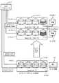
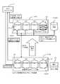
図1〜図9に基づいて、本発明の第1実施例を説明する。図1は、ディスクアレイ装置10の概略構成を示すブロック図である。
ディスクアレイ装置10は、通信ネットワークCN1を介して、複数のホストコンピュータ1と双方向通信可能に接続されている。ここで、通信ネットワークCN1は、例えば、LAN(Local Area Network)、SAN(Storage Area Network)、インターネット等である。LANを用いる場合、ホストコンピュータ1とディスクアレイ装置10との間のデータ転送は、TCP/IP(Transmission
Control Protocol/Internet Protocol)プロトコルに従って行われる。SANを用いる場合、ホストコンピュータ1とディスクアレイ装置10とは、ファイバチャネルプロトコルに従ってデータ転送を行う。また、ホストコンピュータ1がメインフレームの場合は、例えば、FICON(Fibre
Connection:登録商標)、ESCON(Enterprise
System Connection:登録商標)、ACONARC(Advanced
Connection Architecture:登録商標)、FIBARC(Fibre
Connection Architecture:登録商標)等の通信プロトコルに従ってデータ転送が行われる。A first embodiment of the present invention will be described with reference to FIGS. FIG. 1 is a block diagram showing a schematic configuration of the
The
Control Protocol / Internet Protocol). When SAN is used, the
Connection: registered trademark), ESCON (Enterprise
System Connection: registered trademark), ACONARC (Advanced
Connection Architecture: registered trademark, FIBARC (Fibre
Data transfer is performed according to a communication protocol such as Connection Architecture (registered trademark).
各ホストコンピュータ1は、例えば、サーバ、パーソナルコンピュータ、ワークステーション、メインフレーム等として実現されるものである。例えば、各ホストコンピュータ1は、図外に位置する複数のクライアント端末と別の通信ネットワークを介して接続されている。各ホストコンピュータ1は、例えば、各クライアント端末からの要求に応じて、ディスクアレイ装置10にデータの読み書きを行うことにより、各クライアント端末へのサービスを提供する。 Each
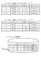
ディスクアレイ装置10は、それぞれ後述するように、各チャネルアダプタ(以下、CHAと略記)11と、各ディスクアダプタ(以下、DKAと略記)12と、共有メモリ13と、キャッシュメモリ14と、スイッチ部15と、各ディスクドライブ16とを備えて構成されている。CHA11及びDKA12は、例えば、プロセッサやメモリ等が実装されたプリント基板と、制御プログラムとの協働により実現される。 As will be described later, the
ディスクアレイ装置10には、例えば、4個や8個等のように、複数のCHA11が設けられている。チャネルアダプタ11は、例えば、オープン系用CHA、メインフレーム系用CHA等のように、ホストコンピュータ1の種類に応じて、用意される。各CHA11は、ホストコンピュータ1との間のデータ転送を制御するものである。各CHA11は、それぞれプロセッサ部、データ通信部及びローカルメモリ部を備えている(いずれも不図示)。 The
各CHA11は、それぞれに接続されたホストコンピュータ1から、データの読み書きを要求するコマンド及びデータを受信し、ホストコンピュータ1から受信したコマンドに従って動作する。DKA12の動作も含めて先に説明すると、例えば、CHA11は、ホストコンピュータ1からデータの読出し要求を受信すると、読出しコマンドを共有メモリ13に記憶させる。DKA12は、共有メモリ13を随時参照しており、未処理の読出しコマンドを発見すると、ディスクドライブ16からデータを読み出して、キャッシュメモリ14に記憶させる。CHA11は、キャッシュメモリ14に移されたデータを読み出し、コマンド発行元のホストコンピュータ1に送信する。また例えば、CHA11は、ホストコンピュータ1からデータの書込み要求を受信すると、書込みコマンドを共有メモリ13に記憶させると共に、受信データをキャッシュメモリ14に記憶させる。DKA12は、共有メモリ13に記憶されたコマンドに従って、キャッシュメモリ14に記憶されたデータを所定のディスクドライブ16に記憶させる。 Each
各DKA12は、ディスクアレイ装置10内に例えば4個や8個等のように複数個設けられている。各DKA12は、各ディスクドライブ16との間のデータ通信を制御するもので、それぞれプロセッサ部と、データ通信部と、ローカルメモリ等を備えている(いずれも不図示)。各DKA12と各ディスクドライブ16とは、例えば、SAN等の通信ネットワークCN2を介して接続されており、ファイバチャネルプロトコルに従ってブロック単位のデータ転送を行う。各DKA12は、ディスクドライブ16の状態を随時監視しており、この監視結果は内部ネットワークCN3を介してSVP2に送信される。 A plurality of DKAs 12 are provided in the
ディスクアレイ装置10は、多数のディスクドライブ16を備えている。ディスクドライブ16は、例えば、ハードディスクドライブ(HDD)や半導体メモリ装置等として実現される。ここで、例えば、4個のディスクドライブ16によってRAIDグループ17を構成することができる。RAIDグループ17とは、例えばRAID5(RAID5に限定されない)に従って、データの冗長記憶を実現するディスクグループである。各RAIDグループ17により提供される物理的な記憶領域の上には、論理的な記憶領域である論理ボリューム18(LU)を少なくとも1つ以上設定可能である。 The
「制御メモリ」の一例に該当する共有メモリ13は、例えば、不揮発メモリによって構成されており、制御情報や管理情報等を記憶する。キャッシュメモリ14は、主としてデータを記憶する。 The shared
SVP(Service Processor)2は、ディスクアレイ装置10の管理及び監視を行うためのコンピュータ装置である。SVP2は、ディスクアレイ装置10内に設けられた通信ネットワークCN3を介して、各CHA11及び各DKA12等から各種の環境情報や性能情報等を収集する。SVP2が収集する情報としては、例えば、装置構成、電源アラーム、温度アラーム、入出力速度(IOPS)等が挙げられる。通信ネットワークCN3は、例えば、LANとして構成される。システム管理者は、SVP2の提供するユーザインターフェースを介して、RAID構成の設定、各種パッケージ(CHA、DKA、ディスクドライブ等)の閉塞処理等を行うことができる。 The SVP (Service Processor) 2 is a computer device for managing and monitoring the
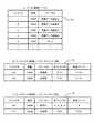
図2は、ディスクアレイ装置10内に記憶されるRAID構成管理テーブルT1の概略構造を示す説明図である。RAID構成管理テーブルT1は、例えば共有メモリ13内に記憶される。RAID構成管理テーブルT1は、例えば、RAIDグループ番号(図中、グループ#)と、論理ボリューム番号(図中、ボリューム#)と、ディスクドライブ番号(図中、ディスク#)と、RAIDレベルとを対応付けている。以下に述べる他のテーブルも同様であるが、テーブル内の文字または数値は、説明のためのものであって、実際に記憶されるものとは異なる。RAID構成管理テーブルT1の内容の一例を説明すると、例えば、グループ番号1のRAIDグループ17には、ボリューム番号1〜3の合計3個の論理ボリューム18が設定されている。また、このRAIDグループ17は、ディスク番号1〜4で特定される合計4個のディスクドライブ16から構成されている。そして、このグループ番号1で特定されるRAIDグループ17は、RAID5に従って運用されている。 FIG. 2 is an explanatory diagram showing a schematic structure of the RAID configuration management table T1 stored in the
本実施例では、後述のように、あるディスクドライブ16に障害発生の予兆が検出された場合、この障害発生が予測されるディスクドライブ16が所属するRAIDグループへのデータ書込みを、他のRAIDグループ(あるいは、論理ボリュームやディスクドライブ)に退避させるようになっている。 In this embodiment, as described later, when a failure occurrence is detected in a
図2(a)は、退避用のRAIDグループ17を設定する前の構成を示し、図2(b)は、退避用のRAIDグループ17を設定した後の構成を示す。図2(a)に示すように、グループ番号5で特定されるRAIDグループ17は、当初使用目的が設定されておらず、論理ボリュームが1つも設定されていない。グループ番号1のRAIDグループ17に属するいずれか1つのディスクドライブ16に障害の発生が予測されると、グループ番号5で特定される未使用のRAIDグループ17は、退避用のRAIDグループ17として利用される。データ退避用に使用されるRAIDグループ17(#5)には、データ退避元のRAIDグループ17(#1)に設定されている論理ボリューム18(#1〜3)と同数の論理ボリューム(#13〜15)が設定される。 FIG. 2A shows a configuration before setting the
図3は、ディスクアレイ装置10内に記憶されるペア情報管理テーブルT2の概略構造を示す説明図である。ペア情報管理テーブルT2は、例えば、共有メモリ13内に記憶されるもので、ペアを構成する論理ボリューム18について管理する。 FIG. 3 is an explanatory diagram showing a schematic structure of the pair information management table T2 stored in the
ペア情報管理テーブルT2は、例えば、正ボリューム番号と、副ボリューム番号と、ペア状態と、差分ビットマップとを対応付けている。図3(a)に示すペア情報管理テーブルT2は、データ退避用の論理ボリューム18を設定する前の状態を示している。図3(a)では、例えば、ある1つの論理ボリューム18(#4)が正、別の1つの論理ボリューム18(#7)が副となってペアを構成している。ペア状態は「二重化」である。二重化とは、正ボリュームと副ボリュームとの記憶内容を同期させることを意味する。差分ビットマップについてはさらに後述するが、正ボリュームと副ボリュームとのデータの差分を管理するための情報である。 In the pair information management table T2, for example, a primary volume number, a secondary volume number, a pair status, and a difference bitmap are associated with each other. The pair information management table T2 shown in FIG. 3A shows a state before setting the
図3(b)は、データ退避用のRAIDグループ17を設定した場合を示す。RAIDグループ17(#1)の各論理ボリューム18(#1〜3)は、RAIDグループ17(#5)に設定された各論理ボリューム18(#13〜15)にそれぞれ一対一で対応付けられる。即ち、図3(b)に示す例では、論理ボリューム18(#1)は、論理ボリューム18(#13)とペアを構成し、論理ボリューム18(#2)は、論理ボリューム18(#14)とペアを構成し、論理ボリューム18(#3)は、論理ボリューム18(#15)とペアを構成する。これらの各ペアのペア状態は、「二重化」ではなく、「更新データ退避中」となっている。「更新データ退避中」とは、データ退避元の論理ボリューム18(#1〜3)を対象とする更新データを、データ退避先の論理ボリューム18(#13〜15)に退避させている状態を示す。「更新データ退避中」状態と、「二重化」状態とでは、例えば、初期コピーを行わない点で相違する。通常の二重化では、最初に初期コピーを行って、正ボリュームと副ボリュームとの内容を一致させるが、「更新データ退避中」状態では、初期コピーを行わない。 FIG. 3B shows a case where a
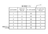
図4は、差分ビットマップ20について説明する説明図である。図4(a)に示すように、本実施形態では、正ボリュームと副ボリュームとでペアを形成し、正ボリュームへデータ書込み(更新)が要求された場合は、このデータを副ボリュームに記憶させるようになっている。仮に、データ(#1)とデータ(#2)の更新があった場合、これらのデータは、副ボリュームに記憶される。そして、更新データに対応する差分ビットには、それぞれ「1」がセットされる。差分ビットに「1」がセットされた状態は、副ボリューム内のデータが正ボリュームに反映されていないこと、即ち、新たなデータが副ボリュームに記憶されていることを意味する。従って、データ読出し要求があった場合、要求されたデータに対応する差分ビットが「1」にセットされているならば、そのデータは、副ボリュームに記憶されていると判別することができる。逆に、読出し対象のデータに対応する差分ビットが「0」にセットされているならば、要求されたデータは、正ボリュームに記憶されていると判別することができる。 FIG. 4 is an explanatory diagram for explaining the
図4(b)に示すように、差分ビットマップ20は、差分ビットの集合体である。差分ビットマップ20は、「差分管理情報」の一例である。本実施例において、各差分ビットは、ディスクの各トラックにそれぞれ対応している。従って、更新管理単位は、トラック単位である。更新管理単位に満たないデータの更新がされた場合は、この更新データが属するトラックの全データをキャッシュメモリ14に読出し、キャッシュメモリ14上で更新データと合成させる。そして、このキャッシュメモリ14上で合成されたトラックを副ボリュームに記憶させ、対応する差分ビットを「1」にセットする。 As shown in FIG. 4B, the
次に、図5は、本実施例による障害回避方法の全体概要を示す説明図である。図5に示す例では、RAIDグループ17(P)に属する4番目のディスクドライブ16(#4)に障害発生が予測されたものとする。詳細は後述するが、読出しエラーや書込みエラーが所定の閾値以上に発生した場合、このディスクドライブ16(#4)は、障害発生のおそれありと判定される。そこで、まず最初に、障害発生が予測されたディスクドライブ16(#4)の記憶内容がキャッシュメモリ14に読み出され、キャッシュメモリ14から予備ディスクドライブ16(SP)にコピーされる(S1)。 Next, FIG. 5 is an explanatory diagram showing an overall outline of the failure avoidance method according to the present embodiment. In the example shown in FIG. 5, it is assumed that a failure has been predicted for the fourth disk drive 16 (# 4) belonging to the RAID group 17 (P). As will be described in detail later, if a read error or write error occurs above a predetermined threshold, this disk drive 16 (# 4) is determined to have a possibility of failure. Therefore, first, the storage contents of the disk drive 16 (# 4) where the failure has been predicted are read out to the
予備ディスクドライブ16(SP)へのデータコピーが開始されると、ディスクアレイ装置10が有する複数のRAIDグループ17のうち、未使用のRAIDグループが1つ確保される(S2)。そして、障害発生が予測されたディスクドライブ16(#4)の属するRAIDグループ17(P)を正、S2で確保された未使用のRAIDグループ17(S)を副として、ペアが形成される。正のRAIDグループ17(P)に設定されている正ボリューム18(P)と、副のRAIDグループ17(S)に設定される副ボリューム18(S)とは、ペアを形成する(S3)。このペアに関する情報は、ペア情報管理テーブルT2に登録される。 When data copy to the spare disk drive 16 (SP) is started, one unused RAID group is secured among the plurality of
予備ディスクドライブ16(SP)へのデータ移行中に、ホストコンピュータ1からデータ書込みが要求された場合、このデータは、正ボリューム18(P)ではなく、副ボリューム18(S)に記憶される(S4)。副ボリューム18(S)にデータが記憶された場合、この更新データに対応する差分ビットが「1」にセットされ、差分ビットマップ20により管理される(S5)。 If data write is requested from the
予備ディスクドライブ16(SP)へのデータ移行中に、ホストコンピュータ1からデータ読出しが要求された場合、DKA12は、差分ビットマップ20を参照することにより、ホストコンピュータ1から要求されたデータが正ボリューム18(P)と副ボリューム18(S)のいずれに記憶されているかを判別する。要求されたデータに対応する差分ビットが「0」にセットされている場合、この要求されたデータは、正ボリューム18(P)に記憶されている。そこで、DKA12は、要求されたデータを正ボリューム18(P)から読み出し、キャッシュメモリ14にコピーする。CHA11は、キャッシュメモリ14に移されたデータを、ホストコンピュータ1に送信する(S6)。一方、ホストコンピュータ1から要求されたデータに対応する差分ビットが「1」にセットされている場合、この要求されたデータは、副ボリューム18(S)に存在する。そこで、DKA12は、要求されたデータを副ボリューム18(S)から読み出してキャッシュメモリ14にコピーする。前記同様に、CHA11は、キャッシュメモリ14に移されたデータをホストコンピュータ1に送信する(S7)。 When data reading is requested from the
予備ディスク16(SP)へのデータ移行が完了すると、DKA12は、差分ビットマップ20を参照し、副ボリューム18(S)に退避したデータを、正ボリューム18(P)側に反映させる(S8)。より詳しくは、副ボリューム18(S)に記憶されたデータは、正のRAIDグループ17(P)に属するディスクドライブ16のうち、障害が予測されたディスクドライブ16(#4)以外のディスクドライブ16(#1〜3)と、予備ディスクドライブ16(SP)とにコピーされる。言うまでもないが、副ボリューム18(S)に記憶されたデータの全部をディスクドライブ16(#1〜3)及び予備ディスクドライブ(SP)にそれぞれコピーするのではない。対応するディスクにのみ必要なデータがコピーされる。 When the data migration to the spare disk 16 (SP) is completed, the
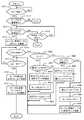
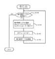
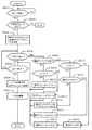
次に、図5中のS1で示した予備ディスクドライブ16(SP)へのコピー処理について、図6を参照しつつ説明する。本実施例においては、予備ディスクドライブ16(SP)へのデータコピーを「スペアリング」と称する場合がある。図6に示すフローチャートは、「第1制御部」、「第1ステップ」及び「第2ステップ」、「障害ドライブ検出ステップ」及び「データコピーステップ」の一例である。図6に示す処理は、例えば、DKA12によって実行される。なお、以下の各フローチャートでも同様であるが、各フローチャートは処理の概要を示すもので、実際のコンピュータプログラムとは相違する。 Next, the copy process to the spare disk drive 16 (SP) indicated by S1 in FIG. 5 will be described with reference to FIG. In the present embodiment, data copying to the spare disk drive 16 (SP) may be referred to as “sparing”. The flowchart shown in FIG. 6 is an example of “first control unit”, “first step” and “second step”, “failed drive detection step”, and “data copy step”. The process shown in FIG. 6 is executed by the
DKA12は、各ディスクドライブ16におけるアクセスエラー(IOエラー)を監視している(S11)。エラー発生が検出された場合(S11:YES)、DKA12は、エラー種別毎にエラー発生回数を管理する(S12)。DKA12は、例えば、図6中に示すエラー管理テーブルT3を用いることにより、発生したアクセスエラーを管理することができる。アクセスエラーは、その種類(ET1〜ET3・・・)毎に発生回数(N1〜N3・・・)が管理され、かつ、アクセスエラーの種類毎に閾値Th1〜Th3・・・がそれぞれ設定されている。図6中では1つだけ図示するが、エラー管理は、使用されている各ディスクドライブ16毎にそれぞれ行われる。 The
ここで、アクセスエラーは、例えば、読出しエラーと書込みエラーとに分類することができる。また、アクセスエラーは、例えば、リカバリ可能なエラーとリカバリ不能なエラーとに分類することもできる。リカバリ可能なエラーとは、例えば、ECC(Error-Correcting Code)によりデータの修復を容易に行える種類のエラーを意味する。リカバリ不能なエラーとは、各データに付加された冗長データ(ECC)ではエラーを修復することができず、より上位での回復(他のデータとパリティとによる逆演算等)が必要となる種類のエラーを意味する。アクセスエラーの具体例としては、例えば、ディスク面に物理的な傷が存在するためにデータを書き込むことができない場合、ディスク面の磁性が劣化しているためデータを読み出すことができない場合、磁気ヘッドの不良でデータの読み書きができない場合等を挙げることができる。 Here, the access error can be classified into, for example, a read error and a write error. Further, access errors can be classified into recoverable errors and unrecoverable errors, for example. The recoverable error means, for example, an error of a type that can easily restore data by ECC (Error-Correcting Code). An unrecoverable error is a type in which redundant data (ECC) added to each data cannot be repaired, and higher-level recovery (such as reverse operation using other data and parity) is required. Means an error. As specific examples of access errors, for example, when data cannot be written because there is a physical flaw on the disk surface, when data cannot be read because the magnetism of the disk surface has deteriorated, the magnetic head For example, it is possible to read / write data due to a defect.
エラー管理テーブルT3の下側に示すように、リカバリ可能なエラーとリカバリ不能なエラーとでは、閾値Thの設定値が異なる。リカバリ可能なエラーの閾値Thは、相対的に高く設定され、リカバリ不能なエラーの閾値Thは、相対的に低く設定される。なお、図6中のエラー管理テーブルT3では、3種類以上のエラーを示し、各種類のエラー毎にそれぞれ閾値Thを設定しているが、これは一例であって、リカバリ可能エラー及びリカバリ不能エラーの2種類に限定してもよい。あるいは、さらに詳しくエラーを分類し、エラー管理テーブルT3に示すように、多種類のエラー毎にそれぞれ閾値Thを設定するようにしてもよい。 As shown below the error management table T3, the set value of the threshold Th is different for recoverable errors and unrecoverable errors. The recoverable error threshold Th is set relatively high, and the unrecoverable error threshold Th is set relatively low. In the error management table T3 in FIG. 6, three or more types of errors are shown, and a threshold value Th is set for each type of error. This is an example, and a recoverable error and an unrecoverable error are shown. You may limit to these two types. Alternatively, errors may be classified in more detail, and a threshold value Th may be set for each of various types of errors as shown in the error management table T3.
DKA12は、エラー管理テーブルT3を参照することにより、使用されているディスクドライブ16のそれぞれについて、アクセスエラーの発生頻度が閾値Th以上になったか否かを判定する(S13)。アクセスエラーの発生頻度が閾値Th以上になっていない場合は(S13:NO)、処理を終了する。一方、アクセスエラーの発生頻度が閾値Th以上になった場合は(S13:YES)、そのディスクドライブ16に障害の発生が予測された場合である。そこで、DKA12は、障害の発生が予測されたディスクドライブ(以下、このドライブを障害ディスクドライブと称する場合がある)16の記憶内容を、予備ディスクドライブ16(SP)にコピーし、データ移行を開始させる(S14)。データ移行が完了するまで(S15:NO)、S14の処理が繰り返される。予備ディスクドライブ16(SP)へのデータ移行が完了すると(S15:YES)、処理を終了する。 The
なお、上記処理では、エラー種別毎にそれぞれ閾値Thを設定し、いずれかの種類のアクセスエラーの発生頻度が、それに対応する閾値Th以上になった場合に、障害ディスクドライブであると判定している。しかし、これに限らず、アクセスエラーを総合的に解析することにより(アクセスエラーに基づいて)、障害ディスクドライブであるか否かを判定してもよい。 In the above processing, a threshold value Th is set for each error type, and when the frequency of occurrence of any type of access error is equal to or higher than the corresponding threshold value Th, it is determined that the disk drive is a failed disk drive. Yes. However, the present invention is not limited to this, and it may be determined whether or not it is a failed disk drive by comprehensively analyzing the access error (based on the access error).
図7は、SVP2を介して、手動操作によりスペアリングを実行させる場合の処理を示す。図7に示す処理は、主としてSVP2とDKA12との協働作業により実行される。この処理は、「手動指示部」に対応する構成を含んでいる。 FIG. 7 shows a process in the case of performing sparing by manual operation via the SVP2. The process shown in FIG. 7 is mainly executed by the cooperative work between the
SVP2は、内部ネットワークCN3を介して、各DKA12から各ディスクドライブ16に関するエラー情報を収集している(S21)。SVP2は、システム管理者からの要求に応じて、あるいは自動的に、収集したエラー情報をSVP2の端末画面に表示させる(S22)。SVP2は(より正確には、SVP2のマイクロプロセッサにより実行される制御プログラムは)、各ディスクドライブ16のそれぞれについて、アクセスエラーの発生頻度が閾値Th以上になったか否かを判定する(S23)。アクセスエラーの発生頻度が閾値Th以上になったディスクドライブ16が検出された場合(S23:YES)、SVP2は、このディスクドライブ16を将来障害の発生する可能性が高い障害ディスクドライブであると判定し、システム管理者に警告する(S24)。この警告は、例えば、警告メッセージの表示または音声出力、警告ランプの点滅等により行うことができる。アクセスエラーの発生頻度が閾値Th以上になったディスクドライブ16が存在しない場合(S23:NO)、S24はスキップされる。 The
システム管理者は、S24で通知された警告に従って、あるいは、警告がされていない場合でも自らの判断に従って、スペアリングの開始を指示できる。システム管理者からの手動操作によるスペアリング開始指示は、SVP2のユーザインターフェース(例えば、キーボードスイッチからの入力や音声による指示等)により行われる。DKA12は、システム管理者からのスペアリングの開始指示があったか否かを判定する(S25)。手動操作による開始指示が無い場合(S25:NO)、処理を終了するか否かを判定する(S26)。例えば、システム管理者がメニュー操作等を行うことにより処理の終了を指示した場合(S26:YES)、処理は終了する。システム管理者が処理の終了を指示しない場合(S26:NO)、S21に戻ってエラー情報の収集等が繰り返される。 The system administrator can instruct the start of sparing according to the warning notified in S24 or according to his / her own judgment even when no warning is given. A sparing start instruction by a manual operation from the system administrator is performed by a user interface of the SVP 2 (for example, an input from a keyboard switch or an instruction by voice). The
システム管理者の手動操作によってスペアリングの開始が指示された場合(S25:YES)、システム管理者により指示されたディスクドライブ16またはS24で警告されたディスクドライブ16、あるいはシステム管理者により指示されたディスクドライブ16及び警告されたディスクドライブ16の記憶内容が、予備ディスクドライブ16(SP)にコピーされる(S27)。そして、予備ディスクドライブ16(SP)へのデータ移行が完了すると(S28:YES)、処理を終了する。 When the start of sparing is instructed by the manual operation of the system administrator (S25: YES), the
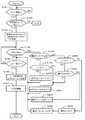
図8は、データ退避処理を示すフローチャートである。データ退避処理は、スペアリングの開始により起動されるもので、DKA12によって実行される。図8に示す処理は、「第2制御部」、「第3ステップ」〜「第5ステップ」、「アクセス要求検出ステップ」及び「アクセス処理ステップ」にそれぞれ対応する一例である。 FIG. 8 is a flowchart showing the data saving process. The data saving process is activated by the start of sparing and is executed by the
DKA12は、スペアリング、即ち、障害ディスクドライブ16から予備ディスクドライブ16(SP)へのデータコピーが開始されたか否かを監視している(S31)。スペアリング開始が検出されると(S31:YES)、DKA12は、未使用のRAIDグループ17が存在するか否かを判定する(S32)。未使用のRAIDグループ17が存在しない場合(S32:NO)、データ退避領域を確保できないので、処理を終了する。 The
未使用のRAIDグループ17を発見した場合(S32:YES)、DKA12は、障害ディスクドライブ16が属するRAIDグループ17を正、発見された未使用のRAIDグループ17を副として、ペアを構成する(S33)。正のRAIDグループ17に複数の論理ボリューム18が設定されている場合、副のRAIDグループ17にも同数かつ同サイズの論理ボリューム18がそれぞれ設定され、正と副の各論理ボリューム18同士でペアが形成される。 When an
DKA12は、随時共有メモリ13を参照することにより、ホストコンピュータ1からのアクセス要求(読出し要求または書込み要求)が発生したか否かを監視している(S34)。ホストコンピュータ1からのアクセス要求が発生していない場合(S34:NO)、DKA12は、スペアリングが終了したか否かを判定する(S35)。スペアリングが終了していない場合(S35:NO)、S34に戻る。スペアリングが終了した場合(S35:YES)、DKA12は、副ボリューム18に記憶されたデータを、正ボリューム18に反映させ(S36)、ボリュームペアを解除し(S37)、処理を終了する。 The
スペアリング中にホストコンピュータ1からのアクセス要求が発生した場合(S34:YES)、DKA12は、このアクセス要求が読出し要求(図中、リードと表示)であるか否かを判定する(S38)。読出し要求である場合(S38:YES)、DKA12は、差分ビットマップ20を参照し、読出しを要求されたデータに対応する差分ビットに「1」がセットされているか否か(図中では、差分ビットに1をセットする場合をON、差分ビットに0をセットする場合をOFFと示す)を判定する(S39)。 When an access request from the
差分ビットに「1」がセットされている場合(S39:YES)、要求されたデータは副ボリューム18に存在する。そこで、DKA12は、副ボリューム18からデータを読み出して、キャッシュメモリ14に格納する(S40)。読出しを要求されたデータに対応する差分ビットに「0」がセットされている場合(S39:NO)、要求されたデータは正ボリューム18に存在するので、DKA12は、正ボリューム18からデータを読み出し、キャッシュメモリ14に格納する(S41)。ここで、要求されたデータが障害ディスクドライブ16に記憶されている場合は、障害ディスクドライブ16から直接データを読み出すのではなく、他の正常なディスクドライブ16に格納されているデータに基づいて、要求されたデータを復元する。 When “1” is set in the difference bit (S39: YES), the requested data exists in the
ホストコンピュータ1からのアクセス要求が書込み要求である場合(S38:NO)、DKA12は、書込みデータ(更新データ)に対応する差分ビットに「1」をセットし(S42)、書込みデータを副ボリューム18に記憶させる(S43)。 If the access request from the
図9は、差分データのフィードバック処理を示すフローチャートである。差分データフィードバック処理は、スペアリングの終了により、DKA12によって実行される。本処理は、図8中のS36の詳細である。本処理は、「第3制御部」、「第6ステップ」、「データ更新ステップ」に対応する一例である。 FIG. 9 is a flowchart showing the difference data feedback processing. The differential data feedback process is executed by the
DKA12は、フィードバックポインタを論理ボリュームの先頭アドレスにセットする(S51)。DKA12は、そのアドレスに対応する差分ビットに「1」がセットされているか否かを判定する(S52)。差分ビットに「1」がセットされている場合(S52:YES)、DKA12は、そのアドレスのデータを副ボリューム18から正ボリューム18にコピーさせる(S53)。より詳しくは、副ボリューム18から読み出されたデータは、キャッシュメモリ14にコピーされ、キャッシュメモリ14から正ボリューム18にコピーされる。1アドレス分のデータコピーを終了すると、DKA12は、フィードバックポインタを次のアドレスに移動させる(S54)。そして、DKA12は、差分データのフィードバックが完了したか否かを判定する(S55)。即ち、DKA12は、フィードバックポインタが最終位置を示しているか否かを判定する。差分データのフィードバックが完了するまで(S55:NO)、S52〜S54の処理が繰り返し実行される。 The
このように構成される本実施例によれば、以下の効果を奏する。
障害ディスクドライブ(正確には、障害の発生が予測されるディスクドライブ)16から予備ディスクドライブ16(SP)へのデータ移行中に、障害ディスクドライブ16の属するRAIDグループ17へのデータ読み書きを低減することができる。従って、RAIDグループ17を構成する他の正常なディスクドライブ16に障害が発生する可能性を少なくすることができ、いわゆる二重障害の可能性を低減できる。即ち、例えば、RAID5に従う一組のデータセットを考えた場合、このデータセットを構成するいずれか1つのデータが失われた場合でも、残りのデータ(パリティを含む)から逆演算を行うことにより、消失したデータを復元することができる。具体的には、例えば、データセットが、D1〜D4の4個のデータと1個のパリティpとから構成される場合を考える。仮に、D2の読出しを行うことができない場合、D2は、D2=(D1)XOR(D3)XOR(D4)XOR(p)よって求めることができる。しかし、2つ以上のデータが利用できない場合、演算によるデータ復元は不可能である。According to this embodiment configured as described above, the following effects can be obtained.
During data migration from the failed disk drive (to be exact, a disk drive in which a failure is predicted) 16 to the spare disk drive 16 (SP), data read / write to the
障害ディスクドライブ16であると判定されていない他の正常なディスクドライブ16であっても、全くエラーが存在しないとは限らない。また、エラーが全く存在しない場合でも、アクセス回数が多くなればなるほどエラーを生じる確率が増す。もしも、正常なディスクドライブ16に発生したエラーの位置が、障害ディスクドライブ16のエラー位置と偶然一致した場合、その場所に格納されているデータを復元することはできない。障害ディスクドライブ16には比較的多数のエラーが既に生じているので、正常なディスクドライブ16に追加的に発生した新たなエラーの位置が、障害ディスクドライブ16のエラー位置と偶然一致するおそれがある。このようなエラー位置の一致による障害を本実施例では「二重障害」と呼ぶ。従って、スペアリングの最中に、正常なディスクドライブ16へのアクセスを通常通り続行すると、正常なディスクドライブ16に生じた新たなエラーによって、データの一部を消失する可能性がある。 Even if another
これに対し、本実施例では、スペアリング中に、正常な他のディスクドライブ16へのアクセスを低減するため、正常な他のディスクドライブ16に新たなエラーが追加的に発生して、二重障害が発生する可能性を少なくできる。具体的には、本実施例では、スペアリング中におけるデータ書込みは、副ボリューム18に対して行わせ、スペアリング中のデータの読出しは、要求されたデータが正ボリューム18に存在する場合に限って、正ボリューム18から読み出す。従って、障害ディスクドライブ16が属する正ボリューム18へのアクセス頻度を低減し、二重障害の発生を防止可能である。 On the other hand, in the present embodiment, in order to reduce access to other
また、本実施例では、副ボリューム18に退避させたデータを差分ビットマップ20によって管理する。従って、ホストコンピュータ1からデータの読出し要求があった場合に、要求されたデータが正ボリューム18または副ボリューム18のいずれに存在するかを容易に判別することができる。 In this embodiment, the data saved in the
図10〜図13に基づいて、本発明の第2実施例を説明する。本実施例の1つの特徴は、スペアリング中のデータ退避領域として、論理ボリュームを使用する点にある。また、本実施例の1つの特徴は、ジャーナルファイルを使用する点にある。図10は、本実施例による障害回避方法の全体動作の概要を示す説明図である。動作全体の概要は、前記実施例とほぼ同様である。 A second embodiment of the present invention will be described with reference to FIGS. One feature of this embodiment is that a logical volume is used as a data saving area during sparing. One feature of the present embodiment is that a journal file is used. FIG. 10 is an explanatory diagram showing an overview of the overall operation of the failure avoidance method according to this embodiment. The outline of the entire operation is almost the same as that of the above embodiment.
あるディスクドライブ16について障害の発生が予測されると、この障害発生が予測されたディスクドライブ16の記憶内容を予備ディスクドライブ16(SP)に移行させるスペアリングが開始される(S61)。スペアリングが開始されると、データ退避領域用に、未使用の論理ボリューム18が少なくとも1つ以上確保される(S62)。この未使用の論理ボリューム18は、ワークボリューム18(W)として利用される。ここで、注意すべき点は、前記実施例とは異なり、同サイズの未使用RAIDグループを確保するのではなく、未使用の論理ボリュームを確保する点である。即ち、データ退避元の記憶サイズとデータ退避先の記憶サイズとが相違し、データ退避元よりも小さな記憶サイズを有するデータ退避先を使用する点である。 When the occurrence of a failure is predicted for a
データ退避元のRAIDグループ17(P)に設定された論理ボリューム18(P)と、ワークボリューム18(W)とが対応付けられる(S63)。論理ボリューム18(P)とワークボリューム18(W)とは、記憶サイズが異なってもよい(同一サイズであってもよい)。ホストコンピュータ1からRAIDグループ17(P)に対する書込み要求が発生すると、この更新データは、ワークボリューム18(W)に順次記憶されていく(S64)。ここで注意すべき点は、ワークボリューム18(W)には、ジャーナルファイルのように、書込みの履歴が記憶される点である。 The logical volume 18 (P) set in the data saving source RAID group 17 (P) is associated with the work volume 18 (W) (S 63). The logical volume 18 (P) and the work volume 18 (W) may have different storage sizes (may be the same size). When a write request from the
ホストコンピュータ1からRAIDグループ17(P)に対する読出し要求が発生した場合、要求されたデータがRAIDグループ17(P)に存在するならば、つまり、更新されていないデータの読出し要求の場合は、論理ボリューム18(P)からデータが読み出され、キャッシュメモリ14及びCHA11等を介して、ホストコンピュータ1に提供される(S65)。要求されたデータが障害ディスクドライブ16(#4)に存在する場合、他のディスクドライブ16(#1〜3)が記憶するデータに基づいて、要求されたデータが復元される。 When a read request from the
ホストコンピュータ1から要求されたデータがワークボリューム18(W)に存在するならば、つまり、更新されたデータの読出し要求の場合は、ワークボリューム18(W)からデータが読み出され、ホストコンピュータ1に提供される(S66)。そして、スペアリングが終了すると、ワークボリューム18(W)に記憶されたデータが、論理ボリューム18(P)及び予備ディスクドライブ16(SP)に反映される(S67)。障害ディスクドライブ16(#4)に差分データは反映されない。 If the data requested from the
図11は、ディスクアレイ装置10内に記憶されるワークボリューム管理テーブルT4の概略構造を示す説明図である。ワークボリューム管理テーブルT4は、例えば、共有メモリ13内に記憶される。なお、前記実施例で述べた各テーブルも含めて、全てのテーブルは、共有メモリ以外の記憶領域に記憶させることもできる。 FIG. 11 is an explanatory diagram showing a schematic structure of the work volume management table T4 stored in the
ワークボリューム管理テーブルT4は、例えば、ワークボリューム番号と、ワークボリュームの記憶容量と、対応付けられている正ボリュームの番号と、最新のデータ更新を記憶する終端アドレスと、差分ビットマップとを対応付けて構成されている。差分ビットマップは、更新されたデータの位置を管理するために用いられる。図11(a)は、予備ディスクドライブ16(SP)へのデータ移行(スペアリング処理)が開始される前の状態を示す。従って、3個のワークボリューム18(#10〜12)は、いずれも正ボリュームに対応付けられていない。 The work volume management table T4 associates, for example, the work volume number, the storage capacity of the work volume, the associated primary volume number, the end address storing the latest data update, and the differential bitmap. Configured. The difference bitmap is used to manage the location of updated data. FIG. 11A shows a state before data migration (sparing processing) to the spare disk drive 16 (SP) is started. Accordingly, none of the three work volumes 18 (# 10 to 12) is associated with the primary volume.
図11(b)は、スペアリング処理が開始された後の状態を示す。この例では、各ワークボリューム18(#10〜12)を、それぞれ1つずつの正ボリューム18(#1〜3)に対応付けている。しかし、これに限らず、1つのワークボリューム18を複数の正ボリューム18に対応付ける構成でもよい。 FIG. 11B shows a state after the sparing process is started. In this example, each work volume 18 (# 10-12) is associated with one primary volume 18 (# 1-3). However, the present invention is not limited to this, and one
図11(c)は、ワークボリューム18に記憶されるデータの概略構造を示す。ワークボリューム18内では、例えば、ジャーナルアドレスと、正ボリューム番号と、アドレスと、更新データとが対応付けられて記憶されている。図示の例では、上から順番にデータが記憶されていくようになっており、最下端が終端アドレスとなっている。 FIG. 11C shows a schematic structure of data stored in the
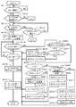
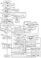
図12は、データ退避処理を示すフローチャートである。本処理は、DKA12によって実行される。DKA12は、障害ディスクドライブ16から予備ディスクドライブ16(SP)へのデータコピーが開始されたことを検出すると(S71)、ワークボリューム18が登録されているか否かを判定する(S72)。ワークボリューム18が登録されていない場合(S72:NO)、データ退避領域を確保できないので処理を終了する。 FIG. 12 is a flowchart showing the data saving process. This process is executed by the
ワークボリューム18が登録されている場合(S72:YES)、登録されているワークボリューム18が未使用であるか否かを判定する(S73)。そのワークボリューム18が使用中の場合(S73:NO)、他にワークボリューム18が登録されているか否かを判定する(S74)。登録済のワークボリュームが存在しない場合(S74:NO)、データ退避領域を確保できないので処理を終了する。一方、他のワークボリューム18が登録されている場合(S74:YES)、S73に戻って未使用のワークボリューム18であるか否かを検査する。 When the
このようにして、DKA12は、登録されているワークボリューム18を順番に検査し、未使用のワークボリューム18を検出する。未使用のワークボリューム18が検出された場合(S73:YES)、DKA12は、この検出された未使用のワークボリューム18とデータ退避元の論理ボリューム18とを対応付けて、ワークボリューム管理テーブルT4に登録する(S75)。 In this way, the
DKA12は、予備ディスクドライブ16(SP)へのデータ移行が完了するまでの期間(S77)、ホストコンピュータ1からのアクセス要求が発生したか否かを監視する(S76)。データ移行が完了した場合(S78:YES)、DKA12は、ワークボリューム18に記憶されたデータを正ボリューム18及び予備ディスクドライブ16(SP)に反映させる(S78)。そして、DKA12は、ワークボリューム管理テーブルT4から、ワークボリューム18に対応付けた正ボリューム18の番号を削除し、データ退避領域として使用したワークボリューム18を解放する(S79)。 The
データ移行期間内にホストコンピュータ1からのアクセス要求が検出された場合(S76:YES)、DKA12は、このアクセス要求が読出し要求であるか否かを判定する(S80)。読出し要求の場合(S80:YES)、ワークボリューム管理テーブルT4に登録されている差分ビットマップを参照し、要求されたデータに対応する差分ビットに「1」が設定されているか否かを判定する(S81)。差分ビットに「1」がセットされている場合(S81:YES)、読み出すべきデータはワークボリューム18に記憶されている。そこで、DKA12は、ワークボリューム18に記憶されたジャーナルファイルを、終端アドレスから上に向けて(古い方に遡って)順番に検索することにより、目的のデータを発見する(S82)。DKA12は、発見したデータをワークボリューム18から読み出して、キャッシュメモリ14に記憶させ(S83)、S77に戻る。ホストコンピュータ1から読出しを要求されたデータに対応する差分ビットに「0」がセットされている場合(S81:NO)、DKA12は、目的のデータを正ボリューム18から読出してキャッシュメモリ14に記憶させる(S84)。CHA11は、キャッシュメモリ14に記憶されたデータを読み出し、ホストコンピュータ1に送信する。 If an access request from the
一方、ホストコンピュータ1からのアクセス要求が書込み要求の場合(S80:NO)、DKA12は、ワークボリューム18の残量検査を行う(S85)。更新データを記憶するだけの残容量がワークボリューム18に存在しない場合(S85:NO)、DKA12は、更新データを正ボリューム18に記憶させる(S86)。そして、更新データを正ボリューム18に記憶させたため、更新データに対応する差分ビットに「0」を設定し(S87)、S77に戻る。更新データを記憶するだけの残容量がワークボリューム18に存在する場合(S85:YES)、DKA12は、更新データに対応する差分ビットに「1」をセットし(S88)、更新データをワークボリューム18に記憶させる(S89)。そして、DKA12は、ワークボリューム管理テーブルT4の終端アドレスを更新し(S90)、S77に戻る。 On the other hand, when the access request from the
なお、ワークボリューム18の残量が不足している場合(S85:NO)、S72〜S74で行ったように、他の空いているワークボリューム18を探索し、他の空いているワークボリューム18を発見した場合は、このワークボリューム18に更新データを記憶させるようにしてもよい。 If the remaining amount of the
図13は、差分データのフィードバック処理を示すフローチャートである。この処理は、図12中のS78に対応する。 FIG. 13 is a flowchart showing feedback processing of difference data. This process corresponds to S78 in FIG.
DKA12は、ワークボリューム18に退避しているデータが存在するか否かを判定する(S100)。退避データが存在しない場合(S100:NO)、処理を終了する。退避データが存在する場合(S100:YES)、フィードバックポインタをワークボリューム18の終端アドレスにセットする(S101)。即ち、最新のデータにフィードバックポインタをセットする。次に、DKA12は、フィードバックポインタの示すジャーナルファイル(更新データ及びアドレス)をキャッシュメモリ14に記憶させる(S102)。DKA12は、キャッシュメモリ14にコピーされた更新データを正ボリューム18にコピーする(S103)。なお、ここで、差分データ(更新データ)を正ボリューム18にコピーするとは、正ボリューム18のうち障害ディスクドライブ16を除いた他の正常なディスクドライブ16及び予備ディスクドライブ16(SP)の所定アドレスに更新データをコピーすることを意味する。これは後述する他の実施例でも同様である。 The
DKA12は、更新データを正ボリューム18にコピーした後、この更新データに対応する差分ビットに「0」をセットする(S104)。次に、DKA12は、フィードバックポインタが先頭アドレスを示しているか否かを検査する(S105)。フィードバックポインタがワークボリューム18の先頭アドレスに達している場合は(S105:YES)、ワークボリューム18を全て検査してデータ移行が完了したときなので、DKA12は、処理を終了する。 After copying the update data to the
フィードバックポインタが先頭アドレスに達していない場合(S105:NO)、DKA12は、フィードバックポインタを1つ前に(古いデータに)移動させる(S106)。そして、DKA12は、フィードバックポインタの示す更新データをジャーナルファイルから読み出し、キャッシュメモリ14に記憶させる(S107)。DKA12は、キャッシュメモリ14に読み出した更新データに対応する差分ビットに「1」がセットされているか否かを判定する(S108)。差分ビットに「1」がセットされている場合(S108:YES)、DKA12は、この更新データを正ボリューム18にコピーし(S109)、差分ビットを「1」から「0」に変更し(S110)、S105に戻る。一方、キャッシュメモリ14に読み出した更新データに対応する差分ビットに「0」がセットされている場合(S108:NO)、DKA12は、キャッシュメモリ14に読み出したデータを削除し(S111)、S105に戻る。 When the feedback pointer has not reached the head address (S105: NO), the
つまり、S105〜S111では、新しいジャーナルファイルのデータから順番に正ボリューム18に反映させていき、古いジャーナルファイルのデータで新しいデータが上書きされるのを防止するために、差分ビットに「0」をセットする。そして、差分ビットに「0」がセットされたデータは、古いデータであると判断し、削除する。 That is, in S105 to S111, the new journal file data is sequentially reflected in the
図14〜図18に基づいて、第3実施例を説明する。本実施例の1つの特徴は、データ退避領域として、ワークディスクを使用する点にある。
まず、図14は、本実施例によるデータ障害回避方法の全体動作の概略を示す説明図である。あるディスクドライブ16(#4)について障害の発生が予測されると、予備ディスクドライブ16(SP)へのデータ移行が開始される(S121)。A third embodiment will be described with reference to FIGS. One feature of this embodiment is that a work disk is used as a data save area.
First, FIG. 14 is an explanatory diagram showing an outline of the overall operation of the data failure avoidance method according to this embodiment. When the occurrence of a failure is predicted for a certain disk drive 16 (# 4), data migration to the spare disk drive 16 (SP) is started (S121).
このデータ移行の開始と共に、未使用のワークディスクドライブ16(W)が少なくとも1つ確保される(S122)。ホストコンピュータ1からの書込み要求が発生すると、この更新データはワークディスクドライブ16(W)に記憶される(S123)。ワークディスクドライブ16(W)に記憶されたデータについては、差分管理テーブルT7により管理される(S124)。 Along with the start of data migration, at least one unused work disk drive 16 (W) is secured (S122). When a write request from the
ホストコンピュータ1から読出し要求が発行された場合、読み出すべきデータがデータ退避元である正のディスクドライブ16に存在するならば、正ディスクドライブ16からデータが読み出される(S125)。障害ディスクドライブ16(#4)に存在するデータを要求された場合、他の正常なディスクドライブ16(#1〜3)の記憶内容に基づいてデータが復元され、復元されたデータがホストコンピュータ1に提供される。ホストコンピュータ1から要求されたデータがワークディスクドライブ16(W)に存在する場合、ワークディスクドライブ16(W)からデータが読み出され、ホストコンピュータ1に提供される(S126)。そして、予備ディスクドライブ16(SP)へのデータ移行が完了すると、ワークディスクドライブ16に退避されたデータが正ディスクドライブ16(障害ディスクドライブを除く)及び予備ディスクドライブ16(SP)に反映される(S127)。 When a read request is issued from the
図15は、ディスクアレイ装置10内に記憶される各種管理テーブルの構造例を示す説明図である。図15(a)は、ディスク管理テーブルT5を示す。ディスク管理テーブルT5には、ディスクアレイ装置10の備える全てのディスクドライブ16について、ディスクドライブ番号と、記憶容量と、ステータスとが対応付けられている。ステータスとしては、少なくとも「更新データ退避中」と「NULL」とがある。図示の例では、正ディスクドライブ16(#1〜4)がデータ退避モードに入っていることを示している。 FIG. 15 is an explanatory diagram showing an example of the structure of various management tables stored in the
図15(b),(c)は、ワークディスク管理テーブルT6を示す。図15(b)は、予備ディスクドライブ16(SP)へのデータ移行前における状態を、図15(c)は、データ移行後の状態をそれぞれ示す。ワークディスク管理テーブルT6は、ワークディスクドライブ番号と、記憶容量と、ステータスと、対応する正ディスクドライブ番号と、更新データを記憶する終端アドレスとを対応付けて管理する。 FIGS. 15B and 15C show the work disk management table T6. FIG. 15B shows a state before data migration to the spare disk drive 16 (SP), and FIG. 15C shows a state after data migration. The work disk management table T6 manages the work disk drive number, the storage capacity, the status, the corresponding primary disk drive number, and the end address for storing update data in association with each other.
データ移行前の状態では、2つのワークディスク16(#60,61)は、いずれも「未使用」ステータスであり、正ディスクドライブ16に対応付けられていない。データ移行が開始されると、図示の例では、1つのワークディスクドライブ16(#60)が、4個の正ディスクドライブ16(#1〜4)に対応付けられる。ステータスは「未使用」から「使用中」に変化する。1つのワークディスクドライブ16(#60)には、4つの正ディスクドライブ16(#1〜4)を対象とする更新データがそれぞれ記憶され、最新の更新データの位置は終端アドレスとして示される。 In the state before data migration, the two work disks 16 (# 60, 61) are both “unused” status and are not associated with the
図16は、ディスクアレイ装置10内に記憶される差分管理テーブルT7を示す説明図である。差分管理テーブルT7は、「差分管理情報」の一例であって、正ディスクドライブ番号と、正ディスクドライブ16におけるアドレスと、ワークディスクドライブ番号と、ワークディスクドライブ16におけるアドレスとを対応付けている。図示の例では、正ディスク16(#1)のアドレス「1」,「2」に記憶されるべきデータが、ワークディスクドライブ16(#60)のアドレス「1」,「2」にそれぞれ退避していることが示されている。また、図示の例では、正ディスクドライブ16(#2)のアドレス「5」,「2」,「6」に記憶されるべきデータが、ワークディスクドライブ16(#60)のアドレス「3」,「4」,「5」にそれぞれ記憶されている。さらに、図示の例では、正ディスクドライブ16(#3)のアドレス「3」に記憶されるべきデータが、ワークディスクドライブ16(#60)のアドレス「6」に記憶されている。そして、ワークディスクドライブアドレス「6」の位置が終端アドレスとなっている。 FIG. 16 is an explanatory diagram showing a difference management table T7 stored in the
次に、図17は、DKA12により実行されるデータ退避処理を示すフローチャートである。S131〜S135は、データ退避領域がディスクである点を除いて、図12で述べたS71〜S75とほぼ同様である。即ち、データ移行が開始されると(S131:YES)、DKA12は、ワークディスクドライブ16が登録されているか否かを判定し(S132)、登録されているワークディスクドライブ16を順番に検査することにより(S134)、未使用のワークディスクドライブ16を検出する(S133:YES)。 Next, FIG. 17 is a flowchart showing a data saving process executed by the
DKA12は、予備ディスクドライブ16(SP)へのデータ移行が完了するまでの間(S137)、ホストコンピュータ1からのアクセス要求が発生したか否かを監視する(S136)。データ移行が完了した場合(S137:YES)、ワークディスクドライブ16に退避させた更新データを正ディスクドライブ16及び予備ディスクドライブ16(SP)に反映させる(S138)。差分データのフィードバックが完了した後、ワークディスク管理テーブルT6から正ディスクドライブ番号等を削除し、ステータスを「未使用」に戻して、ワークディスクドライブ16を解放する(S139)。なお、データ移行中に、正ディスクドライブ16のステータスは「更新データ退避中」にセットされ、データ移行が終了すると、ステータスは「NULL」に変更される。 The
データ移行中にホストコンピュータ1からのアクセス要求が発生すると(S136:YES)、DKA12は、要求されたデータが差分管理テーブルT7に登録されているか否かを判定する(S140)。要求されたデータが差分管理テーブルT7に登録されている場合(S140:YES)、DKA12は、ホストコンピュータ1からのアクセス要求が読出し要求であるか否かを判定する(S141)。読出し要求の場合(S141:YES)、DKA12は、ワークディスクドライブ16から目的のデータを読出し(S142)、キャッシュメモリ14に記憶させ、S137に戻る。書込み要求の場合(S141:NO)、DKA12は、更新データをワークディスクドライブ16に記憶させ(S143)、S137に戻る。ここで注意すべき点は、ジャーナルファイルとは異なり、同一アドレスに対する重複したデータ書込みは、上書き処理される点である。 When an access request from the
ホストコンピュータ1から要求されたデータが差分管理テーブルT7に登録されていない場合(S140:NO)、DKA12は、ホストコンピュータ1からのアクセス要求が読出し要求であるか否かを判定する(S144)。読出し要求ではない場合(S144:NO)、DKA12は、更新データを記憶するだけの空き容量がワークディスクドライブ16に存在するか否かを判定する(S145)。ワークディスクドライブ16に残容量がある場合(S145:YES)、DKA12は、更新データの記憶先アドレス等を差分管理テーブルT7に登録する(S146)。また、DKA12は、終端アドレスを差分管理テーブルT7に登録し(S147)、ワークディスクドライブ16の終端アドレスに更新データを記憶させる(S148)。 When the data requested from the
ワークディスクドライブ16に残容量が無い場合(S145:NO)、DKA12は、更新データを正ディスクドライブ16に記憶させて(S149)、S137に戻る。差分管理テーブルT7に登録されていないデータの読出し要求である場合(S144:YES)、DKA12は、正ディスクドライブ16からデータを読み出し(S150)、キャッシュメモリ14に記憶させてS137に戻る。 If there is no remaining capacity in the work disk drive 16 (S145: NO), the
図18は、差分データのフィードバック処理を示すフローチャートである。本処理は、図17中のS138に対応する。DKA12は、差分管理テーブルT7にデータが登録されているか否かを判定する(S160)。差分管理テーブルT7にデータが登録されていない場合(S160:NO)、正ディスクドライブ16にフィードバックすべきデータが存在しないので、処理を終了する。 FIG. 18 is a flowchart showing the difference data feedback processing. This process corresponds to S138 in FIG. The
差分管理テーブルT7にデータが登録されている場合(S160:YES)、DKA12は、差分管理テーブルT7に登録されたワークディスクアドレスに基づいて、ワークディスクドライブ16から全てのデータを読み出し、この読み出したデータをキャッシュメモリ14に記憶させる(S161)。DKA12は、キャッシュメモリ14に読み出した全データを、対応する正ディスクドライブ16の対応するアドレスにそれぞれコピーさせる(S162)。そして、DKA12は、差分管理テーブルT7を削除する(S163)。なお、図示の例では、ワークディスクドライブ16に退避させたデータの全てをキャッシュメモリ14に読み出す場合を説明したが、これに限らず、1アドレス分のデータずつキャッシュメモリ14に読み出して正ディスクドライブ16にコピーさせてもよい。 When data is registered in the difference management table T7 (S160: YES), the
図19,図20に基づいて第4実施例を説明する。本実施例の1つの特徴は、複数のRAIDグループのそれぞれでスペアリング処理が実施された場合でも、対応できるようにした点にある。本実施例は、第2実施例及び第3実施例のいずれにも適用可能であるが、図19では、第2実施例の変形例として説明する。 A fourth embodiment will be described with reference to FIGS. One feature of the present embodiment is that even when a sparing process is performed in each of a plurality of RAID groups, it is possible to cope with it. Although this embodiment can be applied to both the second embodiment and the third embodiment, FIG. 19 will be described as a modification of the second embodiment.
本実施例では、RAIDグループ17(P1)とRAIDグループ17(P2)との複数のRAIDグループにおいて、それぞれ独自にディスクドライブ16の障害発生が予測される。そして、障害ディスクドライブ16が検出されると、それぞれ別々の予備ディスクドライブ16(SP1),(SP2)に障害ディスクドライブ16のデータがコピーされる(S171)。 In the present embodiment, the occurrence of a failure in the
いずれか1つのRAIDグループ17においてスペアリング処理が開始されると、登録されたワークボリュームのうち空いているワークボリューム18(S)が確保され、データ退避元の論理ボリューム18と対応付けられる(S172)。また、別のRAIDグループにおいてスペアリング処理が開始されると、別のワークボリューム18(S)が確保される。図示の例では、第1のRAIDグループ17(P1)の論理ボリューム18(P1)は、ワークボリューム18(S1)に対応し、第2のRAIDグループ17(P2)の論理ボリューム18(P2)は、ワークボリューム18(S1)に対応する。 When the sparing process is started in any one of the
データ移行中に、ホストコンピュータ1から書込み要求があった場合は、対応するワークボリューム18(S)にデータが書き込まれる。差分ビットマップ20は、ワークボリューム18(S)に登録されたデータを管理する(S174)。 If there is a write request from the
データ移行中に、ホストコンピュータから読出し要求があった場合、要求されたデータが正の論理ボリューム18に存在するときは、正の論理ボリューム18からデータが復元されて、ホストコンピュータ1に提供される(S175)。ホストコンピュータ1から要求されたデータがワークボリューム18(S)に存在するときは、ワークボリューム18(S)からデータが読み出される(S176)。 When there is a read request from the host computer during data migration, if the requested data exists in the primary
データ移行が完了すると、ワークボリューム18(S)に退避させていたデータを正の論理ボリューム18及び予備ディスクドライブ16(SP)にそれぞれ反映させる(S177)。なお、以上の各処理は、各RAIDグループそれぞれについて、独立して実行される。 When the data migration is completed, the data saved in the work volume 18 (S) is reflected in the primary
図20は、ディスクアレイ装置10に記憶される管理テーブルを示す。図20(a)は、第2実施例と同様のワークボリューム管理テーブルT4を示す。図11(b)に示す第2実施例のワークボリューム管理テーブルとの相違点は、各ワークボリューム18(S)に複数の正ボリュームを対応付けることが可能となっている点である。 FIG. 20 shows a management table stored in the
例えば、本実施例のワークボリューム管理テーブルT4では、ワークボリューム18(#10)に、2つの正ボリューム18(#1,4)が対応付けられている。例えば、一方の正ボリューム18(#1)はRAIDグループ17(P1)に属し、他方の正ボリューム18(#4)は他のRAIDグループ17(P2)に属する。このように、ワークボリューム18(S)は、それぞれ異なるRAIDグループ17の論理ボリューム18に対応付け可能である。 For example, in the work volume management table T4 of this embodiment, two primary volumes 18 (# 1, 4) are associated with the work volume 18 (# 10). For example, one primary volume 18 (# 1) belongs to the RAID group 17 (P1), and the other primary volume 18 (# 4) belongs to the other RAID group 17 (P2). As described above, the work volume 18 (S) can be associated with the
図20(b)は、第3実施例に適用した場合におけるワークディスク管理テーブルT6を示す。図15(c)に示すワークディスク管理テーブルとの相違点は、1つのワークディスクドライブ16(#60)に、複数のRAIDグループをそれぞれ構成する複数の正ディスクドライブ16(#1〜8)を対応付け可能である点である。 FIG. 20B shows a work disk management table T6 when applied to the third embodiment. The difference from the work disk management table shown in FIG. 15C is that a plurality of primary disk drives 16 (# 1 to 8) respectively constituting a plurality of RAID groups are provided in one work disk drive 16 (# 60). It is a point that can be associated.
このように、各管理テーブルT4,T6を拡張するだけで、データ障害回避処理を多重起動させることができる。 In this way, the data failure avoidance process can be activated in a multiple manner by simply expanding the management tables T4 and T6.
図21〜図24に基づいて第5実施例を説明する。本実施例の1つの特徴は、障害発生が予測されたディスクドライブ16への書込み要求のみを退避させる点にある。本実施例は第1実施例〜第3実施例にそれぞれ適用可能であるが、図21では、第2実施例に適用した場合を例に挙げて説明する。 A fifth embodiment will be described with reference to FIGS. One feature of the present embodiment is that only a write request to the
図21は、データ障害回避方法の全体概要を示す説明図である。障害ディスクドライブ16が検出されて予備ディスクドライブ16(SP)へのデータ移行が開始すると(S181)、空いているワークボリューム18(S)が確保される(S182)。このワークボリューム18(S)は、障害ディスクドライブ16(#4)に書き込まれるべきデータ(パリティを含む)を退避するために用いられる。ワークボリューム18(S)には、他の正常なディスクドライブ16(#1〜3)を対象とするデータは書き込まれない。 FIG. 21 is an explanatory diagram showing an overall outline of the data failure avoidance method. When the failed
データ移行中に、ホストコンピュータ1から障害ディスクドライブ16(#4)を対象とする書込み要求が発行された場合、更新データは、ワークボリューム18(S)に記憶される(S183)。差分ビットマップ20は、ワークボリューム18(S)に記憶されたデータについて管理する(S184)。 If a write request for the failed disk drive 16 (# 4) is issued from the
データ移行中に、ホストコンピュータ1から読出し要求があった場合、要求されたデータが正常なディスクドライブ16(#1〜3)に存在するならば、正ディスクドライブ16から目的のデータが読み出される(S185)。読出しを要求されたデータが障害ディスクドライブ16(#4)に存在すべき場合は、ワークボリューム18(S)からデータが読み出される(S186)。 If there is a read request from the
一方、データ移行中に、ホストコンピュータ1から正常なディスクドライブ16(#1〜3)を対象とする書込み要求があった場合、それぞれのディスクドライブ16(#1〜3)に対してデータが書き込まれる(S187)。 On the other hand, if there is a write request for a normal disk drive 16 (# 1 to 3) from the
そして、データ移行が完了すると、ワークボリューム18(S)に退避させたデータは、予備ディスクドライブ16(SP)にコピーされる(S188)。 When the data migration is completed, the data saved in the work volume 18 (S) is copied to the spare disk drive 16 (SP) (S188).
図22は、本実施例を第1実施例に適用した場合におけるデータ退避処理を示すフローチャートである。この実施例では、障害ディスクドライブ16のデータ退避領域として、RAIDグループを使用する。 FIG. 22 is a flowchart showing the data saving process when the present embodiment is applied to the first embodiment. In this embodiment, a RAID group is used as the data save area of the failed
本処理のS191〜S197は、図8で述べたS31〜S37と同一の処理を行うので説明を省略する。ホストコンピュータ1からのアクセス要求が発生すると(S194:YES)、DKA12は、アクセスを要求されたデータ(パリティを含む)が障害ディスクドライブ16に存在するか否かを判別する(S198)。障害ディスクドライブ16以外のディスクドライブ16に存在するデータを要求された場合(S198:NO)、DKA12は、ホストコンピュータ1からのアクセス要求が読出し要求であるか否かを判定する(S199)。書込み要求の場合(S199:NO)、DKA12は、正ボリューム(正ディスクドライブ。本処理において以下同様)にデータを書き込み(S200)、S195に戻る。ホストコンピュータ1からのアクセス要求が読出し要求の場合(S199:YES)、DKA12は、正ボリュームからデータを読み出す(S201)。 Since S191 to S197 of this process are the same as S31 to S37 described with reference to FIG. When an access request from the
障害ディスクドライブ16を対象とするアクセス要求の場合(S198:YES)、DKA12は、このアクセス要求が読出し要求であるか否かを判定する(S202)。読出し要求の場合(S202:YES)、DKA12は、要求されたデータに対応する差分ビットに「1」がセットされているか否かを判定する(S203)。差分ビットに「0」がセットされている場合(S203:NO)、データは更新されていないので、DKA12は、要求されたデータを正ボリュームのデータに基づいて復元し(S201)、S195に戻る。差分ビットに「1」がセットされている場合(S203:YES)、更新済のデータなので、DKA12は、ワークボリューム(副ボリュームである。本処理において以下同様)18からデータを読み出し(S204)、S195に戻る。 If the access request is for the failed disk drive 16 (S198: YES), the
障害ディスクドライブ16を対象とするアクセス要求であって、かつ書込み要求である場合(S202:NO)、DKA12は、対応する差分ビットに「1」をセットし(S205)、ワークボリューム18にデータを書き込んで(S206)、S195に戻る。 When the access request is for the failed
図23は、本実施例を第2実施例に適用した場合のデータ退避処理を示すフローチャートである。本処理のS211〜S219は、図12で述べたS71〜S79と同一の処理を行うので、説明を割愛する。 FIG. 23 is a flowchart showing the data saving process when this embodiment is applied to the second embodiment. Since S211 to S219 of this process are the same as S71 to S79 described in FIG. 12, a description thereof will be omitted.
DKA12は、予備ディスクドライブ16(SP)へのデータ移行中に、ホストコンピュータ1からのアクセス要求が発生すると(S216:YES)、要求されたデータが障害ディスクドライブ16に存在するか否かを判定する(S220)。正常な他のディスクドライブ16に存在するデータを対象とする場合(S220:YES)、DKA12は、ホストコンピュータ1からのアクセス要求が読出し要求であるか否かを判定する(S221)。読出し要求の場合(S221:YES)、DKA12は、正ボリュームからデータを読み出し(S222)、S217に戻る。書込み要求の場合(S221:NO)、DKA12は、更新データを正ボリュームに書き込む(S223)。 If an access request from the
ホストコンピュータ1からのアクセス要求が障害ディスクドライブ16を対象とする場合(S220:YES)、DKA12は、このアクセス要求が読出し要求であるか否かを判定する(S224)。読出し要求の場合(S224:YES)、DKA12は、要求されたデータに対応する差分ビットに「1」がセットされているか否かを検査する(S225)。差分ビットに「1」がセットされている場合(S225:YES)、DKA12は、終端アドレスから上に向けて(古い方に向けて)目的のデータを検索する(S226)。そして、DKA12は、発見されたデータをワークボリューム18から読出して(S227)、S217に戻る。要求されたデータに対応する差分ビットに「0」がセットされている場合(S225:NO)、DKA12は、正ボリュームからデータを読み出して(S228)、S217に戻る。 When the access request from the
ホストコンピュータ1からのアクセス要求が障害ディスクドライブ16を対象とする書込み要求である場合(S224:NO)、DKA12は、ワークボリューム18に残容量があるか否かを検査する(S229)。ワークボリューム18に残容量が無い場合(S229:NO)、DKA12は、更新データを正ボリュームに書き込む(S230)。そして、DKA12は、更新データに対応する差分ビットに「0」をセットし(S231)、S217に戻る。ワークボリューム18に残量がある場合(S229:YES)、DKA12は、更新データに対応する差分ビットに「1」をセットし(S232)、更新データをワークボリューム18に書き込む(S233)。DKA12は、終端アドレスを更新して(S234)、S217に戻る。 When the access request from the
図24は、本実施例を第3実施例に適用した場合のデータ退避処理を示すフローチャートである。本処理のS241〜S249は、図17で述べたS131〜S139と同一の処理を行うので説明を省略する。 FIG. 24 is a flowchart showing the data saving process when this embodiment is applied to the third embodiment. Since S241 to S249 of this process are the same as S131 to S139 described in FIG.
予備ディスクドライブ16(SP)へのデータ移行中に、ホストコンピュータ1から障害ディスクドライブ16以外の正常なディスクドライブ16を対象とするアクセス要求が出された場合(S250:NO)、DKA12は、このアクセス要求が読出し要求であるか否かを判別する(S251)。読出し要求の場合(S251:YES)、DKA12は、正ディスクドライブ16からデータを読み出し(S252)、S247に戻る。書込み要求の場合(S251:NO)、DKA12は、更新データを正ディスクドライブ16に書込み(S253)、S247に戻る。 When an access request for a
一方、ホストコンピュータ1から障害ディスクドライブ16を対象とするアクセス要求が出された場合(S250:YES)、DKA12は、差分管理テーブルT7に登録されているデータが要求されているか否かを判定する(S254)。差分管理テーブルT7に登録されているデータの場合(S254:YES)、DKA12は、ホストコンピュータ1からのアクセス要求が読出し要求であるか否かを判定する(S255)。読出し要求の場合(S255:YES)、DKA12は、ワークディスクからデータを読み出し(S256)、S247に戻る。 On the other hand, when an access request for the failed
差分管理テーブルT7に登録されていないデータを対象とするアクセス要求の場合(S254:NO)、DKA12は、このアクセス要求が読出し要求であるか否かを判定する(S258)。書込み要求の場合(S258:NO)、DKA12は、ワークディスクに残容量があるか否かを検査する(S259)。ワークディスクに残容量がある場合(S259:YES)、DKA12は、更新データの記憶元アドレス等を差分管理テーブルT7に登録する(S260)。また、DKA12は、終端アドレスを差分管理テーブルT7に登録し(S261)、ワークディスクに更新データを書き込んで(S262)、S247に戻る。 If the access request is for data not registered in the difference management table T7 (S254: NO), the
図25〜図29に基づいて、第6実施例を説明する。本実施例の1つの特徴は、スペアリング処理及びデータ退避処理のいずれにおいても、正常なディスクドライブに記憶されたデータに基づいて、障害ディスクドライブに記憶されたデータを復元し、この復元したデータを予備ディスクドライブにコピーさせると共に、ホストコンピュータに提供するようにした点にある。 A sixth embodiment will be described with reference to FIGS. One feature of the present embodiment is that, in both the sparing process and the data saving process, the data stored in the failed disk drive is restored based on the data stored in the normal disk drive, and the restored data Is copied to the spare disk drive and provided to the host computer.
本実施例は、第1実施例〜第3実施例にそれぞれ適用可能であるが、図25では、第1実施例に適用した場合を例に挙げて説明する。図25は、本実施例によるデータ障害回避方法の全体動作の概要を示す説明図である。 This embodiment can be applied to each of the first to third embodiments. In FIG. 25, a case where the present embodiment is applied to the first embodiment will be described as an example. FIG. 25 is an explanatory diagram showing an overview of the overall operation of the data failure avoidance method according to this embodiment.
前記各実施例と同様に、RAIDグループ17(P)を構成するディスクドライブ16(#4)に障害の発生が予測されると、予備ディスクドライブ16(SP)へのデータ移行が開始される(S271)。ここで、注意すべき点は、障害ディスクドライブ16(#4)から直接データを読み出して予備ディスクドライブ16(SP)にコピーするのではなく、他の正常なディスクドライブ16(#1〜3)の記憶内容に基づいて障害ディスクドライブ16(#4)内のデータを復元し、この復元したデータを予備ディスクドライブ16(SP)にコピーする点である。従って、スペアリング処理中に、障害ディスクドライブ16(#4)からの読出しは行われない。 As in the above embodiments, when a failure is predicted to occur in the disk drive 16 (# 4) constituting the RAID group 17 (P), data migration to the spare disk drive 16 (SP) is started ( S271). Here, it should be noted that data is not directly read from the failed disk drive 16 (# 4) and copied to the spare disk drive 16 (SP), but other normal disk drives 16 (# 1 to 3). The data in the failed disk drive 16 (# 4) is restored on the basis of the stored contents, and the restored data is copied to the spare disk drive 16 (SP). Therefore, reading from the failed disk drive 16 (# 4) is not performed during the sparing process.
予備ディスクドライブ16(SP)へのデータ移行が開始されると、未使用のRAIDグループ17(S)が確保され(S272)、正のRAIDグループ17(P)とペアを形成する(S273)。また、ここで、副RAIDグループ17(S)には、正RAIDグループ17(P)の正論理ボリューム18(P)に対応する副ボリューム18(S)が形成される。 When data migration to the spare disk drive 16 (SP) is started, an unused RAID group 17 (S) is secured (S272), and a pair is formed with the positive RAID group 17 (P) (S273). Here, the secondary RAID group 17 (S) is formed with the secondary volume 18 (S) corresponding to the primary logical volume 18 (P) of the primary RAID group 17 (P).
データ移行中に、ホストコンピュータ1から正のRAIDグループ17(P)を対象とする書込み要求が発行された場合、この更新データは、副ボリューム18(S)に記憶される(S274)。副ボリューム18(S)に記憶されたデータについては、差分ビットマップ20により管理される(S275)。 When a write request for the primary RAID group 17 (P) is issued from the
データ移行中に、ホストコンピュータ1から、更新されていないデータの読出し要求が出された場合は、正ボリューム18(P)からデータを読み出して、ホストコンピュータ1に提供する(S276)。障害ディスクドライブ16(#4)に記憶されているデータの読出し要求の場合は、他の正常なディスクドライブ16(#1〜3)からのデータに基づいてデータを復元する。 If a read request for data that has not been updated is issued from the
データ移行中に、ホストコンピュータ1から、更新済データの読出し要求が出された場合は、副ボリューム18(S)からデータを読み出して、ホストコンピュータ1に提供する(S277)。そして、データ移行が終了すると、差分ビットマップ20に基づいて、副ボリューム18(S)の記憶内容を正ボリューム18(P)(障害ディスクドライブを除く)及び予備ディスクドライブ16(SP)に反映させる(S278)。 If a read request for updated data is issued from the
図26は、本実施例によるスペアリング処理(データ移行処理)を示すフローチャートである。まず、DKA12は、コピーポインタをコピー元ディスクドライブ(障害ディスクドライブ)の先頭アドレスにセットする(S281)。DKA12は、コピー元ディスクドライブ以外の他の正常なディスクドライブ16から、コピーポインタの示すストライプデータをキャッシュメモリ14にコピーする(S282)。 FIG. 26 is a flowchart showing sparing processing (data migration processing) according to this embodiment. First, the
データ復元に使用するストライプデータのキャッシュメモリ14への読出しが正常に終了した場合(S283:YES)、DKA12は、キャッシュメモリ14に読み出されたデータに基づいて逆演算を行い、コピー元デスクドライブに存在するはずのデータを復元する(S284)。データの復元が正常に終了した場合(S285:YES)、DKA12は、復元したデータを予備ディスクドライブ16(SP)に書き込む(S286)。予備ディスクドライブ16(SP)へのデータ書込みが正常に終了した場合(S287:YES)、DKA12は、コピーポインタがコピー元ディスクドライブの終端アドレスに達したか否か、即ち、データ移行を全て完了したか否かを判定する(S288)。データ移行が完了していない場合(S288:NO)、DKA12は、コピーポインタを次のアドレスに移動させ(S289)、S282に戻る。データ移行が完了するまでの間、S282〜S289の処理が繰り返される。 When the reading of the stripe data used for data restoration to the
正常なディスクドライブ16からストライプデータの読出しに失敗した場合(S283:NO)、DKA12は、目的とするデータをコピー元ディスクドライブ16から直接読出して、キャッシュメモリ14に記憶させる(S291)。コピー元ディスクドライブ16からのデータ読出しに成功した場合(S292:YES)、S286に移る。コピー元ディスクドライブ16からのデータ読出しに失敗した場合(S292:NO)、コピー対象のデータは消失されたものとして扱い(S293)、S288に移る。 When reading the stripe data from the
一方、復元されたデータを予備ディスクドライブ16(SP)へ正常に書込みできなかった場合(S287:NO)、対象データの書込みエラーとして扱い(S290)、S288に移る。 On the other hand, when the restored data cannot be normally written to the spare disk drive 16 (SP) (S287: NO), it is treated as a target data write error (S290), and the process proceeds to S288.
図27は、本実施例を第1実施例に適用した場合のデータ退避処理を示す。本処理の多くのステップは、図22で述べたステップと同一の処理を実行する。そこで、S314を中心に述べる。障害ディスクドライブ16を対象とする読出し要求が発行され(S312:YES)、この要求されたデータが更新されていない場合(S313:NO)、DKA12は、他の正常なディスクドライブ16から読み出したデータに基づいて、目的のデータを復元し(S314)、S305に戻る。 FIG. 27 shows a data saving process when this embodiment is applied to the first embodiment. Many steps of this process execute the same processes as those described in FIG. Therefore, S314 will be mainly described. When a read request for the failed
図28は、本実施例を第2実施例に適用した場合のデータ退避処理を示す。本処理の多くのステップは、図23で述べたステップと同一の処理を実行する。そこで、S338を中心に説明する。障害ディスクドライブ16を対象とする読出し要求が発行され(S334:YES)、この要求されたデータが更新されていない場合(S335:NO)、DKA12は、他の正常なディスクドライブ16から読み出したデータに基づいて、目的のデータを復元し(S338)、S327に戻る。 FIG. 28 shows a data saving process when this embodiment is applied to the second embodiment. Many steps of this process execute the same processes as those described in FIG. Therefore, the description will be focused on S338. When a read request for the failed
図29は、本実施例を第3実施例に適用した場合のデータ退避処理を示す。前記同様に、本処理の多くのステップは、図24で述べたステップと同一の処理を実行する。図24と異なるステップは、S374である。S374において、DKA12は、障害ディスクドライブ16以外の正常なディスクドライブ16からデータを読み出し、目的とするデータを復元する(S374)。 FIG. 29 shows a data saving process when this embodiment is applied to the third embodiment. Similarly to the above, many steps of this process execute the same process as the step described in FIG. A step different from FIG. 24 is S374. In S374, the
なお、本発明は、上述した各実施の形態に限定されない。当業者であれば、本発明の範囲内で、種々の追加や変更等を行うことができる。例えば、実施例中で明示した組合せ以外でも各実施例を適宜組合せ可能である。 In addition, this invention is not limited to each embodiment mentioned above. A person skilled in the art can make various additions and changes within the scope of the present invention. For example, the embodiments can be appropriately combined with combinations other than those explicitly described in the embodiments.
1…ホストコンピュータ、2…SVP、10…ディスクアレイ装置、11…チャネルアダプタ、12…ディスクアダプタ、13…共有メモリ、14…キャッシュメモリ、15…スイッチ部、16…ディスクドライブ、17…RAIDグループ、18…論理ボリューム、20…差分ビットマップ、CN1〜CN3…通信ネットワーク、T1…RAID構成管理テーブル、T2…ペア情報管理テーブル、T3…エラー管理テーブル、T4…ワークボリューム管理テーブル、T5…ディスク管理テーブル、T6…ワークディスク管理テーブル、T7…差分管理テーブル、Th…閾値 DESCRIPTION OF
Claims (7)
Translated fromJapaneseRAIDグループを構成する複数のデータディスクドライブと、
前記各データディスクドライブの予備として少なくとも1つ設けられる予備ディスクドライブと、
前記各データディスクドライブ及び前記予備ディスクドライブとのデータ授受を制御するディスクアダプタと、
前記チャネルアダプタ及び前記ディスクアダプタにより使用され、データを記憶するキャッシュメモリと、
前記各データディスクドライブ及び前記予備ディスクドライブとは別に設けられる退避用記憶部と、
前記ディスクアダプタに設けられ、前記各データディスクドライブに対するアクセスエラーの発生を監視して前記アクセスエラーの発生頻度が予め設定された所定の閾値以上になった場合には、前記閾値以上のデータディスクドライブに記憶されたデータを前記キャッシュメモリを介して前記予備ディスクドライブにコピーさせる第1制御部と、
前記ディスクアダプタに設けられ、前記第1制御部による前記コピー中に前記RAIDグループを対象とするアクセス要求を処理し、前記RAIDグループを対象とする書込み要求を前記退避用記憶部に対して実行させる第2制御部と、
前記ディスクアダプタに設けられ、前記第1制御部による前記コピーが終了した場合に前記第2制御部により前記退避用記憶部に書き込まれたデータを、前記閾値以上のデータディスクドライブ以外の前記各データディスクドライブ及び前記予備ディスクドライブに反映させる第3制御部と、を備え、
前記第2制御部は、前記退避用記憶部に書き込まれたデータを管理する差分管理情報に基づいて、前記RAIDグループを対象とする読出し要求を、前記閾値以上のデータディスクドライブ以外の前記各データディスクドライブ内に記憶されたデータに基づいて処理するか、あるいは前記退避用記憶部に記憶されたデータに基づいて処理するかを決定する、ディスクアレイ装置。A channel adapter that controls data exchange with the host device;
A plurality of data disk drives constituting a RAID group;
At least one spare disk drive provided as a spare for each of the data disk drives;
A disk adapter for controlling data exchange with each of the data disk drives and the spare disk drive;
A cache memory used by the channel adapter and the disk adapter to store data;
And saving storage unit which is provided separately from theprevious SL each data disk drive and the spare disk drive,
A data disk drive that is provided in the disk adapter and monitors the occurrence of an access error with respect to each data disk drive, and when the frequency of occurrence of the access error exceeds a preset threshold value, A first control unit for copying the data stored in the spare disk drive via the cache memory;
Provided in the disk adapter, processes an access request for the RAID group during the copying by the first control unit, and causes the save storage unit to execute a write request for the RAID group A second control unit;
The data that is provided in the disk adapter and written to the evacuation storage unit by the second control unit when the copying by the first control unit is completed is the data other than the data disk drive that is not less than the threshold value. A third control unit for reflecting the disk drive and the spare disk drive,
The second control unit sends a read request for the RAID group based on difference management information for managing data written in the save storage unit to each of the data other than the data disk drive equal to or greater than the threshold value. A disk array devicethat determines whether to perform processing based on data stored in a disk drive or based on data stored in the saving storage unit .
The disk array device according to claim 1, wherein the saving storage unit is realized as at least one of another RAID group, logical volume, and disk drive having the same configuration as the RAID group.
Priority Applications (2)
| Application Number | Priority Date | Filing Date | Title |
|---|---|---|---|
| JP2003395322AJP4426262B2 (en) | 2003-11-26 | 2003-11-26 | Disk array device and failure avoiding method for disk array device |
| US10/782,925US7028216B2 (en) | 2003-11-26 | 2004-02-23 | Disk array system and a method of avoiding failure of the disk array system |
Applications Claiming Priority (1)
| Application Number | Priority Date | Filing Date | Title |
|---|---|---|---|
| JP2003395322AJP4426262B2 (en) | 2003-11-26 | 2003-11-26 | Disk array device and failure avoiding method for disk array device |
Publications (2)
| Publication Number | Publication Date |
|---|---|
| JP2005157739A JP2005157739A (en) | 2005-06-16 |
| JP4426262B2true JP4426262B2 (en) | 2010-03-03 |
Family
ID=34587599
Family Applications (1)
| Application Number | Title | Priority Date | Filing Date |
|---|---|---|---|
| JP2003395322AExpired - Fee RelatedJP4426262B2 (en) | 2003-11-26 | 2003-11-26 | Disk array device and failure avoiding method for disk array device |
Country Status (2)
| Country | Link |
|---|---|
| US (1) | US7028216B2 (en) |
| JP (1) | JP4426262B2 (en) |
Families Citing this family (235)
| Publication number | Priority date | Publication date | Assignee | Title |
|---|---|---|---|---|
| US7676579B2 (en)* | 2002-05-13 | 2010-03-09 | Sony Computer Entertainment America Inc. | Peer to peer network communication |
| US9690811B1 (en)* | 2003-11-05 | 2017-06-27 | Hewlett Packard Enterprise Development Lp | Single repository manifestation of a multi-repository system |
| US20050166022A1 (en)* | 2004-01-28 | 2005-07-28 | Hitachi, Ltd. | Method and apparatus for copying and backup in storage systems |
| JP4681247B2 (en)* | 2004-04-08 | 2011-05-11 | 株式会社日立製作所 | Disk array device and disk array device control method |
| JP2005326935A (en)* | 2004-05-12 | 2005-11-24 | Hitachi Ltd | Management server for computer system with virtualized storage and failure avoidance recovery method |
| US7533292B2 (en)* | 2004-07-15 | 2009-05-12 | International Business Machines Corporation | Management method for spare disk drives in a raid system |
| US7526686B2 (en)* | 2004-08-04 | 2009-04-28 | International Business Machines Corporation | Apparatus, system, and method for active data verification in a storage system |
| US7350102B2 (en)* | 2004-08-26 | 2008-03-25 | International Business Machine Corporation | Cost reduction schema for advanced raid algorithms |
| US20080256397A1 (en)* | 2004-09-22 | 2008-10-16 | Xyratex Technology Limited | System and Method for Network Performance Monitoring and Predictive Failure Analysis |
| JP2006107151A (en)* | 2004-10-06 | 2006-04-20 | Hitachi Ltd | Storage system and storage system communication path control method |
| JP4324088B2 (en)* | 2004-12-17 | 2009-09-02 | 富士通株式会社 | Data replication control device |
| JP4815825B2 (en)* | 2005-03-10 | 2011-11-16 | 日本電気株式会社 | Disk array device and method for reconstructing the same |
| DE102005013502A1 (en)* | 2005-03-23 | 2006-09-28 | Fujitsu Siemens Computers Gmbh | A method for removing a mass storage system from a computer network and computer program product and computer network for performing the method |
| US7889611B2 (en)* | 2005-03-29 | 2011-02-15 | Seiko Epson Corporation | Media processor capable of efficiently discarding media |
| US7587630B1 (en)* | 2005-04-29 | 2009-09-08 | Network Appliance, Inc. | Method and system for rapidly recovering data from a “dead” disk in a RAID disk group |
| US7574623B1 (en)* | 2005-04-29 | 2009-08-11 | Network Appliance, Inc. | Method and system for rapidly recovering data from a “sick” disk in a RAID disk group |
| JP2007052509A (en)* | 2005-08-15 | 2007-03-01 | Fujitsu Ltd | Medium error recovery apparatus, method, and program in disk array apparatus |
| JP2007079931A (en)* | 2005-09-14 | 2007-03-29 | Toshiba Corp | Disk failure monitoring apparatus and method, and program |
| JP2007087039A (en)* | 2005-09-21 | 2007-04-05 | Hitachi Ltd | Disk array system and control method thereof |
| US7386666B1 (en)* | 2005-09-30 | 2008-06-10 | Emc Corporation | Global sparing of storage capacity across multiple storage arrays |
| US7418623B2 (en)* | 2005-11-16 | 2008-08-26 | International Business Machines Corporation | Apparatus and method to reconfigure a storage array |
| US20110010518A1 (en)* | 2005-12-19 | 2011-01-13 | Srinivas Kavuri | Systems and Methods for Migrating Components in a Hierarchical Storage Network |
| US20070180292A1 (en)* | 2006-01-31 | 2007-08-02 | Bhugra Kern S | Differential rebuild in a storage environment |
| US7529887B1 (en)* | 2006-03-30 | 2009-05-05 | Emc Corporation | Methods, systems, and computer program products for postponing bitmap transfers and eliminating configuration information transfers during trespass operations in a disk array environment |
| US20070234107A1 (en)* | 2006-03-31 | 2007-10-04 | International Business Machines Corporation | Dynamic storage data protection |
| US20080010519A1 (en)* | 2006-06-27 | 2008-01-10 | Quantum Corporation | Front panel wizard for extracting historical event information |
| JP4530372B2 (en)* | 2006-06-29 | 2010-08-25 | シーゲイト テクノロジー エルエルシー | Widespread distributed storage system |
| US7761657B2 (en)* | 2006-07-10 | 2010-07-20 | Hitachi, Ltd. | Storage control system, control method for storage control system, port selector, and controller |
| US7669087B1 (en)* | 2006-07-31 | 2010-02-23 | Sun Microsystems, Inc. | Method and apparatus for managing workload across multiple resources |
| JP2008046986A (en)* | 2006-08-18 | 2008-02-28 | Hitachi Ltd | Storage system |
| JP4884885B2 (en)* | 2006-08-25 | 2012-02-29 | 株式会社日立製作所 | Storage controller and storage controller failure recovery method |
| JP4859605B2 (en)* | 2006-09-20 | 2012-01-25 | 株式会社日立製作所 | Information processing system |
| JP5057741B2 (en)* | 2006-10-12 | 2012-10-24 | 株式会社日立製作所 | Storage device |
| JP4973145B2 (en)* | 2006-11-20 | 2012-07-11 | 船井電機株式会社 | Management server and content transfer system |
| JP5040331B2 (en) | 2007-01-25 | 2012-10-03 | 富士通株式会社 | Storage device, storage device control method, and storage device control program |
| KR100866962B1 (en)* | 2007-03-08 | 2008-11-05 | 삼성전자주식회사 | How to convert an HDD from a hybrid HDD to a normal HDD |
| US7987326B2 (en)* | 2007-05-21 | 2011-07-26 | International Business Machines Corporation | Performing backup operations for a volume group of volumes |
| US7933273B2 (en)* | 2007-07-27 | 2011-04-26 | Sony Computer Entertainment Inc. | Cooperative NAT behavior discovery |
| US8250450B2 (en)* | 2007-08-31 | 2012-08-21 | Ambriel Technologies, LLC. | Method and system for using redundancy to exchange data in a multicast or one way environment |
| JP4542163B2 (en)* | 2008-02-27 | 2010-09-08 | 富士通株式会社 | Disk array device, disk array control method, and disk array control device |
| US8185784B2 (en)* | 2008-04-28 | 2012-05-22 | Lsi Corporation | Drive health monitoring with provisions for drive probation state and drive copy rebuild |
| US8255639B2 (en)* | 2008-05-06 | 2012-08-28 | International Business Machines Corporation | Partition transparent correctable error handling in a logically partitioned computer system |
| US8407515B2 (en)* | 2008-05-06 | 2013-03-26 | International Business Machines Corporation | Partition transparent memory error handling in a logically partitioned computer system with mirrored memory |
| JP5309678B2 (en)* | 2008-05-07 | 2013-10-09 | セイコーエプソン株式会社 | Disk processing apparatus and disk processing apparatus control method |
| JP5130169B2 (en)* | 2008-09-17 | 2013-01-30 | 株式会社日立製作所 | Method for allocating physical volume area to virtualized volume and storage device |
| JP2010097385A (en) | 2008-10-16 | 2010-04-30 | Fujitsu Ltd | Data management program, storage device diagnostic program, and multi-node storage system |
| US8041984B2 (en)* | 2008-10-17 | 2011-10-18 | International Business Machines Corporation | Redundancy information for adjusting threshold for component failure in a multi-layer system |
| US8041991B2 (en)* | 2008-11-18 | 2011-10-18 | Lsi Corporation | System and method for recovering solid state drive data |
| JP4852118B2 (en)* | 2009-03-24 | 2012-01-11 | 株式会社東芝 | Storage device and logical disk management method |
| JP2010238124A (en)* | 2009-03-31 | 2010-10-21 | Fujitsu Ltd | Data management program, data management apparatus, and data management method |
| EP2413245B1 (en)* | 2009-07-22 | 2017-08-23 | Hitachi, Ltd. | Storage system provided with a plurality of flash packages |
| WO2011024239A1 (en) | 2009-08-31 | 2011-03-03 | Hitachi, Ltd. | Storage system having plurality of flash packages |
| US8417987B1 (en) | 2009-12-01 | 2013-04-09 | Netapp, Inc. | Mechanism for correcting errors beyond the fault tolerant level of a raid array in a storage system |
| US8954667B2 (en)* | 2010-01-28 | 2015-02-10 | Cleversafe, Inc. | Data migration in a dispersed storage network |
| US8386834B1 (en)* | 2010-04-30 | 2013-02-26 | Network Appliance, Inc. | Raid storage configuration for cached data storage |
| US11275509B1 (en) | 2010-09-15 | 2022-03-15 | Pure Storage, Inc. | Intelligently sizing high latency I/O requests in a storage environment |
| US8468318B2 (en) | 2010-09-15 | 2013-06-18 | Pure Storage Inc. | Scheduling of I/O writes in a storage environment |
| US8589655B2 (en) | 2010-09-15 | 2013-11-19 | Pure Storage, Inc. | Scheduling of I/O in an SSD environment |
| US8732426B2 (en) | 2010-09-15 | 2014-05-20 | Pure Storage, Inc. | Scheduling of reactive I/O operations in a storage environment |
| US8589625B2 (en) | 2010-09-15 | 2013-11-19 | Pure Storage, Inc. | Scheduling of reconstructive I/O read operations in a storage environment |
| US11614893B2 (en) | 2010-09-15 | 2023-03-28 | Pure Storage, Inc. | Optimizing storage device access based on latency |
| US12008266B2 (en) | 2010-09-15 | 2024-06-11 | Pure Storage, Inc. | Efficient read by reconstruction |
| US9244769B2 (en) | 2010-09-28 | 2016-01-26 | Pure Storage, Inc. | Offset protection data in a RAID array |
| US8775868B2 (en) | 2010-09-28 | 2014-07-08 | Pure Storage, Inc. | Adaptive RAID for an SSD environment |
| US8468385B1 (en)* | 2010-10-27 | 2013-06-18 | Netapp, Inc. | Method and system for handling error events |
| JP5761209B2 (en)* | 2011-02-10 | 2015-08-12 | 富士通株式会社 | Storage control device and program thereof |
| US20120221813A1 (en)* | 2011-02-28 | 2012-08-30 | Hitachi, Ltd. | Storage apparatus and method of controlling the same |
| JP5775367B2 (en)* | 2011-06-06 | 2015-09-09 | キヤノン株式会社 | Information processing apparatus and control method thereof, mirroring system and RAID control apparatus |
| US11636031B2 (en) | 2011-08-11 | 2023-04-25 | Pure Storage, Inc. | Optimized inline deduplication |
| US8589640B2 (en) | 2011-10-14 | 2013-11-19 | Pure Storage, Inc. | Method for maintaining multiple fingerprint tables in a deduplicating storage system |
| JP5887757B2 (en)* | 2011-08-17 | 2016-03-16 | 富士通株式会社 | Storage system, storage control device, and storage control method |
| JPWO2013038618A1 (en)* | 2011-09-14 | 2015-03-23 | パナソニックIpマネジメント株式会社 | Information storage medium library array apparatus, information recording method, and information recording program |
| US9256381B1 (en)* | 2011-09-29 | 2016-02-09 | Emc Corporation | Managing degraded storage elements in data storage systems |
| US8719540B1 (en) | 2012-03-15 | 2014-05-06 | Pure Storage, Inc. | Fractal layout of data blocks across multiple devices |
| JP6078984B2 (en) | 2012-05-23 | 2017-02-15 | 富士通株式会社 | Processing device, processing method, processing program, and management device |
| WO2014002094A2 (en)* | 2012-06-25 | 2014-01-03 | Storone Ltd. | System and method for datacenters disaster recovery |
| JP5348300B2 (en)* | 2012-09-07 | 2013-11-20 | 富士通株式会社 | Data management program and multi-node storage system |
| US8745415B2 (en) | 2012-09-26 | 2014-06-03 | Pure Storage, Inc. | Multi-drive cooperation to generate an encryption key |
| US11032259B1 (en) | 2012-09-26 | 2021-06-08 | Pure Storage, Inc. | Data protection in a storage system |
| US10623386B1 (en) | 2012-09-26 | 2020-04-14 | Pure Storage, Inc. | Secret sharing data protection in a storage system |
| US9063967B2 (en) | 2013-01-10 | 2015-06-23 | Pure Storage, Inc. | Performing copies in a storage system |
| US10908835B1 (en) | 2013-01-10 | 2021-02-02 | Pure Storage, Inc. | Reversing deletion of a virtual machine |
| US11733908B2 (en) | 2013-01-10 | 2023-08-22 | Pure Storage, Inc. | Delaying deletion of a dataset |
| US11768623B2 (en) | 2013-01-10 | 2023-09-26 | Pure Storage, Inc. | Optimizing generalized transfers between storage systems |
| US9582385B2 (en)* | 2013-01-16 | 2017-02-28 | Dell Products L.P. | Surviving write errors by using copy-on-write to another system |
| US9026863B2 (en)* | 2013-01-17 | 2015-05-05 | Dell Products, L.P. | Replacement of storage responsive to remaining life parameter |
| US9009526B2 (en)* | 2013-01-24 | 2015-04-14 | Hewlett-Packard Development Company, L.P. | Rebuilding drive data |
| JP6213130B2 (en)* | 2013-10-09 | 2017-10-18 | 富士通株式会社 | Storage control device, storage control program, and storage control method |
| US10365858B2 (en) | 2013-11-06 | 2019-07-30 | Pure Storage, Inc. | Thin provisioning in a storage device |
| US10263770B2 (en) | 2013-11-06 | 2019-04-16 | Pure Storage, Inc. | Data protection in a storage system using external secrets |
| US11128448B1 (en) | 2013-11-06 | 2021-09-21 | Pure Storage, Inc. | Quorum-aware secret sharing |
| US9516016B2 (en) | 2013-11-11 | 2016-12-06 | Pure Storage, Inc. | Storage array password management |
| CN104007936B (en) | 2014-01-07 | 2017-09-29 | 华为技术有限公司 | Access the method and device of data |
| US9208086B1 (en) | 2014-01-09 | 2015-12-08 | Pure Storage, Inc. | Using frequency domain to prioritize storage of metadata in a cache |
| US10656864B2 (en) | 2014-03-20 | 2020-05-19 | Pure Storage, Inc. | Data replication within a flash storage array |
| US9513820B1 (en) | 2014-04-07 | 2016-12-06 | Pure Storage, Inc. | Dynamically controlling temporary compromise on data redundancy |
| US9779268B1 (en) | 2014-06-03 | 2017-10-03 | Pure Storage, Inc. | Utilizing a non-repeating identifier to encrypt data |
| US9218244B1 (en) | 2014-06-04 | 2015-12-22 | Pure Storage, Inc. | Rebuilding data across storage nodes |
| US11399063B2 (en) | 2014-06-04 | 2022-07-26 | Pure Storage, Inc. | Network authentication for a storage system |
| US10496556B1 (en) | 2014-06-25 | 2019-12-03 | Pure Storage, Inc. | Dynamic data protection within a flash storage system |
| US9218407B1 (en) | 2014-06-25 | 2015-12-22 | Pure Storage, Inc. | Replication and intermediate read-write state for mediums |
| US10296469B1 (en) | 2014-07-24 | 2019-05-21 | Pure Storage, Inc. | Access control in a flash storage system |
| US9495255B2 (en) | 2014-08-07 | 2016-11-15 | Pure Storage, Inc. | Error recovery in a storage cluster |
| US9558069B2 (en) | 2014-08-07 | 2017-01-31 | Pure Storage, Inc. | Failure mapping in a storage array |
| US9864761B1 (en) | 2014-08-08 | 2018-01-09 | Pure Storage, Inc. | Read optimization operations in a storage system |
| CN104142872A (en)* | 2014-08-13 | 2014-11-12 | 浪潮电子信息产业股份有限公司 | A Rapid Reconstruction Method of RAID Disk Array |
| US12175076B2 (en) | 2014-09-08 | 2024-12-24 | Pure Storage, Inc. | Projecting capacity utilization for snapshots |
| US10430079B2 (en) | 2014-09-08 | 2019-10-01 | Pure Storage, Inc. | Adjusting storage capacity in a computing system |
| US10164841B2 (en) | 2014-10-02 | 2018-12-25 | Pure Storage, Inc. | Cloud assist for storage systems |
| US10430282B2 (en) | 2014-10-07 | 2019-10-01 | Pure Storage, Inc. | Optimizing replication by distinguishing user and system write activity |
| US9489132B2 (en) | 2014-10-07 | 2016-11-08 | Pure Storage, Inc. | Utilizing unmapped and unknown states in a replicated storage system |
| US9727485B1 (en) | 2014-11-24 | 2017-08-08 | Pure Storage, Inc. | Metadata rewrite and flatten optimization |
| US9773007B1 (en) | 2014-12-01 | 2017-09-26 | Pure Storage, Inc. | Performance improvements in a storage system |
| US9588842B1 (en)* | 2014-12-11 | 2017-03-07 | Pure Storage, Inc. | Drive rebuild |
| US9552248B2 (en) | 2014-12-11 | 2017-01-24 | Pure Storage, Inc. | Cloud alert to replica |
| US9864769B2 (en) | 2014-12-12 | 2018-01-09 | Pure Storage, Inc. | Storing data utilizing repeating pattern detection |
| US10545987B2 (en) | 2014-12-19 | 2020-01-28 | Pure Storage, Inc. | Replication to the cloud |
| US9569357B1 (en) | 2015-01-08 | 2017-02-14 | Pure Storage, Inc. | Managing compressed data in a storage system |
| US10296354B1 (en) | 2015-01-21 | 2019-05-21 | Pure Storage, Inc. | Optimized boot operations within a flash storage array |
| US11947968B2 (en) | 2015-01-21 | 2024-04-02 | Pure Storage, Inc. | Efficient use of zone in a storage device |
| US9710165B1 (en) | 2015-02-18 | 2017-07-18 | Pure Storage, Inc. | Identifying volume candidates for space reclamation |
| US10082985B2 (en) | 2015-03-27 | 2018-09-25 | Pure Storage, Inc. | Data striping across storage nodes that are assigned to multiple logical arrays |
| US10178169B2 (en) | 2015-04-09 | 2019-01-08 | Pure Storage, Inc. | Point to point based backend communication layer for storage processing |
| US10140149B1 (en) | 2015-05-19 | 2018-11-27 | Pure Storage, Inc. | Transactional commits with hardware assists in remote memory |
| US9547441B1 (en) | 2015-06-23 | 2017-01-17 | Pure Storage, Inc. | Exposing a geometry of a storage device |
| US10310740B2 (en) | 2015-06-23 | 2019-06-04 | Pure Storage, Inc. | Aligning memory access operations to a geometry of a storage device |
| US10275320B2 (en) | 2015-06-26 | 2019-04-30 | Commvault Systems, Inc. | Incrementally accumulating in-process performance data and hierarchical reporting thereof for a data stream in a secondary copy operation |
| US10466914B2 (en)* | 2015-08-31 | 2019-11-05 | Pure Storage, Inc. | Verifying authorized access in a dispersed storage network |
| US11269884B2 (en) | 2015-09-04 | 2022-03-08 | Pure Storage, Inc. | Dynamically resizable structures for approximate membership queries |
| US11341136B2 (en) | 2015-09-04 | 2022-05-24 | Pure Storage, Inc. | Dynamically resizable structures for approximate membership queries |
| KR20170028825A (en) | 2015-09-04 | 2017-03-14 | 퓨어 스토리지, 아이앤씨. | Memory-efficient storage and searching in hash tables using compressed indexes |
| US10073652B2 (en) | 2015-09-24 | 2018-09-11 | International Business Machines Corporation | Performance optimized storage vaults in a dispersed storage network |
| US10013323B1 (en)* | 2015-09-29 | 2018-07-03 | EMC IP Holding Company LLC | Providing resiliency to a raid group of storage devices |
| US10007432B2 (en)* | 2015-10-13 | 2018-06-26 | Dell Products, L.P. | System and method for replacing storage devices |
| US9843453B2 (en) | 2015-10-23 | 2017-12-12 | Pure Storage, Inc. | Authorizing I/O commands with I/O tokens |
| US10019403B2 (en)* | 2015-11-04 | 2018-07-10 | International Business Machines Corporation | Mapping data locations using data transmissions |
| US10133503B1 (en) | 2016-05-02 | 2018-11-20 | Pure Storage, Inc. | Selecting a deduplication process based on a difference between performance metrics |
| US10452297B1 (en) | 2016-05-02 | 2019-10-22 | Pure Storage, Inc. | Generating and optimizing summary index levels in a deduplication storage system |
| US10203903B2 (en) | 2016-07-26 | 2019-02-12 | Pure Storage, Inc. | Geometry based, space aware shelf/writegroup evacuation |
| US10613974B2 (en) | 2016-10-04 | 2020-04-07 | Pure Storage, Inc. | Peer-to-peer non-volatile random-access memory |
| US10191662B2 (en) | 2016-10-04 | 2019-01-29 | Pure Storage, Inc. | Dynamic allocation of segments in a flash storage system |
| US10756816B1 (en) | 2016-10-04 | 2020-08-25 | Pure Storage, Inc. | Optimized fibre channel and non-volatile memory express access |
| US10162523B2 (en) | 2016-10-04 | 2018-12-25 | Pure Storage, Inc. | Migrating data between volumes using virtual copy operation |
| US10481798B2 (en) | 2016-10-28 | 2019-11-19 | Pure Storage, Inc. | Efficient flash management for multiple controllers |
| US10185505B1 (en) | 2016-10-28 | 2019-01-22 | Pure Storage, Inc. | Reading a portion of data to replicate a volume based on sequence numbers |
| US10359942B2 (en) | 2016-10-31 | 2019-07-23 | Pure Storage, Inc. | Deduplication aware scalable content placement |
| US11550481B2 (en) | 2016-12-19 | 2023-01-10 | Pure Storage, Inc. | Efficiently writing data in a zoned drive storage system |
| US10452290B2 (en) | 2016-12-19 | 2019-10-22 | Pure Storage, Inc. | Block consolidation in a direct-mapped flash storage system |
| US11093146B2 (en) | 2017-01-12 | 2021-08-17 | Pure Storage, Inc. | Automatic load rebalancing of a write group |
| US10303362B2 (en) | 2017-02-15 | 2019-05-28 | Netapp, Inc. | Methods for reducing initialization duration and performance impact during configuration of storage drives |
| US10437691B1 (en)* | 2017-03-29 | 2019-10-08 | Veritas Technologies Llc | Systems and methods for caching in an erasure-coded system |
| US10528488B1 (en) | 2017-03-30 | 2020-01-07 | Pure Storage, Inc. | Efficient name coding |
| US11403019B2 (en) | 2017-04-21 | 2022-08-02 | Pure Storage, Inc. | Deduplication-aware per-tenant encryption |
| US12045487B2 (en) | 2017-04-21 | 2024-07-23 | Pure Storage, Inc. | Preserving data deduplication in a multi-tenant storage system |
| US10944671B2 (en) | 2017-04-27 | 2021-03-09 | Pure Storage, Inc. | Efficient data forwarding in a networked device |
| US10402266B1 (en) | 2017-07-31 | 2019-09-03 | Pure Storage, Inc. | Redundant array of independent disks in a direct-mapped flash storage system |
| CN107506146A (en)* | 2017-08-29 | 2017-12-22 | 郑州云海信息技术有限公司 | A kind of data-storage system |
| US10831935B2 (en) | 2017-08-31 | 2020-11-10 | Pure Storage, Inc. | Encryption management with host-side data reduction |
| US10776202B1 (en) | 2017-09-22 | 2020-09-15 | Pure Storage, Inc. | Drive, blade, or data shard decommission via RAID geometry shrinkage |
| US10789211B1 (en) | 2017-10-04 | 2020-09-29 | Pure Storage, Inc. | Feature-based deduplication |
| US10884919B2 (en) | 2017-10-31 | 2021-01-05 | Pure Storage, Inc. | Memory management in a storage system |
| US10860475B1 (en) | 2017-11-17 | 2020-12-08 | Pure Storage, Inc. | Hybrid flash translation layer |
| US10831591B2 (en) | 2018-01-11 | 2020-11-10 | Commvault Systems, Inc. | Remedial action based on maintaining process awareness in data storage management |
| US11144638B1 (en) | 2018-01-18 | 2021-10-12 | Pure Storage, Inc. | Method for storage system detection and alerting on potential malicious action |
| US10970395B1 (en) | 2018-01-18 | 2021-04-06 | Pure Storage, Inc | Security threat monitoring for a storage system |
| US11010233B1 (en) | 2018-01-18 | 2021-05-18 | Pure Storage, Inc | Hardware-based system monitoring |
| US10901867B2 (en)* | 2018-01-24 | 2021-01-26 | Apple Inc. | Distributed redundant storage system |
| US10467527B1 (en) | 2018-01-31 | 2019-11-05 | Pure Storage, Inc. | Method and apparatus for artificial intelligence acceleration |
| US11036596B1 (en) | 2018-02-18 | 2021-06-15 | Pure Storage, Inc. | System for delaying acknowledgements on open NAND locations until durability has been confirmed |
| US11494109B1 (en) | 2018-02-22 | 2022-11-08 | Pure Storage, Inc. | Erase block trimming for heterogenous flash memory storage devices |
| US11934322B1 (en) | 2018-04-05 | 2024-03-19 | Pure Storage, Inc. | Multiple encryption keys on storage drives |
| US11995336B2 (en) | 2018-04-25 | 2024-05-28 | Pure Storage, Inc. | Bucket views |
| US10678433B1 (en) | 2018-04-27 | 2020-06-09 | Pure Storage, Inc. | Resource-preserving system upgrade |
| US11385792B2 (en) | 2018-04-27 | 2022-07-12 | Pure Storage, Inc. | High availability controller pair transitioning |
| US10678436B1 (en) | 2018-05-29 | 2020-06-09 | Pure Storage, Inc. | Using a PID controller to opportunistically compress more data during garbage collection |
| US11436023B2 (en) | 2018-05-31 | 2022-09-06 | Pure Storage, Inc. | Mechanism for updating host file system and flash translation layer based on underlying NAND technology |
| US10776046B1 (en) | 2018-06-08 | 2020-09-15 | Pure Storage, Inc. | Optimized non-uniform memory access |
| US11281577B1 (en) | 2018-06-19 | 2022-03-22 | Pure Storage, Inc. | Garbage collection tuning for low drive wear |
| US11869586B2 (en) | 2018-07-11 | 2024-01-09 | Pure Storage, Inc. | Increased data protection by recovering data from partially-failed solid-state devices |
| US11194759B2 (en) | 2018-09-06 | 2021-12-07 | Pure Storage, Inc. | Optimizing local data relocation operations of a storage device of a storage system |
| US11133076B2 (en) | 2018-09-06 | 2021-09-28 | Pure Storage, Inc. | Efficient relocation of data between storage devices of a storage system |
| US10846216B2 (en) | 2018-10-25 | 2020-11-24 | Pure Storage, Inc. | Scalable garbage collection |
| US11113409B2 (en) | 2018-10-26 | 2021-09-07 | Pure Storage, Inc. | Efficient rekey in a transparent decrypting storage array |
| CN109582237B (en)* | 2018-11-30 | 2021-12-17 | 上海工程技术大学 | Bad sector mapping method based on mechanical hard disk |
| US20200192572A1 (en) | 2018-12-14 | 2020-06-18 | Commvault Systems, Inc. | Disk usage growth prediction system |
| US11194473B1 (en) | 2019-01-23 | 2021-12-07 | Pure Storage, Inc. | Programming frequently read data to low latency portions of a solid-state storage array |
| US11588633B1 (en) | 2019-03-15 | 2023-02-21 | Pure Storage, Inc. | Decommissioning keys in a decryption storage system |
| US11334254B2 (en) | 2019-03-29 | 2022-05-17 | Pure Storage, Inc. | Reliability based flash page sizing |
| US11397674B1 (en) | 2019-04-03 | 2022-07-26 | Pure Storage, Inc. | Optimizing garbage collection across heterogeneous flash devices |
| US11775189B2 (en) | 2019-04-03 | 2023-10-03 | Pure Storage, Inc. | Segment level heterogeneity |
| US10990480B1 (en) | 2019-04-05 | 2021-04-27 | Pure Storage, Inc. | Performance of RAID rebuild operations by a storage group controller of a storage system |
| US12087382B2 (en) | 2019-04-11 | 2024-09-10 | Pure Storage, Inc. | Adaptive threshold for bad flash memory blocks |
| US11099986B2 (en) | 2019-04-12 | 2021-08-24 | Pure Storage, Inc. | Efficient transfer of memory contents |
| US11487665B2 (en) | 2019-06-05 | 2022-11-01 | Pure Storage, Inc. | Tiered caching of data in a storage system |
| US11442826B2 (en)* | 2019-06-15 | 2022-09-13 | International Business Machines Corporation | Reducing incidents of data loss in raid arrays having the same raid level |
| CN112084061B (en)* | 2019-06-15 | 2025-01-10 | 国际商业机器公司 | Method, computer program product, system and device for reducing data loss events in redundant array of independent disks RAID |
| US11281394B2 (en) | 2019-06-24 | 2022-03-22 | Pure Storage, Inc. | Replication across partitioning schemes in a distributed storage system |
| US10929046B2 (en) | 2019-07-09 | 2021-02-23 | Pure Storage, Inc. | Identifying and relocating hot data to a cache determined with read velocity based on a threshold stored at a storage device |
| US12135888B2 (en) | 2019-07-10 | 2024-11-05 | Pure Storage, Inc. | Intelligent grouping of data based on expected lifespan |
| US11422751B2 (en) | 2019-07-18 | 2022-08-23 | Pure Storage, Inc. | Creating a virtual storage system |
| US11086713B1 (en) | 2019-07-23 | 2021-08-10 | Pure Storage, Inc. | Optimized end-to-end integrity storage system |
| US11963321B2 (en) | 2019-09-11 | 2024-04-16 | Pure Storage, Inc. | Low profile latching mechanism |
| US11403043B2 (en) | 2019-10-15 | 2022-08-02 | Pure Storage, Inc. | Efficient data compression by grouping similar data within a data segment |
| US11687418B2 (en) | 2019-11-22 | 2023-06-27 | Pure Storage, Inc. | Automatic generation of recovery plans specific to individual storage elements |
| US11675898B2 (en) | 2019-11-22 | 2023-06-13 | Pure Storage, Inc. | Recovery dataset management for security threat monitoring |
| US11755751B2 (en) | 2019-11-22 | 2023-09-12 | Pure Storage, Inc. | Modify access restrictions in response to a possible attack against data stored by a storage system |
| US12248566B2 (en) | 2019-11-22 | 2025-03-11 | Pure Storage, Inc. | Snapshot deletion pattern-based determination of ransomware attack against data maintained by a storage system |
| US12067118B2 (en) | 2019-11-22 | 2024-08-20 | Pure Storage, Inc. | Detection of writing to a non-header portion of a file as an indicator of a possible ransomware attack against a storage system |
| US11720692B2 (en) | 2019-11-22 | 2023-08-08 | Pure Storage, Inc. | Hardware token based management of recovery datasets for a storage system |
| US11625481B2 (en) | 2019-11-22 | 2023-04-11 | Pure Storage, Inc. | Selective throttling of operations potentially related to a security threat to a storage system |
| US11720714B2 (en) | 2019-11-22 | 2023-08-08 | Pure Storage, Inc. | Inter-I/O relationship based detection of a security threat to a storage system |
| US11520907B1 (en) | 2019-11-22 | 2022-12-06 | Pure Storage, Inc. | Storage system snapshot retention based on encrypted data |
| US12411962B2 (en) | 2019-11-22 | 2025-09-09 | Pure Storage, Inc. | Managed run-time environment-based detection of a ransomware attack |
| US11615185B2 (en) | 2019-11-22 | 2023-03-28 | Pure Storage, Inc. | Multi-layer security threat detection for a storage system |
| US11657155B2 (en) | 2019-11-22 | 2023-05-23 | Pure Storage, Inc | Snapshot delta metric based determination of a possible ransomware attack against data maintained by a storage system |
| US12050689B2 (en) | 2019-11-22 | 2024-07-30 | Pure Storage, Inc. | Host anomaly-based generation of snapshots |
| US12079333B2 (en) | 2019-11-22 | 2024-09-03 | Pure Storage, Inc. | Independent security threat detection and remediation by storage systems in a synchronous replication arrangement |
| US12079356B2 (en) | 2019-11-22 | 2024-09-03 | Pure Storage, Inc. | Measurement interval anomaly detection-based generation of snapshots |
| US11941116B2 (en) | 2019-11-22 | 2024-03-26 | Pure Storage, Inc. | Ransomware-based data protection parameter modification |
| US11500788B2 (en) | 2019-11-22 | 2022-11-15 | Pure Storage, Inc. | Logical address based authorization of operations with respect to a storage system |
| US11341236B2 (en) | 2019-11-22 | 2022-05-24 | Pure Storage, Inc. | Traffic-based detection of a security threat to a storage system |
| US12153670B2 (en) | 2019-11-22 | 2024-11-26 | Pure Storage, Inc. | Host-driven threat detection-based protection of storage elements within a storage system |
| US12050683B2 (en)* | 2019-11-22 | 2024-07-30 | Pure Storage, Inc. | Selective control of a data synchronization setting of a storage system based on a possible ransomware attack against the storage system |
| US12079502B2 (en) | 2019-11-22 | 2024-09-03 | Pure Storage, Inc. | Storage element attribute-based determination of a data protection policy for use within a storage system |
| US11651075B2 (en) | 2019-11-22 | 2023-05-16 | Pure Storage, Inc. | Extensible attack monitoring by a storage system |
| US12204657B2 (en) | 2019-11-22 | 2025-01-21 | Pure Storage, Inc. | Similar block detection-based detection of a ransomware attack |
| US11645162B2 (en) | 2019-11-22 | 2023-05-09 | Pure Storage, Inc. | Recovery point determination for data restoration in a storage system |
| JP2021092877A (en)* | 2019-12-09 | 2021-06-17 | Necプラットフォームズ株式会社 | Server system, detection method and program |
| CN113391945B (en)* | 2020-03-12 | 2024-09-13 | 伊姆西Ip控股有限责任公司 | Method, electronic device and computer program product for storage management |
| CN112328182B (en)* | 2020-11-27 | 2022-04-22 | 长沙景嘉微电子股份有限公司 | RAID data management method, device and computer readable storage medium |
| US11733922B2 (en) | 2021-05-06 | 2023-08-22 | EMC IP Holding Company LLC | Method for data reconstruction in a RAID system having a protection pool of storage units |
| US11748016B2 (en) | 2021-05-06 | 2023-09-05 | EMC IP Holding Company LLC | Method for adding disks in a raid system having a protection pool of storage units |
| US11640343B2 (en) | 2021-05-06 | 2023-05-02 | EMC IP Holding Company LLC | Method for migrating data in a raid system having a protection pool of storage units |
| US11989449B2 (en)* | 2021-05-06 | 2024-05-21 | EMC IP Holding Company LLC | Method for full data reconstruction in a raid system having a protection pool of storage units |
| CN115562562A (en) | 2021-07-01 | 2023-01-03 | 伊姆西Ip控股有限责任公司 | Method, apparatus and program product for managing computing system based on client/server architecture |
Family Cites Families (10)
| Publication number | Priority date | Publication date | Assignee | Title |
|---|---|---|---|---|
| US5579474A (en) | 1992-12-28 | 1996-11-26 | Hitachi, Ltd. | Disk array system and its control method |
| US5617425A (en)* | 1993-05-26 | 1997-04-01 | Seagate Technology, Inc. | Disc array having array supporting controllers and interface |
| JP3009987B2 (en) | 1993-11-19 | 2000-02-14 | 武藤工業株式会社 | Disk array device |
| JPH11345095A (en) | 1998-06-02 | 1999-12-14 | Toshiba Corp | Disk array device and control method therefor |
| JP4461511B2 (en)* | 1999-06-09 | 2010-05-12 | 株式会社日立製作所 | Disk array device and data read / write method to disk device |
| US6859888B2 (en) | 2000-09-19 | 2005-02-22 | Matsushita Electric Industrial Co., Ltd. | Data storage array apparatus storing error information without delay in data access, and method, program recording medium, and program for the same |
| US6996742B2 (en)* | 2000-11-28 | 2006-02-07 | Sedna Patent Services, Llc | Method for regenerating and streaming content from a video server using RAID 5 data striping |
| US6886108B2 (en) | 2001-04-30 | 2005-04-26 | Sun Microsystems, Inc. | Threshold adjustment following forced failure of storage device |
| US7171610B2 (en) | 2002-06-12 | 2007-01-30 | International Business Machines Corporation | Method, system, and article of manufacture for preventing data loss |
| US20040153844A1 (en) | 2002-10-28 | 2004-08-05 | Gautam Ghose | Failure analysis method and system for storage area networks |
- 2003
- 2003-11-26JPJP2003395322Apatent/JP4426262B2/ennot_activeExpired - Fee Related
- 2004
- 2004-02-23USUS10/782,925patent/US7028216B2/ennot_activeExpired - Lifetime
Also Published As
| Publication number | Publication date |
|---|---|
| US20050114728A1 (en) | 2005-05-26 |
| US7028216B2 (en) | 2006-04-11 |
| JP2005157739A (en) | 2005-06-16 |
Similar Documents
| Publication | Publication Date | Title |
|---|---|---|
| JP4426262B2 (en) | Disk array device and failure avoiding method for disk array device | |
| JP5028218B2 (en) | Storage control device, storage system, and storage control device control method | |
| JP4575059B2 (en) | Storage device | |
| JP4486348B2 (en) | Disk array that suppresses drive operating time | |
| JP4681249B2 (en) | Disk array device | |
| US8170996B2 (en) | Storage subsystem | |
| JP4583150B2 (en) | Storage system and snapshot data creation method in storage system | |
| JP4884885B2 (en) | Storage controller and storage controller failure recovery method | |
| US6766491B2 (en) | Parity mirroring between controllers in an active-active controller pair | |
| JP5257672B2 (en) | Computer system and method for managing journal hierarchy | |
| US5845295A (en) | System for providing instantaneous access to a snapshot Op data stored on a storage medium for offline analysis | |
| JP4949088B2 (en) | Remote mirroring between tiered storage systems | |
| US20130283000A1 (en) | Storage System Comprising Function for Changing Data Storage Mode Using Logical Volume Pair | |
| US20070294495A1 (en) | Storage control apparatus, storage control program, and storage control method | |
| JP4555040B2 (en) | Storage device and storage device write access processing method | |
| US8140789B2 (en) | Method for remote backup and storage system | |
| JP2005292952A (en) | Storage system, storage device, and remote copy method | |
| US7853769B2 (en) | Computer system for managing number of writes for storage medium and control method therefor | |
| JP2009181402A (en) | Storage device system having a plurality of controller modules | |
| JP2008269374A (en) | Storage system and control method thereof | |
| JP2007066162A (en) | Storage system and storage system management method | |
| JP4311532B2 (en) | Storage system and snapshot management method in the same system | |
| US20090177916A1 (en) | Storage system, controller of storage system, control method of storage system | |
| JP6643478B2 (en) | Storage device, storage device control method, and storage device controller | |
| JP4604068B2 (en) | Storage device |
Legal Events
| Date | Code | Title | Description |
|---|---|---|---|
| A621 | Written request for application examination | Free format text:JAPANESE INTERMEDIATE CODE: A621 Effective date:20061023 | |
| RD02 | Notification of acceptance of power of attorney | Free format text:JAPANESE INTERMEDIATE CODE: A7422 Effective date:20061023 | |
| A131 | Notification of reasons for refusal | Free format text:JAPANESE INTERMEDIATE CODE: A131 Effective date:20090825 | |
| A521 | Request for written amendment filed | Free format text:JAPANESE INTERMEDIATE CODE: A523 Effective date:20091021 | |
| TRDD | Decision of grant or rejection written | ||
| A01 | Written decision to grant a patent or to grant a registration (utility model) | Free format text:JAPANESE INTERMEDIATE CODE: A01 Effective date:20091208 | |
| A01 | Written decision to grant a patent or to grant a registration (utility model) | Free format text:JAPANESE INTERMEDIATE CODE: A01 | |
| A61 | First payment of annual fees (during grant procedure) | Free format text:JAPANESE INTERMEDIATE CODE: A61 Effective date:20091210 | |
| R150 | Certificate of patent or registration of utility model | Ref document number:4426262 Country of ref document:JP Free format text:JAPANESE INTERMEDIATE CODE: R150 Free format text:JAPANESE INTERMEDIATE CODE: R150 | |
| FPAY | Renewal fee payment (event date is renewal date of database) | Free format text:PAYMENT UNTIL: 20121218 Year of fee payment:3 | |
| R250 | Receipt of annual fees | Free format text:JAPANESE INTERMEDIATE CODE: R250 | |
| R250 | Receipt of annual fees | Free format text:JAPANESE INTERMEDIATE CODE: R250 | |
| R250 | Receipt of annual fees | Free format text:JAPANESE INTERMEDIATE CODE: R250 | |
| R250 | Receipt of annual fees | Free format text:JAPANESE INTERMEDIATE CODE: R250 | |
| R250 | Receipt of annual fees | Free format text:JAPANESE INTERMEDIATE CODE: R250 | |
| R250 | Receipt of annual fees | Free format text:JAPANESE INTERMEDIATE CODE: R250 | |
| R250 | Receipt of annual fees | Free format text:JAPANESE INTERMEDIATE CODE: R250 | |
| LAPS | Cancellation because of no payment of annual fees |