JP4423326B2 - Network management apparatus, optical add / drop node, and network management method - Google Patents
Network management apparatus, optical add / drop node, and network management methodDownload PDFInfo
- Publication number
- JP4423326B2 JP4423326B2JP2007500363AJP2007500363AJP4423326B2JP 4423326 B2JP4423326 B2JP 4423326B2JP 2007500363 AJP2007500363 AJP 2007500363AJP 2007500363 AJP2007500363 AJP 2007500363AJP 4423326 B2JP4423326 B2JP 4423326B2
- Authority
- JP
- Japan
- Prior art keywords
- optical
- optical add
- drop
- disconnection
- network
- Prior art date
- Legal status (The legal status is an assumption and is not a legal conclusion. Google has not performed a legal analysis and makes no representation as to the accuracy of the status listed.)
- Expired - Fee Related
Links
Images


Classifications
- H—ELECTRICITY
- H04—ELECTRIC COMMUNICATION TECHNIQUE
- H04L—TRANSMISSION OF DIGITAL INFORMATION, e.g. TELEGRAPHIC COMMUNICATION
- H04L43/00—Arrangements for monitoring or testing data switching networks
- H04L43/08—Monitoring or testing based on specific metrics, e.g. QoS, energy consumption or environmental parameters
- H04L43/0805—Monitoring or testing based on specific metrics, e.g. QoS, energy consumption or environmental parameters by checking availability
- H04L43/0811—Monitoring or testing based on specific metrics, e.g. QoS, energy consumption or environmental parameters by checking availability by checking connectivity
- H—ELECTRICITY
- H04—ELECTRIC COMMUNICATION TECHNIQUE
- H04J—MULTIPLEX COMMUNICATION
- H04J14/00—Optical multiplex systems
- H04J14/02—Wavelength-division multiplex systems
- H04J14/0201—Add-and-drop multiplexing
- H04J14/0202—Arrangements therefor
- H04J14/0204—Broadcast and select arrangements, e.g. with an optical splitter at the input before adding or dropping
- H—ELECTRICITY
- H04—ELECTRIC COMMUNICATION TECHNIQUE
- H04J—MULTIPLEX COMMUNICATION
- H04J14/00—Optical multiplex systems
- H04J14/02—Wavelength-division multiplex systems
- H04J14/0201—Add-and-drop multiplexing
- H04J14/0202—Arrangements therefor
- H04J14/0205—Select and combine arrangements, e.g. with an optical combiner at the output after adding or dropping
- H—ELECTRICITY
- H04—ELECTRIC COMMUNICATION TECHNIQUE
- H04J—MULTIPLEX COMMUNICATION
- H04J14/00—Optical multiplex systems
- H04J14/02—Wavelength-division multiplex systems
- H04J14/0201—Add-and-drop multiplexing
- H04J14/0202—Arrangements therefor
- H04J14/0206—Express channels arrangements
- H—ELECTRICITY
- H04—ELECTRIC COMMUNICATION TECHNIQUE
- H04J—MULTIPLEX COMMUNICATION
- H04J14/00—Optical multiplex systems
- H04J14/02—Wavelength-division multiplex systems
- H04J14/0201—Add-and-drop multiplexing
- H04J14/0202—Arrangements therefor
- H04J14/021—Reconfigurable arrangements, e.g. reconfigurable optical add/drop multiplexers [ROADM] or tunable optical add/drop multiplexers [TOADM]
- H—ELECTRICITY
- H04—ELECTRIC COMMUNICATION TECHNIQUE
- H04J—MULTIPLEX COMMUNICATION
- H04J14/00—Optical multiplex systems
- H04J14/02—Wavelength-division multiplex systems
- H04J14/0227—Operation, administration, maintenance or provisioning [OAMP] of WDM networks, e.g. media access, routing or wavelength allocation
- H04J14/0241—Wavelength allocation for communications one-to-one, e.g. unicasting wavelengths
- H04J14/0242—Wavelength allocation for communications one-to-one, e.g. unicasting wavelengths in WDM-PON
- H04J14/0245—Wavelength allocation for communications one-to-one, e.g. unicasting wavelengths in WDM-PON for downstream transmission, e.g. optical line terminal [OLT] to ONU
- H04J14/0246—Wavelength allocation for communications one-to-one, e.g. unicasting wavelengths in WDM-PON for downstream transmission, e.g. optical line terminal [OLT] to ONU using one wavelength per ONU
- H—ELECTRICITY
- H04—ELECTRIC COMMUNICATION TECHNIQUE
- H04J—MULTIPLEX COMMUNICATION
- H04J14/00—Optical multiplex systems
- H04J14/02—Wavelength-division multiplex systems
- H04J14/0227—Operation, administration, maintenance or provisioning [OAMP] of WDM networks, e.g. media access, routing or wavelength allocation
- H04J14/0254—Optical medium access
- H04J14/0256—Optical medium access at the optical channel layer
- H04J14/0258—Wavelength identification or labelling
- H—ELECTRICITY
- H04—ELECTRIC COMMUNICATION TECHNIQUE
- H04J—MULTIPLEX COMMUNICATION
- H04J14/00—Optical multiplex systems
- H04J14/02—Wavelength-division multiplex systems
- H04J14/0278—WDM optical network architectures
- H04J14/0283—WDM ring architectures
- H—ELECTRICITY
- H04—ELECTRIC COMMUNICATION TECHNIQUE
- H04J—MULTIPLEX COMMUNICATION
- H04J14/00—Optical multiplex systems
- H04J14/02—Wavelength-division multiplex systems
- H04J14/0287—Protection in WDM systems
- H04J14/0293—Optical channel protection
- H04J14/0295—Shared protection at the optical channel (1:1, n:m)
- H—ELECTRICITY
- H04—ELECTRIC COMMUNICATION TECHNIQUE
- H04L—TRANSMISSION OF DIGITAL INFORMATION, e.g. TELEGRAPHIC COMMUNICATION
- H04L12/00—Data switching networks
- H04L12/28—Data switching networks characterised by path configuration, e.g. LAN [Local Area Networks] or WAN [Wide Area Networks]
- H04L12/42—Loop networks
- H04L12/437—Ring fault isolation or reconfiguration
- H—ELECTRICITY
- H04—ELECTRIC COMMUNICATION TECHNIQUE
- H04L—TRANSMISSION OF DIGITAL INFORMATION, e.g. TELEGRAPHIC COMMUNICATION
- H04L41/00—Arrangements for maintenance, administration or management of data switching networks, e.g. of packet switching networks
- H04L41/08—Configuration management of networks or network elements
- H04L41/0803—Configuration setting
- H04L41/0813—Configuration setting characterised by the conditions triggering a change of settings
- H04L41/0816—Configuration setting characterised by the conditions triggering a change of settings the condition being an adaptation, e.g. in response to network events
- H—ELECTRICITY
- H04—ELECTRIC COMMUNICATION TECHNIQUE
- H04J—MULTIPLEX COMMUNICATION
- H04J14/00—Optical multiplex systems
- H04J14/02—Wavelength-division multiplex systems
- H04J14/0287—Protection in WDM systems
- H04J14/0293—Optical channel protection
- H04J14/0294—Dedicated protection at the optical channel (1+1)
- H—ELECTRICITY
- H04—ELECTRIC COMMUNICATION TECHNIQUE
- H04L—TRANSMISSION OF DIGITAL INFORMATION, e.g. TELEGRAPHIC COMMUNICATION
- H04L41/00—Arrangements for maintenance, administration or management of data switching networks, e.g. of packet switching networks
- H04L41/06—Management of faults, events, alarms or notifications
- H—ELECTRICITY
- H04—ELECTRIC COMMUNICATION TECHNIQUE
- H04L—TRANSMISSION OF DIGITAL INFORMATION, e.g. TELEGRAPHIC COMMUNICATION
- H04L41/00—Arrangements for maintenance, administration or management of data switching networks, e.g. of packet switching networks
- H04L41/08—Configuration management of networks or network elements
- H04L41/0803—Configuration setting
- H04L41/0813—Configuration setting characterised by the conditions triggering a change of settings
- H04L41/082—Configuration setting characterised by the conditions triggering a change of settings the condition being updates or upgrades of network functionality
Landscapes
- Engineering & Computer Science (AREA)
- Computer Networks & Wireless Communication (AREA)
- Signal Processing (AREA)
- Environmental & Geological Engineering (AREA)
- Small-Scale Networks (AREA)
- Optical Communication System (AREA)
Description
Translated fromJapanese本発明は、WDM(Wavelength Division Multiplex;波長分割多重)により伝送を行う2本の光ファイバからなる双方向伝送を行うリング型の光ネットワークにおけるネットワーク管理装置、光分岐挿入ノードおよびネットワーク管理方法に関するものである。 The present invention relates to a network management device, an optical add / drop node, and a network management method in a ring-type optical network that performs bidirectional transmission including two optical fibers that perform transmission using WDM (Wavelength Division Multiplex). It is.
近年、インターネット・トラフィックに代表されるデータ通信の爆発的な需要拡大に伴い、ネットワークの大容量化が求められている。また、提供されるサービスも多種多様になることから、柔軟性に富み、なおかつ経済的なネットワークであることが求められている。特に、光伝送によるネットワーク(以下、「光ネットワーク」という)は、情報通信ネットワークの基盤形成の核となるものであり、より一層のサービスの高度化、広域化が望まれていることから、急速に開発が進められている。 In recent years, with the explosive increase in demand for data communication represented by Internet traffic, it is required to increase the capacity of networks. In addition, since a wide variety of services are provided, it is required to be a flexible and economical network. In particular, optical transmission networks (hereinafter referred to as “optical networks”) are the core of the formation of information and communication network infrastructure, and there is a demand for more advanced services and wider areas. Development is underway.
光ネットワークでは、波長の異なる光を多重することで1本の光ファイバで複数の光信号を同時に伝送するWDM技術が広く用いられている。WDMによる伝送を行うノードでは、多重化された光信号(以下、「WDM信号」という)を各波長単位で処理するため、WDM信号を電気信号に変換せずに特定波長の光信号の分岐(Drop)、挿入(Add)を行うOADM(Optical Add Drop Multiplexer;光分岐挿入装置)によってWDM信号の制御が行われる。OADMの機能を実現するための手段としては、WDM信号のなかから所望の波長の光信号を選択して透過させる波長可変フィルタを用いる方法がある(例えば、下記特許文献1参照。)。 In an optical network, a WDM technique is widely used in which a plurality of optical signals are simultaneously transmitted through one optical fiber by multiplexing light having different wavelengths. In a node that performs transmission by WDM, multiplexed optical signals (hereinafter referred to as “WDM signals”) are processed in units of each wavelength, so that a WDM signal is not converted into an electrical signal, and an optical signal having a specific wavelength is branched ( The WDM signal is controlled by an OADM (Optical Add Drop Multiplexer) that performs Drop and Insert. As a means for realizing the function of OADM, there is a method using a wavelength variable filter that selects and transmits an optical signal having a desired wavelength from WDM signals (for example, see
従来、光ネットワークにおける様々な形態のなかで、特にメトロネットワークなどで多く採用されているのが、図9に示すようなリング型の光ネットワーク構成である。図9は、WDMによるリング型の光ネットワークの構成例を示す図である。リング型の光ネットワークBは、リング回線10と、リング回線10上に備えられたOADM機能を有した4つの光分岐挿入ノード(図中のノード1〜ノード4)9からなる。また、図10は、リング型の光ネットワークに配置される光分岐挿入ノードの構成例を示す図である。光分岐挿入ノード9は、リング回線10からWDM信号が入力される1×2(1入力2出力)の光カプラ11と、光カプラ11の一方に接続された波長可変フィルタ部12と、光カプラ11の他方と接続されたリジェクション・アドフィルタ13からなる。 Conventionally, among various forms in an optical network, a ring-type optical network configuration as shown in FIG. FIG. 9 is a diagram illustrating a configuration example of a ring-type optical network based on WDM. The ring optical network B includes a
波長可変フィルタ部12は、AOTFAcousto−Optic Tunable Filter;音響光学型波長可変フィルタ)等を用いることで、WDM信号のうち任意波長の光信号のみの分岐を行うことができる。波長可変フィルタ部12は波長可変フィルタとして採用した素子によってその構成は異なるが、AOTFを用いた場合は、制御信号として印加するRF(Radio Frequency;無線周波数)の値を変化させることで任意波長の光信号を透過させることができるというAOTFの特性から、AOTFと、RF信号部と、制御部等から構成される。 The wavelength
リジェクション・アドフィルタ13は、入力側には光カプラ11から接続と、外部から特定波長λ1の挿入を行う回線14が接続されており、出力側にはリング回線10が接続されている。リジェクション・アドフィルタ13は、アド(挿入)機能によって、回線14からの特定波長の光信号の挿入を行い、光カプラ11から入力された他の光信号と合波され、WDM信号となりリング回線10へ出力される。リジェクト(拒絶)機能は、挿入された光信号が、リング型の光ネットワークBを1周して、挿入された光分岐挿入ノード(例えば、ノード1からノード1)9へもどってきた際に、回線14から挿入される同波長の光信号との多重を防ぐため、光カプラ11から入力されたWDM信号のうちの特定波長λ1の光信号のみを終端させることである。挿入する光信号の波長は、ノードごとにあらかじめ割り当てられており、波長可変フィルタ部12で受信する波長を選択することが通信相手の設定となる。よって、波長可変フィルタ部12では、受信する波長を任意に設定できるため、任意のノード間の通信が可能となる。 The rejection /
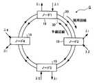
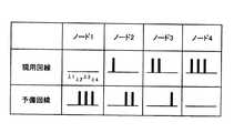
また、リング型の光ネットワークBの構成を基本に、光ファイバの断絶等のネットワーク故障時に備え、光ファイバを2本にしたリング型の光ネットワークも提案されている。図11は、2本の光ファイバを用いたリング型の光ネットワークの構成例を示す図である。また、図12は、図11に示したネットワーク構成における各ノードのWDM信号の多重状態を示した表である。リング型の光ネットワークCは、現用回線20と予備回線30と、4つの光分岐挿入ノード19(ノード1〜ノード4)から構成されている。図12に示したように現用回線20および予備回線30上のどの光分岐挿入ノード19(ノード1〜ノード4)にも同様のWDM信号が伝送されているため、現用回線20が断絶した場合にも、ノードにおける接続を瞬時に予備回線30へ切り替えるO−UPSR(Optical Unidirectional Path Switched Ring)によるプロテクションを行うことで、瞬時の通信復旧が可能である(例えば、下記特許文献2参照。)。 Further, based on the configuration of the ring-type optical network B, a ring-type optical network having two optical fibers has been proposed in the event of a network failure such as the disconnection of an optical fiber. FIG. 11 is a diagram illustrating a configuration example of a ring-type optical network using two optical fibers. FIG. 12 is a table showing the multiplexing state of WDM signals at each node in the network configuration shown in FIG. The ring-type optical network C includes an
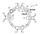
2本の光ファイバが同時に断絶した場合でも、瞬時の通信復旧が可能であるが、従来のネットワーク構成では新たな波長パスの設定ができなくなる。図13は、2本の光ファイバを用いたリング型の光ネットワークにおける現用回線および予備回線の光ファイバ同時断絶の例を示す図である。また、図14は、図13に示すネットワーク構成におけるノード1〜ノード4のWDM信号の多重状態を示した表である。 Even if two optical fibers are disconnected at the same time, instantaneous communication recovery is possible, but a new wavelength path cannot be set in the conventional network configuration. FIG. 13 is a diagram showing an example of simultaneous disconnection of optical fibers on a working line and a protection line in a ring-type optical network using two optical fibers. FIG. 14 is a table showing the multiplexing state of the WDM signals of
図13に示したようにノード1とノード4間の2本の光ファイバが同時に断絶した場合の現用回線20と予備回線30の各ノードにおけるWDM信号の多重状態について説明する。現用回線20では、光ファイバの断絶位置40の直後の光分岐挿入ノード19(ノード1)は、分岐を行う時点ではWDM信号が全く届かず、ノード1において特定波長λ1の光信号が挿入されたことで、ノード2では、分岐時点にλ1の光信号のみが多重されたWDM信号が伝送される。ノード1と同様にノード2においてλ2の光信号が、ノード3においてλ3の光信号が、ノード4においてλ4の光信号がそれぞれ挿入されることから断絶位置40の直後が最もWDM信号の多重された信号数が少なく、現用回線20の伝送方向に光分岐挿入ノード19を経由するにつれてWDM信号の多重された信号数が増し、断絶位置40の直前のノード4でWDM信号の多重信号数が最大になる。 A description will be given of the multiplexing state of the WDM signal in each node of the
また、予備回線30では、予備回線30の進行方向において断絶位置40の直後に位置するノード4にWDM信号が全く届かない状態となる。先に述べた現用回線20における各光分岐挿入ノード19のWDM信号の多重状態と同様にノード4→ノード3→ノード2→ノード1と、伝送方向の順に各光分岐挿入ノード19のWDM信号の多重信号数は増加していく。 Further, in the
以上述べたように、現用回線20においてノード4から挿入した光信号λ4をノード1へ伝送したい場合や、予備回線30においてノード1から挿入した光信号λ1をノード3へ伝送したい場合など、各回線の伝送方向からみて断絶位置40より先に位置する光分岐挿入ノードへは、光が到達できない。また、伝送回線として選択できるのは現用回線20と予備回線30のどちらか一方に限られ、光ファイバの断絶位置によって、現用回線か予備回線の選択で、伝送されるWDM信号の多重状態は変化してしまうことから、新たな波長パス設定を行うことができない。 As described above, when it is desired to transmit the optical signal λ4 inserted from the
2本の光ファイバが同時に断絶した状態で、新たな波長パス設定を行うためには、光ファイバの断絶位置を把握し、どの光分岐挿入ノード同士が通信可能であるかを見極めたうえで、各光分岐挿入ノードで定められている挿入用の光信号の波長の再設定を行う必要がある。そのためには、各光分岐挿入ノードに記録されている運用波長情報を更新しなければならない。運用波長情報の更新の方法としては、各光分岐挿入ノードに光スペクトルモニタを付加すればよいが、光スペクトルモニタは、一般的に高価である。よって、全ての光分岐挿入ノードに光スペクトルモニタを付加する方法はコスト面から考慮すると現実的ではない。 In order to set up a new wavelength path with two optical fibers disconnected at the same time, after grasping the optical fiber disconnection position and identifying which optical add / drop nodes can communicate with each other, It is necessary to reset the wavelength of the optical signal for insertion determined at each optical add / drop node. For this purpose, the operating wavelength information recorded in each optical add / drop node must be updated. As a method of updating the operating wavelength information, an optical spectrum monitor may be added to each optical add / drop node, but the optical spectrum monitor is generally expensive. Therefore, the method of adding an optical spectrum monitor to all the optical add / drop nodes is not practical from the viewpoint of cost.
本発明は、上記に鑑みてなされたものであって、2本の光ファイバが同時に断絶した場合でも新たな波長パス設定ができる低コストで簡単な構成のネットワーク管理装置、光分岐挿入ノードおよびネットワーク管理方法の提供を目的とする。 The present invention has been made in view of the above, and a low-cost and simple configuration network management apparatus, optical add / drop node, and network capable of setting a new wavelength path even when two optical fibers are disconnected at the same time The purpose is to provide a management method.
上述した課題を解決し、目的を達成するために、本発明のネットワーク管理装置は、現用回線と予備回線からなる2回線の光伝送路によって構成されたリング型の光ネットワーク上に備えられ光通信を行う複数の光分岐挿入ノードのうちの一つに接続されたネットワーク管理装置であって、前記光ネットワーク上における複数の光分岐挿入ノードの配置情報と、当該複数の光分岐挿入ノードが伝送している光信号の運用波長情報を保持する記憶手段と、前記複数の光分岐挿入ノードから通知された故障情報に基づいて前記記憶手段に保持された前記運用波長情報を更新し、当該更新を行った運用波長情報を前記複数の光分岐挿入ノードへ配布する制御手段と、を備えたことを特徴とする。 In order to solve the above-described problems and achieve the object, a network management apparatus according to the present invention is provided on a ring-type optical network constituted by two optical transmission lines composed of a working line and a protection line. A network management apparatus connected to one of a plurality of optical add / drop nodes that perform placement information on the optical add / drop nodes on the optical network, and the plurality of optical add / drop nodes transmit Updating the operating wavelength information held in the storage means based on the failure information notified from the plurality of optical add / drop nodes, and performing the update Control means for distributing the operating wavelength information to the plurality of optical add / drop nodes.
上記構成によれば、リング型の光ネットワークの現用回線および予備回線が同時断したときには、光ネットワーク上に配置された光分岐挿入ノードから通知された故障情報に基づいて運用波長情報を更新し、更新を行った運用波長情報が複数の光分岐挿入ノードへ配布される。これにより、光分岐挿入ノードごとに伝送中の特定波長と、伝送経路の再設定が可能となり、2本の光ファイバが断絶されたまま、新たな波長パスの設定が行えるようになる。 According to the above configuration, when the working line and the protection line of the ring optical network are simultaneously disconnected, the operating wavelength information is updated based on the failure information notified from the optical add / drop node arranged on the optical network, The updated operating wavelength information is distributed to a plurality of optical add / drop nodes. As a result, the specific wavelength being transmitted and the transmission path can be reset for each optical add / drop node, and a new wavelength path can be set while the two optical fibers are disconnected.
また、本発明の光分岐挿入ノードは、現用回線と予備回線からなる2回線に通信用信号とネットワーク監視用信号が伝送されているリング型の光ネットワーク上に備えられた光分岐挿入ノードにおいて、前記通信用信号のうち任意の波長の光信号を分岐して取り出し、特定波長の光信号を前記通信用信号として挿入する分岐挿入手段と、前記現用回線と予備回線の断絶をそれぞれ検出する断絶検出手段と、前記断絶検出手段によって検出された前記現用回線と予備回線の断絶に関する情報を前記ネットワーク監視用信号を介して前記光ネットワークを管理するネットワーク管理装置へ通知する通知手段と、を備えたことを特徴とする。 The optical add / drop node of the present invention is an optical add / drop node provided on a ring type optical network in which a communication signal and a network monitoring signal are transmitted to two lines consisting of a working line and a protection line. Branching and inserting means for branching and extracting an optical signal of an arbitrary wavelength from the communication signal and inserting an optical signal of a specific wavelength as the communication signal, and disconnection detection for detecting disconnection of the working line and the protection line, respectively. And a notification means for notifying the network management device that manages the optical network via the network monitoring signal of information relating to the disconnection of the working line and the protection line detected by the disconnection detecting means. It is characterized by.
上記構成によれば、現用回線と予備回線の断絶をそれぞれ検出し、断絶に関する情報をネットワーク監視用信号を介してネットワーク管理装置に通知する。これにより、ネットワーク管理装置では、光分岐挿入ノードからの通知に基づいて現用回線と予備回線が断絶した箇所を特定し、新たな波長パスの設定が行えるようになる。 According to the above configuration, the disconnection of the working line and the protection line is detected, respectively, and information about the disconnection is notified to the network management device via the network monitoring signal. As a result, the network management apparatus can specify a location where the working line and the protection line are disconnected based on the notification from the optical add / drop node and set a new wavelength path.
本発明によれば、リング型の光ネットワークにネットワーク管理装置を設け、各光分岐挿入ノードの運用波長情報を集中管理することで、低コストでシンプルな構成の光分岐挿入ノードであっても2本の光ファイバが同時に断絶するような事態に対応し、新たな波長パスの設定を可能にするという効果を奏する。 According to the present invention, a network management apparatus is provided in a ring-type optical network, and the operation wavelength information of each optical add / drop node is centrally managed. In response to the situation where the optical fibers of the book are cut off at the same time, it is possible to set a new wavelength path.
101,103 光分岐挿入ノード
401,700,704 光カプラ
402 波長可変フィルタ部
403 リジェクション・アドフィルタ
100 現用回線
110 予備回線
102 ネットワーク管理装置
404 WDMカプラ
405 光メディアコンバータ
406,703 電気ルータ
407,702 ノード制御部
701 光モニタDESCRIPTION OF SYMBOLS 101,103 Optical add / drop node 401,700,704
以下に、本発明にかかるネットワーク管理装置、光分岐挿入ノードおよびネットワーク管理方法の実施例を図面に基づいて詳細に説明する。なお、この実施例によりこの発明が限定されるものではない。 Embodiments of a network management device, an optical add / drop node, and a network management method according to the present invention will be described below in detail with reference to the drawings. Note that the present invention is not limited to the embodiments.
図1は、本発明にかかるリング型の光ネットワークの構成を示す図である。リング型の光ネットワークAは、相反する方向に光信号の伝送を行う現用回線100と、予備回線110からなる2本の光ファイバと、これら2本の光ファイバ上に備えられたOADM機能を有した4つの光分岐挿入ノード101と、NMS(Network Management System;ネットワーク管理システム)によるネットワーク管理装置102から構成される。ネットワーク管理装置102は、図示する例では、光分岐挿入ノード101のうちのノード1に接続されているように、4つの光分岐挿入ノード101のいずれか一つに接続されている。なお、図中の光分岐挿入ノード103に関しては実施例2に該当するため後で詳しく述べる。 FIG. 1 is a diagram showing a configuration of a ring-type optical network according to the present invention. The ring-type optical network A has two optical fibers composed of a working
現用回線100および予備回線110を伝送する光信号は、光分岐挿入ノード101間で光通信を行うためのWDM信号(通信用信号)と、リング型の光ネットワークAの各回線の状態を監視するためのOSC(Optical Supervisory Channel;光監視チャネル)による光信号(ネットワーク監視用信号)とがある。通常WDM信号は、1.5μm帯の波長の光を用い、OSCによる光信号は、1.3μm帯の波長の光を用いることから、これらの2つの信号は、相容れない独立した状態で、同一の回線上を伝送している。一般に、現用回線100の光ファイバが断絶した場合は、OSCを用いて各光分岐挿入ノードに故障情報(アラーム)を通知し、O−UPSRによる回線の復旧を行う。実施例1は、新たに設けたネットワーク管理装置102によって、OSCによる光信号(以下、「OSCリンク」という)の状態を集中管理する。 The optical signal transmitted through the working
図2は、ネットワーク管理装置のNMSの構成を示すブロック図である。また、図3は、ネットワーク管理装置に保持されている運用波長テーブルを示す表である。運用波長テーブルとは各光分岐挿入ノード101の運用波長情報を一括して、表にまとめたものである。ネットワーク管理装置102は、NMSを実現するため、信号入出力部201と、制御部202と、運用波長テーブル部(メモリ)203の3つの機能部から構成される。 FIG. 2 is a block diagram showing an NMS configuration of the network management apparatus. FIG. 3 is a table showing an operating wavelength table held in the network management apparatus. The operating wavelength table is a table in which the operating wavelength information of each optical add /
信号入出力部201は、光分岐挿入ノード101(ノード1)と直接接続され、相互に信号の伝送を行う。ネットワーク管理装置102には、OSCにより各光分岐挿入ノード101から信号入出力部201を通じて、運用波長情報が入力され、図3に示すような運用波長テーブルとして運用波長テーブル部203に保持されている、また運用波長テーブル部203には、接続されているリング型の光ネットワークAの光分岐挿入ノードの配置情報も保持されている。制御部202は、信号入出力部201から入力された、光分岐挿入ノード101からのアラームにより光ファイバの断絶を検出し、運用波長テーブル部203の光分岐挿入ノード101の配置情報から断絶位置を特定することで、運用波長テーブルの更新を行う。また、更新した運用波長テーブル部203の運用波長テーブルからの運用波長情報を、信号入出力部201を通じて、光分岐挿入ノード101へ伝送する機能を有する。 The signal input /
図3に示した運用波長テーブルは、各光分岐挿入ノード101(ノード1〜ノード4)における現用回線100と予備回線110を伝送する波長ごとの光信号の状態を表している。波長番号1〜4は、WDM信号の多重化されたλ1〜λ4の光信号を指す。各波長番号の運用情報は、通常1か0で示され、「1:運用中」、「0:非運用中」を表す。例えば、図3中の301で指し示した情報は、光分岐挿入ノード101(ノード1)における現用回線100を伝送するWDM信号中のλ4の光信号が、通信用として運用中であるか否かを表している。同様に302で指し示した情報は、光分岐挿入ノード101(ノード3)における予備回線110を伝送するWDM信号中のλ2の光信号が、通信用として運用中であるか否かを表している。基本的に現用回線100と予備回線110は同一のWDM信号を伝送しているため、通常時は、同一の光分岐挿入ノード101であれば、現用回線100と予備回線110の運用波長テーブルの情報は同一となる。 The operational wavelength table shown in FIG. 3 represents the state of the optical signal for each wavelength transmitted through the working
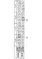
図4は、実施例1における光分岐挿入ノードの構成を示す図である。光分岐挿入ノード101は、光カプラ401と、波長可変フィルタ部402と、リジェクション・アドフィルタ403という従来の光分岐挿入ノードと同様の構成による光分岐挿入機能部400へ、ネットワーク管理装置102によって集中管理を行うための機能を付加した構成となっている。相反する方向に伝送を行う現用回線100と予備回線110が接続された光分岐挿入ノード101は、それぞれの回線の入力用ポートから入力された光信号を、WDMカプラ404によって、1.5μm帯のWDM信号と、1.3μm帯のOSCリンクに分離する。 FIG. 4 is a diagram illustrating a configuration of an optical add / drop node according to the first embodiment. The optical add /
分離されたWDM信号は、光分岐挿入機能部400へ入力され、光分岐挿入機能部400では、任意波長λiの光信号の分岐や特定波長λ1(ノード1の場合)の挿入を行うことで、光分岐挿入ノード101間の通信が行われる。一方、WDMカプラ404で分離されたOSCリンクは、光メディアコンバータ405で、光信号から電気信号へ変換され、電気ルータ406に入力される。電気ルータ406は、光分岐挿入ノード101内に備えられたノード制御部407に接続されており、このノード制御部407は、現用回線100および予備回線110から伝送されてきたOSCリンクの情報を現用回線100用、予備回線110用それぞれの光分岐挿入機能部400,400に反映させる機能を有する。 The separated WDM signal is input to the optical add /
さらに、図1に示したノード1に該当するようなネットワーク管理装置102と接続された光分岐挿入ノード101の場合、電気ルータ406から、ネットワーク管理装置102への接続が行われる。各光分岐挿入ノード101からのOSCリンクの情報は、現用回線100および予備回線110を経由し、ノード1へ伝送され、ノード1内の光メディアコンバータ405によって電気信号に変換された後、電気ルータ406から一括してネットワーク管理装置102へ伝送される。 Further, in the case of the optical add /
また、ネットワーク管理装置102からの各光分岐挿入ノード101への運用波長情報の更新などの制御情報は、電気信号としてノード1の電気ルータ406へ伝送された後、光メディアコンバータ405によって光信号に変換される。光信号となったネットワーク管理装置102からの情報は、OSCリンクとして、WDMカプラ408によって光分岐挿入機能部400から伝送されたWDM信号と合波され、現用回線100と予備回線110それぞれの出力用ポートからリング型の光ネットワークAに光信号を出力する。 Also, control information such as update of operating wavelength information to each optical add /
図5は、実施例1における光ファイバ断絶の検出から、運用波長の更新までの動作を示すフローチャートである。上述したような光分岐挿入ノード101(図4参照)およびネットワーク管理装置102(図2参照)からなるリング型の光ネットワークAにおいて、2本の光ファイバが同時に断絶した場合の新たな波長パスの設定までの動作を、図5を用いて説明する。 FIG. 5 is a flowchart illustrating the operation from the detection of the optical fiber disconnection to the update of the operating wavelength in the first embodiment. In the ring-type optical network A composed of the optical add / drop node 101 (see FIG. 4) and the network management apparatus 102 (see FIG. 2) as described above, a new wavelength path when two optical fibers are disconnected simultaneously. The operation up to the setting will be described with reference to FIG.
ネットワーク管理装置102には、常時、各光分岐挿入ノード101からOSCリンクが伝送されることでリング型の光ネットワークAの伝送状態の管理を行っている。よって、まずは制御部202(図2参照)において、複数の光分岐挿入ノード101からOSCリンクの断絶のアラームを取得したか否かの判断を行うこと(ステップS501)が、リング型の光ネットワークAの異常を検出する第1段階となる。複数の光分岐挿入ノード101からのアラームを取得していなければ(ステップS501:No)、2本の光ファイバが同時に断絶したものではないと判断し、待機状態となる。 The
なお、アラームを取得したものの一つの光分岐挿入ノード101からのOSCリンクの断絶のアラームであった場合は、片方の光ファイバの断絶という事態が想定される。現用回線100の断絶のアラームであれば、予備回線110を用いることで通信の復旧が行われる。ここでは2本の光ファイバが同時に断絶した場合の新たな波長パスの設定までの動作に関して述べる。 In the case where the alarm is acquired but the OSC link is disconnected from one optical add /
図5のフローチャートにもどり、ネットワーク管理装置102において、複数の光分岐挿入ノード101からのアラームを取得した場合(ステップS501:Yse)、取得した2つの光分岐挿入ノード101からのアラームが、同一のOSCリンクの断絶を通知しているか否かを判断する(ステップS502)。異なるOSCリンクの断絶の場合は(ステップS502:No)、ステップS501にもどり、待機状態となる。 Returning to the flowchart of FIG. 5, when the
2つの光分岐挿入ノード101からのアラームが、同一のOSCリンクの断絶を通知している場合(ステップS502:Yes)、アラームをOSCリンクに流した2つの光分岐挿入ノード101間を接続する2本の光ファイバが同時に断絶したとみなし、光ファイバの断絶位置を特定する(ステップS503)。つぎに、ネットワーク管理装置102に保持されている運用波長テーブル(図3参照)を参照し、ステップS503で特定した光ファイバの断絶位置の情報から運用波長テーブルを更新する(ステップS504)。ステップS504で更新された運用波長テーブルによる運用波長情報をOSCリンクによってリング型の光ネットワークA上の各光分岐挿入ノード101へ配布する(ステップS505)ことにより運用波長の更新動作は終了する。 When the alarms from the two optical add /
図6は、2本の光ファイバが同時に断絶した際の運用波長テーブルの例を示す表である。図示のように、光ファイバの断絶位置により運用波長テーブルの更新内容は異なる。例えば、図1におけるリング型の光ネットワークA上の光分岐挿入ノード101のうち、ノード1とノード2の間の2本の光ファイバが断絶した場合は、図6中の運用波長テーブル600のうちのノード1−2間断601に示すような更新内容となる。同様にノード2とノード3の間の2本の光ファイバが断絶した場合には、ノード2−3間断602、ノード3とノード4の間の2本の光ファイバが断絶した場合には、ノード3−4間断603、ノード4とノード1の間の2本の光ファイバが断絶した場合には、ノード4−1間断604にそれぞれ示すような運用波長テーブルへと更新される。図中の運用情報は、図3においても述べた「1:運用中」、「0:非運用中」に加え、「−:ファイバ断絶により運用不可」の3種類で示される。 FIG. 6 is a table showing an example of an operating wavelength table when two optical fibers are disconnected at the same time. As shown in the figure, the update contents of the operating wavelength table are different depending on the break position of the optical fiber. For example, when two optical fibers between the
以上述べたように実施例1では、光分岐挿入ノード101からのOSCリンクの情報をネットワーク管理装置102によって集中管理することで、光ファイバの断絶位置に応じて更新された運用波長テーブルによる運用波長情報が各光分岐挿入ノード101へ配布される。したがって、2本の光ファイバが断絶されたまま、各光分岐挿入ノード101ごとの特定波長と、伝送経路の再設定が可能となる。 As described above, in the first embodiment, the OSC link information from the optical add /
実施例2は、図1に示すリング型の光ネットワークAにおける4つの光分岐挿入ノード101を、WDM信号の入力パワーを監視する機構を備えた光分岐挿入ノード103(後述する図7参照)に置換し、現用回線100と、予備回線110と、ネットワーク管理装置102の構成や、ネットワーク管理装置102に保持されている通常時の運用波長テーブル(図3参照)も実施例1と全く同じであり、監視するWDM信号の変化によって光ファイバの断絶を検出し、運用波長テーブルの更新を行う。 In the second embodiment, the four optical add /
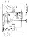
図7は、実施例2における光分岐挿入ノードの構成を示す図である。光分岐挿入ノード103は、光カプラ401と、波長可変フィルタ部402と、リジェクション・アドフィルタ403からなる光分岐挿入機能部400に、ネットワーク管理装置102によって集中管理を行うための機能を付加した構成となっている。 FIG. 7 is a diagram illustrating a configuration of an optical add / drop node according to the second embodiment. The optical add /
相反する方向に伝送を行う現用回線100と予備回線110が接続された光分岐挿入ノード103は、現用回線100、予備回線110それぞれの入力側のポートからλ1〜λ4の光信号が多重化されたWDM信号が入力される。実施例1と同様に、現用回線100と予備回線110を伝送するWDM信号は同一のものである。 In the optical add /
光分岐挿入ノード103に入力されたWDM信号は、まず光カプラ700によって2つに分岐される。この光カプラ700は、WDM信号の多重状態を反映させたまま2つに分ける働きを有する。光カプラ700によって分岐されたWDM信号の一方は、光分岐挿入機能部400へ入力され、任意波長λiの光信号の分岐や特定波長λ1(ノード1の場合)の挿入を行うことで、光分岐挿入ノード103間の通信が行われる。光カプラ700によって分岐されたWDM信号の他方は、PD(Photo Diode;受光素子)から構成された、光モニタ701へ入力される。PDは、入力された光を電気に変換する素子であり、入力されたWDM信号の光強度を監視することで光ファイバの断絶の検出を行う。 The WDM signal input to the optical add /
光モニタ701におけるWDM信号の監視情報は、ノード制御部702に伝送される。ノード制御部702は、光モニタ701からの監視情報を現用回線100用と、予備回線110用それぞれの光分岐挿入機能部400,400に反映させる機能を有しており、さらにネットワーク管理装置102へWDM信号の監視情報を伝送するために、電気ルータ703と接続される。電気ルータ703は、WDM信号の監視情報をネットワーク管理装置102へ伝送するとともに、ネットワーク管理装置102から運用波長情報の更新などの制御情報が伝送されてきた場合は光信号へ変換を行い、OSCリンクによって、他の光分岐挿入ノード(ノード2〜ノード4)へ制御情報を伝送させる。現用回線100へ伝送を行う場合は回線S1を経由し、予備回線110へ伝送を行う場合は、回線S2をそれぞれ経由し、光カプラ704によってWDM信号と合波され、各光分岐挿入ノード103へ伝送される。 The monitoring information of the WDM signal in the
図8は、実施例2における光ファイバ断絶の検出から、運用波長の更新までの動作を示すフローチャートである。上述したような光分岐挿入ノード103(図7参照)およびネットワーク管理装置102(図2参照)からなるリング型の光ネットワークAにおいて、2本の光ファイバが同時に断絶した場合の新たな波長パス設定までの動作を、図8を用いて説明する。 FIG. 8 is a flowchart illustrating the operation from the detection of the optical fiber disconnection to the update of the operating wavelength in the second embodiment. In the ring-type optical network A composed of the optical add / drop node 103 (see FIG. 7) and the network management apparatus 102 (see FIG. 2) as described above, a new wavelength path is set when two optical fibers are disconnected simultaneously. The operation up to here will be described with reference to FIG.
光モニタ701では、常時、WDM信号の光強度の監視が行われており、監視情報は、ノード制御部702に伝送されている。この光強度の大幅な低下、もしくは、WDM信号を検出できない状態は、光ファイバの断絶を示す要因となりうることから、光ファイバの断絶の検出を行うには、まずノード制御部702において、WDM信号の断絶が検出されたか否かの判断を行う(ステップS801)。WDM信号の断絶が検出されない場合(ステップS801:No)、WDM信号の伝送が通常どおりに行われているとみなし、待機状態となる。 The
WDM信号の断絶が検出された場合(ステップS801:Yes)、ネットワーク管理装置102が接続されている光分岐挿入ノード103(ノード1)の場合は、そのまま接続されている電気ルータ703を経由して、WDM信号の断絶のアラームをネットワーク管理装置102へ通知する。ネットワーク管理装置102が接続されていない光分岐挿入ノード103(ノード2〜ノード3)の場合は、接続されている電気ルータ703から、現用回線100もしくは予備回線110により、OSCを用いてノード1の電気ルータを経由させることで、WDM信号の断絶のアラームをネットワーク管理装置102へ通知する(ステップS802)。 When disconnection of the WDM signal is detected (step S801: Yes), in the case of the optical add / drop node 103 (node 1) to which the
WDM信号の断絶のアラームを通知されたネットワーク管理装置102は、制御部202(図2参照)によって、運用波長テーブル部203に保持されている運用波長テーブルを参照する(ステップS803)。これは、検出したWDM信号の断絶が光ファイバの断絶によるものなのか、該当する光分岐挿入ノード103において、運用中の波長がなかったためにWDM信号が検出されず断絶と検出されたのかを判断するためである。 The
ネットワーク管理装置102において、保持されている運用波長テーブルの該当する光分岐挿入ノード103に運用波長があるか否かの判断を行い(ステップS804)、運用波長がない場合(ステップS804:No)、光ファイバの断絶ではないと判断し、ステップS801にもどり待機状態となる。 In the
運用波長がある場合(ステップS804:Yes)、光ファイバの断絶が生じていると判断し、さらに複数の光分岐挿入ノード103からWDM信号の断絶のアラームを取得したか否かの判断を行う(ステップS805)。複数の光分岐挿入ノード103からのアラームを取得していなければ(ステップS805:No)、2本の光ファイバが同時に断絶したものではないと判断し、ステップS801にもどり、待機状態となる。 If there is an operating wavelength (step S804: Yes), it is determined that an optical fiber disconnection has occurred, and it is further determined whether or not a WDM signal disconnection alarm has been acquired from a plurality of optical add / drop nodes 103 ( Step S805). If alarms from a plurality of optical add /
複数の光分岐挿入ノード103からのアラームを取得した場合(ステップS805:Yes)、取得した2つの光分岐挿入ノード103からのアラームが、同一の光分岐挿入ノード103間のWDM信号の断絶を通知したか否かを判断する(ステップS806)。異なる光分岐挿入ノード103間のWDM信号の断絶を通知した場合は(ステップS806:No)、同一の光分岐挿入ノード103間のWDM信号の断絶を通知ではないと判断しステップS801にもどり、待機状態となる。 When alarms from a plurality of optical add /
2つの光分岐挿入ノード103からのアラームが、同一の光分岐挿入ノード103間のWDM信号の断絶を通知している場合(ステップS806:Yes)、アラームを通知した2つの光分岐挿入ノード103間を接続する2本の光ファイバが同時に断絶したとみなし、光ファイバの断絶位置を特定する(ステップS807)。つぎに、ネットワーク管理装置102に保持されている運用波長テーブル(図3参照)を参照し、ステップS807で特定した光ファイバの断絶位置の情報から運用波長テーブルを更新する(ステップS808)。ステップS808で更新された運用波長テーブルによる運用波長情報を、OSCを用いてリング型の光ネットワークA上の各光分岐挿入ノード103へ配布する(ステップS809)ことにより運用波長の更新動作は終了する。 When the alarm from the two optical add /
図8に示した更新動作によって各光分岐挿入ノード103へ配布される光ファイバの断絶位置ごとの運用波長情報は、実施例1と同様、図6に示したような運用波長テーブル600によるものとなる。 The operating wavelength information for each disconnection position of the optical fiber distributed to each optical add /
以上述べたように実施例2では、WDM信号を監視し、各光分岐挿入ノード103の監視情報をネットワーク管理装置102によって集中管理することで、光ファイバの断絶位置に応じて更新された運用波長情報が各光分岐挿入ノード103へ配布される。したがって、2本の光ファイバが断絶されたまま、光分岐挿入ノード103ごとの特定波長と、伝送経路の再設定が可能となる。 As described above, in the second embodiment, the WDM signal is monitored, and the monitoring information of each optical add /
以上のように、本発明にかかるネットワーク管理装置、光分岐挿入ノードおよびネットワーク管理方法は、メトロネットワークに有用であり、特に、高い信頼性が求められる企業内ネットワークに適している。
As described above, the network management device, the optical add / drop node, and the network management method according to the present invention are useful for metro networks, and are particularly suitable for corporate networks that require high reliability.
Claims (12)
Translated fromJapanese前記光ネットワーク上における複数の光分岐挿入ノードの配置情報と、当該複数の光分岐挿入ノードが伝送している光信号の運用波長情報を保持する記憶手段と、
前記複数の光分岐挿入ノードから通知された故障情報に基づいて前記記憶手段に保持された前記運用波長情報を更新し、当該更新を行った運用波長情報を前記複数の光分岐挿入ノードへ配布する制御手段と、
を備えたことを特徴とするネットワーク管理装置。A network management device provided on a ring-type optical network composed of two optical transmission lines composed of a working line and a protection line and connected to one of a plurality of optical add / drop nodes for optical communication. And
Storage means for holding arrangement information of a plurality of optical add / drop nodes on the optical network, and operating wavelength information of an optical signal transmitted by the plurality of optical add / drop nodes,
Based on the failure information notified from the plurality of optical add / drop nodes, the operating wavelength information held in the storage means is updated, and the updated operating wavelength information is distributed to the plurality of optical add / drop nodes. Control means;
A network management device comprising:
前記断絶判定手段における判定結果と、前記記憶手段に保持されている前記複数の光分岐挿入ノードの配置情報に基づいて、前記同時断の断絶位置を特定する断絶位置特定手段と、
を備えたことを特徴とする請求項1に記載のネットワーク管理装置。The control means includes disconnection determination means for determining whether the failure information notified from the plurality of optical add / drop nodes is simultaneous disconnection of both the working line and the protection line between the same nodes; ,
Based on the determination result in the disconnection determination means and the arrangement information of the plurality of optical add / drop nodes held in the storage means, the disconnection position specifying means for specifying the simultaneous disconnection position,
The network management apparatus according to claim 1, further comprising:
前記故障情報を通知した前記複数の光分岐挿入ノードについて、前記運用波長参照手段が参照した前記運用波長情報に基づいて、当該光分岐挿入ノードにおける光信号の伝送の有無を判断する運用波長判断手段と、
前記複数の光分岐挿入ノードから通知された前記故障情報が、同一のノード間における前記現用回線と予備回線がいずれも断絶された同時断であるかを判断する断絶判定手段と、
前記断絶判定手段における判定結果と、前記記憶手段に保持されている前記複数の光分岐挿入ノードの配置情報に基づいて、前記同時断の断絶位置を特定する断絶位置特定手段と、
を備えたことを特徴とする請求項1に記載のネットワーク管理装置。The control means refers to operating wavelength reference means for referring to the operating wavelength information related to the plurality of optical add / drop nodes that have notified the failure information from the storage means;
For the plurality of optical add / drop nodes that have notified the failure information, based on the operating wavelength information referred to by the operating wavelength reference means, an operating wavelength determining unit that determines whether or not an optical signal is transmitted in the optical add / drop node. When,
The failure information notified from the plurality of optical add / drop nodes is a disconnection determination means for determining whether the working line and the protection line are disconnected simultaneously between the same nodes,
Based on the determination result in the disconnection determination means and the arrangement information of the plurality of optical add / drop nodes held in the storage means, the disconnection position specifying means for specifying the simultaneous disconnection position,
The network management apparatus according to claim 1, further comprising:
前記通信用信号のうち任意の波長の光信号を分岐して取り出し、特定波長の光信号を前記通信用信号として挿入する分岐挿入手段と、
前記現用回線と予備回線の断絶をそれぞれ検出する断絶検出手段と、
前記断絶検出手段によって検出された前記現用回線と予備回線の断絶に関する情報を前記ネットワーク監視用信号を介して前記光ネットワークを管理するネットワーク管理装置へ通知する通知手段と、
を備えたことを特徴とする光分岐挿入ノード。In an optical add / drop node provided on a ring type optical network in which a communication signal and a network monitoring signal are transmitted to two lines consisting of a working line and a protection line,
Branching and inserting means for branching out an optical signal of an arbitrary wavelength from the communication signal and inserting an optical signal of a specific wavelength as the communication signal;
Disconnection detecting means for detecting disconnection of the working line and the protection line respectively;
Notifying means for notifying the network management device that manages the optical network via the network monitoring signal of information relating to the disconnection of the working line and the protection line detected by the disconnection detecting means;
An optical add / drop node comprising:
前記WDMカプラによって分離された前記ネットワーク監視用信号を前記ネットワーク管理装置へ伝送するネットワーク監視用信号伝送手段と、
を備えたことを特徴とする請求項6に記載の光分岐挿入ノード。The disconnection detecting means includes a WDM coupler that separates light input from the working line and the protection line into the communication signal and the network monitoring signal;
Network monitoring signal transmission means for transmitting the network monitoring signal separated by the WDM coupler to the network management device;
The optical add / drop node according to claim 6, further comprising:
前記ネットワーク上に配置された複数の光分岐挿入ノードから通知された故障情報を受信する受信工程と、
前記故障情報の受信に基づいて、前記光ネットワーク上における複数の光分岐挿入ノードの配置情報と、当該複数の光分岐挿入ノードが伝送している光信号の運用波長情報を更新する更新工程と、
更新を行った前記運用波長情報を前記複数の光分岐挿入ノードへ配布する配布工程と、
を含むことを特徴とするネットワーク管理方法。A network management method for managing a ring-type optical network composed of two optical transmission lines consisting of a working line and a protection line,
A receiving step of receiving failure information notified from a plurality of optical add / drop nodes arranged on the network;
Based on the reception of the failure information, an update step of updating the placement information of a plurality of optical add / drop nodes on the optical network and the operating wavelength information of the optical signals transmitted by the plurality of optical add / drop nodes;
A distribution step of distributing the updated operating wavelength information to the plurality of optical add / drop nodes;
A network management method comprising:
前記断絶判定工程における判定結果と、前記複数の光分岐挿入ノードの配置情報に基づいて、前記同時断の断絶位置を特定する断絶位置特定工程と、
を含むことを特徴とする請求項10に記載のネットワーク管理方法。Breakage determination step of determining whether the failure information notified from the plurality of optical add / drop nodes is simultaneous disconnection between the working line and the protection line between the same nodes,
Based on the determination result in the disconnection determination step and the arrangement information of the plurality of optical add / drop nodes, the disconnection position specifying step for specifying the simultaneous disconnection position,
The network management method according to claim 10, further comprising:
前記故障情報を通知した前記複数の光分岐挿入ノードについて、前記運用波長参照工程によって参照した前記運用波長情報に基づいて、当該光分岐挿入ノードにおける光信号の伝送の有無を判断する運用波長判断工程と、
前記複数の光分岐挿入ノードから通知された前記故障情報が、同一のノード間における前記現用回線と予備回線がいずれも断絶された同時断であるかを判断する断絶判定工程と、
前記断絶判定工程における判定結果と、前記複数の光分岐挿入ノードの配置情報に基づいて、前記同時断の断絶位置を特定する断絶位置特定工程と、
を含むことを特徴とする請求項10に記載のネットワーク管理方法。An operational wavelength reference step for referring to the operational wavelength information regarding the plurality of optical add / drop nodes that have notified the failure information;
An operation wavelength determining step for determining whether or not an optical signal is transmitted in the optical add / drop node based on the operating wavelength information referenced in the operating wavelength reference step for the plurality of optical add / drop nodes that have notified the failure information. When,
Breakage determination step of determining whether the failure information notified from the plurality of optical add / drop nodes is simultaneous disconnection between the working line and the protection line between the same nodes,
Based on the determination result in the disconnection determination step and the arrangement information of the plurality of optical add / drop nodes, the disconnection position specifying step for specifying the simultaneous disconnection position,
The network management method according to claim 10, further comprising:
Applications Claiming Priority (1)
| Application Number | Priority Date | Filing Date | Title |
|---|---|---|---|
| PCT/JP2005/000931WO2006080050A1 (en) | 2005-01-25 | 2005-01-25 | Network management device, light branching insert node, and network management method |
Publications (2)
| Publication Number | Publication Date |
|---|---|
| JPWO2006080050A1 JPWO2006080050A1 (en) | 2008-06-19 |
| JP4423326B2true JP4423326B2 (en) | 2010-03-03 |
Family
ID=36740085
Family Applications (1)
| Application Number | Title | Priority Date | Filing Date |
|---|---|---|---|
| JP2007500363AExpired - Fee RelatedJP4423326B2 (en) | 2005-01-25 | 2005-01-25 | Network management apparatus, optical add / drop node, and network management method |
Country Status (3)
| Country | Link |
|---|---|
| US (1) | US7643751B2 (en) |
| JP (1) | JP4423326B2 (en) |
| WO (1) | WO2006080050A1 (en) |
Families Citing this family (50)
| Publication number | Priority date | Publication date | Assignee | Title |
|---|---|---|---|---|
| US8873585B2 (en) | 2006-12-19 | 2014-10-28 | Corning Optical Communications Wireless Ltd | Distributed antenna system for MIMO technologies |
| JP4890239B2 (en)* | 2006-12-27 | 2012-03-07 | 富士通株式会社 | RPR transmission route designation method and apparatus |
| US8238749B2 (en) | 2007-08-27 | 2012-08-07 | Futurewei Technologies, Inc. | Distributing wavelength compatible with signaling protocols |
| EP2243258A1 (en)* | 2007-12-21 | 2010-10-27 | Telecom Italia S.p.A. | Protecting an ethernet network having a ring architecture |
| WO2010087308A1 (en)* | 2009-02-02 | 2010-08-05 | 日本電気株式会社 | Communication network management system, method, program, and management computer |
| CN102369678B (en) | 2009-02-03 | 2015-08-19 | 康宁光缆系统有限责任公司 | Optical fiber based distributed antenna systems, assemblies and related methods for calibrating optical fiber based distributed antenna systems, assemblies |
| US9673904B2 (en) | 2009-02-03 | 2017-06-06 | Corning Optical Communications LLC | Optical fiber-based distributed antenna systems, components, and related methods for calibration thereof |
| CN102396171B (en)* | 2009-02-03 | 2015-09-30 | 康宁光缆系统有限责任公司 | Based on the distributing antenna system of optical fiber, assembly and the correlation technique for monitoring and configure distributing antenna system based on optical fiber, assembly |
| US8305877B2 (en)* | 2009-09-10 | 2012-11-06 | Tyco Electronics Subsea Communications Llc | System and method for distributed fault sensing and recovery |
| US8280259B2 (en) | 2009-11-13 | 2012-10-02 | Corning Cable Systems Llc | Radio-over-fiber (RoF) system for protocol-independent wired and/or wireless communication |
| US8275265B2 (en) | 2010-02-15 | 2012-09-25 | Corning Cable Systems Llc | Dynamic cell bonding (DCB) for radio-over-fiber (RoF)-based networks and communication systems and related methods |
| EP2385642B1 (en) | 2010-05-07 | 2012-10-17 | ADVA AG Optical Networking | A method for providing protection in an optical communication network against connection failures |
| US9252874B2 (en) | 2010-10-13 | 2016-02-02 | Ccs Technology, Inc | Power management for remote antenna units in distributed antenna systems |
| WO2012148938A1 (en) | 2011-04-29 | 2012-11-01 | Corning Cable Systems Llc | Determining propagation delay of communications in distributed antenna systems, and related components, systems and methods |
| WO2012148940A1 (en) | 2011-04-29 | 2012-11-01 | Corning Cable Systems Llc | Systems, methods, and devices for increasing radio frequency (rf) power in distributed antenna systems |
| EP3010179A1 (en) | 2011-06-20 | 2016-04-20 | Plexxi Inc. | A method of processing a multicast frame in an optical network |
| US8682158B2 (en)* | 2011-08-24 | 2014-03-25 | Ciena Corporation | Systems and methods for detecting line flapping in optical networks |
| EP2832012A1 (en) | 2012-03-30 | 2015-02-04 | Corning Optical Communications LLC | Reducing location-dependent interference in distributed antenna systems operating in multiple-input, multiple-output (mimo) configuration, and related components, systems, and methods |
| WO2013162988A1 (en) | 2012-04-25 | 2013-10-31 | Corning Cable Systems Llc | Distributed antenna system architectures |
| MX340341B (en) | 2012-07-13 | 2016-07-05 | Huawei Tech Co Ltd | Wavelength negotiation method, system, and device for multi-wavelength passive optical network. |
| US20150222385A1 (en)* | 2012-07-26 | 2015-08-06 | Telefonaktiebolaget L M Ericsson (Publ) | Transponder for wdm ring network |
| WO2014024192A1 (en) | 2012-08-07 | 2014-02-13 | Corning Mobile Access Ltd. | Distribution of time-division multiplexed (tdm) management services in a distributed antenna system, and related components, systems, and methods |
| US9455784B2 (en) | 2012-10-31 | 2016-09-27 | Corning Optical Communications Wireless Ltd | Deployable wireless infrastructures and methods of deploying wireless infrastructures |
| CN105308876B (en) | 2012-11-29 | 2018-06-22 | 康宁光电通信有限责任公司 | Remote unit antennas in distributing antenna system combines |
| US9647758B2 (en) | 2012-11-30 | 2017-05-09 | Corning Optical Communications Wireless Ltd | Cabling connectivity monitoring and verification |
| US9130691B2 (en)* | 2013-02-25 | 2015-09-08 | Verizon Patent And Licensing Inc. | Optical burst switched network nodes |
| CN104104431B (en) | 2013-04-11 | 2018-12-28 | 上海中兴软件有限责任公司 | The method, apparatus and system that ROADM optical-fiber network is monitored |
| CN105452951B (en) | 2013-06-12 | 2018-10-19 | 康宁光电通信无线公司 | Voltage type optical directional coupler |
| WO2014199380A1 (en) | 2013-06-12 | 2014-12-18 | Corning Optical Communications Wireless, Ltd. | Time-division duplexing (tdd) in distributed communications systems, including distributed antenna systems (dass) |
| WO2015008512A1 (en)* | 2013-07-16 | 2015-01-22 | 日本電気株式会社 | Transmission device, transmission system, and path-switching method |
| US9247543B2 (en) | 2013-07-23 | 2016-01-26 | Corning Optical Communications Wireless Ltd | Monitoring non-supported wireless spectrum within coverage areas of distributed antenna systems (DASs) |
| US9661781B2 (en) | 2013-07-31 | 2017-05-23 | Corning Optical Communications Wireless Ltd | Remote units for distributed communication systems and related installation methods and apparatuses |
| US9385810B2 (en) | 2013-09-30 | 2016-07-05 | Corning Optical Communications Wireless Ltd | Connection mapping in distributed communication systems |
| JP6258683B2 (en)* | 2013-12-03 | 2018-01-10 | 株式会社日立製作所 | Optical transmission system |
| US9178635B2 (en) | 2014-01-03 | 2015-11-03 | Corning Optical Communications Wireless Ltd | Separation of communication signal sub-bands in distributed antenna systems (DASs) to reduce interference |
| US9775123B2 (en) | 2014-03-28 | 2017-09-26 | Corning Optical Communications Wireless Ltd. | Individualized gain control of uplink paths in remote units in a distributed antenna system (DAS) based on individual remote unit contribution to combined uplink power |
| US9357551B2 (en) | 2014-05-30 | 2016-05-31 | Corning Optical Communications Wireless Ltd | Systems and methods for simultaneous sampling of serial digital data streams from multiple analog-to-digital converters (ADCS), including in distributed antenna systems |
| US9525472B2 (en) | 2014-07-30 | 2016-12-20 | Corning Incorporated | Reducing location-dependent destructive interference in distributed antenna systems (DASS) operating in multiple-input, multiple-output (MIMO) configuration, and related components, systems, and methods |
| US9730228B2 (en) | 2014-08-29 | 2017-08-08 | Corning Optical Communications Wireless Ltd | Individualized gain control of remote uplink band paths in a remote unit in a distributed antenna system (DAS), based on combined uplink power level in the remote unit |
| US9602210B2 (en) | 2014-09-24 | 2017-03-21 | Corning Optical Communications Wireless Ltd | Flexible head-end chassis supporting automatic identification and interconnection of radio interface modules and optical interface modules in an optical fiber-based distributed antenna system (DAS) |
| US9420542B2 (en) | 2014-09-25 | 2016-08-16 | Corning Optical Communications Wireless Ltd | System-wide uplink band gain control in a distributed antenna system (DAS), based on per band gain control of remote uplink paths in remote units |
| US9729267B2 (en) | 2014-12-11 | 2017-08-08 | Corning Optical Communications Wireless Ltd | Multiplexing two separate optical links with the same wavelength using asymmetric combining and splitting |
| US20160249365A1 (en) | 2015-02-19 | 2016-08-25 | Corning Optical Communications Wireless Ltd. | Offsetting unwanted downlink interference signals in an uplink path in a distributed antenna system (das) |
| US9681313B2 (en) | 2015-04-15 | 2017-06-13 | Corning Optical Communications Wireless Ltd | Optimizing remote antenna unit performance using an alternative data channel |
| US9948349B2 (en) | 2015-07-17 | 2018-04-17 | Corning Optical Communications Wireless Ltd | IOT automation and data collection system |
| US10560214B2 (en) | 2015-09-28 | 2020-02-11 | Corning Optical Communications LLC | Downlink and uplink communication path switching in a time-division duplex (TDD) distributed antenna system (DAS) |
| EP3364568B1 (en)* | 2015-11-26 | 2020-04-15 | Nippon Telegraph and Telephone Corporation | Communication system and connector |
| US10236924B2 (en) | 2016-03-31 | 2019-03-19 | Corning Optical Communications Wireless Ltd | Reducing out-of-channel noise in a wireless distribution system (WDS) |
| CN106303768B (en)* | 2016-08-31 | 2019-10-18 | 武汉光迅科技股份有限公司 | The photosynthetic wave separater module for having automatic discovery feature |
| US10771269B2 (en)* | 2018-03-09 | 2020-09-08 | Cisco Technology, Inc. | Automated intelligent node for hybrid fiber-coaxial (HFC) networks |
Family Cites Families (5)
| Publication number | Priority date | Publication date | Assignee | Title |
|---|---|---|---|---|
| JP3753866B2 (en)* | 1998-07-01 | 2006-03-08 | 株式会社日立製作所 | Self-relieving optical network |
| JP2001156821A (en) | 1999-11-30 | 2001-06-08 | Toshiba Corp | Wavelength multiplexing ring network system, node device thereof, and failure recovery method |
| JP4064032B2 (en)* | 2000-02-01 | 2008-03-19 | 株式会社東芝 | Communications system |
| JP3526445B2 (en)* | 2001-02-23 | 2004-05-17 | 株式会社東芝 | WDM ring network system, optical path setting method, failure recovery method, and program |
| JP2004235741A (en)* | 2003-01-28 | 2004-08-19 | Fujitsu Ltd | Optical transmission device and optical wavelength multiplexing network having the optical transmission device |
- 2005
- 2005-01-25JPJP2007500363Apatent/JP4423326B2/ennot_activeExpired - Fee Related
- 2005-01-25WOPCT/JP2005/000931patent/WO2006080050A1/ennot_activeCeased
- 2007
- 2007-07-19USUS11/826,889patent/US7643751B2/ennot_activeExpired - Fee Related
Also Published As
| Publication number | Publication date |
|---|---|
| WO2006080050A1 (en) | 2006-08-03 |
| US20070264011A1 (en) | 2007-11-15 |
| JPWO2006080050A1 (en) | 2008-06-19 |
| US7643751B2 (en) | 2010-01-05 |
Similar Documents
| Publication | Publication Date | Title |
|---|---|---|
| JP4423326B2 (en) | Network management apparatus, optical add / drop node, and network management method | |
| US5870212A (en) | Self-healing optical network | |
| US7852752B2 (en) | Method and apparatus for designing backup communication path, and computer product | |
| JP4562443B2 (en) | Optical transmission system and optical transmission method | |
| EP2385642B1 (en) | A method for providing protection in an optical communication network against connection failures | |
| EP1496634A2 (en) | Self-healing wavelength division multiplexing passive optical network system | |
| JPH09163413A (en) | Optical communication network device, optical transmission system and optical communication network | |
| JPH11252016A (en) | Node for optical communication and wavelength division multiplex optical transmission equipment having ring configuration composed of the same | |
| JP5527716B2 (en) | Wavelength path demultiplexing optical transmission equipment | |
| JP5371593B2 (en) | Optical cross-connect device | |
| US7715715B2 (en) | Shared optical ring protection in a multi-fiber ring | |
| US20040151498A1 (en) | Optical communication system | |
| JP3475756B2 (en) | Communication network, communication network / node device, and failure recovery method | |
| JP5065832B2 (en) | Optical transmission system and operating device | |
| JP4859909B2 (en) | Transparent optical network and transparent optical network fault monitoring method | |
| JP2003046456A (en) | Optical transmission network system and fault monitoring method for optical transmission network system | |
| JP4488813B2 (en) | Method and system for managing directly connected optical elements | |
| JP2012005088A (en) | Network management apparatus and optical path designing method | |
| JP3788263B2 (en) | Communication network, communication network node device, and failure recovery method | |
| JP3683791B2 (en) | Optical network system | |
| JP3764342B2 (en) | Optical monitoring switching device, optical transmission device, optical communication system, and optical communication path switching method | |
| JP2004254339A (en) | Communication network and communication network node device | |
| JP2003143171A (en) | Transmission communication system, transmission device, and communication path bypass method | |
| JP3312707B2 (en) | Optical fiber communication network | |
| JP2005117603A (en) | Optical communication system |
Legal Events
| Date | Code | Title | Description |
|---|---|---|---|
| TRDD | Decision of grant or rejection written | ||
| A01 | Written decision to grant a patent or to grant a registration (utility model) | Free format text:JAPANESE INTERMEDIATE CODE: A01 Effective date:20091201 | |
| A01 | Written decision to grant a patent or to grant a registration (utility model) | Free format text:JAPANESE INTERMEDIATE CODE: A01 | |
| A61 | First payment of annual fees (during grant procedure) | Free format text:JAPANESE INTERMEDIATE CODE: A61 Effective date:20091207 | |
| FPAY | Renewal fee payment (event date is renewal date of database) | Free format text:PAYMENT UNTIL: 20121211 Year of fee payment:3 | |
| R150 | Certificate of patent or registration of utility model | Ref document number:4423326 Country of ref document:JP Free format text:JAPANESE INTERMEDIATE CODE: R150 Free format text:JAPANESE INTERMEDIATE CODE: R150 | |
| FPAY | Renewal fee payment (event date is renewal date of database) | Free format text:PAYMENT UNTIL: 20121211 Year of fee payment:3 | |
| FPAY | Renewal fee payment (event date is renewal date of database) | Free format text:PAYMENT UNTIL: 20131211 Year of fee payment:4 | |
| LAPS | Cancellation because of no payment of annual fees |