JP4421940B2 - Moving picture coding apparatus and method, and moving picture decoding apparatus and method - Google Patents
Moving picture coding apparatus and method, and moving picture decoding apparatus and methodDownload PDFInfo
- Publication number
- JP4421940B2 JP4421940B2JP2004144074AJP2004144074AJP4421940B2JP 4421940 B2JP4421940 B2JP 4421940B2JP 2004144074 AJP2004144074 AJP 2004144074AJP 2004144074 AJP2004144074 AJP 2004144074AJP 4421940 B2JP4421940 B2JP 4421940B2
- Authority
- JP
- Japan
- Prior art keywords
- image
- moving image
- stereo
- unit
- decoding
- Prior art date
- Legal status (The legal status is an assumption and is not a legal conclusion. Google has not performed a legal analysis and makes no representation as to the accuracy of the status listed.)
- Expired - Fee Related
Links
Images


Classifications
- H—ELECTRICITY
- H04—ELECTRIC COMMUNICATION TECHNIQUE
- H04N—PICTORIAL COMMUNICATION, e.g. TELEVISION
- H04N19/00—Methods or arrangements for coding, decoding, compressing or decompressing digital video signals
- H04N19/50—Methods or arrangements for coding, decoding, compressing or decompressing digital video signals using predictive coding
- H04N19/597—Methods or arrangements for coding, decoding, compressing or decompressing digital video signals using predictive coding specially adapted for multi-view video sequence encoding
- H—ELECTRICITY
- H04—ELECTRIC COMMUNICATION TECHNIQUE
- H04N—PICTORIAL COMMUNICATION, e.g. TELEVISION
- H04N13/00—Stereoscopic video systems; Multi-view video systems; Details thereof
- H04N13/10—Processing, recording or transmission of stereoscopic or multi-view image signals
- H04N13/106—Processing image signals
- H04N13/161—Encoding, multiplexing or demultiplexing different image signal components
- H—ELECTRICITY
- H04—ELECTRIC COMMUNICATION TECHNIQUE
- H04N—PICTORIAL COMMUNICATION, e.g. TELEVISION
- H04N13/00—Stereoscopic video systems; Multi-view video systems; Details thereof
- H04N13/10—Processing, recording or transmission of stereoscopic or multi-view image signals
- H04N13/106—Processing image signals
- H04N13/172—Processing image signals image signals comprising non-image signal components, e.g. headers or format information
- H04N13/178—Metadata, e.g. disparity information
- H—ELECTRICITY
- H04—ELECTRIC COMMUNICATION TECHNIQUE
- H04N—PICTORIAL COMMUNICATION, e.g. TELEVISION
- H04N13/00—Stereoscopic video systems; Multi-view video systems; Details thereof
- H04N13/10—Processing, recording or transmission of stereoscopic or multi-view image signals
- H04N13/194—Transmission of image signals
- H—ELECTRICITY
- H04—ELECTRIC COMMUNICATION TECHNIQUE
- H04N—PICTORIAL COMMUNICATION, e.g. TELEVISION
- H04N2213/00—Details of stereoscopic systems
- H04N2213/007—Aspects relating to detection of stereoscopic image format, e.g. for adaptation to the display format
Landscapes
- Engineering & Computer Science (AREA)
- Multimedia (AREA)
- Signal Processing (AREA)
- Library & Information Science (AREA)
- Compression Or Coding Systems Of Tv Signals (AREA)
- Testing, Inspecting, Measuring Of Stereoscopic Televisions And Televisions (AREA)
Description
Translated fromJapanese本発明は、いわゆる右目画像(右眼用画像ともいう)と、いわゆる左目画像(左眼用画像ともいう)を縦1列ごとに交互に並べた動画像(いわゆるステレオ動画像)、および奇数行画像と偶数行画像を横1行ごとに交互に並べた動画像(いわゆるインターレース動画像)を符号化する動画像符号化装置および方法、並びに、上記ステレオ動画像およびインターレース動画像を復号化する動画像復号化装置および方法に関する。 The present invention relates to a so-called right-eye image (also referred to as a right-eye image) and a so-called left-eye image (also referred to as a left-eye image) alternately arranged in vertical columns (so-called stereo moving images), and odd rows Moving image encoding apparatus and method for encoding moving images (so-called interlaced moving images) in which images and even-numbered row images are arranged alternately every horizontal row, and moving images for decoding the stereo moving images and interlaced moving images The present invention relates to an image decoding apparatus and method.
なお、「左フィールド画像」とは、右目画像と左目画像とを縦1列ごとに交互に並べられたステレオ動画像において、左目画像のみを抽出して得られる画像を意味し、「右フィールド画像」とは、上記のステレオ動画像において、右目画像のみを抽出して得られる画像を意味する。 The “left field image” means an image obtained by extracting only the left eye image in a stereo moving image in which the right eye image and the left eye image are alternately arranged in a vertical column. "Means an image obtained by extracting only the right-eye image from the stereo moving image.
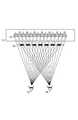
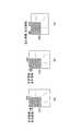
立体動画像表示装置の一つとして、図1に示すような多数の画像配列から成るフィルター10を具備した液晶ディスプレイ11の前面に、多数の孔が開設されたスリット板12を配置した構成のパララックスバリア方式の立体映像表示装置が知られている。この立体映像表示装置は、視聴者の左目13からはフィルター上の左目画像Lのみが見え、視聴者の右目14からはフィルター上の右目画像Rのみが見えるように構成されているため、視聴者は立体動画像を視認することができる。なお、図1のスリット板12に代えて、レンチキュラー板を配置した構成の立体映像表示装置も知られている。 As one of the stereoscopic moving image display devices, a parallax having a configuration in which a
また、他の立体動画像符号化方式としては、例えば下記の特許文献1に開示された「立体映像伝送方法及び装置」が知られている。この技術では、図2(a)に示す縦1列ごとに交互に左目画像と右目画像が配置された立体画像に対し、まず図2(b)に示すように画像の左半分に左目画像を、右半分に右目画像を集めて再配置することで変換画像を作成する。次に、作成された変換画像に対し、動画像符号化、符号化データの送信、符号化データの受信、動画像復号化といった処理が行われる。その後、復号化された変換画像の画素配置を、再度、縦1列ごとに交互に左目画像と右目画像を配置し直して、入力信号である立体画像と同じ画像を再現する。
立体画像では、近くの物体は左目画像と右目画像との視差が大きいが、遠くの物体は左目画像と右目画像との視差はほとんどない。そのため、特に遠くの物体を示すブロックにおいて、左目画像と右目画像との相関性を利用することにより、データ圧縮効率を向上させることができる。 In a stereoscopic image, a nearby object has a large parallax between the left eye image and the right eye image, but a distant object has little parallax between the left eye image and the right eye image. Therefore, data compression efficiency can be improved by utilizing the correlation between the left-eye image and the right-eye image, particularly in a block indicating a distant object.
ところが、上記の従来技術では、変換画像において、左半分に左目画像を、右半分に右目画像を配置しているため、動画像符号化を行う場合、左目画像と右目画像との相関性を利用できず、データ圧縮効率を向上させることができない、という課題がある。 However, in the above prior art, in the converted image, the left eye image is arranged in the left half and the right eye image is arranged in the right half. Therefore, when performing video coding, the correlation between the left eye image and the right eye image is used. There is a problem that data compression efficiency cannot be improved.
また、変換画像において、一度、左半分に左目画像を、右半分に右目画像を配置して符号化するため、前述したパララックスバリア方式の立体動画像表示装置で表示する場合には、復号化処理後の画像の画素配置を変更することで、再度、左目画像と右目画像とを縦1列ごとに交互に配置し直す必要がある。このため、処理の効率化が困難であるという課題がある。 In addition, in the converted image, the left eye image is arranged once in the left half and the right eye image is arranged in the right half and encoded. Therefore, when the converted image is displayed on the above-described parallax barrier stereoscopic moving image display device, decoding is performed. By changing the pixel arrangement of the processed image, it is necessary to again arrange the left-eye image and the right-eye image alternately for each vertical column. For this reason, there exists a subject that the efficiency of a process is difficult.
本発明は、上記課題を解決するために成されたものであり、立体動画像に対する画像処理を効率良く行うことができる動画像符号化装置および方法、並びに動画像復号化装置および方法を提供することを目的とする。 The present invention has been made to solve the above-described problems, and provides a moving image encoding apparatus and method, and a moving image decoding apparatus and method capable of efficiently performing image processing on a stereoscopic moving image. For the purpose.
上記目的を達成するために、本発明の動画像符号化装置は、右目画像と左目画像を縦1列ごとに交互に並べたステレオ動画像、および奇数行画像と偶数行画像を横1行ごとに交互に並べたインターレース動画像を符号化する動画像符号化装置であって、符号化対象の動画像がステレオ動画像であるか否かを判定する動画像種別判定部と、符号化対象の動画像がステレオ動画像であると判定された場合に、当該動画像における縦方向が横方向に変わるように、当該動画像を所定方向に所定角度回転させる動画像回転部と、ステレオ動画像でないと判定された動画像、およびステレオ動画像であると判定され前記所定角度回転した動画像をインターレース符号化する動画像インターレース符号化部と、符号化対象の動画像がステレオ動画像であるか否かを示す情報、並びに、前記動画像回転部によって符号化対象の動画像に対し行われた回転の方向および角度に関する情報を含むステレオ画像識別子を符号化するステレオ画像識別子符号化部と、前記動画像インターレース符号化部によるインターレース符号化で得られた符号化ビットストリームと、前記ステレオ画像識別子符号化部による符号化で得られたステレオ画像識別子の符号とを多重化することで多重化符号化ビットストリームを作成する多重化部とを備えることを特徴とする。
In order to achieve the above object, the moving image encoding apparatus of the present invention includes a stereo moving image in which a right eye image and a left eye image are alternately arranged in a vertical column, and an odd row image and an even row image in each horizontal row. A moving image encoding apparatus that encodes interlaced moving images arranged alternately, a moving image type determining unit that determines whether or not a moving image to be encoded is a stereo moving image, and an encoding target When it is determined that the moving image is a stereo moving image, a moving image rotating unit that rotates the moving image by a predetermined angle in a predetermined direction so that the vertical direction of the moving image changes to a horizontal direction, and a non-stereo moving image A moving image interlace encoding unit that interlace-codes the moving image determined to be a stereo moving image and the moving image that has been rotated by the predetermined angle, and the encoding target moving image is a stereo moving imageInformation indicatingwhether, and, and the stereo picture identifier encoding section for encoding a stereoscopic picture identifiercontaining information on direction and angle of rotation performed to the moving picture to be coded by the moving picture rotation section, wherein Multiplexing coding is performed by multiplexing a coded bit stream obtained by interlace coding by a moving image interlace coding unit and a stereo image identifier code obtained by coding by the stereo image identifier coding unit. And a multiplexing unit that creates a bitstream.
なお、上記の動画像種別判定部は、入力された画像信号に基づいて、符号化対象の動画像がステレオ動画像であるか否かを判定してもよいし、予め定めた規則に従って符号化対象の動画像がステレオ動画像であるか否かを判定してもよい。 The moving image type determination unit may determine whether the moving image to be encoded is a stereo moving image based on the input image signal, or may perform encoding according to a predetermined rule. It may be determined whether or not the target moving image is a stereo moving image.
また、上記の動画像回転部は、符号化対象の動画像がステレオ動画像であると判定された場合に、当該動画像における縦方向が横方向に変わるように、例えば、当該動画像を右に+90°回転させてもよいし、当該動画像を右に−90°回転させてもよい。 In addition, when the moving image to be encoded is determined to be a stereo moving image, the moving image rotating unit described above, for example, moves the moving image to the right so that the vertical direction in the moving image changes to the horizontal direction. May be rotated + 90 °, or the moving image may be rotated −90 ° to the right.
また、上記目的を達成するために、本発明の動画像復号化装置は、右目画像と左目画像を縦1列ごとに交互に並べたステレオ動画像、および奇数行画像と偶数行画像を横1行ごとに交互に並べたインターレース動画像を復号化する動画像復号化装置であって、受信された多重化符号化ビットストリームを、動画像の符号化ビットストリームとステレオ画像識別子の符号とに分離する分離部と、分離された前記動画像の符号化ビットストリームをインターレース復号化する動画像インターレース復号化部と、分離された前記ステレオ画像識別子の符号を復号化するステレオ画像識別子復号化部と、前記ステレオ画像識別子復号化部による復号化で得られたステレオ画像識別子に含まれる前記動画像がステレオ動画像であるか否かを示す情報に基づき、前記動画像がステレオ動画像である場合、前記復号化で得られたステレオ画像識別子に含まれる符号化時に前記動画像に対し行われた回転の方向および角度に関する情報に基づいて、前記回転の方向とは逆方向に前記角度だけ前記動画像を回転させる画像処理を、前記動画像インターレース復号化部によるインターレース復号化で得られた動画像信号に対し行う処理制御部とを備えることを特徴とする。
In order to achieve the above object, the moving picture decoding apparatus according to the present invention includes a stereo moving picture in which a right-eye picture and a left-eye picture are alternately arranged in a vertical column, and an odd-numbered picture and an even-numbered picture in a horizontal direction. A moving picture decoding apparatus for decoding interlaced moving pictures arranged alternately for each row, and separating a received multiplexed coded bit stream into a coded bit stream of a moving picture and a code of a stereo picture identifier A demultiplexing unit, a moving image interlace decoding unit that interlace-decodes the encoded bitstream of the separated moving image, a stereo image identifier decoding unit that decodes a code of the separated stereo image identifier,based on information indicating whether the moving image contained in the stereoscopic picture identifier obtained by the decoding by the stereoscopic picture identifier decoding unitis a stereo moving picture When the moving image is a stereo moving image, the rotation is performed based on information on the direction and angle of rotation performed on the moving image at the time of encoding included in the stereo image identifier obtained by the decoding. A processing control unit that performsimage processing for rotating the moving image by the angle in a direction opposite to the direction of the moving image signal obtained by interlace decoding by the moving image interlace decoding unit. And
上記の動画像符号化装置および動画像復号化装置によれば、符号化対象の動画像がステレオ動画像であると判定された場合に、当該動画像における縦方向が横方向に変わるように、当該動画像を所定方向に所定角度回転させ、ステレオ動画像でないと判定された動画像、およびステレオ動画像であると判定され前記所定角度回転した動画像をインターレース符号化することで、左目画像と右目画像の相関性を利用して、データ圧縮の効率を向上させることができる。 According to the moving image encoding device and the moving image decoding device, when it is determined that the moving image to be encoded is a stereo moving image, the vertical direction in the moving image is changed to the horizontal direction. The moving image is rotated by a predetermined angle in a predetermined direction, and the moving image determined not to be a stereo moving image and the moving image determined to be a stereo moving image and rotated by the predetermined angle are interlace-encoded to obtain a left-eye image Data compression efficiency can be improved by utilizing the correlation of the right-eye image.
また、入力したステレオ動画像信号と同じ画素配置の出力画像が得られるため、パララックスバリア方式の立体動画像表示装置で表示する場合に、復号化処理後の画像信号のラインの順番を変更し直すことなく、入力画像と同じ画像信号を得ることができる。 In addition, since an output image having the same pixel arrangement as the input stereo moving image signal is obtained, the order of the lines of the image signal after decoding processing is changed when displaying on a parallax barrier type stereoscopic moving image display device. The same image signal as the input image can be obtained without correction.
さらに、縦1列ごとに交互に左目画像と右目画像が配置されたステレオ動画像信号、および横1行ごとに交互に奇数行画像と偶数行画像が配置されたインターレース動画像信号を、同一の動画像符号化装置、および動画像復号化装置でそれぞれ符号化、復号化を行うことができ、装置の有効利用が可能である。 Furthermore, a stereo moving image signal in which left-eye images and right-eye images are alternately arranged every vertical column, and an interlaced moving image signal in which odd-numbered row images and even-numbered row images are alternately arranged every horizontal row are identical to each other. Encoding and decoding can be performed by the moving image encoding device and the moving image decoding device, respectively, and the device can be used effectively.
以上のような動画像符号化装置および動画像復号化装置に係る発明は、以下のような動画像符号化方法および動画像復号化方法に係る発明として捉えることができ、同様の効果を得ることができる。 The invention relating to the moving image encoding device and the moving image decoding device as described above can be regarded as the invention relating to the following moving image encoding method and moving image decoding method, and obtain the same effect. Can do.
即ち、本発明に係る動画像符号化方法は、右目画像と左目画像を縦1列ごとに交互に並べたステレオ動画像、および奇数行画像と偶数行画像を横1行ごとに交互に並べたインターレース動画像を符号化する動画像符号化方法であって、符号化対象の動画像がステレオ動画像であるか否かを判定する動画像種別判定ステップと、符号化対象の動画像がステレオ動画像であると判定された場合に、当該動画像における縦方向が横方向に変わるように、当該動画像を所定方向に所定角度回転させる動画像回転ステップと、ステレオ動画像でないと判定された動画像、およびステレオ動画像であると判定され前記所定角度回転した動画像をインターレース符号化する動画像インターレース符号化ステップと、符号化対象の動画像がステレオ動画像であるか否かを示す情報、並びに、前記動画像回転ステップによって符号化対象の動画像に対し行われた回転の方向および角度に関する情報を含むステレオ画像識別子を符号化するステレオ画像識別子符号化ステップと、前記インターレース符号化で得られた符号化ビットストリームと、前記符号化で得られたステレオ画像識別子の符号とを多重化することで多重化符号化ビットストリームを作成する多重化ステップとを有することを特徴とする。
That is, in the moving image encoding method according to the present invention, the stereo moving image in which the right eye image and the left eye image are alternately arranged in every vertical column, and the odd row image and the even row image are alternately arranged in every horizontal row. A moving image encoding method for encoding an interlaced moving image, the moving image type determining step for determining whether or not the moving image to be encoded is a stereo moving image, and the moving image to be encoded is a stereo moving image. A moving image rotation step for rotating the moving image by a predetermined angle in a predetermined direction so that the vertical direction of the moving image changes to a horizontal direction when the image is determined to be an image, and a moving image determined not to be a stereo moving image A video interlace encoding step for interlace encoding the video that has been determined to be an image and a stereo video and rotated by the predetermined angle, and the video to be encoded is a stereo videoInformation indicatingwhether, and, and the stereo picture identifier encoding step for encoding a stereo image identifiercontaining information on direction and angle of rotation performed to the moving picture to be coded by the moving picture rotation step, A multiplexing step of creating a multiplexed encoded bit stream by multiplexing the encoded bit stream obtained by the interlaced encoding and the stereo image identifier code obtained by the encoding. Features.
また、本発明に係る動画像復号化方法は、右目画像と左目画像を縦1列ごとに交互に並べたステレオ動画像、および奇数行画像と偶数行画像を横1行ごとに交互に並べたインターレース動画像を復号化する動画像復号化方法であって、受信された多重化符号化ビットストリームを、動画像の符号化ビットストリームとステレオ画像識別子の符号とに分離する分離ステップと、分離された前記動画像の符号化ビットストリームをインターレース復号化する動画像インターレース復号化ステップと、分離された前記ステレオ画像識別子の符号を復号化するステレオ画像識別子復号化ステップと、前記復号化で得られたステレオ画像識別子に含まれる前記動画像がステレオ動画像であるか否かを示す情報に基づき、前記動画像がステレオ動画像である場合、前記復号化で得られたステレオ画像識別子に含まれる符号化時に前記動画像に対し行われた回転の方向および角度に関する情報に基づいて、前記回転の方向とは逆方向に前記角度だけ前記動画像を回転させる画像処理を、前記インターレース復号化で得られた動画像信号に対し行う処理制御ステップとを有することを特徴とする。
In addition, the moving picture decoding method according to the present invention includes a stereo moving picture in which the right eye image and the left eye picture are alternately arranged in the vertical column, and an odd line image and the even line image in the horizontal line alternately. A video decoding method for decoding interlaced video, wherein the received multiplexed encoded bitstream is separated into a video encoded bitstream and a stereo image identifier code. A moving image interlace decoding step for interlace decoding the encoded bit stream of the moving image, a stereo image identifier decoding step for decoding the code of the separated stereo image identifier, and the decodingIt based the moving image contained in the stereoscopic picture identifieris the information indicating whether a stereoscopic moving picture, the moving image is a stereoscopic moving picture der In this case, based on the information about the direction and angle of the rotation performed on the moving image at the time of encoding included in the stereo image identifier obtained by the decoding, the angle in the direction opposite to the rotation direction is the angle. And a processing control step of performingimage processing for rotating the moving image on the moving image signal obtained by the interlace decoding.
本発明によれば、左目画像と右目画像の相関性を利用して、データ圧縮の効率を向上させることができる。 According to the present invention, the efficiency of data compression can be improved by utilizing the correlation between the left eye image and the right eye image.
また、入力したステレオ動画像信号と同じ画素配置の出力画像が得られるため、パララックスバリア方式の立体動画像表示装置で表示する場合に、復号化処理後の画像信号のラインの順番を変更し直すことなく、入力画像と同じ画像信号を得ることができる。 In addition, since an output image having the same pixel arrangement as the input stereo moving image signal is obtained, the order of the lines of the image signal after decoding processing is changed when displaying on a parallax barrier type stereoscopic moving image display device. The same image signal as the input image can be obtained without correction.
さらに、縦1列ごとに交互に左目画像と右目画像が配置されたステレオ動画像信号、および横1行ごとに交互に奇数行画像と偶数行画像が配置されたインターレース動画像信号を、同一の動画像符号化装置、および動画像復号化装置でそれぞれ符号化、復号化を行うことができ、装置の有効利用が可能である。 Furthermore, a stereo moving image signal in which left-eye images and right-eye images are alternately arranged every vertical column, and an interlaced moving image signal in which odd-numbered row images and even-numbered row images are alternately arranged every horizontal row are identical to each other. Encoding and decoding can be performed by the moving image encoding device and the moving image decoding device, respectively, and the device can be used effectively.
以下、図面を参照しながら、本発明の実施形態に係る動画像符号化装置および方法、並びに動画像復号化装置および方法を説明する。なお、各図において、同一要素には同一符号を付して重複する説明を省略する。 Hereinafter, a moving picture coding apparatus and method, and a moving picture decoding apparatus and method according to embodiments of the present invention will be described with reference to the drawings. In addition, in each figure, the same code | symbol is attached | subjected to the same element and the overlapping description is abbreviate | omitted.
[第1実施形態]
(動画像符号化装置の構成)
まず、図3を用いて、本実施形態に係る動画像符号化装置を説明する。本実施形態に係る動画像符号化装置30は、その機能的な構成要素として、動画像種別判定部301と、スイッチ302と、動画像回転部303と、スイッチ304と、動画像インターレース符号化部305と、ステレオ画像識別子符号化部306と、多重化部307とを備えて構成される。[First embodiment]
(Configuration of video encoding device)
First, the moving picture coding apparatus according to the present embodiment will be described with reference to FIG. The moving
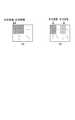
動画像種別判定部301は、入力された動画像信号308を受信し、受信した動画像の種別を判定する。受信した動画像が、図4(a)のように縦1列ごとに交互に左目画像と右目画像とが配置されたステレオ画像信号であった場合、動画像種別判定部301は、入力画像がステレオ画像であるという情報(例えば「1」にセットしたステレオ画像識別子)310をスイッチ302と、スイッチ304と、ステレオ画像識別子符号化部306とへ送る。一方、受信した動画像が、図4(b)のように横1行ごとに交互に奇数行画像と偶数行画像とが配置されたインターレース画像信号であった場合、動画像種別判定部301は、入力画像がステレオ画像でないという情報(例えば「0」にセットしたステレオ画像識別子)310をスイッチ302と、スイッチ304と、ステレオ画像識別子符号化部306とへ送る。また、動画像種別判定部301は、受信した動画像信号309をスイッチ302に送る。なお、上記の図4は、入力画像が横352画素、縦288画素であった場合の例を示す。 The moving image
動画像種別判定部301での画像種別の判定は、例えば、入力画像に付加された画像種別に関する情報を検出し、検出した情報に基づいて行うことができる。また、動画像種別判定部301での画像種別の判定は、符号化前に外部から与えられた設定ファイル等の画像種別に関する情報に基づいて行っても良い。 The determination of the image type in the moving image
また、動画像種別判定部301での画像種別の判定は、以下のように、入力された画像の輝度値の関係を解析した結果を基に行っても良い。例えば、入力された画像を縦1列ごとに交互に分離して左フィールド画像と右フィールド画像を作成し、それらの分離した各フィールド画像の横方向の輝度値の相関が、分離前のフレーム画像の横方向の輝度値の相関に比べて高い場合、入力された画像をステレオ画像と判定しても良い。また、例えば、入力された画像を横1列ごとに交互に分離して上フィールド画像と下フィールド画像を作成し、それらの分離した各フィールド画像の縦方向の輝度値の相関が、分離前のフレーム画像の縦方向の輝度値の相関に比べて高い場合、入力された画像をインターレース画像と判定しても良い。 Further, the determination of the image type in the moving image
なお、画像種別の判定法は、上記例示した方法に限定されるものではない。 Note that the image type determination method is not limited to the method exemplified above.
スイッチ302は、動画像種別判定部301から送られた動画像信号309と、ステレオ画像識別子310を受信し、ステレオ画像識別子が1の場合は、動画像信号309を動画像回転部303に送り、ステレオ画像識別子が0の場合は、動画像信号309をスイッチ304に送る。 The
動画像回転部303は、スイッチ302から送られた動画像信号309を受信し、動画像信号309により表される動画像を右に+90°回転して、インターレース動画像と同様に横1行ごとに交互に右目画像と左目画像が配置された動画像を表す動画像信号311に変換し、動画像信号311をスイッチ304に送る。 The moving
図5は、動画像回転部303によってステレオ動画像を右に+90°回転した例を示し、このうち図5(a)はスイッチ302から送られた動画像信号309により表される動画像を示し、図5(b)は図5(a)の動画像を右に+90°回転した動画像を示す。なお、上記の図5は、入力画像が横352画素、縦288画素であった場合の例を示す。 FIG. 5 shows an example in which the stereo moving image is rotated to the right by + 90 ° by the moving
スイッチ304は動画像種別判定部301から送られたステレオ画像識別子310を基に、動画像回転部303から送られた動画像信号311、およびスイッチ302から送られた動画像信号309のうち一方を選択する。即ち、スイッチ304は、ステレオ画像識別子310が1の場合、動画像回転部303から送られた動画像信号311を、ステレオ画像識別子310が0の場合、スイッチ302から送られた動画像信号309を、それぞれ選択し、選択した動画像信号を動画像信号312として動画像インターレース符号化部305に送る。 The
動画像インターレース符号化部305は、スイッチ304から送られた動画像信号312を受けて動画像のインターレース符号化を行うことで符号化ビットストリーム313を作成する。そして、動画像インターレース符号化部305は、作成された符号化ビットストリーム313を多重化部307へ送る。なお、動画像インターレース符号化部305で使用するインターレース符号化方式の一例としては、H.264/AVC符号化方式(Joint Video Team (JVT) of ISO/IEC MPEG and ITU-VCEG, “Editor’s Proposed Draft Text Modifications for Joint Video Specification (ITU-T Rec.H.264|ISO/IEC 14496-10 AVC), Geneva modifications draft 37”を参照)が挙げられる。但し、上記のH.264/AVC符号化方式に限らず、インターレース画像の符号化に対応するあらゆる方式の符号化法を適用することができる。 The moving image
ステレオ画像識別子符号化部306は、動画像種別判定部301から送られたステレオ画像識別子310を符号化し、符号化で得られた符号314を多重化部307へ送る。 The stereo image
多重化部307は、動画像インターレース符号化部305から送られた符号化ビットストリーム313と、ステレオ画像識別子符号化部306から送られたステレオ画像識別子の符号314とを多重化し、多重化で得られたビットストリームを多重化符号化ビットストリーム315として外部へ伝送する。 The
図6〜図9は、外部へ伝送する多重化符号化ビットストリーム315の例を示したものである。 6 to 9 show examples of the multiplexed encoded
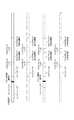
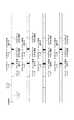
多重化符号化ビットストリーム315は、各シーケンスの先頭を表す同期信号の後に、動画像全体に関する符号化情報(シーケンスヘッダ)、動画像の各フレームに関する符号化情報(フレームヘッダ)、動画像の符号化単位であるマクロブロックを何個か合わせた各スライスに関する符号化情報(スライスヘッダ)、動画像の各マクロブロックに関する符号化情報(マクロブロックヘッダ)、およびマクロブロックごとの符号化情報が多重化されて構成される。 The multiplexed encoded
入力された動画像の種別に関する情報であるステレオ画像識別子の符号は、図6のようにシーケンスヘッダに含んで伝送しても良いし、図7のようにフレームヘッダに含んで伝送しても良い。また、上記ステレオ画像識別子の符号は、図8のようにスライスヘッダに含んで伝送しても良いし、図9のようにマクロブロックヘッダに含んで伝送しても良い。 The stereo image identifier code, which is information related to the type of the input moving image, may be transmitted by being included in the sequence header as shown in FIG. 6, or may be transmitted by being included in the frame header as shown in FIG. . The stereo image identifier code may be transmitted by being included in a slice header as shown in FIG. 8, or may be transmitted by being included in a macroblock header as shown in FIG.
なお、動画像回転部303は、スイッチ302から送られた動画像信号309を受信し、図5(a)に示す動画像信号309により表される動画像を右に−90°回転(即ち、左に+90°回転)して、インターレース動画像と同様に横1行ごとに交互に左目画像と右目画像が配置された動画像(図5(c)参照)を表す動画像信号311に変換し、動画像信号311をスイッチ304に送っても良い。 The moving
動画像回転部303が、スイッチ302から送られた動画像信号309を、右に+90°回転するか、−90°回転するかは、予め決定された回転方法に従う。 Whether the moving
また、動画像回転部303が動画像信号309を、右に+90°回転するか、−90°回転するかを示す情報は、動画像の符号化に関する情報として、ステレオ画像識別子とともに多重化符号化ビットストリーム315で送信しても良い。例えば、ステレオ画像識別子が1で、動画像回転部303がスイッチ302から送られた動画像信号309を右に+90°回転して動画像信号311に変換する場合は符号「10」を、ステレオ画像識別子が1で、動画像回転部303がスイッチ302から送られた動画像信号309を右に−90°回転して動画像信号311に変換する場合は符号「11」を、ステレオ画像識別子が0の場合は符号「0」を、それぞれ動画像の符号化に関する情報として、ステレオ画像識別子とともに多重化部307で多重化して、多重化符号化ビットストリーム315として伝送しても良い。 Information indicating whether the moving
(動画像符号化装置の動作)
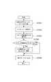
次に、図10を用いて、本発明における動画像符号化装置30の動作を説明する。(Operation of video encoding device)
Next, the operation of the moving
まず、動画像種別判定部301が、入力された動画像の画像種別判定として、当該動画像がステレオ画像であるか否かを判定する(ステップS1001)。ここで、入力された動画像がステレオ画像であった場合、動画像種別判定部301はステレオ画像識別子を「1」とし(ステップS1002)、動画像回転部303は予め決定された回転方法に従って、入力された動画像を右に+90°または−90°回転させる(ステップS1004)。一方、入力された動画像がステレオ画像でなかった場合、動画像種別判定部301はステレオ画像識別子を「0」とする(ステップS1003)。 First, the moving image
前述したように、スイッチ304は、ステレオ画像識別子310が1の場合、動画像回転部303から送られた動画像信号311を、ステレオ画像識別子310が0の場合、スイッチ302から送られた動画像信号309を、それぞれ選択し、選択した動画像信号を動画像信号312として動画像インターレース符号化部305に送る。 As described above, the
動画像信号312を受信した動画像インターレース符号化部305は、動画像のインターレース符号化を行い(ステップS1005)、符号化ビットストリーム313を作成する。また、ステレオ画像識別子符号化部306は、ステレオ画像識別子の符号化を行い(ステップS1006)、符号化情報314を作成する。 The moving image
最後に、多重化部307は、符号化ビットストリーム313と符号化情報314とを多重化して多重化符号化ビットストリーム315を作成し(ステップS1007)、図10の処理を終了する。 Finally, the
(動画像復号化装置の構成)
次に、図11を用いて、本発明に係る動画像復号化装置を説明する。本発明に係る動画像復号化装置110は、その機能的な構成要素として、分離部1101と、動画像インターレース復号化部1102と、ステレオ画像識別子復号化部1103と、スイッチ1104と、動画像逆回転部1105と、スイッチ1106とを備えて構成される。(Configuration of video decoding device)
Next, the moving picture decoding apparatus according to the present invention will be described with reference to FIG. The moving
分離部1101は、入力された多重化符号化ビットストリーム315を、動画像の符号化ビットストリーム1107とステレオ画像識別子の符号1108とに分離し、符号化ビットストリーム1107を動画像インターレース復号化部1102に、ステレオ画像識別子の符号1108をステレオ画像識別子復号化部1103に、それぞれ送る。 The
動画像インターレース復号化部1102は、分離部1101から送られた動画像の符号化ビットストリームに対し復号化を行うことで動画像信号1109を得る。そして、動画像インターレース復号化部1102は、復号化で得られた動画像信号1109をスイッチ1104に送る。なお、動画像インターレース復号化部1102で使用するインターレース復号化方式の一例としては、H.264/AVC復号化方式が挙げられる。但し、H.264/AVC復号化方式に限らず、インターレース画像の復号化に対応するあらゆる方式の復号化法を適用することができる。 The moving image
ステレオ画像識別子復号化部1103は、分離部1101から送られたステレオ画像識別子の符号1108に対し復号化を行い、復号化されたステレオ画像識別子1110をスイッチ1104およびスイッチ1106に送る。 Stereo image
スイッチ1104は、動画像インターレース復号化部1102から送られた動画像信号1109と、ステレオ画像識別子復号化部1103から送られたステレオ画像識別子1110とを受信し、ステレオ画像識別子が1の場合は、動画像信号1109を動画像逆回転部1105に送り、ステレオ画像識別子が0の場合は、動画像信号1109をスイッチ1106に送る。 The
動画像逆回転部1105は、スイッチ1104から送られた動画像信号1109を受信し、図12(a)に示す動画像信号1109で表される動画像を左に+90°回転することで、図12(c)に示す縦1列ごとに交互に右目画像と左目画像とが配置された動画像信号1110に変換し、動画像信号1110をスイッチ1106に送る。この動画像逆回転部1105は、特許請求の範囲に記載した「処理制御部」に対応する。なお、上記の図12は、入力画像が横352画素、縦288画素であった場合の例を示す。 The moving image
スイッチ1106は、ステレオ画像識別子復号化部1103から送られたステレオ画像識別子1110を基に、動画像逆回転部1105から送られた動画像信号1111およびスイッチ1104から送られた動画像信号1109のうち一方を選択する。即ち、スイッチ1106は、ステレオ画像識別子1110が1の場合、動画像逆回転部1105から送られた動画像信号1111を、ステレオ画像識別子1110が0の場合、スイッチ1104から送られた動画像信号1109を、それぞれ選択し、選択した動画像信号を動画像信号1112として所定のタイミングで表示デバイス(図示せず)へ出力し、入力映像信号を再生する。 Based on the
なお、動画像逆回転部1105は、スイッチ1104から送られた動画像信号1109を受信し、図12(b)に示す動画像信号1109により表される動画像を左に−90°回転することで、図12(c)に示す縦1列ごとに交互に左目画像と右目画像とが配置された動画像信号1110に変換し、動画像信号1110をスイッチ1106に送っても良い。 The moving image
動画像逆回転部1105が、スイッチ1104から送られた動画像信号1109を受信し、動画像信号1109により表される動画像を左に+90°回転するか−90°回転するかは、予め決定された回転方法に従う。 The moving image
また、動画像逆回転部1105が動画像信号1109を、左に+90°回転するか−90°回転するかの処理は、動画像の符号化に関する情報として、ステレオ画像識別子とともに多重化符号化ビットストリーム315に含まれた符号に基づいて行っても良い。例えば、以下のような処理を行ってもよい。多重化符号化ビットストリーム315の動画像の符号化に関する符号が「10」の場合は、ステレオ画像識別子を1とし、動画像逆回転部1105がスイッチ1104から送られた動画像信号1109を左に+90°回転する。上記符号が「11」の場合は、ステレオ画像識別子を1とし、動画像逆回転部1105がスイッチ1104から送られた動画像信号1109を左に−90°回転する。上記符号が「0」の場合は、ステレオ画像識別子を0とする。 In addition, the process of whether the moving image
(動画像復号化装置の動作)
次に、図13を用いて、本発明における動画像復号化装置110の動作を説明する。(Operation of video decoding device)
Next, the operation of the moving
まず、分離部1101が、入力された多重化符号化ビットストリームを受信し、動画像の符号化ビットストリーム1107とステレオ画像識別子の符号1108とに分離する(ステップS1301)。 First, the
次に、動画像インターレース復号化部1102が、動画像の符号化ビットストリーム1107を復号化することで動画像信号1109を復元する(ステップS1302)。次に、ステレオ画像識別子復号化部1103が、ステレオ画像識別子の符号1108を復号化することでステレオ画像識別子1110を復元する(ステップS1303)。 Next, the moving image
次に、ステレオ画像識別子が1であるか否かを判定し(ステップS1304)、ステレオ画像識別子が1であった場合、動画像逆回転部1105が上記復元された動画像信号1109を左に+90°または−90°回転する(ステップS1305)。一方、ステレオ画像識別子が1でなかった場合は、ステップS1305の回転処理をスキップして、後述のステップS1306へ進む。 Next, it is determined whether or not the stereo image identifier is 1 (step S1304). If the stereo image identifier is 1, the moving image
最後に、スイッチ1106は、ステレオ画像識別子が1の場合、動画像逆回転部1105から送られた動画像信号1111を、ステレオ画像識別子1110が0の場合、スイッチ1104から送られた動画像信号1109を、それぞれ選択し、選択された動画像信号を動画像信号1112として所定のタイミングで表示デバイス(図示せず)へ出力する(ステップS1306)。 Finally, the
以上述べた第1実施形態によれば、縦1列ごとに交互に左目画像と右目画像とが配置されたステレオ動画像信号を+90°または−90°回転してインターレース画像と同様の画素配置にした後、インターレース符号化することで、左目画像と右目画像との相関性を利用して、データ圧縮の効率を向上させることができる。 According to the first embodiment described above, the stereo moving image signal in which the left-eye image and the right-eye image are alternately arranged every vertical column is rotated by + 90 ° or −90 ° to obtain the same pixel arrangement as that of the interlaced image. After that, by performing interlace encoding, it is possible to improve the efficiency of data compression by utilizing the correlation between the left-eye image and the right-eye image.
また、動画像回転部303でステレオ画像を+90°または−90°回転させてインターレース画像と同様の画素配置にしてインターレース符号化し、動画像逆回転部1105で復号画像を+90°または−90°逆回転させてステレオ画像に復元することで、パララックスバリア方式の立体動画像表示装置で表示する場合に、復号化処理後の画像信号のラインの順番を変更し直すことなく、入力画像と同じ画像信号を得ることができる。 Further, the moving
さらに、縦1列ごとに交互に左目画像と右目画像が配置されたステレオ動画像信号、および横1行ごとに交互に奇数行画像と偶数行画像が配置されたインターレース動画像信号に対し、同一の動画像符号化装置で符号化を行うことができるとともに、同一の動画像復号化装置で復号化を行うことができ、装置の有効利用が可能である。 Furthermore, it is the same for a stereo moving image signal in which left-eye images and right-eye images are alternately arranged for each vertical column, and an interlaced moving image signal in which odd-numbered row images and even-numbered row images are alternately arranged for each horizontal row. Can be encoded by the same moving picture encoding apparatus, and can be decoded by the same moving picture decoding apparatus, so that the apparatus can be used effectively.
なお、動画像回転部303および動画像逆回転部1105は、動画像信号309および動画像信号1109を、それぞれフレーム単位で右に+90°または−90°回転、および左に+90°または−90°回転しても良い。 The moving
また、動画像回転部303および動画像逆回転部1105は、動画像信号309および動画像信号1109を、それぞれスライス単位で右に+90°または−90°回転、および左に+90°または−90°回転しても良い。 The moving
また、動画像回転部303および動画像逆回転部1105は、動画像信号309および動画像信号1109を、それぞれマクロブロック単位で右に+90°または−90°回転、および左に+90°または−90°回転しても良い。 The moving
上記では、右に+90°または−90°回転、および左に+90°または−90°回転という例を示したが、回転角度はこれらに限定されるものではなく、動画像における縦方向が横方向に変わるように回転させればよい。例えば、右に+270°または−270°回転、および左に+270°または−270°回転という回転パターンを採用してもよい。 In the above, an example of + 90 ° or −90 ° rotation to the right and + 90 ° or −90 ° rotation to the left is shown, but the rotation angle is not limited to these, and the vertical direction in the moving image is the horizontal direction Rotate to change to For example, a rotation pattern of + 270 ° or −270 ° rotation to the right and + 270 ° or −270 ° rotation to the left may be employed.
また、上記では、動画像信号を、動画像回転部303により所定方向に回転させ、動画像逆回転部1105により当該所定方向とは逆方向に回転させる(即ち、逆回転させる)例を示したが、これに限定されるものではなく、動画像逆回転部1105により当該所定方向と同じ方向に回転させることで、元の動画像信号を復元してもよい。例えば、動画像信号を、動画像回転部303により右に+90°回転させ、動画像逆回転部1105により右に+270°回転させることで、元の動画像信号を復元してもよい。 In the above description, an example in which a moving image signal is rotated in a predetermined direction by the moving
[第2実施形態]
(動画像符号化装置の構成)
まず、図14を用いて、本発明に係る動画像符号化装置140について説明する。以下に説明する動画像符号化装置140は、H.264/AVC符号化方式に準拠した符号化装置である。[Second Embodiment]
(Configuration of video encoding device)
First, the moving
ここで、動画像符号化装置140に入力される動画像信号としての入力映像信号は、右目画像と左目画像とを縦1列ごとに交互に並べたステレオ動画像、または奇数行画像と偶数行画像とを横1行ごとに交互に並べたインターレース動画像を表す動画像信号である。本実施形態では、入力された動画像信号により表される画像は、16画素×16ライン固定の正方矩形領域であるマクロブロックに分割され、マクロブロック単位で以下の符号化処理が行われる。 Here, an input video signal as a moving image signal input to the moving
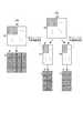
動画像符号化装置140は、図14に示すように、機能的な構成要素として、動画像種別判定部1401と、ステレオ/インターレース動き検出部1402と、ステレオ/インターレース動き補償部1403と、フレームメモリ1404と、ステレオ/インターレース空間予測部1405と、スイッチ1406と、減算器1407と、ステレオ/インターレース直交変換部1408と、量子化部1409と、可変長符号化部1410と、逆量子化部1411と、ステレオ/インターレース逆直交変換部1412と、加算器1413とを備えて構成される。以下、各構成要素について説明する。 As shown in FIG. 14, the moving
動画像種別判定部1401は、符号化対象の動画像を表す外部から入力された動画像信号としての入力映像信号1421を受信した後、入力映像信号1421により表される画像(以下「入力画像」という)をマクロブロックに分割し、マクロブロック単位で減算器1407およびステレオ/インターレース動き検出部1402に対し、それぞれ入力画像信号1422、1423を送る。また、動画像種別判定部1401は、入力画像がステレオ画像であるか否かを判定し、ステレオ画像である場合、画像の種別に関する情報であるステレオ画像識別子を「1」とし、ステレオ画像でない場合、上記ステレオ画像識別子を「0」とする。そして、動画像種別判定部1401は、動画像全体での符号化に関する情報(シーケンス情報)、各フレーム画像単位での符号化に関する情報(フレーム情報)、1個以上のマクロブロックをまとめた各スライス単位での符号化に関する情報(スライス情報)、および各マクロブロック単位での符号化に関する情報(マクロブロック情報)とともに、上記ステレオ画像識別子の情報を信号1440としてステレオ/インターレース動き検出部1402と可変長符号化部1410へ送る。なお、上記ステレオ画像識別子の符号は、図6のようにシーケンスヘッダに含んで伝送しても良いし、図7のようにフレームヘッダに含んで伝送しても良い。また、上記ステレオ画像識別子の符号は、図8のようにスライスヘッダに含んで伝送しても良いし、図9のようにマクロブロックヘッダに含んで伝送しても良い。 The moving image
フレームメモリ1404は、過去に符号化済みのフレーム画像信号を記憶しておく部分である。 The
ステレオ/インターレース動き検出部1402は、動画像種別判定部1401から送られた画像の種別に関する情報、シーケンス情報、フレーム情報、スライス情報、およびマクロブロック情報を合わせた信号1440を基に、予測モードの選択と動きベクトルの検出を行う部分である。H.264/AVC符号化方式では、マクロブロックごとに、予測モードとして、入力された映像信号と時間的に異なる複数の符号化済みフレーム画像信号を参照して予測を行う複数のフレーム間予測モードと、同一空間上の符号化済みである近傍の画素値を用いて空間予測を行う複数のフレーム内予測モードとが用意されている。具体的には、動き検出部1402は、予測モードとしてフレーム間予測モードを選択した場合、参照画像信号1424および隣接ブロックの動きベクトル1442を用いて、予めフレームメモリ1404に蓄積されている複数の符号化済み画像の中から所定の探索範囲内で、符号化対象領域の画像信号パターンに類似する画像信号パターンを探し出す。そして、符号化対象領域の画像信号パターンと、当該類似する画像信号パターンとの間の空間的な変位量である動きベクトルを検出する。 The stereo / interlace
より詳細には、ステレオ/インターレース動き検出部1402は、入力画像がステレオ画像である場合(即ち、ステレオ画像識別子が「1」にセットされている場合)に、入力画像をフレーム画像(図15(a)参照)としてフレーム間予測した場合(即ち、フレーム画像でのフレーム間予測を行った場合)と、入力画像を左フィールド画像(図15(b)参照)と右フィールド画像(図15(c)参照)とに分離してフレーム間予測した場合(即ち、フィールド画像でのフレーム間予測を行った場合)との符号化効率を比較し、符号化効率の高い方のフレーム間予測を選択する。 More specifically, when the input image is a stereo image (that is, when the stereo image identifier is set to “1”), the stereo / interlace
また、ステレオ/インターレース動き検出部1402は、入力画像がインターレース画像である場合(即ち、ステレオ画像識別子が「0」にセットされている場合)に、入力画像をフレーム画像(図16(a)参照)としてフレーム間予測した場合(即ち、フレーム画像でのフレーム間予測を行った場合)と、入力画像を奇数行画像(上フィールド画像:図16(b)参照)と偶数行画像(下フィールド画像:図16(c)参照)とに分離してフレーム間予測した場合(即ち、フィールド画像でのフレーム間予測を行った場合)との符号化効率を比較し、符号化効率の高い方のフレーム間予測を選択する。 The stereo / interlace
ステレオ/インターレース動き検出部1402は、検出された動きベクトルと、符号化済みの隣接ブロックの動きベクトル1442から算出される最適予測動きベクトル(動きベクトル予測値)との差分情報である動きベクトル差分値と、動きベクトルの検出に用いた参照フレーム画像信号を示す参照フレーム番号と、選択された予測モードとを含む信号1425を可変長符号化部1410へ送る。同時に、動き検出部1402は、選択された予測モードと、動きベクトルと、参照フレーム番号とを含む信号1426をステレオ/インターレース動き補償部1403に送る。 The stereo / interlace
また、ステレオ/インターレース動き検出部1402は、予測モードの情報の一部である、「選択された予測モードがフレーム画像でのフレーム間予測かフィールド画像でのフレーム間予測であるか」の情報および「入力画像がステレオ画像であるかインターレース画像であるか」の情報を表す信号1441を、ステレオ/インターレース動き補償部1403と、ステレオ/インターレース直交変換部1408と、ステレオ/インターレース逆直交変換部1412とに送る。 The stereo / interlace
ステレオ/インターレース動き補償部1403は、ステレオ/インターレース動き検出部1402から送られた上記の信号1426を用いて、フレームメモリ1404中の参照フレーム番号で示される符号化済み画像信号(参照画像信号1424)を参照して、各マクロブロックの予測画像信号1427を作成しスイッチ1406に送る。 The stereo / interlace
より詳細には、ステレオ/インターレース動き補償部1403は、上記の信号1441を基に、ステレオ/インターレース動き検出部1402から送られた上記の信号1426を用いて、フレームメモリ1404中の参照フレーム番号で示される符号化済み画像信号(参照画像信号1424)を参照して、各マクロブロックの予測画像信号1427を作成する。 More specifically, the stereo / interlace
入力画像がステレオ画像で(ステレオ画像識別子が「1」の場合)、選択された予測モードが「フレーム画像でのフレーム間予測」であるとき、ステレオ/インターレース動き補償部1403は、符号化対象のマクロブロックを一つのフレーム画像として動き補償を行った後、予測画像信号1427を作成する。また、入力画像がステレオ画像で、選択された予測モードが「フィールド画像でのフレーム間予測」であるとき、ステレオ/インターレース動き補償部1403は、符号化対象のマクロブロックを左フィールド画像と右フィールド画像とに分けて動き補償を行った後、左フィールドの予測画像信号と右フィールドの予測画像信号とを縦1列ごとに交互に並べて予測画像信号1427を作成する。 When the input image is a stereo image (when the stereo image identifier is “1”) and the selected prediction mode is “inter-frame prediction with a frame image”, the stereo / interlace
入力画像がインターレース画像で(ステレオ画像識別子が「0」の場合)、選択された予測モードが「フレーム画像でのフレーム間予測」であるとき、ステレオ/インターレース動き補償部1403は、符号化対象のマクロブロックを一つのフレーム画像として動き補償を行った後、予測画像信号1427を作成する。また、入力画像がインターレース画像で、選択された予測モードが「フィールド画像でのフレーム間予測」であるとき、ステレオ/インターレース動き補償部1403は、符号化対象のマクロブロックを上フィールド画像と下フィールド画像とに分けて動き補償を行った後、上フィールドの予測画像信号と下フィールドの予測画像信号とを横1行ごとに交互に並べて予測画像信号1427を作成する。 When the input image is an interlaced image (when the stereo image identifier is “0”) and the selected prediction mode is “inter-frame prediction with a frame image”, the stereo / interlace
一方、ステレオ/インターレース動き検出部1402は、予測モードとして「フレーム内予測モード」を選択した場合、同一画像上の符号化済みである近傍のブロックの画素値を用いた空間予測を行い、予測モードを含む信号1425を可変長符号化部1410へ送る。この場合、ステレオ/インターレース動き検出部1402は、時間的な動きに関する情報である動きベクトル差分値および参照フレーム番号の信号を可変長符号化部1410へ送信する処理は行わない。また、ステレオ/インターレース動き検出部1402は、予測モードの情報の一部である、「選択された予測モードがフレーム画像でのフレーム内予測かフィールド画像でのフレーム内予測であるか」の情報および「入力画像がステレオ画像であるかインターレース画像であるか」の情報を表す信号1428を、ステレオ/インターレース直交変換部1408と、ステレオ/インターレース逆直交変換部1412と、ステレオ/インターレース空間予測部1405とに送る。 On the other hand, when the “intraframe prediction mode” is selected as the prediction mode, the stereo / interlace
より詳細には、ステレオ/インターレース動き検出部1402は、入力画像がステレオ画像である場合(ステレオ画像識別子が「1」の場合)、入力画像をフレーム画像(図15(a)参照)としてフレーム内予測した場合(即ち、フレーム画像でのフレーム内予測を行う場合)と、入力画像を左フィールド画像(図15(b)参照)と右フィールド画像(図15(c)参照)とに分離してフレーム内予測した場合(即ち、フィールド画像でのフレーム内予測を行う場合)との符号化効率を比較し、符号化効率の高い方のフレーム内予測を選択する。 More specifically, when the input image is a stereo image (when the stereo image identifier is “1”), the stereo / interlace
また、ステレオ/インターレース動き検出部1402は、入力画像がインターレース画像である場合(ステレオ画像識別子が「0」の場合)、入力画像をフレーム画像(図16(a)参照)としてフレーム内予測した場合(即ち、フレーム画像でのフレーム内予測を行う場合)と、入力画像を奇数行画像(上フィールド画像:図16(b)参照)と偶数行画像(下フィールド画像:図16(c)参照)とに分離してフレーム内予測した場合(即ち、フィールド画像でのフレーム内予測を行う場合)との符号化効率を比較し、符号化効率の高い方のフレーム内予測を選択する。 Also, when the input image is an interlaced image (when the stereo image identifier is “0”), the stereo / interlace
ステレオ/インターレース空間予測部1405は、ステレオ/インターレース動き検出部1402から送られた信号1428を基に、フレームメモリ1404中の符号化済みである近傍のブロックの画像信号(参照画像信号1429)を参照して、各マクロブロックの予測画像信号1430を生成し、スイッチ1406に送る。 The stereo / interlace
このとき、入力画像がステレオ画像で(ステレオ画像識別子が「1」の場合)、選択された予測モードが「フレーム画像でのフレーム内予測」であるとき、ステレオ/インターレース空間予測部1405は、符号化対象のマクロブロックを一つのフレーム画像として空間予測した後、予測画像信号1430を作成する。また、入力画像がステレオ画像で、選択された予測モードが「フィールド画像でのフレーム内予測」であるとき、ステレオ/インターレース空間予測部1405は、符号化対象のマクロブロックを左フィールド画像と右フィールド画像とに分けて空間予測した後、左フィールドの予測画像信号と右フィールドの予測画像信号とを縦1列ごとに交互に並べて予測画像信号1430を作成する。 At this time, when the input image is a stereo image (when the stereo image identifier is “1”) and the selected prediction mode is “intraframe prediction in a frame image”, the stereo / interlace
一方、入力画像がインターレース画像で(ステレオ画像識別子が「0」の場合)、選択された予測モードが「フレーム画像でのフレーム内予測」であるとき、ステレオ/インターレース空間予測部1405は、符号化対象のマクロブロックを一つのフレーム画像として空間予測した後、予測画像信号1430を作成する。また、入力画像がインターレース画像で、選択された予測モードが「フィールド画像でのフレーム内予測」であるとき、ステレオ/インターレース空間予測部1405は、符号化対象のマクロブロックを上フィールド画像と下フィールド画像とに分けて空間予測した後、上フィールドの予測画像信号と下フィールドの予測画像信号とを横1行ごとに交互に並べて予測画像信号1430を作成する。 On the other hand, when the input image is an interlaced image (when the stereo image identifier is “0”) and the selected prediction mode is “intraframe prediction with a frame image”, the stereo / interlace
スイッチ1406は、ステレオ/インターレース動き検出部1402から送られた予測モード1431に応じて、予測画像信号1427と予測画像信号1430のうちいずれかを選択し、選択した予測画像信号1432を減算器1407に送る。 The switch 1406 selects one of the predicted
減算器1407は、入力画像信号1422と予測画像信号1432との差分値(予測残差信号1433)を生成し、ステレオ/インターレース直交変換部1408に送る。 The
ステレオ/インターレース直交変換部1408は、ステレオ/インターレース動き検出部1402から送られた信号1428又は1441を基に、減算器1407から送られた予測残差信号1433の画素配置を変更して直交変換を行うことにより、直交変換係数1434を生成して、量子化部1409に送る。 The stereo / interlace
このとき、入力画像がステレオ画像であった場合(ステレオ画像識別子が「1」の場合)の予測残差信号1433の画素配置を図17に示す。予測モードが「フレーム画像でのフレーム間予測」または「フレーム画像でのフレーム内予測」の場合は、ステレオ/インターレース直交変換部1408は、図17(a)のように予測残差信号1433の画素配置を変更することなく、4画素×4ラインのブロックに分割して、直交変換を行う。一方、予測モードが「フィールド画像でのフレーム間予測」または「フィールド画像でのフレーム内予測」の場合は、ステレオ/インターレース直交変換部1408は、図17(b)のように予測残差信号1433を左フィールド予測残差信号と右フィールド予測残差信号とに分離した画素配置に変更し、フィールドごとに4画素×4ラインのブロックに分割して、直交変換を行う。 At this time, FIG. 17 shows the pixel arrangement of the prediction
一方、入力画像がインターレース画像であった場合(ステレオ画像識別子が「0」の場合)の予測残差信号1433の画素配置を図18に示す。予測モードが「フレーム画像でのフレーム間予測」または「フレーム画像でのフレーム内予測」の場合は、ステレオ/インターレース直交変換部1408は、図18(a)のように予測残差信号1433の画素配置を変更することなく、4画素×4ラインのブロックに分割して、直交変換を行う。予測モードが「フィールド画像でのフレーム間予測」または「フィールド画像でのフレーム内予測」の場合は、ステレオ/インターレース直交変換部1408は、図18(b)のように予測残差信号1433を上フィールド予測残差信号と下フィールド予測残差信号とに分離した画素配置に変更し、フィールドごとに4画素×4ラインのブロックに分割して、直交変換を行う。 On the other hand, FIG. 18 shows the pixel arrangement of the prediction
なお、直交変換の単位は4画素×4ラインには限らず、16画素×16ライン、8画素×8ライン、16画素×8ライン、8画素×16ラインのような単位で行うこともできる。 The unit of orthogonal transformation is not limited to 4 pixels × 4 lines, but can be performed in units of 16 pixels × 16 lines, 8 pixels × 8 lines, 16 pixels × 8 lines, 8 pixels × 16 lines.
量子化部1409は、ステレオ/インターレース直交変換部1408から送られた直交変換係数1434を量子化することにより、量子化直交変換係数1435を生成し、可変長符号化部1410および逆量子化部1411に送る。 The
次に、可変長符号化部1410が、動画像種別判定部1401から送られた復号画像の種別に関する情報(ステレオ画像識別子)、シーケンス情報、フレーム情報、スライス情報、およびマクロブロック情報を含む符号化に関する情報を合わせた信号1440と、量子化部1409から送られた量子化直交変換係数1435と、動き検出部1402から送られた予測モード、動きベクトル差分値および参照フレーム番号を含む信号1425とについて、エントロピー符号化を行って圧縮ストリーム1436に多重化して、外部へ伝送する。 Next, the variable
また、逆量子化部1411は、量子化部1409から送られた量子化直交変換係数1435について逆量子化を行うことにより、直交変換係数1437を生成して、ステレオ/インターレース逆直交変換部1412に送る。 In addition, the
そして、ステレオ/インターレース逆直交変換部1412は、ステレオ/インターレース動き検出部1402から送られた信号1428又は1441を基に、逆量子化部1411から送られた直交変換係数1437について逆直交変換を行い、画素配置を変更して予測残差信号1438を生成し、加算器1413に送る。 Then, the stereo / interlace inverse
このとき、入力画像がステレオ画像であった場合(ステレオ画像識別子が「1」の場合)の予測残差信号の画素配置変更を図19に示す。予測モードが「フレーム画像でのフレーム間予測」または「フレーム画像でのフレーム内予測」の場合は、ステレオ/インターレース逆直交変換部1412は、図19(a)のように4画素×4ラインのブロックごとに逆直交変換した画素配置を変更することなく予測残差信号1433を生成する。一方、予測モードが「フィールド画像でのフレーム間予測」または「フィールド画像でのフレーム内予測」の場合は、ステレオ/インターレース逆直交変換部1412は、図19(b)のように逆直交変換した左フィールド予測残差信号と右フィールド予測残差信号とを縦1列ごとに交互に並べて合成し、予測残差信号1438を生成する。 At this time, FIG. 19 shows the pixel arrangement change of the prediction residual signal when the input image is a stereo image (when the stereo image identifier is “1”). When the prediction mode is “inter-frame prediction with a frame image” or “intra-frame prediction with a frame image”, the stereo / interlace inverse
一方、入力画像がインターレース画像であった場合(ステレオ画像識別子が「0」の場合)の予測残差信号の画素配置変更を図20に示す。予測モードが「フレーム画像でのフレーム間予測」または「フレーム画像でのフレーム内予測」の場合は、ステレオ/インターレース逆直交変換部1412は、図20(a)のように4画素×4ラインのブロックごとに逆直交変換した画素配置を変更することなく予測残差信号1433を生成する。一方、予測モードが「フィールド画像でのフレーム間予測」または「フィールド画像でのフレーム内予測」の場合は、ステレオ/インターレース逆直交変換部1412は、図20(b)のように逆直交変換した上フィールド予測残差信号と下フィールド予測残差信号とを横1行ごとに交互に並べて合成し、予測残差信号1438を生成する。 On the other hand, FIG. 20 shows a change in the pixel arrangement of the prediction residual signal when the input image is an interlaced image (when the stereo image identifier is “0”). When the prediction mode is “inter-frame prediction with a frame image” or “intra-frame prediction with a frame image”, the stereo / interlace inverse
加算器1413は、ステレオ/インターレース逆直交変換部1412から送られた予測残差信号1438と、スイッチ1406から送られた予測画像信号1432とを加算することで、局所復号画像であるフレーム画像信号1439を生成し、フレームメモリ1404に送る。このフレーム画像信号1439は、フレームメモリ1404に格納され、以降の符号化処理で、参照画像信号として用いられる。また、動きベクトルや参照フレーム番号に関する情報も、参照フレーム画像に含まれ、同時に格納される。 The
次に、図21に示す動画像復号化装置210の動作について説明する。以下に説明する動画像復号化装置210は、動画像符号化装置140と同様に、H.264/AVC符号化方式に準拠した復号化装置である。 Next, the operation of the moving
動画像復号化装置210は、動画像符号化装置140により出力された圧縮ストリーム1436を入力信号として用い、これを入力映像信号に復号化する機能を有する。 The moving
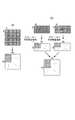
動画像復号化装置210は、図21に示すように、機能的な構成要素として、可変長復号化部2101と、ステレオ/インターレース動きベクトル復元部2102と、ステレオ/インターレース動き補償部2103と、フレームメモリ2104と、ステレオ/インターレース空間予測部2105と、スイッチ2106と、逆量子化部2107と、ステレオ/インターレース逆直交変換部2108と、加算器2109とを備えて構成される。以下、各構成要素について説明する。 As shown in FIG. 21, the moving
可変長復号化部2101は、圧縮ストリーム1436を受信した後、圧縮ストリーム1436を復号化することで、シーケンスの先頭を表す同期記号およびシーケンスヘッダ、フレームヘッダ、スライスヘッダ、マクロブロックヘッダと、画像の種別に関する情報(ステレオ画像識別子)と、「マクロブロック単位の予測モードがフレーム画像でのフレーム間予測であるかフィールド画像でのフレーム間予測であるかの情報、または、予測モードがフレーム画像でのフレーム内予測であるかフィールド画像でのフレーム内予測であるかの情報」とを合わせた信号2134に復号し、当該信号2134を、ステレオ/インターレース動きベクトル復元部2102と、ステレオ/インターレース空間予測部2105と、ステレオ/インターレース逆直交変換部2108とに送る。また、可変長復号化部2101は、マクロブロック符号化情報として、マクロブロック単位で予測モードと量子化直交変換係数を復号する。 After receiving the
また、予測モードがフレーム間予測モードである場合、可変長復号化部2101は、動きベクトル差分値と参照フレーム番号の復号も合わせて行う。なお、可変長復号化部2101は、復号した量子化直交変換係数2122を逆量子化部2107に送る。 When the prediction mode is the inter-frame prediction mode, the variable
また、予測モードがフレーム間予測モードである場合、可変長復号化部2101は、復号した予測モードと動きベクトル差分値と参照フレーム番号とを含む信号2121をステレオ/インターレース動きベクトル復元部2102に送るとともに、復元した予測モード2126をスイッチ2106に送る。一方、予測モードがフレーム内予測モードである場合、可変長復号化部2101は、復号した予測モード2126をスイッチ2106およびステレオ/インターレース空間予測部2105に送る。 When the prediction mode is the inter-frame prediction mode, the variable
予測モードがフレーム間予測モードである場合、ステレオ/インターレース動きベクトル復元部2102は、可変長復号化部2101から送信された信号2134と、動きベクトル差分値と、復号化済みの隣接ブロックの動きベクトル2124から算出した動きベクトル予測値とを用いて動きベクトルを復元し、上記の信号2134と、復元で得られた動きベクトル、予測モードおよび参照フレーム番号を含む信号2123とをステレオ/インターレース動き補償部2103に送る。 When the prediction mode is the inter-frame prediction mode, the stereo / interlace motion
より詳細には、ステレオ/インターレース動きベクトル復元部2102は、復号化対象の画像(以下「復号画像」という)がステレオ画像で(即ち、ステレオ画像識別子が「1」の場合)、予測モードが「フレーム画像でのフレーム間予測」である場合、可変長復号化部2101から送信された動きベクトル差分値と、復号化済みの隣接ブロックの動きベクトル2124から算出した動きベクトル予測値とを用いて、マクロブロック単位でのフレーム画像の動きベクトルを復元する。一方、復号画像がステレオ画像で(即ち、ステレオ画像識別子が「1」の場合)、予測モードが「フィールド画像でのフレーム間予測」である場合、可変長復号化部2101から送信された動きベクトル差分値と、復号化済みの隣接ブロックの動きベクトル2124から算出した動きベクトル予測値とを用いて、左フィールド画像と右フィールド画像の各フィールド単位での動きベクトルを復元する。 More specifically, the stereo / interlaced motion
また、ステレオ/インターレース動きベクトル復元部2102は、復号画像がインターレース画像で(即ち、ステレオ画像識別子が「0」の場合)、予測モードが「フレーム画像でのフレーム間予測」である場合、可変長復号化部2101から送信された動きベクトル差分値と、復号化済みの隣接ブロックの動きベクトル2124から算出した動きベクトル予測値とを用いて、マクロブロック単位でのフレーム画像の動きベクトルを復元する。一方、復号画像がインターレース画像で(即ち、ステレオ画像識別子が「0」の場合)、予測モードが「フィールド画像でのフレーム間予測」である場合、可変長復号化部2101から送信された動きベクトル差分値と、復号化済みの隣接ブロックの動きベクトル2124から算出した動きベクトル予測値とを用いて、上フィールド画像と下フィールド画像の各フィールド単位での動きベクトルを復元する。 Also, the stereo / interlaced motion
ステレオ/インターレース動き補償部2103は、ステレオ/インターレース動きベクトル復元部2102から送られた信号2134と、動きベクトルと、予測モードと、参照フレーム番号とに基づいて、フレームメモリ2104から送信される参照フレーム画像2127を用いて、予測画像信号2125を生成し、スイッチ2106に送る。なお、フレームメモリ2104には、過去の復号化済みのフレーム画像信号が格納されている。 The stereo / interlace motion compensation unit 2103 receives the reference frame transmitted from the
より詳細には、ステレオ/インターレース動き補償部2103は、復号画像がステレオ画像で(即ち、ステレオ画像識別子が「1」の場合)、予測モードが「フレーム画像でのフレーム間予測」である場合、ステレオ/インターレース動きベクトル復元部2102から送信された信号2134と、動きベクトルと、予測モードと、参照フレーム番号とに基づいて、フレームメモリ2104から送信される参照画像2127を用いて、マクロブロック単位でのフレーム画像の予測画像信号2125を生成する。一方、復号画像がステレオ画像で(即ち、ステレオ画像識別子が「1」の場合)、予測モードが「フィールド画像でのフレーム間予測」である場合、ステレオ/インターレース動きベクトル復元部2102から送信された信号2134と、動きベクトルと、予測モードと、参照フレーム番号とに基づいて、フレームメモリ2104から送信される参照画像2127を用いて、左フィールド画像と右フィールド画像の各フィールド単位で予測画像信号を生成した後、左フィールドの予測画像信号と右フィールドの予測画像信号とを縦1列ごとに交互に並べて予測画像信号2125を作成する。 More specifically, the stereo / interlace motion compensation unit 2103, when the decoded image is a stereo image (that is, when the stereo image identifier is “1”) and the prediction mode is “inter-frame prediction with a frame image”, Based on the
また、ステレオ/インターレース動き補償部2103は、復号画像がインターレース画像(即ち、ステレオ画像識別子が「0」の場合)で、予測モードが「フレーム画像でのフレーム間予測」である場合、ステレオ/インターレース動きベクトル復元部2102から送信された信号2134と、動きベクトルと、予測モードと、参照フレーム番号とに基づいて、フレームメモリ2104から送信される参照画像2127を用いて、マクロブロック単位でのフレーム画像の予測画像信号2125を生成する。一方、ステレオ/インターレース動き補償部2103は、復号画像がインターレース画像(即ち、ステレオ画像識別子が「0」の場合)で、予測モードが「フィールド画像でのフレーム間予測」である場合、ステレオ/インターレース動きベクトル復元部2102から送信された信号2134と、動きベクトルと、予測モードと、参照フレーム番号とに基づいて、フレームメモリ2104から送信される参照画像2127を用いて、上フィールド画像と下フィールド画像の各フィールド単位で予測画像信号を生成した後、上フィールドの予測画像信号と下フィールドの予測画像信号とを横1行ごとに交互に並べて予測画像信号2125を作成する。 Also, the stereo / interlace motion compensation unit 2103, when the decoded image is an interlaced image (that is, when the stereo image identifier is “0”) and the prediction mode is “inter-frame prediction with a frame image”, is stereo / interlaced. Based on the
また、予測モードが「フレーム内予測モード」である場合、ステレオ/インターレース空間予測部2105は、符号化済みの近傍ブロックの画像信号(参照画像信号2127)を参照して予測画像信号2128を生成し、スイッチ2106に送る。 When the prediction mode is “intraframe prediction mode”, the stereo / interlace
より詳細には、ステレオ/インターレース空間予測部2105は、復号画像がステレオ画像で(即ち、ステレオ画像識別子が「1」の場合)、予測モードが「フレーム画像でのフレーム内予測」である場合、可変長復号化部2101から送信された信号2134と予測モード2126とに基づいて、フレームメモリ2104から送信される参照画像2127を用いて、マクロブロック単位でのフレーム画像の予測画像信号2128を生成する。一方、復号画像がステレオ画像で(即ち、ステレオ画像識別子が「1」の場合)、予測モードが「フィールド画像でのフレーム内予測」である場合、ステレオ/インターレース空間予測部2105は、可変長復号化部2101から送信された信号2134と予測モード2126とに基づいて、フレームメモリ2104から送信される参照画像2127を用いて、左フィールド画像と右フィールド画像の各フィールド単位で予測画像信号を生成した後、左フィールドの予測画像信号と右フィールドの予測画像信号とを縦1列ごとに交互に並べて予測画像信号2128を作成する。 More specifically, the stereo / interlace
また、ステレオ/インターレース空間予測部2105は、復号画像がインターレース画像で(即ち、ステレオ画像識別子が「0」の場合)、予測モードが「フレーム画像でのフレーム内予測」である場合、可変長復号化部2101から送信された信号2134と予測モード2126とに基づいて、フレームメモリ2104から送信される参照画像2127を用いて、マクロブロック単位でのフレーム画像の予測画像信号2128を生成する。一方、復号画像がインターレース画像で(即ち、ステレオ画像識別子が「0」の場合)、予測モードが「フィールド画像でのフレーム内予測」である場合、ステレオ/インターレース空間予測部2105は、可変長復号化部2101から送信された信号2134と予測モード2126とに基づいて、フレームメモリ2104から送信される参照画像2127を用いて、上フィールド画像と下フィールド画像の各フィールド単位で予測画像信号を生成した後、上フィールドの予測画像信号と下フィールドの予測画像信号とを横1行ごとに交互に並べて予測画像信号2128を作成する。 Also, the stereo / interlace
次に、スイッチ2106が、可変長復号化部2101から送信された予測モード2126に応じて、予測画像信号2125と予測画像信号2128のうちいずれかを選択し、選択した信号を予測画像信号2129として加算器2109に送る。 Next, the switch 2106 selects either the
一方、逆量子化部2107は、可変長復号化部2101により送信された量子化直交変換係数2122を逆量子化することで、量子化直交変換係数2122を直交変換係数2130に復元し、ステレオ/インターレース逆直交変換部2108に送る。 On the other hand, the
ステレオ/インターレース逆直交変換部2108は、直交変換係数2130を逆直交変換することで、直交変換係数2130を予測残差信号2131に復号する。 The stereo / interlace inverse
ステレオ/インターレース逆直交変換部2108に関するより詳細な説明は、動画像符号化装置140のステレオ/インターレース逆直交変換部1412と同様であるので、再度、図19および図20を使って説明する。 A more detailed description of the stereo / interlace inverse
入力画像がステレオ画像であった場合(即ち、ステレオ画像識別子が「1」の場合)における予測残差信号の画素配置変更を図19に示す。予測モードが「フレーム画像でのフレーム間予測」または「フレーム画像でのフレーム内予測」の場合は、ステレオ/インターレース逆直交変換部2108は、図19(a)のように4画素×4ラインのブロックごとに逆直交変換した画素配置を変更することなく予測残差信号2131を生成する。一方、予測モードが「フィールド画像でのフレーム間予測」または「フィールド画像でのフレーム内予測」の場合は、ステレオ/インターレース逆直交変換部2108は、図19(b)のように逆直交変換した左フィールド予測残差信号と右フィールド予測残差信号とを縦1列ごとに交互に並べて合成することで、予測残差信号2131を生成する。 FIG. 19 shows the pixel arrangement change of the prediction residual signal when the input image is a stereo image (that is, when the stereo image identifier is “1”). When the prediction mode is “inter-frame prediction with a frame image” or “intra-frame prediction with a frame image”, the stereo / interlace inverse
また、入力画像がインターレース画像であった場合(即ち、ステレオ画像識別子が「0」の場合)における予測残差信号の画素配置変更を図20に示す。予測モードが「フレーム画像でのフレーム間予測」または「フレーム画像でのフレーム内予測」の場合は、ステレオ/インターレース逆直交変換部2108は、図20(a)のように4画素×4ラインのブロックごとに逆直交変換した画素配置を変更することなく予測残差信号2131を生成する。一方、予測モードが「フィールド画像でのフレーム間予測」または「フィールド画像でのフレーム内予測」の場合は、ステレオ/インターレース逆直交変換部2108は、図20(b)のように逆直交変換した上フィールド予測残差信号と下フィールド予測残差信号とを横1行ごとに交互に並べて合成することで、予測残差信号2131を生成する。 Further, FIG. 20 shows the pixel arrangement change of the prediction residual signal when the input image is an interlaced image (that is, when the stereo image identifier is “0”). When the prediction mode is “inter-frame prediction with a frame image” or “intra-frame prediction with a frame image”, the stereo / interlace inverse
加算器2109は、スイッチ2106から送信された予測画像信号2129と、ステレオ/インターレース逆直交変換部2108から送信された予測残差信号2131とを加算することで、フレーム画像信号2132として復号する。この加算器2109は、特許請求の範囲に記載した「画像データ生成部」に対応し、フレーム画像信号2132は、特許請求の範囲に記載した「画像データ」に対応する。 The
復号されたフレーム画像信号2132は、以降の復号化処理に用いられるため、参照フレーム画像信号としてフレームメモリ2104に格納される。ここで、フレーム画像信号2132は、動画像符号化装置140における同一番号のフレーム画像信号1439と同一の値となる。また、動きベクトルや参照フレーム番号に関する情報も、参照フレーム画像信号に含まれ同時に格納される。 The decoded
最後に、フレーム画像信号2133は、所定の表示タイミングで表示デバイス(図示せず)へ出力され、入力映像信号(動画像信号)1421が再生される。 Finally, the
以上述べた第2実施形態によれば、縦1列ごとに交互に左目画像と右目画像とが配置されたステレオ動画像信号に対し、フレーム画像として、または左フィールドと右フィールドからなるフィールド画像として、符号化および復号化を行うことにより、左目画像と右目画像の相関性を利用して、データ圧縮の効率を向上させることができる。 According to the second embodiment described above, as a frame image or a field image composed of a left field and a right field, a stereo moving image signal in which a left-eye image and a right-eye image are alternately arranged every vertical column. By performing the encoding and decoding, it is possible to improve the efficiency of data compression by utilizing the correlation between the left eye image and the right eye image.
また、入力したステレオ動画像信号と同じ画素配置の出力画像が得られるため、パララックスバリア方式の立体動画像表示装置で表示する場合に、復号化処理後の画像信号のラインの順番を変更し直すことなく、入力画像と同じ画像信号を得ることができる。 In addition, since an output image having the same pixel arrangement as the input stereo moving image signal is obtained, the order of the lines of the image signal after decoding processing is changed when displaying on a parallax barrier type stereoscopic moving image display device. The same image signal as the input image can be obtained without correction.
さらに、縦1列ごとに交互に左目画像と右目画像が配置されたステレオ動画像信号、および横1行ごとに交互に奇数行画像と偶数行画像が配置されたインターレース動画像信号に対し、同一の動画像符号化装置で符号化を行うことができるとともに、同一の動画像復号化装置で復号化を行うことができ、装置の有効利用が可能である。 Furthermore, it is the same for a stereo moving image signal in which left-eye images and right-eye images are alternately arranged for each vertical column, and an interlaced moving image signal in which odd-numbered row images and even-numbered row images are alternately arranged for each horizontal row. Can be encoded by the same moving picture encoding apparatus, and can be decoded by the same moving picture decoding apparatus, so that the apparatus can be used effectively.
なお、上記では、入力画像を、縦に2つに分割又は横に2つに分割することで得られる2つのフィールド画像に分離して、フレーム間予測又はフレーム内予測を行う例を示したが、入力画像の分離方法はこれに限定されるものではなく、入力画像を斜めの境界線によって分離してもよいし、上下方向に3つ以上に分離してもよいし、左右方向に3つ以上に分離してもよい。 In the above, an example is shown in which the input image is divided into two field images obtained by dividing the input image vertically into two or divided into two horizontally, and inter-frame prediction or intra-frame prediction is performed. The input image separation method is not limited to this, and the input image may be separated by an oblique boundary line, or may be separated into three or more in the vertical direction, or three in the horizontal direction. You may isolate | separate above.
さて、以下では図22〜図25を用いて、上記の各実施形態の符号化処理プログラムおよび復号化処理プログラムについて概説する。 Now, the encoding processing program and the decoding processing program of each of the above embodiments will be outlined below with reference to FIGS.
図22には、第1実施形態の動画像符号化処理に関する動画像符号化プログラム910の構成を示す。この図22に示すように、動画像符号化プログラム910は、処理を統括するメインモジュール911と、動画像種別判定モジュール912と、動画像回転モジュール913と、動画像インターレース符号化モジュール914と、ステレオ画像識別子符号化モジュール915と、多重化モジュール916とを備える。動画像種別判定モジュール912、動画像回転モジュール913、動画像インターレース符号化モジュール914、ステレオ画像識別子符号化モジュール915、多重化モジュール916がコンピュータに行わせる機能はそれぞれ、前述した図3の動画像種別判定部301、動画像回転部303、動画像インターレース符号化部305、ステレオ画像識別子符号化部306、多重化部307の機能に相当する。 FIG. 22 shows a configuration of a moving
図23には、第1実施形態の動画像復号化処理に関する動画像復号化プログラム920の構成を示す。この図23に示すように、動画像復号化プログラム920は、処理を統括するメインモジュール921と、分離モジュール922と、動画像インターレース復号化モジュール923と、ステレオ画像識別子復号化モジュール924と、処理制御モジュール925とを備える。分離モジュール922、動画像インターレース復号化モジュール923、ステレオ画像識別子復号化モジュール924がコンピュータに行わせる機能はそれぞれ、前述した図11の分離部1101、動画像インターレース復号化部1102、ステレオ画像識別子復号化部1103の機能に相当する。また、処理制御モジュール925がコンピュータに行わせる機能は、図11の動画像逆回転部1105、スイッチ1104および1106の機能に相当する。 FIG. 23 shows the configuration of a moving
図24には、第2実施形態の動画像符号化処理に関する動画像符号化プログラム930の構成を示す。この図24に示すように、動画像符号化プログラム930は、処理を統括するメインモジュール931と、動画像種別判定モジュール932と、動き検出モジュール933と、動き補償モジュール934と、空間予測モジュール935と、直交変換モジュール936と、可変長符号化モジュール937と、逆直交変換モジュール938とを備える。動画像種別判定モジュール932、動き検出モジュール933、動き補償モジュール934、空間予測モジュール935がコンピュータに行わせる機能はそれぞれ、前述した図14の動画像種別判定部1401、ステレオ/インターレース動き検出部1402、ステレオ/インターレース動き補償部1403、ステレオ/インターレース空間予測部1405の機能に相当する。また、直交変換モジュール936がコンピュータに行わせる機能は、図14のスイッチ1406、減算器1407およびステレオ/インターレース直交変換部1408の機能に相当する。可変長符号化モジュール937がコンピュータに行わせる機能は、図14の量子化部1409および可変長符号化部1410の機能に相当する。逆直交変換モジュール938がコンピュータに行わせる機能は、図14の量子化部1409、逆量子化部1411およびステレオ/インターレース逆直交変換部1412の機能に相当する。 FIG. 24 shows the configuration of a moving
図25には、第2実施形態の動画像復号化処理に関する動画像復号化プログラム940の構成を示す。この図25に示すように、動画像復号化プログラム940は、処理を統括するメインモジュール941と、可変長復号化モジュール942と、動きベクトル復元モジュール943と、動き補償モジュール944と、空間予測モジュール945と、逆直交変換モジュール946と、画像データ生成モジュール947とを備える。可変長復号化モジュール942、動きベクトル復元モジュール943、動き補償モジュール944、空間予測モジュール945がコンピュータに行わせる機能はそれぞれ、前述した図21の可変長復号化部2101、ステレオ/インターレース動きベクトル復元部2102、ステレオ/インターレース動き補償部2103、ステレオ/インターレース空間予測部2105の機能に相当する。また、逆直交変換モジュール946がコンピュータに行わせる機能は、図21の逆量子化部2107およびステレオ/インターレース逆直交変換部2108の機能に相当する。画像データ生成モジュール947がコンピュータに行わせる機能は、図21の加算器2109の機能に相当する。 FIG. 25 shows the configuration of a moving
なお、上記の各プログラムは、コンピュータ読取り可能な記録媒体(以下、単に「記録媒体」と記す)に記録されて流通してもよいし、その一部若しくは全部を他の機器から通信回線等の伝送媒体を介して、本発明に係る動画像符号化装置または動画像復号化装置により受信され、記録される構成にしてもよい。反対に、上記の各プログラムは、本発明に係る動画像符号化装置または動画像復号化装置から伝送媒体を介して他の機器に伝送され、インストールされる構成としてもよい。 Each of the above-mentioned programs may be recorded and distributed on a computer-readable recording medium (hereinafter simply referred to as “recording medium”), or a part or all of the program may be transmitted from another device to a communication line or the like. It may be configured to be received and recorded by the moving picture coding apparatus or moving picture decoding apparatus according to the present invention via a transmission medium. On the contrary, each of the above programs may be transmitted from the moving picture encoding apparatus or moving picture decoding apparatus according to the present invention to another device via a transmission medium and installed.
10…フィルター、11…液晶ディスプレイ、12…スリット板、13…左目、14…右目、30、140…動画像符号化装置、110、210…動画像復号化装置、301…動画像種別判定部、302…スイッチ、303…動画像回転部、304…スイッチ、305…動画像インターレース符号化部、306…ステレオ画像識別子符号化部、307…多重化部、910、930…動画像符号化プログラム、920、940…動画像符号化プログラム、1101…分離部、1102…動画像インターレース復号化部、1103…ステレオ画像識別子復号化部、1104…スイッチ、1105…動画像逆回転部、1106…スイッチ、1401…動画像種別判定部、1402…ステレオ/インターレース動き検出部、1403…ステレオ/インターレース動き補償部、1404…フレームメモリ、1405…ステレオ/インターレース空間予測部、1406…スイッチ、1407…減算器、1408…ステレオ/インターレース直交変換部、1409…量子化部、1410…可変長符号化部、1411…逆量子化部、1412…ステレオ/インターレース逆直交変換部、1413…加算器、2101…可変長復号化部、2102…ステレオ/インターレース動きベクトル復元部、2103…ステレオ/インターレース動き補償部、2104…フレームメモリ、2105…ステレオ/インターレース空間予測部、2106…スイッチ、2107…逆量子化部、2108…ステレオ/インターレース逆直交変換部、2109…加算器。 DESCRIPTION OF
Claims (4)
Translated fromJapanese符号化対象の動画像がステレオ動画像であるか否かを判定する動画像種別判定部と、
符号化対象の動画像がステレオ動画像であると判定された場合に、当該動画像における縦方向が横方向に変わるように、当該動画像を所定方向に所定角度回転させる動画像回転部と、
ステレオ動画像でないと判定された動画像、およびステレオ動画像であると判定され前記所定角度回転した動画像をインターレース符号化する動画像インターレース符号化部と、
符号化対象の動画像がステレオ動画像であるか否かを示す情報、並びに、前記動画像回転部によって符号化対象の動画像に対し行われた回転の方向および角度に関する情報を含むステレオ画像識別子を符号化するステレオ画像識別子符号化部と、
前記動画像インターレース符号化部によるインターレース符号化で得られた符号化ビットストリームと、前記ステレオ画像識別子符号化部による符号化で得られたステレオ画像識別子の符号とを多重化することで多重化符号化ビットストリームを作成する多重化部と、
を備える動画像符号化装置。A moving image encoding device that encodes a stereo moving image in which a right eye image and a left eye image are alternately arranged in a vertical column and an interlaced moving image in which an odd row image and an even row image are alternately arranged in a horizontal row. There,
A moving image type determination unit that determines whether the moving image to be encoded is a stereo moving image;
A moving image rotating unit that rotates the moving image by a predetermined angle in a predetermined direction so that the vertical direction in the moving image is changed to a horizontal direction when it is determined that the moving image to be encoded is a stereo moving image;
A moving image interlace encoding unit that interlace-codes a moving image determined not to be a stereo moving image and a moving image determined to be a stereo moving image and rotated by the predetermined angle;
Stereo image identifierincluding information indicating whether or not the moving image to be encoded is a stereo moving image,and information on the direction and angle of rotation performed on the moving image to be encoded by the moving image rotating unit. A stereo image identifier encoding unit for encoding
A multiplexed code is obtained by multiplexing a coded bitstream obtained by interlace coding by the moving image interlace coding unit and a stereo image identifier code obtained by coding by the stereo image identifier coding unit. A multiplexing unit for creating a generalized bitstream;
A video encoding device comprising:
受信された多重化符号化ビットストリームを、動画像の符号化ビットストリームとステレオ画像識別子の符号とに分離する分離部と、
分離された前記動画像の符号化ビットストリームをインターレース復号化する動画像インターレース復号化部と、
分離された前記ステレオ画像識別子の符号を復号化するステレオ画像識別子復号化部と、
前記ステレオ画像識別子復号化部による復号化で得られたステレオ画像識別子に含まれる前記動画像がステレオ動画像であるか否かを示す情報に基づき、前記動画像がステレオ動画像である場合、前記復号化で得られたステレオ画像識別子に含まれる符号化時に前記動画像に対し行われた回転の方向および角度に関する情報に基づいて、前記回転の方向とは逆方向に前記角度だけ前記動画像を回転させる画像処理を、前記動画像インターレース復号化部によるインターレース復号化で得られた動画像信号に対し行う処理制御部と、
を備える動画像復号化装置。A moving image decoding apparatus that decodes a stereo moving image in which right-eye images and left-eye images are alternately arranged in vertical columns and an interlaced moving image in which odd-numbered rows and even-numbered rows are alternately arranged in horizontal rows. There,
A separator that separates the received multiplexed encoded bitstream into a moving image encoded bitstream and a stereo image identifier code;
A moving image interlace decoding unit for interlace decoding the encoded bit stream of the separated moving image;
A stereo image identifier decoding unit for decoding the code of the separated stereo image identifier;
When themoving image is a stereo moving image based on information indicating whether the moving image included in the stereo image identifier obtained by decoding by the stereo image identifier decoding unitis a stereo moving image, Based on information about the direction and angle of rotation performed on the moving image at the time of encoding included in the stereo image identifier obtained by decoding, the moving image is moved by the angle in the direction opposite to the direction of rotation. A processing control unit that performsimage processing to berotated on a moving image signal obtained by interlace decoding by the moving image interlace decoding unit;
A video decoding device comprising:
符号化対象の動画像がステレオ動画像であるか否かを判定する動画像種別判定ステップと、
符号化対象の動画像がステレオ動画像であると判定された場合に、当該動画像における縦方向が横方向に変わるように、当該動画像を所定方向に所定角度回転させる動画像回転ステップと、
ステレオ動画像でないと判定された動画像、およびステレオ動画像であると判定され前記所定角度回転した動画像をインターレース符号化する動画像インターレース符号化ステップと、
符号化対象の動画像がステレオ動画像であるか否かを示す情報、並びに、前記動画像回転ステップによって符号化対象の動画像に対し行われた回転の方向および角度に関する情報を含むステレオ画像識別子を符号化するステレオ画像識別子符号化ステップと、
前記インターレース符号化で得られた符号化ビットストリームと、前記符号化で得られたステレオ画像識別子の符号とを多重化することで多重化符号化ビットストリームを作成する多重化ステップと、
を有する動画像符号化方法。A moving image encoding method for encoding a stereo moving image in which a right eye image and a left eye image are alternately arranged in a vertical column, and an interlaced moving image in which an odd row image and an even row image are alternately arranged in a horizontal row. There,
A moving image type determining step for determining whether or not the moving image to be encoded is a stereo moving image;
A moving image rotation step for rotating the moving image by a predetermined angle in a predetermined direction so that the vertical direction in the moving image is changed to the horizontal direction when it is determined that the moving image to be encoded is a stereo moving image;
A moving image interlaced encoding step for interlace encoding a moving image determined not to be a stereo moving image and a moving image determined to be a stereo moving image and rotated by the predetermined angle;
Stereo image identifierincluding information indicating whether or not the moving image to be encoded is a stereo moving image,and information on the direction and angle of rotation performed on the moving image to be encoded by the moving image rotation step. A stereo image identifier encoding step for encoding
A multiplexing step of creating a multiplexed encoded bitstream by multiplexing the encoded bitstream obtained by the interlaced encoding and the stereo image identifier code obtained by the encoding;
A video encoding method comprising:
受信された多重化符号化ビットストリームを、動画像の符号化ビットストリームとステレオ画像識別子の符号とに分離する分離ステップと、
分離された前記動画像の符号化ビットストリームをインターレース復号化する動画像インターレース復号化ステップと、
分離された前記ステレオ画像識別子の符号を復号化するステレオ画像識別子復号化ステップと、
前記復号化で得られたステレオ画像識別子に含まれる前記動画像がステレオ動画像であるか否かを示す情報に基づき、前記動画像がステレオ動画像である場合、前記復号化で得られたステレオ画像識別子に含まれる符号化時に前記動画像に対し行われた回転の方向および角度に関する情報に基づいて、前記回転の方向とは逆方向に前記角度だけ前記動画像を回転させる画像処理を、前記インターレース復号化で得られた動画像信号に対し行う処理制御ステップと、
を有する動画像復号化方法。
A moving image decoding method for decoding a stereo moving image in which right-eye images and left-eye images are alternately arranged every vertical column, and an interlaced moving image in which odd-numbered rows and even-numbered rows are alternately arranged every horizontal row. There,
Separating the received multiplexed encoded bitstream into a moving image encoded bitstream and a stereo image identifier code;
A moving image interlace decoding step for interlace decoding the separated encoded video bit stream;
A stereo image identifier decoding step of decoding the code of the separated stereo image identifier;
When themoving image is a stereo moving image based on information indicating whether the moving image included in the stereo image identifier obtained by the decodingis a stereo moving image, the stereo obtained by the decoding Based on information about the direction and angle of rotation performed on the moving image at the time of encoding included in the image identifier, image processing forrotating the moving image by the angle in a direction opposite to the rotation direction , Processing control steps to be performed on a moving image signal obtained by interlace decoding;
A video decoding method comprising:
Priority Applications (8)
| Application Number | Priority Date | Filing Date | Title |
|---|---|---|---|
| JP2004144074AJP4421940B2 (en) | 2004-05-13 | 2004-05-13 | Moving picture coding apparatus and method, and moving picture decoding apparatus and method |
| US11/125,209US7746931B2 (en) | 2004-05-13 | 2005-05-10 | Moving picture encoding apparatus and method, moving picture decoding apparatus and method |
| EP20110187881EP2416580A2 (en) | 2004-05-13 | 2005-05-11 | Moving picture encoding apparatus and method, moving picture decoding apparatus and method |
| EP20100154896EP2205003A3 (en) | 2004-05-13 | 2005-05-11 | Moving picture encoding apparatus and method, moving picture decoding apparatus and method |
| EP20050010269EP1596609A3 (en) | 2004-05-13 | 2005-05-11 | Moving picture encoding apparatus and method, moving picture decoding apparatus and method |
| CN2008101710869ACN101400000B (en) | 2004-05-13 | 2005-05-13 | Moving picture encoding apparatus and method, moving picture decoding apparatus and method |
| CNB2005100702876ACN100488260C (en) | 2004-05-13 | 2005-05-13 | Moving image encoding device and method, and moving image decoding device and method |
| US12/508,066US8254458B2 (en) | 2004-05-13 | 2009-07-23 | Moving picture encoding apparatus and method, moving picture decoding apparatus and method |
Applications Claiming Priority (1)
| Application Number | Priority Date | Filing Date | Title |
|---|---|---|---|
| JP2004144074AJP4421940B2 (en) | 2004-05-13 | 2004-05-13 | Moving picture coding apparatus and method, and moving picture decoding apparatus and method |
Related Child Applications (1)
| Application Number | Title | Priority Date | Filing Date |
|---|---|---|---|
| JP2009146683ADivisionJP2009260983A (en) | 2009-06-19 | 2009-06-19 | Moving image encoding device and method, and moving image decoding device and method |
Publications (2)
| Publication Number | Publication Date |
|---|---|
| JP2005328299A JP2005328299A (en) | 2005-11-24 |
| JP4421940B2true JP4421940B2 (en) | 2010-02-24 |
Family
ID=34936414
Family Applications (1)
| Application Number | Title | Priority Date | Filing Date |
|---|---|---|---|
| JP2004144074AExpired - Fee RelatedJP4421940B2 (en) | 2004-05-13 | 2004-05-13 | Moving picture coding apparatus and method, and moving picture decoding apparatus and method |
Country Status (4)
| Country | Link |
|---|---|
| US (2) | US7746931B2 (en) |
| EP (3) | EP2416580A2 (en) |
| JP (1) | JP4421940B2 (en) |
| CN (2) | CN101400000B (en) |
Families Citing this family (33)
| Publication number | Priority date | Publication date | Assignee | Title |
|---|---|---|---|---|
| EP2733952A1 (en)* | 2005-10-21 | 2014-05-21 | Electronics and Telecommunications Research Institute | Method for encoding moving picture using adaptive scanning |
| US9516326B1 (en)* | 2005-12-09 | 2016-12-06 | Nvidia Corporation | Method for rotating macro-blocks of a frame of a video stream |
| JP2007180982A (en)* | 2005-12-28 | 2007-07-12 | Victor Co Of Japan Ltd | Device, method, and program for decoding image |
| JP2007180981A (en)* | 2005-12-28 | 2007-07-12 | Victor Co Of Japan Ltd | Device, method, and program for encoding image |
| ZA200805337B (en)* | 2006-01-09 | 2009-11-25 | Thomson Licensing | Method and apparatus for providing reduced resolution update mode for multiview video coding |
| US20100091845A1 (en)* | 2006-03-30 | 2010-04-15 | Byeong Moon Jeon | Method and apparatus for decoding/encoding a video signal |
| KR100949981B1 (en)* | 2006-03-30 | 2010-03-29 | 엘지전자 주식회사 | A method and apparatus for decoding/encoding a video signal |
| KR100800750B1 (en) | 2006-08-04 | 2008-02-01 | 삼성전자주식회사 | 3D image generating device and method for generating and outputting 3D image |
| JP4993676B2 (en)* | 2006-09-01 | 2012-08-08 | キヤノン株式会社 | Image coding apparatus and image coding method |
| CA2665781C (en) | 2006-10-30 | 2014-02-18 | Nippon Telegraph And Telephone Corporation | Predicted reference information generating method, video encoding and decoding methods, apparatuses therefor, programs therefor, and storage media which store the programs |
| KR101319535B1 (en)* | 2006-12-26 | 2013-10-21 | 삼성전자주식회사 | Device of processing image and method thereof |
| ES2675164T3 (en)* | 2007-04-12 | 2018-07-09 | Dolby International Ab | Mosaic presentation in video coding and decoding |
| EP2501137A3 (en)* | 2007-06-11 | 2012-12-12 | Samsung Electronics Co., Ltd. | Method and apparatus for generating header information of stereoscopic image |
| US8471893B2 (en)* | 2007-06-26 | 2013-06-25 | Samsung Electronics Co., Ltd. | Method and apparatus for generating stereoscopic image bitstream using block interleaved method |
| JP4892450B2 (en)* | 2007-10-17 | 2012-03-07 | パナソニック株式会社 | Image coding apparatus and image coding method |
| KR101591085B1 (en)* | 2008-05-19 | 2016-02-02 | 삼성전자주식회사 | Apparatus and method for creating and playing video files |
| KR20100040640A (en) | 2008-10-10 | 2010-04-20 | 엘지전자 주식회사 | Receiving system and method of processing data |
| IT1393713B1 (en)* | 2008-10-21 | 2012-05-08 | S I R I Société Internationale De Rech Ind S A | SYSTEM TO CODIFY AND DECODE STEREOSCOPIC IMAGES |
| JP4960400B2 (en)* | 2009-03-26 | 2012-06-27 | 株式会社東芝 | Stereo image encoding method and stereo image decoding method |
| JP5627860B2 (en) | 2009-04-27 | 2014-11-19 | 三菱電機株式会社 | 3D image distribution system, 3D image distribution method, 3D image distribution device, 3D image viewing system, 3D image viewing method, 3D image viewing device |
| KR20100138806A (en) | 2009-06-23 | 2010-12-31 | 삼성전자주식회사 | Automatic 3D image format conversion method and device therefor |
| US8542737B2 (en)* | 2010-03-21 | 2013-09-24 | Human Monitoring Ltd. | Intra video image compression and decompression |
| MX353107B (en)* | 2010-04-09 | 2017-12-19 | Mitsubishi Electric Corp | Video encoding device and video decoding device. |
| JP5559614B2 (en)* | 2010-04-21 | 2014-07-23 | 日立マクセル株式会社 | Receiving apparatus and receiving method |
| JP5505154B2 (en)* | 2010-07-16 | 2014-05-28 | ソニー株式会社 | Image processing apparatus and image processing method |
| JP4964355B2 (en)* | 2010-09-30 | 2012-06-27 | パナソニック株式会社 | Stereoscopic video encoding apparatus, stereoscopic video imaging apparatus, and stereoscopic video encoding method |
| JP2012257198A (en)* | 2011-05-17 | 2012-12-27 | Canon Inc | Stereoscopic image encoding apparatus, method therefor, and image pickup apparatus having stereoscopic image encoding apparatus |
| JP5815326B2 (en)* | 2011-08-12 | 2015-11-17 | ルネサスエレクトロニクス株式会社 | Video decoding device and image display device |
| CN104160705B (en) | 2012-03-12 | 2018-11-16 | 杜比实验室特许公司 | 3D vision dynamic range coding |
| CN102802012A (en)* | 2012-07-19 | 2012-11-28 | 彩虹集团公司 | Three-dimensional automatic signal identifying method |
| US20160048697A1 (en)* | 2014-08-18 | 2016-02-18 | Spatial Digital Systems, Inc. | Enveloping and de-enveloping for Digital Photos via Wavefront Muxing |
| JP2016226008A (en)* | 2016-07-27 | 2016-12-28 | 日立マクセル株式会社 | Receiving apparatus and receiving method |
| US12106528B2 (en)* | 2021-03-01 | 2024-10-01 | Waymo Llc | Generating scene flow labels for point clouds using object labels |
Family Cites Families (18)
| Publication number | Priority date | Publication date | Assignee | Title |
|---|---|---|---|---|
| JPH01118111A (en) | 1987-10-30 | 1989-05-10 | Sanyo Electric Co Ltd | Focusing mechanism for magnetic recording camera |
| US5253056A (en)* | 1992-07-02 | 1993-10-12 | At&T Bell Laboratories | Spatial/frequency hybrid video coding facilitating the derivatives of variable-resolution images |
| JPH07123447A (en)* | 1993-10-22 | 1995-05-12 | Sony Corp | Method and device for recording image signal, method and device for reproducing image signal, method and device for encoding image signal, method and device for decoding image signal and image signal recording medium |
| US5767898A (en)* | 1994-06-23 | 1998-06-16 | Sanyo Electric Co., Ltd. | Three-dimensional image coding by merger of left and right images |
| JPH0870475A (en) | 1994-06-23 | 1996-03-12 | Sanyo Electric Co Ltd | Method and device for encoding and decoding stereoscopic animation |
| US6055012A (en)* | 1995-12-29 | 2000-04-25 | Lucent Technologies Inc. | Digital multi-view video compression with complexity and compatibility constraints |
| CN1223772A (en)* | 1996-07-03 | 1999-07-21 | 松下电器产业株式会社 | Encoding method, encoding device, decoding and synthesizing method, decoding and synthesizing device, and recording medium for recording multiple image information |
| US6263024B1 (en)* | 1996-12-12 | 2001-07-17 | Matsushita Electric Industrial Co., Ltd. | Picture encoder and picture decoder |
| EP1024672A1 (en)* | 1997-03-07 | 2000-08-02 | Sanyo Electric Co., Ltd. | Digital broadcast receiver and display |
| JP3454675B2 (en) | 1997-06-20 | 2003-10-06 | 三洋電機株式会社 | 3D image transmission method and apparatus |
| JP3519594B2 (en) | 1998-03-03 | 2004-04-19 | Kddi株式会社 | Encoding device for stereo video |
| EP1269761A1 (en)* | 2000-03-31 | 2003-01-02 | Koninklijke Philips Electronics N.V. | Encoding of two correlated sequences of data |
| US6940557B2 (en)* | 2001-02-08 | 2005-09-06 | Micronas Semiconductors, Inc. | Adaptive interlace-to-progressive scan conversion algorithm |
| EP2096871B1 (en) | 2001-09-14 | 2014-11-12 | NTT DoCoMo, Inc. | Coding method, decoding method, coding apparatus, decoding apparatus, image processing system, coding program, and decoding program |
| CA2380105A1 (en)* | 2002-04-09 | 2003-10-09 | Nicholas Routhier | Process and system for encoding and playback of stereoscopic video sequences |
| KR100481732B1 (en)* | 2002-04-20 | 2005-04-11 | 전자부품연구원 | Apparatus for encoding of multi view moving picture |
| JP4154569B2 (en) | 2002-07-10 | 2008-09-24 | 日本電気株式会社 | Image compression / decompression device |
| EP2465184A1 (en) | 2009-08-13 | 2012-06-20 | ABB Research Ltd. | Optimized cooling system for a brushed electrical machine, and a corresponding method |
- 2004
- 2004-05-13JPJP2004144074Apatent/JP4421940B2/ennot_activeExpired - Fee Related
- 2005
- 2005-05-10USUS11/125,209patent/US7746931B2/ennot_activeExpired - Fee Related
- 2005-05-11EPEP20110187881patent/EP2416580A2/ennot_activeWithdrawn
- 2005-05-11EPEP20100154896patent/EP2205003A3/ennot_activeWithdrawn
- 2005-05-11EPEP20050010269patent/EP1596609A3/ennot_activeWithdrawn
- 2005-05-13CNCN2008101710869Apatent/CN101400000B/ennot_activeExpired - Fee Related
- 2005-05-13CNCNB2005100702876Apatent/CN100488260C/ennot_activeExpired - Fee Related
- 2009
- 2009-07-23USUS12/508,066patent/US8254458B2/ennot_activeExpired - Fee Related
Also Published As
| Publication number | Publication date |
|---|---|
| CN101400000B (en) | 2010-10-06 |
| US20090285302A1 (en) | 2009-11-19 |
| EP1596609A3 (en) | 2008-03-12 |
| EP1596609A2 (en) | 2005-11-16 |
| US7746931B2 (en) | 2010-06-29 |
| JP2005328299A (en) | 2005-11-24 |
| EP2416580A2 (en) | 2012-02-08 |
| EP2205003A3 (en) | 2014-12-31 |
| US20050254010A1 (en) | 2005-11-17 |
| CN1697526A (en) | 2005-11-16 |
| CN101400000A (en) | 2009-04-01 |
| EP2205003A2 (en) | 2010-07-07 |
| CN100488260C (en) | 2009-05-13 |
| US8254458B2 (en) | 2012-08-28 |
Similar Documents
| Publication | Publication Date | Title |
|---|---|---|
| JP4421940B2 (en) | Moving picture coding apparatus and method, and moving picture decoding apparatus and method | |
| KR101385884B1 (en) | Method for cording and decording multiview video and apparatus for the same | |
| KR100667830B1 (en) | Method and apparatus for encoding multiview video | |
| EP1878260B1 (en) | Method for scalably encoding and decoding video signal | |
| KR101450670B1 (en) | Block-Based Binocular Image Format Generation Method and Apparatus and Binocular Image Restoration Method and Apparatus | |
| KR100636785B1 (en) | Multi-view stereoscopic imaging system and compression and decompression method applied to it | |
| KR102215951B1 (en) | Decoder and decoding method, as well as encoder and encoding method | |
| EP2538675A1 (en) | Apparatus for universal coding for multi-view video | |
| KR100728009B1 (en) | Method and apparatus for encoding multiview video | |
| RU2680204C2 (en) | Method and device for inducing motion information between temporal points of sub prediction unit | |
| JP2009505604A (en) | Method and apparatus for encoding multi-view video | |
| KR20110124199A (en) | Image processing apparatus and method | |
| KR20140110842A (en) | Image processing device and image processing method | |
| JP4960400B2 (en) | Stereo image encoding method and stereo image decoding method | |
| JP4355914B2 (en) | Multi-view image transmission system and method, multi-view image compression device and method, multi-view image decompression device and method, and program | |
| US9001892B2 (en) | Moving image encoder and moving image decoder | |
| JP5442688B2 (en) | Moving picture coding apparatus and method, and moving picture decoding apparatus and method | |
| JP2009260983A (en) | Moving image encoding device and method, and moving image decoding device and method | |
| KR20120084628A (en) | Apparatus and method for encoding and decoding multi-view image | |
| JP2008034893A (en) | Multi-viewpoint image decoder | |
| JP2013211777A (en) | Image coding device, image decoding device, image coding method, image decoding method and program | |
| HK1159914A (en) | Moving image encoding apparatus and moving image decoding apparatus |
Legal Events
| Date | Code | Title | Description |
|---|---|---|---|
| A621 | Written request for application examination | Free format text:JAPANESE INTERMEDIATE CODE: A621 Effective date:20070405 | |
| A977 | Report on retrieval | Free format text:JAPANESE INTERMEDIATE CODE: A971007 Effective date:20090416 | |
| A131 | Notification of reasons for refusal | Free format text:JAPANESE INTERMEDIATE CODE: A131 Effective date:20090428 | |
| A521 | Written amendment | Free format text:JAPANESE INTERMEDIATE CODE: A523 Effective date:20090619 | |
| TRDD | Decision of grant or rejection written | ||
| A01 | Written decision to grant a patent or to grant a registration (utility model) | Free format text:JAPANESE INTERMEDIATE CODE: A01 Effective date:20091201 | |
| A01 | Written decision to grant a patent or to grant a registration (utility model) | Free format text:JAPANESE INTERMEDIATE CODE: A01 | |
| A61 | First payment of annual fees (during grant procedure) | Free format text:JAPANESE INTERMEDIATE CODE: A61 Effective date:20091203 | |
| FPAY | Renewal fee payment (event date is renewal date of database) | Free format text:PAYMENT UNTIL: 20121211 Year of fee payment:3 | |
| R150 | Certificate of patent or registration of utility model | Free format text:JAPANESE INTERMEDIATE CODE: R150 | |
| FPAY | Renewal fee payment (event date is renewal date of database) | Free format text:PAYMENT UNTIL: 20121211 Year of fee payment:3 | |
| FPAY | Renewal fee payment (event date is renewal date of database) | Free format text:PAYMENT UNTIL: 20131211 Year of fee payment:4 | |
| R250 | Receipt of annual fees | Free format text:JAPANESE INTERMEDIATE CODE: R250 | |
| R250 | Receipt of annual fees | Free format text:JAPANESE INTERMEDIATE CODE: R250 | |
| LAPS | Cancellation because of no payment of annual fees |