JP4420944B2 - In-vehicle engine controller - Google Patents
In-vehicle engine controllerDownload PDFInfo
- Publication number
- JP4420944B2 JP4420944B2JP2007196060AJP2007196060AJP4420944B2JP 4420944 B2JP4420944 B2JP 4420944B2JP 2007196060 AJP2007196060 AJP 2007196060AJP 2007196060 AJP2007196060 AJP 2007196060AJP 4420944 B2JP4420944 B2JP 4420944B2
- Authority
- JP
- Japan
- Prior art keywords
- memory
- microprocessor
- fuel injection
- abnormality
- cylinder
- Prior art date
- Legal status (The legal status is an assumption and is not a legal conclusion. Google has not performed a legal analysis and makes no representation as to the accuracy of the status listed.)
- Expired - Fee Related
Links
Images


Classifications
- F—MECHANICAL ENGINEERING; LIGHTING; HEATING; WEAPONS; BLASTING
- F02—COMBUSTION ENGINES; HOT-GAS OR COMBUSTION-PRODUCT ENGINE PLANTS
- F02D—CONTROLLING COMBUSTION ENGINES
- F02D41/00—Electrical control of supply of combustible mixture or its constituents
- F02D41/24—Electrical control of supply of combustible mixture or its constituents characterised by the use of digital means
- F02D41/26—Electrical control of supply of combustible mixture or its constituents characterised by the use of digital means using computer, e.g. microprocessor
- F02D41/266—Electrical control of supply of combustible mixture or its constituents characterised by the use of digital means using computer, e.g. microprocessor the computer being backed-up or assisted by another circuit, e.g. analogue
- F—MECHANICAL ENGINEERING; LIGHTING; HEATING; WEAPONS; BLASTING
- F02—COMBUSTION ENGINES; HOT-GAS OR COMBUSTION-PRODUCT ENGINE PLANTS
- F02D—CONTROLLING COMBUSTION ENGINES
- F02D41/00—Electrical control of supply of combustible mixture or its constituents
- F02D41/009—Electrical control of supply of combustible mixture or its constituents using means for generating position or synchronisation signals
- F—MECHANICAL ENGINEERING; LIGHTING; HEATING; WEAPONS; BLASTING
- F02—COMBUSTION ENGINES; HOT-GAS OR COMBUSTION-PRODUCT ENGINE PLANTS
- F02D—CONTROLLING COMBUSTION ENGINES
- F02D41/00—Electrical control of supply of combustible mixture or its constituents
- F02D41/24—Electrical control of supply of combustible mixture or its constituents characterised by the use of digital means
- F02D41/26—Electrical control of supply of combustible mixture or its constituents characterised by the use of digital means using computer, e.g. microprocessor
- F02D41/28—Interface circuits
- F—MECHANICAL ENGINEERING; LIGHTING; HEATING; WEAPONS; BLASTING
- F02—COMBUSTION ENGINES; HOT-GAS OR COMBUSTION-PRODUCT ENGINE PLANTS
- F02D—CONTROLLING COMBUSTION ENGINES
- F02D41/00—Electrical control of supply of combustible mixture or its constituents
- F02D41/22—Safety or indicating devices for abnormal conditions
- F02D2041/227—Limping Home, i.e. taking specific engine control measures at abnormal conditions
- F—MECHANICAL ENGINEERING; LIGHTING; HEATING; WEAPONS; BLASTING
- F02—COMBUSTION ENGINES; HOT-GAS OR COMBUSTION-PRODUCT ENGINE PLANTS
- F02D—CONTROLLING COMBUSTION ENGINES
- F02D41/00—Electrical control of supply of combustible mixture or its constituents
- F02D41/02—Circuit arrangements for generating control signals
- F02D41/04—Introducing corrections for particular operating conditions
- F02D41/10—Introducing corrections for particular operating conditions for acceleration
- F02D41/105—Introducing corrections for particular operating conditions for acceleration using asynchronous injection
- F—MECHANICAL ENGINEERING; LIGHTING; HEATING; WEAPONS; BLASTING
- F02—COMBUSTION ENGINES; HOT-GAS OR COMBUSTION-PRODUCT ENGINE PLANTS
- F02D—CONTROLLING COMBUSTION ENGINES
- F02D41/00—Electrical control of supply of combustible mixture or its constituents
- F02D41/22—Safety or indicating devices for abnormal conditions
Landscapes
- Engineering & Computer Science (AREA)
- General Engineering & Computer Science (AREA)
- Chemical & Material Sciences (AREA)
- Combustion & Propulsion (AREA)
- Mechanical Engineering (AREA)
- Computer Hardware Design (AREA)
- Microelectronics & Electronic Packaging (AREA)
- Combined Controls Of Internal Combustion Engines (AREA)
- Debugging And Monitoring (AREA)
- Test And Diagnosis Of Digital Computers (AREA)
Description
Translated fromJapaneseこの発明は、ノイズ誤動作等による偶発的な異常発生に対し、マイクロプロセッサをリセットして、速やかに点検・初期化を行なったうえで再起動するための改良されたマイクロプロセッサの初期化手段を備えた車載エンジン制御装置に関するものである。The present invention comprises an improved microprocessor initialization means for resetting a microprocessor to promptly inspect and initialize it after an accidental abnormality caused by noise malfunction etc. It is related with the vehicle-mounted engine control apparatus.
一般に、運転中のマイクロプロセッサに異常が発生したときに、当該マイクロプロセッサをリセットして、各部を点検したうえで再起動する場合に、安全性を考慮すれば時間をかけて十分な点検を行いたい反面、なるべく運転中断時間を短縮したいという相反する要求がある。例えば、特許文献1(特開2006−150999号公報)には、制御装置の起動時に優先的に機能すべき制御手段に対応した第一種アプリケーションと、その余の制御手段に対応した第二種アプリケーションとに区分して、起動に際しては、優先度の高い第一種アプリケーションのみについてリソース設定を行ない、優先度の低い第二種アプリケーションのリソース設定は、第一種アプリケーションの起動後に行なうという技術が開示されており、複数のアプリケーションを担うハードウェアの制御主体であるECU(電子制御ユニット)が、リセット後再起動されるときに、その再起動処理に伴う特定の重要機能の動作停止時間を短縮することができ、ひいては機能停止に伴うユーザーへの違和感や不快感を低減できる自動車用制御装置が提供されている。In general, when an abnormality occurs in a running microprocessor, when the microprocessor is reset and checked after each part is restarted, a thorough inspection should be performed taking time into consideration when considering safety. On the other hand, there is a conflicting request to reduce the operation interruption time as much as possible. For example, Patent Document 1 (Japanese Patent Application Laid-Open No. 2006-150999) discloses a first type application corresponding to a control unit that should function preferentially when a control device is started, and a second type corresponding to other control units. When starting up, the resource setting is performed only for the first type application with high priority, and the resource setting for the second type application with low priority is performed after starting the first type application. When the ECU (Electronic Control Unit), which is the disclosed hardware controller responsible for multiple applications, is restarted after reset, it shortens the operation stop time of certain important functions that accompany the restart process Control device for automobiles that can reduce discomfort and discomfort to the user due to function stoppage It is provided.
また、特許文献2(特開2003−97345号公報)には、エンジンの噴射制御、点火制御、スロットル制御を実施するためのCPU(マイクロプロセッサ)と、該CPUの動作を監視するためのWD(ウォッチドッグタイマ)回路とを備え、WD回路は、CPUからのWDパルスが所定時間以上反転しなかった場合にCPUに対してリセット信号を出力し、WD回路には、例えばフリップフロップやカウンタ等よりなる記憶部が設けられており、CPUへのリセット信号出力の都度、リセット情報が記憶部に記憶され、前記記憶部を、前記リセット情報としてのリセット回数をカウントするリセットカウンタにて構成し、前記CPUは、再起動時にリセットカウンタの値が所定の閾値以上であればフェイルセーフ処理を実施する車両用電子制御装置が開示されている。Patent Document 2 (Japanese Patent Application Laid-Open No. 2003-97345) discloses a CPU (microprocessor) for performing engine injection control, ignition control, and throttle control, and a WD (Monitor for monitoring the operation of the CPU). Watchdog timer) circuit, and the WD circuit outputs a reset signal to the CPU when the WD pulse from the CPU does not invert for a predetermined time or more. The storage unit is provided, each time a reset signal is output to the CPU, the reset information is stored in the storage unit, the storage unit is configured with a reset counter that counts the number of resets as the reset information, If the value of the reset counter is greater than or equal to a predetermined threshold at the time of restart, the CPU Control apparatus is disclosed.
一方、特許文献3(特開2003−155945号公報)には、内燃機関の始動性を推定する手段と、内燃機関の各気筒の特定クランク角位置に同期してクランク角信号を出力するクランク角検出手段と、特定気筒の基準クランク角を判別する気筒判別手段と、始動時に気筒判別が完了する以前より、全気筒に燃料を同時噴射する手段と、気筒判別が完了した直後より、クランク角信号に同期して気筒毎に順次、独立噴射を開始する手段とを備えた内燃機関の始動時燃料噴射装置において、内燃機関の始動性が所定の水準よりも悪いと推定された場合にだけ、気筒判別完了直後より独立噴射を開始するとともに、他の吸入可能な気筒に燃料を同時噴射する手段を備え、始動性を確保しながら、始動時の不完全燃焼を防止し、始動時のHC排出量を低減することができる内燃機関の始動時燃料噴射制御装置が開示されている。
なお、この発明に関連して特許文献4(特開2004−027976号公報)には、クランク角センサを用いて多気筒車載エンジンの燃料噴射タイミングと点火タイミングを決定するための気筒判別方法が詳しく説明されている。On the other hand, Patent Document 3 (Japanese Patent Laid-Open No. 2003-155945) discloses a means for estimating startability of an internal combustion engine and a crank angle that outputs a crank angle signal in synchronization with a specific crank angle position of each cylinder of the internal combustion engine. Detection means, cylinder discrimination means for discriminating a reference crank angle of a specific cylinder, means for simultaneously injecting fuel into all cylinders before completion of cylinder discrimination at start-up, and crank angle signal immediately after completion of cylinder discrimination In a fuel injection device for starting an internal combustion engine having means for starting independent injection sequentially for each cylinder in synchronization with the cylinder, only when it is estimated that the startability of the internal combustion engine is worse than a predetermined level Independent injection is started immediately after completion of determination, and means for simultaneously injecting fuel to other inhalable cylinders is provided, preventing start-up incomplete combustion while ensuring startability, and HC emission at start-up Start time fuel injection control device for an internal combustion engine is disclosed which can be reduced.
In connection with this invention, Japanese Patent Laid-Open No. 2004-027976 discloses a cylinder discrimination method for determining the fuel injection timing and ignition timing of a multi-cylinder on-vehicle engine using a crank angle sensor. Explained.
前記特許文献1に記載のものは、一つのマイクロプロセッサによって相互に直接的に関連のない複数の機器を制御する場合に、優先順位を定めて初期化・再起動を行うことによって優先負荷に対する初期化・再起動時間を短縮するものであって、一つのマイクロプロセッサが相互に密接に関連しあった複数の機器を制御する場合には、このような分割再起動方法は適用できない問題点がある。
また、前記特許文献2に記載のものは、マイクロプロセッサの異常監視をウォッチドッグタイマによって行い、マイクロプロセッサの自己診断機能と併用されて安全性は向上するが、異常発生時の初期化・再起動時間の短縮については論及されていない。
さらに、前記特許文献3に示されるものは、エンジンの始動性を改善するための非同期燃料噴射について記載されているのであって、高速回転中のエンジンに対する燃料噴射が一時的に中断されて、エンジン回転が低下するまでに再び燃料噴射が再開されることによって、エンジン始動用電動機による始動を必要としない用途を想定したものではない。In the case of controlling a plurality of devices that are not directly related to each other by a single microprocessor, the one described in the above-mentioned
In addition, the device described in Patent Document 2 monitors the abnormality of the microprocessor with a watchdog timer and is used in combination with the self-diagnosis function of the microprocessor to improve safety. There is no discussion of time savings.
Further, what is disclosed in Patent Document 3 describes asynchronous fuel injection for improving the startability of the engine, and the fuel injection to the engine rotating at high speed is temporarily interrupted, and the engine It is not assumed that the fuel injection is resumed before the rotation is reduced, so that the engine starting motor does not need to be started.
この発明は、上記のような従来装置の問題点を解消するためになされたものであって、エンジン制御の安全性を損なわないで、異常発生時のマイクロプロセッサの初期化・再起動時間を短縮して、短期的な異常発生であればそのまま運転を継続しても大きな違和感を伴わないようにすることができる車載エンジン制御装置を提供することを目的とする。 The present invention has been made to solve the above-mentioned problems of the conventional apparatus, and shortens the initialization and restart time of the microprocessor when an abnormality occurs without impairing the safety of engine control. Thus, it is an object of the present invention to provide an in-vehicle engine control device that can prevent a sense of incongruity even if the operation is continued if a short-term abnormality occurs.
この発明に係る車載エンジン制御装置は、多気筒車載エンジンの運転状態検出センサの動作状態に応動してエンジン駆動機器を制御するマイクロプロセッサと、前記マイクロプロセッサと協働し、クランク角センサの動作状態に同期して燃料噴射弁を順次開弁駆動する燃料噴射制御手段と、異常発生時に前記マイクロプロセッサを初期化・再起動する自己診断手段とを包含したプログラムメモリと、車載バッテリから給電されて、一部領域が電源スイッチの遮断状態においても記憶状態を保持するキープメモリとして使用されるRAMメモリと、前記電源スイッチが開路された後の遅延給電期間において、前記RAMメモリの特定領域に格納された重要データが転送且つ保存されるデータメモリとを備えた車載エンジン制御装置であって、
前記プログラムメモリは更に、初期化判別手段によって選択される始動点検手段又は再起動点検手段を経て、前記RAMメモリに対して所定のデフォルト値を書込み設定する初期化手段となる制御プログラムと、非同期燃料噴射制御手段となる制御プログラムを包含している。
前記初期化判別手段は、エンジン始動時に実行される前記始動点検手段を実行するのか、又は運転中において前記マイクロプロセッサに異常が発生したことに伴う再起動点検手段を実行するのかを判別する手段である。
前記始動点検手段は、前記データメモリの内容を前記RAMメモリに転送して当該転送データのビット情報の混入・欠落の有無を検出する転送点検手段と、前記プログラムメモリのビット情報の混入・欠落の有無を検出する符号点検手段と、前記RAMメモリの読み書きが正常に行なわれるかどうかの読/書点検手段と、吸気弁駆動用アクチェータの給電回路の遮断点検手段とによる自己診断手段の中の複数手段によって構成されている。
前記再起動点検手段は、前記プログラムメモリのビット情報の混入・欠落の有無を検出する符号点検手段と、前記RAMメモリの読み書きが正常に行なわれるかどうかの読/書点検手段との少なくとも一方の手段を含み、前記始動点検手段に比べて簡略化された自己診断項目によって構成されたメモリ点検手段である。
前記自己診断手段は更に、前記プログラムメモリと前記RAMメモリの一部領域に関し、前記マイクロプロセッサの運転中において略定期的に実行されてビット情報の混入・欠落の発生を検出すると、前記マイクロプロセッサをリセットして初期化・再起動すると共に
、プログラムメモリ異常又はRAMメモリ異常の異常発生フラグをセットする定期符号点検手段を備え、前記再起動点検手段において実行されるメモリ点検手段は、前記異常発生フラグの種別に対応したメモリの点検を行なうものであり、前記非同期燃料噴射制御手段は、少なくとも前記再起動点検手段による初期化が完了し、前記クランク角センサに基づく気筒判別が完了して各気筒に対して順次クランク角センサの動作と連動同期した燃料噴射制御が行われる前段階において、エンジンの始動用電動機が駆動されていないにも関わらず、複数気筒に対して先行同時噴射を行なって前記マイクロプロセッサがリセットされて惰性回転中のエンジンが再駆動されるまでの時間を短縮する手段である。An in-vehicle engine control apparatus according to the present invention includes a microprocessor that controls an engine driving device in response to an operation state of an operation state detection sensor of a multi-cylinder in-vehicle engine, and an operation state of a crank angle sensor in cooperation with the microprocessor. aprogram memory includes a fuel injection control means for sequentially opening driving the fuel injection valve in synchronization, and a self-diagnosis means for initializing, restart the microprocessor at the time of abnormality occurrence, the vehicle battery oral paper A RAM memory that is used as a keep memory that retains a memory state even when the power switch is turned off, and a specific area of the RAM memory in a delay power feeding period after the power switch is opened. stored critical data to a vehicle-mounted engine control apparatus provided witha transfer and storedLud Tamemori to,
The program memory further includes a control program serving as an initialization means for writing and setting a predetermined default value in the RAM memory via a start check means or a restart check means selected by the initialization determination means,and an asynchronous fuel. A control program serving asinjection control means is included.
The initialization determining means is a means for determining whether to execute the start check means that is executed when the engine is started, or whether to execute a restart check means that accompanies an abnormality in the microprocessor during operation. is there.
The start checking means transfers the contents of the data memory to the RAM memory and detects the presence / absence of mixing / missing bit information of the transfer data, and the mixing / missing of bit information of the program memory. A plurality of self-diagnostic means including a sign check means for detecting presence / absence, a read / write check means for whether or not the RAM memory is normally read and written, and an interruption check means for the power supply circuit of the intake valve driving actuator It is constituted by means.
The restart check means includes at least one of a code check means for detecting the presence or absence of mixing / missing bit information in the program memory and a read / write check means for determining whether the RAM memory is normally read or written. The memory checking means includes self-diagnostic items that include means and are simplified compared to the start-up checking means.
The self-diagnosis means further executes the microprocessor about a part of the program memory and the RAM memory when theoccurrence of bit information mixing / missing is detected substantially periodically during the operation of the microprocessor. Initializing / restarting by resetting, and having periodic code checking means for setting an abnormality occurrence flag of program memory abnormality or RAM memory abnormality, the memory inspection means executed in the restarting inspection means includes the abnormality occurrence flag Theasynchronous fuel injection control means completes the initialization by at least the restart check means, completes the cylinder discrimination based on the crank angle sensor, and sets each cylinder. On the other hand, before fuel injection control is performed in synchronization with the operation of the crank angle sensor. Even if the engine motor for starting the engine is not driven, the time until the engine is re-driven after the previous microprocessor is reset by performing simultaneous simultaneous injection to a plurality of cylinders and shortening the inertial rotation is shortened. It ismeans to do.
この発明の車載エンジン制御装置によれば、初期化判別手段を設けることによって始動点検手段よりも簡易な再起動点検手段を採択し、再起動点検内容は運転中の定期符号点検手段で検出された異常項目に限定するようになっている。
従って、マイクロプロセッサの再起動所要時間を短縮して、ノイズ誤動作等による一時的なエンジン停止に伴う違和感を抑制することができる効果がある。
また、長時間駐車されていた可能性のある始動点検には、十分な時間をかけて丁寧な点検を行ない、安全性を向上することができる効果がある。According to the in-vehicle engine control apparatus of the present invention, the restart check means that is simpler than the start check means is adopted by providing the initialization determination means, and the restart check contents are detected by the periodic code check means during operation. Limited to abnormal items.
Therefore, there is an effect that the time required for restarting the microprocessor can be shortened and a sense of incongruity associated with temporary engine stoppage due to noise malfunction or the like can be suppressed.
In addition, the start-up inspection that may have been parked for a long time has the effect of performing a careful inspection over a sufficient amount of time and improving safety.
上述した、またその他の、この発明の目的、特徴、効果は、以下の実施の形態における詳細な説明および図面の記載からより明らかとなるであろう。 The above-described and other objects, features, and effects of the present invention will become more apparent from the detailed description and the drawings in the following embodiments.
実施の形態1.
以下、この発明の実施の形態1について、図面を参照して説明する。
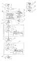
図1は、この発明の実施の形態1の車載エンジン制御装置の構成を示す回路ブロック図である。図1において、車載エンジン制御装置(以下、ECUともいう。)100Aは、車載バッテリ(以下、単にバッテリともいう。)101から電源リレー102の出力接点102aを介して給電され、電源リレー102は、電源スイッチ103が閉路したときに励磁コイル102bが付勢されて出力接点102aが閉路し、電源スイッチ103が開路して電源スイッチ信号IGSが停止すると、所定の遅延時間をおいて消勢されるようになっている。
運転状態検出センサ104aは、エンジンのクランク軸と吸排気弁の駆動用カム軸に設けられた複数の開閉センサであるクランク角センサ107a・107bを包含し、その他にエンジン回転センサ、車速センサ等の比較的高頻度に開閉動作する開閉センサ、又はアクセルペダルの踏込み度合を検出するアクセルポジションセンサ、スロットル弁開度を検出するスロットルポジションセンサ、吸気量を測定するエアフローセンサ、排気ガスの酸素濃度を測定する排気ガスセンサ、等のアナログセンサを含む第一の入力センサ群となっている。
なお、第一の入力センサ群からの入力信号は、図示しない入力インタフェース回路を介してマイクロプロセッサ(以下、CPUともいう。)120Aのデジタル入力ポートDI1とアナログ入力ポートAI1に接続されている。
1 is a circuit block diagram showing a configuration of an in-vehicle engine control apparatus according to
The operating
An input signal from the first input sensor group is connected to a digital input port DI1 and an analog input port AI1 of a microprocessor (hereinafter also referred to as CPU) 120A through an input interface circuit (not shown).
エンジン駆動機器105aは、燃料噴射用電磁弁を駆動する電磁コイル、点火プラグに高電圧を印加する点火コイル、排気循環弁の駆動用モータ、排気ガスセンサの予備加熱用電熱ヒータ等による第一の電気負荷群となっていて、マイクロプロセッサ120Aの出力ポートDO1から図示しない出力インタフェース回路を介して駆動されるようになっている。
エンジン駆動機器105aの一部である吸気弁駆動アクチェータ106aは、負荷電源リレー106bによって給電され、アクセルペダルの踏込み度合に応じたスロットル弁開度となるように帰還制御される例えば直流モータを包含し、負荷電源リレー106bが消勢されると、所
定のデフォルト位置に復帰して、固定弁開度による退避運転が行われるようになっている。
運転状態検出センサ104bは、変速機のシフトレバー位置を検出する開閉センサ、エンジンの冷却水温を検出するアナログセンサ、二重系設置されたアクセルポジションセンサ、スロットルポジションセンサ、等のアナログセンサを含み、動作頻度が低くて急速な応答性を必要としない第二の入力センサ群となっている。
なお、第二の入力センサ群からの入力信号は、図示しない入力インタフェース回路を介して監視制御回路130Aのデジタル入力ポートDI2とアナログ入力ポートAI2に接続されている。
エンジン駆動機器105bは、変速機用電磁弁或いはエアコン用電磁クラッチ等の補機を主体として、比較的低頻度の動作を行う第二の電気負荷群となっていて、監視制御回路130Aの出力ポートDO2から図示しない出力インタフェース回路を介して駆動されるようになっている。The
The intake
The driving
An input signal from the second input sensor group is connected to the digital input port DI2 and the analog input port AI2 of the
The
車載エンジン制御装置100Aは、マイクロプロセッサ120Aと、監視制御回路130Aを主体として構成されている。
電源回路110は、バッテリ101から電源リレー102の出力接点102aを介して給電され、各種の安定化された制御電源電圧Vccを生成して、マイクロプロセッサ120Aと監視制御回路130A、及びその周辺回路と入出力インタフェース回路に給電する。
駆動素子111は、電源スイッチ103が閉路されたときに励磁コイル102bを付勢すると共に、マイクロプロセッサ120Aの自己保持指令信号DR1が論理和入力されて、電源スイッチ103が一旦閉路されると自己保持指令信号DR1が停止するまでは、励磁コイル102bを付勢しておくことができるように構成されている。
補助電源112は、バッテリ101から常時給電されてRAMメモリ122の一部領域である
キープメモリに給電し、電源リレー102が消勢された状態であっても、学習記憶データ、異常履歴情報データなどの重要データの記憶保持を行なうようになっている。
電源投入検出回路113は、電源スイッチ103が閉路されて電源回路110が制御出力電圧Vccを発生したことによってイニシャルパルスIPを発生して、マイクロプロセッサ120Aを初期化・始動したり、後述の異常記憶判定回路136をリセットするようになっている。The in-vehicle
The
The driving
The
The power-on detection circuit 113 generates an initial pulse IP when the
マイクロプロセッサ120Aは、図示しない外部ツールによって制御プログラムと制御定数とが書込まれる例えば不揮発フラッシュメモリであるプログラムメモリ121Aと、演算処理用のRAMメモリ122と、多チャンネルAD変換器123を包含している。
データメモリ124Aは、シリアルポートSR1を介してマイクロプロセッサ120Aとシリアル接続された例えばEEPROMメモリである不揮発メモリであり、前記キープメモリの中で、学習するのに時間がかかる重要な学習データや、重要センサ類の経時変化特性、異常履歴情報等の貴重なデータが転送且つ保存されて、バッテリ101の異常電圧低下又はバッテリ交換時の電源断などによる貴重なデータの消失を防止するためのものとなっている。The
The data memory 124A is a non-volatile memory such as an EEPROM memory serially connected to the
監視制御回路130Aは、シリアルポートSR2を介してマイクロプロセッサ120Aとシリアル接続され、プログラムメモリ121Aから制御定数が転送される揮発性のバッファメモリ132Aと、演算回路部を包含した集積回路素子(LSI)によって構成されている。
ウォッチドッグタイマ134Aは、マイクロプロセッサ120Aが発生するウォッチドッグ信号WD1の周期が所定閾値を超過したときに、リセット出力RSTを発生してマイクロプロセッサ120Aを初期化・再起動するようになっている。The
The
論理和素子135aは、リセット信号RSTとイニシャルパルスIPと、後述の親機異常検出信号ER3とを論理和して、リセット入力信号RS1をマイクロプロセッサ120Aに供給し、論理和素子135bは、リセット信号RS1と後述の主機異常検出信号ER1と子機異常検出信号ER2を論理和して、異常記憶判定回路136に対する異常計数信号CNTを生成するようになっている。
異常記憶判定回路136は、電源投入時にイニシャルパルスIPによってリセットされ、その後異常計数信号CNTの発生回数を計数して、当該計数値が所定値を超過すると、ゲート素子137を介して負荷電源リレー106bを消勢すると共に、退避運転指令信号EMをマイクロプロセッサ120Aに供給するようになっている。
マイクロプロセッサ120Aは、シリアルポートSR2と監視制御回路130Aを介して負荷電源投入指令信号DR2を発生し、ゲート素子137を介して負荷電源リレー106bを駆動する。マイクロプロセッサ120Aはまた、後述する様々な自己診断機能を備えていて、マイクロプロセッサ120Aの制御動作に異常が発生すると、自らをリセットして初期化・再起動すると共に、主機異常検出信号ER1を発生して異常記憶判定回路136の異常計数信号CNTとなって加算計数されるようになっている。The
The abnormal
The
マイクロプロセッサ120Aは更に、監視制御回路130Aとの間のシリアル交信に異常が発生したときに子機異常検出信号ER2を発生して、異常記憶判定回路136が異常発生を加算計数すると共に、監視制御回路130Aは、子機異常検出信号ER2に基づいてリセット入力信号RS2が入力されて、バッファメモリ132Aを初期化する。
監視制御回路130Aには、運転状態検出センサの一部104bとエンジン駆動機器の一部105bが接続され、監視制御回路130Aは、マイクロプロセッサ120Aに対して入出力信号のシリアル交信を行なうと共に、マイクロプロセッサ120Aに対する質問信号を発生して、当該質問信号に対するマイクロプロセッサ120Aの回答信号が、予めプログラムメモリ121Aからバッファメモリ132Aに転送されていた正解情報と不一致であることによって親機異常検出信号ER3を発生して、マイクロプロセッサ120Aをリセットして再起動するようになっている。The
The
以上のように構成された実施の形態1の車載エンジン制御装置において、まず、図1のものの作用動作の概要を説明する。
図1において、電源スイッチ103が閉路すると、駆動素子111を介して励磁コイル102bが付勢され、電源リレー102の出力接点102aが閉路して、バッテリ101から電源端子電圧Vinが印加される。
電源回路110は各種の安定化された制御電源電圧Vccを発生して、ECU100A内の各部に給電すると共に、電源投入検出回路113がイニシャルパルスIPを発生して、異常記憶判定回路136の計数現在値をリセットし、CPU120Aには論理和素子135aを介してリセット入力信号RS1を供給する。
その結果、図2に示す初期化動作が開始され、CPU120Aが正常に始動すると、図3に示す制御動作が行われ、運転状態検出センサ104a、104bの動作状態と、プログラムメモリ121Aに格納された入出力制御プログラムに応動して、エンジン駆動機器105a・105bが駆動制御される。
CPU120Aは、後述の自己診断機能によって内部の異常点検を行なって、異常が発生すると自らをリセットして図2の初期化動作が行われ再起動されると共に、主機異常検出信号ER1を発生して異常記憶判定回路136が異常発生を計数する。In the vehicle-mounted engine control apparatus of the first embodiment configured as described above, first, an outline of the operation of the one shown in FIG. 1 will be described.
In FIG. 1, when the
The
As a result, the initialization operation shown in FIG. 2 is started, and when the
The
ウォッチドッグタイマ134Aは、CPU120Aが発生するウォッチドッグ信号WD1のパルス幅を監視して、当該パルス幅が所定値を超過すると、リセット信号RSTを発生してCPU120Aをリセットし、図2の初期化動作が行われてCPU120Aが再起動されると共に、異常記憶判定回路136が異常発生を計数する。
監視制御回路130Aは、CPU120Aの制御状態を監視して、CPU120Aからの応答が異常であるときには、親機異常検出信号ER3を発生してCPU120Aをリセットし、図2の初期化動作が行われてCPU120Aが再起動されると共に、異常記憶判定回路136が異常発生を計数する。
CPU120Aは、監視制御回路130Aの通信応答に異常があると子機異常検出信号ER2を発生して、監視制御回路130Aはバッファメモリ132Aの初期化を行い、異常記憶判定回路136が異常発生を計数する。
異常記憶判定回路136の計数記憶値が所定値を超過すると、ゲート素子137によって負荷電源リレー106bを消勢して、吸気弁駆動用アクチェータ106aが初期位置に復帰すると共に、CPU120Aに退避運転指令信号EMが入力されて、固定のスロットル弁開度によって退避運転制御を行なう。The
The
The
When the count storage value of the abnormal
次に、図1のマイクロプロセッサ120Aの初期化の動作説明用フローチャートである図2について説明する。
図2において、工程200は、後述の始動点検手段226、再起動点検手段216、定期符号点検手段310、320による自己点検で異常が検出されたとき、又はマイクロプロセッサ120Aのリセット入力信号RS1にリセット指令信号が与えられたときに、活性化される点検・初期化動作の開始ステップである。
続く工程201は、マイクロプロセッサ120Aの通信速度や割込み許可・禁止・優先順位の設定や割込み要求フラグをクリアするCPUの基本モード設定ステップである。
続く工程202は、始動点検226を行なうか再起動点検216を行なうかを選択する初期化判別手段となるステップであり、電源投入後の初回動作ではYESの判定を行なって始動点検手段226の工程203へ移行し、後述の工程209によって始動完了記憶が行なわれたことによって、次回からはNOの判定を行なって工程212へ移行するようになっている。Next, FIG. 2, which is a flowchart for explaining the initialization operation of the
In FIG. 2, a
The
The
工程203は、データメモリ124Aの内容をRAMメモリ122の空き領域に読み出して、例えばCRCチェック(巡回冗長検査)によって符号誤りの有無を点検する転送点検手段となるステップである。
続く工程204は、吸気弁駆動アクチェータ106aの給電回路が負荷電源リレー106bによって遮断可能となっているかどうか、または吸気弁駆動アクチェータ106aを制御する開閉素子が正常に動作するかどうかを点検する遮断点検手段となるステップである。
続く工程205は、RAMメモリ122の全ビットに対して1と0のそれぞれの書込みと読出しが行なえるかどうかを点検する読/書点検手段となるステップである。
続く工程206は、プログラムメモリ121Aの全領域について、例えばサム値と期待値とが一致するかどうかのサムチェックによって符号誤りの有無を点検する符号点検手段となるステップであり、工程203から工程206によって構成された工程ブロック226は始動点検手段となっている。Step 203 is a step serving as a transfer check means for reading the contents of the data memory 124A into an empty area of the
The
The subsequent step 205 is a step which becomes a read / write check means for checking whether or not writing and reading of 1 and 0 can be performed on all bits of the
工程207は、工程ブロック226において、全ての点検テストが正常であったかどうかを
判定し、正常であればYESの判定を行なって工程ブロック208へ移行するが、何らかの異常があればNOの判定を行なって工程220へ移行する異常有無の判定ステップである。
工程ブロック208は、RAMメモリ122の初期設定を行う初期化手段となるステップであり、バッテリ101が接続されて以来、最も最初に電源スイッチ103が投入されて工程ブロック208に到来した場合であれば、工程ブロック208においてRAMメモリ122の全領域に対する初期設定が行われる。
初期設定の第一の内容は、製品出荷段階で予めプログラムメモリ121Aからデータメモリ124Aへ転送されていた最重要データのデフォルト値であって、データメモリ124AからRAMメモリ122の第一領域に転送され、第二の内容は、RAMメモリ122内にあってバッテリバックアップされたキープメモリに格納される重要データのデフォルト値であって、プログラムメモリ121AからRAMメモリ122の第二領域に転送され、第三の内容は、現在データを消去しておくためのクリアデータであって、通常はRAMメモリ122の第三領域に対してデータゼロが転送されるようになっている。
なお、上記の第一の内容は、後述の工程302(図3参照)によって最重要データを基にした学習補正データとしてデータメモリ124Aに対して更新書込みされることになり、一旦
データメモリ124Aに転送且つ保存された後の工程ブロック208における初期化においては、第一の内容はデータメモリ124Aから読出しされた更新データとなり、第二の内容は変更しないで現状データを維持し、第三の内容は消去されるようになっている。
また、RAMメモリ122内に格納される最重要データや重要データは、正論理データと反転論理データの一対のデータとなっていて、後述の定期点検では反転論理照合を行なって異常の有無が判定され、初期化に当たっては異常発生アドレスのデータのみが書換えされるようになっている。In
The
The first initial setting is the default value of the most important data that was previously transferred from the
Note that the above first content is updated and written to the data memory 124A as learning correction data based on the most important data in a later-described step 302 (see FIG. 3), and once stored in the data memory 124A. In the initialization in the process block 208 after being transferred and stored, the first content is the update data read from the data memory 124A, the second content is not changed, the current data is maintained, and the third content Is to be erased.
The most important data and important data stored in the
続く工程209では、工程ブロック226による始動点検を無事通過したことに伴って始動完了状態が記憶されるようになっている。
なお、この始動完了記憶は、電源スイッチ103が開路されて再度投入されたときにリセットされるようになっているので、電源投入直後は必ず工程202はYESの判定を行なって、始動点検226とこれに伴う初期化設定208が実行されることになる。
始動点検に異常があったときに実行される工程220では、主機異常検出信号ER1を発生し、続く工程221では、異常記憶判定回路136から退避運転指令信号EMが入力されたかどうかを判定し、退避運転指令信号EMが入力されておれば、YESの判定を行なって退避運転手段となる工程ブロック222へ移行し、退避運転指令信号EMが入力されていなければ、NOの判定を行なって工程201へ復帰移行するようになっている。
従って、車載エンジン制御装置100Aに何らかのハードウエア異常があって始動点検手段226が異常検出した場合であれば、何度始動点検を行なってもいつも異常検出されることになり、工程201、202〜207、220、221を循環する都度に、工程220で主機異常検出信号ER1が発生することによって異常記憶判定回路136がカウントアップし、退避運転指令信号EMが発生することによって退避運転モードへ移行することになる。In the
The start completion memory is reset when the
In
Therefore, if there is some hardware abnormality in the in-vehicle
始動点検を正常通過して工程209によって始動完了が記憶されると、続く工程210では非同期燃料噴射を行なう必要があるかどうかの判定が行なわれ、不要であればNOの判定を行なって、動作終了工程230へ移行して初期化を完了し、必要であればYESの判定を行なって、工程ブロック211aへ移行してから動作終了工程230へ移行して初期化を完了するようになっている。
なお、要否判定手段となる工程210では、エンジンの始動用スイッチが投入されているか、
エンジンが自立回転できない低回転であって、バッテリ101の出力電圧が異常低下しているか、低電圧・低温環境での始動電動機の駆動を必要とする場合にYESの判定を行なうようになっており、工程211aの非同期燃料噴射制御については図4で詳細に説明する。
このようにして点検・初期化が完了すると、図3で後述する入出力制御動作が開始されて定常運転状態となるが、この定常運転中で実施される定期符号点検手段310、320で異常が検出されると、再び図2の工程200へ移行し点検・初期化動作が開始される。When the start-up inspection is normally passed and the completion of the start-up is memorized in
In
YES is determined when the engine is running at a low speed that cannot rotate independently and the output voltage of the
When the inspection / initialization is completed in this way, an input / output control operation, which will be described later with reference to FIG. 3, is started to enter a steady operation state. However, there is an abnormality in the periodic code inspection means 310, 320 performed during the steady operation. If detected, the process again proceeds to step 200 in FIG. 2 to start the inspection / initialization operation.
工程212は、図3の工程314によって、プログラムメモリ121Aの異常フラグ#nがセットされているかどうかを判定するステップであり、異常フラグがセットされていると、YESの判定を行なって工程213へ移行し、プログラムメモリ121Aの異常フラグがセットされていなければ、NOの判定を行なって工程214へ移行する。
工程213は、プログラムメモリ121Aの分割ブロック#nについて、例えばサム値と期待値とが一致するかどうかのサムチェックによって符号誤りの有無を点検してから工程215へ移行する符号点検手段となるステップである。
工程214は、図3の工程324によって、RAMメモリ122の異常フラグがセットされているかどうかを判定するステップであり、異常フラグがセットされていると、YESの判定を行なって工程215へ移行し、RAMメモリ122の異常フラグがセットされていなければ
NOの判定を行なって工程217へ移行する。Step 212 is a step of determining whether or not the abnormality flag #n of the
Step 213 is a step that becomes a code check means for checking the presence or absence of a code error for the divided block #n of the
Step 214 is a step for determining whether or not the abnormality flag of the
A determination of NO is made and the process proceeds to step 217.
工程215は、RAMメモリ122の異常発生アドレスのビットに対して1と0のそれぞれの書込みと読出しが行なえるかどうかの点検を行なってから工程217へ移行する読/書点検手段となるステップである。
なお、後述の工程320で行なわれるRAMメモリ122の定期点検は、例えば反転データとの照合による特定重要データの個別符号点検であるのに対し、工程215で行なわれるRAMメモリ122の点検は、ハードウエア異常の有無を点検するものとなっている。
また、工程213と工程215によって構成された工程ブロック216は、再起動点検手段となるものである。Step 215 is a step which becomes a reading / writing check means for checking whether or not writing and reading of 1 and 0 can be performed for each bit of the error occurrence address in the
The periodic inspection of the
In addition, the process block 216 configured by the
工程217は、工程ブロック216において、全ての点検テストが正常であったかどうかを判定し、正常であればYESの判定を行なって工程ブロック218へ移行するが、何らかの異常があれば、NOの判定を行なって工程220へ移行する異常有無の判定ステップである。
工程ブロック218は、RAMメモリ122の初期設定を行う初期化手段となるステップであり、再起動点検後の初期化手段である工程ブロック218では、定期点検によって検出された異常発生アドレスのデータについて、データメモリ124Aから読出し設定するか、プログラムメモリ121Aのデフォルト値を読出し設定するようになっている。
続く工程219は、図3の工程313又は工程324でセットされた異常フラグをリセットするステップである。
続く工程ブロック211bは、図4で後述する非同期燃料噴射制御手段となるものであり、非同期燃料噴射を行なってから動作終了工程230へ移行して初期化を完了し、図3の制御動作開始工程300へ移行するようになっている。Step 217 determines whether or not all inspection tests are normal in the
The
The
以上の動作の概要を説明すると、運転開始時には始動点検手段226によって詳しく車載エンジン制御装置100Aの状態点検が行なわれる。
この始動点検時では、電源スイッチ103が閉路されてからエンジン始動スイッチが閉路されるまでの躊躇(ためらい)時間と、始動スイッチが閉路されてから燃料噴射制御と点火制御が可能となる最低限度のエンジン回転速度に達するまでの初動時間とがあって、これらの猶予時間の間に始動点検を完了すればよい。
これに対し、運転中の偶発的な異常発生に伴う再起動点検手段216では、再起動後に燃料噴射と点火制御を再開すれば始動電動機によらないでエンジン回転が持続できることが望ましく、理想的には運転手に違和感を与えないで継続運転されることが求められる。
従って、再起動点検手段では、定期点検における異常発生原因に基づいて、焦点を絞った点検を行なうことが肝要であり、始動点検手段226と同じ内容の点検を行なわないようになっている。
また、たとえノイズ誤動作等による偶発的な異常発生であったとしても、異常発生回数が所定値を超過すると退避運転モードに移行して安全性を損なわないようになっている。The outline of the above operation will be described. When the operation is started, the state check of the in-vehicle
At the time of this start inspection, the hesitation time from when the
On the other hand, it is desirable that the restart check means 216 due to an accidental abnormality during operation should continue the engine rotation without relying on the starting motor if fuel injection and ignition control are restarted after restart. Is required to continue driving without causing the driver to feel uncomfortable.
Therefore, it is important for the restart inspection means to perform a focused inspection based on the cause of the abnormality in the periodic inspection, and the same inspection content as the start inspection means 226 is not performed.
Further, even if an accidental abnormality occurs due to a noise malfunction or the like, when the abnormality occurrence number exceeds a predetermined value, the operation mode is shifted to the evacuation operation mode so that safety is not impaired.
次に、図1のマイクロプロセッサ120Aの運転中の動作説明用フローチャートである図3について説明する。
図3において、工程300は、初期化完了工程230に続いて実行される入出力制御の動作開始ステップ、続く工程301は、電源スイッチ103が閉路されているかどうかを判定し、閉路されておれば、YESの判定を行なって工程ブロック306へ移行し、閉路されていたものが開路されていたときには、NOの判定を行なって工程302へ移行する判定ステップとなっている。
入出力制御手段となる工程ブロック306は、エンジンのクランク軸と吸排気弁の駆動用カ
ム軸に設けられた複数の開閉センサであるクランク角センサ107a、107bに基づいて、順
次燃料噴射と点火制御を行なう気筒判別手段306a、燃料噴射制御手段306b、点火コイル
制御手段306cと、アクセルペダルの踏込み度合に応動して吸気用スロットル弁の弁開度
を制御する弁開度制御手段306dによって構成されている。
なお、燃料噴射制御手段306bでは、排気ガスセンサによって空燃比を所定値に維持する負帰還制御が行なわれ、点火コイル制御手段306cでは、エンジンの振動を測定するノックセンサによる点火時期の負帰還制御が行われるようになっている。Next, FIG. 3, which is a flowchart for explaining operations during the operation of the
In FIG. 3, a
A
The fuel injection control means 306b performs negative feedback control that maintains the air-fuel ratio at a predetermined value by an exhaust gas sensor. The ignition coil control means 306c performs negative feedback control of ignition timing by a knock sensor that measures engine vibration. To be done.
続く工程307aは、プログラムメモリ121Aの点検時期であるかどうかを判定し、点検時期であればYESの判定を行なって工程311へ移行し、点検時期でなければNOの判定を行なって工程307bへ移行する判定ステップとなっている。
工程311は、プログラムメモリ121Aの分割ブロック#nについて、例えばサム値と期待値とが一致するかどうかのサムチェックによって符号誤りの有無を点検してから工程312へ移行する符号点検手段となるステップであり、工程311が実行される度に点検ブロック番号が循環更新設定されるようになっている。
工程312は、工程311によって異常が検出されたかどうかを判定し、異常検出された場合には、YESの判定を行なって工程313へ移行し、異常が検出されなかったときには、NOの判定を行なって工程307bへ移行するようになっている。
工程313では、異常フラグ#nをセットして異常検出信号ER1を発生し、続く工程314では、マイクロプロセッサ120Aをリセットして、図2の工程200へ移行する。
なお、工程313でセットされた異常フラグ#nは、図2の工程219でリセットされるようになっている。In the
Step 311 is a step that becomes a code check means for checking the presence / absence of a code error for the divided block #n of the
Step 312 determines whether or not an abnormality is detected in
In
Note that the abnormality flag #n set in
工程307bは、RAMメモリ122の点検時期であるかどうかを判定し、点検時期であればYESの判定を行なって工程321へ移行し、点検時期でなければNOの判定を行なって動作終了工程330へ移行する判定ステップとなっている。
工程321は、RAMメモリ122の最重要データと重要データについて、例えば反転論理照合によって符号誤りの有無を点検してから工程322へ移行する符号点検手段となるステップであり、工程322による異常点検では、異常発生したRAMメモリ122のアドレスが特定されるようになっている。
工程322は、工程321によって異常が検出されたかどうかを判定し、異常検出された場合にはYESの判定を行なって工程323へ移行し、異常が検出されなかったときにはNOの判定を行なって動作終了工程330へ移行する。
工程323では、RAM異常フラグをセットして異常検出信号ER1を発生し、続く工程324では、マイクロプロセッサ120Aをリセットして、図2の工程200へ移行する。
なお、工程323でセットされたRAM異常フラグは、図2の工程219でリセットされるようになっている。In
Step 321 is a step that serves as a code check means for checking the presence or absence of a sign error for the most important data and important data in the
Step 322 determines whether an abnormality is detected in
In
Note that the RAM abnormality flag set in
動作終了工程330では、他の制御動作を行って、例えば10msec以内の所定時間後には再度動作開始工程300へ循環移行するようになっている。
工程311から工程314で構成された工程ブロック310と、工程321から工程324で構成された工程ブロック320は、それぞれプログラムメモリ121AとRAMメモリ122に関する定期符号点検手段となるものであり、各定期符号点検手段310、320は、工程300から工程330に至る一連の入出力制御の複数回の循環動作によって一回分の定期点検が完了し、例えば100msecに一回の定期点検結果が得られるように分散動作するようになっている。In the
The
電源スイッチ103が開路された後に実行される工程302では、RAMメモリ122の転送保存領域に格納されていた最重要データが、運転中の学習補正によって補正され、最新学習データとしてデータメモリ124Aへ転送保存される。
続く工程303は、RAMメモリ122のキープメモリ領域である第二領域の特定アドレスにあるメモリRAMaに特定データYYを書込んでおくステップであり、若しもバッテリ101の電源端子が開路されたような場合に、特定データYYの内容が変化することによってこれを検知するためのものとなっている。
続く工程304では、自己保持指令信号DR1を停止してマイクロプロセッサ120Aをリセットするが、その結果として電源リレー102が消勢されて車載エンジン制御装置100Aの動作が停止する。In
The
In the
次に、実施の形態1の車載エンジン制御装置における非同期燃料噴射制御の動作説明用フローチャートである図4について説明する。
図4において、工程400は、図2の工程ブロック211a、211bで示された非同期燃料噴射制御手段の動作開始ステップである。
続く工程401は、クランク角センサ107a、107bのうち、クランク軸に設けられたクランク角センサ107aが基準点位置を通過したかどうかを判定し、基準点を通過したら工程ブロック402へ移行する判定ステップであり、当該基準点は例えばクランク軸に設けられて外周に10度刻みの歯が設けられている回転円盤と対向するクランク角センサ107aが、当該回転円盤に設けられた欠歯部分を検出することによって基準点通過を検出するようになっている。
行程ブロック402は、後述の行程403、404、405を循環しながら、クランク軸の回転に応動するクランク角センサ107aと、吸気弁用カム軸の回転に応動するクランク角センサ107bの動作状態を監視して気筒群を判別し、各気筒に対する燃料噴射タイミングや点火タイミングを決定するための弁別制御を行なう気筒判別手段となっている。
なお、当該気筒判別手段は、気筒判別を開始してからエンジンが最大で2回転するまでに全気筒の判別を完了するが、気筒群の判別は、全気筒の判別よりも早いタイミングで完了するようになっている。Next, FIG. 4 which is a flowchart for explaining the operation of the asynchronous fuel injection control in the in-vehicle engine control apparatus of the first embodiment will be described.
In FIG. 4, a
A
The
The cylinder discrimination means completes the discrimination of all cylinders from the start of cylinder discrimination until the engine makes two revolutions at the maximum, but the discrimination of cylinder groups is completed at a timing earlier than the discrimination of all cylinders. It is like that.
続く工程403は、行程ブロック402が気筒群の判別を完了したかどうかを判定して、判定未完了であればNOの判定を行なって工程404へ移行し、判定完了であればYESの判定を行なって行程407へ移行する判定ステップとなっている。
行程404は、応急噴射を行なう必要があるかどうかを判定して、応急噴射が必要であれば
YESの判定を行なって工程406へ移行し、応急噴射が不要であればNOの判定を行なって工程405へ移行する応急噴射判定手段となるステップである。
なお、再起動点検手段216に続いて実行される非同期燃料噴射制御手段211bにおける応急噴射判定手段404は、再起動点検手段216においてプログラムメモリ121Aに関するメモリ点検が行なわれたときに、応急噴射必要の判定を行ない、再起動点検手段216においてRAMメモリ122に関するメモリ点検のみが行なわれたときには、応急噴射不要の判定を行なうようになっている。
また、始動点検手段226に続いて実行される非同期燃料噴射制御手段211aにおける応急射判定手段404は、環境温度と車載バッテリ電圧が所定の劣悪条件にあるときに応急噴射必要の判定を行い、環境温度と車載バッテリ電圧が劣悪とは言えない所定の好条件にあるときには応急噴射不要の判定を行なうようになっている。In the
In
In this step, the process proceeds to step 406 by making a determination of YES, and if the emergency injection is unnecessary, the step becomes an emergency injection determination means that makes a determination of NO and proceeds to process 405.
The emergency injection determination means 404 in the asynchronous fuel injection control means 211b, which is executed following the restart inspection means 216, requires the emergency injection when the memory inspection related to the
Further, the emergency firing determination means 404 in the asynchronous fuel injection control means 211a, which is executed following the start inspection means 226, determines whether the emergency injection is necessary when the environmental temperature and the in-vehicle battery voltage are in a predetermined inferior condition. When the temperature and the in-vehicle battery voltage are in a predetermined favorable condition that cannot be said to be inferior, it is determined that the emergency injection is unnecessary.
行程405は、クランク角センサ107a、107bのどちらかが動作したかどうかを判定し、不動作であればNOの判定を行なって工程405に復帰し、動作すればYESの判定を行って工程402へ循環復帰する判定ステップとなっている。
行程406は、図5(C)で後述する第一の非同期噴射を行なう第一の非同期燃料噴射制御手段となるステップである。
工程407は、行程ブロック402が全気筒の判別を完了したかどうかを判定して、判定未完了であればNOの判定を行なって工程408へ移行し、判定完了であればYESの判定を行なって動作終了行程410へ移行する判定ステップとなっている。
行程408は、図5(B)で後述する第二の非同期噴射を行なう第二の非同期燃料噴射制御手段となるステップである。
行程406又は行程408に続いて動作終了行程410へ移行し、図2の動作終了行程230と図3の動作開始工程300を経て、燃料噴射制御手段306bで示した同期噴射が行なわれるようになっている。In
Step 406 is a step serving as a first asynchronous fuel injection control means for performing a first asynchronous injection described later with reference to FIG.
In
Step 408 is a step serving as a second asynchronous fuel injection control means for performing second asynchronous injection described later with reference to FIG.
After the
次に、図1の車載エンジン制御装置において、筒外噴射エンジンが使用されている場合の動作行程図である図5について説明する。
なお、ここで言う筒外噴射とは、排気行程で噴射された燃料がエンジンのシリンダ外の吸気管に滞留し、エンジンの筒壁吸気弁が開くことによってシリンダ内に吸引されるものである。
図5(A)は、正常な同期噴射が行なわれている場合の燃料噴射タイミングIと、点火タイミングIGを示したものである。
燃料噴射Iは各気筒の排気行程で行なわれ、点火IGは圧縮行程で行なわれるようになっているが、以下では燃料噴射と燃焼動作に注目して説明する。
気筒1の吸気行程で気筒判別が開始すると、この時点で圧縮行程にあった気筒2の排気行程で気筒判別が完了して初回の燃料噴射52bが行なわれ、気筒2の燃焼行程で初爆55が
行なわれ、以降は気筒1、気筒3、気筒4の順で有効な燃焼行程56、57、58を迎えるこ
とになる。Next, FIG. 5, which is an operation stroke diagram when an out-of-cylinder injection engine is used in the in-vehicle engine control apparatus of FIG. 1, will be described.
The term “in-cylinder injection” as used herein means that fuel injected in the exhaust stroke stays in the intake pipe outside the cylinder of the engine and is sucked into the cylinder by opening the cylinder wall intake valve of the engine.
FIG. 5A shows the fuel injection timing I and the ignition timing IG when normal synchronous injection is performed.
The fuel injection I is performed in the exhaust stroke of each cylinder, and the ignition IG is performed in the compression stroke. The following description will focus on the fuel injection and the combustion operation.
When the cylinder discrimination is started in the intake stroke of the
図5(B)は、第二の非同期燃料噴射制御手段408によって気筒群別同時噴射が行なわれる場合であり、気筒4の排気行程で燃料噴射51dが行なわれると共に、気筒1の圧縮行程で非同期同時噴射51aが行なわれている。
但し、この時点ではどちらの気筒が排気行程で、どちらの気筒が圧縮行程であるかは判別されておらず、どちらか一方が排気行程であることだけが判別されている。
その結果、気筒4の燃料噴射51dに基づいて初爆54が発生し、図5(A)に比べて1行程だけ早い時期に初爆が行なわれることになる。
但し、気筒1では、同時燃料噴射51aと排気行程における燃料噴射53aの2回分の燃料噴射によって燃焼行程56で燃焼が行なわれるので、過剰燃料となって排気ガス成分が悪化するのを我慢する必要がある。
なお、燃料噴射53aを休止することも可能であるが、この場合には燃焼行程56における
燃焼では希薄燃料となって、排気ガス成分が悪化することになる。FIG. 5B shows a case where the second asynchronous fuel injection control means 408 performs simultaneous injection by cylinder group, and fuel injection 51d is performed in the exhaust stroke of the
However, at this time, it is not determined which cylinder is in the exhaust stroke and which cylinder is in the compression stroke, and only one of the cylinders is in the exhaust stroke.
As a result, the
However, in the
The
図5(C)は、第一の非同期燃料噴射制御手段406によって全気筒の同時噴射が行なわれる場合であり、気筒4の排気行程で燃料噴射51dが行なわれると共に、気筒1の圧縮行程で非同期同時噴射51aが行なわれ、気筒2の燃焼行程で燃料噴射51bが行なわれ、気筒3の吸気行程で燃料噴射51cが行なわれている。
但し、この時点では各気筒の現在行程は全く判別されておらず、気筒4が偶然に排気行程であったことになるものである。
その結果、気筒3の燃料噴射51cに基づいて初爆53が発生し、図5(B)に比べて更に1行程だけ早い時期に初爆が行なわれることになる。
但し、気筒1では、同時燃料噴射51aと排気行程における燃料噴射53aの2回分の燃料噴射によって燃焼行程56で燃焼が行なわれ、気筒2では、同時燃料噴射51bと排気行程における燃料噴射52bの2回分の燃料噴射によって燃焼行程55で燃焼が行なわれるので、過剰燃料となって排気ガス成分が更に悪化するのを我慢する必要がある。FIG. 5C shows a case where all the cylinders are simultaneously injected by the first asynchronous fuel injection control means 406. The fuel injection 51d is performed in the exhaust stroke of the
However, at this point, the current stroke of each cylinder has not been determined at all, and the
As a result, an
However, in the
次に、図1の車載エンジン制御装置において、筒内噴射エンジンが使用されている場合の動作行程図である図6について説明する。
なお、ここで言う筒内噴射とは、吸気行程においてエンジンのシリンダ内に燃料を直接噴射注入し、吸気弁からは大気のみが吸入されるものである。
図6(A)は、正常な同期噴射が行なわれている場合の燃料噴射タイミングIと点火タイミングIGを示したものである。
燃料噴射Iは各気筒の吸気行程で行なわれ、点火IGは圧縮行程で行なわれるようになっているが、以下では燃料噴射と燃焼動作に注目して説明する。
気筒1の吸気行程で気筒判別が開始されると、この時点で燃焼行程にあった気筒4の吸気行程で気筒判別が完了して初回の燃料噴射62dが行なわれ、気筒4の燃焼行程で初爆64が行なわれ、以降は気筒2、気筒1、気筒3、気筒4の順で有効な燃焼行程65、66、67、
68を迎えることになる。Next, FIG. 6, which is an operation stroke diagram when the in-cylinder injection engine is used in the in-vehicle engine control device of FIG. 1, will be described.
The in-cylinder injection referred to here is that in which fuel is directly injected and injected into the cylinder of the engine in the intake stroke, and only the atmosphere is sucked from the intake valve.
FIG. 6A shows the fuel injection timing I and the ignition timing IG when normal synchronous injection is performed.
The fuel injection I is performed in the intake stroke of each cylinder, and the ignition IG is performed in the compression stroke. The following description will focus on the fuel injection and the combustion operation.
When the cylinder discrimination is started in the intake stroke of the
68 will be greeted.
図6(B)は、第二の非同期燃料噴射制御手段408によって気筒群別同時噴射が行なわれる場合であり、気筒3の吸気行程で燃料噴射61cが行なわれると共に、気筒2の燃焼行程で非同期同時噴射61bが行なわれている。
但し、この時点ではどちらの気筒が吸気行程で、どちらの気筒が燃焼行程であるかは判別されておらず、どちらか一方が吸気行程であることだけが判別されている。
その結果、気筒3の燃料噴射61cに基づいて初爆63が発生し、図6(A)に比べて1行程だけ早い時期に初爆が行なわれることになる。
但し、気筒2では、同時燃料噴射61bと吸気行程における燃料噴射63bの2回分の燃料噴射によって燃焼行程65で燃焼が行なわれ、燃焼行程における燃料噴射61bは、点火が行なわれていないので未燃焼のままで続く排気行程で排気されることになる。
なお、筒内噴射の場合には、筒外噴射に比べて燃料噴射から点火までの期間が1行程分短縮されているので、初爆タイミングも1行程だけ早くなっている。
しかし、全気筒一斉の同時噴射を行なっても、有効となるのはどれかの1気筒だけであって、初爆タイミングを早めることはできず、いたずらに生ガスの排気を増やすだけのこととなって効果がない。FIG. 6B shows a case where the second asynchronous fuel injection control means 408 performs the cylinder group simultaneous injection. The fuel injection 61c is performed in the intake stroke of the cylinder 3, and the combustion stroke of the cylinder 2 is asynchronous. Simultaneous injection 61b is performed.
However, at this time, it is not determined which cylinder is in the intake stroke and which cylinder is in the combustion stroke, and only one of the cylinders is in the intake stroke.
As a result, the
However, in the cylinder 2, combustion is performed in the
In the case of in-cylinder injection, the period from fuel injection to ignition is shortened by one stroke compared to the in-cylinder injection, so the initial explosion timing is also advanced by one stroke.
However, even if simultaneous injection is performed for all cylinders at the same time, only one of the cylinders is effective, and the timing of the first explosion cannot be advanced. It has no effect.
実施の形態1の要点と特徴
以上の説明で明らかな通り、この発明の実施の形態1による車載エンジン制御装置は、多気筒車載エンジンの運転状態検出センサ104a、104bの動作状態に応動してエンジン駆動機器105a、105bを制御するマイクロプロセッサ120Aと、このマイクロプロセッサと協働し、クランク角センサ107a、107bの動作状態に同期して燃料噴射弁を順次開弁駆動する燃料噴射制御手段306bと、異常発生時にマイクロプロセッサを初期化・再起動する自己診断手段とを包含した不揮発性のプログラムメモリ121Aと、車載バッテリ101から常時給電されて、一部領域が電源スイッチ103の遮断状態においても記憶状態を保持するキープメモリとして使用されるRAMメモリ122と、電源スイッチ103が開路された後の遅延給電期間においてRAMメモリ122の特定領域に格納された重要データが転送且つ保存される不揮発性のデータメモリ124Aとを備えた車載エンジン制御装置100Aであって、
プログラムメモリ121Aは更に、初期化判別手段202によって選択される始動点検手段226又は再起動点検手段216を経て、RAMメモリ122に対して所定のデフォルト値を書込み設定する初期化手段208・218となる制御プログラムを包含している。
初期化判別手段202は、エンジン始動時に実行される始動点検手段226を実行するのか、又は運転中においてマイクロプロセッサ120Aに異常が発生したことに伴う再起動点検手段216を実行するのかを判別する手段である。Main Points and Features of
The
Initialization determination means 202 determines whether to execute start check means 226 that is executed when the engine is started, or whether to execute restart check means 216 that accompanies an abnormality in
また、始動点検手段226は、データメモリ124Aの内容をRAMメモリ122に転送して当該転送データのビット情報の混入・欠落の有無を検出する転送点検手段203と、プログラムメモリ121Aのビット情報の混入・欠落の有無を検出する符号点検手段206と、RAMメモリ122の読み書きが正常に行なわれるかどうかの読/書点検手段205と、吸気弁駆動用アクチェータ106aの給電回路の遮断点検手段204とによる自己診断手段の中の複数手段によって構成されている。
再起動点検手段216は、プログラムメモリ121Aのビット情報の混入・欠落の有無を検出する符号点検手段213と、RAMメモリ122の読み書きが正常に行なわれるかどうかの読/書点検手段215との少なくとも一方の手段を含み、始動点検手段226に比べて簡略化された自己診断項目によって構成されたメモリ点検手段である。
前記自己診断手段は更に、プログラムメモ121AとRAMメモリ122の一部領域に関し、マイクロプロセッサ120Aの運転中において略定期的に実行されてビット情報の混入・欠落の発生を検出すると、マイクロプロセッサ120Aをリセットして初期化・再起動すると共に、プログラムメモリ121Aの異常又はRAMメモリ122の異常の異常発生フラグをセットする定期符号点検手段310、320を備え、再起動点検手段216において実行されるメモリ点検手段は、前記異常発生フラグの種別に対応したメモリの点検を行なうものとなっている。Further, the start check means 226 transfers the contents of the data memory 124A to the
The restart check means 216 includes at least a sign check means 213 for detecting the presence / absence of bit information in the
The self-diagnostic means further executes the
プログラムメモリ121Aは更に、吸気弁駆動アクチェータ106aに対する弁開度制御手段306dと、当該弁開度制御手段を停止した状態でエンジンを駆動制御する退避運転手段222となる制御プログラムを包含すると共に、マイクロプロセッサ120Aには、外部診断回路130A、134Aと異常記憶判定回路136とが付加されている。
前記外部診断回路は、マイクロプロセッサ120Aが発生するウォッチドッグ信号WD1の周期が所定閾値を超過したときに、リセット出力RSTを発生してマイクロプロセッサ120Aを初期化・再起動するウォッチドッグタイマ134Aであるか、またはマイクロプロセッサ120Aの制御動作を監視して、異常検出時に親機異常検出信号ER3を発生してマイクロプロセッサ120Aを初期化・再起動する監視制御回路130Aの少なくとも一方によって構成される。
異常記憶判定回路136は、外部診断回路130A、134Aによってマイクロプロセッサ120Aに入力されたリセット信号RS1と、自己診断手段が発生する主機異常検出信号ER1の発生回数を計数し、当該計数値が所定閾値を超過したときに、吸気弁駆動アクチェータ106aの電源を遮断して、退避運転手段222を有効にするカウンタ回路であって、当該カウンタ回路の計数現在値は、電源スイッチ103の投入時に発生するイニシャルパルスIPによってリセットされると共に、マイクロプロセッサ120AはイニシャルパルスIPによって初期化されて始動するものである。The
The external diagnostic circuit is a
The abnormal
以上のように構成されたこの発明の実施の形態1の車載エンジン制御装置によれば、運転中のマイクロプロセッサは自己診断手段である定期符号点検手段に加えて、外部診断回路によっても常時異常点検されており、異常発生の原因がノイズ誤動作による偶発的なものであれば速やかにマイクロプロセッサの初期化・再起動によって運転を続行し、異常発生回数が所定回数を超過すると吸気弁開度をデフォルト開度に固定した退避運転が行われるようになっている。
従って、異常点検が自己診断と外部診断によって分担されているので、マイクロプロセッ
サの再起動点検時間が短縮され、異常発生の原因がノイズ誤動作による偶発的なもので
あって回復可能な場合には、エンジン停止期間を短縮して速やかに継続運転状態に移行す
ることができる特徴がある。According to the in-vehicle engine control apparatus of the first embodiment of the present invention configured as described above, the operating microprocessor is always checked for abnormalities by an external diagnostic circuit in addition to the periodic code checking means which is a self-diagnosis means. If the cause of the abnormality is accidental due to a noise malfunction, the operation is immediately continued by initializing / restarting the microprocessor, and the intake valve opening is defaulted when the number of occurrences exceeds the specified number. The evacuation operation fixed at the opening is performed.
Therefore, since the abnormality check is shared by self-diagnosis and external diagnosis, the time required for restarting the microprocessor is shortened, and if the cause of the abnormality is accidental due to noise malfunction and can be recovered, There is a feature that the engine stop period can be shortened and the operation can be promptly shifted to the continuous operation state.
また、実施の形態1において、プログラムメモリ121Aは更に、非同期燃料噴射制御手段となる制御プログラムを包含している。
当該非同期燃料噴射制御手段は、少なくとも再起動点検による初期化が完了し、クランク角センサに基づく気筒判別が完了して各気筒に対して順次クランク角センサの動作と連動同期した燃料噴射制御306bが行われる前段階において、複数気筒に対して先行同時噴射を行なってマイクロプロセッサ120Aがリセットされてエンジンが再駆動されるまでの時間を短縮する手段である。
当該非同期燃料噴射制御手段は、クランク角センサ107a・107bの動作と連動して全気筒に対して一斉同時噴射を行なう第一の非同期燃料噴射制御手段406であるか、又は少なく
とも噴射タイミングが2行程異なる気筒によって構成された気筒群の判別が行なわれた後
で、燃料噴射を行うべき気筒を包含した気筒群に対してのみ群別一斉同時噴射を行なう第
二の非同期燃料噴射制御手段408の少なくとも一方が適用されるものである。In the first embodiment, the
In the asynchronous fuel injection control means, at least initialization by restart inspection is completed, cylinder discrimination based on the crank angle sensor is completed, and fuel injection control 306b synchronized with the operation of the crank angle sensor sequentially for each cylinder is provided. This is a means for shortening the time from when the simultaneous injection is performed to a plurality of cylinders to reset the
The asynchronous fuel injection control means is the first asynchronous fuel injection control means 406 that performs simultaneous simultaneous injection to all the cylinders in conjunction with the operation of the
このように実施の形態1の車載エンジン制御装置は、再起動点検による初期化の後に、第一又は第二の非同期燃料噴射制御手段によって、全気筒一斉又は気筒群別の一斉先行噴射が行なわれるようになっている。
従って、例えば運転中のノイズ誤動作によってマイクロプロセッサがリセットされたこと
に伴うエンジン駆動停止時間を更に短縮することができる特徴がある。
なお、エンジンの始動性を改善させるための非同期燃料噴射制御手段はエンジン回転速度
が低く、環境温度が低く、車載バッテリ電圧が低いときに適用されるものであるが、再起
動点検後に実施される非同期燃料噴射制御手段は、エンジン回転速度が高く、環境温度や車載バッテリ電圧が適正であるにも関わらず適用されて、運転中のエンジン瞬停に対する再初爆期間を早めるものとなっている。
また、第一の非同期燃料噴射制御手段によれば、排気ガスの状態が一時的に悪化するが、最も速やかにエンジンの再起動が行なわれ、第二の非同期燃料噴射制御手段によれば、排気ガスの状態が一時的に若干悪化するが、比較的速やかにエンジンの再起動が行なわれる特徴がある。As described above, in the in-vehicle engine control apparatus according to the first embodiment, after the initialization by the restart inspection, the first or second asynchronous fuel injection control means performs simultaneous advance injection for all cylinders or for each cylinder group. It is like that.
Therefore, for example, the engine drive stop time associated with the reset of the microprocessor due to a noise malfunction during operation can be further shortened.
The asynchronous fuel injection control means for improving the engine startability is applied when the engine speed is low, the environmental temperature is low, and the vehicle battery voltage is low. Asynchronous fuel injection control means is applied in spite of high engine rotation speed and appropriate environmental temperature and in-vehicle battery voltage, and accelerates the re-initial explosion period for engine instantaneous power failure during operation.
Further, according to the first asynchronous fuel injection control means, the state of the exhaust gas temporarily deteriorates, but the engine is restarted most quickly, and according to the second asynchronous fuel injection control means, the exhaust gas is exhausted. Although the gas state temporarily deteriorates slightly, the engine is restarted relatively quickly.
また、実施の形態1の車載エンジン制御装置において、初期化判別手段202は、初回フラグFLGの論理状態によって判定され、当該初回フラグFLGは、始動点検手段226が実行されたことによってフラグ設定手段209によってセットされ、電源スイッチ103の投入時にリセットされるものである。
初回フラグFLGがセットされていないときには始動点検手段226が実行され、初回フラグFLGがセットされているときには再起動点検手段216が実行されるものである。
このように、初期化判別手段202は、電源投入時にリセットされ、始動点検後にセットされる初回フラグの動作状態によって、始動点検と再起動点検を選択するようになっていて、運転中に瞬時停電が発生した場合にあっては、初回フラグがリセットされて始動点検が行なわれることになる。
従って、簡易な手段によって初期化判別が行なえると共に、運転中に瞬時停電が発生した
場合にあっては、運転中の定期符合点検手段に依存することがない始動点検を行なうことができる特徴がある。In the in-vehicle engine control apparatus according to the first embodiment, the
When the initial flag FLG is not set, the start check means 226 is executed, and when the initial flag FLG is set, the restart check means 216 is executed.
In this way, the initialization determination means 202 is reset when the power is turned on, and selects the start check and restart check according to the operating state of the initial flag set after the start check. If this occurs, the initial flag is reset and start-up inspection is performed.
Therefore, it is possible to perform initialization determination by simple means, and in the case where an instantaneous power failure occurs during operation, it is possible to perform start-up inspection that does not depend on the periodic sign inspection means during operation. is there.
また、前記定期符号点検手段において、プログラムメモリ121Aに対する符号点検手段310は、複数ブロックに分割されて実施され、プログラムメモリ異常に関する異常発生フラグは各点検ブロックに対応した複数のフラグを備えていて、再起動点検手段216においては、発生した異常フラグに対応したブロックのプログラムメモリ121Aの符号点検が実行される。
このように、プログラムメモリ121Aに対する定期符号点検手段は、複数ブロックに分割して順次点検されるようになっているので、運転中のマイクロプロセッサの制御負担を軽減することができると共に、再起動点検に要する時間を短縮して、エンジンの停止期間を抑制することができる特徴がある。Further, in the periodic code check means, the code check means 310 for the
As described above, the periodic code checking means for the
また、再起動点検手段216は、定期符号点検手段320によってRAMメモリ122に関する異常発生フラグが作動したときには、RAMメモリ122のメモリ点検を行ない、プログラムメモリメモリ121Aに関する異常発生フラグが作動したときには、プログラムメモリ121AとRAMメモリ122の双方に対するメモリ点検を行なう。
このように、プログラムメモリ121Aからの読出しデータの異常発生に伴う再起動点検においては、プログラムメモリ121AとRAMメモリ122の双方のメモリ点検が行なわれるようになっているので、プログラムメモリ121Aからの読出しデータの異常発生に伴ってRAMメモリ122の内容が変化していたような場合に、RAMメモリの異常によってマイクロプロセッサが再びリセットされることを防止することができる特徴がある。The restart checking means 216 checks the memory of the
As described above, in the restart check accompanying the occurrence of an abnormality in the read data from the
また、実施の形態1の車載エンジン制御装置は、車載エンジンが筒外燃料噴射式の多気筒エンジンである場合において、再起動点検手段216に続いて実行される非同期燃料噴射制御手段211bは、応急噴射判定手段404を備えている。
応急噴射判定手段404は、再起動点検手段216においてプログラムメモリ121Aに関するメモリ点検が行なわれたときに作用して、第一の非同期燃料噴射制御手段406を有効にする手段であり、再起動点検手段216においてRAMメモリ122に関するメモリ点検のみが行なわれたときには、第二の非同期燃料噴射制御手段408を有効にするものである。
このように、再起動点検に要する時間の長短によって第一又は第二の非同期燃料噴射制御手段が使い分けられるようになっているので、運転中のエンジン停止に伴う違和感を抑制しながらも、点検時間が短いときには全気筒の一斉噴射を行なわないようにして、排気エミッションの悪化を抑制することができる特徴がある。Further, in the in-vehicle engine control apparatus of the first embodiment, when the in-vehicle engine is an out-of-cylinder fuel injection type multi-cylinder engine, the asynchronous fuel injection control means 211b executed following the restart check means 216 An
The emergency injection determination means 404 is a means that activates the first asynchronous fuel injection control means 406 when the memory check related to the
As described above, the first or second asynchronous fuel injection control means can be used properly depending on the length of time required for the restart check, so that the check time can be reduced while suppressing the uncomfortable feeling caused by the engine stop during operation. When the engine is short, all the cylinders are not injected at the same time, and deterioration of exhaust emission can be suppressed.
また、実施の形態1の車載エンジン制御装置は、車載エンジンが筒外燃料噴射式の多気筒エンジンである場合において、始動点検手段226に続いて作用する非同期噴射の要否判定手段210を備えている。要否判定手段210は、エンジン回転速度が所定値以下であり、環境温度が所定値以下であり、車載バッテリ電圧が所定値以下であったときに、非同期燃料噴射制御手段211aを有効にする判定手段である。
要否判定手段210に基づいて実施される非同期燃料噴射制御手段211aは、応急噴射判定手段404を備えている。応急噴射判定手段404は、環境温度と車載バッテリ電圧が所定値以下の劣悪条件にあるときに第一の非同期燃料噴射制御手段406を有効にし、環境温度と車載バッテリ電圧が劣悪とは言えない所定値以上の好条件にあるときに前記第二の非同期燃料噴射制御手段408を有効にするものである。
このように、エンジン始動時に非同期燃料噴射制御手段が適用されるときは、始動環境に応じて第一又は第二の非同期燃料噴射制御手段が使い分けられるようになっている。
従って、エンジンの始動環境が悪いが劣悪ではないときにおいて、全気筒の一斉噴射を行
なわないようにして、排気エミッションの悪化を抑制することができる特徴がある。Further, the in-vehicle engine control apparatus according to the first embodiment includes an asynchronous injection
Asynchronous fuel injection control means 211a implemented based on necessity determination means 210 includes emergency injection determination means 404. The emergency
As described above, when the asynchronous fuel injection control means is applied at the time of starting the engine, the first or second asynchronous fuel injection control means is selectively used depending on the starting environment.
Therefore, when the engine starting environment is poor but not inferior, all the cylinders are not subjected to simultaneous injection, and deterioration of exhaust emission can be suppressed.
また、車載エンジンが筒外燃料噴射式の多気筒エンジンである場合において、前記第一の非同期燃料噴射制御手段は、気筒判別制御の動作開始後の初回の燃料噴射時期において全気筒の燃料噴射を行なう後期噴射方式406のものであるか、又は、後述の実施の形態2の場合では、気筒判別制御の動作開始直前の燃料噴射時期において全気筒の燃料噴射を行なって、動作開始後の初回の燃料噴射時期においては全気筒の燃料噴射を停止する前期噴射方式1006aのものである。
このように、全気筒の一斉同時噴射のタイミングとして、気筒判別制御の開始前後に相当する早期又は後期のタイミングが適用されるようになっているので、なるべく早期噴射を行なって、確実に点火を行なうための時間を確保することができる特徴がある。Further, when the in-vehicle engine is an out-of-cylinder fuel injection type multi-cylinder engine, the first asynchronous fuel injection control means performs the fuel injection of all cylinders at the first fuel injection timing after the start of the cylinder discrimination control operation. In the case of the second embodiment to be described later, in the case of the later-described second embodiment, fuel injection is performed for all the cylinders at the fuel injection timing immediately before the start of the cylinder discrimination control operation, and the first time after the operation starts. The fuel injection timing is that of the
In this way, as the timing of simultaneous simultaneous injection of all cylinders, early or late timing corresponding to before and after the start of cylinder discrimination control is applied, so early injection is performed as much as possible to ensure ignition. There is a feature that time can be secured.
また、実施の形態1の車載エンジン制御装置において、車載エンジンが筒内燃料噴射式の多気筒エンジンである場合には、前記非同期燃料噴射制御手段は、第二の非同期燃料噴射制御手段408のみが適用され、筒内噴射式の場合には全気筒の同時噴射は行なわないようになっている。従って、排気エミッションの悪化が抑制されると共に、筒内噴射式の場合には筒外噴射式に比べて燃料噴射されてから点火されるまでの行程数が短縮されており、全気筒噴射を行なわなくても筒外噴射式の場合と同等の初爆開始が行なわれるものである。 In the in-vehicle engine control apparatus according to the first embodiment, when the in-vehicle engine is an in-cylinder fuel injection type multi-cylinder engine, only the second asynchronous fuel injection control means 408 is used as the asynchronous fuel injection control means. In the case of in-cylinder injection, all cylinders are not injected simultaneously. Therefore, deterioration of exhaust emission is suppressed, and in the case of the in-cylinder injection type, the number of strokes from fuel injection to ignition is shortened compared to the out-of-cylinder injection type, and all cylinder injection is performed. Even if it is not, the initial explosion start equivalent to that in the case of the in-cylinder injection type is performed.
さらに、実施の形態1の車載エンジン制御装置において、監視制御回路130Aは、マイクロプロセッサ120Aとシリアル接続され、プログラムメモリ121Aから制御定数が転送される揮発性のバッファメモリ132Aと、演算回路部を包含した集積回路素子LSIによって構成されている。
監視制御回路130Aには、運転状態検出センサの一部104bと、エンジン駆動機器の一部105bが接続され、監視制御回路130Aは、マイクロプロセッサ120Aに対して入出力信号のシリアル交信を行なうと共に、マイクロプロセッサ120Aに対する質問信号を発生して、当該質問信号に対するマイクロプロセッサ120Aの回答信号が予めプログラムメモリ121Aからバッファメモリ132Aに転送されていた正解情報と不一致であることによって、親機異常検出信号ER3を発生して、マイクロプロセッサ120Aをリセットして再起動するものである。マイクロプロセッサ120Aは、監視制御回路130Aとの間のシリアル交信に異常が発生したときに子機異常検出信号ER2を発生して、異常記憶判定回路136が異常発生を加算計数すると共に、監視制御回路130Aは更に、子機異常検出信号ER2に基づいてバッファメモリ132Aを初期化する。
以上のように、実施の形態1の車載エンジン制御装置によれば、マイクロプロセッサ120Aと監視制御回路130Aは相互監視を行なっていて、監視制御回路による外部監視異常によってマイクロプロセッサはリセットされ、監視制御回路側のバッファメモリは、マイクロプロセッサからの子機異常検出信号によって監視制御回路側で初期化されるようになっている。
従って、マイクロプロセッサは運転中に定期符号点検を行なうと共に、監視制御回路によって常時外部監視されていて安全性が向上すると共に、メモリの初期化が分担されて再起動初期化時間が短縮される特徴がある。
また、監視制御回路による外部監視異常によってマイクロプロセッサがリセットされた時
の再起動点検では、メモリ点検が行なわれないので再起動初期化時間が短縮される特徴がある。Further, in the in-vehicle engine control apparatus according to the first embodiment, the
The
As described above, according to the in-vehicle engine control apparatus of the first embodiment, the
Therefore, the microprocessor performs periodic code inspection during operation, is constantly monitored externally by the monitoring control circuit, improves safety, and shares the memory initialization to shorten the restart initialization time. There is.
Further, in the restart inspection when the microprocessor is reset due to an external monitoring abnormality by the monitoring control circuit, the memory initialization is not performed, so that the restart initialization time is shortened.
実施の形態2.
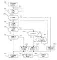
図7は、この発明の実施の形態2の車載エンジン制御装置の構成を示す回路ブロック図であり、以下、図1との相違点を中心にして説明する。なお、各図において、同一符号は、同一又は相当部分を示している。
図7において、車載エンジン制御装置(ECU)100Bの外部には、図1と同様に、車載バッテリ(以下、単にバッテリともいう。)101、電源リレー102、電源スイッチ103、運転状態検出センサ104a、104b、エンジン駆動機器105a、105b、負荷電源リレー106b、クランク角センサ107a、107bが接続されている。
車載エンジン制御装置100Bは、マイクロプロセッサ(MCPU)120Bと、監視制御回路130Bを主体として構成されている。
電源回路110は、バッテリ101から電源リレー102の出力接点102aを介して給電され、各種の安定化された制御電源電圧Vccを生成して、マイクロプロセッサ120Bと監視制御回路130B、及びその周辺回路と入出力インタフェース回路に給電する。
駆動素子111は、電源スイッチ103が閉路されたときに励磁コイル102bを付勢すると共に、ウォッチドッグタイマ134Bが正常動作しているときに発生する自己保持指令信号HLDが論理和入力されて、電源スイッチ103が一旦閉路されるとウォッチドッグ信号WD1を停止して、自己保持指令信号HLDが停止するまでは励磁コイル102bを付勢しておくことができるように構成されている。
補助電源112は、車載バッテリ101から常時給電されてRAMメモリ122の一部領域であるキープメモリに給電し、電源リレー102が消勢された状態であっても学習記憶データ、異常履歴情報データなどの重要データの記憶保持を行なうようになっている。
電源投入検出回路113は、電源スイッチ103が閉路されて電源回路110が制御出力電圧Vccを発生したことによってイニシャルパルスIPを発生して、マイクロプロセッサ120Bを初期化・始動したり、異常記憶判定回路136をリセットするようになっている。Embodiment 2. FIG.
FIG. 7 is a circuit block diagram showing the configuration of the vehicle-mounted engine control apparatus according to the second embodiment of the present invention. Hereinafter, the difference from FIG. 1 will be mainly described. In each figure, the same numerals indicate the same or corresponding parts.
In FIG. 7, similarly to FIG. 1, an in-vehicle battery (hereinafter simply referred to as a battery) 101, a
The in-vehicle
The
The driving
The
The power-on detection circuit 113 generates an initial pulse IP when the
マイクロプロセッサ120Bは、図示しない外部ツールによって制御プログラムと制御定数とが書込まれる、例えば不揮発フラッシュメモリであるプログラムメモリ121Bと、演算処理用のRAMメモリ122と、多チャンネルAD変換器123を包含している。
なお、プログラムメモリ121Bは、制御プログラムと制御定数とが書込まれるメインブロックと、第一、第二のサブブロックによって構成され、各ブロックは個別に一括消去が可能となっている。
データメモリ124Bは、プログラムメモリ121Bの一対のサブブロックを交互に使用して、前記キープメモリの中で、学習するのに時間がかかる重要な学習データや、重要センサ類
の経時変化特性、異常履歴情報等の貴重なデータが転送且つ保存されて、バッテリ101の
異常電圧低下、又はバッテリ交換時の電源断などによる貴重なデータの消失を防止するためのものとなっている。
監視制御回路130Bは、シリアルポートSR2を介してマイクロプロセッサ120Bとシリアル接続され、プログラムメモリ121Bから制御定数が転送される補助RAMメモリ132Bと、補助プログラムメモリ131と、多チャンネルAD変換器133によって構成された補助マイクロプロセッサSCPUとなっている。
ウォッチドッグタイマ134Bは、マイクロプロセッサ120Bが発生するウォッチドッグ信号WD1の周期が所定閾値を超過したときにリセット出力RSTを発生して、当該マイクロプロセッサを初期化・再起動するようになっている。The
The
The
The
The
論理和素子135aは、リセット信号RSTと、イニシャルパルスIPと、後述の親機異常検出信号ER3とを論理和して、リセット入力信号RS1をマイクロプロセッサ120Bに供給し、論理和素子135bは、リセット信号RS1と、後述の主機異常検出信号ER1と、子機異常検出信号ER2を論理和して、異常記憶判定回路136に対する異常計数信号CNTを生成するようになっている。
異常記憶判定回路136は、電源投入時にイニシャルパルスIPによってリセットされ、その後異常計数信号CNTの発生回数を計数して、当該計数値が所定値を超過すると、ゲート素子137を介して負荷電源リレー106bを消勢すると共に、退避運転指令信号EMをマイクロプロセッサ120Bに供給するようになっている。
マイクロプロセッサ120Bは、シリアルポートSR2と監視制御回路130Bを介して負荷電源投入指令信号DR2を発生し、ゲート素子137を介して負荷電源リレー106bを駆動する。
マイクロプロセッサ120Bはまた、後述する様々な自己診断機能を備えていて、マイクロ
プロセッサ120Bの制御動作に異常が発生すると自らをリセットして初期化・再起動すると共に、主機異常検出信号ER1を発生して、異常記憶判定回路136の異常計数信号CNTとなって加算計数されるようになっている。The
The abnormal
The
The
マイクロプロセッサ120Bは更に、補助マイクロプロセッサである監視制御回路130Bが発生するウォッチドッグ信号WD2を監視して、ウォッチドッグ信号WD2のパルス幅が所定値を超過すると子機異常検出信号ER2を発生して、異常記憶判定回路136が異常発生を加算計数すると共に、監視制御回路130Bは、子機異常検出信号ER2に基づいてリセット入力信号RS2が入力されて補助RAMメモリ132Bを初期化する。
監視制御回路130Bには、運転状態検出センサの一部104bと、エンジン駆動機器の一部105bが接続され、マイクロプロセッサ120Bに対して入出力信号のシリアル交信を行なうと共に、監視制御回路130Bは、マイクロプロセッサ120Bに対する質問信号を発生して、当該質問信号に対するマイクロプロセッサ120Bの回答信号が、予めプログラムメモリ121Bから補助RAMメモリ132Bへ転送されていた正解情報と不一致であることによって、親機異常検出信号ER3を発生してマイクロプロセッサ120Bをリセットして再起動するようになっている。The
The
以上のように構成された実施の形態2の車載エンジン制御装置において、まず、図7の作用動作の概要を説明する。
図7において、電源スイッチ103が閉路すると、駆動素子111を介して励磁コイル102bが付勢され、電源リレー102の出力接点102aが閉路して、バッテリ101から電源端子電圧Vinが印加される。電源回路110は、各種の安定化された制御電源電圧Vccを発生して、車載エンジン制御装置100B内の各部に給電すると共に、電源投入検出回路113がイニシャルパルスIPを発生して、異常記憶判定回路136の計数現在値をリセットし、マイクロプロセッサ120Bには、論理和素子135aを介してリセット入力信号RS1を供給する。
その結果、図8に示す初期化動作が開始され、マイクロプロセッサ120Bが正常に始動すると、図9に示す制御動作が行われ、運転状態検出センサ104a・104bの動作状態と、プログラムメモリ121Bに格納された入出力制御プログラムに応動して、エンジン駆動機器105a、105bが駆動制御される。
マイクロプロセッサ120Bは、後述の自己診断機能によって内部の異常点検を行なって、異常が発生すると自らをリセットし、図8の初期化動作が行われて再起動されると共に、主機異常検出信号ER1を発生して、異常記憶判定回路136が異常発生を計数する。In the vehicle-mounted engine control apparatus of the second embodiment configured as described above, first, an outline of the action operation of FIG. 7 will be described.
In FIG. 7, when the
As a result, the initialization operation shown in FIG. 8 is started, and when the
The
ウォッチドッグタイマ134Bは、マイクロプロセッサ120Bが発生するウォッチドッグ信号WD1のパルス幅を監視して、当該パルス幅が所定値を超過すると、リセット信号RSTを発生してマイクロプロセッサ120Bをリセットし、図8の初期化動作が行われてマイクロプロセッサ120Bが再起動されると共に、異常記憶判定回路136が異常発生を計数する。
監視制御回路130Bは、マイクロプロセッサ120Bの制御状態を監視して、マイクロプロセッサ120Bからの応答が異常であるときには、親機異常検出信号ER3を発生してマイクロプロセッサ120Bをリセットし、マイクロプロセッサ120Bは、図8の初期化動作が行われて再起動されると共に、異常記憶判定回路136が異常発生を計数する。
マイクロプロセッサ120Bは、監視制御回路130Bのウォッチドッグ信号WD2に異常があると、子機異常検出信号ER2を発生して監視制御回路130Bは補助RAMメモリ132Bの初期化を行い、異常記憶判定回路136が異常発生を計数する。
異常記憶判定回路136の計数記憶値が所定値を超過すると、ゲート素子137によって負荷電源リレー106bを消勢して、吸気弁駆動用アクチェータ106aが初期位置に復帰すると共に、マイクロプロセッサ120Bに退避運転指令信号EMが入力されて、固定のスロットル弁開度によって退避運転制御を行なう。The
The
When the watchdog signal WD2 of the
When the count storage value of the abnormal
次に、図7のマイクロプロセッサ120Bの初期化の動作説明用フローチャートである図8について説明する。
図8において、工程800から工程830に至る一連の制御フローは、図2における工程200から工程230に至る一連の制御フローと同等のものであって、工程802と、工程809のみが異なっている。
工程802は、始動点検手段826を実行するか、再起動点検手段816を実行するかを選択する初期化判定手段となるステップであり、電源投入後の初回動作ではNOの判定を行なって工程803へ移行し、工程809によって始動完了記憶が行なわれたことによって、次回からはYESの判定を行なって工程812へ移行するようになっている。
工程809では、RAMメモリ122のキープメモリ領域である第二領域の特定アドレスにある判別メモリRAMbに対して、第一の特定数値XXが書込まれている。
工程802では、判別メモリRAMbの内容が第一の特定数値XXであれば、始動点検手段826での点検が完了したものとして、YESの判定を行なうようになっている。Next, FIG. 8 which is a flowchart for explaining the initialization operation of the
In FIG. 8, a series of control flow from
Step 802 is an initialization determination unit that selects whether to execute the
In
In
次に、図7のマイクロプロセッサ120Bの運転中の動作説明用フローチャートである図9について説明する。
図9において、工程900から工程930に至る一連の制御フローは、図3における工程300から工程330に至る一連の制御フローと同等のものであって、工程903のみが異なってい
る。工程903では、工程809で第一の特定数値XXが書込まれた判別メモリRAMbに対して、第二の特定数値YYが書込まれるようになっている。
従って、改めて電源スイッチ103が閉路されて運転を再開したときには、図8の工程802
はNOの判定を行なって、始動点検手段826による点検が行なわれることになる。
なお、駐車中においてバッテリ101が異常放電したり、バッテリ端子が外されると、判別メモリRAMbの内容が不特定となり、第二の特定数値YY以外の値となっておれば、バッテリ交換等の事態を推定することができるようになっている。Next, FIG. 9 which is a flowchart for explaining operations during the operation of the
In FIG. 9, a series of control flow from
Therefore, when the
NO is determined and the inspection by the start inspection means 826 is performed.
If the
工程940は、電源スイッチ103が閉路されている状態で電源端子電圧Vinが異常低下したときに、マイクロプロセッサ120Bに対して最優先の割り込み信号が入力されることによって作動する割込み開始ステップである。
続く工程941は、判別メモリRAMbに対して、第一の特定数値XX以外の第二又は第三の特定数値YY、ZZを書込む瞬時停電処理手段となるステップである。
続く工程942は、割込み動作の終了ステップである。
瞬時停電によって電源投入検出回路113がイニシャルパルスIPを発生して、マイクロプロセッサ120Bがリセットされると、図8の初期化動作において、工程802がNOの判定を行なって、始動点検手段826による点検が行なわれることになる。
特に、工程941において、判別メモリRAMbに対して第三の特定数値ZZを書込むようにしておけば、瞬時停電が発生したことを検出して、他の制御に活用することができるものである。Step 940 is an interrupt start step that is activated when an interrupt signal having the highest priority is input to the
The
The following
When the power-on detection circuit 113 generates an initial pulse IP due to an instantaneous power failure and the
In particular, if the third specific numerical value ZZ is written in the discrimination memory RAMb in
次に、実施の形態2における非同期燃料噴射制御の動作説明用フローチャートである図10について説明する。
図10において、工程1000は、図8の工程ブロック811a、811bで示された非同期燃料噴射制御手段の動作開始ステップである。
続く工程1001は、クランク角センサ107a、107bのうち、クランク軸に設けられたクランク角センサ107aが基準点位置を通過したかどうかを判定し、基準点を通過したら工程1004aへ移行する判定ステップであり、当該基準点は、例えばクランク軸に設けられて外周に10度刻みの歯が設けられている回転円盤と対向するクランク角センサ107aが、当該回転円盤に設けられた欠歯部分を検出することによって基準点通過を検出するようになっている。
行程1004aは、応急噴射を行なう必要があるかどうかを判定して、応急噴射が必要であれば、YESの判定を行なって工程1006aへ移行し、応急噴射が不要であれば、NOの判定を行なって工程ブロック1002へ移行する応急噴射判定手段となるステップである。Next, FIG. 10 which is a flowchart for explaining the operation of the asynchronous fuel injection control in the second embodiment will be described.
In FIG. 10, a
The
In
なお、再起動点検手段816に続いて実行される、非同期燃料噴射制御手段811bにおける応急噴射判定手段1004aは、再起動点検手段816においてプログラムメモリ121Bに関するメモリ点検が行なわれたときに、応急噴射必要の判定を行ない、再起動点検手段816においてRAMメモリ122に関するメモリ点検のみが行なわれたときには、応急噴射不要の判定を行なうようになっている。
また、始動点検手段826に続いて実行される、非同期燃料噴射制御手段811aにおける応急射判定手段1004aは、環境温度と車載バッテリ電圧が所定値以下の劣悪条件にあるときに、応急噴射必要の判定を行い、環境温度と車載バッテリ電圧が劣悪とは言えない所定値以上の好条件にあるときに、応急噴射不要の判定を行なうようになっている。
行程ブロック1002は、後述の行程1003、1004b、1005を循環しながら、クランク軸の回転に応動するクランク角センサ107aと、吸気弁用カム軸の回転に応動するクランク角センサ107bの動作状態を監視して気筒群を判別し、各気筒に対する燃料噴射タイミングや点火タイミングを決定するための弁別制御を行なう気筒判別手段となっている。
なお、気筒判別手段1002は、気筒判別を開始してからエンジンが最大で2回転するまでに全気筒の判別を完了するが、気筒群の判別は、全気筒の判別よりも早いタイミングで完了するようになっている。The emergency injection determination means 1004a in the asynchronous fuel injection control means 811b, which is executed subsequent to the restart inspection means 816, is required when the memory inspection related to the
The emergency firing determination means 1004a in the asynchronous fuel injection control means 811a, which is executed following the start inspection means 826, determines whether the emergency injection is necessary when the environmental temperature and the in-vehicle battery voltage are in a bad condition below a predetermined value. When the environmental temperature and the in-vehicle battery voltage are in good conditions over a predetermined value that cannot be said to be inferior, it is determined that the emergency injection is unnecessary.
The
The cylinder discriminating means 1002 completes discrimination of all cylinders from the start of cylinder discrimination until the engine makes two revolutions at the maximum, but discrimination of cylinder groups is completed at an earlier timing than discrimination of all cylinders. It is like that.
続く工程1003は、行程ブロック1002が気筒群の判別を完了したかどうかを判定して、判定未完了であればNOの判定を行なって工程1004bへ移行し、判定完了であればYESの判定を行なって行程1007へ移行する判定ステップとなっている。
行程1004bは、応急噴射を行なう必要があるかどうかを判定して、応急噴射が必要であればYESの判定を行なって、工程1006bへ移行し、応急噴射が不要であればNOの判定を行なって、工程ブロック1005へ移行する応急噴射判定手段となるステップである。
行程1005は、クランク角センサ107a、107bのどちらかが動作したかどうかを判定し、不動作であれば、NOの判定を行なって工程1005に復帰し、動作すれば、YESの判定を行って工程1002へ循環復帰する判定ステップとなっている。
行程1006aは、図11(C)で後述する、第一の非同期燃料噴射を行なう第一の非同期燃料噴射制御手段(前期噴射)となるステップである。
行程1006bは、図11(C)で後述する、第一の非同期燃料噴射を行なう第一の非同期燃料噴射制御手段における後期噴射を停止するステップである。In
In
In
工程1007は、行程ブロック1002が全気筒の判別を完了したかどうかを判定して、判定未完了であればNOの判定を行なって、工程1008へ移行し、判定完了であればYESの判定を行なって、動作終了行程1010へ移行する判定ステップとなっている。
行程1008は、図11(B)で後述する、第二の非同期燃料噴射を行なう第二の非同期燃料噴射制御手段となるステップである。
行程1006a、1006b、又は行程1008に続いて動作終了行程1010へ移行し、図8の動作終了行程830と、図9の動作開始工程900を経て、燃料噴射制御手段906bで示した同期噴射が行なわれるようになっている。In
The
次に、図7の車載エンジン制御装置において、筒外噴射エンジンが使用された場合の動作行程図である図11について説明する。
図11(A)は、正常な同期噴射が行なわれている場合の燃料噴射タイミングIと、点火タイミングIGを示したものであって、図5(A)と全く同等である。
図11(B)は、第二の非同期燃料噴射制御手段1008によって気筒群別同時噴射が行なわれる場合であり、図5(B)と全く同等である。
図11(C)は、第一の非同期燃料噴射制御手段1006aによって全気筒の同時噴射が行なわれる場合であり、気筒3の排気行程で燃料噴射50cが行なわれると共に、気筒1の吸気行程で非同期同時噴射50aが行なわれ、気筒2の圧縮行程で燃料噴射50bが行なわれ、気筒4の燃焼行程で燃料噴射50dが行なわれている。
但し、この時点では各気筒の現在行程は全く判別されておらず、気筒3が偶然に排気行程であったことになるものである。
その結果、気筒3の燃料噴射50cに基づいて初爆53が発生し、図11(B)に比べて、更に1行程だけ早い時期に初爆が行なわれることになる。
但し、気筒1では、同時燃料噴射50aと排気行程における燃料噴射53aの2回分の燃料噴射によって燃焼行程56で燃焼が行なわれ、気筒2では、同時燃料噴射50bと排気行程における燃料噴射52bの2回分の燃料噴射によって燃焼行程55で燃焼が行なわれるので、過剰燃料となって排気ガス成分が更に悪化するのを我慢する必要がある。Next, FIG. 11, which is an operation stroke diagram when the outside-cylinder injection engine is used in the in-vehicle engine control device of FIG. 7, will be described.
FIG. 11A shows the fuel injection timing I and the ignition timing IG when normal synchronous injection is performed, and is completely equivalent to FIG. 5A.
FIG. 11 (B) shows a case where the second asynchronous fuel injection control means 1008 performs simultaneous injection by cylinder group, which is completely equivalent to FIG. 5 (B).
FIG. 11C shows a case where all the cylinders are simultaneously injected by the first asynchronous fuel injection control means 1006a. The fuel injection 50c is performed in the exhaust stroke of the cylinder 3 and the intake stroke of the
However, at this time, the current stroke of each cylinder has not been determined at all, and the cylinder 3 has been in an exhaust stroke by chance.
As a result, an
However, in the
図5(C)と図11(C)とを対比すると、図5(C)では、気筒判別の開始直後の燃料噴射タイミングにおいて、全気筒の一斉同時噴射が行なわれているのに対し、図11(C)では、気筒判別の開始直前の燃料噴射タイミングにおいて全気筒の一斉同時噴射が行なわれている。
従って、図5(C)は後期一斉噴射方式であるのに対し、図11(C)は前期一斉噴射方
式となっていて、図5(C)に比べて図11(C)の方が、初爆気筒となる気筒3の燃料噴
射タイミングが適正であり、図5(C)の場合は、初爆気筒となる気筒3の燃料噴射タイミングが1行程遅れた吸気行程となっているため、適正燃料の供給が行なえない状態となっている。
その代わりに、図11(C)の気筒4の燃料噴射50dが燃焼行程で行なわれているので、気
筒4の初回は適正燃料の供給が行なえない状態となっている。
エンジンが気筒内噴射方式である場合については、図6と全く同様である。Comparing FIG. 5C and FIG. 11C, in FIG. 5C, all the cylinders are simultaneously and simultaneously injected at the fuel injection timing immediately after the start of cylinder discrimination. In 11 (C), simultaneous injection of all cylinders is performed at the fuel injection timing immediately before the start of cylinder discrimination.
Therefore, FIG. 5 (C) shows the latter-stage simultaneous injection method, whereas FIG. 11 (C) shows the first-term simultaneous injection method, and FIG. 11 (C) is better than FIG. 5 (C). The fuel injection timing of the cylinder 3 serving as the first explosion cylinder is appropriate. In the case of FIG. 5C, the fuel injection timing of the cylinder 3 serving as the first explosion cylinder is an intake stroke delayed by one stroke. The fuel cannot be supplied.
Instead, since the fuel injection 50d of the
The case where the engine is an in-cylinder injection system is exactly the same as in FIG.
次に、図7のRAMメモリ122の初期化動作説明用フローチャートである図12につい
て説明する。
図12において、工程1200は、図8の工程ブロック808、818で示されたRAMメモリの初期設定の動作開始ステップである。
続く工程1201は、図8の行程802と同じく、判別メモリRAMbが、第一の特定数値XXであるかどうかによって、再起動であればYESの判定を行なって工程1206へ移行し、始動であればNOの判定を行なって工程1202へ移行する判定ステップである。
行程1202は、図9の行程903で判別メモリRAMbに書込まれた第二の特定数値YYが維持されているかどうかによって、バッテリ101の電源端子遮断又は異常電圧低下があった場合には、YESの判定を行なって工程1203へ移行し、第二の特定数値YYが記憶されておれば、NOの判定を行なって工程1204へ移行する判定ステップである。
行程1203は、プログラムメモリ121Bに予め格納されている制御定数のうち、RAMメモリ122の第二領域RAM2に格納される重要データのデフォルト値が、一斉にRAMメモリ122へ転送されるステップである。Next, FIG. 12 which is a flowchart for explaining the initialization operation of the
In FIG. 12,
In the
If the second specific numerical value YY written in the discrimination memory RAMb in the
続く工程1204は、図9の工程902によってデータメモリ124Bに格納保存されていた最新の学習データが、RAMメモリ122の第一領域RAM1に一斉転送されるステップである。
なお、工程902による保存が行なわれる前の段階では、製品の出荷調整時点においてプロ
グラムメモリ121Bに格納されていたデフォルト値がデータメモリ124Bに転送されてい
る。続く工程1205は、RAMメモリ122の第三領域RAM3をリセットして、例えばオールゼロを書込むステップである。
工程1206は、図9の工程ブロック920によって検出されたRAMメモリ122の異常発生アドレスが、第一領域RAM1内のものであるかどうかを判定し、第一領域RAM1内であればYESの判定を行なって工程1207へ移行し、第一領域RAM1内でなければNOの判定を行なって工程1208へ移行する判定ステップである。
It should be noted that, in the stage before the saving in
工程1207は、異常発生アドレスのメモリに対して、データメモリ124Bから保存データを転送するステップである。
工程1208は、異常発生アドレスが第二領域RAM2内のものであるかどうかを判定し、第二領域RAM2内であればYESの判定を行なって工程1209へ移行し、第二領域RAM2内でなければNOの判定を行なって動作終了工程1210へ移行する判定ステップである。
工程1209は、異常発生アドレスのメモリに対して、プログラムメモリ121Bからデフォルトデータを転送するステップである。
工程1205又は工程1209から、動作終了工程1210を経て、図8の工程809又は工程ブロック819へ復帰する。
From
以上の説明では、図8における工程ブロック808、818の詳細を述べたが、図2における工程ブロック208、218の場合もほぼ同様である。
但し、図2の場合には、図12における工程1201は、図2の工程202に相当しており、工程209でセットされた始動完了フラグが動作しているかどうかによって、再起動又は始動が判別されるようになっている。
また、図12の工程1202は、図3の工程303で書込みされたRAMaの内容を判定するものとなっている。Although the details of the process blocks 808 and 818 in FIG. 8 have been described in the above description, the process blocks 208 and 218 in FIG.
However, in the case of FIG. 2,
Further,
実施の形態2の要点と特徴
以上の説明で明らかなとおりこの発明の実施の形態2による車載エンジン制御装置は、多気筒車載エンジンの運転状態検出センサ104a、104bの動作状態に応動してエンジン駆動機器105a、105bを制御するマイクロプロセッサ120Bと、このマイクロプロセッサと協働し、クランク角センサ107a、107bの動作状態に同期して燃料噴射弁を順次開弁駆動する燃料噴射制御手段906bと、異常発生時にマイクロプロセッサ120Bを初期化・再起動する自己診断手段とを包含した不揮発性のプログラムメモリ121Bと、車載バッテリ101から常時給電されて、一部領域が電源スイッチ103の遮断状態においても記憶状態を保持するキープメモリとして使用されるRAMメモリ122と、電源スイッチ103が開路された後の遅延給電期間において、RAMメモリ122の特定領域に格納された重要データが転送保存される不揮発性のデータメモリ124Bとを備えた車載エンジン制御装置100Bであって、プログラムメモリ121Bは更に、初期化判別手段802によって選択される始動点検手段826、又は再起動点検手段816を経て、RAMメモリ122に対して所定のデフォルト値を書込み設定する初期化手段808、818となる制御プログラムを包含している。
初期化判別手段802は、エンジン始動時に実行される始動点検手段826を実行するのか、又は運転中においてマイクロプロセッサ120Bに異常が発生したことに伴う再起動点検手段816を実行するのかを判別する手段である。Key Points and Features of Embodiment 2 As is apparent from the above description, the vehicle-mounted engine control apparatus according to Embodiment 2 of the present invention is driven by the engine in response to the operating state of the operating
Initialization determination means 802 determines whether to execute start check means 826 that is executed when the engine is started, or whether to execute restart check means 816 that is associated with the occurrence of an abnormality in the
始動点検手段826は、データメモリ124Bの内容をRAMメモリ122に転送して、当該転送データのビット情報の混入・欠落の有無を検出する転送点検手段803と、プログラムメモリ121Bのビット情報の混入・欠落の有無を検出する符号点検手段806と、RAMメモリ122の読み書きが正常に行なわれるかどうかの読/書点検手段805と、吸気弁駆動用アクチェータ106aの給電回路の遮断点検手段804、とによる自己診断手段の中の複数手段によって構成されている。
再起動点検手段816は、プログラムメモリ121Bのビット情報の混入・欠落の有無を検出する符号点検手段813と、RAMメモリ122の読み書きが正常に行なわれるかどうかの読/書点検手段815との少なくとも一方の手段を含み、始動点検手段826に比べて、簡略化された自己診断項目によって構成されたメモリ点検手段である。
前記自己診断手段は更に、プログラムメモリ121BとRAMメモリ122の一部領域に関し、マイクロプロセッサ120Bの運転中において略定期的に実行されて、ビット情報の混入・欠落の発生を検出すると、マイクロプロセッサ120Bをリセットして初期化・再起動すると共に、プログラムメモリ異常又はRAMメモリ異常の異常発生フラグをセットする定期符号点検手段910、920を備えている。
再起動点検手段816において実行されるメモリ点検手段は、異常発生フラグの種別に対応したメモリの点検を行なうものである。The start check means 826 transfers the contents of the
The restart check means 816 includes at least a sign check means 813 for detecting the presence / absence of bit information in the
The self-diagnosis means is further executed on the
The memory checking means executed by the restart checking means 816 checks the memory corresponding to the type of the abnormality occurrence flag.
プログラムメモリ121Bは更に、吸気弁駆動アクチェータ106aに対する弁開度制御手段906dと、この弁開度制御手段を停止した状態でエンジンを駆動制御する退避運転手段822となる制御プログラムを包含すると共に、マイクロプロセッサ120Bには、外部診断回路130B、134Bと、異常記憶判定回路136とが付加されている。
外部診断回路130B、134Bは、マイクロプロセッサ120Bが発生するウォッチドッグ信号WD1の周期が所定閾値を超過したときに、リセット出力RSTを発生して当該マイクロプロセッサを初期化・再起動するウォッチドッグタイマ134Bであるか、または、マイクロプロセッサ120Bの制御動作を監視して、異常検出時に親機異常検出信号ER3を発生して当該マイクロプロセッサを初期化・再起動する監視制御回路130Bの少なくとも一方によって構成される。
異常記憶判定回路136は、外部診断回路130B、134Bによってマイクロプロセッサ120Bに入力されたリセット信号RS1と、自己診断手段が発生する主機異常検出信号ER1の発生回数を計数し、当該計数値が所定閾値を超過したときに吸気弁駆動アクチェータ106aの電源を遮断して、退避運転手段822を有効にするカウンタ回路であって、当該カウンタ回路の計数現在値は、電源スイッチ103の投入時に発生するイニシャルパルスIPによってリセットされると共に、マイクロプロセッサ120Bは、イニシャルパルスIPによって初期化されて始動するものである。The
When the period of the watchdog signal WD1 generated by the
The abnormal
初期化判別手段802は、判別メモリRAMbの内容によって判定され、当該判別メモリは、RAMメモリ122の中の特定アドレスが割り付けられ、始動点検手段826が実行されたことによって、判別メモリ設定手段809によって第一の特定数値XXが書込まれ、電源スイッチ103が開路された後の遅延給電期間において、判別メモリ書換手段903によって第一の特定数値以外の第二の特定数値YYが書込まれるものである。
判別メモリRAMbの内容が、第一の特定数値XX以外の値であるときには、始動点検手段826が実行され、判別メモリRAMbの内容が前記第一の特定数値XXに合致しているときには、再起動点検手段816が実行されるものである。The initialization discriminating means 802 is discriminated by the contents of the discriminating memory RAMb, and the discriminating memory is assigned by the discriminating memory setting means 809 when the specific address in the
When the content of the discrimination memory RAMb is a value other than the first specific value XX, the start check means 826 is executed, and when the content of the discrimination memory RAMb matches the first specific value XX, the restart is performed. Inspection means 816 is executed.
以上のように構成されたこの発明の実施の形態2の車載エンジン制御装置によれば、初期化判別手段802は、始動点検後と運転停止の直前にデータの書換えが行なわれる判別メモリの内容によって、始動点検と再起動点検を選択するようになっている。
従って、比較的簡易な手段によって初期化判別を行って始動点検を選択することができる
と共に、駐車中のバッテリ電圧の異常低下、又はバッテリ交換によって選択メモリの内容
が変化していることによってキープメモリの内容が信頼できないことを知ることができる
特徴がある。According to the in-vehicle engine control apparatus of the second embodiment of the present invention configured as described above, the initialization determining means 802 is based on the contents of the determination memory in which data is rewritten after the start check and immediately before the operation stop. The start inspection and the restart inspection are selected.
Accordingly, it is possible to perform initialization determination by a relatively simple means and select start-up inspection, and keep memory by changing the contents of the selected memory due to abnormal decrease in battery voltage during parking or battery replacement. There is a feature that you can know that the contents of is not reliable.
また、実施の形態2において、プログラムメモリ121Bは更に、瞬時停電処理手段941となる制御プログラムを包含し、瞬時停電処理手段941は、電源スイッチ103が閉路されている状態で電源端子電圧Vinが異常低下したときに、マイクロプロセッサ120Bに対して最優先の割り込み信号が入力されることによって作動し、判別メモリRAMbに対して、第一の特定数値XX以外の第二又は第三の特定数値YY、ZZを書込む手段である。
このように実施の形態2の車載エンジン制御装置によれば、運転中に瞬時停電が発生した場合には、瞬時停電処理手段941によって、判別メモリの内容が第二又は第三の特定数値に書き換えられるようになっている。
従って、運転中に瞬時停電が発生した場合にあっては、運転中の定期符合点検手段に依存することがない始動点検を行なうことができると共に、第三の特定数値を用いた場合には瞬時停電が発生したことを検出して、他の制御に活用することができる特徴がある。In the second embodiment, the
As described above, according to the in-vehicle engine control apparatus of the second embodiment, when an instantaneous power failure occurs during operation, the content of the discrimination memory is rewritten to the second or third specific numerical value by the instantaneous power failure processing means 941. It is supposed to be.
Therefore, if an instantaneous power failure occurs during operation, it is possible to perform a start-up inspection that does not depend on the periodic check means during operation, and when the third specific value is used, It has the feature that it can be used for other controls by detecting the occurrence of a power failure.
また、実施の形態2の車載エンジン制御装置において、監視制御回路130Bは、マイクロプロセッサ120Bとシリアル接続された補助マイクロプロセッサSCPUによって構成されている。
監視制御回路である補助マイクロプロセッサ130Bは、協働する補助プログラムメモリ131と補助RAMメモリ132Bを備え、補助RAMメモリ132Bには、プログラムメモリ121Bから制御定数が転送され、運転状態検出センサの一部104bと、エンジン駆動機器の一部105bが接続されて、マイクロプロセッサ120Bに対して入出力信号のシリアル交信を行なうと共に、マイクロプロセッサ120Bに対する質問信号を発生して、当該質問信号に対するマイクロプロセッサ120Bの回答信号が、予めプログラムメモリ121Bから補助RAMメモリ132Bに転送されていた正解情報と不一致であることによって、親機異常検出信号ER3を発生して、マイクロプロセッサ120Bをリセットして再起動するものである。
マイクロプロセッサ120Bは、監視制御回路である補助マイクロプロセッサ130Bが発生するウォッチドッグ信号WD2の周期が所定値を超過したときに、子機異常検出信号ER2を発生して、異常記憶判定回路136が異常発生を加算計数すると共に、補助マイクロプロセッサ130Bは、子機異常検出信号ER2に基づいて補助RAMメモリ132Bを初期化する。In the in-vehicle engine control apparatus according to the second embodiment, the
The
The
以上のように、実施の形態2の車載エンジン制御装置によれば、マイクロプロセッサ120Bと監視制御回路130Bは相互監視を行なっていて、監視制御回路による外部監視異常によってマイクロプロセッサはリセットされ、監視制御回路側のメモリはマイクロプロセッサからの子機異常検出信号によって、監視制御回路側で初期化されるようになっている。
従って、マイクロプロセッサは、運転中に定期符号点検を行なうと共に、監視制御回路によって常時外部監視されていて、安全性が向上すると共に、メモリの初期化が分担されて、再起動初期化時間が短縮される特徴がある。
また、監視制御回路による外部監視異常によってマイクロプロセッサがリセットされた時の再起動点検では、メモリ点検が行なわれないので、再起動初期化時間が短縮される特徴
がある。As described above, according to the in-vehicle engine control apparatus of the second embodiment, the
Therefore, the microprocessor performs periodic code check during operation and is constantly monitored externally by the supervisory control circuit, improving safety, sharing memory initialization, and shortening restart initialization time. There are features to be done.
Further, in the restart check when the microprocessor is reset due to an external monitoring abnormality by the monitor control circuit, the memory check is not performed, so that the restart initialization time is shortened.
100A、100B 車載エンジン制御装置
101 車載バッテリ
102 電源リレー
103 電源スイッチ
104a、104b 運転状態検出センサ
105a、105b エンジン駆動機器
106a 吸気弁駆動アクチェータ
107a、107b クランク角センサ
120A、120B マイクロプロセッサ
121A、121B プログラムメモリ
122 RAMメモリ
124A、124B データメモリ
130A 監視制御回路(集積回路素子)
130B 監視制御回路(補助マイクロプロセッサ)
131 補助プログラムメモリ
132A バッファメモリ
132B 補助RAMメモリ
134A、134B ウォッチドッグタイマ
136 異常記憶判定回路
202、802 初期化判別手段
203、803 転送点検手段
204、804 遮断点検手段
205、805 読/書点検手段
206、806 符号点検手段
208、218 初期化手段
210、810 要否判定手段
211a、211b 非同期燃料噴射制御手段
811a、811b 非同期燃料噴射制御手段
213、813 符号点検手段
215、815 読/書点検手段
216、816 再起動点検手段
221、821 始動点検手段
306、906 入出力制御手段
306a、906a 気筒判別手段
306b、906b 燃料噴射制御手段(同期噴射)
306d、906d 吸気弁開度制御手段
310、320 定期符号点検手段
910、920 定期符号点検手段
941 瞬時停電処理手段
404、1004a 応急噴射判定手段
406 第一の非同期燃料噴射制御手段(後期噴射)
1006a 第一の非同期燃料噴射制御手段(前期噴射)
408、1008 第二の非同期燃料噴射制御手段
ER1 主機異常検出信号
ER2 子機異常検出信号
ER3 親機常検出信号
WD1 ウォッチドッグ信号
WD2 ウォッチドッグ信号
RST リセット信号
CNT 異常計数信号
IP イニシャルパルス
EM 退避運転指令信号
Vcc 制御電源電圧
Vin 電源端子電圧100A, 100B In-vehicle engine controller
101 Car battery
102 Power relay
103 Power switch
104a, 104b Operating state detection sensor
105a, 105b Engine drive equipment
106a Intake valve drive actuator
107a, 107b Crank angle sensor
120A, 120B microprocessor
121A, 121B Program memory
122 RAM memory
124A, 124B data memory
130A supervisory control circuit (integrated circuit element)
130B Supervisory control circuit (auxiliary microprocessor)
131 Auxiliary program memory
132A buffer memory
132B Auxiliary RAM memory
134A, 134B Watchdog timer
136 Abnormal memory judgment circuit
202, 802 Initialization discrimination means
203, 803 Transfer inspection means
204, 804 Blocking inspection means
205, 805 Reading / writing inspection means
206,806 Sign check means
208, 218 Initialization means
210, 810 Necessity judgment means
211a, 211b Asynchronous fuel injection control means
811a, 811b Asynchronous fuel injection control means
213, 813 Code check means
215, 815 Reading / writing inspection means
216, 816 Reboot inspection means
221, 821 Start-up inspection means
306, 906 I / O control means
306a, 906a Cylinder discrimination means
306b, 906b Fuel injection control means (synchronous injection)
306d, 906d Intake valve opening control means
310, 320 Periodic code check means
910, 920 Periodic code check means
941 Instantaneous power failure processing method
404, 1004a Emergency injection judgment means
406 First asynchronous fuel injection control means (late injection)
1006a First asynchronous fuel injection control means (early injection)
408, 1008 Second asynchronous fuel injection control means
ER1 Main engine abnormality detection signal
ER2 Slave unit error detection signal
ER3 Master unit detection signal
WD1 Watchdog signal
WD2 Watchdog signal
RST reset signal
CNT abnormal count signal
IP initial pulse
EM Evacuation operation command signal
Vcc control power supply voltage
Vin Power supply terminal voltage
Claims (14)
Translated fromJapanese前記マイクロプロセッサと協働し、クランク角センサの動作状態に同期して燃料噴射弁を順次開弁駆動する燃料噴射制御手段と、異常発生時に前記マイクロプロセッサを初期化再起動する自己診断手段とを包含したプログラムメモリと、
車載バッテリから給電されて、一部領域が電源スイッチの遮断状態においても記憶状態を保持するキープメモリとして使用されるRAMメモリと、
前記電源スイッチが開路された後の遅延給電期間において前記RAMメモリの特定領域に格納された重要データが転送保存されるデータメモリとを備えた車載エンジン制御装置であって、
前記プログラムメモリは更に、初期化判別手段によって選択される始動点検手段又は再起動点検手段を経て、前記RAMメモリに対して所定のデフォルト値を書込み設定する初期化手段となる制御プログラムと、非同期燃料噴射制御手段となる制御プログラムを包含し、
前記初期化判別手段は、エンジン始動時に実行される前記始動点検手段を実行するのか
、又は運転中において前記マイクロプロセッサに異常が発生したことに伴う再起動点検手段を実行するのかを判別する手段であり、
前記始動点検手段は、前記データメモリの内容を前記RAMメモリに転送して当該転送データのビット情報の混入・欠落の有無を検出する転送点検手段と、前記プログラムメモリのビット情報の混入・欠落の有無を検出する符号点検手段と、前記RAMメモリの読み書きが正常に行なわれるかどうかの読/書点検手段と、吸気弁駆動用アクチェータの給電回路の遮断点検手段とによる自己診断手段の中の複数手段によって構成され、
前記再起動点検手段は、前記プログラムメモリのビット情報の混入・欠落の有無を検出する符号点検手段と、前記RAMメモリの読み書きが正常に行なわれるかどうかの読/書点検手段との少なくとも一方の手段を含み、前記始動点検手段に比べて簡略化された自己診断項目によって構成されたメモリ点検手段であり、
前記自己診断手段は更に、前記プログラムメモリと前記RAMメモリの一部領域に関し
、前記マイクロプロセッサの運転中において略定期的に実行されてビット情報の混入・欠落の発生を検出すると、前記マイクロプロセッサをリセットして初期化・再起動すると共に、プログラムメモリ異常又はRAMメモリ異常の異常発生フラグをセットする定期符号点検手段を備え、前記再起動点検手段において実行されるメモリ点検手段は、前記異常発生フラグの種別に対応したメモリの点検を行なうものであり、
前記非同期燃料噴射制御手段は、少なくとも前記再起動点検手段による初期化が完了し
、前記クランク角センサに基づく気筒判別が完了して各気筒に対して順次クランク角センサの動作と連動同期した燃料噴射制御が行われる前段階において、エンジンの始動用電動機が駆動されていないにも関わらず、複数気筒に対して先行同時噴射を行なって前記マイクロプロセッサがリセットされて惰性回転中のエンジンが再駆動されるまでの時間を短縮する手段であることを特徴とする車載エンジン制御装置。A microprocessor that controls the engine driving device in response to the operating state of the operating state detection sensor of the multi-cylinder on-vehicle engine;
In cooperation with the microprocessor, fuel injection control means for sequentially driving the fuel injection valves to open in synchronization with the operating state of the crank angle sensor; and self-diagnosis means for initializing and restarting the microprocessor when an abnormality occurs Included program memory, and
A RAM memory that is powered as an in-vehicle battery and is used as a keep memory that retains the memory state even when a partial area is in a power-off state,
An in-vehicle engine control device including a data memory in which important data stored in a specific area of the RAM memory is transferred and stored in a delay power feeding period after the power switch is opened;
The program memory further includes a control program serving as an initialization means for writing and setting a predetermined default value in the RAM memory via a start check means or a restart check means selected by the initialization determination means,and an asynchronous fuel. Includes a control program thatis an injection control means ,
The initialization determining means is a means for determining whether to execute the start check means that is executed when the engine is started, or whether to execute a restart check means that accompanies an abnormality in the microprocessor during operation. Yes,
The start checking means transfers the contents of the data memory to the RAM memory and detects the presence / absence of mixing / missing bit information of the transfer data, and the mixing / missing of bit information of the program memory. A plurality of self-diagnostic means including a sign checking means for detecting presence / absence, a reading / writing check means for whether or not the RAM memory is normally read and written, and a shut-off checking means for the feeding circuit of the intake valve driving actuator Constituted by means,
The restart check means includes at least one of a code check means for detecting the presence or absence of mixing / missing bit information in the program memory and a read / write check means for determining whether the RAM memory is normally read or written. A memory checking means including self-diagnostic items that are simplified compared to the start-up checking means.
The self-diagnosis means further executes the microprocessor about a part of the program memory and the RAM memory when the occurrence of bit information mixing / missing is detected substantially periodically during the operation of the microprocessor. Initializing / restarting by resetting, and having periodic code checking means for setting an abnormality occurrence flag of program memory abnormality or RAM memory abnormality, the memory inspection means executed in the restarting inspection means includes the abnormality occurrence flagis intended to carry out the inspection of memory corresponding to thetype,
The asynchronous fuel injection control means has been initialized at least by the restart check means.
The engine starting motor is not driven at the stage before the cylinder discrimination based on the crank angle sensor is completed and the fuel injection control synchronized with the operation of the crank angle sensor is sequentially performed for each cylinder. Regardless of this, the vehicle-mounted engine control device isa means for shortening the time required for the simultaneous simultaneous injection to a plurality of cylinders to reset the microprocessor and restart the engine during inertial rotation .
前記外部診断回路は、前記マイクロプロセッサが発生するウォッチドッグ信号の周期が所定閾値を超過したときにリセット出力を発生して、当該マイクロプロセッサを初期化・再起動するウォッチドッグタイマであるか、または前記マイクロプロセッサの制御動作を監視して、異常検出時に親機異常検出信号を発生して当該マイクロプロセッサを初期化・再起動する監視制御回路の少なくとも一方によって構成され、
前記異常記憶判定回路は、前記外部診断回路によって前記マイクロプロセッサに入力されたリセット信号と、前記自己診断手段が発生する主機異常検出信号の発生回数を計数し、当該計数値が所定閾値を超過したときに、前記吸気弁駆動アクチェータの電源を遮断して前記退避運転手段を有効にするカウンタ回路であって、当該カウンタ回路の計数現在値は前記電源スイッチの投入時に発生するイニシャルパルスによってリセットされると共に、前記マイクロプロセッサは、前記イニシャルパルスによって初期化されて始動するものであることを特徴とする請求項1に記載の車載エンジン制御装置。The program memory further includes a valve opening control means for the intake valve drive actuator, and a control program serving as a evacuation operation means for driving and controlling the engine with the valve opening control means stopped. Has an external diagnostic circuit and an abnormal memory determination circuit,
The external diagnostic circuit is a watchdog timer that generates a reset output when a period of a watchdog signal generated by the microprocessor exceeds a predetermined threshold, and initializes and restarts the microprocessor; or It is constituted by at least one of a monitoring control circuit that monitors the control operation of the microprocessor, generates a master unit abnormality detection signal when abnormality is detected, and initializes and restarts the microprocessor,
The abnormal memory determination circuit counts the number of occurrences of a reset signal input to the microprocessor by the external diagnostic circuit and a main engine abnormality detection signal generated by the self-diagnosis means, and the count value exceeds a predetermined threshold value. A counter circuit that shuts off the power supply of the intake valve drive actuator to enable the retreat operation means, and the current count value of the counter circuit is reset by an initial pulse generated when the power switch is turned on The on-board engine control apparatus according to claim 1, wherein the microprocessor is initialized and started by the initial pulse.
前記判別メモリの内容が、前記第一の特定数値以外の値であるときには始動点検手段が実行され、前記判別メモリの内容が、前記第一の特定数値に合致しているときには再起動点検手段が実行されるものであることを特徴とする請求項1〜請求項3のいずれか1項に記載の車載エンジン制御装置。The initialization determining means is determined according to the contents of the determination memory. The determination memory is assigned a specific address in the RAM memory, and the start inspection means is executed. In the delayed power supply period after the specific numerical value is written and the power switch is opened, the second specific numerical value other than the first specific numerical value is written by the discrimination memory rewriting means,
When the content of the determination memory is a value other than the first specific numerical value, a start check means is executed, and when the content of the determination memory matches the first specific numerical value, a restart check means is The in-vehicle engine control device according to any one of claims 1 to 3, wherein the on-vehicle engine control device is executed.
前記瞬時停電処理手段は、前記電源スイッチが閉路されている状態で電源端子電圧が異常低下したときに、前記マイクロプロセッサに対して最優先の割り込み信号が入力されることによって作動し、前記判別メモリに対して前記第一の特定数値以外の第二又は第三の特定数値を書込む手段であることを特徴とする請求項5に記載の車載エンジン制御装置。The program memory further includes a control program serving as an instantaneous power failure processing means,
The instantaneous power failure processing means operates when an interrupt signal having the highest priority is input to the microprocessor when the power supply terminal voltage is abnormally lowered in a state where the power switch is closed. 6. The on-vehicle engine control device according to claim 5, wherein said on-vehicle engine control device is means for writing a second or third specific numerical value other than said first specific numerical value.
ロックに分割されて実施され、前記プログラムメモリ異常に関する異常発生フラグは、各点検ブロックに対応した複数のフラグを備えており、前記再起動点検手段においては、発生した異常フラグに対応したブロックのプログラムメモリの符号点検が実行されることを特徴とする請求項1〜請求項3のいずれか1項に記載の車載エンジン制御装置。In the periodic code checking means, the code checking means for the program memory is divided into a plurality of blocks, and the abnormality occurrence flag relating to the program memory abnormality includes a plurality of flags corresponding to each check block, The in-vehicle engine control device according to any one of claims 1 to 3, wherein the start check means performs a code check of a program memory of a block corresponding to the generated abnormality flag.
前記マイクロプロセッサは、前記監視制御回路との間のシリアル交信に異常が発生したときに子機異常検出信号を発生して、前記異常記憶判定回路が異常発生を加算計数すると共
に、前記監視制御回路は更に、前記子機異常検出信号に基づいて、前記バッファメモリを初期化することを特徴とする請求項2に記載の車載エンジン制御装置。The supervisory control circuit is configured by an integrated circuit element that is serially connected to the microprocessor and includes a buffer memory to which a control constant is transferred from the program memory and an arithmetic circuit unit, and the integrated circuit element includes the operation state. A part of the detection sensor and a part of the engine driving device are connected, and the supervisory control circuit performs serial communication of input / output signals to the microprocessor and generates an interrogation signal for the microprocessor, When the response signal of the microprocessor in response to the question signal does not match the correct answer information previously transferred from the program memory to the buffer memory, a master unit abnormality detection signal is generated, and the microprocessor is reset and restarted. Is,
The microprocessor generates a slave unit abnormality detection signal when an abnormality occurs in serial communication with the monitoring control circuit, and the abnormal memory determination circuit adds and counts the occurrence of abnormality, and the monitoring control circuit The vehicle-mounted engine control apparatus according to claim 2, further comprising: initializing the buffer memory based on the slave unit abnormality detection signal.
前記マイクロプロセッサは、前記補助マイクロプロセッサが発生するウォッチドッグ信号の周期が所定値を超過したときに子機異常検出信号を発生して、前記異常記憶判定回路が異常発生を加算計数すると共に、前記補助マイクロプロセッサは前記子機異常検出信号に基づいて前記補助RAMメモリを初期化することを特徴とする請求項2に記載の車載エンジン制御装置。The supervisory control circuit is constituted by an auxiliary microprocessor serially connected to the microprocessor, and the auxiliary microprocessor includes a cooperating auxiliary program memory and an auxiliary RAM memory, and the auxiliary RAM memory includes the program memory. A control constant is transferred from the control unit, a part of the operation state detection sensor and a part of the engine drive device are connected, and serial communication of input / output signals to the microprocessor is performed, and a question signal to the microprocessor is transmitted. And the microprocessor answer signal corresponding to the question signal does not match the correct answer information previously transferred from the program memory to the auxiliary RAM memory. To reset,
The microprocessor generates a slave unit abnormality detection signal when a period of a watchdog signal generated by the auxiliary microprocessor exceeds a predetermined value, and the abnormal memory determination circuit adds and counts the occurrence of abnormality, The in-vehicle engine control apparatus according to claim 2, wherein the auxiliary microprocessor initializes the auxiliary RAM memory based on the slave unit abnormality detection signal.
Priority Applications (3)
| Application Number | Priority Date | Filing Date | Title |
|---|---|---|---|
| JP2007196060AJP4420944B2 (en) | 2007-07-27 | 2007-07-27 | In-vehicle engine controller |
| US12/059,829US7962274B2 (en) | 2007-07-27 | 2008-03-31 | Vehicle-mounted engine control apparatus |
| DE102008017060ADE102008017060B4 (en) | 2007-07-27 | 2008-04-03 | On-vehicle engine control device |
Applications Claiming Priority (1)
| Application Number | Priority Date | Filing Date | Title |
|---|---|---|---|
| JP2007196060AJP4420944B2 (en) | 2007-07-27 | 2007-07-27 | In-vehicle engine controller |
Publications (2)
| Publication Number | Publication Date |
|---|---|
| JP2009030543A JP2009030543A (en) | 2009-02-12 |
| JP4420944B2true JP4420944B2 (en) | 2010-02-24 |
Family
ID=40176061
Family Applications (1)
| Application Number | Title | Priority Date | Filing Date |
|---|---|---|---|
| JP2007196060AExpired - Fee RelatedJP4420944B2 (en) | 2007-07-27 | 2007-07-27 | In-vehicle engine controller |
Country Status (3)
| Country | Link |
|---|---|
| US (1) | US7962274B2 (en) |
| JP (1) | JP4420944B2 (en) |
| DE (1) | DE102008017060B4 (en) |
Families Citing this family (29)
| Publication number | Priority date | Publication date | Assignee | Title |
|---|---|---|---|---|
| JP5272507B2 (en)* | 2008-05-12 | 2013-08-28 | 株式会社デンソー | Electronic control unit |
| JP4820428B2 (en)* | 2009-03-26 | 2011-11-24 | 三菱電機株式会社 | Engine control device |
| JP5199991B2 (en)* | 2009-12-24 | 2013-05-15 | 本田技研工業株式会社 | Seat belt device |
| JP5299525B2 (en)* | 2010-01-27 | 2013-09-25 | トヨタ自動車株式会社 | Control system abnormality determination device and abnormality determination method |
| JP5276697B2 (en) | 2011-06-15 | 2013-08-28 | 三菱電機株式会社 | On-board engine start control device |
| JP5778536B2 (en)* | 2011-09-14 | 2015-09-16 | 株式会社ケーヒン | Electronic control device and vehicle control system |
| JP5406951B2 (en)* | 2012-01-30 | 2014-02-05 | 京セラドキュメントソリューションズ株式会社 | Power supply control apparatus, electronic device, and image forming apparatus |
| JP5997008B2 (en)* | 2012-02-08 | 2016-09-21 | ルネサスエレクトロニクス株式会社 | Semiconductor integrated circuit device and data processing system |
| JP2013213445A (en)* | 2012-04-02 | 2013-10-17 | Suzuki Motor Corp | Engine fuel injection device |
| JP2014019416A (en)* | 2012-07-24 | 2014-02-03 | Hitachi Automotive Systems Ltd | Vehicle control device |
| US20140075094A1 (en)* | 2012-09-12 | 2014-03-13 | GM Global Technology Operations LLC | Method to implement a binary flag in flash memory |
| CN103347033B (en)* | 2012-12-11 | 2016-12-07 | 深圳市合正汽车电子有限公司 | Vehicle-mounted communication method and system |
| JP5583244B1 (en)* | 2013-06-10 | 2014-09-03 | 三菱電機株式会社 | Electronic control apparatus having integrated circuit element and single-unit inspection apparatus for the integrated circuit element |
| ITTO20130646A1 (en)* | 2013-07-30 | 2015-01-31 | Magneti Marelli Spa | IMPLEMENTATION IN COMPLIANCE WITH ASIL B OF SAFETY-BASED AUTOLYTIC FUNCTIONS THROUGH AN INTEGRATED CIRCUIT WITH HIGH DIAGNOSTICABILITY DESIGNED ACCORDING TO QUALITY STANDARDS |
| JP6299564B2 (en)* | 2014-11-12 | 2018-03-28 | 株式会社デンソー | Electronic control unit |
| US10054062B1 (en)* | 2014-12-15 | 2018-08-21 | Brunswick Corporation | Systems and methods for controlling an electronic throttle valve |
| DE102015226818B4 (en) | 2015-01-08 | 2019-12-05 | Denso Corporation | Electronic control device |
| JP6816345B2 (en)* | 2015-04-24 | 2021-01-20 | 富士電機株式会社 | Drive control device |
| WO2017017829A1 (en) | 2015-07-30 | 2017-02-02 | 三菱電機株式会社 | Program execution device, program execution system, and program execution method |
| CN107015915B (en)* | 2015-10-28 | 2019-07-26 | 威盛电子股份有限公司 | Nonvolatile memory device and control method thereof |
| JP6642073B2 (en)* | 2016-02-10 | 2020-02-05 | 三菱自動車工業株式会社 | Failure diagnosis method for electric power supply system of electric vehicle |
| JP6887277B2 (en)* | 2017-03-24 | 2021-06-16 | 日立Astemo株式会社 | Electronic control device for automobiles |
| US11002202B2 (en)* | 2018-08-21 | 2021-05-11 | Cummins Inc. | Deep reinforcement learning for air handling control |
| FR3086695B1 (en)* | 2018-09-27 | 2021-04-16 | Continental Automotive France | RUGGED SYNCHRONIZATION PROCESS WITH REVERSE ROTATION |
| US11002238B2 (en)* | 2019-02-13 | 2021-05-11 | Pratt & Whitney Canada Corp. | Method and system for starting an engine |
| WO2020255997A1 (en)* | 2019-06-21 | 2020-12-24 | 京セラ株式会社 | Electronic apparatus, vehicle, and control method |
| JP7600921B2 (en)* | 2021-07-30 | 2024-12-17 | 株式会社デンソー | Motor Control Device |
| CN117055533A (en)* | 2023-09-18 | 2023-11-14 | 一汽解放汽车有限公司 | Vehicle-mounted system fault processing method, device, equipment and medium |
| CN119705311A (en)* | 2023-09-28 | 2025-03-28 | 法雷奥汽车内部控制(深圳)有限公司 | Control circuit, control system and control method for limp-home function of vehicle |
Family Cites Families (21)
| Publication number | Priority date | Publication date | Assignee | Title |
|---|---|---|---|---|
| JPS58197556A (en) | 1982-05-12 | 1983-11-17 | Mitsubishi Electric Corp | Computer device |
| JPS59549A (en)* | 1982-06-24 | 1984-01-05 | Toyota Motor Corp | Digital control method for internal combustion engine |
| JPS62237536A (en) | 1986-04-08 | 1987-10-17 | Mitsubishi Electric Corp | Electronic computer |
| JPS63109545A (en) | 1986-10-28 | 1988-05-14 | Mitsubishi Electric Corp | Hardware self-diagnosis method |
| US4768013A (en)* | 1987-07-01 | 1988-08-30 | Nissan Motor Company, Limited | Method and apparatus for diagnosing failure in idle switch for internal combustion engines |
| JPH03141836A (en) | 1989-10-26 | 1991-06-17 | Aisan Ind Co Ltd | Electronic control type fuel injection device |
| JPH0579373A (en) | 1991-09-14 | 1993-03-30 | Mazda Motor Corp | Control system for engine |
| JPH06214831A (en) | 1993-01-18 | 1994-08-05 | Mitsubishi Electric Corp | Abnormality detector for central processing unit |
| DE19780310T1 (en) | 1996-03-01 | 1998-04-23 | Mitsubishi Motors Corp | Cylinder discriminator for an internal combustion engine |
| US6285931B1 (en)* | 1998-02-05 | 2001-09-04 | Denso Corporation | Vehicle information communication system and method capable of communicating with external management station |
| JP3881177B2 (en) | 2001-02-06 | 2007-02-14 | 三菱電機株式会社 | Vehicle control device |
| US6775609B2 (en)* | 2001-09-27 | 2004-08-10 | Denso Corporation | Electronic control unit for vehicle having operation monitoring function and fail-safe function |
| JP2003097345A (en) | 2001-09-27 | 2003-04-03 | Denso Corp | Electronic control device for vehicle |
| JP3778349B2 (en) | 2001-11-20 | 2006-05-24 | 三菱電機株式会社 | Fuel injection control device for start-up of internal combustion engine |
| JP3847664B2 (en)* | 2002-05-30 | 2006-11-22 | 三菱電機株式会社 | In-vehicle engine controller |
| JP3794485B2 (en) | 2002-06-26 | 2006-07-05 | 三菱電機株式会社 | Cylinder discrimination device for internal combustion engine |
| JP4296050B2 (en) | 2003-07-14 | 2009-07-15 | 三菱電機株式会社 | Electronic control unit |
| JP4627150B2 (en)* | 2004-05-24 | 2011-02-09 | 三菱電機株式会社 | Signal processing device |
| JP3969494B2 (en)* | 2004-08-31 | 2007-09-05 | 三菱電機株式会社 | In-vehicle electronic control unit |
| JP4446168B2 (en) | 2004-11-25 | 2010-04-07 | 株式会社デンソー | Automotive control device |
| JP4354939B2 (en)* | 2005-09-20 | 2009-10-28 | 三菱電機株式会社 | Analog input signal processing circuit |
- 2007
- 2007-07-27JPJP2007196060Apatent/JP4420944B2/ennot_activeExpired - Fee Related
- 2008
- 2008-03-31USUS12/059,829patent/US7962274B2/ennot_activeExpired - Fee Related
- 2008-04-03DEDE102008017060Apatent/DE102008017060B4/ennot_activeExpired - Fee Related
Also Published As
| Publication number | Publication date |
|---|---|
| DE102008017060B4 (en) | 2013-10-17 |
| US20090030587A1 (en) | 2009-01-29 |
| DE102008017060A1 (en) | 2009-02-05 |
| US7962274B2 (en) | 2011-06-14 |
| JP2009030543A (en) | 2009-02-12 |
Similar Documents
| Publication | Publication Date | Title |
|---|---|---|
| JP4420944B2 (en) | In-vehicle engine controller | |
| US7912600B2 (en) | In-vehicle electronic control apparatus having monitoring control circuit | |
| JP4343945B2 (en) | Electronic control unit | |
| JP4636118B2 (en) | Electronic device and program | |
| US20060287805A1 (en) | Electronic control apparatus which responds to shut-down command by executing specific processing prior to ceasing operation | |
| JP2003214233A (en) | Electronic control device for vehicle | |
| JP6145345B2 (en) | Electronic control unit for automobile | |
| JP5967059B2 (en) | Electronic control device for vehicle | |
| JP4042466B2 (en) | Memory diagnostic device and control device | |
| JP2006322332A (en) | Failure detection method for starter drive circuit and economical running control device | |
| JP4501838B2 (en) | Vehicle abnormality diagnosis device | |
| JP5664454B2 (en) | Electronic control device for vehicle | |
| JP3883842B2 (en) | Electronic control device for vehicle | |
| CN110872998B (en) | Method for verifying CVVD position learning result and CVVD system for verifying CVVD position learning result | |
| JP6444847B2 (en) | Electronic control device for vehicle | |
| JP4457969B2 (en) | VEHICLE CONTROL METHOD AND ELECTRONIC CONTROL DEVICE | |
| US20110145529A1 (en) | Controller | |
| JP3804454B2 (en) | Electronic control device | |
| JP2006327217A (en) | Program for vehicle control and electronic control device for vehicle | |
| JP2007198290A (en) | Vehicle abnormality diagnosis device | |
| JP5874694B2 (en) | Diagnostic device for internal combustion engine | |
| JPH116461A (en) | Engine control device and recording medium thereof | |
| US7853768B2 (en) | Electronic control apparatus and method for writing backup data in electronic control apparatus | |
| JP4412222B2 (en) | VEHICLE CONTROL METHOD AND ELECTRONIC CONTROL DEVICE | |
| JP2001182607A (en) | Vehicle controlling device |
Legal Events
| Date | Code | Title | Description |
|---|---|---|---|
| A977 | Report on retrieval | Free format text:JAPANESE INTERMEDIATE CODE: A971007 Effective date:20090625 | |
| A131 | Notification of reasons for refusal | Free format text:JAPANESE INTERMEDIATE CODE: A131 Effective date:20090630 | |
| A521 | Written amendment | Free format text:JAPANESE INTERMEDIATE CODE: A523 Effective date:20090827 | |
| TRDD | Decision of grant or rejection written | ||
| A01 | Written decision to grant a patent or to grant a registration (utility model) | Free format text:JAPANESE INTERMEDIATE CODE: A01 Effective date:20091110 | |
| A01 | Written decision to grant a patent or to grant a registration (utility model) | Free format text:JAPANESE INTERMEDIATE CODE: A01 | |
| A61 | First payment of annual fees (during grant procedure) | Free format text:JAPANESE INTERMEDIATE CODE: A61 Effective date:20091201 | |
| FPAY | Renewal fee payment (event date is renewal date of database) | Free format text:PAYMENT UNTIL: 20121211 Year of fee payment:3 | |
| R151 | Written notification of patent or utility model registration | Ref document number:4420944 Country of ref document:JP Free format text:JAPANESE INTERMEDIATE CODE: R151 | |
| FPAY | Renewal fee payment (event date is renewal date of database) | Free format text:PAYMENT UNTIL: 20121211 Year of fee payment:3 | |
| FPAY | Renewal fee payment (event date is renewal date of database) | Free format text:PAYMENT UNTIL: 20121211 Year of fee payment:3 | |
| FPAY | Renewal fee payment (event date is renewal date of database) | Free format text:PAYMENT UNTIL: 20131211 Year of fee payment:4 | |
| R250 | Receipt of annual fees | Free format text:JAPANESE INTERMEDIATE CODE: R250 | |
| R250 | Receipt of annual fees | Free format text:JAPANESE INTERMEDIATE CODE: R250 | |
| R250 | Receipt of annual fees | Free format text:JAPANESE INTERMEDIATE CODE: R250 | |
| LAPS | Cancellation because of no payment of annual fees |