JP4420605B2 - Humidifier having a structure that prevents back flow of liquid through the humidifier inlet - Google Patents
Humidifier having a structure that prevents back flow of liquid through the humidifier inletDownload PDFInfo
- Publication number
- JP4420605B2 JP4420605B2JP2002565664AJP2002565664AJP4420605B2JP 4420605 B2JP4420605 B2JP 4420605B2JP 2002565664 AJP2002565664 AJP 2002565664AJP 2002565664 AJP2002565664 AJP 2002565664AJP 4420605 B2JP4420605 B2JP 4420605B2
- Authority
- JP
- Japan
- Prior art keywords
- chamber
- inlet
- humidifier
- liquid
- outlet
- Prior art date
- Legal status (The legal status is an assumption and is not a legal conclusion. Google has not performed a legal analysis and makes no representation as to the accuracy of the status listed.)
- Expired - Fee Related
Links
Images


Classifications
- A—HUMAN NECESSITIES
- A61—MEDICAL OR VETERINARY SCIENCE; HYGIENE
- A61M—DEVICES FOR INTRODUCING MEDIA INTO, OR ONTO, THE BODY; DEVICES FOR TRANSDUCING BODY MEDIA OR FOR TAKING MEDIA FROM THE BODY; DEVICES FOR PRODUCING OR ENDING SLEEP OR STUPOR
- A61M16/00—Devices for influencing the respiratory system of patients by gas treatment, e.g. ventilators; Tracheal tubes
- A61M16/10—Preparation of respiratory gases or vapours
- A61M16/14—Preparation of respiratory gases or vapours by mixing different fluids, one of them being in a liquid phase
- A61M16/16—Devices to humidify the respiration air
- A—HUMAN NECESSITIES
- A61—MEDICAL OR VETERINARY SCIENCE; HYGIENE
- A61M—DEVICES FOR INTRODUCING MEDIA INTO, OR ONTO, THE BODY; DEVICES FOR TRANSDUCING BODY MEDIA OR FOR TAKING MEDIA FROM THE BODY; DEVICES FOR PRODUCING OR ENDING SLEEP OR STUPOR
- A61M16/00—Devices for influencing the respiratory system of patients by gas treatment, e.g. ventilators; Tracheal tubes
- A61M16/10—Preparation of respiratory gases or vapours
- A61M16/1075—Preparation of respiratory gases or vapours by influencing the temperature
- A61M16/109—Preparation of respiratory gases or vapours by influencing the temperature the humidifying liquid or the beneficial agent
- A—HUMAN NECESSITIES
- A61—MEDICAL OR VETERINARY SCIENCE; HYGIENE
- A61M—DEVICES FOR INTRODUCING MEDIA INTO, OR ONTO, THE BODY; DEVICES FOR TRANSDUCING BODY MEDIA OR FOR TAKING MEDIA FROM THE BODY; DEVICES FOR PRODUCING OR ENDING SLEEP OR STUPOR
- A61M16/00—Devices for influencing the respiratory system of patients by gas treatment, e.g. ventilators; Tracheal tubes
- A61M16/0057—Pumps therefor
- A61M16/0066—Blowers or centrifugal pumps
- A—HUMAN NECESSITIES
- A61—MEDICAL OR VETERINARY SCIENCE; HYGIENE
- A61M—DEVICES FOR INTRODUCING MEDIA INTO, OR ONTO, THE BODY; DEVICES FOR TRANSDUCING BODY MEDIA OR FOR TAKING MEDIA FROM THE BODY; DEVICES FOR PRODUCING OR ENDING SLEEP OR STUPOR
- A61M2205/00—General characteristics of the apparatus
- A61M2205/21—General characteristics of the apparatus insensitive to tilting or inclination, e.g. spill-over prevention
- Y—GENERAL TAGGING OF NEW TECHNOLOGICAL DEVELOPMENTS; GENERAL TAGGING OF CROSS-SECTIONAL TECHNOLOGIES SPANNING OVER SEVERAL SECTIONS OF THE IPC; TECHNICAL SUBJECTS COVERED BY FORMER USPC CROSS-REFERENCE ART COLLECTIONS [XRACs] AND DIGESTS
- Y10—TECHNICAL SUBJECTS COVERED BY FORMER USPC
- Y10S—TECHNICAL SUBJECTS COVERED BY FORMER USPC CROSS-REFERENCE ART COLLECTIONS [XRACs] AND DIGESTS
- Y10S261/00—Gas and liquid contact apparatus
- Y10S261/65—Vaporizers
Landscapes
- Health & Medical Sciences (AREA)
- Emergency Medicine (AREA)
- Pulmonology (AREA)
- Engineering & Computer Science (AREA)
- Anesthesiology (AREA)
- Biomedical Technology (AREA)
- Heart & Thoracic Surgery (AREA)
- Hematology (AREA)
- Life Sciences & Earth Sciences (AREA)
- Animal Behavior & Ethology (AREA)
- General Health & Medical Sciences (AREA)
- Public Health (AREA)
- Veterinary Medicine (AREA)
- Air Humidification (AREA)
- Structures Of Non-Positive Displacement Pumps (AREA)
Description
Translated fromJapanese本願は、2001年2月16日に出願されたオーストラリア仮出願PR3117および2001年8月27日に出願されたオーストラリア仮出願PR7288に基づく優先権を主張しており、これらの出願の明細書および図面を完全に援用する。 This application claims priority based on Australian provisional application PR3117 filed on February 16, 2001 and Australian provisional application PR7288 filed on August 27, 2001, and the specification and drawings of these applications. Is fully incorporated.
本発明は、非侵襲型圧力換気(NIPPV)または持続的気道陽圧(CPAP)のために用いられる装置のような呼吸可能なガスを供給する装置とともに使用されるための加湿器に関する。 The present invention relates to a humidifier for use with a device that supplies a breathable gas, such as a device used for non-invasive pressure ventilation (NIPPV) or continuous positive airway pressure (CPAP).
NIPPVまたはCPAP用の装置は典型的には送風機を備えており、送風機の出力は、空気配送管を介して、マスクのような患者用インタフェースに接続されている。患者の中には、加湿された空気が与えられたらNIPPVまたはCPAPがもっと快適であろうと考える患者もいる。この目的のために、製造者はよく、送風機の出口と患者用インタフェースとの間の空気回路に取り付けられ得る加湿器を供給している。加湿器は、典型的には、水の容器を有しており、送風機から加湿器に入ってくる周囲の空気が、患者用インタフェースへと続く前に水との接触を通じて水分を集めるように構成されている。 Devices for NIPPV or CPAP typically include a blower, and the output of the blower is connected to a patient interface such as a mask via an air delivery tube. Some patients think that NIPPV or CPAP would be more comfortable when given humid air. For this purpose, manufacturers often supply humidifiers that can be attached to the air circuit between the outlet of the blower and the patient interface. A humidifier typically has a container of water and is configured so that ambient air entering the humidifier from the blower collects moisture through contact with the water before continuing to the patient interface. Has been.
典型的には、送風機と加湿器とは、柔軟性のある導管を介して接続された別個の構成要素である。空気配送管は加湿器の出口を患者用インタフェースマスクに接続する。あるいは、送風機と加湿器とは、一緒に固定して接続されていてもよい。送風機の出口からの空気は加湿器の入口へと進み、そこで加湿されてから、空気配送管へと進む。いずれか構成でも起こり得る問題点は、もし加湿器が正常な向きに対して傾いていると、水が加湿器から送風機の出口にこぼれて、送風機の電気回路に損害を与えるかもしれず、また感染管理の問題を引き起こす可能性があるということである。
なお、本出願に対応する外国の特許出願においては下記の文献が発見または提出されている。
The following documents have been found or submitted in foreign patent applications corresponding to this application.
本発明の一局面は、先行技術の不具合を実質的に解消する、または少なくとも改善することである。 One aspect of the present invention is to substantially eliminate or at least improve the deficiencies of the prior art.
他の局面は、加湿器に含まれている液が加湿器の入口から望ましくないのに出てしまうことを実質的に防ぐように適応されているCPAP装置用の加湿器を提供することである。 Another aspect is to provide a humidifier for a CPAP device that is adapted to substantially prevent the liquid contained in the humidifier from undesirably exiting from the inlet of the humidifier. .
他の局面は、CPAP装置に直接接続可能である加湿器を提供することである。 Another aspect is to provide a humidifier that can be directly connected to a CPAP device.
他の局面は、供給チューブを実質的になくすように、CPAP装置に直接接続することができる入口を有する加湿器を提供することである。 Another aspect is to provide a humidifier having an inlet that can be directly connected to the CPAP device so as to substantially eliminate the supply tube.
他の局面は、中に含まれている液を加熱することが出来る加湿器を提供することである。 Another aspect is to provide a humidifier capable of heating the liquid contained therein.
本発明の一実施形態は、呼吸可能なガスを加湿する装置を有している。この装置は、中に液体を保持するように構成された加湿器本体と、加湿器本体の内部に通じており、送風機の出口に接続可能である入口と、加湿器本体の内部に通じており、患者用供給管に接続可能である出口とを備えている。加湿器の内部は、加湿器本体が動作時の直立している向きから回転されるときに、液体からの液がその入口から加湿器本体を出て行くことを防ぐように構成されている。 One embodiment of the present invention includes a device for humidifying breathable gas. This device leads to a humidifier body configured to hold liquid therein, an interior of the humidifier body, an inlet connectable to the outlet of the blower, and an interior of the humidifier body And an outlet that is connectable to the patient supply tube. The interior of the humidifier is configured to prevent liquid from the liquid from exiting the humidifier body from its inlet when the humidifier body is rotated from an upright orientation during operation.
このようにして、液が送風機の出口へ入り、送風機に損害を与える可能性を実質的に防ぐことができる。 In this way, the possibility of liquid entering the outlet of the blower and damaging the blower can be substantially prevented.
また装置は、入口および出口を有する第一のチャンバであって、好ましくは第一のチャンバ入口が送風機の出口に接続可能である第一のチャンバと、好ましくは第一のチャンバ出口に接続された入口ならびに好ましくは患者用供給管に接続可能である出口を有する第二のチャンバとを有しており、第二のチャンバは好ましくは、液体のための収容容量を有している。第一のチャンバの入口および出口、ならびに第一および第二のチャンバの体積は、加湿器が動作時の直立している向きにあるときには液体が第二のチャンバに含まれ、加湿器の他の相対位置では、液体は、少なくとも第二のチャンバか、第一および第二のチャンバ内の第一のチャンバ入口のレベルよりも低いレベルに保持されるように適応されていてもよい。 The apparatus is also a first chamber having an inlet and an outlet, preferably connected to the first chamber, wherein the first chamber inlet is connectable to the blower outlet, and preferably to the first chamber outlet. A second chamber having an inlet and preferably an outlet connectable to the patient supply tube, the second chamber preferably having a capacity for liquid. The inlet and outlet of the first chamber, and the volume of the first and second chambers are such that liquid is contained in the second chamber when the humidifier is in the upright orientation during operation, and the other of the humidifier In the relative position, the liquid may be adapted to be held at a level that is lower than at least the second chamber or the first chamber inlet in the first and second chambers.
第二のチャンバの体積は、第一のチャンバの体積よりも大きくてもよい。 The volume of the second chamber may be larger than the volume of the first chamber.
第一のチャンバは、装置の動作時の直立している向きにおいて、第二のチャンバよりも実質的に上に位置してもよい。
第一のチャンバの入口および出口は、第一のチャンバの隣接する対向している区画に位置していてもよい。The first chamber may be located substantially above the second chamber in an upright orientation during operation of the device.
The inlet and outlet of the first chamber may be located in adjacent opposing compartments of the first chamber.
第二のチャンバの出口は、第一のチャンバの入口よりも、第一のチャンバ出口近くにあってもよい。
第二のチャンバのベースの少なくとも一部は、熱伝導材料から形成されていてもよい。The outlet of the second chamber may be closer to the first chamber outlet than the inlet of the first chamber.
At least a portion of the base of the second chamber may be formed from a thermally conductive material.
熱伝導部分は、ベースの開口部を覆う金属製のキャップの形態であってもよい。 The heat conducting portion may be in the form of a metal cap that covers the opening in the base.
装置は、上面カバーと、ベースと、上面カバーおよびベースの間に配置された分割部とを有していてもよく、ベースはその中に形成される容器を規定し、容器は、好ましくは、装置の動作時の向きにおいて液体を保持する。 The apparatus may have a top cover, a base, and a split disposed between the top cover and the base, the base defining a container formed therein, the container preferably Holds liquid in the operating orientation of the device.
上面カバーと分割部とは一緒に第一のチャンバを規定し、容器と分割部とは一緒に第二のチャンバを規定してもよい。 The top cover and the divider may define the first chamber together, and the container and the divider may define the second chamber together.
第一のチャンバの入口と第二のチャンバの出口とは上面カバーに形成され、第一のチャンバの出口と第二のチャンバの入口とは分割部に形成されてもよく、第一のチャンバの出口および第二のチャンバの入口は、第一および第二のチャンバを通じさせている分割部内の一つの開口によって規定されてもよい。 The inlet of the first chamber and the outlet of the second chamber may be formed in the top cover, and the outlet of the first chamber and the inlet of the second chamber may be formed in a divided portion. The outlet and the inlet of the second chamber may be defined by a single opening in the split through the first and second chambers.
分割部は第一および第二の区画を規定してもよく、好ましくは第一の区画は上面カバーと一緒に第一のチャンバを規定する。 The divider may define first and second compartments, preferably the first compartment defines a first chamber with the top cover.
分割部はリブで隔てられている複数の開口を有していてもよく、これらは、第二のチャンバから上面カバーに形成された第二のチャンバ出口への流体の行き来を提供し得る。 The divider may have a plurality of openings separated by ribs, which may provide fluid flow from the second chamber to the second chamber outlet formed in the top cover.
上面カバーおよびベースは比較的剛性の高いポリマー材料から形成され、分割部は比較的弾力性のある材料から形成されていてもよい。 The top cover and the base may be formed from a relatively rigid polymer material, and the dividing portion may be formed from a relatively elastic material.
第一のチャンバ入口は送風機の出口に接続されていてもよく、第一のチャンバ出口は第二のチャンバ入口に接続されていてもよく、第二のチャンバ出口は患者用供給管に接続されていてもよく、第二のチャンバの第二のチャンバ入口よりも下かつ後ろの部分は、液体の体積よりも大きい体積を規定してもよい。 The first chamber inlet may be connected to the blower outlet, the first chamber outlet may be connected to the second chamber inlet, and the second chamber outlet is connected to the patient supply tube The portion below and behind the second chamber inlet of the second chamber may define a volume that is greater than the volume of the liquid.
第一のチャンバ入口と第二のチャンバ入口との間かつ第二のチャンバ入口よりも下の第二のチャンバの部分は、液体の体積よりも大きい体積を規定してもよい。 The portion of the second chamber between the first chamber inlet and the second chamber inlet and below the second chamber inlet may define a volume that is greater than the volume of the liquid.
第一のチャンバ入口と第二のチャンバ出口との間の第一のチャンバの部分および第二のチャンバの部分は、液体の体積よりも大きい体積を規定してもよい。 The portion of the first chamber and the portion of the second chamber between the first chamber inlet and the second chamber outlet may define a volume that is greater than the volume of the liquid.
本発明の他の実施形態は、上述した呼吸可能なガスを加湿する装置を備えているCPAP装置を有している。 Another embodiment of the invention includes a CPAP device that includes a device for humidifying the breathable gas described above.
本発明の他の実施形態は、流体の容器と流体の通路とを中に規定する加湿器本体を備えるCPAP装置用の加湿器を有している。加湿器本体は、分割部材を間に有する第一および第二のチャンバを有している。分割部材は、第一のチャンバと第二のチャンバとを通じさせる開口部を有している。送風機(図示せず)からの空気は、第一のチャンバ入口を介して第一のチャンバに入り、第二のチャンバ出口を通って第二のチャンバから出て行く。流体通路は、入口、出口、開口部および少なくとも第一のチャンバおよび第二のチャンバの部分を有している。加湿器は、最大体積Vmaxの液体を収容するように設計されている。加湿器の動作時の向きにおいては、液体は第二のチャンバの底部にある。加湿器の動作時の位置に関しては、開口部は入口の前方横にある。第一および第二のチャンバは、第一のチャンバの真下にある第二のチャンバの第一の部分の体積がVmaxよりも大きいように構成される。あるいは、第一のチャンバの横に配置されている第二のチャンバの第二の部分の体積はVmaxよりも大きい。さらに、入口前方の第二のチャンバの部分プラス入口前方の第一のチャンバの部分の体積がVmaxよりも大きい。加えて、入口の横の第二のチャンバの部分プラス入口の横の第一のチャンバの部分の体積はVmaxよりも大きい。Another embodiment of the invention includes a humidifier for a CPAP device that includes a humidifier body defining a fluid container and a fluid passageway therein. The humidifier body has first and second chambers with a split member in between. The dividing member has an opening that allows the first chamber and the second chamber to pass through. Air from a blower (not shown) enters the first chamber through the first chamber inlet and exits the second chamber through the second chamber outlet. The fluid passage has an inlet, an outlet, an opening and at least a portion of the first chamber and the second chamber. Humidifier is designed to accommodate the liquid up to the volume Vmax. In the operational orientation of the humidifier, the liquid is at the bottom of the second chamber. With respect to the operating position of the humidifier, the opening is next to the front of the inlet. The first and second chamber is configured such that the volume of the first portion of the second chamber just below the first chamber is greater than Vmax. Alternatively, the volume of the second portion of the second chamber is arranged beside the first chamber is greater than Vmax. Furthermore, the volume of a portion plus the inlet first chamber portion of the front of the inlet in front of the second chamber is greater than Vmax. In addition, the volume of a portion plus the inlet of the first chamber portion of the lateral inlet side of the second chamber is greater than Vmax.
本発明のさらに他の実施形態は、第一および第二のチャンバを有するCPAP装置用の加湿器を有しており、加湿器への入口は第一のチャンバに通じており、加湿器からの出口は第二のチャンバに通じており、第一および第二のチャンバはそれらの間を伸びている開口部を介して相互に通じている。入口と開口部とは互いに対して、加湿器のいかなる向きについても、加湿器内に存在する液のレベルが入口および開口部の少なくとも一つよりも下であるように配置されている。 Yet another embodiment of the present invention has a humidifier for a CPAP device having first and second chambers, the inlet to the humidifier leading to the first chamber, from the humidifier. The outlet communicates with the second chamber, and the first and second chambers communicate with each other through an opening extending therebetween. The inlet and the opening are arranged with respect to each other such that for any orientation of the humidifier, the level of liquid present in the humidifier is below at least one of the inlet and the opening.
発明のある実施形態がある特徴を有するものとして、ここで示して説明しているが、示され、説明された実施形態の少なくとも一つ以上の特徴のそれぞれまたは組み合わせに基づいて、発明の代替的な実施形態が提供され得ることを当業者は認識するであろう。 Although certain embodiments of the invention have been shown and described herein as having certain features, alternatives to the invention may be based on each or combination of at least one or more features of the shown and described embodiments. Those skilled in the art will recognize that various embodiments may be provided.
なお、上記の発明の概要は、本発明の必要な特徴の全てを列挙したものではなく、これらの特徴群のサブコンビネーションもまた、発明となりうる。 The above summary of the invention does not enumerate all the necessary features of the present invention, and sub-combinations of these feature groups can also be the invention.
以下、発明の実施の形態を通じて本発明を説明するが、以下の実施形態は特許請求の範囲にかかる発明を限定するものではなく、また実施形態の中で説明されている特徴の組み合わせの全てが発明の解決手段に必須であるとは限らない。 Hereinafter, the present invention will be described through embodiments of the invention. However, the following embodiments do not limit the invention according to the scope of claims, and all combinations of features described in the embodiments are included. It is not necessarily essential for the solution of the invention.
本発明の利点は、以下の本発明の詳細な説明を添付の図面とともに考慮すると容易に理解されるであろう。 The advantages of the present invention will be readily understood by considering the following detailed description of the invention in conjunction with the accompanying drawings.
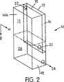
図1は、10で示される本発明の加湿器の一実施形態を概略的に示している。加湿器10は流体の容器と流体の通路とをその中に規定する加湿器本体12を有している。また、加湿器本体12と分割部材18とによって2つのチャンバ14、16が規定される。分割部材18は、それを貫いてチャンバ14、16を互いに通じさせている開口部20を有している。送風機(図示せず)からの空気は、第一のチャンバ入口22を介して第一のチャンバ16内に到達する。空気は第二のチャンバ出口24を介して第二のチャンバ14から出て行く。流体通路は、入口22と、出口24と、開口部20と、少なくとも、チャンバ14の一部とチャンバ16の一部とを含んでいる。加湿器10は、最大体積Vmaxの液体26を収容するように設計されている。FIG. 1 schematically illustrates one embodiment of the humidifier of the present invention, indicated at 10. The
図1に表されている動作時の向きにおいては、液体26は第二のチャンバ14の底の部分にある。図1に図示されている加湿器10の向きに関して、例えば、開口部20は第一のチャンバ入口22の前の横に(例えば、チャンバ16の対角線上で入口22に対向する端に)ある。図示されているように、第一のチャンバ16の真下にきている第二のチャンバ14の第一の部分14Aの体積は、その高さが相対的に高くなっているためにVmaxよりも大きい。加えて、第一のチャンバ16の横に配置されている第二のチャンバ14の第二の部分14Bの体積は、Vmaxよりも大きい。さらに、第二のチャンバ14の入口22の前にある部分プラス第一のチャンバ16の入口22の前にある部分の体積は、Vmaxよりも大きい。加えて、入口22の横にある第二のチャンバ14の部分プラス入口22の横の第一のチャンバ16の部分の体積はVmaxよりも大きい。したがって、加湿器10の体積を最小にするために、第一のチャンバの入口22は、できるだけ加湿器本体12の一側面に、できるだけ加湿器本体12の後ろ側に配置される。In the operational orientation depicted in FIG. 1, the liquid 26 is in the bottom portion of the
図1〜5に示す加湿器10の実施形態は、例えば、直立している正常動作位置(図1に大まかに示されている)から不注意に回転されたときに、液体26からの液が加湿器の入口22から出てしまうことを防ぐように構成されている。この理由から、加湿器10は、入口22から液が出て行くことを許すことなく、直立している動作位置から約120°回転されることが可能であることが好ましい。加湿器10は、入口22から液が出るのを許すことなく、約80°〜110°、直立している動作位置から回転されることが可能であることがさらに好ましい。図1に示す加湿器10の実施形態に関しては、加湿器10は、入口22から液が出るのを許すことなく直立している動作位置から約90°回転されることが可能であることが特に好ましいと考えられる。なぜなら、加湿器10の側面は実質的に平坦で垂直であるために、加湿器10を一つの側面を下にして置くことが容易にできるからである。しかし、当然のことながら、加湿器10は、加湿器10の特定の構成に応じて、90°より多く、あるいは少なく回転されることが可能であることが望ましいかもしれない。加湿器10は、直立している動作位置以外の向きに不注意で向けられたときに、加湿器10の入口から液が出て行くことを防ぐように設計されているが、例えば、加湿器10を乱暴に突いたり、急に、かつ/または繰り返し回転したりすることによって、液が入口から出ることを意図的に可能にすることも可能であってもよい。加湿器の入口から液が出ることが極めて望ましくないような状況においては、チャンバの構成(例えば体積)、入口および出口のサイズおよび配置、ならびにチャンバ間を相互に通じさせる開口のサイズおよび配置は、加湿器の入口を液が出る可能性を減らすために、図示されている実施形態から変更されてもよい。 The embodiment of the
図2に示すように、チャンバ14、16、入口22および出口24の構成は、加湿器10が軸αの回りを90°まで時計回りに回転された場合に、液体26は、出口に隣接している第二のチャンバ14の第二の部分14Bと第一のチャンバ16の一部にとどまることを意味する。この状況において、液体26の液は出口24からは出るかもしれないが、入口22から出て送風機に戻ることはない。 As shown in FIG. 2, the configuration of
同様に、図3に示すように、加湿器10を軸αの回りを90°まで(図1に示す位置に対して)反時計回りに回転した場合には、液体26は第二のチャンバ14の第一の部分14Aにとどまるが、開口部20から第一のチャンバ16へこぼれ出ることはない。 Similarly, as shown in FIG. 3, when the
図4に示すように、加湿器10を軸βの回りを90°まで(図1に示す位置に対して)時計回りに回転した場合には、液体26は第二のチャンバ14の後方部分に溜まり、開口部20から第一のチャンバ16にこぼれ出ることはない。 As shown in FIG. 4, when the
図5に示すように、加湿器10を軸βの回りを90°まで(図1に示す位置に対して)半時計回りに回転した場合には、液体26は、第一および第二のチャンバ14、16の前方部分にとどまり、第一のチャンバ入口22を通ってこぼれて戻ることはない。さらに、液体26の液は、第二のチャンバ出口24を通じて加湿器10から排出される。 As shown in FIG. 5, when the
図1〜5に示す実施形態では、加湿器10は、略矩形である外部形状を有している。図示されているように、入口22は、直立している位置において正面から見たときに、左上側にある送風機出口に対応するように配置される。したがって、加湿器入口22は、直立している位置において正面から見たときに、左上側の加湿器10の背面に位置する。加湿器出口24は、直立している位置において正面から見たときに、正面右上側にある。しかし当然のことながら、入口および出口は、送風機出口の位置に対応するように再配置されることが可能である。 In the embodiment shown in FIGS. 1 to 5, the
図1〜5に示す加湿器10の向きのそれぞれについて、液体26のレベルは常に、入口22、ならびに第一および第二のチャンバ16、14を相互に通じさせている開口部20の少なくとも一方のレベルよりも下である。このようにして、入口22が液体26のレベルよりも下にあるような場合(例えば、図3および4に示す向きにおける場合)に、開口部20は液体26のレベルよりも上に配置され、液がそれを通って流れて入口22を出ることを防ぐ。逆に、開口部20が液体26のレベルよりも下に配置されている場合(例えば図2および5に示される向きにおける場合)には、入口22は液体26のレベルよりも上に配置される。したがって、液は開口部20を通って流るが、入口22から出ることは防がれる。 For each of the
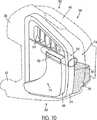
図6は、本発明による加湿器30の他の実施形態を示している。加湿器30は、入口32と出口34とを有しており、これらは両方とも加湿器30の内部と通じている。加湿器30の内部は、液体のための容器および流体通路を規定する。流体通路は、入口32および出口34のそれぞれと通じており、流体通路を通って流れる流体(例えば高い圧力での呼吸可能なガス)が液体にさらされるように構成されている。また、加湿器30は、送風機を有するNIPPVまたはCPAP装置(図示せず)への取り外し可能な接続に適応されている。接続されると、送風機の出力が入口32に取り付けられる。送風機からの空気が入口32に入り、流体通路を通って流れ、出口34へ、そして患者へと続く前に、液体との接触を通じて水分を集める。 FIG. 6 shows another embodiment of a
加湿器30は、例えば上で援用された同時係属出願ならびに、本願と同日に出願され、ここで完全に援用される「睡眠時呼吸障害を治療する装置における空気圧信号の監視」と題する同時係属出願第WO02/066107号で述べられているように、信号強度を落とすことなく、あるいは加湿器内の信号減衰にのために比較的大きな補正係数を必要とすることなくCPAP圧の監視を可能にするために付加的な内部通路を有してもよいと考えられる。 The
図7に示すように、加湿器30は、上面カバー36と、ガスケット38と、ベース40とを有している。ガスケット38は上面カバー36とベース40との間に配置されており、上面カバー36とベース40とはスライドクリップ72によって一つに固定される(図6を参照せよ。)。当然のことながら、他の適切な締め具配置および構成も可能である。例えば、上面カバー36とベース40とは、スナップどめまたは他の協働構成を有して形成されてもよい。あるいは、他のタイプの機械的な締め具を用いてもよい。上面カバー36は、ポリスルホン(例えば、ビーピー アモコ ポリマース社 (BP Amoco Polymers)によって製造されるグレードUDEL P1700)のような比較的剛性のある材料から形成されてもよく、入口32と出口34とを有する。ガスケット38は、シリコーンゴム(例えば、ダウコーニングによって製造されるSILASTIC 94-595-IIC)のような比較的弾力性のある材料から形成されてもよく、チャネル構造46によって第一および第二の区画42および44に分割される。第一の区画42は、盛り上がった部分48を有しており、部分48はそれを貫いて垂直に伸びている第一の開口50を有している。第二の部分44は、それを貫いて垂直に伸びている複数の第二の開口52を有している。第二の開口52は、リブ54によって互いに隔てられている。また上面カバー36は、ガスケット38のチャネル構造46に対応し、それを中に受ける分割壁構造56(図8)を有していてもよい。ガスケット38は、その周縁部回りに形成された密閉フランジ58を有している。ベース40は、上面カバー36と同じまたは類似した剛性のあるポリマー材料から形成されてもよく、その中に形成された容器60と、底部62と、底部62から上方に伸びている側壁64とを有していてもよい。またベース40は、除去可能なブリッジ構造66を有していてもよく、これは容器60を、ガスケット38の区画42および44に対応する2つの区画68および70に分割する。 As shown in FIG. 7, the
図8に示すように、加湿器30を組み立てるためには、ガスケット38をベース40に取り付ける。ガスケット38のフランジ58は、ベース40の側壁64の上側の縁部と密閉係合を形成する。そして上面カバー36がガスケット38を覆い、ガスケット38を密閉するように、加湿器30の対向する側部上のスライドクリップ72(図6)を介して、上面カバー36をベース40に取り付ける。除去可能なブリッジ構造66はガスケット38の中間部を垂直に支持する。図示するように、ガスケット38のチャネル構造46の下に面している面がブリッジ構造66の上に面している面と係合する。組み立てられると、ガスケットの第一の区画42と、上面カバー36と、上面カバーの分割壁構造とが一緒に第一のチャンバ74を形成する。ベース40の容器60はガスケット38とともに第二のチャンバ76を形成する。したがって第一のチャンバ74は第二のチャンバ76の上方に位置し、第二のチャンバ76の体積は第一のチャンバ74の体積よりも大きい。第一および第二のチャンバ74、76は、ガスケット38内の第一の開口50を介して互いに通じている。第二のチャンバ76は、ガスケット38内の第二の開口52を介して出口34と通じている。 As shown in FIG. 8, in order to assemble the
使用時には、ベース40から上面カバー36および密閉ガスケット38を取り除いた後に、所定の最大体積の液がベース40の容器60に注入される。そして上面カバー36および密閉ガスケット38がベース40に再び取り付けられる。図9に示すように、液体78は、加湿器10が加湿器30の直立している動作時の向きにあるときに第二のチャンバ76に保持される。送風機からの呼吸可能なガスは入口32に入り、第一のチャンバ74を通って第一の開口50に入って行く。ガスは、開口50を通り抜けて、第二のチャンバ76に入り、そこでガスケット38内の開口52から出て出口34(図6)から出て行く前に、液体78との接触によって加湿される。 In use, after removing the
加湿器30の動作時の直立している向きにおいては、図9に示すように、液体78の81で示される液のレベルは開口50よりも下である。したがって、液体78からの液は入口32を通って出ることができず、NIPPVまたはCPAP装置の電子的な要素に損害を与える危険はない。しかしながら、液体78は、加湿器30の向きに応じて加湿器30内を移動する。したがって、加湿器30は、非直立の向きにおいて液体78の液が入口32を通って出ることを実質的に防いで、加湿器30に接続されているNIPPVまたはCPAP装置に損害を与えることを避けるように構成されている。 In the upright orientation during operation of the
図1〜5に示されている実施形態と同様に、図6〜13に示されている加湿器30の実施形態は、例えば直立している正常な動作位置(図6に大まかに示されている)から不注意に回転されたときに、液体78からの液が入口32を通って出ることを防ぐように構成されている。この理由から加湿器30は、好ましくは、液が入口32から出ることを許すことなく、直立している動作位置から約120°回転されることが可能である。より好ましくは、加湿器30は、液が入口32から出ることを許すことなく、直立している動作位置から約80°〜110°回転されることが可能である。特に好ましくは、加湿器30は、液が入口32から出ることを許すことなく、直立している動作位置から約90°回転されることが可能である。しかし、当然のことではあるが、加湿器30が90°より大きく、あるいは小さく回転されることが可能であることが望ましいこともある。加湿器30は、直立している動作位置以外の他の位置に不注意で向けられたときに、加湿器30の入口から液が出ることを防ぐように構成されているが、例えば加湿器30を乱暴に突く、あるいは急におよび/または繰り返し回転させることによって、液が入口から出ることができるように意図的に構成することも可能であることに留意されたい。加湿器の入口から液が出ることが極めて望ましくないような状況下では、チャンバの構成(例えば体積)、入口および出口のサイズおよび配置、ならびにチャンバを相互に通じさせている開口のサイズおよび配置は、加湿器の入口を液が出る可能性を減らすように、図示されている実施形態から変更されてもよい。 Similar to the embodiment shown in FIGS. 1-5, the embodiment of the
図10〜13に示されている加湿器30の向きのそれぞれに関して、液体78のレベルは常に、入口32、ならびに第一および第二のチャンバ74、76を相互に通じさせている開口50の少なくとも一方のレベルよりも下である。このようにして、入口32が液体78のレベルよりも下に配置されている場合(例えば図10および12に示されている向きにおける場合)には、開口50は液体78のレベルよりも上方に配置され、液がそれを通って流れて入口32を出ることを防止する。逆に、開口50が液体78のレベルよりも下に配置されている場合(図11および13に示されている向きにおける場合)には、入口32は液体78のレベルよりも上方に配置される。したがって、液は開口50を通って流れるが、入口32から出ることは防止される。 For each of the
図10において、加湿器30は、入口32に隣接する加湿器30の側面に相当する側面80が出口34に隣接する加湿器30の側面に相当する側面82の下に向けられるように動作時の直立している向きから約90°の角度に回転されている。ガスケット38の盛り上がった部分48は第二のチャンバ76の体積を増やしているので、液体78は第二のチャンバ76内のみにとどまり、液体78のレベル81は第一の開口50よりも下のままである。したがって、液は入口32から出ない。 In FIG. 10, the
図11において、加湿器30は、側面82が側面80の下にあるように(すなわち、図11に示されている向きから180°ひっくり返されたように)、動作時の直立している向きから約90°の角度まで回転されている。液体78のレベル81は開口52の(少なくとも初期には)上にあり、液は開口52を通って出口34を出る。しかし、液体78のレベル81が入口32よりも下にあるので、液は入口32を通って出ない。出口34を通って出る液は、一般的には許容することができる。なぜならNIPPVまたはCPAP装置に損害を与える危険は一般的にはないからである。 In FIG. 11, the
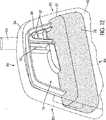
図12において、加湿器30は、入口32が位置している側面に相当する84で示される後側の側面が、出口34が位置している側面に相当する86で示される前側の側面よりも下にあるように、動作時の直立している向きから約90°の角度まで回転されている。図示されているように、液体78は実質的に第二のチャンバ76内にとどまり、液体78のレベル81は第一の開口50よりも下のままである。したがって、水は入口32を通って出ることはない。 In FIG. 12, the
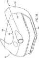
図13は、加湿器30が、前側の側面86が後側の側面84の下にあるように動作時の直立している向きから約90°の角度まで傾いているときを示している。図示されているように、液体78は第一および第二のチャンバ74、76の前方の部分内にある。液体78のレベル81は開口50のレベルよりも少なくとも初期には上にあるので、液は開口50を通って第一のチャンバ74に流れる。しかし、入口32はこの向きにおいては液体78のレベルよりも上に配置されているので、液は入口32を通って出ない。 FIG. 13 shows when the
したがって加湿器30は、液体78が(a)第二のチャンバ76のみの中、あるいは(b)入口32よりも下のレベルの第一のチャンバ74の部分および第二のチャンバ76の部分の中に確実に配置されるようにして、動作時の直立している向きから約90°の角度までの加湿器30の向きで、液が入口32を通って出ることを防ぐ。示された実施形態では、加湿器30の数多くの特徴がこの機能を確実にすることに寄与している。これらには、入口32および第一の開口50の相対位置が含まれる。特に、入口32および第一の開口50は、第一のチャンバ74の対向する端に配置される。また、第二のチャンバ76の体積は第一のチャンバ74の体積よりも大きい。これは、第一のチャンバ74から移動した液が開口50を通ってオーバーフローすることなく、第二のチャンバ76内に収容されるようにガスケット38の盛り上がった部分48によって補助される。さらに、出口34は、入口32よりも第一の開口50近くに位置しており、これは液が入口32を通ってではなく、出口34を通って出ることを確実にする一助となる。 Accordingly, the
それゆえに、加湿器30は、動作時の直立している向きから約90°の角度までの他の向きに加湿器30があるときに、NIPPVまたはCPAP装置に損害を与えるかもしれない、水が入口32から出る危険性を実質的に防ぐ、あるいは減少させる。 Therefore, the
加湿器30は、CPAP装置のための後付けあるいは追加の構成要素として用いられ得る。この使用法を容易にするために、CPAP装置と加湿器30との間を接続するように構成された接続構造100を提供することが好ましい。図14および15に示すように、接続構造100は、ハウジング102を備えており、これは、その中に加湿器30が配置され得る略水平に伸びている容器104を提供する。ハウジング102は、その上に加湿器30を支持するように構成されたベース部106と、加湿器30を定位置に固定するように構成された保持部108とを提供する。図16に示すように、保持部108は、ベース部106に略平行に伸びており、ベース部106の上方に離して配置されている。図14に戻ると、加湿器30は凹部110を有して形成されている。凹部110は開いており、かつその中に保持部108を受けるように相補的な形状を有している。 The
加湿器30の接続構造100への接続を容易にするために、図16において120で示される加湿器の他の実施形態は、固定機構122を備えていることが考えられる。図示されているように、固定機構122は、弾力的に付勢された引き手部材124を有しており、引き手部材124はそれから略下方に伸びている1つ以上のロックつまみ(locking lug)126を有している。引き手部材124は、加湿器120の前方の端(加湿器120の後方の端が接続構造100に隣接していると仮定している)に配置されており、一対の弾力性のある脚部128によって弾力的に付勢されている。脚部128の後方部分は、加湿器120の底部側面上に設けられている対応するポケット構造130内に比較的しっかりと保持されている。リブ132は加湿器120の底部側面から下方に伸びており、弾性脚部128と加湿器120の底部側面との間に空間を規定するように脚部128の中間部に係合する。このようにして、引き手部材124は弾性脚部128によって略下方に付勢されるが、脚部128の弾力的な付勢に対抗して手動で上方に動かされ(例えば、引っ張られ)得る。 In order to facilitate connection of the
図15に示すように、ベース部106の前方部分は、略上方に開いているつまみ受け凹部134を有しており、加湿器120が容器104内に配置されたときに凹部134内につまみ126が配置される。加湿器120が容器104内に挿入されると、脚部128がつまみ126を凹部134の方へと弾力的に付勢する。それによって、つまみ126と凹部134とは加湿器120を容器104内に固定する。加湿器120を容器104から取り除くためには、凹部134からつまみ126を引き出すように引き手部材124を上方に引っ張る。そして加湿器120が容器104から略水平に引っ張られる。 As shown in FIG. 15, the front portion of the
図17は接続構造100の後方側を示している。接続構造100の後方側は、接続構造100をCPAP装置に固定するための保持機構140を提供する。保持機構140は、ハウジング102の後方部分内に一連の開口142を有していてもよい。開口142は、その中で、例えば、CPAP装置によって提供される留め金(prong)あるいはタブを受ける。図18に示すように、各開口142内にロック部材144が設けられてもよい。ロック部材144は、それぞれの開口142を部分的に囲む位置へと弾力的に付勢されている。同様に図18に示すように、ボタン構造146の手動による動きがロック部材144をそれらの付勢された位置から動かして、開口142を実質的に完全に開放するように、ボタン構造146をロック部材144に連結してもよい。CPAP装置上のタブまたは留め金(prong)は、ロック部材144が開口142内に位置しているときにそれぞれの溝に係合し、それによって接続構造100をCPAP装置にしっかりと、かつ取り外し可能に保持するような溝を備えていることが考えられる。 FIG. 17 shows the rear side of the
図17を再び参照して、接続構造100のハウジング102は、開口部148を備えていてもよい。開口部148は、加湿器の入口がそれを通って伸びてCPAP装置に接続されることを可能にする。 Referring back to FIG. 17, the
ある状況では、呼吸用マスクに加熱された湿った空気を提供することが望ましいかもしれない。したがって、接続構造の他の実施形態は、図19に150で示されるが、ヒータ152を有し得る。接続構造150は、上述したハウジング102と類似している、ベース部156と保持部158とを提供するハウジング154を有し得る。図19に示すように、保持部158は、ヒータ152の加熱設定を制御するために、ノブあるいは他の選択装置160のような制御部をその上に有し得る。また制御部160がLCDスクリーンのような表示装置を有することも考えられる。 In certain situations, it may be desirable to provide heated humid air to the respiratory mask. Thus, another embodiment of a connection structure is shown at 150 in FIG. The
図20に示すように、ベース部156は、その上に加熱素子162を有し得る。加熱素子162は、実質的に平板状の抵抗ヒータ(resistance heater)の形態であり、それによって発生された熱は制御部160によって直接制御されてもよい。図19に示すように、加湿器の他の実施形態が170で示される。加湿器170は、ハウジング154によって提供される容器172内に配置される。加湿器170は上述した加湿器10および120と同じ基本構成を有していることが考えられる。しかし加湿器170は、それに含まれる液の加熱を促進するために加熱板(heating plate)(金属製キャップとも称する)174を有し得る。特に、加湿器170の底壁178内には開口部176が設けられる。加熱板174は、図21に示すように、開口部176内にはまるような形状を有している。図22に詳細に示すように、加熱板174は、直立した周囲壁180を有しており、壁180は外側に伸びている周囲リップ182を有している。弾力性のある密閉部材184が周囲壁180の外周周りに周囲リップ182と接触して配置されている。密閉部材184を周囲壁180上の定位置に保持するように、環状保持部材186が周囲壁180上への圧入であってもよい。保持部材186は外側に伸びているフランジ構造188を有している。密閉184は、周囲リップ182とフランジ構造188との間に配置される。保持部材186は、上述したように加熱板174上への圧入(press fit)である、あるいはそれと一体的に形成されていることが考えられる。加湿器170の底壁178は、加熱板174を受ける環状の直立フランジ190を有して形成される。フランジ190は、加熱板174の挿入を容易にするために上方にいくにつれて内側にわずかではあるが傾斜していることが想定される。図示されているように、フランジ190は、加熱板174を垂直に保持する略水平に伸びているリップ構造192を有し得る。As shown in FIG. 20, the
図19を参照して、加湿器170が容器172内の定位置にあると、加熱板174の底面は加熱素子162の上側の面と接触している。このようにして、加熱素子162によって発生された熱は、加熱板174に伝導的に伝えられる。加湿器170内の液は加熱板174の上側の面にさらされており、それからの熱を伝導する。加湿器170内の液温は制御部160の操作によって制御されてもよいと考えられる。 Referring to FIG. 19, when
また、加熱素子162は、加熱素子162と加熱板174との適切な接触を確実にするように上方に弾力的に付勢されてもよいと考えられる。 It is also contemplated that the
図23に示すように、接続構造150の後方部分は、複数の略外側に伸びている接触素子194を有していてもよい。接触素子194は、CPAP装置内の電源および/あるいは制御部および/あるいはセンサと通じていてもよい。このようにして、電力がCPAP装置から直接ヒータ152へと届けられてもよい。また、CPAP装置内の制御部自体がヒータ152を制御してもよい。さらに、CPAP装置内のセンサがヒータ152の熱出力を監視することが想定される。また、CPAP装置は、ヒータ152の熱出力を、熱出力あるいは加湿器内の水あるいは加湿器を出る呼吸可能なガスの温度に基づいて自動的に調節可能であってもよい。 As shown in FIG. 23, the rear portion of the
以上、本発明を実施の形態を用いて説明したが、本発明の技術的範囲は上記実施の形態に記載の範囲には限定されない。上記実施の形態に、多様な変更または改良を加えることが可能であることが当業者に明らかである。その様な変更または改良を加えた形態も本発明の技術的範囲に含まれ得ることが、特許請求の範囲の記載から明らかである。 As mentioned above, although this invention was demonstrated using embodiment, the technical scope of this invention is not limited to the range as described in the said embodiment. It will be apparent to those skilled in the art that various modifications or improvements can be added to the above-described embodiment. It is apparent from the scope of the claims that the embodiments added with such changes or improvements can be included in the technical scope of the present invention.
10 加湿器
12 加湿器本体
14 第二のチャンバ
16 第一のチャンバ
18 分割部材
20 開口部
22 入口
24 出口
26 液体
30 加湿器
32 入口
34 出口
36 上面カバー
38 ガスケット
40 ベース
50 開口
52 開口
74 第一のチャンバ
76 第二のチャンバ
78 液体
100 接続構造
102 ハウジング
104 容器
120 加湿器
162 加熱素子
170 加湿器DESCRIPTION OF
Claims (9)
Translated fromJapanese中に、少なくとも一つのチャンバを画定する少なくとも一つの加湿部と、
前記少なくとも一つの加湿部の内部と通じ、送風機の送風機出口に接続される入口と、
前記少なくとも一つの加湿部の前記内部と通じ、患者用供給管に接続される出口と
を備え、
前記少なくとも一つの加湿部は、
上面カバーと、
ベースと、
前記上面カバーと前記ベースとの間に配置される分割部材と
を含み、前記上面カバーは前記分割部材を密閉するように前記ベースに取り付けられ、
前記ベースは、前記装置の動作時位置において液体を保持するよう構成された容器を画定し、前記ベースの少なくとも一部は、熱伝導材料から形成され、
前記上面カバーおよび前記分割部材は一緒に第一のチャンバ入口及び第一のチャンバ出口を有する第一のチャンバを画定し、前記容器および前記分割部材は一緒に第二のチャンバ入口及び第二のチャンバ出口を有する第二のチャンバを形成し、
前記第一のチャンバ入口は前記送風機出口に接続され、
前記第二のチャンバ入口は前記第一のチャンバ出口に接続され、前記第二のチャンバ出口は前記患者用供給管に接続され、前記第二のチャンバは前記液体を収容できる容量を有し、
前記第一のチャンバ入口および前記第二のチャンバ出口は前記上面カバーに形成され、前記第一のチャンバ出口および前記第二のチャンバ入口は前記分割部材に形成され、前記第一のチャンバ出口および前記第二のチャンバ入口は、前記第一のチャンバおよび第二のチャンバを連通させる前記分割部材における一つの開口によって画定され、
前記第一のチャンバ入口および前記第一のチャンバ出口は、前記第一のチャンバにおいて対向する位置に設けられ、
前記装置の前記動作時の直立位置において、前記第一のチャンバは、前記第二のチャンバよりも上に位置しており、前記液体は前記第二のチャンバ内に含まれ、
前記第二のチャンバの体積は、前記第一のチャンバの体積よりも大きく、
前記第一のチャンバ入口および前記第一のチャンバ出口の相対位置と第一のチャンバおよび第二のチャンバの体積とによって、使用時に、前記動作時の直立している向きから120°回転されるまでの前記装置の位置において、前記液体は(a)前記第二のチャンバ内、あるいは(b)前記第一のチャンバ入口のレベルよりも下の前記第一のチャンバ内および第二のチャンバ内のどちらかに保持され、前記第一のチャンバ入口が前記液体のレベルよりも下に配置されている場合には、前記開口は前記液体のレベルよりも上方に配置され、前記開口が前記液体のレベルよりも下に配置されている場合には、前記第一のチャンバ入口は前記液体のレベルよりも上方に配置されることで、前記第一のチャンバ入口から前記液体が出ることがない、装置。A device for humidifying breathable gas,
At least one humidifying part defining at least one chamber;
An inlet connected to the blower outlet of the blower through the interior of the at least one humidification section;
An outlet that communicates with the interior of the at least one humidifier and is connected to a patient supply tube;
The at least one humidifying part is
A top cover;
Base and
A split member disposed between the top cover and the base, and the top cover is attached to the base so as to seal the split member;
The base defines a container configured to hold liquid in an operating position of the device, at least a portion of the base being formed from a thermally conductive material;
The top cover and the dividing member together define a first chamber having a first chamber inlet and a first chamber outlet, and the container and the dividing member together form a second chamber inlet and a second chamber. Forming a second chamber having an outlet;
The first chamber inlet is connected to the blower outlet;
The second chamber inlet is connected to the first chamber outlet, the second chamber outlet is connected to the patient supply tube, and the second chamber has acapacity to contain the liquid ;
The first chamber inlet and the second chamber outlet are formed in the top cover, and the first chamber outlet and the second chamber inlet are formed in the dividing member, and the first chamber outlet and the second chamber outlet A second chamber inlet is defined by an opening in the dividing member that communicates the first chamber and the second chamber;
The first chamber inlet and the first chamber outlet are provided at opposing positions in the first chamber;
In the upright position during the operation of the device, the first chamber is located above the second chamber, and the liquid is contained in the second chamber;
The volume of the second chamber is greater than the volume of the first chamber ;
Depending on the relative position of the first chamber inlet and the first chamber outlet and the volume of the first chamber and the second chamber, in use, until rotated 120 ° from the upright orientation during operation In the position of the apparatus, the liquid is either (a) in the second chamber or (b) in the first chamber or in the second chamber below the level of the first chamber inlet. And the first chamber inlet is positioned below the liquid level, the opening is positioned above the liquid level, and the opening is below the liquid level. The first chamber inlet is positioned above the liquid level so that the liquid does not exit from the first chamber inlet. .
Applications Claiming Priority (3)
| Application Number | Priority Date | Filing Date | Title |
|---|---|---|---|
| AUPR3117AAUPR311701A0 (en) | 2001-02-16 | 2001-02-16 | Humidifier with spill protection |
| AUPR7288AAUPR728801A0 (en) | 2001-08-27 | 2001-08-27 | A humidifier |
| PCT/AU2002/000155WO2002066106A1 (en) | 2001-02-16 | 2002-02-14 | Humidifier with structure to prevent backflow of liquid through the humidifier inlet |
Publications (2)
| Publication Number | Publication Date |
|---|---|
| JP2004524087A JP2004524087A (en) | 2004-08-12 |
| JP4420605B2true JP4420605B2 (en) | 2010-02-24 |
Family
ID=25646583
Family Applications (1)
| Application Number | Title | Priority Date | Filing Date |
|---|---|---|---|
| JP2002565664AExpired - Fee RelatedJP4420605B2 (en) | 2001-02-16 | 2002-02-14 | Humidifier having a structure that prevents back flow of liquid through the humidifier inlet |
Country Status (8)
| Country | Link |
|---|---|
| US (9) | US6935337B2 (en) |
| EP (4) | EP1359962B1 (en) |
| JP (1) | JP4420605B2 (en) |
| CN (1) | CN1301761C (en) |
| AU (1) | AU2002233025B2 (en) |
| ES (1) | ES2599753T3 (en) |
| NZ (1) | NZ527088A (en) |
| WO (1) | WO2002066106A1 (en) |
Families Citing this family (130)
| Publication number | Priority date | Publication date | Assignee | Title |
|---|---|---|---|---|
| EP2308539B1 (en) | 1999-08-05 | 2016-04-20 | ResMed R&D Germany GmbH | Device for supplying respiratory gas, humidifying device, respiratory gas tube, and connecting device therefor |
| US7111624B2 (en) | 2000-03-21 | 2006-09-26 | Fisher & Paykel Healthcare Limited | Apparatus for delivering humidified gases |
| WO2002066107A1 (en) | 2001-02-16 | 2002-08-29 | Resmed Limited | Air pressure signal monitoring in apparatus for treating sleep disordered breathing |
| WO2002066106A1 (en) | 2001-02-16 | 2002-08-29 | Resmed Limited | Humidifier with structure to prevent backflow of liquid through the humidifier inlet |
| DE10139881B4 (en)* | 2001-08-20 | 2017-06-08 | Resmed R&D Germany Gmbh | Apparatus for supplying a breathing gas and method for controlling the same |
| AUPS192602A0 (en) | 2002-04-23 | 2002-05-30 | Resmed Limited | Nasal mask |
| US8997742B2 (en) | 2002-04-23 | 2015-04-07 | Resmed Limited | Ergonomic and adjustable respiratory mask assembly with cushion |
| AU2003231852A1 (en)* | 2002-05-28 | 2003-12-12 | Scoresnow Inc. | Breathing device |
| EP1542757B1 (en)* | 2002-09-17 | 2020-01-15 | Fisher & Paykel Healthcare Limited | Apparatus for delivering humidified gases |
| JP4865545B2 (en) | 2003-06-20 | 2012-02-01 | レスメド・リミテッド | Breathable gas supply device with humidifier |
| AU2003903139A0 (en) | 2003-06-20 | 2003-07-03 | Resmed Limited | Breathable gas apparatus with humidifier |
| AU2004261138C1 (en)* | 2003-08-01 | 2011-03-10 | Fisher & Paykel Healthcare Limited | Device for supplying a respiratory gas with integrated humidifier |
| JP4728957B2 (en)* | 2003-08-20 | 2011-07-20 | フィッシャー アンド ペイケル ヘルスケア リミテッド | Humidifier water chamber |
| JP4975621B2 (en) | 2004-08-10 | 2012-07-11 | レスメド・リミテッド | Method and apparatus for humidification with a profiled supply of gas suitable for breathing |
| EP4049703B1 (en) | 2004-08-20 | 2023-09-27 | Fisher & Paykel Healthcare Limited | Apparatus for measuring properties of gases supplied to a patient |
| FR2875138B1 (en) | 2004-09-15 | 2008-07-11 | Mallinckrodt Dev France Sa | CONTROL METHOD FOR A HEATING HUMIDIFIER |
| CN102133447B (en) | 2005-08-15 | 2015-01-07 | 瑞思迈有限公司 | Humidifier and/or flow generator for CPAP device |
| WO2007019627A1 (en) | 2005-08-15 | 2007-02-22 | Resmed Ltd | Compliant coupling or adaptor |
| US8739780B2 (en) | 2005-08-15 | 2014-06-03 | Resmed Limited | Low cost CPAP flow generator and humidifier assembly |
| EP1915577B1 (en) | 2005-08-19 | 2010-01-06 | Carl Freudenberg KG | Humidifier |
| US11497407B2 (en)* | 2005-09-12 | 2022-11-15 | ResMed Pty Ltd | High flow therapy device utilizing a non-sealing respiratory interface and related methods |
| US11717174B2 (en)* | 2005-09-12 | 2023-08-08 | ResMed Pty Ltd | High flow therapy device utilizing a non-sealing respiratory interface and related methods |
| US11696992B2 (en) | 2005-09-12 | 2023-07-11 | ResMed Pty Ltd | High flow therapy device utilizing a non-sealing respiratory interface and related methods |
| US11458270B2 (en) | 2005-09-12 | 2022-10-04 | ResMed Pty Ltd | High flow therapy device utilizing a non-sealing respiratory interface and related methods |
| US11833301B2 (en) | 2005-09-12 | 2023-12-05 | ResMed Pty Ltd | High flow therapy device utilizing a non-sealing respiratory interface and related methods |
| US7677246B2 (en) | 2005-09-23 | 2010-03-16 | Ric Investments, Llc | Modular pressure support system |
| US8701662B2 (en)* | 2005-09-27 | 2014-04-22 | Ric Investments, Llc | Humidifier with back-flow prevention valve |
| US8997740B2 (en) | 2005-09-27 | 2015-04-07 | Ric Investments, Llc | Humidifier with back-flow prevention valve |
| US8985105B2 (en)* | 2005-10-21 | 2015-03-24 | Compumedics Medical Innovation Pty Ltd | Apparatus for delivery of pressurised gas |
| US7556043B2 (en)* | 2005-10-24 | 2009-07-07 | Ric Investments, Llc | Patient interface with an integral cushion and nasal pillows |
| EP3045196B1 (en)* | 2005-10-28 | 2018-12-12 | ResMed Motor Technologies Inc | Single or multiple stage blower and nested volute(s) and/or impeller(s) therefor |
| USD577807S1 (en) | 2006-10-27 | 2008-09-30 | Resmed Limited | Impeller |
| USD542900S1 (en)* | 2006-01-09 | 2007-05-15 | Resmed Limited | Humidifier unit |
| BRPI0709503A2 (en) | 2006-04-10 | 2011-07-19 | Aeiomed Inc | device for providing positive airway pressure for the treatment of sleep apnea, chronic pulmonary obstruction and snoring |
| DE102007026565A1 (en) | 2006-06-09 | 2007-12-27 | ResMed Ltd., Bella Vista | Accessory devices for portable positive airway device and method of use thereof |
| US20080066751A1 (en)* | 2006-09-18 | 2008-03-20 | Invacare Corporation | System and method for humidifying a breathing gas |
| USD619700S1 (en) | 2006-10-27 | 2010-07-13 | Resmed Motor Technologies Inc. | Motor housing |
| AU2022287611B2 (en) | 2006-11-06 | 2025-01-02 | Fisher & Paykel Healthcare Limited | Method and apparatus for increasing therapy compliance |
| BRPI0718544B8 (en) | 2006-11-06 | 2021-06-22 | Fisher & Paykel Healthcare Ltd | integrated blower and humidification system to deliver heated humidified gases to a user |
| EP2152344A1 (en)* | 2007-06-04 | 2010-02-17 | Compumedics Medical Innovation Pty Ltd | Water reservoir baffle |
| US8365726B2 (en) | 2007-06-07 | 2013-02-05 | Resmed Limited | Tub for humidifier |
| EP3871722A1 (en) | 2007-07-18 | 2021-09-01 | Vapotherm, Inc. | System for delivering a heated and humidified gas |
| US8905023B2 (en) | 2007-10-05 | 2014-12-09 | Vapotherm, Inc. | Hyperthermic humidification system |
| US8261741B2 (en)* | 2007-11-05 | 2012-09-11 | Resmed Limited | Method and apparatus for backspill prevention |
| US8397719B2 (en) | 2008-02-26 | 2013-03-19 | Koninklijke Philips Electronics N.V. | Pressure support system with upstream humidifier |
| US9802022B2 (en) | 2008-03-06 | 2017-10-31 | Resmed Limited | Humidification of respiratory gases |
| DE102008022663B4 (en) | 2008-05-07 | 2012-10-31 | Schauenburg Hose Technology Gmbh | Stretch hose |
| US9505164B2 (en) | 2009-12-30 | 2016-11-29 | Schauenburg Technology Se | Tapered helically reinforced hose and its manufacture |
| NZ618492A (en) | 2008-06-05 | 2015-09-25 | Resmed Ltd | Treatment of respiratory conditions |
| WO2009156921A1 (en) | 2008-06-27 | 2009-12-30 | Koninklijke Philips Electronics N.V. | Humidifier for a breathing system |
| US9174016B2 (en) | 2008-06-27 | 2015-11-03 | Koninklijke Philips N.V. | Humidifier for a breathing system |
| EP2337604B1 (en) | 2008-09-17 | 2018-01-24 | ResMed Limited | Humidification of respiratory gases |
| US9964238B2 (en) | 2009-01-15 | 2018-05-08 | Globalmed, Inc. | Stretch hose and hose production method |
| US20100242961A1 (en)* | 2009-03-31 | 2010-09-30 | Nellcor Puritan Bennett Llc | Systems and methods for preventing water damage in a breathing assistance system |
| US20100300446A1 (en)* | 2009-05-26 | 2010-12-02 | Nellcor Puritan Bennett Llc | Systems and methods for protecting components of a breathing assistance system |
| US8931481B2 (en) | 2009-06-04 | 2015-01-13 | Redmed Limited | Flow generator chassis assembly with suspension seal |
| CN102481431B (en)* | 2009-06-05 | 2015-09-16 | 费雪派克医疗保健有限公司 | The heater support of humidifier |
| AU2010206053B2 (en) | 2009-07-31 | 2014-08-07 | ResMed Pty Ltd | Wire Heated Tube with Temperature Control System, Tube Type Detection, and Active Over Temperature Protection for Humidifier for Respiratory Apparatus |
| JP6002696B2 (en)* | 2011-03-14 | 2016-10-05 | コーニンクレッカ フィリップス エヌ ヴェKoninklijke Philips N.V. | Humidifier with liquid intrusion protection |
| US9616194B2 (en) | 2011-06-22 | 2017-04-11 | Breathe Technologies, Inc. | Ventilation mask with integrated piloted exhalation valve and method of ventilating a patient using the same |
| US9038634B2 (en) | 2011-06-22 | 2015-05-26 | Breathe Technologies, Inc. | Ventilation mask with integrated piloted exhalation valve |
| US8844533B2 (en) | 2011-06-22 | 2014-09-30 | Breathe Technologies, Inc. | Ventilation mask with integrated piloted exhalation valve |
| DE102011054136A1 (en)* | 2011-10-01 | 2013-04-04 | Hamilton Bonaduz Ag | humidifier |
| DE102011054135A1 (en)* | 2011-10-01 | 2013-04-04 | Hamilton Bonaduz Ag | Lighting device for humidifier |
| US10213573B2 (en) | 2011-12-22 | 2019-02-26 | Resmed Limited | Humidifiers for respiratory apparatus |
| EP3738638A1 (en) | 2012-03-15 | 2020-11-18 | Fisher & Paykel Healthcare Limited | Respiratory gas humidification system |
| GB2500588B (en)* | 2012-03-24 | 2017-02-01 | Rhinocare Ltd | Systems and methods of hyperthermal treatment |
| GB2575894A (en) | 2012-04-27 | 2020-01-29 | Fisher & Paykel Healthcare Ltd | Usability features for respiratory humidification system |
| US10398861B2 (en) | 2012-05-23 | 2019-09-03 | Fisher & Paykel Healthcare Limited | Flow path fault detection method for a respiratory assistance apparatus |
| EP2703034B1 (en)* | 2012-08-28 | 2017-05-17 | Löwenstein Medical Technology S.A. | Device for the humidification of respiratory gas |
| NZ710078A (en) | 2013-02-01 | 2017-01-27 | Resmed Ltd | Wire heated tube with temperature control system for humidifier for respiratory apparatus |
| US9878121B2 (en) | 2013-03-13 | 2018-01-30 | Breathe Technologies, Inc. | Ventilation mask with heat and moisture exchange device |
| CN115337517A (en)* | 2013-03-15 | 2022-11-15 | 瑞思迈私人有限公司 | Humidifier reservoir |
| US9861778B2 (en) | 2013-03-15 | 2018-01-09 | Resmed Limited | Humidifier reservoir |
| USD710493S1 (en)* | 2013-06-05 | 2014-08-05 | Tecmen Electronics Co., Ltd. | Respirator |
| WO2014205513A1 (en) | 2013-06-25 | 2014-12-31 | Resmed Limited | Outlet connection assembly and method of making the same |
| US9737680B2 (en)* | 2013-09-03 | 2017-08-22 | Apex Medical Corp. | Humidifier for respiratory apparatus |
| JP6663850B2 (en) | 2013-09-13 | 2020-03-13 | フィッシャー アンド ペイケル ヘルスケア リミテッド | Humidification system connection |
| GB2584026B (en) | 2013-09-13 | 2021-03-17 | Fisher & Paykel Healthcare Ltd | A heater base for supplying humidified gases to a patient |
| USD710494S1 (en)* | 2013-12-16 | 2014-08-05 | Tecmen Electronics Co., Ltd. | Respirator |
| EP4166176B1 (en) | 2013-12-17 | 2025-08-06 | ResMed Pty Ltd | Apparatus for use in treating a respiratory disorder |
| US20150165146A1 (en) | 2013-12-17 | 2015-06-18 | Bruce Bowman | Humidification system and positive airway pressure apparatus incorporating same |
| CN106029147B (en) | 2013-12-20 | 2020-01-21 | 费雪派克医疗保健有限公司 | Humidification system connection |
| CN103800982B (en)* | 2014-01-08 | 2015-12-23 | 北京怡和嘉业医疗科技有限公司 | For humidifier and the respirator of respirator |
| CA2936923C (en)* | 2014-01-30 | 2022-07-26 | Fisher & Paykel Healthcare Limited | Breathing assistance apparatus with liquid containment |
| US10449319B2 (en) | 2014-02-07 | 2019-10-22 | Fisher & Paykel Healthcare Limited | Respiratory humidification system |
| TWM481735U (en)* | 2014-03-14 | 2014-07-11 | Lead Data Inc | Humidifier and breathing apparatus using the same |
| US11173272B2 (en) | 2014-05-02 | 2021-11-16 | Fisher & Paykel Healthcare Limited | Gas humidification arrangement |
| CN110124174A (en) | 2014-05-13 | 2019-08-16 | 费雪派克医疗保健有限公司 | Availability aspect for breathing humidification system |
| USD759230S1 (en) | 2014-05-30 | 2016-06-14 | Fresca Medical, Inc. | Airflow generator for a sleep apnea system |
| CN106535971B (en) | 2014-06-03 | 2020-12-04 | 费雪派克医疗保健有限公司 | Flow mixers for respiratory therapy systems |
| JP2017516593A (en) | 2014-06-04 | 2017-06-22 | レボリューショナリー メディカル デバイシーズ,インコーポレイテッド | Mouth and mouth ventilation mask |
| US20170173291A1 (en) | 2014-08-20 | 2017-06-22 | Revolutionary Medical Devices ,Inc. | Ventilation mask |
| WO2016080847A1 (en) | 2014-11-17 | 2016-05-26 | Fisher & Paykel Healthcare Limited | Humidification of respiratory gases |
| USD825740S1 (en) | 2014-12-12 | 2018-08-14 | Revolutionary Medical Devices | Surgical mask |
| US10596345B2 (en) | 2014-12-31 | 2020-03-24 | Vapotherm, Inc. | Systems and methods for humidity control |
| USD774180S1 (en) | 2015-03-12 | 2016-12-13 | Tecmen Electronics Co., Ltd. | Respirator |
| CN107635614A (en) | 2015-06-11 | 2018-01-26 | 革新医疗器械有限公司 | ventilation mask |
| US10792457B2 (en)* | 2015-06-29 | 2020-10-06 | Koninklijke Philips N.V. | Collapsible humidifier |
| US9629975B1 (en) | 2016-09-14 | 2017-04-25 | Revolutionary Medical Devices, Inc. | Ventilation mask |
| CN109937008B (en) | 2016-09-14 | 2022-04-15 | 革新医疗器械有限公司 | ventilation mask |
| USD848606S1 (en) | 2016-11-07 | 2019-05-14 | Revolutionary Medical Devices, Inc. | Surgical mask |
| EP3551978B1 (en) | 2016-12-07 | 2022-01-26 | Fisher&Paykel Healthcare Limited | Sensing arrangements for medical devices |
| US11400247B2 (en) | 2016-12-22 | 2022-08-02 | Fisher & Paykel Healthcare Limited | Breathing assistance apparatus |
| US11052214B2 (en) | 2017-01-30 | 2021-07-06 | Globalmed, Inc. | Heated respiratory hose wiring |
| CN106823087B (en)* | 2017-03-23 | 2020-07-10 | 北京怡和嘉业医疗科技股份有限公司 | Pneumatic components, fluid reservoirs and ventilators |
| CN107469207B (en)* | 2017-03-23 | 2021-08-20 | 北京怡和嘉业医疗科技股份有限公司 | Fluid Reservoirs and Ventilators |
| US11052217B2 (en) | 2017-05-17 | 2021-07-06 | ResMed Pty Ltd | Humidifier |
| FR3066697B1 (en)* | 2017-05-24 | 2022-01-07 | Air Liquide Medical Systems | HEATING GAS HUMIDIFIER WITH REMOVABLE TANK WITH A PERIPHERAL COLLAR |
| USD898188S1 (en) | 2017-11-17 | 2020-10-06 | Revolutionary Medical Devices, Inc. | Surgical mask |
| CN109806479B (en)* | 2017-11-18 | 2022-08-16 | 宁波贝斯美德医用器械有限公司 | Humidification chamber with internal partition |
| US20190201643A1 (en)* | 2017-12-29 | 2019-07-04 | Koninklijke Philips N.V. | System and method for operating a pump in a humidifier |
| US20190201651A1 (en)* | 2017-12-29 | 2019-07-04 | Koninklijke Philips N.V. | Humidifier start-up method and system employing same |
| US11338105B2 (en) | 2018-03-27 | 2022-05-24 | Globalmed, Inc. | Respiratory humidification device |
| EP3793653B1 (en) | 2018-05-14 | 2023-10-25 | Covidien LP | Systems and methods for ventilation humidification |
| USD899598S1 (en) | 2018-09-04 | 2020-10-20 | 3B Medical, Inc. | CPAP device |
| US11484682B2 (en)* | 2018-09-28 | 2022-11-01 | Koninklijke Philips N.V. | Humidifier with ingress protection for use in CPAP therapy |
| WO2020128829A1 (en) | 2018-12-18 | 2020-06-25 | ResMed Pty Ltd | Humidifier reservoir |
| TWI865509B (en)* | 2019-03-26 | 2024-12-11 | 紐西蘭商費雪派克保健有限公司 | Humidification chamber and inlet thereof |
| CN116637264A (en) | 2019-04-17 | 2023-08-25 | 瑞思迈私人有限公司 | CPAP system |
| WO2021127732A1 (en) | 2019-12-24 | 2021-07-01 | ResMed Pty Ltd | Apparatus for humidifying a respiratory gas |
| WO2021205913A1 (en) | 2020-04-08 | 2021-10-14 | 株式会社村田製作所 | Humidifier |
| US12427282B2 (en) | 2020-09-09 | 2025-09-30 | Covidien Lp | Systems and methods for active humidification in ventilatory support |
| US20230381444A1 (en)* | 2020-10-29 | 2023-11-30 | ResMed Pty Ltd | Assembly for diverting liquid from a respiratory device |
| CN117015408A (en)* | 2021-02-22 | 2023-11-07 | 皇家飞利浦有限公司 | Integrated humidifier water inlet protection |
| CN215875876U (en)* | 2021-05-28 | 2022-02-22 | 江苏鱼跃医疗设备股份有限公司 | Humidifying tank |
| CN116251275A (en)* | 2022-12-22 | 2023-06-13 | 北京谊安健康科技有限公司 | A humidifier for ventilation equipment |
| CN116850411A (en)* | 2023-07-21 | 2023-10-10 | 江苏鱼跃医疗设备股份有限公司 | A ventilator humidification tank |
| CN116832292A (en)* | 2023-07-21 | 2023-10-03 | 江苏鱼跃医疗设备股份有限公司 | A ventilator humidification tank |
| WO2025020478A1 (en)* | 2023-07-21 | 2025-01-30 | 江苏鱼跃医疗设备股份有限公司 | Humidification tank of ventilator |
Family Cites Families (205)
| Publication number | Priority date | Publication date | Assignee | Title |
|---|---|---|---|---|
| DE275612C (en) | ||||
| USRE19826E (en) | 1936-01-21 | aisenstein | ||
| US485127A (en) | 1892-10-25 | Island | ||
| US933301A (en) | 1908-07-24 | 1909-09-07 | Sophus Hartmann | Smoke-consumer. |
| US1085833A (en) | 1913-04-17 | 1914-02-03 | Clay Wilson | Inhaler. |
| US1813959A (en) | 1928-11-17 | 1931-07-14 | Romanoff Alexis Lawrence | Gas conditioning apparatus |
| US1974843A (en)* | 1932-11-05 | 1934-09-25 | Scanlan Morris Company | Gas humidifying device |
| US2220669A (en) | 1936-06-26 | 1940-11-05 | Allen Sherman Hoff Co | Impeller for centrifugal pumps |
| US2780708A (en) | 1953-06-23 | 1957-02-05 | Blue Ridge Glass Corp | Electric resistance heater |
| US2945619A (en) | 1954-09-21 | 1960-07-19 | Mclure Carl Ballard | Stage expansion reaction turbines |
| US3171353A (en) | 1962-02-27 | 1965-03-02 | Kenton D Mcmahan | Centrifugal fluid pump |
| US3316910A (en) | 1963-12-20 | 1967-05-02 | Thomas A Davis | Method and apparatus for dissolving renal calculi |
| US3638926A (en) | 1967-09-27 | 1972-02-01 | Alfred W Melville | Humidification |
| US3584401A (en) | 1969-07-01 | 1971-06-15 | Burtek Inc | Educational display device and method |
| US3659604A (en)* | 1970-03-30 | 1972-05-02 | Fisher & Paykel | Humidifying means |
| US3612710A (en) | 1970-04-30 | 1971-10-12 | Carrier Corp | Centrifugal refrigerant gas compressor |
| US3620638A (en) | 1970-08-24 | 1971-11-16 | J Arthur Kaye | Liquid propulsion device |
| US3690317A (en) | 1970-10-29 | 1972-09-12 | Bendix Corp | Sonic nebulizer |
| US3864440A (en)* | 1972-01-21 | 1975-02-04 | Respiratory Care | Humidifier and heater for delivered gas |
| US3806102A (en)* | 1972-06-20 | 1974-04-23 | Arirco Inc | Medical humidifier |
| US4051205A (en)* | 1972-09-13 | 1977-09-27 | Graham Cameron Grant | Apparatus for saturated gas delivery |
| US3954920A (en) | 1973-09-04 | 1976-05-04 | Parkland International Inc. | Gas humidification system |
| US4037994A (en) | 1975-03-31 | 1977-07-26 | Bird F M | Pressure unloading valve device for compressor |
| AU503578B2 (en) | 1975-09-10 | 1979-09-13 | Grant, Graham Cameron | Task humidifier for respiratory gas |
| US4171190A (en) | 1976-11-08 | 1979-10-16 | Molded Products Company | Blower motor mounting assembly |
| US4152379A (en) | 1977-05-26 | 1979-05-01 | Airco, Inc. | Anesthesia humidifier |
| FR2408739A1 (en) | 1977-11-10 | 1979-06-08 | Materiel Telephonique | MONOBLOC PUMPING DEVICE WITH AMBIVALENT OPERATION |
| US4222971A (en)* | 1978-11-14 | 1980-09-16 | Eilert Richard L | Humidifier liner |
| US4237080A (en) | 1979-01-11 | 1980-12-02 | Skuttle Mfg. Co. | Humidifier assemblies |
| US4243396A (en)* | 1979-04-16 | 1981-01-06 | Becton, Dickinson And Company | Humidifier separator |
| DE3005094C2 (en) | 1980-02-12 | 1983-02-24 | Klein, Schanzlin & Becker Ag, 6710 Frankenthal | Centrifugal pump with double volute casing |
| US4336798A (en) | 1980-10-06 | 1982-06-29 | Anthony V. Beran | Medical corrugated respiratory tube |
| FR2528127A1 (en) | 1982-06-04 | 1983-12-09 | Creusot Loire | HIGH-SPEED INTEGRATED ELECTRIC CENTRIFUGAL MOTORCYMO COMPRESSOR |
| US4576616A (en) | 1982-07-27 | 1986-03-18 | Proto-Med. Inc. | Method and apparatus for concentrating oxygen |
| US4753758A (en) | 1983-05-19 | 1988-06-28 | Intertech Resources Inc. | Respiratory humidifier |
| US4532088A (en)* | 1983-05-19 | 1985-07-30 | Inspiron Corporation | Heated respiratory therapy humidifier |
| US4657713A (en) | 1983-05-19 | 1987-04-14 | Intertech Resources Inc. | Heated respiratory therapy humidifier |
| ATE44470T1 (en) | 1983-11-08 | 1989-07-15 | Bunnell Life Systems Inc | HUMIDIFIER, ESPECIALLY FOR RESPIRATORY ASSISTANCE SYSTEMS. |
| US5127800A (en) | 1984-03-20 | 1992-07-07 | Baker Hughes Incorporated | Flow-stabilizing volute pump and liner |
| US4621632A (en) | 1984-11-01 | 1986-11-11 | Bear Medical Systems, Inc. | Humidifier system |
| GB2173274B (en) | 1985-04-04 | 1989-02-01 | Boc Group Plc | Improvements in inhalation apparatus |
| DE3620066A1 (en) | 1985-06-21 | 1987-01-02 | Kendall & Co | DEVICE FOR DELIVERING LIQUID |
| US4926856A (en) | 1985-06-21 | 1990-05-22 | Hudson Oxygen Therapy Sales Company | Feeding system |
| DD239337A1 (en) | 1985-07-15 | 1986-09-24 | Zittau Kreiskrankenhaus | VENTILATION UNIT WITH UNIVERSAL VALVE COMBINATION FOR NEONATOLOGY |
| US4953546A (en)* | 1985-07-16 | 1990-09-04 | Transpirator Technologies, Inc. | Method and apparatus for pulmonary and cariovascular conditioning of the young of large animals |
| IT1200044B (en) | 1986-12-31 | 1989-01-05 | Elmed Ginevri Srl | CONSTANT FLOW PRESSURE BREATHER AND CONTROLLED VENTILATION |
| US4799287A (en) | 1987-05-04 | 1989-01-24 | Belanger, Inc. | Blower housing construction |
| US4807616A (en)* | 1987-07-09 | 1989-02-28 | Carmeli Adahan | Portable ventilator apparatus |
| US4941469A (en) | 1987-11-12 | 1990-07-17 | Carmeli Adahan | Portable ventilator apparatus |
| NZ221689A (en)* | 1987-09-07 | 1990-09-26 | Fisher & Paykel | Humidifier: float in gas chamber controls water inlet |
| US4802819A (en) | 1987-09-14 | 1989-02-07 | Mcneil (Ohio) Corporation | Centrifugal pump |
| US4838258A (en) | 1987-10-26 | 1989-06-13 | Gibeck-Dryden Corporation | Gas sampling lumen for breathing system |
| US4921642A (en)* | 1987-12-03 | 1990-05-01 | Puritan-Bennett Corporation | Humidifier module for use in a gas humidification assembly |
| US4906417A (en) | 1988-02-08 | 1990-03-06 | Associated Mills Inc. | Humidifier |
| DE3823242A1 (en) | 1988-07-08 | 1990-02-22 | Lang Volker | Y adapter with integrated water trap and automatic condensate eliminating system for connecting ventilated patients to ventilator tubing systems |
| US4946348A (en) | 1989-02-14 | 1990-08-07 | Airflow Research & Manufacturing Corporation | Centrifugal fan with airfoil vanes in annular volute envelope |
| US4973234A (en) | 1989-10-23 | 1990-11-27 | Davidson Textron Inc. | Shell mold mechanism |
| US4993411A (en) | 1990-04-06 | 1991-02-19 | Medway | Ultrasonic oxygen humidifier |
| US5237987A (en) | 1990-06-07 | 1993-08-24 | Infrasonics, Inc. | Human lung ventilator system |
| DE9014848U1 (en) | 1990-10-26 | 1991-02-07 | Carl Heyer GmbH, 5427 Bad Ems | Device on inhalation devices with a container holder for storing a liquid container |
| FR2674133B1 (en) | 1991-03-21 | 1993-06-11 | Taema | RESPIRATORY GAS PRESSURE SUPPLY SYSTEM AND METHOD FOR CONTROLLING SUCH A SYSTEM. |
| US5199009A (en) | 1991-09-03 | 1993-03-30 | Geno Svast | Reminder clock |
| SE503089C2 (en) | 1991-09-20 | 1996-03-25 | Gibeck Respiration Ab | Apparatus for connecting a patient to a respirator comprising a humidifier heat exchanger and use of a humidifier for heat exchanger in this apparatus |
| AU660718B2 (en)* | 1991-10-04 | 1995-07-06 | Fisher & Paykel Healthcare Limited | Improvements in or relating to humidifiers |
| DE4138098C2 (en) | 1991-11-19 | 1996-07-04 | Devilbiss Medizinische Produkt | Device for providing warm humidified breathing gas |
| US5271391A (en) | 1991-12-20 | 1993-12-21 | Linda Graves | Apparatus for delivering a continuous positive airway pressure to an infant |
| DE4244493A1 (en) | 1992-01-18 | 1993-07-22 | Eilentropp Hew Kabel | |
| US5231979A (en)* | 1992-02-14 | 1993-08-03 | Puritan-Bennett Corporation | Humidifier for CPAP device |
| EP0589429B1 (en)* | 1992-09-23 | 1999-02-17 | FISHER & PAYKEL LIMITED | Humidifier with dual float valves |
| US6101478A (en) | 1997-04-30 | 2000-08-08 | Health Hero Network | Multi-user remote health monitoring system |
| US5879163A (en) | 1996-06-24 | 1999-03-09 | Health Hero Network, Inc. | On-line health education and feedback system using motivational driver profile coding and automated content fulfillment |
| US5940801A (en) | 1994-04-26 | 1999-08-17 | Health Hero Network, Inc. | Modular microprocessor-based diagnostic measurement apparatus and method for psychological conditions |
| US5985559A (en) | 1997-04-30 | 1999-11-16 | Health Hero Network | System and method for preventing, diagnosing, and treating genetic and pathogen-caused disease |
| US5794219A (en) | 1996-02-20 | 1998-08-11 | Health Hero Network, Inc. | Method of conducting an on-line auction with bid pooling |
| US5832448A (en) | 1996-10-16 | 1998-11-03 | Health Hero Network | Multiple patient monitoring system for proactive health management |
| US5997476A (en) | 1997-03-28 | 1999-12-07 | Health Hero Network, Inc. | Networked system for interactive communication and remote monitoring of individuals |
| US5887133A (en) | 1997-01-15 | 1999-03-23 | Health Hero Network | System and method for modifying documents sent over a communications network |
| US5897493A (en) | 1997-03-28 | 1999-04-27 | Health Hero Network, Inc. | Monitoring system for remotely querying individuals |
| US5601435A (en) | 1994-11-04 | 1997-02-11 | Intercare | Method and apparatus for interactively monitoring a physiological condition and for interactively providing health related information |
| US5951300A (en) | 1997-03-10 | 1999-09-14 | Health Hero Network | Online system and method for providing composite entertainment and health information |
| US5956501A (en) | 1997-01-10 | 1999-09-21 | Health Hero Network, Inc. | Disease simulation system and method |
| US6023686A (en) | 1996-02-20 | 2000-02-08 | Health Hero Network | Method for conducting an on-line bidding session with bid pooling |
| US5960403A (en) | 1992-11-17 | 1999-09-28 | Health Hero Network | Health management process control system |
| US5899855A (en) | 1992-11-17 | 1999-05-04 | Health Hero Network, Inc. | Modular microprocessor-based health monitoring system |
| US5913310A (en) | 1994-05-23 | 1999-06-22 | Health Hero Network, Inc. | Method for diagnosis and treatment of psychological and emotional disorders using a microprocessor-based video game |
| US5933136A (en) | 1996-12-23 | 1999-08-03 | Health Hero Network, Inc. | Network media access control system for encouraging patient compliance with a treatment plan |
| US5918603A (en) | 1994-05-23 | 1999-07-06 | Health Hero Network, Inc. | Method for treating medical conditions using a microprocessor-based video game |
| US5329939A (en) | 1992-12-11 | 1994-07-19 | Cimco, Inc. | Humidifier with liquid level control |
| GB9307733D0 (en) | 1993-04-14 | 1993-06-02 | Msa Britain Ltd | Respiratory protective device |
| DE9317450U1 (en) | 1993-11-15 | 1994-06-09 | Metrax Gmbh, 78628 Rottweil | Ventilator |
| JPH07145795A (en) | 1993-11-22 | 1995-06-06 | Pacific Ind Co Ltd | Centrifugal blower with flow sensor and its drive device |
| CA2110851C (en) | 1993-12-07 | 2003-04-01 | Technimeca Medic (2002) Inc. | Device for preventing gas-lock during the transfer of a liquid in a closed system, an arrangement containing the same and a method of use |
| FR2714985B1 (en) | 1994-01-11 | 1996-04-12 | Lenfant Jean Pierre | Method for memorizing and restoring a secret code. |
| US5391063A (en) | 1994-04-25 | 1995-02-21 | General Motors Corporation | Magnet assembly for electric fuel pump |
| EP0760138A4 (en) | 1994-04-26 | 1998-04-01 | Raya Systems Inc | Modular microprocessor-based diagnostic measurement system for psychological conditions |
| DE9409231U1 (en) | 1994-06-07 | 1994-11-03 | Madaus Schwarzer Medizintechnik GmbH & Co. KG, 81245 München | Respirator for sleep medicine |
| DE19534001B4 (en)* | 1994-09-20 | 2006-05-18 | Fisher & Paykel, East Tamaki | humidification chamber |
| US5533506A (en) | 1995-01-13 | 1996-07-09 | Medlife, Inc. | Nasal tube assembly |
| US5537997A (en) | 1995-01-26 | 1996-07-23 | Respironics, Inc. | Sleep apnea treatment apparatus and passive humidifier for use therewith |
| US5888053A (en) | 1995-02-10 | 1999-03-30 | Ebara Corporation | Pump having first and second outer casing members |
| DE19515739C2 (en) | 1995-05-03 | 1997-09-11 | Holger Krohn | Method and device for generating health-friendly breathing air in nasal positive pressure respirators |
| US5598837A (en)* | 1995-06-06 | 1997-02-04 | Respironics, Inc. | Passive humidifier for positive airway pressure devices |
| US5564415A (en)* | 1995-06-07 | 1996-10-15 | Lifecare International, Inc. | Humidifier for a ventilator |
| US6338473B1 (en) | 1995-06-08 | 2002-01-15 | Resmed Limited | Humidifier |
| AUPN344095A0 (en) | 1995-06-08 | 1995-07-06 | Rescare Limited | A humidifier |
| US5651775A (en) | 1995-07-12 | 1997-07-29 | Walker; Richard Bradley | Medication delivery and monitoring system and methods |
| US5848592A (en) | 1995-09-25 | 1998-12-15 | Sibley; Nels B. | Air filter |
| AUPN616795A0 (en) | 1995-10-23 | 1995-11-16 | Rescare Limited | Ipap duration in bilevel cpap or assisted respiration treatment |
| US6308706B1 (en) | 1996-03-08 | 2001-10-30 | LAMMERS LéON | Device and process for monitoring the respiration parameters of an artificial respiration system |
| JPH09269848A (en) | 1996-03-28 | 1997-10-14 | Internatl Business Mach Corp <Ibm> | Docking device for portable computer |
| DE19630466C2 (en) | 1996-07-27 | 1998-05-07 | Nikolaus Netzer | Device for supplying gas for sleep apnea |
| US6012455A (en) | 1996-11-14 | 2000-01-11 | Goldstein; Joseph | Nasal air delivery apparatus |
| CA2222830C (en) | 1996-12-02 | 2004-03-30 | Fisher & Paykel Limited | Humidifier sleep apnea treatment apparatus |
| US6032119A (en) | 1997-01-16 | 2000-02-29 | Health Hero Network, Inc. | Personalized display of health information |
| FI101564B (en) | 1997-01-17 | 1998-07-15 | Flaekt Woods Ab | High pressure fan |
| AUPQ104099A0 (en) | 1999-06-18 | 1999-07-08 | Resmed Limited | Forehead support for facial mask |
| AU6262998A (en) | 1997-01-31 | 1998-08-25 | Healthdyne Technologies, Inc. | Method and apparatus for treating airway disorders |
| US6131571A (en) | 1997-04-30 | 2000-10-17 | University Of Florida | Ventilation apparatus and anesthesia delivery system |
| US5943473A (en)* | 1997-05-29 | 1999-08-24 | Levine; Walter | Heated cartridge humidifier |
| JPH11398A (en) | 1997-06-11 | 1999-01-06 | Fukuda Sangyo:Kk | Oxygen therapy oxygen concentrator |
| AUPO742297A0 (en) | 1997-06-18 | 1997-07-10 | Resmed Limited | An apparatus for supplying breathable gas |
| US6189870B1 (en) | 1997-07-01 | 2001-02-20 | Gordon Withall | Dual port medical oxygen humidifier |
| DE19732287A1 (en) | 1997-07-26 | 1999-01-28 | Bayerische Motoren Werke Ag | Multifunction control device |
| US5916493A (en) | 1997-08-12 | 1999-06-29 | Pegasus Research Corporation | Humidifier system |
| SE508440C2 (en) | 1997-09-11 | 1998-10-05 | Siemens Elema Ab | inspiration Hose |
| JP2001516623A (en) | 1997-09-19 | 2001-10-02 | レスピロニックス・インコーポレイテッド | Medical respirator |
| AUPP015097A0 (en) | 1997-11-03 | 1997-11-27 | Resmed Limited | A mounting body |
| JP3910703B2 (en) | 1997-11-14 | 2007-04-25 | 株式会社共立 | Portable air blower |
| US6257171B1 (en) | 1998-01-16 | 2001-07-10 | Animal Care Systems, Inc. | Animal caging and biological storage systems |
| US6119693A (en) | 1998-01-16 | 2000-09-19 | Resmed Limited | Forehead support for facial mask |
| WO1999064747A1 (en) | 1998-06-11 | 1999-12-16 | Resmed Limited | A housing for a centrifugal impeller |
| US6158978A (en) | 1998-08-26 | 2000-12-12 | Cary Products Co., Inc. | Blower housing motor mount adapter and gaskets |
| USD419658S (en) | 1998-08-28 | 2000-01-25 | Resmed Limited | Humidifier |
| US6185095B1 (en) | 1998-08-28 | 2001-02-06 | Hewlett-Packard Company | Computer docking station with retractable release lever |
| AU6243099A (en) | 1998-09-03 | 2000-03-27 | Donald P. Elliott | Method and device for administering gas to a patient |
| US20030062045A1 (en) | 1998-09-18 | 2003-04-03 | Respironics, Inc. | Medical ventilator |
| DE29817685U1 (en) | 1998-10-05 | 1999-05-06 | Hoffrichter, Helmut, 19057 Schwerin | Coupling device for a respirator with a humidifier |
| WO2000021602A1 (en) | 1998-10-13 | 2000-04-20 | Fisher & Paykel Limited | Respiratory humidification chamber |
| AUPP693398A0 (en) | 1998-11-05 | 1998-12-03 | Resmed Limited | Fault diagnosis in CPAP and NIPPV devices |
| US6210116B1 (en) | 1998-11-05 | 2001-04-03 | John E. Kuczaj | High efficiency pump impeller |
| US6161095A (en) | 1998-12-16 | 2000-12-12 | Health Hero Network, Inc. | Treatment regimen compliance and efficacy with feedback |
| US6279574B1 (en) | 1998-12-04 | 2001-08-28 | Bunnell, Incorporated | Variable flow and pressure ventilation system |
| US6129524A (en) | 1998-12-07 | 2000-10-10 | Turbodyne Systems, Inc. | Motor-driven centrifugal air compressor with axial airflow |
| DE19901780C1 (en) | 1999-01-18 | 2000-05-25 | Map Gmbh | Blower for respirator has vane wheel with flow path having compressor stage between inlet and outlet and spiral opening in housing wall |
| DE19903732B4 (en) | 1999-01-30 | 2007-12-13 | Gottlieb Weinmann - Geräte für Medizin und Arbeitsschutz - GmbH + Co KG | Apparatus for ventilation and method for processing a respiratory gas |
| US6202991B1 (en) | 1999-02-03 | 2001-03-20 | Nicholas Edward Coniglio | Bubble humidifier with valve inlet for supplying liquid therein |
| US6374826B1 (en) | 1999-03-18 | 2002-04-23 | Resmed Limited | Mask and headgear connector |
| US6398197B1 (en) | 1999-05-10 | 2002-06-04 | Fisher & Paykel Limited | Water chamber |
| DE29909611U1 (en) | 1999-06-02 | 1999-09-02 | Hoffrichter, Helmut, Dipl.-Ing., 19057 Schwerin | Arrangement for a heatable humidifier |
| WO2000078380A1 (en) | 1999-06-23 | 2000-12-28 | Graham Cameron Grant | Respiration assistor |
| US6435180B1 (en)* | 1999-07-01 | 2002-08-20 | J&M Distributors Limited | Method and apparatus for delivering humidified air to a face mask |
| US6615831B1 (en) | 1999-07-02 | 2003-09-09 | Respironics, Inc. | Pressure support system and method and a pressure control valve for use in such system and method |
| DE19936499A1 (en) | 1999-08-05 | 2001-02-08 | Map Gmbh | Breathing gas moistening arrangement, having dosage arrangement for conveying part of fluid from storage chamber into moistening area |
| EP2308539B1 (en)* | 1999-08-05 | 2016-04-20 | ResMed R&D Germany GmbH | Device for supplying respiratory gas, humidifying device, respiratory gas tube, and connecting device therefor |
| EP1087322A3 (en) | 1999-09-23 | 2001-10-10 | RXVP, Inc. | Method and apparatus for monitoring patient activity |
| AUPQ339099A0 (en)* | 1999-10-13 | 1999-11-04 | Resmed Limited | A humidifier |
| US7225809B1 (en) | 1999-11-01 | 2007-06-05 | Ric Investments, Llc | Method and apparatus for monitoring and controlling a medical device |
| US6837260B1 (en) | 1999-11-02 | 2005-01-04 | Respironics, Inc. | Pressure support system having a two-piece assembly |
| USD454393S1 (en) | 2000-07-14 | 2002-03-12 | Resmed Limited | Flow generator |
| JP3475174B2 (en) | 2000-02-10 | 2003-12-08 | 東芝テック株式会社 | Electric pump |
| SE0000605D0 (en) | 2000-02-24 | 2000-02-24 | Siemens Elema Ab | Conduit for connecting a fluid transfer device to a patient |
| US6918389B2 (en) | 2000-03-21 | 2005-07-19 | Fisher & Paykel Healthcare Limited | Breathing assistance apparatus |
| US7111624B2 (en) | 2000-03-21 | 2006-09-26 | Fisher & Paykel Healthcare Limited | Apparatus for delivering humidified gases |
| US20020022973A1 (en) | 2000-03-24 | 2002-02-21 | Jianguo Sun | Medical information management system and patient interface appliance |
| DE10016005B4 (en) | 2000-03-31 | 2007-11-22 | Map Medizin-Technologie Gmbh | Device for breathing gas humidification |
| US6622724B1 (en) | 2000-06-19 | 2003-09-23 | Respironics, Inc. | Impeller and a pressure support system and method using such an impeller |
| US6349724B1 (en) | 2000-07-05 | 2002-02-26 | Compumedics Sleep Pty. Ltd. | Dual-pressure blower for positive air pressure device |
| AU2001287176A1 (en) | 2000-08-14 | 2002-02-25 | Taga Medical Technologies, Inc. | Cpap humidifier |
| KR100356506B1 (en) | 2000-09-27 | 2002-10-18 | 엘지전자 주식회사 | Turbo compressor |
| US6718974B1 (en)* | 2000-10-06 | 2004-04-13 | Mallinckrodt, Inc. | CPAP humidifier having sliding access door |
| JP4606601B2 (en) | 2001-01-10 | 2011-01-05 | 鹿島建設株式会社 | Exhaust fan air volume control system |
| WO2002066107A1 (en) | 2001-02-16 | 2002-08-29 | Resmed Limited | Air pressure signal monitoring in apparatus for treating sleep disordered breathing |
| WO2002066106A1 (en) | 2001-02-16 | 2002-08-29 | Resmed Limited | Humidifier with structure to prevent backflow of liquid through the humidifier inlet |
| JP2002253672A (en) | 2001-03-06 | 2002-09-10 | Teijin Ltd | Method for processing information for apparatus for feeding gas for respiration |
| JP4693269B2 (en) | 2001-04-10 | 2011-06-01 | 帝人株式会社 | Home medical equipment maintenance inspection system |
| US6666660B2 (en) | 2001-04-27 | 2003-12-23 | The Hoover Company | Motor-fan assembly for a floor cleaning machine |
| US6615444B2 (en) | 2001-05-09 | 2003-09-09 | The Hoover Company | Dirt collection system for a vacuum cleaner |
| USD468017S1 (en) | 2001-08-16 | 2002-12-31 | Airsep Corporation | Portable oxygen supply apparatus |
| USD487311S1 (en) | 2001-08-27 | 2004-03-02 | Resmed Limited | Air delivery device |
| AU147335S (en) | 2001-08-27 | 2002-04-17 | Resmed Ltd | An air delivery device |
| AU147283S (en) | 2001-08-27 | 2002-04-05 | Resmed Ltd | An air delivery device |
| FR2830577B1 (en) | 2001-10-10 | 2004-03-05 | Taema | TWO-STAGE COMPRESSOR IN PARTICULAR FOR A BREATHING APPARATUS |
| US6910483B2 (en) | 2001-12-10 | 2005-06-28 | Resmed Limited | Double-ended blower and volutes therefor |
| US8517012B2 (en) | 2001-12-10 | 2013-08-27 | Resmed Limited | Multiple stage blowers and volutes therefor |
| ATE397727T1 (en) | 2001-12-10 | 2008-06-15 | Resmed Ltd | TWO-SIDED FAN AND SPIRAL HOUSING |
| JP2003187038A (en) | 2001-12-13 | 2003-07-04 | Allied Tereshisu Kk | Facility control system and method |
| US6775882B2 (en) | 2002-01-11 | 2004-08-17 | Royal Appliance Mfg. Co. | Stick vacuum with dirt cup |
| US6604390B1 (en) | 2002-01-24 | 2003-08-12 | Sean Nooner | Device for securing an insulated chest to a stationary member |
| US20030208465A1 (en) | 2002-04-12 | 2003-11-06 | Respironics, Inc. | Method for managing medical information and medical information management system |
| SE0201854D0 (en) | 2002-06-18 | 2002-06-18 | Siemens Elema Ab | Medical ventilation |
| US6874771B2 (en) | 2002-08-09 | 2005-04-05 | Kaz, Inc. | Humidifier with a heating disc |
| US6896478B2 (en) | 2002-12-16 | 2005-05-24 | Visteon Global Technologies, Inc. | Dual fan blower with axial expansion |
| USD493520S1 (en) | 2003-05-30 | 2004-07-27 | Resmed Limited | Flow generator casing |
| USD493884S1 (en) | 2003-05-30 | 2004-08-03 | Resmed Limited | Flow generator casing with humidifier |
| AU2003903138A0 (en) | 2003-06-20 | 2003-07-03 | Resmed Limited | Method and apparatus for improving the comfort of cpap |
| JP4728957B2 (en) | 2003-08-20 | 2011-07-20 | フィッシャー アンド ペイケル ヘルスケア リミテッド | Humidifier water chamber |
| DE102005007773B4 (en) | 2004-02-20 | 2025-03-13 | Löwenstein Medical Technology S.A. | Modular device for humidifying breathing gas |
| US7413173B2 (en) | 2004-09-10 | 2008-08-19 | Ric Investments, Llc | Molded water chamber base plate for use in a humidifier and ventilator assembly |
| US20070036662A1 (en) | 2005-08-05 | 2007-02-15 | C.R.F Societa Consortilla Per Azioni | Multistage motor-compressor for the compression of a fluid |
| US8739780B2 (en) | 2005-08-15 | 2014-06-03 | Resmed Limited | Low cost CPAP flow generator and humidifier assembly |
| US7677246B2 (en) | 2005-09-23 | 2010-03-16 | Ric Investments, Llc | Modular pressure support system |
| EP2217312A4 (en) | 2007-11-05 | 2017-12-06 | ResMed Ltd. | Ventilation system and control thereof |
| WO2009156921A1 (en) | 2008-06-27 | 2009-12-30 | Koninklijke Philips Electronics N.V. | Humidifier for a breathing system |
| JP5759390B2 (en) | 2009-02-13 | 2015-08-05 | コーニンクレッカ フィリップス エヌ ヴェ | Pressure support device and operation method thereof |
| EP3440819B1 (en) | 2016-04-06 | 2020-10-21 | Karamba Security | Centralized controller management and anomaly detection |
- 2002
- 2002-02-14WOPCT/AU2002/000155patent/WO2002066106A1/enactiveIP Right Grant
- 2002-02-14EPEP02700014.0Apatent/EP1359962B1/ennot_activeExpired - Lifetime
- 2002-02-14EPEP17164576.5Apatent/EP3254722A3/ennot_activeWithdrawn
- 2002-02-14ESES02700014.0Tpatent/ES2599753T3/ennot_activeExpired - Lifetime
- 2002-02-14CNCNB028049365Apatent/CN1301761C/ennot_activeExpired - Fee Related
- 2002-02-14AUAU2002233025Apatent/AU2002233025B2/ennot_activeCeased
- 2002-02-14EPEP10189422.8Apatent/EP2335761B1/ennot_activeExpired - Lifetime
- 2002-02-14USUS10/467,382patent/US6935337B2/ennot_activeExpired - Lifetime
- 2002-02-14NZNZ527088Apatent/NZ527088A/ennot_activeIP Right Cessation
- 2002-02-14EPEP12159042.6Apatent/EP2465565B1/ennot_activeExpired - Lifetime
- 2002-02-14JPJP2002565664Apatent/JP4420605B2/ennot_activeExpired - Fee Related
- 2005
- 2005-07-15USUS11/181,807patent/US7614398B2/ennot_activeCeased
- 2011
- 2011-05-04USUS13/100,783patent/USRE44453E1/ennot_activeExpired - Lifetime
- 2013
- 2013-08-23USUS13/944,960patent/USRE46079E1/ennot_activeExpired - Lifetime
- 2016
- 2016-06-15USUS15/182,919patent/USRE46571E1/ennot_activeExpired - Lifetime
- 2017
- 2017-09-18USUS15/706,811patent/USRE48149E1/ennot_activeExpired - Lifetime
- 2018
- 2018-12-21USUS16/231,286patent/USRE48118E1/ennot_activeExpired - Lifetime
- 2018-12-26USUS16/232,883patent/USRE48095E1/ennot_activeExpired - Lifetime
- 2019
- 2019-02-15USUS16/277,660patent/US20190209802A1/ennot_activeAbandoned
Also Published As
| Publication number | Publication date |
|---|---|
| EP2465565B1 (en) | 2016-11-30 |
| USRE48095E1 (en) | 2020-07-14 |
| CN1301761C (en) | 2007-02-28 |
| US20190209802A1 (en) | 2019-07-11 |
| USRE44453E1 (en) | 2013-08-27 |
| USRE46571E1 (en) | 2017-10-17 |
| USRE46079E1 (en) | 2016-07-26 |
| EP2335761A1 (en) | 2011-06-22 |
| EP2465565A1 (en) | 2012-06-20 |
| EP2335761B1 (en) | 2017-04-05 |
| US20050247314A1 (en) | 2005-11-10 |
| NZ527088A (en) | 2005-04-29 |
| ES2599753T3 (en) | 2017-02-03 |
| CN1491124A (en) | 2004-04-21 |
| EP3254722A2 (en) | 2017-12-13 |
| EP1359962A4 (en) | 2009-11-11 |
| USRE48118E1 (en) | 2020-07-28 |
| HK1065493A1 (en) | 2005-02-25 |
| AU2002233025B2 (en) | 2007-05-31 |
| EP1359962A1 (en) | 2003-11-12 |
| US7614398B2 (en) | 2009-11-10 |
| US20040060559A1 (en) | 2004-04-01 |
| WO2002066106A1 (en) | 2002-08-29 |
| US6935337B2 (en) | 2005-08-30 |
| EP1359962B1 (en) | 2016-08-17 |
| JP2004524087A (en) | 2004-08-12 |
| EP3254722A3 (en) | 2018-05-02 |
| USRE48149E1 (en) | 2020-08-11 |
Similar Documents
| Publication | Publication Date | Title |
|---|---|---|
| JP4420605B2 (en) | Humidifier having a structure that prevents back flow of liquid through the humidifier inlet | |
| US11998702B2 (en) | Humidifier with a water tub within a pressurized chamber | |
| US11413412B2 (en) | Breathable gas supply apparatus | |
| CN105963842A (en) | Humidification of respiratory gas | |
| HK1065493B (en) | Humidifier with structure to prevent backflow of liquid through the humidifier inlet | |
| HK1065265A1 (en) | Air pressure signal monitoring in apparatus for treating sleep disordered breathing | |
| HK1065265B (en) | Air pressure signal monitoring in apparatus for treating sleep disordered breathing |
Legal Events
| Date | Code | Title | Description |
|---|---|---|---|
| A621 | Written request for application examination | Free format text:JAPANESE INTERMEDIATE CODE: A621 Effective date:20050127 | |
| A131 | Notification of reasons for refusal | Free format text:JAPANESE INTERMEDIATE CODE: A131 Effective date:20080219 | |
| A521 | Request for written amendment filed | Free format text:JAPANESE INTERMEDIATE CODE: A523 Effective date:20080220 | |
| A521 | Request for written amendment filed | Free format text:JAPANESE INTERMEDIATE CODE: A523 Effective date:20080516 | |
| A131 | Notification of reasons for refusal | Free format text:JAPANESE INTERMEDIATE CODE: A131 Effective date:20080924 | |
| A521 | Request for written amendment filed | Free format text:JAPANESE INTERMEDIATE CODE: A523 Effective date:20081222 | |
| A131 | Notification of reasons for refusal | Free format text:JAPANESE INTERMEDIATE CODE: A131 Effective date:20090616 | |
| A521 | Request for written amendment filed | Free format text:JAPANESE INTERMEDIATE CODE: A523 Effective date:20090618 | |
| TRDD | Decision of grant or rejection written | ||
| A01 | Written decision to grant a patent or to grant a registration (utility model) | Free format text:JAPANESE INTERMEDIATE CODE: A01 Effective date:20091104 | |
| A01 | Written decision to grant a patent or to grant a registration (utility model) | Free format text:JAPANESE INTERMEDIATE CODE: A01 | |
| A61 | First payment of annual fees (during grant procedure) | Free format text:JAPANESE INTERMEDIATE CODE: A61 Effective date:20091201 | |
| FPAY | Renewal fee payment (event date is renewal date of database) | Free format text:PAYMENT UNTIL: 20121211 Year of fee payment:3 | |
| R150 | Certificate of patent or registration of utility model | Ref document number:4420605 Country of ref document:JP Free format text:JAPANESE INTERMEDIATE CODE: R150 Free format text:JAPANESE INTERMEDIATE CODE: R150 | |
| FPAY | Renewal fee payment (event date is renewal date of database) | Free format text:PAYMENT UNTIL: 20121211 Year of fee payment:3 | |
| R154 | Certificate of patent or utility model (reissue) | Free format text:JAPANESE INTERMEDIATE CODE: R154 | |
| FPAY | Renewal fee payment (event date is renewal date of database) | Free format text:PAYMENT UNTIL: 20121211 Year of fee payment:3 | |
| FPAY | Renewal fee payment (event date is renewal date of database) | Free format text:PAYMENT UNTIL: 20131211 Year of fee payment:4 | |
| R250 | Receipt of annual fees | Free format text:JAPANESE INTERMEDIATE CODE: R250 | |
| R250 | Receipt of annual fees | Free format text:JAPANESE INTERMEDIATE CODE: R250 | |
| R250 | Receipt of annual fees | Free format text:JAPANESE INTERMEDIATE CODE: R250 | |
| R250 | Receipt of annual fees | Free format text:JAPANESE INTERMEDIATE CODE: R250 | |
| R250 | Receipt of annual fees | Free format text:JAPANESE INTERMEDIATE CODE: R250 | |
| R250 | Receipt of annual fees | Free format text:JAPANESE INTERMEDIATE CODE: R250 | |
| R250 | Receipt of annual fees | Free format text:JAPANESE INTERMEDIATE CODE: R250 | |
| S533 | Written request for registration of change of name | Free format text:JAPANESE INTERMEDIATE CODE: R313533 | |
| R350 | Written notification of registration of transfer | Free format text:JAPANESE INTERMEDIATE CODE: R350 | |
| R250 | Receipt of annual fees | Free format text:JAPANESE INTERMEDIATE CODE: R250 | |
| LAPS | Cancellation because of no payment of annual fees |