JP4418629B2 - Electric motor type adjustment unit for a distribution system of an internal combustion engine - Google Patents
Electric motor type adjustment unit for a distribution system of an internal combustion engineDownload PDFInfo
- Publication number
- JP4418629B2 JP4418629B2JP2002573512AJP2002573512AJP4418629B2JP 4418629 B2JP4418629 B2JP 4418629B2JP 2002573512 AJP2002573512 AJP 2002573512AJP 2002573512 AJP2002573512 AJP 2002573512AJP 4418629 B2JP4418629 B2JP 4418629B2
- Authority
- JP
- Japan
- Prior art keywords
- support
- adjustment unit
- wiring board
- printed wiring
- support plate
- Prior art date
- Legal status (The legal status is an assumption and is not a legal conclusion. Google has not performed a legal analysis and makes no representation as to the accuracy of the status listed.)
- Expired - Fee Related
Links
- 238000002485combustion reactionMethods0.000titleclaimsdescription15
- 239000004020conductorSubstances0.000claimsdescription41
- 230000008878couplingEffects0.000claims2
- 238000010168coupling processMethods0.000claims2
- 238000005859coupling reactionMethods0.000claims2
- 230000036316preloadEffects0.000claims1
- 210000002105tongueAnatomy0.000description26
- 230000005540biological transmissionEffects0.000description9
- 238000001746injection mouldingMethods0.000description4
- 230000008901benefitEffects0.000description3
- 230000008859changeEffects0.000description2
- 230000004907fluxEffects0.000description2
- 230000004048modificationEffects0.000description2
- 238000012986modificationMethods0.000description2
- OKTJSMMVPCPJKN-UHFFFAOYSA-NCarbonChemical compound[C]OKTJSMMVPCPJKN-UHFFFAOYSA-N0.000description1
- 238000005219brazingMethods0.000description1
- 229910052799carbonInorganic materials0.000description1
- 239000000470constituentSubstances0.000description1
- 239000000446fuelSubstances0.000description1
- 238000003780insertionMethods0.000description1
- 230000037431insertionEffects0.000description1
- 238000009434installationMethods0.000description1
- 239000002184metalSubstances0.000description1
- 238000000034methodMethods0.000description1
- 238000003825pressingMethods0.000description1
- 230000008569processEffects0.000description1
- 239000000758substrateSubstances0.000description1
Images


Classifications
- F—MECHANICAL ENGINEERING; LIGHTING; HEATING; WEAPONS; BLASTING
- F02—COMBUSTION ENGINES; HOT-GAS OR COMBUSTION-PRODUCT ENGINE PLANTS
- F02D—CONTROLLING COMBUSTION ENGINES
- F02D11/00—Arrangements for, or adaptations to, non-automatic engine control initiation means, e.g. operator initiated
- F02D11/06—Arrangements for, or adaptations to, non-automatic engine control initiation means, e.g. operator initiated characterised by non-mechanical control linkages, e.g. fluid control linkages or by control linkages with power drive or assistance
- F02D11/10—Arrangements for, or adaptations to, non-automatic engine control initiation means, e.g. operator initiated characterised by non-mechanical control linkages, e.g. fluid control linkages or by control linkages with power drive or assistance of the electric type
- F02D11/106—Detection of demand or actuation
- F—MECHANICAL ENGINEERING; LIGHTING; HEATING; WEAPONS; BLASTING
- F02—COMBUSTION ENGINES; HOT-GAS OR COMBUSTION-PRODUCT ENGINE PLANTS
- F02D—CONTROLLING COMBUSTION ENGINES
- F02D11/00—Arrangements for, or adaptations to, non-automatic engine control initiation means, e.g. operator initiated
- F02D11/06—Arrangements for, or adaptations to, non-automatic engine control initiation means, e.g. operator initiated characterised by non-mechanical control linkages, e.g. fluid control linkages or by control linkages with power drive or assistance
- F02D11/10—Arrangements for, or adaptations to, non-automatic engine control initiation means, e.g. operator initiated characterised by non-mechanical control linkages, e.g. fluid control linkages or by control linkages with power drive or assistance of the electric type
- F—MECHANICAL ENGINEERING; LIGHTING; HEATING; WEAPONS; BLASTING
- F02—COMBUSTION ENGINES; HOT-GAS OR COMBUSTION-PRODUCT ENGINE PLANTS
- F02D—CONTROLLING COMBUSTION ENGINES
- F02D9/00—Controlling engines by throttling air or fuel-and-air induction conduits or exhaust conduits
- F02D9/02—Controlling engines by throttling air or fuel-and-air induction conduits or exhaust conduits concerning induction conduits
- F02D2009/0201—Arrangements; Control features; Details thereof
- F02D2009/0294—Throttle control device with provisions for actuating electric or electronic sensors
- F—MECHANICAL ENGINEERING; LIGHTING; HEATING; WEAPONS; BLASTING
- F02—COMBUSTION ENGINES; HOT-GAS OR COMBUSTION-PRODUCT ENGINE PLANTS
- F02D—CONTROLLING COMBUSTION ENGINES
- F02D2400/00—Control systems adapted for specific engine types; Special features of engine control systems not otherwise provided for; Power supply, connectors or cabling for engine control systems
- F02D2400/18—Packaging of the electronic circuit in a casing
Landscapes
- Engineering & Computer Science (AREA)
- Chemical & Material Sciences (AREA)
- Combustion & Propulsion (AREA)
- Mechanical Engineering (AREA)
- General Engineering & Computer Science (AREA)
- Control Of Throttle Valves Provided In The Intake System Or In The Exhaust System (AREA)
- Motor Or Generator Frames (AREA)
- Motor Or Generator Current Collectors (AREA)
Description
Translated fromJapanese【0001】
従来技術
本発明は、請求項1の上位概念部に記載したような形式の、空気配量システム又は燃料配量システムのような、内燃機関の配量システムのための電動モータ式の調整ユニットに関する。
【0002】
ドイツ連邦共和国特許出願公開第19644169号明細書に基づいて公知になっている前記形式の電動モータ式調整ユニットは、スロットルバルブ調整ユニットとして構成されており、この場合の調整部材はスロットルバルブであり、該スロットルバルブは内燃機関の吸気系において、スロットルバルブ装備短管の横断面を広く解放するか狭く開放するかにより、内燃機関に供給される空気量を制御する。このスロットルバルブ調整装置では、支持プレートが、プラグコネクタ及びブラシ保持器の他に、スロットルバルブ位置を検出・伝送するための、ポテンショメータとして構成されたセンサを有しており、該センサは、プリント配線基板内に埋込まれた導電性で剛性の金属薄板を介してプラグコネクタの差込み接点に接続されている。プラグコネクタとブラシ保持器とセンサと共に完全に前組立てされた支持プレートはケーシング内に嵌込まれ、この際に、整流子ブラシが整流子モータの整流子に被せ嵌められ、かつ前記ポテンシオメータの回転可能な部分が調整器軸又はスロットルバルブ軸に接触結合される。嵌込まれた支持プレートはケーシング内でねじを用いて位置固定され、これによって耐揺振性にスロットルバルブケーシングと結合されている。
【0003】
発明の利点
本発明の電動モータ式調整ユニットは、プラグコネクタ及びブラシ保持器を支持する支持プレートと、調整部材位置を検出するためのセンサを支持する支持体とを嵌め継ぎすることにより、構成素子間の全ての電気的な接続が存在しているプレハブの組立ユニットを得られるという利点を有している。前記の支持プレートと支持体が剛性結合されておらず、単に嵌め継ぎされているにすぎないので、調整器ケーシング内に前記組立ユニットを組込む際に、組込み公差を問題なく補正することが可能であって、その結果、組立プロセスを極めて容易に自動化することができる。調整器ケーシング内に前記組立ユニットを固定した後に、嵌め継ぎ部位において接点接続している、支持体および支持プレートの電気的な導体を付加的に鑞接することにより、支持体と支持プレートとの間に固定的な機械的結合を形成することも可能である。
【0004】
更にまた、嵌め継ぎされる組立ユニットが2部構成であること、つまり支持体と支持プレートとから成っていることによって得られる付加的な利点は、整流子モータと調整軸との間に通常存在している変速伝動装置の設計が異なっていても調整ユニットに対して組立ユニットを、改変することなく元のままの形で使用できることである。異なった態様の伝動装置の場合に、調整軸および整流子モータのモータ軸の、互いに平行に延びる軸線の間隔が変化することと、伝動装置の変化態様に伴うケーシングサイズが変化することに対しては、嵌め継ぎ手段を適当にシフトして互いに並び合わせて、支持プレートと支持体との相対位置を、調整器ケーシング内に存在する組込みスペースに適合させることにより対処することが可能である。それゆえ、種々異なった設計の伝動装置のために、異なった態様の支持体及び支持プレートを予めストックする必要も著しく減少し、このことは著しい経費削減になる。
【0005】
請求項2以下に記載した構成手段により、請求項1に記載した調整ユニットの有利な変化形及び改良形が可能である。
【0006】
本発明の有利な実施形態では、嵌め継ぎ手段は、シフト舌片と、該シフト舌片を受容する舌片案内部とを有しており、その内の一方が支持プレートに、他方が支持体に配置されている。この場合、舌片案内部は、有利には、互いに間隔を置いた2つの平行な突出部から構成されており、両突出部はその下面側で1つの横ウェブを介して互いに結合されている。この構造上の実施形態により、支持体および支持プレートはその相対位置を連続的に変化することができ、ひいては、調整器ケーシングにおける組付け設定値に高い精度で適合することが可能である。
【0007】
本発明の択一的な実施形態によれば、嵌め継ぎ手段は、複数の導電性のピンと、各ピンを嵌め継ぎ部位で遊びをもって包囲する複数の導電性の目環とを有している。ピンが支持プレートの電気的な導体に、そして目環が支持体の電気的な導体に形成されているか、あるいはその逆に、ピンが支持体の電気的な導体に、そして目環が支持プレートの電気的な導体に形成されている。支持プレートの電気的な導体を打抜き格子体として構成する場合には、前記ピンは打抜き格子体の端部で、殊に有利には一体的に、該打抜き格子体から直角に屈曲されており、また支持体の電気的な導体をプリント配線基板の導体路として構成する場合には、前記の各目環はそれぞれ穴として各導体路に穿穴されている。この場合、支持体と支持プレートとの嵌め継ぎは、前記ピンをプリント配線基板の目環内に差込むことによって行われ、その際に、存在する遊びにより、支持体と支持プレートとの相対位置において或る程度の公差補償が可能である。ピンを目環に差込む際に、同時に電気的な接点接続が行われ、この接点接続は、付加的なボンディング又は鑞接によって確保することができる。その際に同時に、支持体と支持プレートとの間には、機械的な剛性結合も得られる。
【0008】
この択一的な実施形態の場合、支持体と支持プレートの相対位置の変化は、本発明の有利な実施形態では、複数の目環を、嵌め継ぎ方向に対して直角な横方向に延びる列に沿って互いに間隔を置いて配列すること、かつ、同様に構成された少なくとも1本の付加的な、別の目環の第2の列を、前記第1の目環列に対して平行に配列することにより得られる。伝動装置の設計に応じて、かつ、これに伴う調整器ケーシングサイズに応じて、ピンを、第1列の目環か、以降の列の目環に差込むことが可能であり、これにより支持体および支持プレートの相対位置をケーシングサイズに適合させることが可能になる。
【0009】
当然、支持体および支持プレートに形成された嵌め継ぎ手段が、シフト舌片及び舌片案内部と共に、互いに差込み可能なピン及び目環を、支持体及び支持プレートに有することも可能である。
【0010】
実施例の説明
以下に図面に基づいて本発明の実施例を詳説する。
【0011】
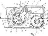
図1及び図2に示した内燃機関の配量システム用の電動モータ式調整ユニットは、いわゆる「スロットルバルブ調整ユニット」として、内燃機関により吸入される燃焼空気を制御するために使用される。このために該調整ユニットは、スロットルバルブ10として構成された調整部材11を有しており、該調整部材11は、調整軸12に相対回動不能に設けられていて、該調整軸12自体は調整器ケーシング13に回動可能に軸支されている。スロットルバルブ10はこの場合、スロットルバルブ装備短管14内に配置されており、かつ回動位置に応じて、スロットルバルブ装備短管14の大きな又は小さな内法横断面を解放する。前記スロットルバルブ装備短管14は、内燃機関に通じる吸気管内に配置されている。
【0012】
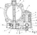
調整軸12を回動させるために、本実施例では直流モータとして構成された整流子モータ15が使用され、該整流子モータは、モータケーシング18とステータ16とロータ17とから成る完全なユニットとして、調整器ケーシング13内に収容されている(図2)。ロータ17を支持するモータ軸19には、整流子20が相対回動不能に設けられていて、該整流子20には、ブラシ保持器21に固定された2つの炭素ブラシ又は整流子ブラシ22が直径方向で圧接している。モータ軸19にはさらに、1つの駆動ピニオン23が設けられており、該駆動ピニオン23は、変速歯車装置24を介して、調整軸12に相対回動不能に配置された歯車セグメント25を駆動する。該歯車セグメント25を介しての調整軸12の調節は戻し装置26に抗して行われる。該戻し装置26は、整流子モータ15の無給電時に、予荷重のかけられたばねによりスロットルバルブ10を、いわゆる「非常空気位置(Notluftposition)」へ戻す。この非常空気位置では、内燃機関の非常運転のために充分な空気量だけが、スロットルバルブ装備短管14を介して吸入される。スロットルバルブ10の前記非常空気位置は図2に示されている。非常空気量は、図2で見てスロットルバルブ10の左側エッジに沿って該スロットルバルブ10とスロットルバルブ装備短管14との間に解放された空気流過横断面によって確定される。
【0013】
調整軸12にはセンサ27が接触結合されており、該センサ27は調整軸12の回動位置を検出し、かつ電気的な信号として制御装置に伝送する。センサ27は、支持体30に固定されていて調整軸12を半径方向に間隔を置いて包囲するセンサステータ28と、該センサステータ28によって包囲されたセンサロータ29とから成り、該センサロータは調整軸12と相対回動不能に結合されている。センサロータ29は、調整軸12に相対回動不能に設けられているスリーブ31と、該スリーブ31に固定されていて該スリーブ31から半径方向に張出す磁石32とから成っており、該磁石32は、スリーブ31とセンサステータ28との間の間隙内で回転することができる。センサステータ28は、2つの半割リング状の磁束案内片33から組合わされて1つの完全リングを形成し、かつ、直径方向に配置された2つのホールIC素子(Hall−IC)34を有しており、該ホールIC素子34は、プリント配線基板35上に配置されている。プリント配線基板35は、半割リング状のプリント配線基板部分351と、これに一体成形されていて中央から半径方向に突出継続する突出部状のプリント配線基板部分352とを有している。半割リング状のプリント配線基板部分351は、一方の半割リング状の磁束案内片33上に載置されており、かつその両自由端部に両ホールIC素子34を支持している。突出部状のプリント配線基板部分352はその自由端部に、自由にアプローチ可能な4つの接点部位36を有し、各接点部位は、プリント配線基板35の導体路(図示せず)を介してホールIC素子34と接点接続されている。センサ27のための支持体30は、スリーブ状に構成されており、かつその円筒形構造に基づいて、同時に戻し装置26のための案内部として働く。前記支持体30は、該支持体30から半径方向に張出す舌片案内部37を有し、該舌片案内部37は、互いに間隔を置いて平行に延びる2つの突出部371,372から成っている。両突出部371,372は、その自由端部で1つの横ウェブ373を介して互いに結合されており、該横ウェブ373は、両突出部371,372の下面側を延在している。プリント配線基板35を組付けた場合、突出部状のプリント配線基板部分352は、両突出部371,372の上面に位置し、かつ舌片案内部37の上に密接して延びている。舌片案内部37は、支持体30を支持プレート38に当て付けて、かつ該支持プレート38に配置されたプラグコネクタ39の差込み接点に対するセンサ27の電気的な接点接続を形成するための嵌め継ぎ手段である。プラグコネクタ39の差込み接点(図示せず)を介してセンサ37は制御装置に接続される。
【0014】
プラグコネクタ39以外に支持プレート38にはさらに、ブラシ保持器21が固定されている。図示の実施例では、ブラシ保持器21は、いわゆる「ハンマーブラシ保持器(Hammerbuerstenhalter)」として形成されており、該ハンマーブラシ保持器は、それぞれ1つの整流子ブラシ22を支持する導電性の2つの片持ち式板ばね40を有しており、両板ばね40は、一方の端部を支持プレート38内に射出成形で埋込まれており、かつ、プラグコネクタ39の差込み接点に通じる電気的な導体に接続されている。支持プレート38に沿った全ての電気的な導体は、打抜き加工された格子である打抜き格子体41(図4)により実現されている。本実施例では6本の別個の電気的な導体路411,412から成る打抜き格子体41は、支持プレート38内に共に射出成形で埋込まれているか、それとも支持プレート38内に予め形成された受容部に装嵌される。全ての導体路411,412は、一端部で、プラグコネクタ39の差込み接点の1つと接点接続されている。2本の導体路412は、ブラシ保持器21の板ばね40と接点接続されていて、ロータ17に給電する働きをしている。4本の導体路411は、屈曲された導体路区分を有して、支持プレート38に一体に成形されたシフト舌片42全体にわたって延在している。支持プレート38内に打抜き格子体41を射出成形で埋込んだ場合には、屈曲された導体路区分の上面は露出ている。同様に一方の嵌め継ぎ手段を形成するシフト舌片42は、支持体30の舌片案内部37に適合されており、かつ、支持体30と支持プレート38との接ぎ嵌め時に、舌片案内部37の突出部371,372間に挿嵌される。それと同時に、突出部状のプリント配線基板部分352において接点部位36を保持する導体路は、打抜き格子体41の導体路411の、シフト舌片42上で露出した終端区分の上に被せ嵌められる。その結果、センサ27とプラグコネクタ39との間に電気的な接続が生ぜしめられる。
【0015】
支持体30と支持プレート38が接合されると、プレハブの組立ユニットが生じ、該組立ユニット内では、構成素子つまりセンサ27及びブラシ保持器21は、プラグコネクタ39と機能的に接続されており、組立ユニットは、調整器ケーシング13内に装嵌されて位置固定されるだけでよい。組立ユニットの装嵌時に、整流子ブラシ22は、すでに調整器ケーシング13内に装嵌されている整流子モータ15の整流子20上に被せ嵌められ、かつセンサ27のスリーブ31は調整軸12の1区分を包囲する。支持プレート38には複数の固定穴43が穿設されており、該固定穴43を通して固定ねじが差込まれ、該固定ねじは、前記固定穴43に整合するように調整器ケーシング13に設けられたねじ穴に螺入可能である。組立ユニットの組付け時に、組付け公差は、シフト舌片42を舌片案内部37に沿ってシフトすることによって補正することが可能である。組付けを行なった後に、プリント配線基板35の接点部位36において、プリント配線基板35の導体路を、この導体路の下に位置正しく位置している、打抜き格子体41の導体路411の終端区分に溶接又はボンディング接合することができるので、支持体30と支持プレート38との間には、耐揺動性及び耐振動性の電気的及び機械的な結合が形成される。相応に構成すれば、支持プレート38のシフト舌片42が、固定穴43に差し通される固定ねじにより調整器ケーシング13内に支持プレート38を緊定する際に、舌片案内部37の横ウェブ373を、調整器ケーシング13に圧接し、これにより支持体30と支持プレート38との間にクランプ継手を形成することによって、前記シフト舌片42は、支持体30及び支持プレート38を機械的に位置固定するために使用され得る。また組立時に、先ず支持体30と支持プレート38とから成る組立ユニットを、整流子モータ15の上に装嵌し、次いで両者を調整器ケーシング13内に挿入することも可能である。
【0016】
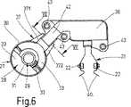
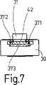
前記のスロットルバルブ調整ユニットとして構成された電動式調整ユニットは、図2では断面図で、また図1では図2の矢印Iの方向で見た側面図で示されている。但し図1では駆動ピニオン23がモータ軸19から取り外され、また歯車セグメント25が調整軸12から取り外され、かつ変速歯車装置24が除去されている。支持体30と支持プレート38とを嵌め継ぎして成る、センサ27、ブラシ保持器21及びプラグコネクタ39を装備した完全な組立ユニットが、図3において、調整器ケーシング13に組み付けられる前の状態で図示されている。但し図5ではこの組立ユニットの場合、支持体30と支持プレート38との間の嵌め継ぎ部位と、支持体30及び支持プレート38において舌片案内部37及びシフト舌片42として構成された嵌め継ぎ手段とを明示するために、プリント配線基板35は、センサ27用の支持体30から除去されている。図6は、図5の組立ユニットの平面図であり、嵌め継ぎ部位を通る断面箇所を示す線が引かれている。図7に示した嵌め継ぎ部位の断面図には、舌片案内部37の、スリーブ状の支持体30から張出している両突出部371,372が示されており、該突出部371,372は、自由端部で下面側から横ウェブ373により覆われている。さらに、支持プレート38の、前記の両突出部371,372間に受容されていて前記横ウェブ373の上に位置しているシフト舌片42が図示されている。
【0017】
図8に示した変化実施形態による、支持体30と支持プレート38とから成る組立ユニットも、同等の形式で調整ユニットの調整器ケーシング13内へ挿嵌可能である。該組立ユニットも前述の実施形態による組立ユニットに大体において合致しているので、同等の構成要素には同一符号を付した。本実施形態は、支持体30と支持プレート38とを組合せるための嵌め継ぎ手段に関して改変されているだけである。支持体30に同様に設けられてはいるが改変された両突出部44,45は、改変されていない支持プレート38に設けられたシフト舌片42に対する案内機能を有していない。つまり両突出部44,45は、支持プレート38へ装着する際に支持体30を正しく方位づける働きをするだけである。支持プレート38に一体的に組込まれた打抜き格子体41′が前記実施形態と相異している点は、4本の導体路411が、シフト舌片42上に位置する端部に、垂直上向きのピン46を支持し、該ピン46が支持プレート38から直角に突出している(図9)ことである。この際、ピン46は互いに間隔を置いて、シフト舌片42の縦軸線に対して直角方向に1列に配列されている。打抜き格子体41′は、張出したピン46を除けば、完全に支持プレート38内に射出成形で埋込まれている。
【0018】
支持体30に固定されたプリント配線基板35は、その突出部状のプリント配線基板部分352の自由端部に複数の目環47を有し、該目環47の個数は、打抜き格子体41′に設けたピン46の個数に等しい。詳細な図示は省いたが、目環47は、プリント配線基板35の各導体路ごとに1つずつ穿設した穴により形成されている。目環47は、ピン46と同様に、互いに間隔を置いて1列に配列されており、その場合の列は、突出部状のプリント配線基板部分352の縦軸線に対して直角に延びている。支持体30と支持プレート38との嵌め継ぎ時に、前記目環47がピン46に被せられる。目環47の内法の直径は、ピン46の外径よりもやや大きく選択されているので、ピン46と目環47との間に存在する遊びは、支持体30と支持プレート38との間の、制限された運動可能性を保証し、これにより調整器ケーシング13に組立ユニットを組付ける際に、場合によって発生する公差を補償することが可能になる。固定穴43により支持プレート38を調整器ケーシング13に位置固定した後に、前記ピン46は目環47と例えば鑞接されるので、耐揺動・耐揺振性の機械的及び電気的な結合が、支持体30と支持プレート38との間に得られる。ホールIC素子34は、本実施形態でも、プリント配線基板35内の導体路、目環47、ピン46及び打抜き格子体41′の導体路411を介して、プラグコネクタ39内の差込み接点と電気的に接続されている。両整流子ブラシ22は、板ばね40と打抜き格子体41′の別の2つの導体路412とを介して、プラグコネクタ39の別の2つの差込み接点と接続されている。プラグコネクタ39を介して、調整軸12の回動角度位置を検出・伝送するためのセンサ27が制御装置に接続される一方、整流子モータ15が直流電圧源に接続される。
【0019】
支持体30と支持プレート38とから成る組立ユニットを、調整軸12とモータ軸19との間に種々異なる間隔を有する調整器ケーシング13の可変的なサイズに適合させるために、突出部状のプリント配線基板部分352内に、別の、少なくとももう1列の目環47′が設けられており、該目環列は、第1列の目環47から軸方向間隔をおいて、かつ平行に配置されている。該目環47′は、目環47と同様に、プリント配線基板35の導体路内の穴によって実現されている。嵌め継ぎ時に今や、支持プレート38のシフト舌片42から突出するピン46を、選択的に最前列の目環47にか又は後列の目環47′に挿嵌することが可能になり、これによって支持体30と支持プレート38との間の間隔が変化する。
【0020】
本発明は、スロットルバルブ調整ユニットの前記実施例に限定されるものではない。例えば前記電動モータ式調整ユニットの調整部材は、内燃機関の排ガス戻し導管内に配置されていて内燃機関の燃焼空気に供給される排ガス量を調量する制御弁であってもよい。ホールIC素子をもって構成されたセンサ27に代えて、ポテンショメータとして構成された公知のセンサを使用して、調整軸12の回動位置を検出してもよい。
【図面の簡単な説明】
【図1】 伝動装置を取り外した状態で、図2に示した矢印Iの方向で見た調整ユニットの側面図である。
【図2】 調整ユニットの、図1に示した線II−IIに沿った断面図である。
【図3】 図1及び図2に示した調整ユニットの、支持体と支持プレートとから成る組立ユニットの斜視図である。
【図4】 図3に示した支持プレート内に組込まれた打抜き格子体の斜視図である。
【図5】 支持体からプリント配線基板を取り外して示した図3相当の斜視図である。
【図6】 図5に示した矢印VIの方向で見た平面図である。
【図7】 図6に示した線VII−VIIに沿った断面図である。
【図8】 変化態様による組立ユニットの図3相当の斜視図である。
【図9】 図8示した支持プレートにおける打抜き格子体の斜視図である。[0001]
The present invention relates to an electric motor type adjustment unit for a distribution system of an internal combustion engine, such as an air distribution system or a fuel distribution system, of the type as described in the superordinate concept of claim 1 .
[0002]
The electric motor type adjustment unit of the above-mentioned type which is known based on the specification of German Patent Application No. 19644169 is configured as a throttle valve adjustment unit, in which case the adjustment member is a throttle valve, The throttle valve controls the amount of air supplied to the internal combustion engine in the intake system of the internal combustion engine depending on whether the cross section of the short pipe equipped with the throttle valve is wide open or narrow open. In this throttle valve adjusting device, the support plate has a sensor configured as a potentiometer for detecting and transmitting the throttle valve position in addition to the plug connector and the brush holder. The plug connector is connected to the plug contact through a conductive and rigid thin metal plate embedded in the substrate. The support plate, fully pre-assembled with the plug connector, brush holder and sensor, is fitted into the casing, with the commutator brush fitted over the commutator of the commutator motor and the rotation of the potentiometer. The possible part is contact-coupled to the regulator shaft or throttle valve shaft. The inserted support plate is fixed in position within the casing by using screws, and is thereby coupled to the throttle valve casing in a vibration-resistant manner.
[0003]
Advantages of the Invention The electric motor type adjustment unit of the present invention includes a support plate that supports a plug connector and a brush holder, and a support member that supports a sensor for detecting the position of the adjustment member. The advantage is that a prefabricated assembly unit can be obtained in which all electrical connections between them are present. Since the support plate and the support body are not rigidly connected and are merely fitted together, it is possible to correct the assembly tolerance without problems when the assembly unit is assembled in the regulator casing. As a result, the assembly process can be automated very easily. After the assembly unit is fixed in the adjuster casing, the electrical conductors of the support and the support plate, which are contact-connected at the fitting joint, are additionally brought into contact with each other, so that the support and the support plate are connected to each other. It is also possible to form a fixed mechanical connection.
[0004]
Furthermore, the additional advantage gained by having a two-part assembly unit, that is, consisting of a support and a support plate, is usually present between the commutator motor and the adjusting shaft. Even if the design of the transmission gear transmission is different, the assembly unit can be used in its original form without modification to the adjustment unit. In the case of a transmission device of a different mode, the distance between the axes of the adjustment shaft and the motor shaft of the commutator motor extending in parallel with each other changes, and the casing size according to the change mode of the transmission device changes. Can be dealt with by appropriately shifting the fitting splice means and aligning them with each other so that the relative position of the support plate and the support is adapted to the installation space present in the regulator casing. Therefore, for differently designed transmissions, the need to pre-stock different forms of supports and support plates is also significantly reduced, which is a significant cost savings.
[0005]
By means of the constituent elements described in
[0006]
In an advantageous embodiment of the invention, the fitting means comprises a shift tongue and a tongue guide for receiving the shift tongue, one of which is the support plate and the other is the support. Is arranged. In this case, the tongue guide part is advantageously composed of two parallelprotrusions spaced apart from each other, and bothprotrusions are connected to each other via one lateral web on the lower surface side. . With this structural embodiment, the support and the support plate can be continuously changed in their relative positions and thus can be adapted with high accuracy to the set-up values in the regulator casing.
[0007]
According to an alternative embodiment of the invention, the fitting means comprises a plurality of conductive pins and a plurality of conductive eyes that surround each pin with play at the fitting site. Pins are formed on the electrical conductors of the support plate and eye rings are formed on the electrical conductors of the support body, or vice versa, pins are formed on the electrical conductors of the support body, and the eye rings are formed on the support plate The electrical conductor is formed. If the electrical conductor of the support plate is configured as a punched grid, the pins are bent at a right angle from the punched grid, particularly preferably integrally, at the end of the punched grid, When the electrical conductor of the support is configured as a conductor path of the printed wiring board, each of the above-described eye rings is formed in each conductor path as a hole. In this case, the joint between the support and the support plate is performed by inserting the pin into the ring of the printed wiring board, and the relative position between the support and the support plate is caused by the existing play. A certain degree of tolerance compensation is possible. When the pin is inserted into the eye ring, an electrical contact connection is made at the same time, which can be ensured by additional bonding or brazing. At the same time, a mechanical rigid connection is also obtained between the support and the support plate.
[0008]
In this alternative embodiment, the change in the relative position of the support and the support plate, in an advantageous embodiment of the invention, causes the plurality of eye rings to extend in a transverse direction perpendicular to the fitting seam direction. And at least one additional second ring of similar eye rings arranged in parallel with each other along the first eye ring line Obtained by arranging. Depending on the design of the transmission and the size of the regulator casing associated therewith, it is possible to insert the pins into the first row of rings or the rings of the following rows, thereby supporting It becomes possible to adapt the relative position of the body and the support plate to the casing size.
[0009]
Of course, it is also possible for the fitting means formed on the support and the support plate to have pins and eyelets on the support and support plate that can be inserted into each other together with the shift tongue and the tongue guide.
[0010]
DESCRIPTION OF EMBODIMENTS Embodiments of the present invention will be described below in detail with reference to the drawings.
[0011]
The electric motor type adjustment unit for the internal combustion engine metering system shown in FIGS. 1 and 2 is used as a so-called “throttle valve adjustment unit” for controlling the combustion air taken in by the internal combustion engine. For this purpose, the adjustment unit has an
[0012]
In order to rotate the adjusting
[0013]
A
[0014]
In addition to the
[0015]
When the
[0016]
The electric adjustment unit configured as the throttle valve adjustment unit is shown in a sectional view in FIG. 2 and in a side view seen in the direction of arrow I in FIG. However, in FIG. 1, the
[0017]
The assembly unit comprising the
[0018]
The printed
[0019]
In order to adapt the assembly unit consisting of the
[0020]
The present invention is not limited to the embodiment of the throttle valve adjustment unit. For example, the adjustment member of the electric motor type adjustment unit may be a control valve that is disposed in the exhaust gas return conduit of the internal combustion engine and regulates the amount of exhaust gas supplied to the combustion air of the internal combustion engine. Instead of the
[Brief description of the drawings]
FIG. 1 is a side view of an adjustment unit as seen in the direction of arrow I shown in FIG. 2 with a transmission device removed.
FIG. 2 is a cross-sectional view of the adjustment unit taken along line II-II shown in FIG.
3 is a perspective view of an assembly unit composed of a support and a support plate of the adjustment unit shown in FIGS. 1 and 2. FIG.
4 is a perspective view of a punched grid body incorporated in the support plate shown in FIG. 3. FIG.
FIG. 5 is a perspective view corresponding to FIG. 3 with the printed wiring board removed from the support.
6 is a plan view seen in the direction of an arrow VI shown in FIG. 5. FIG.
7 is a cross-sectional view taken along line VII-VII shown in FIG.
FIG. 8 is a perspective view corresponding to FIG. 3 of an assembly unit according to a variation.
9 is a perspective view of a punched lattice body in the support plate shown in FIG. 8. FIG.
Claims (18)
Translated fromJapaneseセンサ(27)が支持体(30)に配置されており、該支持体(30)および支持プレート(38)には、該支持体(30)と支持プレート(38)とを結合するための互いに対応した嵌め継ぎ手段が構成されており、
嵌め継ぎ手段が、支持体(30)と支持プレート(38)とを種々異なる相対位置で互いに並べて配置することが可能であるように構成されており、
嵌め継ぎ手段が、嵌め継ぎ部位において支持体(30)と支持プレート(38)との相対的なシフト運動を可能にするように構成されており、かつ
嵌め継ぎ手段が、シフト舌片(42)と、該シフト舌片(42)を受容する舌片案内部(37)とを有しており、その内の一方が支持プレート(38)に、他方が支持体(30)に配置されていることを特徴とする、内燃機関の配量システムのための電動モータ式の調整ユニット。An adjustment unit of an electric motor type for a distribution system of an internal combustion engine, comprising an adjuster casing (13) and an adjuster member (11) rotatably supported in the adjuster casing (13). An adjusting shaft (12) to be operated, and a commutator motor (15) coupled to the adjusting shaft (12) is provided to rotate the adjusting shaft (12). The commutator motor (15) has a commutator (20) that is mounted on the motor shaft (19) so as not to be relatively rotatable, and a commutator brush (22) that is in pressure contact with the commutator (20). And a sensor (27) for detecting the rotational position of the adjusting shaft (12) and a support plate (38) that can be fixed in the adjuster casing (13). One of the plates (38) has the commutator brush ( 2) in which the brush holder (21) holding the plug connector (39) for electrically connecting the brush holder (21) and the sensor (27) is arranged on the other side ,
Sensor (27) is arranged on a support(30), said the support (30) and the support plate (38), said support (30) and the support plate (38) and each other for coupling the Corresponding fitting means are configured,
The fitting means is configured such that the support (30) and the support plate (38) can be arranged side by side in different relative positions,
The fitting means is configured to allow relative shifting movement of the support (30) and the support plate (38) at the fitting joint; and
The fitting joint means has a shift tongue (42) and a tongue guide portion (37) for receiving the shift tongue (42), one of which is on the support plate (38) and the other. Is arranged on a support (30), an electric motor type adjustment unit for a distribution system of an internal combustion engine.
Applications Claiming Priority (2)
| Application Number | Priority Date | Filing Date | Title |
|---|---|---|---|
| DE10112427ADE10112427A1 (en) | 2001-03-15 | 2001-03-15 | Electric motor actuator unit for internal combustion engine comprises fuel or air feed system with sensor mounted on the bearer |
| PCT/DE2002/000893WO2002075135A1 (en) | 2001-03-15 | 2002-03-13 | Electromotive actuating unit for a metering system of an internal combustion engine |
Publications (2)
| Publication Number | Publication Date |
|---|---|
| JP2004518876A JP2004518876A (en) | 2004-06-24 |
| JP4418629B2true JP4418629B2 (en) | 2010-02-17 |
Family
ID=7677542
Family Applications (1)
| Application Number | Title | Priority Date | Filing Date |
|---|---|---|---|
| JP2002573512AExpired - Fee RelatedJP4418629B2 (en) | 2001-03-15 | 2002-03-13 | Electric motor type adjustment unit for a distribution system of an internal combustion engine |
Country Status (5)
| Country | Link |
|---|---|
| US (1) | US6866018B2 (en) |
| EP (1) | EP1370756B1 (en) |
| JP (1) | JP4418629B2 (en) |
| DE (2) | DE10112427A1 (en) |
| WO (1) | WO2002075135A1 (en) |
Families Citing this family (10)
| Publication number | Priority date | Publication date | Assignee | Title |
|---|---|---|---|---|
| EP1270907A1 (en)* | 2000-04-05 | 2003-01-02 | Hitachi, Ltd. | Throttle device and throttle sensor of internal combustion engine |
| JP3948016B2 (en)* | 2002-06-27 | 2007-07-25 | 株式会社デンソー | Throttle device |
| DE10256831A1 (en) | 2002-12-04 | 2004-06-24 | Siemens Ag | Carrier part for commutator brushes of an electric motor |
| US7032569B2 (en)* | 2003-05-08 | 2006-04-25 | Aisan Kogyo Kabushiki Kaisha | Throttle control devices |
| DE10353432B4 (en)* | 2003-11-15 | 2009-07-09 | Pierburg Gmbh | Contact unit |
| DE102004059171A1 (en)* | 2004-12-08 | 2006-06-14 | Siemens Ag | Subunit for actuating a rotatably mounted shaft whose current angle of rotation is to be continuously detected |
| CN102072489B (en)* | 2011-02-25 | 2012-07-04 | 凯明企业有限公司 | burner |
| ITBO20120680A1 (en)* | 2012-12-18 | 2014-06-19 | Borghi S P A | AUTOMATIC PUNCHING MACHINE TO PRODUCE BRUSHES AND METHOD FOR PRODUCING AUTOMATIC BRUSHES FOR PUNCHING |
| US10064514B2 (en)* | 2013-12-06 | 2018-09-04 | Nestec S.A. | Handling device with movable capsule ejector |
| US11608890B2 (en)* | 2018-05-01 | 2023-03-21 | Schaeffler Technologies AG & Co. KG | Electro-mechanical park lock actuator |
Family Cites Families (11)
| Publication number | Priority date | Publication date | Assignee | Title |
|---|---|---|---|---|
| JPS61279742A (en)* | 1985-06-05 | 1986-12-10 | Nippon Denso Co Ltd | Throttle valve opening detector for vehicles |
| DE4102562A1 (en)* | 1991-01-29 | 1992-07-30 | Thomson Brandt Gmbh | METHOD AND CIRCUIT FOR AN AUTOMATIC, HIGH-PRECISION FREQUENCY TUNING |
| IT1259443B (en)* | 1992-10-29 | 1996-03-18 | Weber Srl | AIR SUPPLY DEVICE FOR AN INTERNAL COMBUSTION ENGINE. |
| DE19644169A1 (en)* | 1996-10-24 | 1998-04-30 | Mannesmann Vdo Ag | Load adjustment device |
| JP3404254B2 (en)* | 1997-05-07 | 2003-05-06 | 株式会社日立製作所 | Engine throttle device |
| JP3112074B2 (en)* | 1998-01-23 | 2000-11-27 | 株式会社日立製作所 | Electronically controlled throttle valve device for internal combustion engine |
| EP1270907A1 (en)* | 2000-04-05 | 2003-01-02 | Hitachi, Ltd. | Throttle device and throttle sensor of internal combustion engine |
| DE10019117A1 (en)* | 2000-04-18 | 2001-12-13 | Mannesmann Vdo Ag | Throttle valve actuator |
| US6347613B1 (en)* | 2000-07-05 | 2002-02-19 | Visteon Global Technologies, Inc. | Electronic throttle control mechanism with integrated modular construction |
| US6789526B2 (en)* | 2001-02-08 | 2004-09-14 | Denso Corporation | Apparatus for controlling throttle valve and manufacturing method for the same and motor |
| DE10137454A1 (en)* | 2001-08-02 | 2003-02-20 | Siemens Ag | throttle body |
- 2001
- 2001-03-15DEDE10112427Apatent/DE10112427A1/ennot_activeWithdrawn
- 2002
- 2002-03-13USUS10/276,268patent/US6866018B2/ennot_activeExpired - Fee Related
- 2002-03-13JPJP2002573512Apatent/JP4418629B2/ennot_activeExpired - Fee Related
- 2002-03-13EPEP02729787Apatent/EP1370756B1/ennot_activeExpired - Lifetime
- 2002-03-13WOPCT/DE2002/000893patent/WO2002075135A1/enactiveIP Right Grant
- 2002-03-13DEDE50209010Tpatent/DE50209010D1/ennot_activeExpired - Lifetime
Also Published As
| Publication number | Publication date |
|---|---|
| WO2002075135A1 (en) | 2002-09-26 |
| US20040079331A1 (en) | 2004-04-29 |
| DE50209010D1 (en) | 2007-02-01 |
| EP1370756A1 (en) | 2003-12-17 |
| JP2004518876A (en) | 2004-06-24 |
| US6866018B2 (en) | 2005-03-15 |
| DE10112427A1 (en) | 2002-09-19 |
| EP1370756B1 (en) | 2006-12-20 |
Similar Documents
| Publication | Publication Date | Title |
|---|---|---|
| US6854443B2 (en) | Assembly for electronic throttle control with non-contacting position sensor | |
| JP3842336B2 (en) | Throttle valve adjustment unit | |
| JP5066142B2 (en) | Motor-driven throttle valve device with inductive throttle sensor and inductive throttle sensor for detecting the rotation angle of the throttle shaft of the motor-driven throttle valve device | |
| JP4418629B2 (en) | Electric motor type adjustment unit for a distribution system of an internal combustion engine | |
| US8534641B2 (en) | Connecting element and associated fluid assembly | |
| US7191754B2 (en) | Position sensor apparatus and method | |
| KR101213776B1 (en) | Control and interconnection system for an apparatus | |
| US7501929B2 (en) | Actuator with integral position sensor | |
| JPWO2008102482A1 (en) | Motor terminal structure | |
| EP1096235B1 (en) | Magnetic rotation sensor | |
| JP4604091B2 (en) | Electronic equipment | |
| JP3394407B2 (en) | Motor drive | |
| CN112424460B (en) | Electronically controlled throttle device | |
| US6373212B1 (en) | Electric connector | |
| KR20000049223A (en) | Load shifting device | |
| US20030084862A1 (en) | Magnet actuator for a camshaft controller | |
| US6227871B1 (en) | Device for contact-connecting a circuit board | |
| JP4217941B2 (en) | Fuel injection apparatus and adjustment method thereof | |
| EP1674695B1 (en) | Assembly for electronic throttle control with position sensor | |
| CN210142963U (en) | Motor unit | |
| CN101495733A (en) | Idle air control valve wire stress relief feature and assembly aids | |
| CN120487358A (en) | Turbocharger electronic actuator | |
| JP2665252B2 (en) | Fuel supply device | |
| KR20060050117A (en) | Electrical drive unit comprising at least two electrical component carrier and its manufacturing method | |
| HK1059342B (en) | Motor-sensor-system |
Legal Events
| Date | Code | Title | Description |
|---|---|---|---|
| A621 | Written request for application examination | Free format text:JAPANESE INTERMEDIATE CODE: A621 Effective date:20050314 | |
| RD03 | Notification of appointment of power of attorney | Free format text:JAPANESE INTERMEDIATE CODE: A7423 Effective date:20071211 | |
| A131 | Notification of reasons for refusal | Free format text:JAPANESE INTERMEDIATE CODE: A131 Effective date:20080104 | |
| A601 | Written request for extension of time | Free format text:JAPANESE INTERMEDIATE CODE: A601 Effective date:20080404 | |
| A602 | Written permission of extension of time | Free format text:JAPANESE INTERMEDIATE CODE: A602 Effective date:20080411 | |
| A521 | Request for written amendment filed | Free format text:JAPANESE INTERMEDIATE CODE: A523 Effective date:20080415 | |
| A131 | Notification of reasons for refusal | Free format text:JAPANESE INTERMEDIATE CODE: A131 Effective date:20081114 | |
| A601 | Written request for extension of time | Free format text:JAPANESE INTERMEDIATE CODE: A601 Effective date:20090213 | |
| A602 | Written permission of extension of time | Free format text:JAPANESE INTERMEDIATE CODE: A602 Effective date:20090220 | |
| A601 | Written request for extension of time | Free format text:JAPANESE INTERMEDIATE CODE: A601 Effective date:20090316 | |
| A602 | Written permission of extension of time | Free format text:JAPANESE INTERMEDIATE CODE: A602 Effective date:20090324 | |
| A521 | Request for written amendment filed | Free format text:JAPANESE INTERMEDIATE CODE: A523 Effective date:20090410 | |
| TRDD | Decision of grant or rejection written | ||
| A01 | Written decision to grant a patent or to grant a registration (utility model) | Free format text:JAPANESE INTERMEDIATE CODE: A01 Effective date:20091030 | |
| A01 | Written decision to grant a patent or to grant a registration (utility model) | Free format text:JAPANESE INTERMEDIATE CODE: A01 | |
| A61 | First payment of annual fees (during grant procedure) | Free format text:JAPANESE INTERMEDIATE CODE: A61 Effective date:20091130 | |
| R150 | Certificate of patent or registration of utility model | Free format text:JAPANESE INTERMEDIATE CODE: R150 | |
| FPAY | Renewal fee payment (event date is renewal date of database) | Free format text:PAYMENT UNTIL: 20121204 Year of fee payment:3 | |
| FPAY | Renewal fee payment (event date is renewal date of database) | Free format text:PAYMENT UNTIL: 20121204 Year of fee payment:3 | |
| FPAY | Renewal fee payment (event date is renewal date of database) | Free format text:PAYMENT UNTIL: 20131204 Year of fee payment:4 | |
| R250 | Receipt of annual fees | Free format text:JAPANESE INTERMEDIATE CODE: R250 | |
| LAPS | Cancellation because of no payment of annual fees |