JP4418285B2 - Endoscope balloon control device - Google Patents
Endoscope balloon control deviceDownload PDFInfo
- Publication number
- JP4418285B2 JP4418285B2JP2004115847AJP2004115847AJP4418285B2JP 4418285 B2JP4418285 B2JP 4418285B2JP 2004115847 AJP2004115847 AJP 2004115847AJP 2004115847 AJP2004115847 AJP 2004115847AJP 4418285 B2JP4418285 B2JP 4418285B2
- Authority
- JP
- Japan
- Prior art keywords
- balloon
- endoscope
- predetermined
- flow rate
- pump
- Prior art date
- Legal status (The legal status is an assumption and is not a legal conclusion. Google has not performed a legal analysis and makes no representation as to the accuracy of the status listed.)
- Expired - Fee Related
Links
- 230000002159abnormal effectEffects0.000claimsdescription42
- 238000003780insertionMethods0.000claimsdescription32
- 230000037431insertionEffects0.000claimsdescription32
- 230000005856abnormalityEffects0.000claimsdescription26
- 230000008859changeEffects0.000claimsdescription5
- 238000007689inspectionMethods0.000description43
- 238000010586diagramMethods0.000description13
- 238000000034methodMethods0.000description12
- 230000002265preventionEffects0.000description8
- 238000001727in vivoMethods0.000description6
- 239000000463materialSubstances0.000description6
- 230000002093peripheral effectEffects0.000description5
- 238000012790confirmationMethods0.000description4
- 230000000968intestinal effectEffects0.000description4
- 238000012360testing methodMethods0.000description4
- 238000003384imaging methodMethods0.000description3
- 238000005259measurementMethods0.000description3
- 238000012545processingMethods0.000description3
- 238000004891communicationMethods0.000description2
- 230000008602contractionEffects0.000description2
- 210000001035gastrointestinal tractAnatomy0.000description2
- 239000007788liquidSubstances0.000description2
- 230000008569processEffects0.000description2
- 230000009471actionEffects0.000description1
- 230000004397blinkingEffects0.000description1
- 238000009530blood pressure measurementMethods0.000description1
- 230000003247decreasing effectEffects0.000description1
- 230000007547defectEffects0.000description1
- 230000006870functionEffects0.000description1
- 230000006872improvementEffects0.000description1
- 210000000936intestineAnatomy0.000description1
- 238000004519manufacturing processMethods0.000description1
- 230000004044responseEffects0.000description1
- 230000000007visual effectEffects0.000description1
Images


Landscapes
- Endoscopes (AREA)
Description
Translated fromJapanese本発明は、内視鏡バルーン制御装置に関し、特に、ポンプの所定の管路への送気流量を調整する流量調整手段を制御しつつ、内視鏡に取り付けられるバルーンの異常を判定することのできる内視鏡バルーン制御装置に関するものである。 The present invention relates to an endoscope balloon control device, and more particularly, to determine an abnormality of a balloon attached to an endoscope while controlling a flow rate adjusting means for adjusting an air flow rate to a predetermined pipe line of a pump. The present invention relates to an endoscopic balloon control device that can be used.
従来より、内視鏡は医療分野等において広く用いられている。特に、医療分野における内視鏡は、術者が被検体である生体内の検査、観察等の処置を行うという用途において主に用いられている。そのため、内視鏡による生体内の検査、観察等を行う際に、術者および生体に対する負担を軽減するという目的において、内視鏡の生体への挿入性および内視鏡の生体内での操作性の向上を図る装置の提案がこれまでに数多くなされている。 Conventionally, endoscopes have been widely used in the medical field and the like. In particular, endoscopes in the medical field are mainly used for applications in which an operator performs a treatment such as in-vivo examination and observation of a subject. Therefore, in order to reduce the burden on the operator and the living body when performing in-vivo inspection and observation with the endoscope, the insertion property of the endoscope into the living body and the operation of the endoscope in the living body are reduced. Many proposals have been made so far for improving the performance.
このような装置としては、例えば、特許文献1において提案されている内視鏡挿入補助用バルーン付きチューブ、および特許文献2において提案されている内視鏡装置といった装置がある。 Examples of such an apparatus include apparatuses such as a tube with an endoscope insertion assisting balloon proposed in
特許文献1において提案されている内視鏡挿入補助用バルーン付きチューブは、内視鏡の先端に取り付けられる内視鏡先端バルーンと、内視鏡に取り付けられるチューブ本体と、チューブ本体の先端に設けられたチューブ先端バルーンとを具備している。 A tube with an endoscope insertion assisting balloon proposed in
また、特許文献2において提案されている内視鏡装置は、内視鏡本体の先端に取り付けられる本体固定用バルーンと、内視鏡に取り付けられるスライディングチューブと、スライディングチューブの先端外周部に取り付けられたチューブ固定用バルーンとを具備している。 In addition, the endoscope apparatus proposed in
前記特許文献1および前記特許文献2内に開示されている発明においては、共に内視鏡および内視鏡に取り付けるチューブにそれぞれ1つずつバルーンが取り付けられており、該バルーンにより、内視鏡の生体への挿入性および内視鏡の生体内での操作性の向上が図られている。
内視鏡の挿入性および操作性の向上を目的として用いられるバルーンは、様々な材質で形成された、様々な容量を持つものがあり、術者が生体に対して行う処置の内容、術者が処置の際に用いる内視鏡の種類、および生体の個体差等によって使い分けられていることが一般的である。 Balloons used for the purpose of improving the insertability and operability of endoscopes are made of various materials and have various capacities. Are generally used depending on the type of endoscope used in the treatment and individual differences of the living body.
そのため、例えば、生体に対して処置を行う現場においては、バルーンの交換を何度も行いながら処置を行う場合も想定される。この場合、バルーンの交換の度に、交換用のバルーンに対し、生体内における固定不良が起こる可能性を、術者および術者の補助者等が生体外で確認を行う必要が生じ、結果的に生体に対する処置時間が長くなるという課題がある。 Therefore, for example, in the field where treatment is performed on a living body, it is assumed that the treatment is performed while the balloon is exchanged many times. In this case, every time the balloon is replaced, it is necessary for the surgeon and the assistant of the surgeon to check the possibility that improper fixation in the living body will occur in vivo. In addition, there is a problem that the treatment time for a living body becomes long.
しかし、前記特許文献1内に開示されている発明においては、所定の材質で形成されたバルーンにおける最適な拡張圧のみが記載されているのみであり、生体内における固定不良が起こる可能性を生体外で確認する手段については記載されておらず、前記課題に対する提案はなされていない。 However, in the invention disclosed in
また、前記特許文献2内に開示されている発明においては、バルーン内の圧力を最適な状態に制御する制御手段は具備しているが、該制御手段は、生体内における固定不良が起こる可能性を生体外で確認する手段を有しておらず、前記特許文献1内に開示されている発明と同様に、前記課題に対する提案はなされていない。 The invention disclosed in
本発明は、前記した点に鑑みてなされたものであり、内視鏡に取り付けられるバルーン管路の異常を、生体に対して処置を行う現場において、簡便かつ自動的に判定することのできる内視鏡バルーン制御装置を提供することを目的としている。 The present invention has been made in view of the above points, and is capable of easily and automatically determining an abnormality in a balloon duct attached to an endoscope at a site where treatment is performed on a living body. An object of the present invention is to provide an endoscopic balloon control device.
本発明における内視鏡バルーン制御装置は、内視鏡に用いられるバルーンに接続される所定の管路に対し空気の送気を行うポンプと、前記所定の管路の内圧を測定する圧力測定手段と、前記ポンプの前記所定の管路に対する送気流量を調整する流量調整手段と、前記流量調整手段を制御することによって、前記ポンプの前記所定の管路への送気流量を変化させて前記所定の管路の内圧値を所定の圧力値とした後、第1の時間および第2の時間において前記圧力測定部が測定した前記所定の管路の内圧値を取得し、かつ、前記第1の時間における前記所定の管路の第1の内圧値と第2の時間における前記所定の管路の第2の内圧値との差の絶対値が所定の閾値を超える場合においては、前記バルーンが異常であることを判定する制御手段と、前記制御手段の判定結果に基づき、前記所定の管路の異常を告知する異常状態告知手段とを具備している。 An endoscope balloon control device according to the present invention includes a pump for supplying air to a predetermined pipe line connected to a balloon used in the endoscope, and a pressure measuring unit for measuring an internal pressure of the predetermined pipe line And a flow rate adjusting means for adjusting an air supply flow rate to the predetermined pipe line of the pump, and by controlling the flow rate adjusting means, the air flow rate to the predetermined pipe line of the pump is changed to change the flow rate. After the internal pressure value of the predetermined pipeline is set to the predetermined pressure value, the internal pressure value of the predetermined pipeline measured by the pressure measuring unit at the first time and the second time is acquired, and the first When the absolute value of the difference between the first internal pressure value of the predetermined pipeline at the time of time and the second internal pressure value of the predetermined pipeline at the second time exceeds a predetermined threshold, the balloon Control means for judging that there is an abnormality, Based on the determination result of the control means, and an abnormal state notification means for notifying an abnormality of the predetermined line.
本発明は、生体に対して処置を行う現場において、術者および術者の補助者等が、簡便かつ自動的に、内視鏡用バルーンおよびオーバーチューブ用バルーンにおける気密不良等の異常を確認することができるような内視鏡バルーン制御装置を提供できる。 According to the present invention, an operator, an assistant of an operator, and the like confirm an abnormality such as a poor airtightness in an endoscope balloon and an overtube balloon in a field where a treatment is performed on a living body easily and automatically. It is possible to provide an endoscopic balloon control apparatus that can perform such a process.
以下、図面を参照して本発明の実施の形態を説明する。 Embodiments of the present invention will be described below with reference to the drawings.
まず、図1および図10から図16を用いて、本実施形態に係る内視鏡バルーン制御装置が用いられる、内視鏡システムについて説明を行う。 First, an endoscope system in which the endoscope balloon control device according to the present embodiment is used will be described with reference to FIGS. 1 and 10 to 16.
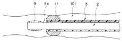
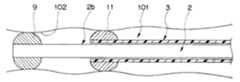
図1は、内視鏡システムにおいて、本実施形態に係る内視鏡バルーン制御装置が用いられた内視鏡システムの構成図である。図10は、生体内に内視鏡が挿入された状態を説明するための説明図である。図11は、オーバーチューブ用バルーンを拡張させ、オーバーチューブを生体内に固定した状態を示す図である。図12は、オーバーチューブが生体内に固定された際に、内視鏡の挿入部のみを所定の距離だけ前進させた状態を示す図である。図13は、内視鏡の挿入部のみを所定の距離だけ前進させた後、内視鏡用バルーンを拡張させて内視鏡の挿入部を生体内に固定した状態を示す図である。図14は、内視鏡の挿入部が生体内に固定された状態で、オーバーチューブ用バルーンを収縮させた状態を示す図である。図15は、内視鏡の挿入部が生体内に固定された際に、オーバーチューブのみを所定の距離だけ前進させた状態を示す図である。図16は、オーバーチューブを所定の距離だけ前進させた後、再びオーバーチューブ用バルーンを拡張させ、オーバーチューブを生体内に固定した状態を示す図である。 FIG. 1 is a configuration diagram of an endoscope system in which an endoscope balloon control device according to the present embodiment is used in an endoscope system. FIG. 10 is an explanatory diagram for explaining a state in which the endoscope is inserted into the living body. FIG. 11 is a diagram illustrating a state where the overtube balloon is expanded and the overtube is fixed in the living body. FIG. 12 is a diagram illustrating a state in which only the insertion portion of the endoscope is advanced by a predetermined distance when the overtube is fixed in the living body. FIG. 13 is a diagram illustrating a state in which only the insertion portion of the endoscope is advanced by a predetermined distance, and then the endoscope balloon is expanded to fix the insertion portion of the endoscope in the living body. FIG. 14 is a diagram illustrating a state in which the overtube balloon is deflated in a state where the insertion portion of the endoscope is fixed in the living body. FIG. 15 is a diagram illustrating a state in which only the overtube is advanced by a predetermined distance when the insertion portion of the endoscope is fixed in the living body. FIG. 16 is a view showing a state in which the overtube is expanded again by advancing the overtube by a predetermined distance, and the overtube is fixed in the living body.
内視鏡システム1は、内視鏡2と、光源装置4と、ビデオプロセッサ5と、モニター6と、内視鏡バルーン制御装置7とからなる。また、内視鏡2は、操作部2aと、挿入部2bと、ユニバーサルコード2cとからなる。内視鏡2の挿入部2bの外周部の先端部には、内視鏡用バルーン9が取り付けられている。外周部の内視鏡用バルーン9と操作部2aとに挟まれる部分には、オーバーチューブ3が、挿入部2bを挿通するように取り付けられている。 The
内視鏡用バルーン9は、内部に対する送気により所定の大きさまで拡張できるような材質で形成されており、挿入部2bの内周部の一部に設けられた、空気供給チューブ10と連通している。空気供給チューブ10は、操作部2aの一部に設けられたコネクタ2dと、そのコネクタ2dと接続されたコネクタ13aとを介し、第1送気チューブである内視鏡用バルーン送気チューブ13と連通している。また、内視鏡用バルーン送気チューブ13は、一端にコネクタ13aを有し、他端にコネクタ13bを有する。内視鏡用バルーン送気チューブ13の他端側のコネクタ13bは、内視鏡バルーン制御装置7のコネクタ7aに接続される。なお、コネクタ13bとコネクタ7aとの接続により、内視鏡用バルーン送気チューブ13の内部の気密が保たれる構造となっている。さらに、同様に、コネクタ2dとコネクタ13aとの接続により、空気供給チューブ10と内視鏡用バルーン送気チューブ13の内部の気密が保たれる構造となっている。 The
オーバーチューブ3は、先端部に設けられたオーバーチューブ用バルーン11と、オーバーチューブ用バルーン11に連通する空気供給チューブ12とからなる。オーバーチューブ用バルーン11は、内部に対する送気により所定の大きさまで拡張できるような材質で形成されている。空気供給チューブ12は、内視鏡2の外径よりも若干大きな内径および内視鏡2と略同様の可撓性を有し、オーバーチューブ3の一部に設けられたコネクタ3aと、そのコネクタ3aと接続されたコネクタ14aを介し、第2送気チューブであるオーバーチューブ用バルーン送気チューブ14と連通している。また、オーバーチューブ用バルーン送気チューブ14は、一端にコネクタ14aを有し、他端にコネクタ14bを有する。内視鏡用バルーン送気チューブ14の他端側のコネクタ14bは、内視鏡バルーン制御装置7のコネクタ7bに接続される。なお、コネクタ14bとコネクタ7bとの接続により、オーバーチューブ用バルーン送気チューブ14の内部の気密が保たれる構造となっている。さらに、同様に、コネクタ3aとコネクタ14aとの接続により、空気供給チューブ12とオーバーチューブ用バルーン送気チューブ14の内部の気密が保たれる構造となっている。 The
光源装置4は外部にコネクタ4aを有し、コネクタ4aは内視鏡2のユニバーサルコード2cと着脱自在に接続される構造となっている。ビデオプロセッサ5は、ユニバーサルコード2cより分岐した接続ケーブル4bと着脱自在に接続される構造となっている。また、ビデオプロセッサ5は、接続ケーブル5aを介してモニター6に接続されている。 The
リモートコントローラ8は、接続ケーブル8aと、コネクタ7cとを介して内視鏡バルーン制御装置7に接続されており、内視鏡バルーン制御装置7の操作を行うための図示しないスイッチが設けられている。 The
内視鏡システム1を用いて術者が生体内の検査、観察等を行う際には、まず、挿入部2bを生体内における検査、観察等を行う部位まで挿入する必要があるが、術者が生体に対して行う処置の内容、術者が処置の際に用いる内視鏡の種類、および生体の個体差等により、挿入部2bを該部位まで挿入することが難しい場合がある。その場合、内視鏡用バルーン9およびオーバーチューブ用バルーン11の拡張および収縮を繰り返して行うことで、挿入性および挿入後の生体内における操作性を向上させることができる。 When an operator performs in-vivo examination and observation using the
その方法としては、まず、図10に示すように、内視鏡用バルーン9およびオーバーチューブ用バルーン11を十分収縮させた状態で、術者は、挿入部2bの先端部を生体内である腸管101に挿入する。次に、挿入部2bの挿入が困難な部位にさしかかった場合、術者は、リモートコントローラ8に設けられた図示しないスイッチを操作し、内視鏡バルーン制御装置7に対し、オーバーチューブ用バルーン11を拡張させるための信号を送信する。その信号を受信した内視鏡バルーン制御装置7は、オーバーチューブ用バルーン送気チューブ14と、空気供給チューブ12とを介してオーバーチューブ用バルーン11に空気を送気し、図11に示すように、オーバーチューブ用バルーン11を拡張させる。その後、オーバーチューブ3が、オーバーチューブ用バルーン11により腸管101の外周部である腸壁102で固定されている該状態において、図12に示すように、術者は、挿入部2bのみをオーバーチューブ用バルーン11からスライドさせて、所定の距離前進させる。挿入部2bを該所定の距離だけ前進させた場合において、術者は、リモートコントローラ8に設けられた図示しないスイッチを操作し、内視鏡バルーン制御装置7に対し、内視鏡用バルーン9を拡張させるための信号を送信する。その信号を受信した内視鏡バルーン制御装置7は、オーバーチューブ用バルーン送気チューブ13と、空気供給チューブ10とを介して内視鏡用バルーン9に空気を送気し、図13に示すように、内視鏡用バルーン9を拡張させる。内視鏡用バルーン9が所定の大きさまで拡張した後、術者は、今度はリモートコントローラ8に設けられた図示しないスイッチを操作し、内視鏡バルーン制御装置7に対し、オーバーチューブ用バルーン11を収縮させるための信号を送信する。その信号を受信した内視鏡バルーン制御装置7は、装置内部に設けられた図示しない管路の一部を開放することで、前記操作によってオーバーチューブ用バルーン11に送気した空気を装置外部に放出し、図14に示すように、オーバーチューブ用バルーン11を収縮させる。その後、挿入部2bが内視鏡用バルーン9により腸壁102で固定されている該状態において、図15に示すように、術者は、挿入部2bを前進させた前記所定の距離だけオーバーチューブ3を前進させる。さらに深部に挿入部2bを前進させたい場合には、図16に示すように、術者は、再びオーバーチューブ用バルーン11を拡張させ、オーバーチューブ3を腸壁102に固定させた上で、リモートコントローラ8に設けられた図示しないスイッチを操作し、内視鏡用バルーン9を収縮させて図11の状態とする。これ以降は、図11から図16を参照しつつ説明を行った前記の方法を繰り返し行うことで、挿入部2bを深部に前進させることができる。 As the method, first, as shown in FIG. 10, in a state where the
そのようにして挿入部2bを検査、観察等を行いたい部位である被撮像部位まで挿入した後、術者は、光源装置4が有する図示しない光源から、ユニバーサルコード2c等を介して該部位に所定の光量の光を照射させる。被撮像部位が反射した光による画像情報は、光源装置4を介してビデオプロセッサ5に送信され、ビデオプロセッサ5の内部に設けられた図示しない信号処理回路により信号処理が行われ、モニター6に被撮像部位の画像として表示する。よって、術者は、被撮像部位の検査、観察等を行うことができる。 After inserting the
次に、本実施形態に係る内視鏡バルーン制御装置について説明を行う。図2から図8は、本実施形態に係るものである。図2は、本実施形態に係る内視鏡バルーン制御装置の接続構成図である。図3は、本実施形態に係る内視鏡バルーン制御装置の内部構成を示したブロック図である。図4は、本実施形態に係る内視鏡バルーン制御装置の制御内容を示すフローチャートである。図5は、図4のフローチャートにおいて、本実施形態に係る内視鏡バルーン制御装置が有するポンプの最小流量設定において異常調整終了通知と判定される場合の、管路の内圧と送気時間との関係を示したグラフである。図6は、図4のフローチャートにおいて、本実施形態に係る内視鏡バルーン制御装置が有するポンプの最大流量設定において異常調整終了通知と判定される場合の、管路の内圧と送気時間との関係を示したグラフである。図7は、図4のフローチャートにおいて、本実施形態に係る内視鏡バルーン制御装置が有するポンプの流量設定を最小流量設定から最大流量設定に変化させても異常が確認されなかった場合の、管路の内圧と送気時間との関係を示したグラフである。図8は、図4のフローチャートにおいて、内視鏡バルーン制御装置が有するポンプの流量設定を調整後流量設定とした後に、管路の内圧を略平衡状態となる所定の内圧値として管路の内圧の変化を確認する場合の、管路の内圧と送気時間との関係を示したグラフである。 Next, the endoscope balloon control device according to the present embodiment will be described. 2 to 8 relate to this embodiment. FIG. 2 is a connection configuration diagram of the endoscope balloon control device according to the present embodiment. FIG. 3 is a block diagram showing an internal configuration of the endoscope balloon control device according to the present embodiment. FIG. 4 is a flowchart showing the control contents of the endoscope balloon control device according to the present embodiment. FIG. 5 is a flow chart of FIG. 4 showing the relationship between the internal pressure of the pipeline and the air supply time when it is determined that the abnormal adjustment end notification is made in the minimum flow rate setting of the pump of the endoscope balloon control device according to the present embodiment. It is the graph which showed the relationship. FIG. 6 is a flow chart of FIG. 4 showing the relationship between the internal pressure of the pipe line and the air supply time when it is determined that the abnormal adjustment end notification is made at the maximum flow rate setting of the pump of the endoscope balloon control device according to this embodiment. It is the graph which showed the relationship. FIG. 7 is a flowchart in the case where no abnormality is confirmed even if the flow rate setting of the pump of the endoscope balloon control device according to the present embodiment is changed from the minimum flow rate setting to the maximum flow rate setting in the flowchart of FIG. It is the graph which showed the relationship between the internal pressure of a road, and air supply time. FIG. 8 is a flow chart of FIG. 4, in which the internal pressure of the pipeline is set as a predetermined internal pressure value at which the internal pressure of the pipeline is in a substantially equilibrium state after the flow rate setting of the pump of the endoscope balloon control device is set to the adjusted flow rate setting. It is the graph which showed the relationship between the internal pressure of a pipe line, and the air supply time when confirming the change of this.
内視鏡バルーン制御装置7は、コネクタ7aと、コネクタ7bと、コネクタ7cと、逆流防止用タンク15と、圧力表示器16と、電源スイッチ17と、検査スイッチ18と、異常状態告知手段である第1LED18aと、同じく異常状態告知手段である第2LED18bとを外装表面上に有する。 The endoscope
コネクタ7aは、内視鏡用バルーン送気チューブ13の一端に設けられたコネクタ13bに接続され、接続により気密が保たれる構造となっている。内視鏡用バルーン送気チューブ13の他端に設けられたコネクタ13aは、空気供給チューブ10の一端に設けられたコネクタ2dに接続され、接続により気密が保たれる構造となっている。さらに、コネクタ7aは、管路を介して第1逆流防止用タンク15aと連通している。第1逆流防止用タンク15aは、内視鏡バルーン制御装置7の内部に設けられた第1ポンプ33aから吸気を行う際に、内視鏡バルーン制御装置7側である装置内に液体が侵入することを防止するために設けられており、管路を介して圧力測定手段である第1圧力センサ35aと連通している。第1圧力表示器16aは、圧力測定手段である第1圧力センサ35aが内視鏡用バルーン9に連通する管路の内圧を基に測定した、内視鏡用バルーン9の内圧値の表示を行う。 The connector 7a is connected to a connector 13b provided at one end of the balloon
コネクタ7bは、オーバーチューブ用バルーン送気チューブ14の一端に設けられたコネクタ14bに接続され、接続により気密が保たれる構造となっている。オーバーチューブ用バルーン送気チューブ14の他端に設けられたコネクタ14aは、空気供給チューブ12の一端に設けられたコネクタ3aに接続され、接続により気密が保たれる構造となっている。さらに、コネクタ7bは、管路を介して第2逆流防止用タンク15bと連通している。第2逆流防止用タンク15bは、内視鏡バルーン制御装置7の内部に設けられた第2ポンプ33bから吸気を行う際に、内視鏡バルーン制御装置7側である装置内に液体が侵入することを防止するために設けられており、管路を介して圧力測定手段である第2圧力センサ35bと連通している。第2圧力表示器16bは、圧力測定手段である第2圧力センサ35bがオーバーチューブ用バルーン11に連通する管路の内圧を基に測定した、オーバーチューブ用バルーン11の内圧値の表示を行う。 The
コネクタ7cは、接続ケーブル8aの一端が接続可能な構成となっており、接続ケーブル8aの他端には、リモートコントローラ8が接続されている。リモートコントローラ8には、図示しないスイッチが設けられており、内視鏡バルーン制御装置7に対し、電源のオンおよびオフの切替、バルーンの拡張および収縮等の操作を行うための信号を送信することができる。 The connector 7c is configured such that one end of the connection cable 8a can be connected, and the
内視鏡バルーン制御装置7の外表面上に設けられた電源スイッチ17は、リモートコントローラ8に設けられた図示しない電源スイッチと同様の作用を示し、内視鏡バルーン制御装置7における電源のオンおよびオフの切替を行うことができる。 The
検査スイッチ18は、オンすることで、所定の管路である、内視鏡バルーン制御装置7に連通する内視鏡用バルーン9およびオーバーチューブ用バルーン11に対し、所定の検査を行うことができるスイッチである。該所定の検査の詳細な内容については、後程説明を行う。該所定の検査が終了した後、内視鏡バルーン制御装置7の内部に設けられた制御部36の判定結果の内容を受けて、内視鏡用バルーン9の検査結果が第1LED18aに、オーバーチューブ用バルーン11の検査結果が第2LED18bに表示される。異常状態告知手段である第1LED18aおよび第2LED18bにおいては、例えば、検査が正常終了した場合は点灯し、検査が異常終了した場合は点滅して異常を告知するといったような手段で、術者に内視鏡用バルーン9またはオーバーチューブ用バルーン11の異常を告知することができる。なお、異常状態告知手段である第1LED18aおよび第2LED18bについては、所定の検査終了時の告知手段は前記したものに限ったものでなくともよく、例えば、所定の検査が正常終了した場合は青色のLEDが点灯し、異常終了した場合は赤色のLEDが点灯するといったように、正常終了時と異常終了時のLEDの色を違うものとすることにより、内視鏡用バルーン9またはオーバーチューブ用バルーン11が異常な状態で検査が終了したことを視認しやすくしても良い。また、異常状態告知手段は、LEDによる視覚的な告知手段だけでなくとも良い。例えば、内視鏡用バルーン9またはオーバーチューブ用バルーン11が異常であるという検査結果の内容を受けた場合、LEDの点灯と同時に所定の音を鳴らすことにより術者の注意を喚起させるような、音による告知手段を有していても良い。さらに、図2においては、内視鏡バルーン制御装置7の外表面上に設けられたLEDの数は2つであるが、このLEDの数に関しても2つに限るものではなく、必要に応じLEDの数を増減させても良い。 When the
次に、図3を用いて、内視鏡バルーン制御装置7の内部の構造、制御内容および制御内容に対する動作についての説明を行う。内視鏡バルーン制御装置7は、スイッチング電源部31と、第1ブレーカ32aと、第2ブレーカ32bと、空気の送気および吸気を行うことができる第1ポンプ33aおよび第2ポンプ33bと、内部に図示しない管路および流量調整手段を有する管路切替部34と、圧力測定手段を有する第1圧力センサ35aおよび第2圧力センサ35bと、後程説明を行う所定の検査における制御手段を有する制御部36とを内部に有する。 Next, the internal structure of the endoscope
電源スイッチ17またはリモートコントローラ8に設けられた図示しない電源スイッチがオンしている場合、スイッチング電源部31は、第1ポンプ33aと、第2ポンプ33bと、管路切替部34と、リモートコントローラ8と、制御部36とに、内視鏡バルーン制御装置7の外部に設けられた図示しない交流電源から供給された電力に基づき、各々に必要な電力を供給する。電力が各部に供給されると、初期設定状態として、第1ポンプ33aと、第2ポンプ33bとが作動を開始し、また、管路切替部34が開放状態、すなわち、管路切替部34の内部に設けられた図示しない管路の内圧が外気圧と略同等の状態となる。 When a power switch (not shown) provided in the
第1ポンプ33aは、管路切替部34の内部に設けられた図示しない管路に連通しており、内視鏡用バルーン9が内視鏡バルーン制御装置7に取り付けられた場合、制御部36から送信された制御信号の内容に基づき、所定の管路である、第1ポンプ33aに連通し、内視鏡用バルーン9に至るまでの第1の管路に対する送気または吸気を行う。第2ポンプ33bは、管路切替部34の内部に設けられた図示しない管路に連通しており、オーバーチューブ用バルーン11が内視鏡バルーン制御装置7に取り付けられた場合、制御部36から送信された制御信号の内容に基づき、所定の管路である、第2ポンプ33bに連通し、オーバーチューブ用バルーン11に至るまでの第2の管路に対する送気または吸気を行う。 The
管路切替部34は、内部に図示しない管路および図示しないバルブ等で構成された流量調整手段を有し、第1ポンプ33aから内視鏡用バルーン9に至るまでの第1の管路、および第2ポンプ33bからオーバーチューブ用バルーン11に至るまでの第2の管路に対する送気流量を調整し、各々の管路の状態を変化させることができる。管路切替部34が変化させることのできる管路の状態としては、管路の内圧を外気圧と略同等の状態とする開放状態、管路の内圧を所定の圧力に設定する保持状態、内視鏡用バルーン9およびオーバーチューブ用バルーン11を拡張させる送気状態、内視鏡用バルーン9およびオーバーチューブ用バルーン11を収縮させる吸気状態、の4状態がある。管路切替部34は、制御部36からの制御信号に基づき、管路切替部34が内部に有する図示しないバルブ等の流量調整手段を用い、第1ポンプ33aおよび第2ポンプ33bと連携して各管路の4状態を変化させることができる。 The
第1圧力センサ35aは、圧力測定手段であり、測定した内視鏡用バルーン9の内圧値を制御部36に送信する。第2圧力センサ35bは、圧力測定手段であり、測定したオーバーチューブ用バルーン11の内圧値を制御部36に送信する。 The first pressure sensor 35 a is a pressure measuring unit, and transmits the measured internal pressure value of the
制御部36は、後程説明を行う所定の検査の際における制御手段であり、第1圧力センサ35aが測定した内視鏡用バルーン9の内圧値と、第2圧力センサ35bが測定したオーバーチューブ用バルーン11の内圧値とに基づき、第1ポンプ33a、第2ポンプ33b、および管路切替部34の制御を行う。また、制御部36は、リモートコントローラ8に設けられた図示しないスイッチの操作による信号に基づき、内視鏡用バルーン9およびオーバーチューブ用バルーン11の拡張および収縮を行うための信号を、第1ポンプ33aと、第2ポンプ33bと、管路切替部34とに送信する。それにより、内視鏡用バルーン9およびオーバーチューブ用バルーン11が、リモートコントローラ8に設けられた図示しないスイッチの操作に連動して拡張および収縮を行うことができるように、第1ポンプ33aと、第2ポンプ33bと、管路切替部34との制御が行われる。なお、制御部36は、内部に中央演算装置(CPU)、メモリ等からなる制御手段を有し、図示しないタイマと連携し、所定の時間および所定の設定値において、自動的に所定の制御を行うことができるように、予めプログラミング等の方法で、該所定の時間、該所定の設定値、該所定の制御の内容等を定めておくこともできるようになっている。 The
スイッチング電源部31と、第1ポンプ33aおよび第2ポンプ33bとの間の電源ラインにおいては、途中に第1ブレーカ32aが設けられている。リモートコントローラ8に設けられた、図示しないスイッチの操作を行うことで内視鏡バルーン制御装置7を緊急停止させた場合、第1ブレーカ32aが作動し、スイッチング電源部31と、第1ポンプ33aおよび第2ポンプ33bとの間の電源ラインの接続を断つ。これにより、緊急時には第1ポンプ33aおよび第2ポンプ33bに対する電力の供給を遮断して第1ポンプ33aおよび第2ポンプ33bを停止させることができる。 In the power supply line between the switching
また、スイッチング電源部31と、管路切替部34との間の電源ラインにおいては、途中に第2ブレーカ32bが設けられている。リモートコントローラ8に設けられた、図示しないスイッチの操作を行うことで内視鏡バルーン制御装置7を緊急停止させた場合、第2ブレーカ32bが作動し、スイッチング電源部31と、管路切替部34との間の電源ラインの接続を断つ。これにより、緊急時には管路切替部34に対する電力の供給を遮断して管路切替部34における管路の切替を停止させ、管路を開放状態にすることができる。 In addition, a second breaker 32b is provided in the middle of the power supply line between the switching
次に、以上のような構成において、内視鏡バルーン制御装置7を用いて行うことのできる所定の検査、すなわち、所定の管路である内視鏡用バルーン9およびオーバーチューブ用バルーン11に対する異常確認方法である異常検査についての説明を、図4を用いて行う。 Next, in the above-described configuration, a predetermined examination that can be performed using the endoscope
内視鏡バルーン制御装置7を用いて内視鏡用バルーン9およびオーバーチューブ用バルーン11に対する異常検査を行う際には、まず、コネクタ2dにコネクタ13aを取り付けて空気供給チューブ10と内視鏡用バルーン送気チューブ13を連通させ、コネクタ3aにコネクタ14aを取り付けて空気供給チューブ12とオーバーチューブ用バルーン送気チューブ14を連通させる。このように、内視鏡用バルーン9およびオーバーチューブ用バルーン11に送気ができる状態とした後、電源スイッチ17またはリモートコントローラ8に設けられた図示しない電源スイッチをオンする。 When performing an abnormal inspection on the
この状態で検査スイッチ18をオンすると、内視鏡用バルーン9およびオーバーチューブ用バルーン11に対する異常検査が開始される。なお、前記した所定の検査である該異常検査の内容、手順および該異常検査における所定の設定値は、予め制御部36内の図示しないメモリ等に、プログラム、データ等として予め記憶および設定されたものである。 When the
検査開始後、まず、制御部36は、第1ポンプ33aおよび第2ポンプ33bを作動させ、かつ、管路切替部34において管路開放状態の設定を行う(ステップS1)。その後、制御部36は、第1ポンプ33aと、第2ポンプ33bと、管路切替部34とに対し最小送気流量(Q0)により空気の送気を行う制御信号を送信する設定を行う(ステップS2)。そして、第1のステップ、すなわち、最小送気流量調整ステップ(ステップS3およびステップS4)として、図示しないタイマの初期化が行われた(ステップS3)後に、制御部36は該制御信号を送信し、該制御信号を受けた管路切替部34は、管路切替部34が内部に有する図示しないバルブ等の流量調整手段を用い、第1ポンプ33aおよび第2ポンプ33bとから、内視鏡用バルーン9およびオーバーチューブ用バルーン11に対して最小送気流量(Q0)で空気の送気を行うよう、送気流量の調整を行う(ステップS4)。なお、本実施形態においては、内視鏡用バルーン9およびオーバーチューブ用バルーン11に対する最小送気流量(Q0)は同じ送気流量であるとして以下の説明を行うが、これら最小送気流量(Q0)は各々違った送気流量であっても良い。After starting the inspection, first, the
送気流量調整ステップが行われた後、制御部36が所定の時間が経過した時の内圧値を取得する、内圧値取得ステップ(ステップS5からステップS10)が引き続き行われる。内圧値取得ステップにおいては、まず、最小送気流量(Q0)に基づき、内視鏡用バルーン9およびオーバーチューブ用バルーン11に対する送気を行い、予め制御部36内に設定された所定の時間である時間1(t1)が経過した時に(ステップS5)、制御部36は、第1圧力センサ35aが測定した内視鏡用バルーン9の内圧値および第2圧力センサ35bが測定したオーバーチューブ用バルーン11の内圧値である、圧力1(P1)の取得を行う(ステップS6)。その後、制御部36は、予め制御部36内に設定された所定の時間である時間2(t2)が経過した時に(ステップS7)、第1圧力センサ35aが測定した内視鏡用バルーン9の内圧値および第2圧力センサ35bが測定したオーバーチューブ用バルーン11の内圧値である、圧力2(P2)の取得を行う(ステップS8)。さらに、制御部36は、予め制御部36内に設定された所定の時間である時間3(t3)が経過した時に(ステップS9)、第1圧力センサ35aが測定した内視鏡用バルーン9の内圧値および第2圧力センサ35bが測定したオーバーチューブ用バルーン11の内圧値である、圧力3(P3)の取得を行う(ステップS10)。After the air flow rate adjustment step is performed, the internal pressure value acquisition step (from step S5 to step S10) in which the
時間3(t3)において圧力3(P3)を取得した後、制御部36は、内部に有する制御手段を用い、予め制御部36内に設定された第1の閾値である到達圧力上限値と、圧力3(P3)との比較を行う(ステップS11およびステップS17)。この時、図5に示すように、圧力3(P3)が到達圧力上限値を超えた場合、第2のステップとして、制御部36は、第1ポンプ33aまたは第2ポンプ33bまたは管路のいずれかが異常であると判定する。また、該判定結果は、第3のステップとして、異常状態告知手段である、第1LED18aまたは第2LED18bにより、視覚的な告知が行われ(ステップS30)、該告知により、第1ポンプ33aまたは第2ポンプ33bまたは管路のいずれかが異常であるということを、術者および術者の補助者等が確認することができる。そして、異常状態の告知が行われた後、制御部36は、管路切替部34において管路開放状態の設定を行うことにより検査を終了させる(ステップS31)。After obtaining the pressure 3 (P3 ) at time 3 (t3 ), the
前記した、到達圧力上限値と圧力3(P3)との比較において、圧力3(P3)が到達圧力上限値に達しなかった場合、現在の送気流量が最大送気流量(Qn)であるかどうかの判定が行われる(ステップS12)。今、送気流量は最小送気流量(Q0)と設定されているため、次に、送気流量設定ステップ(ステップS13からステップS16)として、制御部36は、最小送気流量(Q0)から所定の設定値(Q1)に送気流量を増加して空気の送気を行う制御信号を送信する設定を行う(ステップS13)。該設定を行った後、制御部36は、第1ポンプ33aと、第2ポンプ33bと、管路切替部34とに対し、管路の状態を吸気状態にするような制御信号を送信する。第1ポンプ33aと、第2ポンプ33bと、管路切替部34とにより管路の吸気が開始される(ステップS14)と、内視鏡用バルーン9およびオーバーチューブ用バルーン11は収縮を始める。そして、内視鏡用バルーン9およびオーバーチューブ用バルーン11の内圧値が共に略0になる時間4(t4)が経過する(ステップS15)と、制御部36は、第1ポンプ33aと、第2ポンプ33bと、管路切替部34に対し、管路の吸気を停止させる(ステップS16)。その後、再び図示しないタイマの初期化が行われた(ステップS3)後に、制御部36は、所定の設定値(Q1)の送気流量にする制御信号を、第1ポンプ33aと、第2ポンプ33bと、管路切替部34に対し送信する。以下、制御部36は、ステップS3からステップS16までの処理を、送気流量の設定値Qi(i=0、1、…、n−1、n)を段階的に増加させながら、最大送気流量(Qn)の送気流量になるまで繰り返す。In the comparison between the ultimate pressure upper limit value and the pressure 3 (P3 ), when the pressure 3 (P3 ) does not reach the ultimate pressure upper limit value, the current supply air flow rate is the maximum supply air flow rate (Qn ). Is determined (step S12). Now, since the air supply flow rate is set as the minimum air supply flow rate (Q0 ), the
すなわち、図示しないタイマの初期化が行われ、制御部36から送信される制御信号に基づき、管路に対する各送気流量(Q1、Q2、…、Qi、…、Qn−1)の調整が、第1ポンプ33aと、第2ポンプ33bと、管路切替部34により行われる送気流量調整ステップ(ステップS3およびステップS4)と、各送気流量(Q1、Q2、…、Qi、…、Qn−1)において、時間1(t1)が経過した時の圧力1(P1)と、時間2(t2)が経過した時の圧力2(P2)と、時間3(t3)が経過した時の圧力3(P3)とを制御部36が取得する内圧値取得ステップ(ステップS5からステップS10)と、管路の吸気を開始後、時間4(t4)が経過した際に管路の吸気を停止し、次回測定における管路に対する各送気流量(Q2、Q3、…、Qi+1、…、Qn)の設定が行われる送気流量設定ステップ(ステップS13からステップS16)とが、予め制御部36内に設定された所定の回数分だけ、最大送気流量(Qn)になるまで繰り返される。なお、本実施形態においては、該所定の回数は、最小送気流量(Q0)から最大送気流量(Qn)までの(n+1)回であるとする。That is, a timer (not shown) is initialized, and each air supply flow rate (Q1 , Q2 ,..., Qi ,..., Qn−1 ) with respect to the pipeline is based on a control signal transmitted from the
そして、(n+1)回目の送気流量設定ステップが行われた後、第4のステップ、すなわち、最大送気流量調整ステップ(ステップS3およびステップS4)として、制御部36は制御信号を送信し、該制御信号を受けた管路切替部34は、管路切替部34が内部に有する図示しないバルブ等の流量調整手段を用い、第1ポンプ33aおよび第2ポンプ33bと連携し、内視鏡用バルーン9およびオーバーチューブ用バルーン11に対して最大送気流量(Qn)で送気を行うよう、送気流量の調整を行う。最大送気流量(Qn)において、前記内圧値取得ステップ(ステップS5からステップS10)が終了した後、制御部36は、内部に有する制御手段を用い、予め制御部36内に設定された第2の閾値である到達圧力下限値と、圧力3(P3)との比較を行う(ステップS12およびステップS18)。この時、図6に示すように、圧力3(P3)が到達圧力下限値に達しない場合、第5のステップとして、制御部36は、第1ポンプ33aまたは第2ポンプ33bまたは管路のいずれかが異常であると判定する。また、該判定結果は、第6のステップとして、異常状態告知手段である、第1LED18aまたは第2LED18bにより、視覚的な告知が行われ(ステップS30)、第1ポンプ33aまたは第2ポンプ33bのいずれかが異常であるということを、術者および術者の補助者等が確認することができる。そして、異常状態の告知が行われた後、制御部36は、管路切替部34において管路開放状態の設定を行うことにより検査を終了させる(ステップS31)。Then, after the (n + 1) th air supply flow rate setting step is performed, the
また、前記した到達圧力下限値と圧力3(P3)との比較(ステップS18)において、圧力3(P3)が到達圧力下限値を超えた場合、制御部36は、管路開放状態の設定を行った(ステップS19)後、各送気流量において取得された各圧力3(P3)と、予め制御部36内に設定された所定の圧力値である目標圧力値との差の値を求めるための計算を、最小送気流量(Q0)から最大送気流量(Qn)までの(n+1)回分の圧力3(P3)に対してそれぞれ行う(ステップS20)。さらに、制御部36は、それら(n+1)個の差分値の比較を行い、図7で示されるような、その中で最も差分値が小さくなる圧力3(P3)が測定された送気流量、すなわち、調整後設定流量(Qx)により内視鏡用バルーン9およびオーバーチューブ用バルーン11に送気を行うことができるように、第1ポンプ33aと、第2ポンプ33bと、管路切替部34とに対し制御信号を送信する(ステップS21およびステップS22)。また、このとき、時間1(t1)、時間2(t2)、時間3(t3)のそれぞれに対応する目標圧力値を制御部36内に予め設定しておき、該目標圧力値に基づいて、制御部36は、最小送気流量(Q0)から最大送気流量(Qn)までの(n+1)回分の圧力1(P1)、圧力2(P2)、圧力3(P3)に対してそれぞれの差分の二乗を計算し、該計算により求められた計算値が最小となるような送気流量を調整後送気流量(Qx)としてもよい。Moreover, in the comparison (step S18) of the above-mentioned ultimate pressure lower limit value and the pressure 3 (P3 ), when the pressure 3 (P3 ) exceeds the ultimate pressure lower limit value, the
以上のような方法で設定を行った調整後設定流量(Qx)は、術者が実際に使用する、それぞれの内視鏡用バルーン9およびオーバーチューブ用バルーン11に対して設定される送気流量である。そのため、材質や容量の違う内視鏡用バルーン9およびオーバーチューブ用バルーン11を使い分けつつ術者が処置を行う際にも、それぞれの内視鏡用バルーン9およびオーバーチューブ用バルーン11に対して最適な送気流量、すなわち、調整後設定流量(Qx)により空気の送気を行うことができる。The post-adjustment set flow rate (Qx ) set by the above method is the air supply set for each
ステップS22以降の、調整後設定流量(Qx)における、内視鏡用バルーン9およびオーバーチューブ用バルーン11の異常検査としては、まず、図示しないタイマの初期化が行われ(ステップS23)、内視鏡用バルーン9およびオーバーチューブ用バルーン11に対して送気が行われる。時間3(t3)が経過した際に、制御部36は、管路保持状態の設定を行い、その後、制御部36は、予め制御部36内に設定された第1の時間であって、かつ、時間3(t3)以降の時間である時間5(t5)に、第1圧力センサ35aが測定した内視鏡用バルーン9の内圧値および第2圧力センサ35bが測定したオーバーチューブ用バルーン11の内圧値、すなわち、第1の内圧値である、圧力5(Pt5)の取得を行う(ステップS24およびステップS25)。さらに、制御部36は、予め制御部36内に設定された第2の時間であって、かつ、時間5(t5)以降の時間である時間6(t6)に、第1圧力センサ35aが測定した内視鏡用バルーン9の内圧値および第2圧力センサ35bが測定したオーバーチューブ用バルーン11の内圧値、すなわち、第2の内圧値である、圧力6(Pt6)の取得を行う(ステップS26およびステップS27)。As an abnormality inspection of the
時間6(t6)において圧力6(Pt6)を取得した後、制御部36は、圧力5(Pt5)と圧力6(Pt6)との差の絶対値を求めるための計算を行う。さらに、制御部36は、内部に有する制御手段を用い、予め制御部36内に設定された所定の閾値と該絶対値との比較を行い(ステップS28)、該絶対値が所定の閾値を超えた場合、内視鏡用バルーン9またはオーバーチューブ用バルーン11または管路のいずれかが異常であると判定する。また、該判定結果は、異常状態告知手段である、第1LED18aまたは第2LED18bにより、視覚的な告知が行われ(ステップS30)、内視鏡用バルーン9またはオーバーチューブ用バルーン11のいずれかが異常であるということを、術者および術者の補助者等が確認することができる。そして、異常状態の告知が行われた後、制御部36は、内部に有する制御手段を用い、管路切替部34において管路開放状態の設定を行うことにより検査を終了させる(ステップS31)。なお、本実施形態においては、第1ポンプ33aおよび第2ポンプ33bの目標圧力値、調整後設定流量(Qx)、各管路の測定値は各々同一であるとしたが、各々のポンプおよび管路に対し、個別に本フローを行い、個別の測定を経て、個別の目標圧力値に対し、個別の調整後設定流量(Qx)を得てもよい。After obtaining the pressure 6 (Pt6 ) at time 6 (t6 ), the
また、前記した所定の閾値と圧力5(Pt5)と圧力6(Pt6)との差の絶対値が所定の閾値に達しなかった場合、制御部36は、内視鏡用バルーン9およびオーバーチューブ用バルーン11および管路はいずれも正常であると判定する。また、該判定結果は、異常状態告知手段である、第1LED18aまたは第2LED18bにより、視覚的な告知が行われ(ステップS29)、内視鏡用バルーン9およびオーバーチューブ用バルーン11はいずれも正常であるということを、術者および術者の補助者等が確認することができる。そして、正常状態の告知が行われた後、制御部36は、内部に有する制御手段を用い、管路切替部34において管路開放状態の設定を行うことにより検査を終了させる(ステップS31)。When the absolute value of the difference between the predetermined threshold value and the pressure 5 (Pt5 ) and the pressure 6 (Pt6 ) does not reach the predetermined threshold value, the
このような構成において、本実施形態の内視鏡バルーン制御装置7は、内視鏡用バルーン9およびオーバーチューブ用バルーン11に対し、前記のような異常検査を行うことができる機能を有しており、生体に対して処置を行う現場において、術者および術者の補助者等が、簡便かつ自動的に、内視鏡用バルーン9およびオーバーチューブ用バルーン11における気密不良等の異常を確認することができる。そのため、内視鏡用バルーン9またはオーバーチューブ用バルーン11そのものの異常が原因となるような、生体内における内視鏡用バルーン9またはオーバーチューブ用バルーン11の破裂および固定不良が起こる可能性を無くすことができる。 In such a configuration, the endoscope
なお、内視鏡バルーン制御装置7においては、図9に示すように、内視鏡用バルーン9およびオーバーチューブ用バルーン11の代用となる検査用治具41と、調整プロセッサ44とを取り付けて、異常検査を行うこともできる。検査用治具41は、例えば、所定の材質により形成され、所定の容量を有する、第1検査用管路42と、第2検査用管路43とを有する。また、調整プロセッサ44は、例えばパーソナルコンピュータのような端末装置であって、制御部36と有線あるいは無線による通信手段を用いて通信することができ、制御部36内に予め設定された所定の時間、所定の設定値、所定の制御の内容等を、該通信手段を用いて任意の設定値に変更することができる。例えば、前記した異常検査においては、制御部36が前記内圧値取得ステップ(ステップS5からステップS10)において内圧値を取得する回数は、時間1(t1)と、時間2(t2)と、時間3(t3)との3回であったが、調整プロセッサ44を使用することで、この回数を任意の回数に設定することができる。In the endoscope
さらに、図示しないモニター等の表示手段を調整プロセッサ44に接続することで、内視鏡バルーン制御装置7の外表面上に設けられた第1LED18aおよび第2LED18bの点灯、点滅等と共に、検査の正常終了あるいは異常終了を該表示手段に視覚的に表示するような異常状態告知手段を設けることもできる。 Further, by connecting display means such as a monitor (not shown) to the adjustment processor 44, the first LED 18a and the second LED 18b provided on the outer surface of the endoscope
このような構成において、前記した異常検査を行う場合、前記第1のステップから前記第6のステップまでの検査を行うことで、第1ポンプ33a、第2ポンプ33b、および管路切替部34の異常確認方法としての異常検査を行うことができる。また、所定の検査用治具41に対する調整後設定流量(Qx)の設定を行うことで、第1検査用管路42および第2検査用管路43に対応した内視鏡用バルーン9およびオーバーチューブ用バルーン11を使用する、同一機種である複数の内視鏡バルーン制御装置7の空気の送気流量を所定の設定流量に調整することができる。In such a configuration, when the above-described abnormality inspection is performed, by performing the inspection from the first step to the sixth step, the
前記作用により、例えば、同一機種である内視鏡バルーン制御装置7の製造時検査等において、検査者が、内視鏡バルーン制御装置7の内部に設けられた流量調整手段、すなわち、第1ポンプ33a、第2ポンプ33b、および管路切替部34の異常を確認することができる。また、流量調整手段が正常な場合においては、検査者が、同一機種である複数の内視鏡バルーン制御装置7の空気の送気流量を、簡便かつ自動的に略同一の送気流量である調整後設定流量(Qx)に調整することができる。By the above action, for example, in the manufacturing inspection of the endoscope
なお、以上説明した本実施形態の構成から、次の付記に示す構成に特徴がある。 Note that the configuration described in the following supplementary notes is characteristic from the configuration of the present embodiment described above.
[付記]
[付記項1]内視鏡に用いられるバルーンに接続される所定の管路に対し空気の送気を行うポンプと、前記所定の管路の内圧を測定する圧力測定手段と、前記ポンプの前記所定の管路に対する送気流量を調整する流量調整手段と、前記流量調整手段を制御することによって、前記ポンプの前記所定の管路への送気流量を変化させて前記所定の管路の内圧値を所定の圧力値とした後、第1の時間および第2の時間において前記圧力測定部が測定した前記所定の管路の内圧値を取得し、かつ、前記第1の時間における前記所定の管路の第1の内圧値と第2の時間における前記所定の管路の第2の内圧値との差の絶対値が所定の閾値を超える場合においては、前記バルーンが異常であることを判定する制御手段と、前記制御手段の判定結果に基づき、前記所定の管路の異常を告知する異常状態告知手段とを具備することを特徴とする内視鏡バルーン制御装置。[Appendix]
[Additional Item 1] A pump for supplying air to a predetermined pipe line connected to a balloon used for an endoscope, a pressure measuring unit for measuring an internal pressure of the predetermined pipe line, and the pump A flow rate adjusting means for adjusting an air flow rate for a predetermined pipe line, and an internal pressure of the predetermined pipe line by changing the air flow rate to the predetermined pipe line by controlling the flow rate adjusting means. After the value is set to a predetermined pressure value, the internal pressure value of the predetermined pipe line measured by the pressure measuring unit at the first time and the second time is acquired, and the predetermined pressure at the first time is acquired. When the absolute value of the difference between the first internal pressure value of the pipeline and the second internal pressure value of the predetermined pipeline at the second time exceeds a predetermined threshold, it is determined that the balloon is abnormal Based on the determination result of the control means and the control means The endoscope balloon control device characterized by comprising the abnormal state notification means for notifying an abnormality of the predetermined line.
[付記項2]前記制御手段は、前記流量調整手段を制御することによって、前記ポンプの前記所定の管路への送気流量を最小送気流量および最大送気流量に変化させて前記所定の管路に空気を供給し、所定の時間において前記圧力測定部が測定した前記所定の管路の内圧値を取得し、かつ、前記ポンプの最小送気流量の空気が前記所定の管路に供給された後前記所定の時間が経過した際に、前記所定の管路の内圧値が予め設定された第1の閾値を超えた場合、または前記ポンプの最大送気流量の空気が前記所定の管路に供給された後前記所定の時間が経過した際に、前記所定の管路の内圧値が予め設定された第2の閾値に達しない場合においては、前記ポンプが異常であることを判定する判定手段を有することを特徴とする付記項1記載の内視鏡バルーン制御装置。 [Additional Item 2] The control means controls the flow rate adjusting means to change the air supply flow rate of the pump to the predetermined pipe line to the minimum air supply flow rate and the maximum air supply flow rate, thereby changing the predetermined flow rate. Air is supplied to the pipe, the internal pressure value of the predetermined pipe measured by the pressure measuring unit at a predetermined time is acquired, and the air with the minimum air supply flow rate of the pump is supplied to the predetermined pipe When the predetermined time elapses after the internal pressure value of the predetermined pipeline exceeds a preset first threshold, or when the air of the maximum air flow rate of the pump is the predetermined pipe When the predetermined time elapses after being supplied to the passage, if the internal pressure value of the predetermined pipeline does not reach the preset second threshold value, it is determined that the pump is abnormal Of the
[付記項3]内視鏡に用いられるバルーンに接続される所定の管路に対し空気の送気を行うポンプと、前記所定の管路の内圧を測定する圧力測定手段と、前記ポンプの前記所定の管路に対する送気流量を調整する流量調整手段とを具備する内視鏡バルーン制御装置の前記ポンプまたは前記所定の管路の異常確認方法において、前記ポンプおよび前記流量調整手段を制御することによって、前記ポンプの前記所定の管路への送気流量を最小送気流量に変化させる第1のステップと、前記第1のステップの所定の時間において、前記圧力測定部が測定した前記所定の管路の内圧の測定値が、予め設定された第1の閾値を越えた場合、前記ポンプまたは前記所定の管路が異常であることを判定する第2のステップと、前記第2のステップの判定に基づいて前記ポンプまたは前記所定の管路が異常であることを告知する第3のステップとからなる異常確認方法。 [Additional Item 3] A pump for supplying air to a predetermined pipe line connected to a balloon used for an endoscope, a pressure measuring means for measuring an internal pressure of the predetermined pipe line, and the pump Controlling the pump and the flow rate adjusting means in the pump of the endoscope balloon control device or the abnormality checking method for the predetermined pipeline, comprising a flow rate adjusting means for adjusting an air flow rate to a predetermined pipeline. The first step of changing the air supply flow rate to the predetermined pipe line of the pump to the minimum air supply flow rate, and the predetermined measurement measured by the pressure measurement unit at a predetermined time of the first step. A second step of determining that the pump or the predetermined pipeline is abnormal when the measured value of the internal pressure of the pipeline exceeds a preset first threshold; and Based on judgment Abnormality confirmation wherein said pump or said predetermined line by There are composed of a third step of notifying an abnormal.
[付記項4]さらに、前記ポンプおよび前記流量調整手段を制御することによって、前記ポンプの前記所定の管路への送気流量を最大送気流量に変化させる第4のステップと、 前記第4のステップの所定の時間において、前記圧力測定部が測定した前記所定の管路の内圧の測定値が、予め設定された第2の閾値に達しない場合、前記ポンプまたは前記所定の管路が異常であることを判定する第5のステップと、前記第5のステップの判定に基づいて前記ポンプまたは前記所定の管路が異常であることを告知する第6のステップと、 を有することを特徴とする付記項3に記載の異常確認方法。 [Additional Item 4] Further, a fourth step of changing an air supply flow rate of the pump to the predetermined pipe line to a maximum air supply flow rate by controlling the pump and the flow rate adjusting means; If the measured value of the internal pressure of the predetermined pipeline measured by the pressure measuring unit does not reach the preset second threshold value during the predetermined time of the step, the pump or the predetermined pipeline is abnormal. And a sixth step of notifying that the pump or the predetermined pipe line is abnormal based on the determination of the fifth step. The abnormality confirmation method according to
1 内視鏡システム、2 内視鏡、2a 操作部、2b 挿入部、2c ユニバーサルコード、2d,3a,4a,7a,7b,7c,13a,13b,14a,14b コネクタ、3 オーバーチューブ、4 光源装置、4b,5a,8a 接続ケーブル、5 ビデオプロセッサ、6 モニター、7 内視鏡バルーン制御装置、8 リモートコントローラ、9 内視鏡用バルーン、10,12 空気供給チューブ、11 オーバーチューブ用バルーン、13 内視鏡用バルーン送気チューブ、14 オーバーチューブ用バルーン送気チューブ、15 逆流防止用タンク、15a 第1逆流防止用タンク、15b 第2逆流防止用タンク、16 圧力表示器、16a 第1圧力表示器、16b 第2圧力表示器、17 電源スイッチ、18 検査スイッチ、18a 第1LED、18b 第2LED、31 スイッチング電源部、32a 第1ブレーカ、32b 第2ブレーカ、33a 第1ポンプ、33b 第2ポンプ、34 管路切替部、35a 第1圧力センサ、35b 第2圧力センサ、36 制御部、41 検査用治具、42 第1検査用管路、43 第2検査用管路、44 調整プロセッサ、101 腸管、102 腸壁
代理人 弁理士 伊 藤 進DESCRIPTION OF
Claims (6)
Translated fromJapanese前記所定の管路の内圧を測定する圧力測定手段と、
前記ポンプの前記所定の管路に対する送気流量を調整する流量調整手段と、
前記流量調整手段を制御することによって、前記ポンプの前記所定の管路への送気流量を変化させて前記所定の管路の内圧値を所定の圧力値とした後、第1の時間および第2の時間において前記圧力測定部が測定した前記所定の管路の内圧値を取得し、かつ、前記第1の時間における前記所定の管路の第1の内圧値と第2の時間における前記所定の管路の第2の内圧値との差の絶対値が所定の閾値を超える場合においては、前記バルーンが異常であることを判定する制御手段と、
前記制御手段の判定結果に基づき、前記所定の管路の異常を告知する異常状態告知手段と、
を具備することを特徴とする内視鏡バルーン制御装置。A pump for supplying air to a predetermined pipeline connected to a balloon used for an endoscope;
Pressure measuring means for measuring the internal pressure of the predetermined pipe line;
A flow rate adjusting means for adjusting an air flow rate for the predetermined pipe line of the pump;
By controlling the flow rate adjusting means, the air flow rate of the pump to the predetermined pipe line is changed to set the internal pressure value of the predetermined pipe line to a predetermined pressure value. The internal pressure value of the predetermined pipeline measured by the pressure measuring unit at a time of 2 is acquired, and the first internal pressure value of the predetermined pipeline at the first time and the predetermined pressure at a second time Control means for determining that the balloon is abnormal when the absolute value of the difference from the second internal pressure value of the pipe exceeds a predetermined threshold;
Based on the determination result of the control means, an abnormal state notification means for notifying the abnormality of the predetermined pipeline,
An endoscopic balloon control device comprising:
Priority Applications (8)
| Application Number | Priority Date | Filing Date | Title |
|---|---|---|---|
| JP2004115847AJP4418285B2 (en) | 2004-04-09 | 2004-04-09 | Endoscope balloon control device |
| DE602005025456TDE602005025456D1 (en) | 2004-03-19 | 2005-03-15 | ENDOSCOPE BALLOON CONTROL DEVICE |
| EP10009975AEP2298150B1 (en) | 2004-03-19 | 2005-03-15 | Overtube balloon control device |
| CN2005800088581ACN1933766B (en) | 2004-03-19 | 2005-03-15 | Balloon controlling apparatus for endoscope, and abnormity decision method thereof |
| EP05720790AEP1726248B1 (en) | 2004-03-19 | 2005-03-15 | Endoscope balloon control device |
| KR1020067019128AKR100840051B1 (en) | 2004-03-19 | 2005-03-15 | Abnormal determination method of endoscope balloon control device and endoscope balloon control device |
| PCT/JP2005/004533WO2005089625A1 (en) | 2004-03-19 | 2005-03-15 | Endoscope balloon control device and method of determining abnormality of endoscope balloon control device |
| US11/522,875US20070038026A1 (en) | 2004-03-19 | 2006-09-18 | Endoscope balloon control device and abnormality determining method of the endoscope balloon control device |
Applications Claiming Priority (1)
| Application Number | Priority Date | Filing Date | Title |
|---|---|---|---|
| JP2004115847AJP4418285B2 (en) | 2004-04-09 | 2004-04-09 | Endoscope balloon control device |
Publications (3)
| Publication Number | Publication Date |
|---|---|
| JP2005296256A JP2005296256A (en) | 2005-10-27 |
| JP2005296256A5 JP2005296256A5 (en) | 2007-04-19 |
| JP4418285B2true JP4418285B2 (en) | 2010-02-17 |
Family
ID=35328527
Family Applications (1)
| Application Number | Title | Priority Date | Filing Date |
|---|---|---|---|
| JP2004115847AExpired - Fee RelatedJP4418285B2 (en) | 2004-03-19 | 2004-04-09 | Endoscope balloon control device |
Country Status (1)
| Country | Link |
|---|---|
| JP (1) | JP4418285B2 (en) |
Families Citing this family (10)
| Publication number | Priority date | Publication date | Assignee | Title |
|---|---|---|---|---|
| JP5019757B2 (en)* | 2006-02-10 | 2012-09-05 | 富士フイルム株式会社 | Balloon control device |
| JP2008200127A (en)* | 2007-02-16 | 2008-09-04 | Olympus Medical Systems Corp | Medical equipment |
| JP5157609B2 (en)* | 2008-04-16 | 2013-03-06 | 三菱電機株式会社 | Endoscope |
| CN105193371B (en) | 2010-03-09 | 2020-11-24 | 智能医疗系统有限公司 | Balloon endoscope and methods of making and using the same |
| EP3998099A1 (en) | 2011-03-07 | 2022-05-18 | Smart Medical Systems Ltd. | Balloon-equipped endoscopic devices and methods thereof |
| JP6033147B2 (en)* | 2013-03-26 | 2016-11-30 | オリンパス株式会社 | Insertion device |
| CN114951190A (en) | 2013-05-21 | 2022-08-30 | 智能医疗系统有限公司 | Endoscope reprocessing system and method |
| WO2016009709A1 (en)* | 2014-07-16 | 2016-01-21 | オリンパス株式会社 | Endoscope system |
| AU2015369539B2 (en) | 2014-12-22 | 2020-06-25 | Smart Medical Systems Ltd. | Balloon endoscope reprocessing system and method |
| US10835107B2 (en) | 2015-04-03 | 2020-11-17 | Smart Medical Systems Ltd. | Endoscope electro-pneumatic adaptor |
Family Cites Families (3)
| Publication number | Priority date | Publication date | Assignee | Title |
|---|---|---|---|---|
| JP2002301019A (en)* | 2001-04-09 | 2002-10-15 | Hironori Yamamoto | Endoscope |
| JP3922211B2 (en)* | 2003-05-14 | 2007-05-30 | フジノン株式会社 | Balloon control device for double balloon endoscope |
| JP3922217B2 (en)* | 2003-06-20 | 2007-05-30 | フジノン株式会社 | Endoscope device |
- 2004
- 2004-04-09JPJP2004115847Apatent/JP4418285B2/ennot_activeExpired - Fee Related
Also Published As
| Publication number | Publication date |
|---|---|
| JP2005296256A (en) | 2005-10-27 |
Similar Documents
| Publication | Publication Date | Title |
|---|---|---|
| CN110799079B (en) | Notification methods for endoscopy and leak testing | |
| JP4409340B2 (en) | Endoscope balloon control device | |
| JP6077973B2 (en) | Air supply device | |
| JP4624707B2 (en) | Endoscopic surgery system | |
| US11089950B2 (en) | Endoscope apparatus, activation method, and video processor for determining an abnormality | |
| US20070038026A1 (en) | Endoscope balloon control device and abnormality determining method of the endoscope balloon control device | |
| JP4418285B2 (en) | Endoscope balloon control device | |
| JP2009254773A (en) | Ultrasonic diagnosis system and pump apparatus | |
| WO2005089626A1 (en) | Endoscope balloon control device | |
| JP2005261782A (en) | Balloon controlling apparatus for endoscope | |
| US20230337897A1 (en) | Connector, endoscope system, and operation method of connector | |
| JP3918100B2 (en) | Endoscope device | |
| US10251536B2 (en) | Medical instrument, medical system, and mode transition method for medical instruments | |
| JP5276259B2 (en) | Medical equipment | |
| JP4668585B2 (en) | Air supply device | |
| JP2003010105A (en) | Endoscope system | |
| JP2007330405A (en) | Endoscope system | |
| JP6192600B2 (en) | Air supply device and air supply system | |
| JP2006026313A (en) | Air supply system | |
| KR100848771B1 (en) | Endoscope balloon control device | |
| CN205379286U (en) | Endoscopy system | |
| JP2004121614A (en) | Medical system device |
Legal Events
| Date | Code | Title | Description |
|---|---|---|---|
| A521 | Request for written amendment filed | Free format text:JAPANESE INTERMEDIATE CODE: A523 Effective date:20070301 | |
| A621 | Written request for application examination | Free format text:JAPANESE INTERMEDIATE CODE: A621 Effective date:20070301 | |
| TRDD | Decision of grant or rejection written | ||
| A01 | Written decision to grant a patent or to grant a registration (utility model) | Free format text:JAPANESE INTERMEDIATE CODE: A01 Effective date:20091104 | |
| A01 | Written decision to grant a patent or to grant a registration (utility model) | Free format text:JAPANESE INTERMEDIATE CODE: A01 | |
| A61 | First payment of annual fees (during grant procedure) | Free format text:JAPANESE INTERMEDIATE CODE: A61 Effective date:20091127 | |
| R151 | Written notification of patent or utility model registration | Ref document number:4418285 Country of ref document:JP Free format text:JAPANESE INTERMEDIATE CODE: R151 | |
| FPAY | Renewal fee payment (event date is renewal date of database) | Free format text:PAYMENT UNTIL: 20121204 Year of fee payment:3 | |
| FPAY | Renewal fee payment (event date is renewal date of database) | Free format text:PAYMENT UNTIL: 20131204 Year of fee payment:4 | |
| S531 | Written request for registration of change of domicile | Free format text:JAPANESE INTERMEDIATE CODE: R313531 | |
| R350 | Written notification of registration of transfer | Free format text:JAPANESE INTERMEDIATE CODE: R350 | |
| R250 | Receipt of annual fees | Free format text:JAPANESE INTERMEDIATE CODE: R250 | |
| R250 | Receipt of annual fees | Free format text:JAPANESE INTERMEDIATE CODE: R250 | |
| R250 | Receipt of annual fees | Free format text:JAPANESE INTERMEDIATE CODE: R250 | |
| R250 | Receipt of annual fees | Free format text:JAPANESE INTERMEDIATE CODE: R250 | |
| LAPS | Cancellation because of no payment of annual fees |