JP4416996B2 - Map information processing apparatus and map information providing apparatus - Google Patents
Map information processing apparatus and map information providing apparatusDownload PDFInfo
- Publication number
- JP4416996B2 JP4416996B2JP2002320161AJP2002320161AJP4416996B2JP 4416996 B2JP4416996 B2JP 4416996B2JP 2002320161 AJP2002320161 AJP 2002320161AJP 2002320161 AJP2002320161 AJP 2002320161AJP 4416996 B2JP4416996 B2JP 4416996B2
- Authority
- JP
- Japan
- Prior art keywords
- link
- information
- map information
- data frame
- record
- Prior art date
- Legal status (The legal status is an assumption and is not a legal conclusion. Google has not performed a legal analysis and makes no representation as to the accuracy of the status listed.)
- Expired - Lifetime
Links
Images


Classifications
- G—PHYSICS
- G06—COMPUTING OR CALCULATING; COUNTING
- G06Q—INFORMATION AND COMMUNICATION TECHNOLOGY [ICT] SPECIALLY ADAPTED FOR ADMINISTRATIVE, COMMERCIAL, FINANCIAL, MANAGERIAL OR SUPERVISORY PURPOSES; SYSTEMS OR METHODS SPECIALLY ADAPTED FOR ADMINISTRATIVE, COMMERCIAL, FINANCIAL, MANAGERIAL OR SUPERVISORY PURPOSES, NOT OTHERWISE PROVIDED FOR
- G06Q50/00—Information and communication technology [ICT] specially adapted for implementation of business processes of specific business sectors, e.g. utilities or tourism
- G06Q50/10—Services
- G—PHYSICS
- G01—MEASURING; TESTING
- G01C—MEASURING DISTANCES, LEVELS OR BEARINGS; SURVEYING; NAVIGATION; GYROSCOPIC INSTRUMENTS; PHOTOGRAMMETRY OR VIDEOGRAMMETRY
- G01C21/00—Navigation; Navigational instruments not provided for in groups G01C1/00 - G01C19/00
- G01C21/38—Electronic maps specially adapted for navigation; Updating thereof
- G01C21/3804—Creation or updating of map data
- G01C21/3807—Creation or updating of map data characterised by the type of data
- G01C21/3815—Road data
- G—PHYSICS
- G01—MEASURING; TESTING
- G01C—MEASURING DISTANCES, LEVELS OR BEARINGS; SURVEYING; NAVIGATION; GYROSCOPIC INSTRUMENTS; PHOTOGRAMMETRY OR VIDEOGRAMMETRY
- G01C21/00—Navigation; Navigational instruments not provided for in groups G01C1/00 - G01C19/00
- G01C21/38—Electronic maps specially adapted for navigation; Updating thereof
- G01C21/3863—Structures of map data
- G01C21/387—Organisation of map data, e.g. version management or database structures
- Y—GENERAL TAGGING OF NEW TECHNOLOGICAL DEVELOPMENTS; GENERAL TAGGING OF CROSS-SECTIONAL TECHNOLOGIES SPANNING OVER SEVERAL SECTIONS OF THE IPC; TECHNICAL SUBJECTS COVERED BY FORMER USPC CROSS-REFERENCE ART COLLECTIONS [XRACs] AND DIGESTS
- Y10—TECHNICAL SUBJECTS COVERED BY FORMER USPC
- Y10S—TECHNICAL SUBJECTS COVERED BY FORMER USPC CROSS-REFERENCE ART COLLECTIONS [XRACs] AND DIGESTS
- Y10S707/00—Data processing: database and file management or data structures
- Y10S707/99951—File or database maintenance
- Y10S707/99952—Coherency, e.g. same view to multiple users
- Y10S707/99953—Recoverability
Landscapes
- Engineering & Computer Science (AREA)
- Radar, Positioning & Navigation (AREA)
- Remote Sensing (AREA)
- Physics & Mathematics (AREA)
- General Physics & Mathematics (AREA)
- Automation & Control Theory (AREA)
- Databases & Information Systems (AREA)
- Business, Economics & Management (AREA)
- Tourism & Hospitality (AREA)
- Economics (AREA)
- Health & Medical Sciences (AREA)
- General Health & Medical Sciences (AREA)
- Human Resources & Organizations (AREA)
- Marketing (AREA)
- Primary Health Care (AREA)
- Strategic Management (AREA)
- General Business, Economics & Management (AREA)
- Theoretical Computer Science (AREA)
- Navigation (AREA)
- Traffic Control Systems (AREA)
- Instructional Devices (AREA)
- Information Retrieval, Db Structures And Fs Structures Therefor (AREA)
Description
Translated fromJapanese【0001】
【発明の属する技術分野】
この発明は、カーナビゲーション装置、携帯電話、携帯情報端末等の移動体または固定されたコンピュータ端末で使用される地図情報の地図情報処理装置、および地図情報提供装置に関するものである。
【0002】
【従来の技術】
カーナビゲーション装置では、出発地から目的地への経路計算(経路探索)を行い、その結果得られた好適な経路の候補を道路地図と共に表示装置の画面に提示する。これに類似した機能は、携帯電話、携帯情報端末等の他の移動体、または固定されたコンピュータ端末でも行われている。
このような経路探索を行う装置に利用される地図情報のデータ構造としては、処理速度を上げるために、道路地図表示用のデータの集合と、経路計算用のデータの集合を有するものがある。例えば、特許文献1はその種のデータ構造の例を開示する。特許文献1では、道路地図表示用のデータは、一つの道路を表現するリンク情報の集合であり、各リンク情報は道路のノード(端点または交差点)を表現するノード情報を含んでおり、経路計算用のデータは、ノードデータの集合であり、各ノードデータは一つのノードを示すノード情報とそのノードに隣接する一つ以上のノードを示す隣接ノード情報を含む。隣接ノード情報を追跡すれば道路の接合関係が認識できるので、経路計算用のデータ中のノードデータの隣接ノード情報に基づいて、出発地から目的地への経路計算が行われ、その結果得られた経路に関連するノード情報に基づいて、道路地図表示用のデータから関連するリンク情報(道路形状)が取得され、取得されたリンク情報に基づいて好適な経路が表示される。
【0003】
【特許文献1】
特開平8−292716号公報
【0004】
【発明が解決しようとする課題】
上記の従来の地図情報のデータ構造については、道路の新設、廃止、地図情報の充足等に伴いデータの更新がされる場合に、道路地図表示用のデータと経路計算用のデータを相互に整合させるために、更新された道路地図表示用のデータと経路計算用のデータの両方を各使用者の装置に記憶させる必要があると考えられる。データを各使用者の装置で更新する方法には、更新したデータを格納した記録媒体を配布する方法、および更新したデータそのものを通信により配布する方法が考えられる。いずれの場合も、使用者の装置で片方のデータだけが更新されて、データが相互に整合しない場合がありうる。すなわち、記録媒体を配布する場合でも、装置の誤動作で片方のデータの更新が失敗することがあるし、データを通信で配布する場合には、経路計算用のデータは最新の状態に更新されるが、通信障害で道路地図表示用のデータの更新指示情報が取得できないことがある。このように異なる版のデータが使用者の装置に記憶されると、経路計算がされても所望の経路を正しく表示装置の画面に表示させることはできないという不都合が生ずるおそれがある。
【0005】
この発明は、上述のような課題を解決するためになされたものであり、更新されたデータと更新に失敗したデータが混在しても適切な処理を実現できる地図情報処理装置、および地図情報提供装置を得ることを目的とする。
【0006】
【課題を解決するための手段】
この発明に係る地図情報処理装置は、道路に対応して設けたリンクにより道路網を表したデータを有する地図情報を記憶する地図情報記憶手段を有し、上記地図情報のリンクにはリンク識別情報が付与されており、上記地図情報のいずれかのリンクである元リンクを二以上の代替リンクで置換する更新において、上記代替リンクに上記元リンクのリンク識別情報および上記代替リンク自体を表す副リンク識別情報を付与して、上記元リンクを代替リンクに置換する更新手段を有するものである。
【0007】
この発明に係る地図情報提供装置は、元リンクを代替リンクに置換させるための更新操作情報が、元リンクを表すリンク識別情報と、当該代替リンク自体を表す副リンク識別情報とを有し、上記更新操作情報を格納する更新指示情報記憶部と、上記更新操作情報を地図情報処理装置に送信する送信部とを備えたものである。
【0008】
【発明の実施の形態】
以下、図面を参照しながらこの発明に係る様々な実施の形態を説明する。
実施の形態1.
図1は、この発明の実施の形態1による地図情報更新システムの構成を示すブロック図である。図1に示すように、この地図情報更新システムは、地図情報提供装置a2と、複数の地図情報処理装置a1を備える。各地図情報処理装置a1は、例えば、自動車に搭載されたカーナビゲーション装置である。地図情報提供装置a2は、通信網を介して各地図情報処理装置a1とリンクされうるようになっており、各地図情報処理装置a1が有する地図情報の更新のための更新指示情報をリンク時に各地図情報処理装置a1に提供することができる。
【0009】
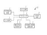
図2は、図1に示された地図情報処理装置a1の詳細を示すブロック図である。図2に示すように、地図情報処理装置a1は、入力装置1、位置検出装置2、送受信装置(受信部)3、地図情報記憶装置4、更新指示情報記憶装置(格納部)5、プロセッサ(更新処理部)6、および出力装置7を備える。
【0010】
入力装置1は、使用者の操作または指示に従ってプロセッサ6に指示信号を与える。具体的には、図示しないが、入力装置1は使用者の音声を認識して音声に基づく指示信号を出力する音声認識装置、使用者の手動操作により指示信号を出力するボタン、その他の適切な入力装置の少なくともいずれかを有していてよい。位置検出装置2はGPS(Global Positioning System)受信機等であって現在位置を検出し、検出した位置情報をプロセッサ6に供給する。
【0011】
地図情報記憶装置4には地図情報が格納されている。送受信装置3は地図情報を更新するために更新指示情報要求を地図情報提供装置a2に送信する機能と、地図情報提供装置a2から更新指示情報を受信する機能を有する。
【0012】
送受信装置3が受信した更新指示情報をプロセッサ6は更新指示情報記憶装置5に格納する。また、プロセッサ6は、更新指示情報に従って地図情報を変更すなわち更新し、このように更新された地図情報を更新指示情報記憶装置5に格納する。但し、この発明をこの実施の形態に限定する意図ではなく、更新された地図情報を地図情報記憶装置4に格納(すなわち上書き保存)してもよい。
【0013】
さらにプロセッサ6は、位置検出装置2から得られた現在位置と地図情報記憶装置4または更新指示情報記憶装置5から読み出した地図情報を用いて、各種のナビゲーション処理を行う。ナビゲーション処理としては、車両が走行している道路および道路上の位置を同定するマップマッチング、出発値から目的地までの経路を算出する経路計算(経路探索)、その結果得られた好適な経路の候補を道路地図と共に表示装置の画面に表示する経路表示、好適な経路に従って出発値から目的地までの案内を行う経路誘導、および現在位置周辺の地図の表示処理等が含まれる。
【0014】
出力装置7は、プロセッサ6のナビゲーション処理出力に従って、使用者に情報を提示する。具体的には、図示しないが、出力装置7は、地図、現在位置、経路、案内情報等を表示する表示装置、および使用者に音声で指示または案内を行う音声発生装置を有していてよい。
【0015】
図3は、図1に示された地図情報提供装置a2の構成を示すブロック図である。地図情報提供装置a2は、送受信装置(送信部)10、更新指示情報記憶装置(更新指示情報記憶部)11および更新指示情報配信装置12を備える。更新指示情報記憶装置11には、配下の地図情報処理装置a1に地図情報を更新させるための更新指示情報を有する更新指示情報データベースが格納されている。送受信装置10は通信網を介してリンクされた各地図情報処理装置a1の送受信装置3から信号を受信し、各地図情報処理装置a1の送受信装置3に個別に信号を送信する機能を有する。更新指示情報配信装置12は、送受信装置10が地図情報処理装置a1から更新指示情報要求を受信すると、所要の更新指示情報を更新指示情報記憶装置11から取得し(読み出し)、対象となる地図情報処理装置a1に向けてその更新指示情報を送受信装置3で送信させる。
【0016】
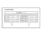
図4は、地図情報処理装置a1の地図情報記憶装置4に格納された地図情報の概略データ構造を示す。地図情報は、管理情報フレーム、複数の表示系データフレーム、複数の経路計算系データフレーム、案内検索データフレーム、およびその他の種類のデータを有している。
【0017】
各表示系データフレームは一つの地域(領域)に対応し、その領域を示す地図およびその領域に関連する関連情報を出力装置7の表示装置に表示させるための各種のデータを有する。各経路計算系データフレームも一つの地域(領域)に対応し、その領域内の道路のノード(交差点または端点)を示すデータを有する。
【0018】
案内検索データフレームは、例えば、目的地のデータ(住所、建物の電話番号等)と、目的地と領域の関連性を示す情報を有しており、使用者が指定した目的地に従って必要な領域の表示系データフレームおよび経路計算系データフレームを選定するために使用される。
【0019】
管理情報フレームは、表示系データフレーム、経路計算系データフレーム、案内検索データフレーム等の管理および読出しのために使用されるデータ、例えば、地図情報における各データフレームの所在、各データフレームの版を示すデータを有する。
【0020】
図4に示すように、各表示系データフレームは、マップマッチング(現在位置に基づいた道路の特定および道路上の位置の同定)や道路の表示に使用する道路データフレーム、河川、海等の地図背景を表示するための背景データフレーム、地名等の名称を文字で表示するための名称データフレーム、経路誘導のための経路誘導データフレーム、周辺施設を検索するための周辺施設データフレーム等を有する。また、各表示系データフレームは表示系データヘッダを有しており、表示系データヘッダは、当該表示系データフレームが対応する領域を表す情報等を含む表示系データフレームに関する各種属性、この表示系データフレームに含まれる各データフレームの所在を管理する情報等を有する。
【0021】
また、経路計算系データフレームは、経路計算のための経路計算データフレームと、経路計算系データヘッダとを有する。経路計算系データヘッダは、当該経路計算系データフレームが対応する領域を表す情報等を含む経路計算系データフレームに関する各種属性、この経路計算系データフレームに含まれる各経路計算データフレームの所在を管理する情報等を有する。
【0022】
この実施の形態による地図情報の更新を説明する前に、地図情報のデータ構造、データ要素の詳細および地図情報の作成の基本原理を説明する。図5は、ある領域に設けられている実際の道路網を示す地図である。図5の例では、ほぼ横方向に延びる二本の道路0,1に複数の道路2〜5が交差している。
【0023】
図6は、表示系データフレームの作成にあたって、図5の道路0〜5の接続関係を示すため、すなわち道路0〜5を道路網としてデータに表現するために仮想的に割り振られるノード、リンクを示す。道路0〜5の交差点および端点には、ノードNd0〜Nd11が割り振られる。また、隣接する二つのノードを結ぶ道路部分には、リンクLd0〜Ld13が割り振られる。以下、図示のような地図表示やマップマッチングに使用する道路網を構成するリンクLd0〜Ld13を表示系リンクと呼ぶ。さらに、各道路の形状を線分の集合として表すために、各道路の屈曲点には、補間点P0〜P24が割り振られる。
【0024】
図6に示すように、表示系データフレームの作成にあたって、1つの道路をリンク列として取り扱う。すなわち、道路0(図5)はリンク列0と呼ばれ、同様に道路1〜5はリンク列1から5と呼ばれる。道路0を表現するリンク列0は、ノードNd0,Nd1,Nd2,Nd3,Nd4,Nd5、リンクLd0,Ld1,Ld2,Ld3,Ld4を有する。また、表示系データフレームの作成にあたって、各道路すなわちリンク列には方向性を与えておく、例えば、リンク列0については、ノードNd0からNd5へ向かう方向を順方向とし、ノードNd5からNd0へ向かう方向を逆方向とする。
【0025】
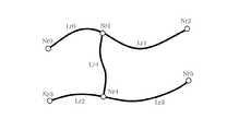
図7は、経路計算系データフレームの作成にあたって、経路計算に使用する重要な道路0,1,3からなる道路網に仮想的に割り振られるノード、リンクを示す。ここでは、他の道路2,4,5は経路計算には使用しないと想定する。道路0,1,3の交差点および端点には、ノードNr0〜Nr5が割り振られる。また、隣接する二つのノードを結ぶ道路部分には、リンクLr0〜Lr4が割り振られる。以下、図示のような経路計算に使用する道路網を構成するリンクLr0〜Lr4を経路計算系リンクと呼ぶ。
【0026】
図8は、図6の道路網を構成する道路0〜5を表すリンク列0〜5、および各表示系リンクLd0〜Ld13に識別のために付与されたリンク識別番号を示す。例えば、リンクLd0のリンク識別番号は100、リンクLd10のリンク識別番号は110である。リンク識別番号は同一リンク列内では、リンク列の順方向に昇順でかつ連番となるように各リンクに付与される。
【0027】
図8に示すように、道路の交差は、リンク列の交差すなわち接続として表すことができる。例えば、道路0と道路2の交差点は、リンク列0のノードNd1、リンク列2のノードNd1’に対応している。つまり、リンク列0,2は、ノードNd1およびノードNd1’で接続されているとみなすことができる。このことを利用して、各ノードについて、他のリンク列との接続を表す交差情報を表現できる。例えば、リンク列0のノードNd1の交差情報は接続先としてリンク列2のノードNd1’を示し、リンク列2のノードNd1’の交差情報は接続先としてリンク列0のノードNd1を示すようにである。このように各ノードに交差情報を付与することによって、交差するリンク列、ひいては全体のリンク列の接続関係を把握することができる。
【0028】
図9は、図7の経路計算系リンクLr0〜Lr4と、図8に示されたリンク識別番号との関係を示す。図7の経路計算系リンクLr0〜Lr4のそれぞれには、先頭リンク識別番号と終端リンク識別番号が付与される。すなわち図7の1つのリンク(例えばリンクLr1)には、これに対応する図8のリンク(例えばリンクLd2からLd4)に付与された最小のリンク識別番号(例えば102)が先頭リンク識別番号として付与され、最大のリンク識別番号(例えば104)が終端リンク識別番号として付与される。各リンク識別番号はリンク列の順方向に昇順でかつ連番に付与されるため、図7の経路計算系リンクに対応する図8の表示系リンクは、その先頭リンク識別番号および終端リンク識別番号により特定できる。例えば、図7のリンクLr1については、リンク識別番号102〜104であるリンクLd2,Ld3,Ld4が特定される。
【0029】
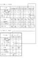
図10(a)は、図4の表示系データフレームにおける道路データフレームの例を示す。道路データフレームは、道路データヘッダと複数のリンク列レコードを有する。図10(a)の道路データフレームは図8の道路網を表す。図中のリンク列レコードMR0〜MR5は、図8のリンク列0〜5にそれぞれ対応するように設けられており、対応するリンク列(道路)に関する情報が格納される。リンク列レコードの並び順をリンク列番号と呼び、リンク列番号0〜5を用いてリンク列レコードMR0〜MR5を特定できる。道路データヘッダにはリンク列レコードの数等のリンク列レコードを管理するための情報が格納される。
【0030】
図10(a)のリンク列レコードMR0〜MR5について、リンク列レコードMR0(リンク列0に対応する)を例に説明する。図10(b)は図10(a)のリンク列レコードMR0のデータ構造を示す。リンク列レコードは、リンク列ヘッダと複数のノードリンクレコードを有する。図10(b)のノードリンクレコードNLR00,NLR01,NLR02,NLR03,NLR04,NLR05は、リンク列0を順方向にたどったときに出現するノードとリンクの対(Nd0,Ld0)、(Nd1,Ld1)、(Nd2,Ld2)、(Nd3,Ld3)、(Nd4,Ld4)、(Nd5,なし)にそれぞれ対応する。リンク列レコードMR0において、ノードリンクレコードNLR00〜NLR05は、対応するノードとリンクの対の出現順に従って配置され、ノードリンクレコードNLR00〜NLR05の並び順をノードリンク番号と呼ぶ。ノードリンク番号0〜5を用いてノードリンクレコードNLR00〜NLR05を特定できる。
【0031】
ノードリンクレコードには、対応するノード及びリンクに関する情報が格納される。例えば、ノードリンクレコードNLR00には、ノードNd0及びリンクLd0(リンク識別番号100)に関する情報が格納される。リンク列ヘッダには、当該リンク列レコードのデータサイズ、当該道路(例えばリンク列レコードMR0では道路0)の道路種別、当該道路に存在するノード数等が格納される。
【0032】
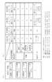
図11は、図10(a)におけるリンク列レコードMR0(リンク列0に対応)のノードリンクレコードNLR00〜NLR05、およびリンク列レコードMR5(リンク列5に対応)のノードリンクレコードNLR50,NLR51を示す。各ノードリンクレコードは、ノードリンクヘッダ、交差情報、ノード座標、リンク識別情報、副リンク識別情報、補間点情報を有する。
【0033】
ノードリンクヘッダには、対応するリンクの補間点の数、および対応するリンクに副リンク識別番号が付与されているか否かを示す副リンク識別有無情報が格納される。また、図示していないが、当該ノードリンクレコードのデータサイズ、対応するリンクの道路幅員等のリンク属性等も格納される。副リンク識別番号は、道路の新設等の道路網の変更または現実の道路に即した地図情報の充足のための更新後の道路データフレームで使われるのであって、これについてはデータの更新に関連して後にさらに詳細に説明する。図11の例では、変更前の図8の道路網に副リンク識別番号は付与されていないので、副リンク識別有無情報は「なし」を示す値が格納されている。
【0034】
交差情報には、接続先のリンク列を示すリンク列番号、接続先のリンク列のノードに対応するノードリンクレコードのノードリンク番号が格納される。例えば、リンク列レコードMR0のノードリンクレコードNLR04(図8のノードNd4およびリンクLd4に対応する)の交差情報は、リンク列番号5およびノードリンク番号0によって、ノードNd4が接続されたリンク列5のノードNd4’を示す。また、リンク列レコードMR5のノードリンクレコードNLR50(図8のノードNd4’およびリンクLd13に対応する)の交差情報は、リンク列番号0およびノードリンク番号4によって、ノードNd4’が接続されたリンク列0のノードNd4を示す。このようにノードリンクレコードNLR04,NLR50の交差情報は、リンク列0のノードNd1とリンク列5のノードNd4’が接続していることを示している。道路の端点に係るノードNd0,Nd5に対応するノードリンクレコードNLR00,NLR05では、接続先のリンクがないので、リンク列番号およびノードリンク番号に−1が格納される。
【0035】
ノード座標には、対応するノードの地理的位置を示す座標値が格納される。リンク識別情報には対応するリンクに付与されたリンク識別番号が格納される。例えば、ノードリンクレコードNLR00では、対応するノードNd00の座標と対応するリンクLd0のリンク識別番号100がそれぞれノード座標、リンク識別情報に格納される。尚、末尾のノードリンクレコード(例えばNLR05,NLR51)のリンク識別情報には、対応するリンクが存在しないため−1を格納する。
【0036】
副リンク識別情報は、道路の新設等の道路網の変更または現実の道路に即した地図情報の充足のための更新後の道路データフレームで使われるのであって、対応するリンクに副リンク識別番号が付与されているときのみ存在し、副リンク識別情報には対応するリンクの副リンク識別番号が格納される。図11の例では、図8の変更前の道路網に副リンク識別番号は付与されていないので、副リンク識別有無情報は設けない。
補間点情報は対応するリンクが一つ以上の補間点を有するときのみに存在し、補間点情報にはリンクの各補間点の地理的位置を示す座標値が格納される。例えば、リンク列レコードMR0のノードリンクレコードNLR04(図8のノードNd4およびリンクLd4に対応する)では、リンクLd4上の補間点P4の座標が補間点情報に格納される。
【0037】
図12は、同様に図10(a)におけるリンク列レコードMR1(リンク列1に対応)のノードリンクレコードNLR10〜NLR15、およびリンク列レコードMR3(リンク列3に対応)のノードリンクレコードNLR30,NLR31のデータ構造および格納内容を示す。マップマッチングや道路の表示等に使用される表示系データフレームは、以上の構造を有する。
【0038】
図13は図4の経路計算系データフレームにおける経路計算データフレームの例を示す。経路計算データフレームは、経路計算データヘッダとノードレコードを有する。図13の経路計算データフレームは、図7の道路網を表すと想定する。図中のノードレコードNrR0〜NrR5は、図7のノードNr0〜Nr5にそれぞれ対応するように設けられている。経路計算データヘッダには、ノードレコード数等のノードレコードを管理するための情報が格納されている。ノードレコードには、対応するノードに関する情報が格納される。ノードレコードの並び順をノード番号と呼ぶ。
【0039】
図13のノードレコードについて、ノードレコードNrR1(ノードNr1に対応する)を例に説明する。図14は図13のノードレコードNrR1のデータ構造を示す。ノードレコードは、ノードレコードヘッダと、一つ以上の接続レコードを有する。図14の接続レコードCR10,CR11,CR12は、当該ノードレコードNrR1に対応するノードNr1に接続されるリンクLr1,Lr4,Lr0にそれぞれ対応する。
【0040】
ノードレコードヘッダには、当該ノードレコードのデータサイズ、当該ノードレコードに対応するノードNr1の地理的位置を示す座標値、当該ノードレコードの接続レコードの数等が格納される。
【0041】
各接続レコードは、接続レコードヘッダ、隣接ノード番号、リンクコスト、対応リンク識別情報、対応副リンク識別情報、および通行規制情報を有する。
接続レコードヘッダには、当該接続レコードのデータサイズ、対応副リンク識別情報の有無を示す対応副リンク識別有無情報が格納される。対応副リンク識別情報は、道路の新設等の道路網の変更または現実の道路に即した地図情報の充足のための更新後の経路計算データフレームで使われるのであって、これについてはデータの更新に関連して後にさらに詳細に説明する。図14の例では、図8の変更前の道路網に副リンク識別番号は付与されていないので、副リンク識別有無情報は「なし」を示す値が格納されている。
【0042】
隣接ノード番号には、当該ノード(ノードNr1)に接続されるリンク(リンクLr1,Lr4,Lr0のいずれか)上の当該ノードに隣接するノード(ノードNr2,Nr4,Nr0のいずれか)のノード番号が格納される。例えば、接続レコードCR10では、リンクLr1によりノードNr1と隣接するノードNr2のノード番号2が隣接ノード番号として格納される。
【0043】
リンクコストには、経路計算でのコスト評価のための指標として、当該接続レコードに対応するリンク(例えば、接続レコードCR10ではリンクLr1)の走行に要する所要時間等が格納される。
【0044】
対応リンク識別情報は、当該接続レコードに対応するリンクの先頭リンク識別番号および終端リンク識別番号(図8参照)を格納する。
【0045】
対応リンク副識別情報には、道路の新設等の道路網の変更または現実の道路に即した地図情報の充足のための更新後の経路計算データフレームで使われるのであって、当該接続レコードに対応するリンクの先頭副リンク識別番号および終端副リンク識別番号を格納する。但し、図14の例では、図8の変更前のリンクには副リンク識別番号が付与されていないため、対応リンク副識別情報は設けない。対応リンク識別情報(対応副リンク識別情報がある場合には対応リンク識別情報と対応副リンク識別情報)によって、当該接続レコードに対応する表示系リンクLd0,...(図8)の範囲が示される。
通行規制情報は、当該接続レコードに対応するリンクに関わる通行規制を示す情報を格納する。
経路計算に使用される経路計算系データフレームは、以上の構造を有する。以上説明したデータ構造を有する地図情報が各地図情報処理装置a1の地図情報記憶装置4に格納されている。
【0046】
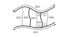
次に、道路の変更または現実の道路に即した地図情報の充足のための地図情報の更新を説明する。図15は、図5に示された道路網に一つの道路6が新設された道路網を示す地図である。図15については、今まで地図情報で無視されてきた道路6についても地図情報で記述することにしたと考えてもよい。新設された道路6は、道路0と道路1に交差する。具体的には、図5の道路0の道路部分r0が道路6によって二つの道路部分r00,r01に分割され、道路1の道路部分r1が道路6によって二つの道路部分r10,r11に分割される。
【0047】
図16は、図8と同様の図であって、表示系データフレームの更新にあたって、図15の変更された道路0〜6の接続関係を示すために仮想的に割り振られるノード、リンク、リンク列、リンク識別番号を示す。図16に示すように、新設された道路6に対応するリンク列6が設けられており、リンク列6は単一のリンクLd14を有する。図8のリンクLd3は、図15の道路部分r00,r01に対応するリンクLd3’,Ld3”に分割され、リンクLd8は、図15の道路部分r10,r11に対応するリンクLd8’,Ld8”に分割されている。換言すれば、リンクLd3はリンクLd3’,Ld3”に置換され、リンクLd8はリンクLd8’,Ld8”に置換されている。道路6(リンク列6)は、道路0(リンク列0)に交差点としてのノードNd12,Nd12’で接続されており、道路1(リンク列1)に交差点としてのノードNd13,Nd13’で接続されている。ノードNd12’,Nd13’、リンクLd14はリンク列6をなす。
【0048】
上記のようにあるリンクを代わりのリンクで置換するとき、リンクLd3,Ld8のように元になったリンクを元リンク、リンクLd3’,Ld3”,Ld8’,Ld8”のような代わりのリンクを代替リンクと呼ぶ。また、元リンクのリンク識別番号(例えば、図8のリンク識別番号103,108)を元リンク識別番号と呼ぶ。
【0049】
また、代替リンクに対して、元リンク識別番号とは別のリンク識別番号である副リンク識別番号を付与し、元リンク識別番号と副リンク識別番号を用いて代替リンクを識別する。副リンク識別番号として、所定範囲内の番号0〜SIDMAXをとれるものとする。例えば、ある元リンクLの代わりに設けられたM本の代替リンクL0,L1,・・・,LM−1が、元リンクLのリンク列の順方向の向きにL0,L1,・・・,LM−1の順に配置されているとき、リンクL0,L1,・・・,LM−1には、それぞれ数値範囲0〜SID1−1,SID1〜SID2−1,・・・,SIDM−1〜SIDMAXを付与する。ここで、0<SID1<SID2<・・・<SIDM−1≦SIDMAXとする。
【0050】
副リンク識別番号がどの元リンクに関するものかを示すために、副リンク識別番号は、元リンクのリンク識別番号と組み合わせられる。すなわち、元リンクのリンク識別番号をidxとし、上記副リンク識別番号sidとするとき、代替リンクには総合リンク識別番号idx:sidが付与される。例えば、元リンクLのリンク識別番号をidxとするとき、代替リンクL0,L1,・・・、LM−1には、総合リンク識別番号idx:0〜idx:SID1−1,idx:SID1〜idx:SID2−1,・・・,idx:SIDM−1〜idx:SIDMAXが付与される。
【0051】
本実施の形態では、SIDMAX=255とし、例えばリンク識別番号103を持つ元リンクLd3の代替リンクLd3’,Ld3”には、副リンク識別番号0〜127,128〜255を与え、その結果、図16に示すように、代替リンクLd3’,Ld3”には、総合リンク識別番号103:0〜103:127、103:128〜103:255を付与する。
【0052】
また、リンク識別番号と総合リンク識別番号の間の便宜上つまりデータ表記上の大小関係を次のように定める。例えば、三つのリンク識別番号id1,id2,id3があって、リンク識別番号id2,id3に関連する二つの総合リンク識別番号をid2:sid2,id3:sid3がある状態を想定する。リンク識別番号と総合リンク識別番号の間のデータ表記上の大小関係は以下のように定められる。
id1>id2 ならば id1>id2:sid2、
id1=id2 ならば id1=id2:sid2、
id1<id2 ならば id1<id2:sid2。
【0053】
総合リンク識別番号同士の間のデータ表記上の大小関係は、以下のように定められる。
id2>id3 ならば id2:sid2>id3:sid3、
id2=id3 のときは、
sid2>id3 ならば id2:sid2>id3:sid3、
sid2=id3 ならば id2:sid2=id3:sid3。
【0054】
また、リンク識別番号同士の間のデータ表記上の大小関係は、リンク識別番号のデータ表記上の大小関係に従うものとする。
【0055】
後述するように、上記データ表記上の大小関係に従って、直列に連なった複数の表示系リンクが占めるリンク識別番号の範囲を表すことができる。このリンク識別番号の範囲は、経路計算系データフレームの更新に使用される。
【0056】
図17は、図7と同様の図であって、経路計算系データフレームの更新にあたって、変更された経路計算に使用する道路0,1,3,6からなる道路網に仮想的に割り振られるノード、リンクを示す。ここでは、追加された道路6は経路計算に使用すると想定する。図17に示すように、新設された道路6に対応するリンクLr5が設けられる。図7のリンクLr1は、リンクLr1’,Lr2”に分割され、リンクLr3は、リンクLr3’,Lr3”に分割されている。換言すれば、リンクLr1はリンクLr1’,Lr1”に置換され、リンクLr3はリンクLr3’,Lr3”に置換されている。また、道路6の新設に伴い、ノードNr6,Nr7が新設されている。
【0057】
経路計算系リンクLr1’は図16の表示系リンクLd2,Ld3’に対応し、リンクLr1”は図16のリンクLd3”,Ld4に対応し、リンクLr3’は図16のリンクLd7,Ld8’に対応し、リンクLr3”は図16のリンクLd8”,Ld9に対応し、リンクLr5は図16のリンクLd14に対応する。
【0058】
図16の表示系リンクLd2,Ld3’、すなわち経路計算系リンクLr1’が占めるリンク識別番号の範囲は、元リンク識別番号102および総合リンク識別番号103:0〜103:127に基づいて、上記の表記上の大小関係に従って、102〜103:127と決定され、これは102/103:127と表記される。また、図16の表示系リンクLd3”,Ld4、すなわち経路計算系リンクLr1”が占めるリンク識別番号の範囲は、総合リンク識別番号103:128〜103:255および元リンク識別番号104に基づいて、上記の表記上の大小関係に従って、103:128〜104と決定され、103:128/104と表記される。図17のリンク識別番号の範囲は、図9の先頭リンク識別番号/終端リンク識別番号の対に対応する。
【0059】
リンク識別番号の範囲102〜103:127には、元リンク識別番号102,103、総合リンク識別番号102:0〜102:255、103:0〜103:127が含まれる。また、リンク識別番号の範囲103:128〜104には、元リンク識別番号103,104、総合リンク識別番号103:128〜103:255、104:0〜104:255が含まれる。
【0060】
上記のように代替リンクのリンク識別番号として、元リンク識別番号と副リンク識別番号を用いることにより、版の異なる地図情報のデータフレーム(例えば旧版の表示系データフレームと新版の経路計算系データフレーム)における表示系リンクと経路計算系リンクの対応付けが可能となる。
【0061】
同様の手法で、図17に示すように、経路計算系リンクLr3’,Lr3”にも、元リンク識別番号と総合リンク識別番号に基づいて、リンク識別番号の範囲が付与される。変更のない経路計算系リンクLr0,Lr2,Lr4については、先頭リンク識別番号/終端リンク識別番号の対は変更しない。新設されたLr5については、先頭リンク識別番号および終端リンク識別番号はともに114である。
【0062】
図18に示す道路データフレームは図16の道路網を表す更新された道路データフレームである。図18に示す道路データフレーム中、リンク列レコードMR0’,MR1’,MR5’は道路0,1,5にそれぞれ対応しており、図10の道路データフレーム中、リンク列レコードMR0,MR1,MR5の一部を更新したものである。また、新たなリンク列6を表すリンク列レコードMR6が追加されている。また、道路データヘッダもこれらのリンク列レコードの更新に従い更新されている。
【0063】
図19は、図18におけるリンク列レコードMR0’(リンク列0に対応)のノードリンクレコードNLR00〜NLR05、およびリンク列レコードMR5’(リンク列5に対応)におけるノードリンクレコードNLR50,NLR51を示す。図19中のリンク列レコードの各ノードリンクレコードの構造は、図11に示す元のリンク列レコードの各ノードリンクレコードの構造と同じである。図19中の新リンク列レコードMR0’は、図11中の元のリンク列レコードMR0に対し、新ノードリンクレコードNLR04Iが挿入され、旧ノードリンクレコードNLR03を改変した新ノードリンクレコードNLR03’を有する点で異なる。
【0064】
新たに追加されたノードリンクレコードNLR04Iは、図16に示される新設されたノードNd12とその順方向に存在するリンクLd3”に対応する。また、旧ノードリンクレコードNLR03は、図8に示されるノードNd3とリンクLd3に対応するのに対して、改変した新ノードリンクレコードNLR03’は、図16に示されるノードNd3とリンクLd3’に対応する。元リンクLd3が新リンクLd3’,Ld3”に分割されたことに伴い、新ノードリンクレコードNLR03’では、副リンク識別有無情報が「あり」を示すように変更され、補間点数および補間点座標が更新され、副リンク識別情報が挿入されている。また、追加されたノードリンクレコードNLR04Iでも、副リンク識別有無情報が「あり」を示しており、副リンク識別情報が有効である。
【0065】
ノードリンクレコードNLR03’,NLR04Iの副リンク識別情報には、リンクLd3’,Ld3”に付与された副リンク識別番号の最小値(図16に示すようにリンクLd3’では0、リンクLd3”では128)を格納する。各リンクに付与されている副リンク識別番号の範囲は、そのノードリンクレコードと次のノードリンクレコードのリンク識別番号、副リンク識別番号から判定することができる。例えばノードリンクレコードNLR03’,NLR04Iのリンク識別情報が同じで(リンク識別番号=103)、ノードリンク番号が4(図10(b)参照)であるノードリンクレコードNLR04Iの副リンク識別情報が128であるから、ノードリンク番号が3であるリンクLd3’には0〜127(=128−1)の副リンク識別番号の範囲が付与されていると判定できる。ノードリンク番号が4,5のノードリンクレコードNLR04I,NLR04のリンク識別情報が異なっているため、リンクLd3”には128〜255の副リンク識別番号が付与されていると判定できる。
【0066】
他方、リンク列レコードMR5’(リンク列5に対応)は、図11中の元のリンク列レコードMR5中の、ノードリンクレコードNLR50,NLR51の交差情報のノードリンク番号を変更したものである。これは、リンク列0へのノードNd12の追加(図16参照)により、既存のノードNd4(ノードリンクレコードNLR50に対応)のノードリンク番号が4から5に変化し、リンク列1へのノードNd13の追加により、既存のノードNd10(ノードリンクレコードNLR51に対応)のノードリンク番号も4から5に変化するためである。
【0067】
図20は、図18におけるリンク列レコードMR1’(リンク列1に対応)のノードリンクレコードを示す。リンク列レコードMR1’は、リンク列レコードMR0’と類似の形式で更新されている。すなわち、図20の新リンク列レコードMR1’は、図12中の元のリンク列レコードMR1に対し、新ノードリンクレコードNLR14Iが挿入され、旧ノードリンクレコードNLR13を改変した新ノードリンクレコードNLR13’を有する点で異なる。
尚、これらのリンク列レコードMR0’,MR1’,MR5’の内容の更新に伴い、各リンク列レコードのリンク列ヘッダ(図10(b)参照)も更新される。
【0068】
図21は、図17に示す変更後の道路網を表す経路計算データフレームを示し、図22は、図21の一つのノードレコードのデータ構造を示す。図21および図22の経路計算データフレームおよびノードレコードの構造は、図13および図14に示す元の経路計算データフレームおよびノードレコードの構造と同じである。図21中の経路計算データフレームは、図13中の元の経路計算データフレームに対し、新ノードレコードNrR6,NrR7が追加され、旧ノードレコードNrR1,NrR2,NrR4,NrR5を改変した新ノードレコードNrR1’,NrR2’,NrR4’,NrR5’を有する点で異なる。
【0069】
新たに追加されたノードレコードNrR6,NrR7は、図17に示される新設されたノードNr6,Nr7にそれぞれ対応する。また、更新されたノードレコードNrR1’,NrR2’,NrR4’,NrR5’は、旧ノードレコードNrR1’,NrR2’,NrR4’,NrR5’と同様に、ノードNr1,Nr2,Nr4,Nr5にそれぞれ対応する。また、ノードレコードの更新に従い、経路計算データヘッダも更新されている。
【0070】
図21のノードレコードについて、ノードレコードNrR1’(ノードNr1に対応する)を例に説明する。図22は図21のノードレコードNrR1’のデータ構造を示す。図22のノードレコードNrR1’は、図14のノードレコードNrR1のノードレコードヘッダ、接続レコードCR10を以下のように更新したものである。
【0071】
まず、道路6の追加により、図17においてノードNr1に元リンクLr1に代わる代替リンクLr1’が接続され、ノードNr1の隣接ノードはノードNr2に代わりノードNr6となるため、接続レコードCR10の接続レコードヘッダの対応副リンク識別有無情報(終端)を「あり」とし、隣接ノード番号を値2からノードNr6を示す値6に置換し、リンクコストをリンクLr1’に応じた値に置換し、対応リンク識別情報の終端リンク識別番号を103に置換する。対応副リンク識別有無情報の終端が「あり」ということは、元のリンク(例えばLr1)がその順方向に進む途中で分割されたこと、つまり代替リンク(例えばLr1’)の終端が副リンク識別番号を持つことを示す。逆に、対応副リンク識別有無情報の先頭が「あり」ということは、元のリンク(例えばLr1)がその逆方向に進む途中で分割されたこと、つまり代替リンクの先頭が副リンク識別番号を持つことを示す。
【0072】
また、先頭副リンク識別番号を0、終端副リンク識別番号を127とした対応副リンク識別情報を挿入する。先頭副リンク識別番号には、当該代替リンクに付与された副リンク識別番号の範囲の最小値が与えられ、終端副リンク識別番号にはその副リンク識別番号の範囲の最大値が与えられる。これらの対応リンク識別情報および対応副リンク識別情報は協働して、リンクLr1’が図16に示されたリンク識別番号の範囲が102〜103:127にある直列したリンク、すなわちリンクLd2,Ld3’に対応していることを示している。従って、新版の経路計算データフレームに基づいて旧版の道路データフレーム中の対応リンクが判定できる。
【0073】
図23は、図21の経路計算データフレーム中の追加されたノードレコードの例として、ノードレコードNrR6を構成する接続レコードの主な内容を示す。図23の接続レコードCR60,CR61,CR62は、当該ノードレコードNrR6に対応するノードNr6に接続されるリンクLr1”,Lr5,Lr1’にそれぞれ対応する。接続レコードCR60は、隣接ノード番号により、リンクLr1”を介したノードNr6の隣接ノードがノードNr2(図17参照)であることを示し、対応リンク識別情報および対応副リンク識別情報により、リンクLr1”が図16に示されたリンク識別番号の範囲が103:128〜104にある直列したリンクすなわちリンクLd3”,Ld4に対応していることを示す。接続レコードCR61は、隣接ノード番号により、リンクLr5を介したノードNr6の隣接ノードがノードNr7であることを示し、対応副リンク識別有無情報および対応リンク識別情報により、リンクLr5が図16に示されたリンク識別番号の範囲が114のリンクすなわちリンクLd14に対応していることを示す。接続レコードCR62は、隣接ノード番号により、リンクLr1’を介したノードNr6の隣接ノードがノードNr1であることを示し、対応リンク識別情報および対応副リンク識別情報により、リンクLr1’が図16に示されたリンク識別番号の範囲が102〜103:127の直列したリンクすなわちリンクLd2,Ld3’に対応していることを示す。
【0074】
以上、更新された地図情報は、図15から図23を参照しながら説明した基本原理に従ったデータ構造を有する。上記のように代替リンクのリンク識別番号として、元リンク識別番号と副リンク識別番号を用いることにより、版の異なる地図情報のデータフレーム(例えば旧版の表示系データフレームと新版の経路計算系データフレーム)における表示系リンクと経路計算系リンクの対応付けが可能となる。
【0075】
従って、更新された地図情報を地図情報処理装置a1が取得できれば、その地図情報処理装置a1でも最新の実際の道路についての地図表示、マップマッチングおよび経路計算が可能である。上述の通り、仮に表示系データフレームと経路計算系データフレームの版が異なっていても、リンクの対応付けが可能であることから、地図情報処理装置a1では、片方のデータフレームしか取得できなくても正しく経路を表示することが可能である。更新された地図情報を地図情報処理装置a1が取得するための方法として、この実施の形態では、地図情報提供装置a2が地図情報処理装置a1に更新指示情報を送信し、更新指示情報に従って地図情報処理装置a1が元の地図情報を変更すると、更新された地図情報を得ることができる(つまり個々の地図情報処理装置a1でも地図情報を更新できる)。
【0076】
次に、地図情報処理装置a1が地図情報を更新する方法を説明する。図24は地図情報提供装置a2の更新指示情報記憶装置11(図3参照)に格納された更新指示情報データベースの構造を示す。地図情報提供業者は更新指示情報(後述する)を更新指示情報データベースに追加するときに、追加に伴い必要な改変を更新指示情報データベースの他の要素(後述する版数管理情報)に行う。
【0077】
更新指示情報データベースは、一つの版数管理情報と、一つ以上の版別情報の並びを有する。各版別情報はある版の地図情報を最新版の地図情報に更新するための情報であって、既存の版の数だけ存在する。版数管理情報は、これらの版別情報を管理する情報であって、各版別情報の版数、所在、データサイズ等を示す。
【0078】
各版別情報は、一つの更新指示情報管理情報と、一つ以上の更新指示情報の並びを有する。更新指示情報は、該当する版の表示系データフレームおよび経路計算系データフレームについて設けられており、各版の表示系データフレームおよび各版の経路計算系データフレームを最新版に更新するために設けられている。但し、管理情報フレーム、案内検索データフレーム(図4参照)、またはその他のデータフレームについても、更新指示情報を設けてもよい。更新指示情報管理情報は、これらの更新指示情報を管理する情報であり、各更新指示情報の所在、データサイズ等を示す。
【0079】
地図情報提供装置a2は、更新指示情報要求を地図情報処理装置a1から受信すると、更新指示情報記憶装置11内の更新指示情報データベース中の版数管理情報および更新指示情報管理情報を参照し、所要の更新指示情報を取得して、これを地図情報処理装置a1に送信する。
【0080】
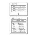
図25は、図24に示された更新指示情報のデータ構造の例を示す。図25に示すように、更新指示情報は、一つの更新指示情報ヘッダと、一つ以上の更新操作レコードの並びを有する。更新指示情報ヘッダは、更新対象のデータフレームの種類区分と領域(該当地域)を示す。すなわち、更新指示情報ヘッダは、管理情報フレーム、表示系データフレーム、経路計算系データフレーム等の更新すべきデータフレームの種類区分(図4参照)を指定する更新データ区分指定と、更新するデータフレームの該当領域を示す領域指定(地域指定)を有する。
【0081】
更新操作レコードは、更新指示情報ヘッダで示されたデータフレームに対して更新のために施すべきデータ操作を示す。各更新操作レコードは、更新対象種別と、更新操作指定と、更新対象位置と、更新データを有する。更新対象種別は、更新指示情報ヘッダが示すデータフレーム内における更新対象とするデータの種別として表示系データヘッダ、道路データフレーム、経路計算系データヘッダ、または経路計算データフレーム等を指定する。更新操作指定は、削除、追加、挿入、上書き等の更新操作の種類を指定する。
更新対象位置は、更新対象種別で指定されたデータ内における更新対象の位置を示す。更新データは、追加、挿入、または上書きされるデータの内容そのものである。削除の場合には、更新データは設けない。
【0082】
更新対象位置は、より具体的には、第1レコード番号、第2レコード番号、更新対象オフセットおよび更新対象データサイズを有する。第1レコード番号は、更新の対象となるリンク列レコードのリンク列番号(図10(a)および図18参照)、または更新の対象となるノードレコードのノード番号(図13および図21参照)等を示す。第2レコード番号は、第1レコード番号で指定されたレコード内における、ノードリンクレコードのノードリンク番号(図10(b)参照)、接続レコードのレコード番号(図14および図22参照)を示す。更新対象オフセットは、第2レコード番号で指定されたレコード(ノードリンクレコード、接続レコード等)内の更新箇所の先頭を第2レコード番号で指定されたレコード先頭からのバイト数で示す。更新対象データサイズは、削除または更新するデータのデータサイズを示す。
【0083】
但し、ヘッダ(道路データヘッダ、リンク列ヘッダ、経路計算データヘッダ、ノードレコードヘッダ等)には、リンク列番号、ノードリンク番号、ノード番号等の番号が与えられていないので、道路データヘッダ、経路計算データヘッダ等を示す第1レコード番号には−1を与え、リンク列ヘッダ、ノードレコードヘッダを示す第2レコード番号にも−1を与える。また、更新すべきヘッダまたは各レコードのうち特定箇所を更新するのではなく、ヘッダまたはレコード全体を一括して更新する場合には、更新対象オフセットの指定が不要であるので、更新対象オフセットに−1を与える。
第1レコード番号、第2レコード番号、および更新対象オフセットには、更新前の版で使用されている値を使用する。
【0084】
図26(a)および図26(b)を参照しながら、図10(a)の道路データフレームを図18の道路データフレームに更新するための更新指示情報を説明する。図26(a)は、道路データフレームの更新のための更新操作レコードを含む更新指示情報を示す。図示の更新指示情報ヘッダでは、詳細な図示はしないが更新データ区分指定を表示系データフレームを表す1とし、領域指定(地域指定)を表示系データフレームの該当領域とする。図中の更新操作レコード群OPD1は、表示系データフレーム中の道路データヘッダを更新するための更新操作レコードの集合である。更新操作レコード群OPD2は、図10(a)のリンク列レコードMR0,MR1,MR5を図18のリンク列レコードMR0’,MR1’,MR5’に更新するための更新操作レコードの集合である。更新操作レコード群OPD3は、図18のリンク列レコードMR6を追加するための更新操作レコードの集合である。
【0085】
図26(b)は、図10(a)のリンク列レコードMR0を図18のリンク列レコードMR0’に更新するための更新操作レコード0,1,2,3を示す。つまり、図示の更新操作レコード0〜3は、図26(a)の更新操作レコード群OPD2の一部である。図26(b)中の更新対象位置について、第1レコード番号0はリンク列番号0、つまり旧リンク列レコードMR0を示し、第2レコード番号−1,3,4はノードリンク番号「なし」,3,4、つまり旧リンク列ヘッダと旧ノードリンクレコードNLR03,NLR04を示す。さらに、更新指示情報オフセット−1は、ヘッダまたはレコード全体を一括して更新することを示す。
【0086】
従って、更新操作レコード0は、図10(a)のリンク列レコードMR0内のリンク列ヘッダを図18のリンク列レコードMR0’内のリンク列ヘッダで上書きする操作を指定する。更新操作レコード1は、図11のリンク列レコードMR0内のノードリンク番号3のノードリンクレコードNLR03を削除する操作を指定する。更新操作レコード2は、図11のリンク列レコードMR0内のノードリンク番号4のノードリンクレコードNLR04の前に、図19のリンク列レコードMR0’のノードリンク番号3のノードリンクレコードNLR03’を挿入する操作を指定する。更新操作レコード3は、図11のリンク列レコードMR0のノードリンク番号4のノードリンクレコードNLR04の前に、図19のリンク列レコードMR0’のノードリンク番号4のノードリンクレコードNLR04Iを挿入する操作を指定する。
【0087】
更新操作レコード2,3によって挿入されるノードリンクレコードNLR03’,NLR04Iには、代替リンクLd3’のリンク識別情報および副リンク識別情報として、元リンクLd3のリンク識別番号103と代替リンクLd3’の副リンク識別番号0〜127を示す情報が含まれており(図19参照)、代替リンクLd3”のリンク識別情報および副リンク識別情報として、元リンクLd3のリンク識別番号103と代替リンクLd3”の副リンク識別番号128〜255を示す情報が含まれている(図19参照)。
【0088】
従って、図26(a)および図26(b)に示される更新指示情報を受信すると、地図情報処理装置a1では、かかる更新操作レコードの指示に従った更新操作を行うことにより、更新指示情報ヘッダで指定されたデータフレームつまり表示系データフレームを更新することができる。
【0089】
次に、図27(a)および図27(b)を参照しながら、図13の経路計算データフレームを図21の経路計算データフレームに更新するための更新指示情報を説明する。図27(a)は、経路計算データフレームの更新のための更新操作レコードを含む更新指示情報を示す。図示の更新指示情報ヘッダでは、詳細な図示はしないが更新データ区分指定を経路計算系データフレームを表す2とし、領域指定(地域指定)を経路計算系データフレームの該当領域とする。図中の更新操作レコード群OPR1は、経路計算系データフレーム中の経路計算データヘッダを更新するための更新操作レコードの集合である。更新操作レコード群OPR2は、図13のノードレコードNrR1,NrR2,NrR4,NrR5を図21のノードレコードNrR1’,NrR2’,NrR4’,NrR5’に更新するための更新操作レコードの集合である。更新操作レコード群OPR3は、図21のノードレコードNrR6,NrR7を追加するための更新操作レコードの集合である。
【0090】
図27(b)は、図14のノードレコードNrR1を図22のノードレコードNrR1’に更新するための更新操作レコード0,1,2を示す。つまり、図示の更新操作レコード0〜2は、図27(a)の更新操作レコード群OPR2の一部である。図27(b)中の更新対象位置について、第1レコード番号1はノード番号1、つまり旧ノードレコードNrR1を示し、第2レコード番号−1,0,1は接続レコード番号なし,0,1、つまり旧ノードレコードヘッダと旧接続レコードCR10,CR11を示す。さらに、更新指示情報オフセット−1は、ヘッダまたはレコード全体を一括して更新することを示す。
【0091】
従って、更新操作レコード0は、図14のノードレコードNrR1内のノードレコードヘッダを図22のノードレコードNrR1’内のノードレコードヘッダで上書きする操作を指定する。更新操作レコード1は、図14のノードレコードNrR1内の接続レコード番号0の接続レコードCR10を削除する操作を指定する。更新操作レコード2は、図14のノードレコードNrR1内の接続レコード番号1の接続レコードCR11の前に、図22のノードレコードNrR1’の接続レコード番号0の接続レコードCR10を挿入する操作を指定する。
【0092】
更新操作レコード2によって挿入される接続レコードCR10には、経路計算系リンクLr1’の対応リンク識別情報および対応副リンク識別情報として、元の表示系リンクLd2,Ld3のリンク識別番号102,103と、代替リンクLd3’の副リンク識別番号0〜127を示す情報が含まれている(図22参照)。
【0093】
従って、図27(a)および図27(b)に示される更新指示情報を受信すると、地図情報処理装置a1では、かかる更新操作レコードの指示に従った更新操作を行うことにより、更新指示情報ヘッダで指定されたデータフレームすなわち経路計算系データフレームを更新することができる。
【0094】
図28は、地図情報提供装置a2の動作を示すフローチャートである。この実施の形態では、地図情報処理装置a1から更新指示情報要求が発せられるたびに、必要な更新指示情報を地図情報提供装置a2が地図情報処理装置a1に送信するようになっている。地図情報提供装置が起動すると、ステップST100では、配下のいずれかの地図情報処理装置a1の送受信装置3から送信される更新指示情報要求を送受信装置10が受信するまで更新指示情報配信装置12は待機する。更新指示情報要求を受信すれば、動作はステップST101へ進む。
【0095】
ステップST101では、更新指示情報配信装置12が送受信装置10が受信した更新指示情報要求を取得する。この更新指示情報要求は、要求した地図情報処理装置a1を示す地図情報処理装置識別子、要求した地図情報処理装置a1のナビゲーション処理で必要となる領域(地域)およびデータフレームの種類を表すデータフレーム識別子、および地図情報の版数識別子を有する。この版数識別子は、地図情報処理装置a1が現在所有するデータフレームの版を示す。
【0096】
次にステップST102で、更新指示情報配信装置12は、取得した更新指示情報要求中の版数識別子に基づいて、更新指示情報記憶装置11の版数管理情報(図24参照)を検索して、地図情報処理装置a1が現在所有するデータフレームの版から最新版に更新するための判別情報の所在を求める。そして、更新指示情報要求中のデータフレーム識別子に基づいて、判別情報中の更新指示情報管理情報(図24参照)を検索して、必要なデータフレームに対応する更新指示情報を取得する。
【0097】
例えば、図18の道路データフレーム、図21の経路計算データフレームが最新版のデータであって、更新指示情報要求を発した地図情報処理装置a1の地図情報記憶装置4には、図10(a)の道路データフレーム、図13の経路計算データフレームが記憶されていると想定する。この場合、表示系データフレームと経路計算系データフレームの更新指示情報要求が地図情報処理装置a1の送受信装置3から送信されると、地図情報提供装置a2の更新指示情報配信装置12は、図10(a)の道路データフレームを図18のそれに更新するための図26(a)および図26(b)の更新操作レコードを含む表示系データフレームの更新指示情報、ならびに図13の経路計算データフレームを図21のそれに更新するための図27(a)および図27(b)の更新操作レコードを含む経路計算系データフレームの更新指示情報を取得する。
【0098】
このようにして必要な一つ以上の更新指示情報を更新指示情報記憶装置11から取得すると、更新指示情報配信装置12は、更新指示情報を送受信装置10によって、要求した地図情報処理装置a1へ送信する。その後、動作はステップST100へ進み、配下のいずれかの地図情報処理装置a1の送受信装置3から送信される更新指示情報要求を送受信装置10が受信するまで更新指示情報配信装置12は再び待機する。
【0099】
以上のようにして、更新指示情報を、更新指示情報を要求した地図情報処理装置a1に送信することができる。この更新指示情報は、例えば図26(b)に示す更新操作レコード2,3が更新されたノードリンクレコードNLR03’,NLR04I(図19参照)を含むように、更新すべきデータ部分とそれらの取り扱い方式を指定しているので、地図情報処理装置a1に地図情報の更新を行わせることができる。
【0100】
図29は、地図情報処理装置a1のプロセッサ6の動作を示すフローチャートである。地図情報処理装置a1が起動されると、まずステップST200において、プロセッサ6は入力受付処理を実行する。入力受付処理の間に、使用者は入力装置1を用いて、地図の表示縮尺、表示地図のスクロール指示、目的地の選択、経路計算の指示等の地図情報処理装置a1を操作するための指示を地図情報処理装置a1に与える。入力装置1は、使用者の操作または指示に従ってプロセッサ6に各種の指示信号を与え、入力受付処理の間にプロセッサ6は入力装置1から各種の指示信号を取り込む。次に、ステップST201で、プロセッサ6は位置検出装置2により現在位置を認識する。
【0101】
さらに、ステップST202では、ステップST200で得られた指示信号、ステップST201で認識された現在位置、および地図情報記憶装置4に格納された地図情報に基づいて、プロセッサ6はナビゲーション処理で必要となる領域(地域)の表示系データフレームおよび経路計算系データフレームを決定する。そして、プロセッサ6は、それらの必要となるデータフレームを表すデータ識別子、上記地図情報の版数識別子、および当該地図情報処理装置a1自身を示す地図情報処理装置識別子を含む更新指示情報要求を生成し、送受信装置4により更新指示情報要求を地図情報提供装置a2へ送信することにより、必要な表示系データフレームおよび経路計算系データフレームを最新版に更新するための更新指示情報の送信を要求する。
【0102】
次に、ステップST203では、ステップST202の更新指示情報要求に応じ、地図情報提供装置a2から送信された表示系データフレームの更新指示情報、および/または経路計算系データフレームの更新指示情報をプロセッサ6は送受信装置3により受信する。送受信装置3で受信した更新指示情報をプロセッサ6は、更新指示情報記憶装置5の更新指示情報格納部に格納する。例えば、図18の道路データフレーム、図21の経路計算データフレームが最新版のデータであって、更新指示情報要求を発した地図情報処理装置a1の地図情報記憶装置4には、図10(a)の道路データフレーム、図13の経路計算データフレームが記憶されていた場合には、図10(a)の道路データフレームを図18のそれに更新するための図26(a)および図26(b)の更新操作レコードを含む表示系データフレームの更新指示情報、ならびに図13の経路計算データフレームを図21のそれに更新するための図27(a)および図27(b)の更新操作レコードを含む経路計算系データフレームの更新指示情報が更新指示情報記憶装置5に格納される。
【0103】
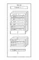
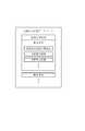
図30は、地図情報処理装置a1の更新指示情報記憶装置5内の更新指示情報格納部の構造を示す。更新指示情報格納部には、一つの更新指示情報管理データと一つ以上の更新指示情報0,1,2,..が格納される。更新指示情報管理データは、更新指示情報格納部に格納した更新指示情報0,1,2,..の管理を行うもので、各更新指示情報の格納位置(記憶装置内のアドレス)、データサイズ、取得状態等を示す更新指示情報管理レコードを有する。上記の更新指示情報の受信において、更新指示情報を取得できた場合は、プロセッサ6は、その更新指示情報を更新指示情報格納部に格納すると共にその格納位置、データサイズ、取得状態を取得済みを示すように設定した更新指示情報管理レコードを更新指示情報管理データに格納する。他方、通信障害等により更新指示情報を取得できなかった場合は、プロセッサ6は、要求した更新指示情報の更新指示情報ヘッダに相当するデータを更新指示情報として更新指示情報格納部に格納すると共にその格納位置、データサイズ、取得状態を未取得を示すように設定した更新指示情報管理レコードを更新指示情報管理データに格納する。従って、地図情報処理装置a1が更新指示情報要求を送信するたびに、更新指示情報格納部に格納される更新指示情報0,1,2,..は増加してゆく。
【0104】
更新指示情報が受信できた場合は、例えば、図10(a)の道路データフレームを図18の道路データフレームに更新するための更新操作レコードを有する図26(a)および図26(b)の表示系データフレームの更新指示情報、図13の経路計算系データフレームを図21の経路計算データフレームに更新するための更新操作レコードを有する図27(a)および図27(b)の経路計算系データの更新指示情報、ならびにこれらの更新指示情報を管理する更新指示情報管理レコードが更新指示情報格納部に格納される。
【0105】
次に、ステップST204では、ステップST202で決定した表示系データフレーム(更新前)をプロセッサ6は地図情報記憶装置4から取得する(読み出す)。例えば、図10(a)の道路データフレームを有する表示系データフレームを取得する。
【0106】
ステップST205では、プロセッサ6はステップST204で取得した表示系データフレームを更新する。具体的には、まずプロセッサ6は、更新指示情報記憶装置5の更新指示情報格納部より所要の領域(地域)の表示系データフレームの更新指示情報を取得し、その更新指示情報に関する更新指示情報管理レコード内の取得状態をチェックする。その更新指示情報に関する取得状態が取得済みを示していれば、プロセッサ6は取得した更新指示情報に従ってステップST204で取得した表示系データフレームを更新し、更新された表示系データフレームを更新指示情報記憶装置5の地図情報格納部に格納する。他方、更新指示情報に関する取得状態が未取得を示していれば、プロセッサ6はステップST204で取得した表示系データフレームをそのまま変更せずに、更新指示情報記憶装置5の地図情報格納部に格納する。
【0107】
従って、更新指示情報に関する取得状態が取得済みを示していれば、更新指示情報の更新操作レコードの指示に従い、図10(a)の道路データフレームを有する表示系データフレームに更新操作を施して、得られた更新済み表示系データフレームを更新指示情報記憶装置5の地図情報格納部に格納する。このとき地図情報格納部に格納された表示系データフレームの道路データフレームは、図18の道路データフレームに更新されている。つまり更新指示情報に従ってプロセッサ6が表示系データフレームを更新することによって、更新後の表示系データフレームを地図情報処理装置a1が得ることができる。また、更新指示情報に関する取得状態が未取得を示していれば、更新されていない図10(a)の道路データフレームを有する表示系データフレームが地図情報格納部に格納される。
【0108】
図31は、更新指示情報記憶装置5内の地図情報格納部の構造の一例を示す。地図情報格納部は、複数の領域(地域)にそれぞれ対応する複数の表示系データフレーム、および複数の領域にそれぞれ対応する複数の経路計算系データフレーム等を格納するとともに、これらの表示系データフレームおよび経路計算系データフレームを管理するための管理情報フレームを有する。管理情報フレームは、各表示系データフレーム、および各経路計算系データフレームの所在(更新指示情報記憶装置5内のアドレス)を示すデータを有する。本質的には、地図情報格納部の内容は、図4に示す地図情報記憶装置4内の地図情報と同じである。
【0109】
さらにステップST206では、ステップST202で決定した経路計算系データフレーム(更新前)をプロセッサ6は地図情報記憶装置4から取得する(読み出す)。例えば、図13の経路計算データフレームを有する経路計算系データフレームを取得する。
【0110】
ステップST207では、プロセッサ6はステップST206で取得した経路計算系データフレームを更新する。具体的には、まずプロセッサ6は、更新指示情報記憶装置5の更新指示情報格納部より所要の領域(地域)の経路計算系データフレームの更新指示情報を取得し、その更新指示情報に関する更新指示情報管理レコード内の取得状態をチェックする。その更新指示情報に関する取得状態が取得済みを示していれば、プロセッサ6は取得した更新指示情報に従ってステップST204で取得した経路計算系データフレームを更新し、更新された経路計算系データフレームを更新指示情報記憶装置5内の地図情報格納部に格納する。他方、更新指示状態に関する取得状態が未取得を示していれば、プロセッサ6はステップST204で取得した経路計算系データフレームをそのまま変更せずに、更新指示情報記憶装置5の地図情報格納部に格納する。
【0111】
従って、更新指示情報に関する取得状態が取得済みを示していれば、更新指示情報の更新操作レコードの指示に従い、図13の経路計算データフレームを有する経路計算系データフレームに更新操作を施して、得られた更新済み経路計算系データフレームを更新指示情報記憶装置5の地図情報格納部に格納する。このとき地図情報格納部に格納された経路計算系データフレームの経路計算データフレームは、図21の経路計算データフレームに更新されている。つまり更新指示情報に従ってプロセッサ6が経路計算系データフレームを更新することによって、更新後の経路計算系データフレームを地図情報処理装置a1が得ることができる。また、更新指示情報に関する取得状態が未取得を示していれば、更新されていない図13の経路計算データフレームを有する経路計算系データフレームが地図情報格納部に格納される。
【0112】
ステップST208では、ナビゲーション処理サブルーティンを実行し、その終了後、動作はステップST200に戻って繰り返される。ナビゲーション処理は、ステップST205、ステップST207で更新指示情報記憶装置5の地図情報格納部に格納された表示系データフレーム、経路計算系データフレームを用い、ステップST200で得られた指示信号に従って行う。
【0113】
図32はステップST208のナビゲーション処理として地図表示、経路計算および経路表示を行う際の動作を示すフローチャートである。
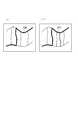
まず、ステップST300では、更新指示情報記憶装置5の地図情報格納部に格納された所要領域の表示系データフレームを用いてプロセッサ6は出力装置7の表示装置に地図画面を表示する。この表示系データフレームが更新されたものであるならば図18の道路データフレームを有しているため、図33(b)に示すように図15の道路が表示され、表示系データフレームが更新されたものでないならば図10(a)の道路データフレームを有しているため図33(a)に示すように図5の道路が表示される。
【0114】
ステップST301では、更新指示情報記憶装置5の地図情報格納部に格納された所要領域の経路計算系データフレームの経路計算データフレームを用いて、プロセッサ6はダイクストラ法等による経路計算を行う。この経路計算により出発地から目的地までの所要時間等のコストが最小となる経路を求め、その出発地から目的地に至るまでに経由するノードのノード番号をノードの経由順に並べた経由ノード情報を得る。これらのノードを経由ノードと呼ぶ。
【0115】
ステップST302では、ステップST301で求めた経由ノード情報に基づいて、所要領域の経路計算系データフレームの経路計算データフレームから、好適な経路を構成するリンクに関する情報を抽出して、これらに基づいて経路情報を作成する。
【0116】
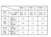
図34は地図情報処理装置a1で作成される経路情報の構造を示す。経路情報は、経路ノード間を結ぶ経路計算系リンクに対応する表示系リンクのリンク識別番号を示す経路リンクレコードの並びとその経路リンクレコードの数を示す経路リンクレコード数を有する。経路リンクレコードは、図14および図22に示す接続レコードから抽出された副リンク識別情報有無情報、対応リンク識別情報、および対応副リンク識別情報を有する。対応リンク識別情報は、当該経路計算系リンクの対応する表示系リンクのリンク識別番号の範囲を示すために、先頭リンク識別番号と終端リンク識別番号を有する。対応副リンク識別情報は、代替リンクの副リンク識別番号の範囲を示すために、先頭副リンク識別番号と終端副リンク識別番号を有する。対応副リンク識別有無情報は、対応副リンク識別情報の先頭対応副リンク識別番号、終端対応副リンク識別番号の有無を示す。
【0117】
各経路ノードについて、経路ノードのノードレコード中から次に経由する経路ノードを隣接ノードとする接続レコードを見つけ、その接続レコード中の対応対応リンク識別情報、副リンク識別情報を抽出して、これらを経路リンクレコードの対応対応リンク識別情報、副リンク識別情報に設定することにより経路情報を得る。
【0118】
図35および図36は、経路情報の内容の具体例を示す。図35は、更新された経路計算データフレームに基づいて作成された経路情報の内容であり、経路計算の結果得られた経路が、図17のノードNr3,Nr4,Nr1,Nr6,Nr2を経由することを示す。対応リンク識別情報および対応副リンク識別情報は、図17の経路計算系リンクLr2,Lr4,Lr1’,Lr1”に対応する図16の表示系リンクのリンク識別番号を示している。この結果、図16の表示系リンクLd5,Ld6,Ld11,Ld2,Ld3’,Ld3”,Ld4が好適な経路に該当していることが分かる。
【0119】
図36は、未更新の経路計算データフレームに基づいて作成された経路情報の内容であり、経路計算の結果得られた経路が、図9のノードNr3,Nr4,Nr1,Nr2を経由することを示す。対応リンク識別情報および対応副リンク識別情報は、図9の経路計算系リンクLr2,Lr4,Lr1に対応する図8の表示系リンクのリンク識別番号を示している。この結果、図8のリンクLd5,Ld6,Ld11,Ld2,Ld3,Ld4が好適な経路に該当していることが分かる。
【0120】
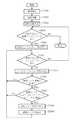
ステップST303では、経路情報内に未取り出しの経路リンクレコードがあるか否かをプロセッサ6が判断する。後述するステップST304のために経路リンクレコードが全て取り出された場合には、ステップST303の判断は否定的になり、動作は終了する(すなわち図29のステップST208のナビゲーション処理が終了する)。他方、経路情報内に未取り出しの経路リンクレコードがある場合には、動作はステップST304へ進む。
【0121】
ステップST304では、経路情報から一つの未取り出しの経路リンクレコードをプロセッサ6が取り出す。この取り出しは、取り出された各経路リンクレコードに基づいて、表示系リンクの形状を特定して表示装置に表示させるためである。
【0122】
ステップST305では、更新指示情報記憶装置5の地図情報格納部に格納された所要領域の表示系データフレームの道路データフレーム内に未取り出しのノードリンクレコードがあるか否かをプロセッサ6が判断する。後述するステップST306のためにノードリンクレコードが全て取り出された場合には、ステップST305の判断は否定的になり、動作はステップST303に戻る。他方、所要領域の表示系データフレームの道路データフレーム内に未取り出しのノードリンクレコードがある場合には、動作はステップST306へ進む。
【0123】
ステップST306では、更新指示情報記憶装置5の地図情報格納部に格納された所要領域の表示系データフレームの道路データフレームから一つの未取り出しのノードリンクレコードをプロセッサ6が取り出す。
【0124】
ステップST307では、ステップST304で既に取り出された経路リンクレコードが、ステップST306で取り出されたノードリンクレコードに関連するか否か判断する。より具体的には、上述したリンク識別番号および総合リンク識別番号のデータ表記上の大小関係に基づいて、ステップST306で取り出したノードリンクレコードのリンク識別情報および副リンク識別情報により示されるリンク識別番号の範囲(以下、範囲Aと呼ぶ)が、ステップST304で取り出した経路リンクレコードの対応リンク識別情報および対応副リンク識別情報によって示されるリンク識別番号の範囲(以下、範囲Bと呼ぶ)に含まれるか否かを判定する。範囲Aが範囲Bに含まれていれば、動作はステップST308に進み、含まれていなければステップST305へ戻る。
【0125】
上記処理により、経路情報中の各経路リンクレコードに指定されたリンク識別番号の範囲Bが付与されたリンクと、表示系データフレーム中の所要のノードリンクレコードに指定されたリンク識別番号の範囲Aが付与されたリンクを対応付ける。次に、ステップST308では、対応付けられたノードリンクレコードのノード座標、補間点座標をプロセッサ6が取得する。つまり、ステップST304で経路情報から取り出した経路リンクレコードに対応する表示系リンクの形状を特定する。
【0126】
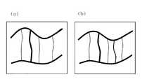
ステップST309では、ステップST308で取得したノード座標、補間点座標を用いて当該経路リンクの形状を、ステップST300で出力装置7の表示装置に表示した地図画面上に表示する。図37(a)または図37(b)に示すように、この好適経路リンクは、通常の道路を表示する線よりも太い線で、道路に重ねて表示する。
【0127】
ステップST309の後、動作はステップST303に戻り、以降、ステップST303〜309を繰り返し、次の経路リンクレコードに基づいて経路リンクを表示してゆき、最終的に図37(a)または図37(b)に示すような経路を地図画面上に表示する。
【0128】
この実施の形態では、所要領域の更新指示情報の受信状態すなわち取得状態により、地図情報処理装置a1においては、所要領域の経路計算データフレームおよび表示系データフレームの更新状態が同じであったり異なったりする。すなわち、以下の4つの状態が存在しうる。
【0129】
第1の状態では、地図情報処理装置a1で所要領域の経路計算データフレームおよび表示系データフレームが共に更新されている。更新指示情報に従って、例えば図21に示す経路計算データフレーム、および図18に示す道路データフレームが地図情報処理装置a1で作成され、更新指示情報記憶装置5の地図情報格納部に格納されている。この場合、ステップST307で用いるリンク識別番号の範囲A,Bが共に更新後のものとなっている。
【0130】
第2の状態では、所要領域の経路計算データフレームが更新されるが、表示系データフレームが更新されていない。例えば、図21に示す更新後の経路計算データフレームと、図10に示す旧版の道路データフレームが更新指示情報記憶装置5の地図情報格納部に格納されている。この場合、リンク識別番号の範囲Aが更新後、範囲Bが更新前(旧版)のものとなっている。
【0131】
第3の状態では、所要領域の経路計算データフレームが更新されないが、表示系データフレームが更新される。例えば、図13に示す旧版の経路計算データフレームと、図18に示す更新後の道路データフレームが更新指示情報記憶装置5の地図情報格納部に格納されている。この場合、リンク識別番号の範囲Aが更新前、範囲Bが更新後のものとなっている。
【0132】
第4の状態では、所要領域の経路計算データフレームおよび表示系データフレームが共に更新されていない。例えば、図13に示す旧版の経路計算データフレームと、図10に示す旧版の道路データフレームが更新指示情報記憶装置5の地図情報格納部に格納されている。この場合、リンク識別番号の範囲A,Bが共に更新前のものとなっている。
【0133】
上述したステップST307の判定では、経路リンクレコードとノードリンクレコードの関連付けは具体的には以下のように行われる。
上記の第1の状態で、更新された経路計算データフレームに基づいて図35に示す経路情報が作成されていると想定する。経路リンクレコード0については、リンク識別番号の範囲が105〜106にあるリンク識別番号を持つノードリンクレコードは図20のリンク列レコードMR1’のノードリンクレコードNRL10,NLR11(図16のLd5,Ld6に対応)である。経路リンクレコード1については、リンク識別番号の範囲が111〜111にあるリンク識別番号を持つノードリンクレコードは図12のリンク列レコードMR3のノードリンクレコードNRL30(図16のLd11に対応)である。経路リンクレコード2については、リンク識別番号の範囲が102〜103:127にあるリンク識別番号を持つノードリンクレコードは図19のリンク列レコードMR0’のノードリンクレコードNRL02,NLR03’(図16のLd2,Ld3’に対応)である。経路リンクレコード3については、リンク識別番号の範囲が103:128〜104にあるリンク識別番号を持つノードリンクレコードは図19のリンク列レコードMR0’のノードリンクレコードNRL04I,NLR04(図16のLd3”,Ld4に対応)である。
従って、図16のリンクLd5,Ld6,Ld11,Ld2,Ld3’,Ld3”,Ld4に該当する好適経路リンクが表示画面に表示される。この表示結果が図37(b)に示されている。つまり、変更後の道路の表示上に、好適経路リンクが重ねて表示される。
【0134】
上記の第2の状態で、更新された経路計算データフレームに基づいて図35に示す経路情報が作成されていると想定する。経路リンクレコード0については、リンク識別番号の範囲が105〜106にあるリンク識別番号を持つノードリンクレコードは図12のリンク列レコードMR1のノードリンクレコードNRL10,NLR11(図8のLd5,Ld6に対応)である。経路リンクレコード1については、リンク識別番号の範囲が111〜111にあるリンク識別番号を持つノードリンクレコードは図12のリンク列レコードMR3のノードリンクレコードNRL30(図8のLd11に対応)である。経路リンクレコード2については、リンク識別番号の範囲が102〜103:127にあるリンク識別番号を持つノードリンクレコードは図11のリンク列レコードMR0のノードリンクレコードNRL02,NLR03(図8のLd2,Ld3に対応)である。経路リンクレコード3については、リンク識別番号の範囲が103:128〜104にあるリンク識別番号を持つノードリンクレコードは図19のリンク列レコードMR0’のノードリンクレコードNRL03,NLR04(図8のLd3,Ld4に対応)である。
従って、図8のリンクLd5,Ld6,Ld11,Ld2,Ld3,Ld4に該当する好適経路リンクが表示画面に表示される。この表示結果が図37(a)に示されている。つまり、変更前の道路の表示上に、好適経路リンクが重ねて表示される。
【0135】
第3の状態で、未更新の経路計算データフレームに基づいて図36に示す経路情報が作成されていると想定する。経路リンクレコード0については、リンク識別番号の範囲が105〜106にあるリンク識別番号を持つノードリンクレコードは図20のリンク列レコードMR1’のノードリンクレコードNRL10,NLR11(図16のLd5,Ld6に対応)である。経路リンクレコード1については、リンク識別番号の範囲が111〜111にあるリンク識別番号を持つノードリンクレコードは図12のリンク列レコードMR3のノードリンクレコードNRL30(図16のLd11に対応)である。経路リンクレコード2については、リンク識別番号の範囲が102〜104にあるリンク識別番号を持つノードリンクレコードは図19のリンク列レコードMR0’のノードリンクレコードNRL02,NLR03’,NLR04I,NLR04(図16のLd2,Ld3’,Ld3”,Ld4に対応)である。
従って、図16のリンクLd5,Ld6,Ld11,Ld2,Ld3’,Ld3”,Ld4に該当する好適経路リンクが表示画面に表示される。この表示結果が図37(b)に示されている。つまり、変更後の道路の表示上に、好適経路リンクが重ねて表示される。
【0136】
上記第4の状態で、未更新の経路計算データフレームに基づいて図36に示す経路情報が作成されていると想定する。経路リンクレコード0については、リンク識別番号の範囲が105〜106にあるリンク識別番号を持つノードリンクレコードは図12のリンク列レコードMR1のノードリンクレコードNRL10,NLR11(図8のLd5,Ld6に対応)である。経路リンクレコード1については、リンク識別番号の範囲が111〜111にあるリンク識別番号を持つノードリンクレコードは図12のリンク列レコードMR3のノードリンクレコードNRL30(図8のLd11に対応)である。経路リンクレコード2については、リンク識別番号の範囲が102〜104にあるリンク識別番号を持つノードリンクレコードは、図12のリンク列レコードMR0のノードリンクレコードNRL02,NLR03,NLR04(図8のLd2,Ld3,Ld4に対応)である。
従って、図8のリンクLd5,Ld6,Ld11,Ld2,Ld3,Ld4に該当する好適経路リンクが表示画面に表示される。この表示結果が図37(a)に示されている。つまり、変更前の道路の表示上に、好適経路リンクが重ねて表示される。
【0137】
以上の第2の状態および第3の状態では、地図情報処理装置a1では版が異なる表示系データフレームと経路計算系データフレームを記憶しているが、上記のように、この実施の形態では、表示系データフレームと経路計算系データフレームの版が異なっていても、リンクの対応付けが可能である。よって、地図情報処理装置a1では、片方のデータフレームしか取得できなくても正しく経路を表示することが可能である。
【0138】
以上のように、この実施の形態1によれば、地図情報のデータ構造において、地図表示用の道路データ部分(道路データフレーム)が、元リンクを表すリンク識別情報と、代替リンクを表すために使用される副リンク識別情報とを有しており、各リンクについて、リンク識別情報と副リンク識別情報が対応付けられて、地図情報処理装置(コンピュータ、論理回路またはそれらの組み合わせ)によって元リンクと代替リンクの関連付けが可能にされている(図11、図12、図19および図20参照)。また、経路計算用の経路計算データ部分(経路計算データフレーム)も、元リンクを表すリンク識別情報(対応リンク識別情報)と、代替リンクを表すために使用される副リンク識別情報(対応副リンク識別情報)とを有しており、各リンクについて、リンク識別情報と副リンク識別情報が対応付けられて、地図情報処理装置によって元リンクと代替リンクの関連付けが可能にされている(図14、図22および図23参照)。従って、道路データフレームの版と経路計算データフレームの版が異なっていても、新設された代替リンクと元リンクの対応づけが可能である。よって、地図情報処理装置a1では、片方のデータフレームしか更新できなくても正しく経路を表示することが可能である。
【0139】
また、更新指示情報のデータ構造において、代替リンクに関連する情報部分を地図情報に追加させる更新操作レコードが、元リンクを表すリンク識別情報と、当該代替リンクを表す副リンク識別情報とを有するので(図26(b)および図27(b)参照)、上記の地図情報の道路データフレームの更新にも経路計算データフレームの更新にも適しており、更新指示情報を受信した地図情報処理装置a1ではプロセッサ6が更新操作レコードの指定に従って自動的に該当レコードを更新できる。
【0140】
この実施の形態では、更新指示情報のデータ構造において、各更新操作レコードが更新対象種別および更新対象位置を地図情報処理装置(コンピュータ、論理回路またはそれらの組み合わせ)に指定するので、更新が必要な更新データ(リンク列ヘッダ、ノードリンクレコード、ノードレコードまたは接続レコード)だけを地図情報処理装置a1に与えて更新させることができる。すなわち更新指示情報のサイズを小さくすることができる。
【0141】
実施の形態2.
次に、この発明の実施の形態2を説明する。図1から図3に示された地図情報処理装置a1および地図情報提供装置a2は実施の形態2でも使用される。実施の形態2における地図情報処理装置a1および地図情報提供装置a2の各構成要素の機能は、実施の形態1における機能と基本的に同様である。また、地図情報処理装置a1で使用する地図情報(図4)の内容も、実施の形態1における地図情報の内容と基本的に類似し、図10から図14を参照して上述した表示系データフレームおよび経路計算系データフレームと同様のデータフレームを有する。
【0142】
ただし、表示系データフレームの道路データフレーム中のリンク列レコードの構造は、図11に示すものと異なる。図38は実施の形態2に係るリンク列レコードの構造を示す。図38のリンク列レコードにおいては、ノードリンクヘッダは、対応するリンクの補間点の数および副リンク識別有無情報に加えて、対応するリンクが無効であるか有効であるかを示す無効リンク情報を格納する。初版の地図情報において、無効リンク情報にはすべて有効とする値が格納される。
【0143】
この実施の形態についても、図5から図9に示す地図の表現に関連付けて説明する。従って、図38に示すリンク列レコードも図5、図6および図8に示す地図に基づいて作成されており、無効リンク情報以外の構造および数値は、図11に示すリンク列レコードと同じである。
【0144】
次に、道路網の変更または現実の道路に即した地図情報の充足のための地図情報の更新を説明する。実施の形態1に関する説明と同様に、図15に示すように、一つの道路6が新たに記述されると想定する。図39は、図16と同様の図であって、表示系データフレームの更新にあたって、図15の変更された道路0〜6の接続関係を示すために仮想的に割り振られるノード、リンク、リンク列、リンク識別番号を示す。
【0145】
図示のように、新設されたかまたは新規に地図情報に記述すべき道路6に対応するリンク列6が設けられており、リンク列6に接続する新たなリンク列7,8が設けられている。リンク列7は、図8の元リンクLd3と同じ道路部分r0(図5参照)に対応しており、道路部分r00,r01(図15参照)に対応する代替リンクLd3’,Ld3”を有する。リンク列8は、図8の元リンクLd8と同じ道路部分r1(図5参照)に対応しており、道路部分r10,r11(図15参照)に対応する代替リンクLd8’,Ld8”を有する。
【0146】
そして、変更前の道路網中の道路0の道路部分r0に対応するリンクLd3の両端のノードNd3,Nd4に、リンク列7がその両端のノードNd3”,Nd4”を介して接続し、同様に変更前の道路1の道路部分r1に対応するリンクLd8の両端のノードNd9,Nd10に、リンク列8がその両端のノードNd3”,Nd4”を介して接続する。また、リンク列6の先頭のノードNd12’に、リンク列7がそのノードNd12を介して接続し、リンク列6の終端のノードNd13’に、リンク列8がそのノードNd13を介して接続する。また、後で述べる方法により、リンクLd3,Ld8は無効なリンクとみなされる、すなわちこれらのリンクLd3,Ld8が存在しないものとみなされるようにしている。尚、リンクLd3’,Ld3”,Ld8’,Ld8”には、それぞれ図16のリンクLd3’,Ld3”,Ld8’,Ld8”と同一のリンク識別番号を付与している。
【0147】
図40は、図39の道路網を表す道路データフレームを示す。道路データフレームは、図10(a)の道路データヘッダと同様の道路データヘッダと、複数のリンク列レコードMR0S〜MR8Sを有する。リンク列レコードMR0S〜MR8Sは、図39のリンク列0〜8にそれぞれ対応するように設けられており、対応するリンク列に関する情報が格納される。
【0148】
図41は図40のリンク列レコードMR0Sの内容を示す。図41中のリンク列レコードの各ノードリンクレコードの構造は、図38に示す元のリンク列レコードの各ノードリンクレコードの構造と同じである。リンク列レコードMR0Sは、図38のリンク列レコードMR0を以下のように更新したものである。
図41中の改変されたノードリンクレコードNLR03S(ノードNd3と元リンクLd3に対応する)は、元のノードリンクレコードNLR03の無効リンク情報を無効とするとともに、ノードNd3の接続先のノードがリンク列7のノードNd3”を示すように交差情報を変更したものである。また、改変されたノードリンクレコードNLR04S(ノードNd4とリンクLd4に対応する)は、リンクLd3,Ld4の間のノードNd4の接続先のノードがリンク列7のノードNd4”を示すように元のノードリンクレコードNLR04の交差情報を変更したものである。
【0149】
図42は図40のリンク列レコードMR7S(新設されたリンク列7に対応する)の内容を示す。リンク列レコードMR7SのノードリンクレコードNLR70S,NLR71S,NLR72Sは、リンク列7を順方向にたどったときに出現するノードとリンクの対(Nd3”,Ld3’)、(Nd12,Ld3”)、(Nd4”,なし)にそれぞれ対応する。リンク列レコードMR7Sでは、ノードリンクレコードの無効リンク情報をすべて有効にし、リンクLd3’,リンクLd3”が有効であることを示す。リンク列7のノードNd3”,Nd12,Nd4”に対応するノードリンクレコードNLR70S,NLR71S,NLR72Sの交差情報は、接続先がそれぞれリンク列4のノードNd3’、リンク列6のノードNd12’、リンク列5のノードNd4’となるように設定する。また、リンクLd3’,Ld3”のリンク識別情報としてノードリンクレコードNLR70S,NLR71SにリンクLd3と同じリンク識別番号103を設定する。さらに、リンクLd3’,Ld3”の副リンク識別情報としてノードリンクレコードNLR70S,NLR71Sにそれぞれ0,128を設定している。
【0150】
図41に示すノードリンクレコードNLR03Sの交差情報のリンク列番号7、ノードリンク番号0から、図42に示すノードリンクレコードNLR70Sが導かれ、逆にノードリンクレコードNLR70Sのリンク列番号0、ノードリンク番号3からノードリンクレコードNLR03Sが導かれる。また、図41に示すノードリンクレコードNLR04Sの交差情報のリンク列番号7、ノードリンク番号2から、図42に示すノードリンクレコードNLR72Sが導かれ、逆にノードリンクレコードNLR72Sのリンク列番号0、ノードリンク番号4からノードリンクレコードNLR04Sが導かれる。従って、元リンクLd3が代替リンクLd3’,リンクLd3”にノードNd3(Nd3”)およびノードNd4(Nd4”)で交差することが分かる。
【0151】
図43は図40のリンク列レコードMR6S(新設されたリンク列6に対応する)の内容を示す。リンク列レコードMR6SのノードリンクレコードNLR60S,NLR61Sは、リンク列6を順方向にたどったときに出現するノードとリンクの対(Nd12’,Ld14)、(Nd13’,なし)にそれぞれ対応する。リンク列レコードMR6Sでは、ノードリンクレコードの無効リンク情報をすべて有効にし、リンクLd14が有効であることを示す。リンク列7のノードNd12’,Nd13’に対応するノードリンクレコードNLR60S,NLR61Sの交差情報は、接続先がそれぞれリンク列7のノードNd12,リンク列8のノードNd13となるように設定する。また、リンクLd14のリンク識別情報としてノードリンクレコードNLR60Sにリンク識別番号114を設定している。
【0152】
図40のリンク列レコードMR1S(リンク列1に対応する),リンク列レコードMR8S(新設されたリンク列8に対応する)も、上記と同様にして図39の道路網を示すように設定される。
【0153】
以上、更新後の地図情報の表示系データフレームは、図39から図43を参照しながら説明した基本原理に従ったデータ構造を有する。経路計算データフレームを有する経路計算系データフレームは、実施の形態1と同様のデータ構造を有しており、更新後の経路計算系データフレームも実施の形態1と同様のデータ構造を有する(図17、図21〜図23参照)。
【0154】
上記のように道路データの既存のリンク列レコードにおいては、元リンク(例えばLd3)を直列に連なった代替リンク(例えばLd3’,Ld3”)で置換するような更新で、元リンクのノードリンクレコード(例えばNLR03)の削除も代替リンクのノードリンクレコードの挿入も行わない。従って、図39のリンク列0のノードNd4,Nd5およびリンク列1のノードNd10,Nd11に対応する図40のリンク列レコードMR0S,MR1Sにおけるノードリンクレコード(例えばNLR04S,NLR05)のノードリンクレコード番号は、図10(a)のリンク列レコードMR0,MR1におけるノードリンクレコード番号と同じとなる。従って、これらのノードリンクレコード番号を使用している交差情報を持つ図40のリンク列レコードMR2S〜MR5Sには、図10(a)のリンク列レコードMR2〜MR5のノードリンク番号と同一値が与えられる。すなわち、図39のリンク列0,リンク列1に関する更新は、リンク列2〜リンク列5に関するリンク列レコードMR2〜MR5に影響を及ぼさず、対応道路が変更されていないリンク列2〜リンク列5のリンク列レコードMR2〜MR5の更新を必要としない。例えば、図38のノードリンクレコードNLR50のリンク列番号0とノードリンク番号4から図41のノードリンクレコードNLR04Sが導かれ、ノードリンクレコードNLR04Sのリンク列番号7とノードリンク番号2から図42のノードリンクレコードNLR72Sが導かれるので、交差情報の確実性も維持される。
【0155】
従来の地図情報のデータ構造については、道路の新設等に伴い、データの更新が必要な場合には、更新すべき情報量が多く、各使用者の地図情報処理装置でも更新に要する時間が増加するおそれがある。例えば、道路が新設されたり地図情報上で既存の道路を新規に表現したりする場合には、道路地図表示用のデータにおいて、道路を新規に表現するリンク列レコードの追加に伴い、その道路のリンクが交差する元リンクが代替リンクに分割されることから、順方向に進んで元リンクの後に登場するすべてのノードとリンクに関するノードリンクレコードを示すノードリンク番号の振り直しが必要となると考えられる。そして一つのノードリンクレコードのノードリンク番号を修正すると、そのノードリンクレコードに対応するリンクに交差する他のリンクについてのノードリンクレコードでも、リンクが変更されていないのに、交差情報中のノードリンク番号を改変する必要があると考えられる。すなわち、新たに表現する道路に直接的に関連する情報を追加するだけでなく、これに間接的に関連する多大な量の情報を変更する必要がある。
【0156】
しかし、この実施の形態2では、対応道路が変更されていないリンク列のリンク列レコードの更新を必要としない。従って、更新すべき情報量が少なくて済み、地図情報処理装置にとって更新処理の手間が少ない。上記の例では、表示系データフレームの道路データフレーム中の更新処理が必要なのは、道路0,1,6,7,8に対応するリンク列レコードMR0S,MR1S,MR6S,MR7S,MR8Sである。
【0157】
更新された地図情報を地図情報処理装置a1が取得できれば、その地図情報処理装置a1でも最新の実際の道路についての地図表示、マップマッチングおよび経路計算が可能である。更新された地図情報を地図情報処理装置a1が取得するための方法として、この実施の形態でも、地図情報提供装置a2が地図情報処理装置a1に更新指示情報を送信する。更新指示情報に従って地図情報処理装置a1が元の地図情報を変更すると、更新された地図情報を得ることができる(つまり個々の地図情報処理装置a1でも地図情報を更新できる)。
【0158】
次に、地図情報処理装置a1が地図情報を更新する方法を説明する。実施の形態1と同様に、地図情報提供装置a2の更新指示情報記憶装置11(図3参照)には、図24に示す構造の更新指示情報データベースが格納されている。地図情報提供業者は更新指示情報を更新指示情報データベースに追加するときに、追加に伴い必要な改変を更新指示情報データベースの版数管理情報に行う。
【0159】
実施の形態1と同様に、更新指示情報データベースの各版別情報は、表示系データフレームのための更新指示情報および経路計算系データフレームのための更新指示情報を有する。表示系データフレームのための更新指示情報は、地図情報処理装置a1のプロセッサ6に対して、図10の旧版の道路データフレームを図40の新版の道路データフレームに更新させる。表示系データフレームのための更新指示情報は図44に示されている。一方、経路計算系データフレームのための更新指示情報は、地図情報処理装置a1のプロセッサ6に対して、図13の旧版の経路計算データフレームを図21の新版の経路計算データフレームに更新させる。経路計算系データフレームのための更新指示情報は、図27(a)および図27(b)に示された構造を有する。
【0160】
図44を参照し、図10の旧版の道路データフレームを図40の新版の道路データフレームに更新させるための表示系データフレームの更新用の更新指示情報を説明する。この更新指示情報は実施の形態1で用いた図25の更新指示情報と同一データ構造を有する。図中の更新操作レコード群OPDS1は、表示系データフレーム中の道路データヘッダを更新するための更新操作レコードの集合である。更新操作レコード群OPDS2は、図10(a)のリンク列レコードMR0を図40のリンク列レコードMR0Sに更新するための更新操作レコードの集合である。更新操作レコード群OPDS3は、図10(a)のリンク列レコードMR1を図40のリンク列レコードMR1Sに更新するための更新操作レコードの集合である。更新操作レコード群OPDS4は、図40のリンク列レコードMR6S,MR7S,MR8Sを追加するための更新操作レコードの集合である。
【0161】
リンク列レコードMR0をリンク列レコードMR0Sに更新するための更新操作レコード群OPDS2は、図38のリンク列レコードMR0内の元リンクLd3に対応するノードリンクレコードNLR03の無効リンク情報を無効を示すように書き換える操作を指定し、元リンクLd3の両端のノードに対応するノードリンクレコードNL03,NL04の交差情報を、元リンクLd3の両端のノードの接続先が新リンク列7の両端のノードを示すように変更する操作を指定する。つまり、更新操作レコード群OPDS2は、リンク列レコードMR0のノードリンクレコードNL03,NL04の各々をノードリンクレコードNL03S,NL04Sに置換(上書き)するための二つのリンク列レコードと、旧リンク列ヘッダを新リンク列ヘッダに置換するためのリンク列レコードを有する。これらのリンク列レコードの形式は、実施の形態1の図26(b)に関する説明により当業者であれば理解できるであろう。
【0162】
同様に、リンク列レコードMR1をリンク列レコードMR1Sに更新するための更新操作レコード群OPDS3は、図38のリンク列レコードMR1内のリンクLd8に対応するノードリンクレコードの無効リンク情報を無効に変更する操作を指定し、リンクLd8の両端のノードに対応するノードリンクレコードの交差情報を、リンクLd8の両端のノードの接続先がリンク列8の両端のノードを示すように変更する操作を指定する。
【0163】
リンク列レコードMR6S,MR7S,MR8Sを追加する更新操作レコード群OPDS4は、新たなリンク列レコードMR6S,MR7S,MR8Sを追加する更新操作レコードと、それらの内容を追加する更新操作レコードを有する。例えば、代替リンクLd3’,Ld3”を表現するノードリンクレコードNLR70S〜NLR72Sを追加させる指示を含む更新操作レコードは、代替リンクLd3’,Ld3”が地図表示上有効であることを示す無効リンク情報と、代替リンクLd3’,Ld3”が元リンクLd3に交差することを示す交差情報を対応ノードリンクレコードNLR70S〜NLR72Sが持つようにする指示を含む。
【0164】
上述の通り、直列に連なった代替リンクで元リンクを置換するような更新において、対応道路が変更されていないリンク列2〜リンク列5のリンク列レコードMR2〜MR5の更新を必要とせず、表示系データフレームの道路データフレーム中の更新処理が必要なのは、道路0,1,6,7,8に対応するリンク列レコードMR0S,MR1S,MR6S,MR7S,MR8Sである。従って、更新指示情報には、リンク列2〜リンク列5に関するリンク列レコードMR2〜MR5を更新するための更新指示情報は不要であり、そのための更新操作レコードは含まれない。
【0165】
また、経路計算系データフレームの経路計算データフレームは実施の形態1と同様に更新されるので、経路計算系データフレームのための更新指示情報は実施の形態1と同様でよい(図27(a)および図27(b)参照)。
【0166】
実施の形態2においても、表示系データフレームのための更新指示情報および経路計算系データフレームのための更新指示情報は、図28に示すように実施の形態1と同様に、地図情報処理装置a1からの要求に従って、地図情報提供装置a2から地図情報処理装置a1に個別に提供される。このようにして元リンクを置換する代替リンクを設ける更新について元リンクが無効であることを示す無効リンク情報と、代替リンクを有するリンク列を追加するためのリンク列レコードMR7S,MR8Sと、そのリンク列と元リンクを接続するための交差情報を含む更新指示情報を地図情報処理装置へ提供する。更新指示情報には対応道路が変更されていないリンク列に関する情報が含まれていないため、更新指示情報の増大を来たさず、より短い時間で更新指示情報を送信できる。
【0167】
実施の形態2における地図情報処理装置a1のプロセッサ6の動作は、図29を参照して説明した実施の形態1の地図情報処理装置a1のプロセッサ6の動作とほぼ同様である(ただし後述のようにステップST208のナビゲーション処理が異なる)。従って、ステップST203で受信した表示系データフレームのための更新指示情報に従って、プロセッサ6は、図10の旧版の道路データフレームを有する表示系データフレームに更新処理を施し、その結果得られた図40の最新版の道路データフレームを含む表示系データフレームを更新指示情報記憶装置5の地図情報格納部にステップST205で格納する。また、ステップST203で受信した経路計算系データフレームのための更新指示情報に従って、プロセッサ6は、図13の旧版の経路計算データフレームを有する経路計算系データフレームに更新処理を施し、その結果得られた図21の最新版の経路計算データフレームを含む経路計算系データフレームを更新指示情報記憶装置5の地図情報格納部にステップST206で格納する。
【0168】
更新指示情報の更新操作レコードは、更新すべきデータ部分とそれらの取り扱い方式を指定しているので、かかる更新操作レコードの指示に従った更新操作を行うことにより、地図情報処理装置a1は地図情報の更新を行うことができる。更新指示情報には対応道路が変更されていないリンク列に関する情報が含まれていないため、地図情報処理装置a1においても、更新指示情報の受信の時間を短縮でき、更新処理量を少なくでき、更新処理の時間も短縮できる。
【0169】
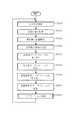
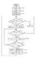
次に、実施の形態2によるナビゲーション処理(図29のステップST208)について図45を参照しながら説明する。図45のフローチャートは、ステップST306とステップST307の間に追加されたステップST400を有する点で図32のフローチャートと異なる。他の処理は実施の形態1と同様である。
【0170】
ステップST400では、ステップST306で取り出したノードリンクレコードの無効リンク情報をプロセッサ6がチェックする。無効リンク情報が無効を示していれば、動作はステップST305へ戻る。これは、当該表示系リンクが無効であるため経路表示に役立たないからである。他方、無効リンク情報が有効を示していれば、動作はステップST307に進み、ステップST304で既に取り出された経路リンクレコードが、ステップST306で取り出されたノードリンクレコードに関連するか否か判断する。従って、代替リンクで置換された元リンクは経路として表示されず、その代わりに、代替リンクに対応する経路が表示される。
【0171】
この実施の形態でも、所要領域の更新指示情報の受信状態すなわち取得状態により、地図情報処理装置a1においては、所要領域の経路計算データフレームおよび表示系データフレームの更新状態が同じであったり異なったりする。すなわち、以下の4つの状態が存在しうる。
【0172】
第1の状態では、地図情報処理装置a1で所要領域の経路計算データフレームおよび表示系データフレームが共に更新されている。更新指示情報に従って、例えば図21に示す経路計算データフレーム、および図40に示す道路データフレームが地図情報処理装置a1で作成され、更新指示情報記憶装置5の地図情報格納部に格納されている。この場合、ステップST307で用いるリンク識別番号の範囲A,Bが共に更新後のものとなっている。従って、更新後の経路計算データフレームおよび表示系データフレームに基づいて、経路が正しく表示される。この表示結果が図37(b)に示されている。つまり、変更後の道路の表示上に、好適経路リンクが重ねて表示される。
【0173】
第2の状態では、所要領域の経路計算データフレームが更新されるが、表示系データフレームが更新されていない。例えば、図21に示す更新後の経路計算データフレームと、図10に示す旧版の道路データフレームが更新指示情報記憶装置5の地図情報格納部に格納されている。この場合、リンク識別番号の範囲Aが更新後、範囲Bが更新前(旧版)のものとなっている。しかし、更新前のリンク識別番号の範囲と更新後のリンク識別番号の範囲の対応付けが可能であるから、更新後の経路計算データフレームおよび更新前の表示系データフレームに基づいて、経路が正しく表示される。この表示結果が図37(a)に示されている。つまり、変更前の道路の表示上に、好適経路リンクが重ねて表示される。
【0174】
第3の状態では、所要領域の経路計算データフレームが更新されないが、表示系データフレームが更新される。例えば、図13に示す旧版の経路計算データフレームと、図40に示す更新後の道路データフレームが更新指示情報記憶装置5の地図情報格納部に格納されている。この場合、リンク識別番号の範囲Aが更新前、範囲Bが更新後のものとなっている。しかし、更新前のリンク識別番号の範囲と更新後のリンク識別番号の範囲の対応付けが可能であるから、更新前の経路計算データフレームおよび更新後の表示系データフレームに基づいて、経路が正しく表示される。この表示結果が図37(b)に示されている。つまり、変更後の道路の表示上に、好適経路リンクが重ねて表示される。
【0175】
第4の状態では、所要領域の経路計算データフレームおよび表示系データフレームが共に更新されていない。例えば、図13に示す旧版の経路計算データフレームと、図10に示す旧版の道路データフレームが更新指示情報記憶装置5の地図情報格納部に格納されている。この場合、リンク識別番号の範囲A,Bが共に更新前のものとなっている。従って、旧版の経路計算データフレームおよび旧版の表示系データフレームに基づいて、経路が正しく表示される。この表示結果が図37(a)に示されている。つまり、変更前の道路の表示上に、好適経路リンクが重ねて表示される。
【0176】
以上のように、この実施の形態2によれば、地図情報のデータ構造において、地図表示用の道路データ部分(道路データフレーム)の各ノードリンクレコードが、現実の道路部分に対応するリンクを表すリンク識別情報と、元リンクを置換する代替リンクが設けられる場合に元リンクが地図表示上無効であることを示す無効リンク情報と、代替リンクからなるリンク列と元リンクとを対応付ける接続情報(交差情報)とを有することによって、地図情報処理装置(コンピュータ、論理回路またはそれらの組み合わせ)によって元リンクと代替リンクの関連付けが可能にされている(図38、図41および図42参照)。また、経路計算用の経路計算データ部分(経路計算データフレーム)は、元リンクを表すリンク識別情報(対応リンク識別情報)と、代替リンクを表すために使用される副リンク識別情報(対応副リンク識別情報)とを有しており、各リンクについて、リンク識別情報と副リンク識別情報が対応付けられて、地図情報処理装置によって元リンクと代替リンクの関連付けが可能にされている(図14、図22および図23参照)。従って、旧版の道路データフレームと新版の経路計算データフレームが混在する場合にあっては、旧版の道路データフレームのリンク識別情報を利用して、新版の経路計算データフレームに基づいた経路の表示が可能である。つまり、変更前の道路の表示上に、好適経路リンクが重ねて表示される。逆に、新版の道路データフレームと旧版の経路計算データフレームが混在する場合にあっては、新版の道路データフレーム中の無効な元リンクのノードリンクレコードを無視して、有効な代替リンクのノードリンクレコードの交差情報を利用して、旧版の経路計算データフレームに基づいた経路の表示が可能である。つまり、変更後の道路の表示上に、好適経路リンクが重ねて表示される。よって、地図情報処理装置a1では、片方のデータフレームしか取得できなくても正しく経路を表示することが可能である。
【0177】
さらに、この実施の形態に係る地図情報のデータ構造を利用すれば、更新に伴って、既存の道路部分を示す元リンクを複数に分割した場合に、元リンクを示すノードリンクレコードは無効であることを示す一方、代替リンク列を示すリンク列レコードを追加する。従って、元リンクを複数に分割しても、元リンクに関連する既存のリンク列レコード内では、新規なノードリンクレコードを挿入する必要がなく、ノードリンクレコードを示すノードリンク番号も変更されない。このため、リンクが変更されていない他のリンク列のリンク列レコードでも、交差情報中のノードリンク番号を変更する必要がない。従って、更新すべき情報量が少なくて済み、地図情報処理装置にとって更新処理の手間が少ない。このため、地図情報処理装置a1においても、更新指示情報の受信の時間を短縮でき、更新処理量を少なくでき、更新処理の時間も短縮できる。
【0178】
また、道路データフレームの更新のための更新指示情報のデータ構造において、元リンクLd3を表現するノードリンクレコードNLR03S(図41)を地図情報処理装置(コンピュータ、論理回路またはそれらの組み合わせ)に変更させる指示を含む更新操作レコードOPDS2は、元リンクLd3が地図表示上無効であることを示すように無効リンク情報を書き換える指示と、元リンクLd3が代替リンクに交差するように交差情報を書き換える指示を含み、代替リンクLd3’,Ld3”を表現するノードリンクレコードNLR70S〜NLR72Sを追加させる指示を含む更新操作レコードOPDS4は、代替リンクLd3’,Ld3”が地図表示上有効であることを示す無効リンク情報と、代替リンクLd3’,Ld3”が元リンクLd3に交差することを示す交差情報を対応ノードリンクレコードNLR70S〜NLR72Sが持つようにする指示を含む。従って、更新指示情報を受信した地図情報処理装置a1ではプロセッサ6が更新操作レコードの指定に従って自動的に上記の地図情報の道路データフレーム中の該当レコードを更新できる。
【0179】
この実施の形態では、更新指示情報のデータ構造において、各更新操作レコードが更新対象種別および更新対象位置を地図情報処理装置(コンピュータ、論理回路またはそれらの組み合わせ)に指定するので、更新が必要な更新データ(リンク列ヘッダ、ノードリンクレコード、ノードレコードまたは接続レコード)だけを地図情報処理装置a1に与えて更新させることができる。すなわち更新指示情報のサイズを小さくすることができる。
【0180】
また図示していないが、ナビゲーション処理として道路データフレームを用いるマップマッチング等の他の処理を行う場合においては、無効リンク情報が無効を示すノードリンクレコードに対応する表示系リンクを地図情報処理装置は処理の対象としないようにすればよい。このようにすれば、正しくマップマッチング等の処理を行うことができる。
【0181】
実施の形態3.
次に、この発明の実施の形態3を説明する。実施の形態3は、上記の実施の形態1、2のいずれにも応用できる修正であって、地図情報提供装置a2から地図情報処理装置a1に送信されて地図情報処理装置a1に更新処理を行わせるための更新指示情報に関する。従って、図1から図3に示された地図情報処理装置a1および地図情報提供装置a2は実施の形態3でも使用され、実施の形態3における地図情報処理装置a1および地図情報提供装置a2の各構成要素の機能は、実施の形態1または実施の形態2における機能と基本的に同様である。また、地図情報処理装置a1で使用する地図情報(図4)の内容も、実施の形態1または実施の形態2における地図情報の内容と基本的に同様である。
【0182】
この実施の形態についても、図5から図9に示す地図の表現に関連付けて説明する。つまり、図10に示す道路データフレームおよび図13に示す経路計算データフレームが、地図情報処理装置a1の地図情報記憶装置4に格納された旧版の地図情報の表示系データフレームおよび経路計算系データフレームに含まれており、更新される地図情報は図18(実施の形態1)または図40(実施の形態2)に示す新版の道路データフレームおよび図21に示す新版経路計算データフレームを備えると想定する。
【0183】
次に、地図情報処理装置a1が地図情報を更新する方法を説明する。実施の形態1または実施の形態2と同様に、地図情報提供装置a2の更新指示情報記憶装置11(図3参照)には、図24に示す構造の更新指示情報データベースが格納されている。地図情報提供業者は、更新指示情報を更新指示情報データベースに追加するときに、追加に伴い必要な改変を更新指示情報データベースの判別情報に行う。
【0184】
実施の形態1または実施の形態2と同様に、更新指示情報データベースの各版別情報は、表示系データフレームのための更新指示情報および経路計算系データフレームのための更新指示情報を有する。表示系データフレームのための更新指示情報は、地図情報処理装置a1のプロセッサ6に対して、図10の旧版の道路データフレームを図18または図40の新版の道路データフレームに更新させる。一方、経路計算系データフレームのための更新指示情報は、地図情報処理装置a1のプロセッサ6に対して、図13の旧版の経路計算データフレームを図21の新版の経路計算データフレームに更新させる。
【0185】
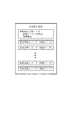
図46は実施の形態3による更新指示情報記憶装置11に格納されている更新指示情報の構造を示す。図25に示す更新指示情報とは異なり、図46の更新指示情報は、地図情報処理装置a1において、更新情報ヘッダで指定された種類および版のデータフレームによって旧版の同種のデータフレームを置換(上書き)するためのものである。実施の形態1と同様に、更新指示情報ヘッダは、管理情報フレーム、表示系データフレーム、経路計算系データフレーム等の更新すべきデータフレームの種類区分(図4参照)を指定する更新データ区分指定と、更新するデータフレームの該当領域を示す領域指定(地域指定)を有する。各更新操作レコードは、更新されたデータフレームそのものを内包するか、更新されたデータフレームそのものを分割したデータ部分を内包する。更新されたデータフレームまたはデータ部分は圧縮されていてもよい。
【0186】
更新指示情報を受信した地図情報処理装置a1のプロセッサ6は、更新指示情報の更新指示情報ヘッダを分析し、更新情報ヘッダで指定された種類および版のデータフレームを、受信したデータフレームによって置換する。送受されるデータフレームが分割または圧縮されている場合は、更新操作レコードの内容から更新されたデータフレームを復元して、更新情報ヘッダで指定された種類および版のデータフレームを、復元したデータフレームによって置換する。
【0187】
実施の形態3においても、表示系データフレームのための更新指示情報および経路計算系データフレームのための更新指示情報は、図28に示すように実施の形態1または実施の形態2と同様に、地図情報処理装置a1からの要求に従って、地図情報提供装置a2から地図情報処理装置a1に個別に提供される。
【0188】
但し、ステップST102では、更新指示情報記憶装置11の更新指示情報データベースに格納されている版別情報から、更新指示情報を取得し、ステップST103ではステップST102で取得した更新指示情報を、要求した地図情報処理装置a1へ送信する。例えば、図10(a)の道路データフレームおよび図13の経路計算データフレームを記憶した地図情報記憶装置4を有する地図情報処理装置a1から表示系データフレームおよび経路計算系データフレームの更新指示情報が要求されたとき、図18または図40の道路データフレームを含む表示系データフレーム、および図21の経路計算データフレームを含む経路計算系データフレームを、それぞれ含む更新指示情報を送信する。
【0189】
図47は、実施の形態3による地図情報処理装置a1のプロセッサ6の動作を示すフローチャートである。図47のフローチャートは、図29のフローチャートのステップST204〜207をステップST500,ST501に置換した点で図29のフローチャートと異なる。他の処理は実施の形態1と同様である。以下、実施の形態1と同様に、図10(a)の道路データフレームを含む表示系データフレーム、および図13の経路計算データフレームを含む経路計算系データフレームを地図情報処理装置a1が保持し、図18の道路データフレームを含む表示系データフレーム、および図21の経路計算データフレームを含む経路計算系データフレームを地図情報提供装置a2が保持すると想定して、地図情報処理装置の動作を説明する。
【0190】
ステップST203では、図18の道路データフレームを含む表示系データフレームおよび図21の経路計算データフレームを含む経路計算系データフレームを内包する更新指示情報をプロセッサ6は送受信装置3により受信する。送受信装置3で受信した更新指示情報をプロセッサ6は、更新指示情報記憶装置5の更新指示情報格納部に格納する。従って、代替リンクを設ける地図情報の更新において、図19のリンク列レコードMR0’のノードリンクレコードNLR03’,NLR04Iのように、元リンクのリンク識別情報と代替リンクに付与された副リンク識別情報とを有する代替リンクのノードリンクレコードを示すデータフレームを取得することができる。
【0191】
上記の更新指示情報の受信において、更新指示情報を取得できた場合は、プロセッサ6は、その更新指示情報を更新指示情報記憶装置5内の更新指示情報格納部(図30参照)に格納すると共にその格納位置、データサイズ、取得状態を取得済みを示すように設定した更新指示情報管理レコードを更新指示情報管理データに格納する。他方、通信障害等により更新指示情報を取得できなかった場合は、プロセッサ6は、要求した更新指示情報の更新指示情報ヘッダに相当するデータを更新指示情報として更新指示情報格納部に格納すると共にその格納位置、データサイズ、取得状態を未取得を示すように設定した更新指示情報管理レコードを更新指示情報管理データに格納する。
【0192】
ステップST500では、プロセッサ6は表示系データフレームを取り出す(読み出す)。具体的には、まずプロセッサ6は、更新指示情報記憶装置5内の更新指示情報格納部より所要の領域(地域)の表示系データフレームの更新指示情報に関する更新指示情報管理レコード内の取得状態をチェックする。ステップST202で決定した領域の表示系データフレームの更新指示情報に関する取得状態が取得済みを示していれば、その更新指示情報に内包された更新済みの表示系データフレームをプロセッサ6は、更新指示情報記憶装置5の更新指示情報格納部から取り出し、更新指示情報記憶装置5の地図情報格納部(図31)へ格納する。他方、更新指示情報管理レコード内の取得状態が未取得を示していれば、プロセッサ6は地図情報記憶装置4からステップST202で決定した領域の表示系データフレームを取り出し、更新指示情報記憶装置5の地図情報格納部へ格納する。従って、表示系データフレームの更新指示情報を受信した地図情報処理装置a1は、更新指示情報に従って表示系データフレームを更新できる。
【0193】
ステップST501では、プロセッサ6は経路計算系データフレームを取り出す(読み出す)。具体的には、まずプロセッサ6は、更新指示情報記憶装置5内の更新指示情報格納部より所要の領域(地域)の経路計算系データフレームの更新指示情報に関する更新指示情報管理レコード内の取得状態をチェックする。ステップST202で決定した領域の経路計算系データフレームの更新指示情報に関する取得状態が取得済みを示していれば、その更新指示情報に内包された更新済みの経路計算系データフレームをプロセッサ6は、更新指示情報記憶装置5の更新指示情報格納部から取り出し、更新指示情報記憶装置5の地図情報格納部(図31)へ格納する。他方、更新指示情報管理レコード内の取得状態が未取得を示していれば、プロセッサ6は地図情報記憶装置4からステップST202で決定した領域の経路計算系データフレームを取り出し、更新指示情報記憶装置5の地図情報格納部へ格納する。従って、経路計算系データフレームの更新指示情報を受信した地図情報処理装置a1は、更新指示情報に従って経路計算系データフレームを更新できる。
【0194】
この実施の形態3によれば、上記動作により、地図情報処理装置a1が自動的に、しかも更新対象位置等の判断を行わずに簡単に地図情報を更新することができる。また、実施の形態1または実施の形態2の地図情報のデータ構造を採用したことにより、地図情報処理装置a1において、版が異なる道路データフレームと経路計算系データが混在しても、代替リンクを含む経路を正しく表示することができる。
【0195】
実施の形態4.
次に、この発明の実施の形態4を説明する。実施の形態4は、上記の実施の形態または実施の形態2のいずれにも応用できる修正であって、ここでは地図情報処理装置a1自身が道路の新設を検出し、その新設道路に基づいて地図情報処理装置a1に更新処理を行わせるための更新指示情報を作成する。図1から図3に示された地図情報処理装置a1および地図情報提供装置a2は実施の形態4でも使用され、実施の形態4における地図情報処理装置a1および地図情報提供装置a2の各構成要素の機能は、実施の形態1または実施の形態2における機能と基本的に同様である。また、地図情報処理装置a1で使用する地図情報(図4)の内容も、実施の形態1または実施の形態2における地図情報の内容と基本的に同様である。また、表示系データフレームのための更新指示情報および経路計算系データフレームのための更新指示情報は、図28に示すように実施の形態1または実施の形態2と同様に、地図情報処理装置a1からの要求に従って、地図情報提供装置a2から地図情報処理装置a1に個別に提供される。
【0196】
但し、この実施の形態4では、地図情報処理装置a1の更新指示情報記憶装置5に車両すなわち地図情報処理装置a1が走行した位置の時間推移を示す走行軌跡情報を格納する走行軌跡格納部と、更新指示情報一時格納部を設けた。これらの走行軌跡格納部と更新指示情報一時格納部に加えて、更新指示情報格納部と地図情報格納部が更新指示情報記憶装置5に設けられているのは上記の通りである。
【0197】
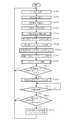
図48は、実施の形態4による地図情報処理装置a1のプロセッサ6の動作を示すフローチャートである。図48のフローチャートは、図29のフローチャートにステップST600,ST617〜ST621を付加した点で図29のフローチャートと異なる。ステップST203で更新指示情報を受信して更新指示情報記憶装置5に格納した後、動作はステップST600の内部更新指示情報取得サブルーティンに移行する。
【0198】
図49は内部更新指示情報取得サブルーティンの詳細な動作を示すフローチャートである。ステップST610では、ステップST201で取得した当該車両の現在位置を更新指示情報記憶装置5の走行軌跡格納部へ格納する。
【0199】
ステップST611では、プロセッサ6は新設道路を検出したか否かを判断する。具体的には、更新指示情報記憶装置5の走行軌跡格納部が示す当該車両の走行軌跡と地図情報記憶装置4に格納された道路データフレームに格納されている各リンクの補間点情報とを比較し、走行軌跡の示す道路形状が道路データフレームに格納されているリンクの補間点情報が示す道路形状のいずれとも一致しない場合、新設道路を検出したことになる。より具体的には、道路データフレームに格納されているリンク上のある位置から発し、他のリンク上のある位置に到達したとき新設道路を検出したとして、動作はステップST612へ進み、そうでないときは内部更新指示情報取得サブルーティンを終了する。例えば、当該車両が図8のリンクLd3の中間位置からリンクLd8の中間位置へ達したとき、図15の道路6を新設道路として検出する。
【0200】
ステップST613では、ステップST612で検出した新設道路を道路データフレーム、経路計算データフレームに追加するための更新指示情報を生成し、生成された道路データフレームのための更新指示情報を更新指示情報記憶装置5の更新指示情報格納部に格納し、生成された経路計算データフレームのための更新指示情報を更新指示情報記憶装置5の更新指示情報一時格納部に一時的に格納する。このとき生成される更新指示情報のデータ構造は地図情報提供装置から送信された更新指示情報のデータ構造と同様である。例えば、上記のように図15の道路6を新設道路として検出した場合は、プロセッサ6は、図8の道路網を図39の道路網に更新するための図44に示すものと同様の更新指示情報を生成し、更新指示情報記憶装置5の更新指示情報格納部に格納する。また、図9の道路網を図17の道路網に更新するための図27に示すものと同様の更新指示情報を生成し、更新指示情報記憶装置5の更新指示情報一時格納部に一時的に格納する。
【0201】
さらにステップST613では、新たな新設道路の検出に備えるため、更新指示情報記憶装置5の走行軌跡格納部に格納された走行軌跡を消去し、この後内部更新指示情報取得サブルーティンを終了する。
【0202】
ステップST600の内部更新指示情報取得サブルーティンを終了した後、プロセッサ6は、地図情報記憶装置4から読み出した表示系データフレームを更新指示情報記憶装置5の更新指示情報格納部に格納された道路データフレーム(表示系データフレーム)のための更新指示情報に従って更新し、更新された表示系データフレームを更新指示情報記憶装置5の地図情報格納部に格納する(ステップST204,ST205)。従って、内部更新指示情報取得サブルーティンにて新設道路が検出されていれば、地図情報処理装置a1自身で生成された更新指示情報に基づいて表示系データフレームは更新される。そうでなければ、地図情報提供装置a2から提供された更新指示情報に基づいて表示系データフレームは更新される。
【0203】
また、ステップST206,ST207でプロセッサ6は、地図情報記憶装置4から読み出した経路計算系データフレームを更新指示情報記憶装置5の更新指示情報格納部に格納された経路計算系データフレームのための更新指示情報に従って更新し、更新された経路計算系データフレームを更新指示情報記憶装置5の地図情報格納部に格納する。従って、内部更新指示情報取得サブルーティンにて新設道路が検出されていてもいなくても、地図情報提供装置a2から提供された更新指示情報に基づいて経路計算系データフレームは更新される。
【0204】
そして、ステップST208のナビゲーション処理サブルーティンで、出力装置7の表示画面の地図表示上に経路表示を行う。内部更新指示情報取得サブルーティンにて新設道路が検出されていれば、地図表示は地図情報処理装置a1自身で検出した新設道路を示す。その場合に、経路計算系データフレームは、地図情報処理装置a1自身の検出を反映していないが、表示系データフレームと経路計算系データフレームの版が異なっていても地図表示および経路表示が可能であることは上述した通りである。
【0205】
この地図表示を当該地図情報処理装置a1の操作者は視て、新設道路と自分の記憶にある当該車両の走行軌跡と比較することができる。ステップST208のナビゲーション処理終了後、更新指示情報記憶装置5の更新指示情報一時格納部に内部取得した経路計算データフレームが残っている場合には(ステップST617)、ステップST618でプロセッサ6は表示された新設道路が正しいか否かを出力装置7を用いて操作者に尋ね、さらにステップST619で操作者が新設道路を確認するための一定期間待機する。操作者はその間、入力装置1に回答を入力することができる。新設道路が正しいことを操作者が回答した場合にのみ、入力装置1は経路計算データフレームの更新を行う旨の指示をプロセッサ6に供給する。
【0206】
次に、ステップST620では、入力装置1により当該地図情報処理装置a1の操作者による経路計算データフレームの更新を行うか否かの指示がされたか否かをプロセッサ6が判断する。経路計算データフレームの更新を行う場合には、動作はステップST621に進み、行わない場合はステップST200へ戻る。
【0207】
ステップST621では、内部取得した経路計算データフレームを更新する。具体的には、更新指示情報記憶装置5の更新指示情報一時格納部に一時的に格納した経路計算データフレームのための更新指示情報を更新指示情報記憶装置5の更新指示情報格納部に格納する。これにより、新設道路に起因して地図情報処理装置a1自身で生成された更新指示情報に基づいて経路計算系データフレームは更新され、更新指示情報格納部に同じ版の表示系データフレームと経路計算系フレームが格納される。
【0208】
上記のように実施の形態4では、地図情報提供装置a2によらず地図情報処理装置a1のみで更新指示情報を生成し、道路データフレームおよび経路計算データフレームを更新することができる。また、実施の形態1または実施の形態2と同様の地図情報のデータ構造を採用することにより、地図情報処理装置a1で生成した更新指示情報に基づいて、道路データフレームのみを更新した場合でも、代替リンクを含む経路を正しく表示することができる。さらに実施の形態1または実施の形態2の更新指示情報のデータ構造を採用することにより、地図情報処理装置a1は更新操作レコードの指定に従って自動的に該当レコードを更新できる。
【0209】
尚、この実施の形態でも、実施の形態2と同じ地図情報のデータ構造を採用すれば、上述のように、対応道路が変更されていない他のリンク列のリンク列レコードでも、交差情報中のノードリンク番号を変更する必要がないので、更新すべき情報量が少なくて済み、情報処理能力が低い地図情報処理装置a1でも更新指示情報を作成することができる。また、情報処理能力が低い地図情報処理装置a1では、更新処理の増大を来たさず、より短い時間で道路データフレームの更新ができる。
【0210】
尚、実施の形態1〜4に関連する説明では、一つの元リンクを二つの代替リンクで置換する場合を示したが、三つ以上の代替リンクで一つの元リンクを置換してもよい。
【0211】
また、実施の形態1〜4に関連する説明では、代替リンク列で表される道路形状が元リンクで表される道路形状に一致する場合を示したが、代替リンクの道路形状が元リンクの道路形状に一致しなくてもよい。例えば、実世界では、道路が新設されるときに、新設された道路に交差する道路部分の形状が変更される場合がある。このような場合には、代替リンクの両端または一端のノードの座標や補間点の座標が変更されるが、座標の情報を書き換える指示を含む更新指示情報により、地図情報処理装置a1は地図情報を更新できる。
【0212】
また、実施の形態1〜4では、現在位置情報を取得するたびに、地図情報処理装置a1が更新指示情報要求を地図情報提供装置a2に送信するが、この発明をこの実施の形態に限定するものではなく、更新指示情報要求の送信タイミングは用途に応じて任意に選択してもよい。例えば、事前に地図情報処理装置a1が地図情報提供装置a2に更新されたデータがあるか否かを問い合わせて、更新の必要性がある場合にのみ地図情報処理装置a1が更新指示情報要求を地図情報提供装置a2に送信するようにしてもよい。
さらに、実施の形態1〜4では、地図情報処理装置a1は更新された地図情報を更新指示情報記憶装置5に格納するが、更新された地図情報を地図情報記憶装置4に格納(すなわち上書き保存)してもよい。
【0213】
また、実施の形態1〜4においては、地図情報提供装置a2から更新指示情報を取得するために通信手段を用いたが、更新指示情報の配信は通信に限定されず、例えばメモリカードまたはディスクのようなリムーバブルな記憶媒体を用いてもよい。
【0214】
また、上述の実施の形態での地図情報処理装置a1は、自動車に搭載されたカーナビゲーション装置であるが、この発明を実施の形態に限定する意図ではなく、地図情報処理装置a1は、携帯電話、携帯情報端末等の移動体に設けられていてもよい。あるいは、地図情報処理装置a1は固定されたコンピュータ端末でもよい。これらの代替的な形態では、位置検出装置2は、地図情報処理装置a1が移動体である場合に設けられるが、固定された端末である場合には必要ではない。
【0215】
また、この発明に係るデータ構造は、上述と異なる形式の地図情報に採用してもよい。例えば、主要道路だけを記述した地図表示用データフレームと、主要道路に加えて二次的な道路を記述した縮尺が異なる地図表示用データフレームが階層化された地図情報に採用できる。この地図情報では、このような用途が異なる地図表示用データフレームの一つが更新され他が更新されない場合に、更新された地図表示用データフレームによれば新たな主要道路が表示されるのに、旧版の地図表示用データフレームによればその主要道路が表示されないという事態が発生するおそれがある。しかし、この発明によって元リンクと代替リンクの関連付けを行うことで、新版と旧版の相違による表示の不統一をなくすことが可能である。
【0216】
【発明の効果】
以上のように、この発明によれば、地図情報のデータ構造は、現実の道路部分にそれぞれ対応する個々の元リンクを表すリンク識別情報と、いずれかの元リンクを置換するように設けられる二以上の代替リンクを表すために使用される副リンク識別情報とを備えており、各リンクについてリンク識別情報と副リンク識別情報が対応付けられて、地図情報処理装置によって元リンクと代替リンクの関連付けが可能にされている。従って、更新されたデータと更新に失敗したデータが混在しても、地図情報処理装置では代替リンクと元リンクの対応づけが可能であるので、適切な処理を実現できる。
【0217】
この発明によれば、地図情報のデータ構造は、現実の道路網の道路部分に対応する個々のリンクをそれぞれ表現する複数のノードリンク情報を備えており、各ノードリンク情報が、現実の道路部分に対応するリンクを表すリンク識別情報と、元リンクを置換する二以上の代替リンクが設けられる場合に元リンクが無効であることを示す無効リンク情報と、上記代替リンクからなるリンク列と上記元リンクとを対応付ける接続情報とを有することによって、地図情報処理装置によって元リンクと代替リンクの関連付けが可能にされている。従って、更新されたデータと更新に失敗したデータが混在しても、地図情報処理装置では代替リンクと元リンクの対応づけが可能であるので、適切な処理を実現できる
【図面の簡単な説明】
【図1】 この発明の実施の形態1〜4に係る地図情報更新システムを示すブロック図である。
【図2】 この発明の実施の形態1〜4に係る地図情報処理装置のブロック図である。
【図3】 この発明の実施の形態1〜4に係る地図情報提供装置のブロック図である。
【図4】 この発明の実施の形態1〜4に係る地図情報の概略データ構造を示す図である。
【図5】 変更前の実際の道路網を示す地図である。
【図6】 この発明に係る地図情報の道路データフレームの作成のために仮想的にノード、リンクが割り振られた道路網を示す図である。
【図7】 この発明に係る地図情報の経路計算系データフレームの作成のために仮想的にノード、リンクが経路計算に使用する重要な道路に割り振られた道路網を示す図である。
【図8】 図6の道路網を構成する道路をリンク列に分解し、各リンクに識別のためにリンク識別番号を付与した道路網を示す図である。
【図9】 図7の経路計算に使用するリンクと、図8に示されたリンク識別番号との関係を示す図である。
【図10】 (a)は図4の地図情報の表示系データフレームにおける更新前の道路データフレームの構造を示す図である。(b)は(a)の道路データフレーム中のリンク列レコードのデータ構造を示す図である。
【図11】 図10(a)における道路データフレーム中のリンク列レコードのノードリンクレコードの詳細を示す図である。
【図12】 図10(a)における道路データフレーム中の他のリンク列レコードのノードリンクレコードの詳細を示す図である。
【図13】 図4の地図情報の経路計算系データフレームにおける更新前の経路計算データフレームの構造を示す図である。
【図14】 図13の経路計算データフレーム中のノードレコードの詳細を示す図である。
【図15】 変更後の実際の道路網を示す地図である。
【図16】 この発明の実施の形態1に係る地図情報の道路データフレームの更新のために、図15の道路網を構成する道路をリンク列に分解し、各リンクにリンク識別番号を付与した道路網を示す図である。
【図17】 この発明の実施の形態1〜4に係る地図情報の経路計算系データフレームの更新のために仮想的にノード、リンクが経路計算に使用する重要な道路に割り振られた道路網を示す図である。
【図18】 実施の形態1に係る更新後の道路データフレームの構造を示す図である。
【図19】 図18における道路データフレーム中のリンク列レコードのノードリンクレコードの詳細を示す図である。
【図20】 図18における道路データフレーム中の他のリンク列レコードのノードリンクレコードの詳細を示す図である。
【図21】 実施の形態1〜4に係る更新後の経路計算データフレームの構造を示す図である。
【図22】 図21の経路計算データフレーム中のノードレコードの詳細を示す図である。
【図23】 図21の経路計算データフレーム中の他のノードレコードの詳細を示す図である。
【図24】 この発明に係る地図情報提供装置に格納された更新指示情報データベースの構造を示す図である。
【図25】 この発明の実施の形態1,2に係る更新指示情報のデータ構造の例を示す図である。
【図26】 (a)は道路データフレームの更新のための更新操作レコードを含む更新指示情報を示す図である。(b)は道路データフレームの更新のための更新操作レコードの詳細を示す図である。
【図27】 (a)は経路計算データフレームの更新のための更新操作レコードを含む更新指示情報を示す図である。(b)は経路計算データフレームの更新のための更新操作レコードの詳細を示す図である。
【図28】 この発明の実施の形態1〜4による地図情報提供装置の動作を示すフローチャートである。
【図29】 この発明の実施の形態1,2による地図情報処理装置の動作を示すフローチャートである。
【図30】 この発明の実施の形態1〜4による地図情報処理装置の更新指示情報記憶装置の更新指示情報格納部の構成を示す図である。
【図31】 この発明の実施の形態1〜4による地図情報処理装置の更新指示情報記憶装置の地図情報格納部の構成を示す図である。
【図32】 この発明の実施の形態1による地図情報処理装置のナビゲーション処理の動作を示すフローチャートである。
【図33】 (a)は旧版の表示系データフレームに基づく地図表示画面を示す図である。(b)は新版の表示系データフレームに基づく地図表示画面を示す図である。
【図34】 ナビゲーション処理において地図情報処理装置で作成される経路情報の構造を示す図である。
【図35】 更新された経路計算データフレームに基づいて作成された経路情報の内容の具体例を示す図である。
【図36】 未更新の経路計算データフレームに基づいて作成された経路情報の内容の具体例を示す図である。
【図37】 (a)は未更新の道路データフレームに基づく道路表示に、好適経路が重ねて表示された地図表示画面を示す図である。(b)は更新された道路データフレームに基づく道路表示に、好適経路が重ねて表示された地図表示画面を示す図である。
【図38】 この発明の実施の形態2に係る更新前の道路データフレーム中のリンク列レコードのノードリンクレコードの詳細を示す図である。
【図39】 この発明の実施の形態2に係る地図情報の道路データフレームの更新のために、変更後の道路網を構成する道路をリンク列に分解し、各リンクにリンク識別番号を付与した道路網を示す図である。
【図40】 図39の道路網を表す実施の形態2に係る更新後の道路データフレームの構造を示す図である。
【図41】 図40における道路データフレーム中のリンク列レコードのノードリンクレコードの詳細を示す図である。
【図42】 図40における道路データフレーム中の他のリンク列レコードのノードリンクレコードの詳細を示す図である。
【図43】 図40における道路データフレーム中の他のリンク列レコードのノードリンクレコードの詳細を示す図である。
【図44】 この発明の実施の形態2に係る更新指示情報のデータ構造の例を示す図である。
【図45】 この発明の実施の形態2による地図情報提供装置の動作を示すフローチャートである。
【図46】 この発明の実施の形態3に係る更新指示情報のデータ構造を示す図である。
【図47】 この発明の実施の形態3による地図情報処理装置の動作を示すフローチャートである。
【図48】 この発明の実施の形態4による地図情報処理装置のナビゲーション処理の動作を示すフローチャートである。
【図49】 この発明の実施の形態4による地図情報処理装置の内部更新指示情報取得処理の動作を示すフローチャートである。
【符号の説明】
1 入力装置、2 位置検出装置、3 送受信装置(受信部)、4 地図情報記憶装置、5 更新指示情報記憶装置(格納部)、6 プロセッサ(更新処理部)、7 出力装置、10 送受信装置(送信部)、11 更新指示情報記憶装置(更新指示情報記憶部)、12 更新指示情報配信装置。[0001]
BACKGROUND OF THE INVENTION
The present invention relates to map information used in a mobile object such as a car navigation device, a mobile phone, a portable information terminal, or a fixed computer terminal.Land ofThe present invention relates to an information processing apparatus and a map information providing apparatus.
[0002]
[Prior art]
In the car navigation device, a route calculation (route search) from the departure point to the destination is performed, and suitable route candidates obtained as a result are presented on the screen of the display device together with the road map. A function similar to this is also performed in other mobile objects such as a mobile phone and a portable information terminal, or a fixed computer terminal.
As a data structure of map information used in such a route search device, there is one having a set of data for road map display and a set of data for route calculation in order to increase the processing speed. For example,
[0003]
[Patent Document 1]
JP-A-8-292716
[0004]
[Problems to be solved by the invention]
Regarding the data structure of the above conventional map information, the data for road map display and the data for route calculation are mutually coordinated when the data is updated due to the establishment or abolition of roads, the satisfaction of map information, etc. Therefore, it is considered that both the updated road map display data and the route calculation data need to be stored in each user's device. As a method of updating data by each user's device, a method of distributing a recording medium storing the updated data and a method of distributing the updated data itself by communication are conceivable. In either case, only one of the data may be updated by the user's device, and the data may not match each other. That is, even when a recording medium is distributed, the update of one data may fail due to a malfunction of the apparatus. When distributing data by communication, the data for route calculation is updated to the latest state. However, there is a case where it is not possible to obtain update instruction information for road map display data due to a communication failure. If different versions of data are stored in the user's device in this way, there is a possibility that the desired route cannot be displayed correctly on the screen of the display device even if the route is calculated.
[0005]
The present invention has been made to solve the above-described problem, and even if updated data and data that has failed to update are mixed, appropriate processing can be realized.LandAn object is to obtain a figure information processing apparatus and a map information providing apparatus.
[0006]
[Means for Solving the Problems]
The map information processing apparatus according to the present invention has map information storage means for storing map information having data representing a road network by links provided corresponding to roads, and link identification information is included in the link of the map information. Is granted,In the update that replaces the original link that is one of the links in the map information with two or more alternative links, the link identification information of the original link and the sub-link identification information that represents the alternative link itself are given to the alternative link , Replace the original link with an alternative linkIt has an update means.
[0007]
According to this inventionIn the map information providing apparatus, the update operation information for replacing the original link with the substitute link includes link identification information representing the original link and sub-link identification information representing the substitute link itself, and the update operation information is An update instruction information storage unit to be stored and a transmission unit that transmits the update operation information to the map information processing apparatus are provided.
[0008]
DETAILED DESCRIPTION OF THE INVENTION
Hereinafter, various embodiments according to the present invention will be described with reference to the drawings.
FIG. 1 is a block diagram showing a configuration of a map information update system according to
[0009]
FIG. 2 is a block diagram showing details of the map information processing apparatus a1 shown in FIG. As shown in FIG. 2, the map information processing apparatus a1 includes an
[0010]
The
[0011]
The map
[0012]
The
[0013]
Furthermore, the
[0014]
The
[0015]
FIG. 3 is a block diagram showing a configuration of the map information providing apparatus a2 shown in FIG. The map information providing device a2 includes a transmission / reception device (transmission unit) 10, an update instruction information storage device (update instruction information storage unit) 11, and an update instruction
[0016]
FIG. 4 shows a schematic data structure of map information stored in the map
[0017]
Each display system data frame corresponds to one region (region), and has various data for causing the display device of the
[0018]
The guidance search data frame has, for example, destination data (address, building telephone number, etc.) and information indicating the relationship between the destination and the area, and the necessary area according to the destination specified by the user. Are used to select the display system data frame and the route calculation system data frame.
[0019]
The management information frame is data used for management and reading of a display data frame, a route calculation data frame, a guidance search data frame, etc., for example, the location of each data frame in map information, the version of each data frame Have data to show.
[0020]
As shown in FIG. 4, each display system data frame is a map of road data frames, rivers, seas, etc. used for map matching (specification of the road based on the current position and identification of the position on the road) and road display. It has a background data frame for displaying a background, a name data frame for displaying names such as place names in characters, a route guidance data frame for route guidance, a peripheral facility data frame for searching surrounding facilities, and the like. Each display system data frame has a display system data header. The display system data header includes various attributes related to the display system data frame including information indicating the area to which the display system data frame corresponds, and the display system data frame. Information for managing the location of each data frame included in the data frame is included.
[0021]
The route calculation data frame has a route calculation data frame for route calculation and a route calculation data header. The route calculation system data header manages various attributes related to the route calculation system data frame including information indicating the area corresponding to the route calculation system data frame, and the location of each route calculation data frame included in the route calculation system data frame. It has information to do.
[0022]
Before describing the update of map information according to this embodiment, the data structure of map information, details of data elements, and the basic principle of creating map information will be described. FIG. 5 is a map showing an actual road network provided in a certain area. In the example of FIG. 5, a plurality of
[0023]
FIG. 6 shows the connection relationship between the
[0024]
As shown in FIG. 6, when creating a display data frame, one road is handled as a link string. That is, road 0 (FIG. 5) is called
[0025]
FIG. 7 shows nodes and links virtually allocated to a road network composed of
[0026]
FIG. 8 shows link
[0027]
As shown in FIG. 8, road intersections can be represented as link row intersections or connections. For example, the intersection of
[0028]
FIG. 9 shows the relationship between the route calculation system links Lr0 to Lr4 in FIG. 7 and the link identification numbers shown in FIG. A head link identification number and a termination link identification number are assigned to each of the route calculation system links Lr0 to Lr4 in FIG. That is, one link (for example, link Lr1) in FIG. 7 is assigned with the minimum link identification number (for example, 102) assigned to the corresponding link (for example, links Ld2 to Ld4) in FIG. 8 as the first link identification number. The maximum link identification number (for example, 104) is given as the termination link identification number. Since each link identification number is given in ascending order and sequentially in the forward direction of the link string, the display system link of FIG. 8 corresponding to the route calculation system link of FIG. 7 has its head link identification number and terminal link identification number. Can be specified. For example, for the link Lr1 in FIG. 7, the links Ld2, Ld3, and Ld4 having the
[0029]
FIG. 10A shows an example of a road data frame in the display system data frame of FIG. The road data frame has a road data header and a plurality of link row records. The road data frame in FIG. 10A represents the road network in FIG. The link string records MR0 to MR5 in the figure are provided so as to correspond to the link strings 0 to 5 in FIG. 8, respectively, and store information related to the corresponding link string (road). The arrangement order of the link string records is called a link string number, and the link string records MR0 to MR5 can be specified using the
[0030]
The link string records MR0 to MR5 in FIG. 10A will be described by taking the link string record MR0 (corresponding to the link string 0) as an example. FIG. 10B shows the data structure of the link string record MR0 of FIG. The link string record has a link string header and a plurality of node link records. The node link records NLR00, NLR01, NLR02, NLR03, NLR04, and NLR05 in FIG. 10B are node and link pairs (Nd0, Ld0) and (Nd1, Ld1) that appear when the
[0031]
The node link record stores information about the corresponding node and link. For example, the node link record NLR00 stores information regarding the node Nd0 and the link Ld0 (link identification number 100). The link row header stores the data size of the link row record, the road type of the road (for example,
[0032]
FIG. 11 shows the node link records NLR00 to NLR05 of the link string record MR0 (corresponding to the link string 0) and the node link records NLR50 and NLR51 of the link string record MR5 (corresponding to the link string 5) in FIG. . Each node link record has a node link header, intersection information, node coordinates, link identification information, sub-link identification information, and interpolation point information.
[0033]
The node link header stores the number of interpolation points of the corresponding link, and sub link identification presence / absence information indicating whether or not a corresponding link is assigned a sub link identification number. Although not shown, the data size of the node link record, link attributes such as the road width of the corresponding link, and the like are also stored. The secondary link identification number is used in the updated road data frame to change the road network, such as the construction of new roads, or to satisfy map information in line with actual roads. This is related to data updates. Further details will be described later. In the example of FIG. 11, since the sub-link identification number is not assigned to the road network of FIG. 8 before the change, the sub-link identification presence / absence information stores a value indicating “none”.
[0034]
The intersection information stores a link string number indicating a link string of a connection destination and a node link number of a node link record corresponding to a node of the link string of the connection destination. For example, the intersection information of the node link record NLR04 (corresponding to the node Nd4 and the link Ld4 in FIG. 8) of the link row record MR0 is the
[0035]
The node coordinate stores a coordinate value indicating the geographical position of the corresponding node. The link identification information stores the link identification number assigned to the corresponding link. For example, in the node link record NLR00, the
[0036]
The secondary link identification information is used in the updated road data frame for changing the road network, such as the construction of new roads, or for the fulfillment of map information in accordance with the actual road, and the secondary link identification number is assigned to the corresponding link. Exists only when the sublink identification number is assigned, and the sublink identification number of the corresponding link is stored in the sublink identification information. In the example of FIG. 11, the sub-link identification number information is not provided because the sub-link identification number is not given to the road network before the change in FIG.
The interpolation point information exists only when the corresponding link has one or more interpolation points, and the interpolation point information stores coordinate values indicating the geographical position of each interpolation point of the link. For example, in the node link record NLR04 (corresponding to the node Nd4 and the link Ld4 in FIG. 8) of the link row record MR0, the coordinates of the interpolation point P4 on the link Ld4 are stored in the interpolation point information.
[0037]
FIG. 12 similarly shows the node link records NLR10 to NLR15 of the link string record MR1 (corresponding to the link string 1) and the node link records NLR30 and NLR31 of the link string record MR3 (corresponding to the link string 3) in FIG. The data structure and stored contents of are shown. A display data frame used for map matching or road display has the above-described structure.
[0038]
FIG. 13 shows an example of a route calculation data frame in the route calculation system data frame of FIG. The route calculation data frame has a route calculation data header and a node record. It is assumed that the route calculation data frame of FIG. 13 represents the road network of FIG. The node records NrR0 to NrR5 in the figure are provided so as to correspond to the nodes Nr0 to Nr5 in FIG. 7, respectively. Information for managing node records such as the number of node records is stored in the route calculation data header. The node record stores information about the corresponding node. The order in which node records are arranged is called a node number.
[0039]
The node record in FIG. 13 will be described by taking the node record NrR1 (corresponding to the node Nr1) as an example. FIG. 14 shows the data structure of the node record NrR1 of FIG. The node record has a node record header and one or more connection records. The connection records CR10, CR11, and CR12 in FIG. 14 correspond to the links Lr1, Lr4, and Lr0 connected to the node Nr1 corresponding to the node record NrR1, respectively.
[0040]
The node record header stores the data size of the node record, the coordinate value indicating the geographical position of the node Nr1 corresponding to the node record, the number of connection records of the node record, and the like.
[0041]
Each connection record has a connection record header, an adjacent node number, a link cost, corresponding link identification information, corresponding sub-link identification information, and traffic regulation information.
The connection record header stores data size of the connection record and corresponding sub link identification presence / absence information indicating the presence / absence of corresponding sub link identification information. Corresponding sub-link identification information is used in the updated route calculation data frame for changing the road network such as the establishment of a new road or for satisfying map information in line with the actual road. Further details will be described later. In the example of FIG. 14, since the sub-link identification number is not given to the road network before the change in FIG. 8, the sub-link identification presence / absence information stores a value indicating “none”.
[0042]
In the adjacent node number, the node number of the node (any of nodes Nr2, Nr4, Nr0) adjacent to the node on the link (any of links Lr1, Lr4, Lr0) connected to the node (node Nr1) Is stored. For example, in the connection record CR10, the
[0043]
The link cost stores the time required for traveling the link corresponding to the connection record (for example, the link Lr1 in the connection record CR10) as an index for cost evaluation in route calculation.
[0044]
The corresponding link identification information stores the first link identification number and the end link identification number (see FIG. 8) of the link corresponding to the connection record.
[0045]
Corresponding link sub-identification information is used in the updated route calculation data frame for changing the road network, such as the establishment of a new road, or for the fulfillment of map information in line with the actual road, and corresponds to the connection record. The head sublink identification number and the terminal sublink identification number of the link to be stored are stored. However, in the example of FIG. 14, since the sub-link identification number is not given to the link before the change of FIG. 8, no corresponding link sub-identification information is provided. Corresponding link identification information (corresponding link identification information and corresponding sub link identification information when corresponding sub link identification information is present) is used to display the display links Ld0,. . . The range of (FIG. 8) is shown.
The traffic regulation information stores information indicating the traffic regulation related to the link corresponding to the connection record.
The route calculation system data frame used for route calculation has the above structure. The map information having the data structure described above is stored in the map
[0046]
Next, the update of the map information for the satisfaction of the map information according to the change of the road or the actual road will be described. FIG. 15 is a map showing a road network in which one
[0047]
FIG. 16 is a diagram similar to FIG. 8, and in updating the display system data frame, nodes, links, and link strings virtually allocated to indicate the connection relationship of the changed
[0048]
When a certain link is replaced with an alternative link as described above, the original link is replaced with an original link such as links Ld3 and Ld8, and an alternative link such as links Ld3 ′, Ld3 ″, Ld8 ′ and Ld8 ″ is replaced. This is called an alternative link. Further, the link identification number of the original link (for example, the
[0049]
Further, a sub-link identification number that is a link identification number different from the original link identification number is assigned to the alternative link, and the alternative link is identified using the original link identification number and the sub-link identification number. As a sub-link identification number, a
[0050]
In order to indicate which original link the secondary link identification number relates to, the secondary link identification number is combined with the link identification number of the original link. That is, when the link identification number of the original link is set to idx and the sub-link identification number sid is set, the general link identification number idx: sid is assigned to the alternative link. For example, when the link identification number of the original link L is idx, the alternative link L0, L1, ..., LM-1Includes a general link identification number idx: 0 to idx: SID.1-1, idx: SID1~ Idx: SID2-1, ..., idx: SIDM-1~ Idx: SIDMAXIs granted.
[0051]
In this embodiment, the SIDMAX
[0052]
Further, for convenience between the link identification number and the general link identification number, that is, the magnitude relationship in data notation is determined as follows. For example, it is assumed that there are three link identification numbers id1, id2, and id3, and two total link identification numbers related to the link identification numbers id2 and id3 are id2: sid2, id3: sid3. The magnitude relationship in data notation between the link identification number and the general link identification number is determined as follows.
If id1> id2 id1> id2: sid2,
If id1 = id2 id1 = id2: sid2,
If id1 <id2, id1 <id2: sid2.
[0053]
The magnitude relationship in data notation between the general link identification numbers is determined as follows.
If id2> id3 id2: sid2> id3: sid3,
When id2 = id3
If sid2> id3, then id2: sid2> id3: sid3,
If sid2 = id3, id2: sid2 = id3: sid3.
[0054]
In addition, the magnitude relationship in the data notation between the link identification numbers follows the magnitude relationship in the data notation of the link identification number.
[0055]
As will be described later, a range of link identification numbers occupied by a plurality of serial display links can be represented in accordance with the above-described magnitude relationship in data notation. This range of link identification numbers is used for updating the route calculation system data frame.
[0056]
FIG. 17 is a diagram similar to FIG. 7, and the nodes virtually allocated to the road network composed of the
[0057]
The route calculation system link Lr1 ′ corresponds to the display system links Ld2 and Ld3 ′ in FIG. 16, the link Lr1 ″ corresponds to the links Ld3 ″ and Ld4 in FIG. 16, and the link Lr3 ′ corresponds to the links Ld7 and Ld8 ′ in FIG. Correspondingly, the link Lr3 ″ corresponds to the links Ld8 ″ and Ld9 in FIG. 16, and the link Lr5 corresponds to the link Ld14 in FIG.
[0058]
The range of link identification numbers occupied by the display system links Ld2 and Ld3 ′ of FIG. 16, that is, the route calculation system link Lr1 ′, is based on the original
[0059]
The link identification number ranges 102 to 103: 127 include original
[0060]
By using the original link identification number and the secondary link identification number as the link identification number of the alternative link as described above, the map information data frame (for example, the old version display system data frame and the new version route calculation system data frame). ) Can be associated with the display system link and the route calculation system link.
[0061]
In the same manner, as shown in FIG. 17, the range of link identification numbers is given to the route calculation system links Lr3 ′ and Lr3 ″ based on the original link identification number and the total link identification number. The pair of the start link identification number / end link identification number is not changed for the route calculation system links Lr0, Lr2, Lr4, and for the newly established Lr5, the start link identification number and the end link identification number are both 114.
[0062]
The road data frame shown in FIG. 18 is an updated road data frame representing the road network of FIG. In the road data frame shown in FIG. 18, link train records MR0 ′, MR1 ′, MR5 ′ correspond to
[0063]
FIG. 19 shows node link records NLR00 to NLR05 of the link string record MR0 ′ (corresponding to link string 0) and node link records NLR50 and NLR51 in the link string record MR5 ′ (corresponding to link string 5) in FIG. The structure of each node link record of the link string record in FIG. 19 is the same as the structure of each node link record of the original link string record shown in FIG. The new link sequence record MR0 ′ in FIG. 19 has a new node link record NLR03 ′ in which the new node link record NLR04I is inserted and the old node link record NLR03 is modified with respect to the original link sequence record MR0 in FIG. It is different in point.
[0064]
The newly added node link record NLR04I corresponds to the newly established node Nd12 shown in FIG. 16 and the link Ld3 ″ existing in the forward direction. The old node link record NLR03 is a node shown in FIG. In contrast to Nd3 and link Ld3, the modified new node link record NLR03 ′ corresponds to node Nd3 and link Ld3 ′ shown in FIG. 16. The original link Ld3 is divided into new links Ld3 ′ and Ld3 ″. Accordingly, in the new node link record NLR03 ′, the sub link identification presence / absence information is changed to indicate “present”, the number of interpolation points and the interpolation point coordinates are updated, and the sub link identification information is inserted. Also in the added node link record NLR04I, the sub link identification presence / absence information indicates “Yes”, and the sub link identification information is valid.
[0065]
The secondary link identification information of the node link records NLR03 ′ and NLR04I includes the minimum value of the secondary link identification number assigned to the links Ld3 ′ and Ld3 ″ (0 for the link Ld3 ′ and 128 for the link Ld3 ″ as shown in FIG. 16). ). The range of the sub link identification number assigned to each link can be determined from the link identification number and the sub link identification number of the node link record and the next node link record. For example, the node link records NLR03 ′ and NLR04I have the same link identification information (link identification number = 103), and the node link record NLR04I has a node link number of 4 (see FIG. 10B) and the sublink identification information is 128. Therefore, it can be determined that the link Ld3 ′ having the
[0066]
On the other hand, the link string record MR5 '(corresponding to the link string 5) is obtained by changing the node link number of the intersection information of the node link records NLR50 and NLR51 in the original link string record MR5 in FIG. This is because the node link number of the existing node Nd4 (corresponding to the node link record NLR50) changes from 4 to 5 due to the addition of the node Nd12 to the link string 0 (see FIG. 16), and the node Nd13 to the
[0067]
FIG. 20 shows a node link record of the link string record MR1 '(corresponding to link string 1) in FIG. The link string record MR1 'is updated in a format similar to that of the link string record MR0'. That is, the new link sequence record MR1 ′ in FIG. 20 is a new node link record NLR13 ′ in which the new node link record NLR14I is inserted into the original link sequence record MR1 in FIG. 12 and the old node link record NLR13 is modified. It is different in having.
As the contents of these link string records MR0 ', MR1', MR5 'are updated, the link string header (see FIG. 10B) of each link string record is also updated.
[0068]
FIG. 21 shows a route calculation data frame representing the changed road network shown in FIG. 17, and FIG. 22 shows a data structure of one node record of FIG. The structure of the route calculation data frame and the node record in FIGS. 21 and 22 is the same as the structure of the original route calculation data frame and the node record shown in FIGS. In the path calculation data frame in FIG. 21, new node records NrR6, NrR7 are added to the original path calculation data frame in FIG. 13, and new node records NrR1 are modified from the old node records NrR1, NrR2, NrR4, NrR5. ', NrR2', NrR4 ', and NrR5'.
[0069]
The newly added node records NrR6 and NrR7 correspond to the newly established nodes Nr6 and Nr7 shown in FIG. Further, the updated node records NrR1 ′, NrR2 ′, NrR4 ′, NrR5 ′ correspond to the nodes Nr1, Nr2, Nr4, Nr5, respectively, similarly to the old node records NrR1 ′, NrR2 ′, NrR4 ′, NrR5 ′. . Further, the route calculation data header is also updated in accordance with the update of the node record.
[0070]
The node record in FIG. 21 will be described by taking the node record NrR1 ′ (corresponding to the node Nr1) as an example. FIG. 22 shows the data structure of the node record NrR1 'of FIG. The node record NrR1 'in FIG. 22 is obtained by updating the node record header and connection record CR10 of the node record NrR1 in FIG. 14 as follows.
[0071]
First, by adding the
[0072]
Corresponding sub-link identification information having a leading sub-link identification number of 0 and a terminal sub-link identification number of 127 is inserted. The starting sub link identification number is given the minimum value of the range of sub link identification numbers assigned to the alternative link, and the terminal sub link identification number is given the maximum value of the range of sub link identification numbers. The corresponding link identification information and the corresponding secondary link identification information cooperate to link the link Lr1 ′ in series with the link identification number range shown in FIG. 16 in the range of 102 to 103: 127, that is, the links Ld2 and Ld3. 'Indicates that it corresponds. Therefore, the corresponding link in the old version road data frame can be determined based on the new version route calculation data frame.
[0073]
FIG. 23 shows the main contents of the connection record constituting the node record NrR6 as an example of the added node record in the route calculation data frame of FIG. Connection records CR60, CR61, and CR62 in FIG. 23 correspond to the links Lr1 ″, Lr5, and Lr1 ′ connected to the node Nr6 corresponding to the node record NrR6, respectively. The connection record CR60 is linked to the link Lr1 by the adjacent node number. ”Indicates that the adjacent node of the node Nr6 is the node Nr2 (see FIG. 17), and the link Lr1” is the range of the link identification numbers shown in FIG. 16 by the corresponding link identification information and the corresponding sub link identification information. Corresponds to the serial links at 103: 128 to 104, ie, links Ld3 ″ and Ld4. The connection record CR61 indicates that the adjacent node of the node Nr6 via the link Lr5 is the node Nr7 by the adjacent node number, and the link Lr5 is shown in FIG. 16 by the corresponding secondary link identification presence / absence information and the corresponding link identification information. The link identification number range corresponds to 114 links, that is, the link Ld14. The connection record CR62 indicates that the adjacent node of the node Nr6 via the link Lr1 ′ is the node Nr1 by the adjacent node number, and the link Lr1 ′ is shown in FIG. 16 by the corresponding link identification information and the corresponding sublink identification information. It is indicated that the range of the link identification numbers assigned corresponds to the serial links of 102 to 103: 127, that is, the links Ld2 and Ld3 ′.
[0074]
As described above, the updated map information has a data structure in accordance with the basic principle described with reference to FIGS. By using the original link identification number and the secondary link identification number as the link identification number of the alternative link as described above, the map information data frame (for example, the old version display system data frame and the new version route calculation system data frame). ) Can be associated with the display system link and the route calculation system link.
[0075]
Therefore, if the map information processing apparatus a1 can acquire the updated map information, the map information processing apparatus a1 can also perform map display, map matching, and route calculation for the latest actual road. As described above, even if the version of the display data frame and the route calculation data frame are different, the link can be associated. Therefore, the map information processing apparatus a1 can acquire only one data frame. It is also possible to display the route correctly. As a method for the map information processing apparatus a1 to acquire the updated map information, in this embodiment, the map information providing apparatus a2 transmits the update instruction information to the map information processing apparatus a1, and the map information according to the update instruction information. When the processing device a1 changes the original map information, updated map information can be obtained (that is, the map information can also be updated by the individual map information processing device a1).
[0076]
Next, a method for updating the map information by the map information processing apparatus a1 will be described. FIG. 24 shows the structure of the update instruction information database stored in the update instruction information storage device 11 (see FIG. 3) of the map information providing device a2. When the map information provider adds update instruction information (described later) to the update instruction information database, the map information provider performs necessary modifications to other elements (version number management information described later) along with the addition.
[0077]
The update instruction information database has a list of one version number management information and one or more version-specific information. Each version-specific information is information for updating a certain version of map information to the latest version of map information, and there are as many versions as there are existing versions. The version number management information is information for managing these pieces of version information, and indicates the version number, location, data size, etc. of each version information.
[0078]
Each version-specific information includes one update instruction information management information and one or more update instruction information. The update instruction information is provided for the corresponding version of the display system data frame and the path calculation system data frame, and is provided to update each version of the display system data frame and each version of the path calculation system data frame to the latest version. It has been. However, update instruction information may also be provided for the management information frame, the guidance search data frame (see FIG. 4), or other data frames. The update instruction information management information is information for managing these update instruction information, and indicates the location, data size, and the like of each update instruction information.
[0079]
When receiving the update instruction information request from the map information processing apparatus a1, the map information providing apparatus a2 refers to the version number management information and the update instruction information management information in the update instruction information database in the update instruction
[0080]
FIG. 25 shows an example of the data structure of the update instruction information shown in FIG. As shown in FIG. 25, the update instruction information includes a single update instruction information header and an array of one or more update operation records. The update instruction information header indicates the type classification and area (corresponding area) of the data frame to be updated. That is, the update instruction information header includes an update data classification designation that designates a type classification (see FIG. 4) of a data frame to be updated, such as a management information frame, a display data frame, and a route calculation data frame, and a data frame to be updated. It has area designation (area designation) indicating the corresponding area.
[0081]
The update operation record indicates a data operation to be performed for updating the data frame indicated by the update instruction information header. Each update operation record has an update target type, an update operation designation, an update target position, and update data. The update target type designates a display system data header, a road data frame, a route calculation system data header, a route calculation data frame, or the like as the type of data to be updated in the data frame indicated by the update instruction information header. The update operation designation designates the type of update operation such as deletion, addition, insertion and overwriting.
The update target position indicates the position of the update target in the data designated by the update target type. The update data is the content of the data to be added, inserted or overwritten. In the case of deletion, no update data is provided.
[0082]
More specifically, the update target position has a first record number, a second record number, an update target offset, and an update target data size. The first record number is the link string number of the link string record to be updated (see FIG. 10A and FIG. 18), the node number of the node record to be updated (see FIG. 13 and FIG. 21), etc. Indicates. The second record number indicates the node link number of the node link record (see FIG. 10B) and the record number of the connection record (see FIGS. 14 and 22) in the record designated by the first record number. The update target offset indicates the start of the update location in the record (node link record, connection record, etc.) specified by the second record number as the number of bytes from the start of the record specified by the second record number. The update target data size indicates the data size of data to be deleted or updated.
[0083]
However, since the headers (road data header, link string header, route calculation data header, node record header, etc.) are not given numbers such as link string number, node link number, node number, etc., road data header, route -1 is given to the first record number indicating the calculation data header and the like, and -1 is also given to the second record number showing the link string header and the node record header. In addition, when updating the header or the entire record in a batch rather than updating a specific part of the header or each record to be updated, it is not necessary to specify the update target offset. Give one.
For the first record number, the second record number, and the update target offset, values used in the version before update are used.
[0084]
Update instruction information for updating the road data frame of FIG. 10A to the road data frame of FIG. 18 will be described with reference to FIGS. 26A and 26B. FIG. 26A shows update instruction information including an update operation record for updating a road data frame. In the illustrated update instruction information header, although not shown in detail, the update data classification designation is 1 representing a display data frame, and the area designation (region designation) is the corresponding area of the display data frame. The update operation record group OPD1 in the figure is a set of update operation records for updating the road data header in the display data frame. The update operation record group OPD2 is a set of update operation records for updating the link string records MR0, MR1, MR5 in FIG. 10A to the link string records MR0 ', MR1', MR5 'in FIG. The update operation record group OPD3 is a set of update operation records for adding the link string record MR6 of FIG.
[0085]
FIG. 26B shows
[0086]
Accordingly, the
[0087]
The node link records NLR03 ′ and NLR04I inserted by the
[0088]
Therefore, when the update instruction information shown in FIGS. 26A and 26B is received, the map information processing apparatus a1 performs an update operation according to the instruction of the update operation record, thereby updating the update instruction information header. It is possible to update the data frame designated by (1), that is, the display system data frame.
[0089]
Next, update instruction information for updating the route calculation data frame of FIG. 13 to the route calculation data frame of FIG. 21 will be described with reference to FIGS. 27 (a) and 27 (b). FIG. 27A shows update instruction information including an update operation record for updating the route calculation data frame. In the illustrated update instruction information header, although not shown in detail, the update data section designation is 2 representing the route calculation system data frame, and the region designation (region designation) is the corresponding region of the route calculation system data frame. The update operation record group OPR1 in the figure is a set of update operation records for updating the route calculation data header in the route calculation data frame. The update operation record group OPR2 is a set of update operation records for updating the node records NrR1, NrR2, NrR4, NrR5 of FIG. 13 to the node records NrR1 ', NrR2', NrR4 ', NrR5' of FIG. The update operation record group OPR3 is a set of update operation records for adding the node records NrR6 and NrR7 of FIG.
[0090]
FIG. 27B shows
[0091]
Therefore, the
[0092]
The connection record CR10 inserted by the
[0093]
Accordingly, when the update instruction information shown in FIGS. 27A and 27B is received, the map information processing apparatus a1 performs an update operation according to the instruction of the update operation record, thereby updating the update instruction information header. The data frame designated by (1), that is, the route calculation data frame can be updated.
[0094]
FIG. 28 is a flowchart showing the operation of the map information providing apparatus a2. In this embodiment, every time an update instruction information request is issued from the map information processing apparatus a1, the map information providing apparatus a2 transmits necessary update instruction information to the map information processing apparatus a1. When the map information providing apparatus is activated, in step ST100, the update instruction
[0095]
In step ST101, the update instruction
[0096]
Next, in step ST102, the update instruction
[0097]
For example, the road data frame of FIG. 18 and the route calculation data frame of FIG. 21 are the latest version data, and the map
[0098]
When one or more necessary update instruction information is acquired from the update instruction
[0099]
As described above, the update instruction information can be transmitted to the map information processing apparatus a1 that has requested the update instruction information. This update instruction information includes, for example, data portions to be updated and their handling so as to include node link records NLR03 ′ and NLR04I (see FIG. 19) in which the
[0100]
FIG. 29 is a flowchart showing the operation of the
[0101]
Furthermore, in step ST202, based on the instruction signal obtained in step ST200, the current position recognized in step ST201, and the map information stored in the map
[0102]
Next, in step ST203, in response to the update instruction information request in step ST202, the
[0103]
FIG. 30 shows the structure of the update instruction information storage unit in the update instruction
[0104]
When the update instruction information can be received, for example, the update operation record for updating the road data frame of FIG. 10 (a) to the road data frame of FIG. 18 is shown in FIG. 26 (a) and FIG. 26 (b). 27A and 27B having update instruction information for updating the display system data frame and the update operation record for updating the route calculation system data frame of FIG. 13 to the route calculation data frame of FIG. Data update instruction information and an update instruction information management record for managing these update instruction information are stored in the update instruction information storage unit.
[0105]
Next, in step ST204, the
[0106]
In step ST205, the
[0107]
Therefore, if the acquisition state related to the update instruction information indicates acquired, the update operation is performed on the display data frame having the road data frame of FIG. 10A according to the instruction of the update operation record of the update instruction information, The obtained updated display system data frame is stored in the map information storage unit of the update instruction
[0108]
FIG. 31 shows an example of the structure of the map information storage unit in the update instruction
[0109]
Furthermore, in step ST206, the
[0110]
In step ST207, the
[0111]
Therefore, if the acquisition state regarding the update instruction information indicates “acquired”, the update operation is performed on the route calculation data frame having the route calculation data frame of FIG. 13 according to the instruction of the update operation record of the update instruction information. The updated route calculation system data frame is stored in the map information storage unit of the update instruction
[0112]
In step ST208, the navigation processing subroutine is executed, and after the completion, the operation returns to step ST200 and is repeated. The navigation processing is performed according to the instruction signal obtained in step ST200 using the display system data frame and the route calculation system data frame stored in the map information storage unit of the update instruction
[0113]
FIG. 32 is a flowchart showing operations when performing map display, route calculation, and route display as the navigation processing in step ST208.
First, in step ST300, the
[0114]
In step ST301, the
[0115]
In step ST302, based on the transit node information obtained in step ST301, information on links constituting a suitable route is extracted from the route calculation data frame of the route calculation data frame in the required region, and the route is determined based on these. Create information.
[0116]
FIG. 34 shows the structure of route information created by the map information processing apparatus a1. The route information includes a list of route link records indicating the link identification number of the display system link corresponding to the route calculation system link connecting the route nodes, and the number of route link records indicating the number of the route link records. The route link record has sub link identification information presence / absence information, corresponding link identification information, and corresponding sub link identification information extracted from the connection records shown in FIGS. 14 and 22. The corresponding link identification information includes a head link identification number and a terminal link identification number in order to indicate the range of the link identification number of the display system link corresponding to the route calculation system link. Corresponding sublink identification information includes a head sublink identification number and a terminal sublink identification number in order to indicate a range of sublink identification numbers of alternative links. Corresponding sublink identification presence / absence information indicates the presence / absence of the head corresponding sublink identification number and the termination corresponding sublink identification number of the corresponding sublink identification information.
[0117]
For each route node, find a connection record in which the next route node is an adjacent node from among the node records of the route node, extract the corresponding link identification information and sub link identification information in the connection record, and The route information is obtained by setting the corresponding link identification information and the sub link identification information of the route link record.
[0118]
35 and 36 show specific examples of the contents of route information. FIG. 35 shows the contents of the route information created based on the updated route calculation data frame. The route obtained as a result of route calculation passes through the nodes Nr3, Nr4, Nr1, Nr6, and Nr2 in FIG. It shows that. The corresponding link identification information and the corresponding sub link identification information indicate the link identification numbers of the display system links in FIG. 16 corresponding to the route calculation system links Lr2, Lr4, Lr1 ′, Lr1 ″ in FIG. 17. As a result, FIG. It can be seen that the sixteen display links Ld5, Ld6, Ld11, Ld2, Ld3 ′, Ld3 ″, and Ld4 correspond to suitable routes.
[0119]
FIG. 36 shows the contents of the route information created based on the unupdated route calculation data frame. The route obtained as a result of the route calculation passes through the nodes Nr3, Nr4, Nr1, and Nr2 in FIG. Show. The corresponding link identification information and the corresponding sub link identification information indicate the link identification numbers of the display system links in FIG. 8 corresponding to the route calculation system links Lr2, Lr4, Lr1 in FIG. As a result, it can be seen that the links Ld5, Ld6, Ld11, Ld2, Ld3, and Ld4 in FIG. 8 correspond to suitable routes.
[0120]
In step ST303, the
[0121]
In step ST304, the
[0122]
In step ST305, the
[0123]
In step ST306, the
[0124]
In step ST307, it is determined whether or not the route link record already extracted in step ST304 is related to the node link record extracted in step ST306. More specifically, the link identification number indicated by the link identification information and sub-link identification information of the node link record extracted in step ST306 based on the above-described magnitude relationship in data notation of the link identification number and the general link identification number. (Hereinafter referred to as range A) is included in the range of link identification numbers (hereinafter referred to as range B) indicated by the corresponding link identification information and corresponding sub link identification information of the route link record extracted in step ST304. It is determined whether or not. If range A is included in range B, the operation proceeds to step ST308, and if not included, the process returns to step ST305.
[0125]
By the above processing, the link provided with the range B of the link identification number designated in each route link record in the route information, and the range A of the link identification number designated in the required node link record in the display data frame Corresponding links with. Next, in step ST308, the
[0126]
In step ST309, the shape of the route link is displayed on the map screen displayed on the display device of the
[0127]
After step ST309, the operation returns to step ST303, and thereafter, steps ST303 to ST309 are repeated to display the route link based on the next route link record, and finally FIG. 37 (a) or FIG. 37 (b). ) Is displayed on the map screen.
[0128]
In this embodiment, the update status of the route calculation data frame and the display system data frame of the required area may be the same or different in the map information processing apparatus a1 depending on the reception status, that is, the acquisition status of the update instruction information of the required area. To do. That is, the following four states can exist.
[0129]
In the first state, both the route calculation data frame and the display data frame of the required area are updated in the map information processing apparatus a1. In accordance with the update instruction information, for example, the route calculation data frame shown in FIG. 21 and the road data frame shown in FIG. 18 are created by the map information processing apparatus a1 and stored in the map information storage unit of the update instruction
[0130]
In the second state, the route calculation data frame of the required area is updated, but the display data frame is not updated. For example, the updated route calculation data frame shown in FIG. 21 and the old version road data frame shown in FIG. 10 are stored in the map information storage unit of the update instruction
[0131]
In the third state, the route calculation data frame of the required area is not updated, but the display data frame is updated. For example, the old version route calculation data frame shown in FIG. 13 and the updated road data frame shown in FIG. 18 are stored in the map information storage unit of the update instruction
[0132]
In the fourth state, neither the route calculation data frame nor the display system data frame in the required area has been updated. For example, the old version route calculation data frame shown in FIG. 13 and the old version road data frame shown in FIG. 10 are stored in the map information storage unit of the update instruction
[0133]
In the determination of step ST307 described above, the association between the route link record and the node link record is specifically performed as follows.
Assume that the route information shown in FIG. 35 is created based on the updated route calculation data frame in the first state. For the
Accordingly, suitable route links corresponding to the links Ld5, Ld6, Ld11, Ld2, Ld3 ′, Ld3 ″, and Ld4 in FIG. 16 are displayed on the display screen. The display result is shown in FIG. That is, the preferred route link is displayed in an overlapping manner on the changed road display.
[0134]
It is assumed that the route information shown in FIG. 35 is created based on the updated route calculation data frame in the second state. For
Accordingly, suitable route links corresponding to the links Ld5, Ld6, Ld11, Ld2, Ld3, and Ld4 in FIG. 8 are displayed on the display screen. This display result is shown in FIG. That is, the preferred route link is displayed so as to overlap the display of the road before the change.
[0135]
In the third state, it is assumed that the route information shown in FIG. 36 is created based on the unupdated route calculation data frame. For the
Accordingly, suitable route links corresponding to the links Ld5, Ld6, Ld11, Ld2, Ld3 ′, Ld3 ″, and Ld4 in FIG. 16 are displayed on the display screen. The display result is shown in FIG. That is, the preferred route link is displayed in an overlapping manner on the changed road display.
[0136]
In the fourth state, it is assumed that the route information shown in FIG. 36 is created based on the unupdated route calculation data frame. For
Accordingly, suitable route links corresponding to the links Ld5, Ld6, Ld11, Ld2, Ld3, and Ld4 in FIG. 8 are displayed on the display screen. This display result is shown in FIG. That is, the preferred route link is displayed so as to overlap the display of the road before the change.
[0137]
In the second state and the third state described above, the map information processing apparatus a1 stores display system data frames and route calculation system data frames with different versions. As described above, in this embodiment, Even if the versions of the display data frame and the route calculation data frame are different, the link can be associated. Therefore, the map information processing apparatus a1 can correctly display a route even if only one data frame can be acquired.
[0138]
As described above, according to the first embodiment, in the data structure of the map information, the road data portion (road data frame) for map display represents the link identification information representing the original link and the alternative link. Sub-link identification information to be used. For each link, the link identification information and the sub-link identification information are associated with each other, and the map information processing device (computer, logic circuit, or combination thereof) Alternative links can be associated (see FIGS. 11, 12, 19 and 20). The route calculation data portion (route calculation data frame) for route calculation also includes link identification information (corresponding link identification information) representing the original link and sub-link identification information (corresponding sub-link) used to represent the alternative link. For each link, the link identification information and the sub-link identification information are associated with each other, and the map information processing apparatus can associate the original link with the alternative link (FIG. 14, (See FIG. 22 and FIG. 23). Therefore, even if the version of the road data frame and the version of the route calculation data frame are different, it is possible to associate the newly established alternative link with the original link. Therefore, the map information processing apparatus a1 can correctly display a route even if only one data frame can be updated.
[0139]
Further, in the data structure of the update instruction information, the update operation record for adding the information portion related to the alternative link to the map information has link identification information representing the original link and sub-link identification information representing the alternative link. (Refer to FIG. 26 (b) and FIG. 27 (b)), the map information processing apparatus a1 that is suitable for updating the road data frame and the route calculation data frame of the map information, and that has received the update instruction information. Then, the
[0140]
In this embodiment, in the data structure of the update instruction information, each update operation record designates the update target type and the update target position to the map information processing apparatus (computer, logic circuit, or a combination thereof), and therefore needs to be updated. Only the update data (link string header, node link record, node record or connection record) can be given to the map information processing apparatus a1 to be updated. That is, the size of the update instruction information can be reduced.
[0141]
Next, a second embodiment of the present invention will be described. The map information processing apparatus a1 and the map information providing apparatus a2 shown in FIGS. 1 to 3 are also used in the second embodiment. The functions of the constituent elements of the map information processing apparatus a1 and the map information providing apparatus a2 in the second embodiment are basically the same as the functions in the first embodiment. Further, the contents of the map information (FIG. 4) used in the map information processing apparatus a1 are basically similar to the contents of the map information in the first embodiment, and the display system data described above with reference to FIGS. It has a data frame similar to the frame and the path calculation system data frame.
[0142]
However, the structure of the link string record in the road data frame of the display system data frame is different from that shown in FIG. FIG. 38 shows the structure of a link string record according to the second embodiment. In the link row record of FIG. 38, the node link header includes invalid link information indicating whether the corresponding link is invalid or valid, in addition to the number of interpolation points of the corresponding link and sub link identification presence / absence information. Store. In the first version of the map information, all invalid link information stores valid values.
[0143]
This embodiment will also be described in relation to the map representations shown in FIGS. Therefore, the link string record shown in FIG. 38 is also created based on the maps shown in FIGS. 5, 6, and 8, and the structure and numerical values other than the invalid link information are the same as the link string record shown in FIG. .
[0144]
Next, update of the map information for changing the road network or satisfying the map information in accordance with the actual road will be described. Similar to the description of the first embodiment, it is assumed that one
[0145]
As shown in the figure, a
[0146]
Then, the
[0147]
FIG. 40 shows a road data frame representing the road network of FIG. The road data frame has a road data header similar to the road data header of FIG. 10A and a plurality of link row records MR0S to MR8S. The link string records MR0S to MR8S are provided so as to respectively correspond to the link strings 0 to 8 in FIG. 39, and store information related to the corresponding link strings.
[0148]
FIG. 41 shows the contents of the link string record MR0S of FIG. The structure of each node link record of the link string record in FIG. 41 is the same as the structure of each node link record of the original link string record shown in FIG. The link string record MR0S is obtained by updating the link string record MR0 of FIG. 38 as follows.
The modified node link record NLR03S (corresponding to the node Nd3 and the original link Ld3) in FIG. 41 invalidates the invalid link information of the original node link record NLR03, and the node to which the node Nd3 is connected is a link string. 7 is obtained by changing the intersection information so as to indicate the node Nd3 ″. The modified node link record NLR04S (corresponding to the node Nd4 and the link Ld4) is a connection of the node Nd4 between the links Ld3 and Ld4. The intersection information of the original node link record NLR04 is changed so that the previous node indicates the node Nd4 ″ of the
[0149]
FIG. 42 shows the contents of the link string record MR7S (corresponding to the newly established link string 7) of FIG. The node link records NLR70S, NLR71S, and NLR72S of the link string record MR7S include node and link pairs (Nd3 ″, Ld3 ′), (Nd12, Ld3 ″), (Nd4) that appear when the
[0150]
The node link record NLR70S shown in FIG. 42 is derived from the
[0151]
FIG. 43 shows the contents of the link string record MR6S (corresponding to the newly established link string 6) of FIG. The node link records NLR60S and NLR61S of the link string record MR6S correspond to node and link pairs (Nd12 ', Ld14) and (Nd13', none) that appear when the
[0152]
The link string record MR1S (corresponding to the link string 1) and the link string record MR8S (corresponding to the newly established link string 8) in FIG. 40 are also set to indicate the road network in FIG. 39 in the same manner as described above. .
[0153]
As described above, the updated map information display system data frame has a data structure according to the basic principle described with reference to FIGS. The route calculation system data frame having the route calculation data frame has the same data structure as that of the first embodiment, and the updated route calculation system data frame also has the same data structure as that of the first embodiment (see FIG. 17, see FIGS.
[0154]
As described above, in the existing link row record of the road data, the original link (for example, Ld3) is replaced with an alternative link (for example, Ld3 ′, Ld3 ″) connected in series, and the node link record of the original link 40 (for example, NLR03) is not deleted, and the node link record of the alternative link is not inserted, so the link string records of FIG.40 corresponding to the nodes Nd4 and Nd5 of the
[0155]
Regarding the data structure of conventional map information, when data needs to be updated due to the establishment of new roads, etc., the amount of information to be updated is large, and the time required for updating also increases in each user's map information processing device There is a risk. For example, when a new road is newly created or an existing road is newly represented on map information, the link map record is newly added to the road map display data. Since the original link where the link intersects is divided into alternative links, it is considered that it is necessary to reassign the node link number indicating the node link record related to all nodes appearing after the original link and the link. . And if the node link number of one node link record is corrected, the node link in the intersection information is not changed even in the node link record for other links that intersect the link corresponding to the node link record. The number may need to be modified. That is, it is necessary not only to add information directly related to the road to be newly expressed, but also to change a large amount of information indirectly related thereto.
[0156]
However, in the second embodiment, it is not necessary to update the link string record of the link string whose corresponding road is not changed. Accordingly, the amount of information to be updated is small, and the map information processing apparatus requires less time for update processing. In the above example, it is the link string records MR0S, MR1S, MR6S, MR7S, and MR8S corresponding to the
[0157]
If the map information processing apparatus a1 can acquire the updated map information, the map information processing apparatus a1 can also perform map display, map matching, and route calculation for the latest actual road. As a method for the map information processing apparatus a1 to acquire updated map information, also in this embodiment, the map information providing apparatus a2 transmits update instruction information to the map information processing apparatus a1. When the map information processing apparatus a1 changes the original map information according to the update instruction information, the updated map information can be obtained (that is, the map information can be updated also by the individual map information processing apparatus a1).
[0158]
Next, a method for updating the map information by the map information processing apparatus a1 will be described. Similar to the first embodiment, the update instruction information storage device 11 (see FIG. 3) of the map information providing device a2 stores an update instruction information database having the structure shown in FIG. When the map information provider adds update instruction information to the update instruction information database, the map information provider makes necessary modifications to the version management information of the update instruction information database.
[0159]
As in the first embodiment, each version information in the update instruction information database includes update instruction information for the display data frame and update instruction information for the route calculation data frame. The update instruction information for the display system data frame causes the
[0160]
44, update instruction information for updating the display system data frame for updating the old version road data frame in FIG. 10 to the new version road data frame in FIG. 40 will be described. This update instruction information has the same data structure as the update instruction information of FIG. 25 used in the first embodiment. The update operation record group OPDS1 in the figure is a set of update operation records for updating the road data header in the display system data frame. The update operation record group OPDS2 is a set of update operation records for updating the link string record MR0 in FIG. 10A to the link string record MR0S in FIG. The update operation record group OPDS3 is a set of update operation records for updating the link string record MR1 in FIG. 10A to the link string record MR1S in FIG. The update operation record group OPDS4 is a set of update operation records for adding the link string records MR6S, MR7S, MR8S of FIG.
[0161]
The update operation record group OPDS2 for updating the link string record MR0 to the link string record MR0S indicates that the invalid link information of the node link record NLR03 corresponding to the original link Ld3 in the link string record MR0 of FIG. 38 is invalid. The operation to be rewritten is designated, and the intersection information of the node link records NL03 and NL04 corresponding to the nodes at both ends of the original link Ld3 is set so that the connection destinations of the nodes at both ends of the original link Ld3 indicate the nodes at both ends of the
[0162]
Similarly, the update operation record group OPDS3 for updating the link string record MR1 to the link string record MR1S changes the invalid link information of the node link record corresponding to the link Ld8 in the link string record MR1 of FIG. 38 to invalid. An operation is specified, and an operation for changing the intersection information of the node link records corresponding to the nodes at both ends of the link Ld8 so that the connection destinations of the nodes at both ends of the link Ld8 indicate the nodes at both ends of the
[0163]
The update operation record group OPDS4 for adding the link string records MR6S, MR7S, MR8S has an update operation record for adding new link string records MR6S, MR7S, MR8S and an update operation record for adding their contents. For example, an update operation record including an instruction to add node link records NLR70S to NLR72S representing the alternative links Ld3 ′ and Ld3 ″ includes invalid link information indicating that the alternative links Ld3 ′ and Ld3 ″ are valid on the map display. , The corresponding node link records NLR 70S to NLR 72S include an instruction to have the intersection information indicating that the alternative links Ld3 ′ and Ld3 ″ intersect the original link Ld3.
[0164]
As described above, in the update in which the original link is replaced with the alternative link connected in series, the link row records MR2 to MR5 of the
[0165]
Further, since the route calculation data frame of the route calculation system data frame is updated in the same manner as in the first embodiment, the update instruction information for the route calculation system data frame may be the same as in the first embodiment (FIG. 27 (a ) And FIG. 27 (b)).
[0166]
Also in the second embodiment, the update instruction information for the display system data frame and the update instruction information for the route calculation system data frame are the map information processing apparatus a1 as in the first embodiment as shown in FIG. According to the request from the map information providing device a2 to the map information processing device a1 individually. In this way, invalid link information indicating that the original link is invalid for the update that provides the alternative link replacing the original link, link string records MR7S and MR8S for adding the link string having the alternative link, and the link Update instruction information including intersection information for connecting the columns and the original links is provided to the map information processing apparatus. Since the update instruction information does not include information related to the link train whose corresponding road is not changed, the update instruction information can be transmitted in a shorter time without increasing the update instruction information.
[0167]
The operation of the
[0168]
Since the update operation record of the update instruction information designates the data parts to be updated and the handling method thereof, the map information processing apparatus a1 performs the update operation according to the instruction of the update operation record, so that the map information processing apparatus a1 Can be updated. Since the update instruction information does not include information related to the link string whose corresponding road has not changed, the map information processing apparatus a1 can also shorten the time for receiving the update instruction information, reduce the update processing amount, and update Processing time can also be shortened.
[0169]
Next, navigation processing according to the second embodiment (step ST208 in FIG. 29) will be described with reference to FIG. The flowchart of FIG. 45 differs from the flowchart of FIG. 32 in that step ST400 is added between step ST306 and step ST307. Other processes are the same as those in the first embodiment.
[0170]
In step ST400, the
[0171]
Also in this embodiment, the update status of the route calculation data frame and the display data frame in the required area may be the same or different in the map information processing apparatus a1 depending on the reception state, that is, the acquisition state of the update instruction information of the required area. To do. That is, the following four states can exist.
[0172]
In the first state, both the route calculation data frame and the display data frame of the required area are updated in the map information processing apparatus a1. In accordance with the update instruction information, for example, the route calculation data frame shown in FIG. 21 and the road data frame shown in FIG. 40 are created by the map information processing apparatus a1 and stored in the map information storage unit of the update instruction
[0173]
In the second state, the route calculation data frame of the required area is updated, but the display data frame is not updated. For example, the updated route calculation data frame shown in FIG. 21 and the old version road data frame shown in FIG. 10 are stored in the map information storage unit of the update instruction
[0174]
In the third state, the route calculation data frame of the required area is not updated, but the display data frame is updated. For example, the old version route calculation data frame shown in FIG. 13 and the updated road data frame shown in FIG. 40 are stored in the map information storage unit of the update instruction
[0175]
In the fourth state, neither the route calculation data frame nor the display system data frame in the required area has been updated. For example, the old version route calculation data frame shown in FIG. 13 and the old version road data frame shown in FIG. 10 are stored in the map information storage unit of the update instruction
[0176]
As described above, according to the second embodiment, in the data structure of the map information, each node link record of the road data portion (road data frame) for map display represents a link corresponding to the actual road portion. Link identification information, invalid link information indicating that the original link is invalid on the map display when an alternative link that replaces the original link is provided, and connection information (intersection) that associates the link row composed of the alternative link with the original link Information), the map information processing apparatus (computer, logic circuit, or combination thereof) enables association between the original link and the alternative link (see FIGS. 38, 41, and 42). The route calculation data portion (route calculation data frame) for route calculation includes link identification information (corresponding link identification information) representing the original link and sub-link identification information (corresponding sub-link) used to represent the alternative link. For each link, the link identification information and the sub-link identification information are associated with each other, and the map information processing apparatus can associate the original link with the alternative link (FIG. 14, (See FIG. 22 and FIG. 23). Therefore, when the old version road data frame and the new version route calculation data frame are mixed, the link display information of the old version road data frame is used to display the route based on the new version route calculation data frame. Is possible. That is, the preferred route link is displayed so as to overlap the display of the road before the change. Conversely, if a new version of the road data frame and an old version of the route calculation data frame are mixed, the node link record of the valid alternative link is ignored, ignoring the node link record of the invalid original link in the new version of the road data frame. By using the intersection information of the link record, it is possible to display a route based on the old version route calculation data frame. That is, the preferred route link is displayed in an overlapping manner on the changed road display. Therefore, the map information processing apparatus a1 can correctly display a route even if only one data frame can be acquired.
[0177]
Furthermore, if the data structure of the map information according to this embodiment is used, the node link record indicating the original link is invalid when the original link indicating the existing road portion is divided into a plurality of parts along with the update. On the other hand, a link string record indicating an alternative link string is added. Therefore, even if the original link is divided into a plurality of pieces, it is not necessary to insert a new node link record in the existing link string record related to the original link, and the node link number indicating the node link record is not changed. For this reason, it is not necessary to change the node link number in the intersection information even in the link row record of another link row whose link has not been changed. Accordingly, the amount of information to be updated is small, and the map information processing apparatus requires less time for update processing. For this reason, also in the map information processing apparatus a1, the time for receiving the update instruction information can be shortened, the update processing amount can be reduced, and the update processing time can also be shortened.
[0178]
Further, in the data structure of the update instruction information for updating the road data frame, the node link record NLR03S (FIG. 41) representing the original link Ld3 is changed to the map information processing apparatus (computer, logic circuit or combination thereof). The update operation record OPDS2 including an instruction includes an instruction to rewrite invalid link information so as to indicate that the original link Ld3 is invalid on the map display, and an instruction to rewrite intersection information so that the original link Ld3 intersects the alternative link. The update operation record OPDS4 including the instruction to add the node link records NLR70S to NLR72S expressing the alternative links Ld3 ′ and Ld3 ″ includes invalid link information indicating that the alternative links Ld3 ′ and Ld3 ″ are valid on the map display. , Alternative links Ld3 ′, Ld3 ″ In the map information processing apparatus a1 that has received the update instruction information, the
[0179]
In this embodiment, in the data structure of the update instruction information, each update operation record designates the update target type and the update target position to the map information processing apparatus (computer, logic circuit, or a combination thereof), and therefore needs to be updated. Only the update data (link string header, node link record, node record or connection record) can be given to the map information processing apparatus a1 to be updated. That is, the size of the update instruction information can be reduced.
[0180]
Although not shown, when other processing such as map matching using a road data frame is performed as navigation processing, the map information processing apparatus displays a display system link corresponding to a node link record in which invalid link information indicates invalidity. What is necessary is just not to make it the object of a process. In this way, processing such as map matching can be performed correctly.
[0181]
Next, a third embodiment of the present invention will be described. The third embodiment is a modification that can be applied to any of the first and second embodiments, and is transmitted from the map information providing device a2 to the map information processing device a1 to update the map information processing device a1. Related to update instruction information. Accordingly, the map information processing device a1 and the map information providing device a2 shown in FIGS. 1 to 3 are also used in the third embodiment, and each configuration of the map information processing device a1 and the map information providing device a2 in the third embodiment. The function of the element is basically the same as the function in the first embodiment or the second embodiment. The contents of the map information (FIG. 4) used in the map information processing apparatus a1 are basically the same as the contents of the map information in the first embodiment or the second embodiment.
[0182]
This embodiment will also be described in relation to the map representations shown in FIGS. That is, the road data frame shown in FIG. 10 and the route calculation data frame shown in FIG. 13 are the display data frame and route calculation data frame of the old version map information stored in the map
[0183]
Next, a method for updating the map information by the map information processing apparatus a1 will be described. As in the first embodiment or the second embodiment, the update instruction information storage device 11 (see FIG. 3) of the map information providing device a2 stores an update instruction information database having the structure shown in FIG. When the map information provider adds the update instruction information to the update instruction information database, the map information provider performs necessary modifications to the determination information in the update instruction information database.
[0184]
As in the first embodiment or the second embodiment, each version-specific information in the update instruction information database includes update instruction information for a display data frame and update instruction information for a route calculation data frame. The update instruction information for the display system data frame causes the
[0185]
FIG. 46 shows the structure of update instruction information stored in the update instruction
[0186]
The
[0187]
Also in the third embodiment, the update instruction information for the display data frame and the update instruction information for the route calculation data frame are the same as in the first or second embodiment as shown in FIG. In accordance with a request from the map information processing apparatus a1, the map information providing apparatus a2 individually provides the map information processing apparatus a1.
[0188]
However, in step ST102, update instruction information is acquired from the version-specific information stored in the update instruction information database of the update instruction
[0189]
FIG. 47 is a flowchart showing the operation of the
[0190]
In step ST203, the
[0191]
When the update instruction information is acquired in the reception of the update instruction information, the
[0192]
In step ST500, the
[0193]
In step ST501, the
[0194]
According to the third embodiment, the map information processing apparatus a1 can automatically update the map information without performing determination of the update target position or the like by the above operation. Further, by adopting the data structure of the map information of the first embodiment or the second embodiment, the map information processing apparatus a1 can provide an alternative link even if road data frames and route calculation system data having different versions are mixed. The route that contains it can be displayed correctly.
[0195]
Next, a fourth embodiment of the present invention will be described. The fourth embodiment is a modification that can be applied to either the above-described embodiment or the second embodiment. Here, the map information processing apparatus a1 itself detects a new road, and the map is based on the new road. Update instruction information for causing the information processing apparatus a1 to perform update processing is created. The map information processing device a1 and the map information providing device a2 shown in FIGS. 1 to 3 are also used in the fourth embodiment, and each component of the map information processing device a1 and the map information providing device a2 in the fourth embodiment is used. The function is basically the same as the function in the first embodiment or the second embodiment. The contents of the map information (FIG. 4) used in the map information processing apparatus a1 are basically the same as the contents of the map information in the first embodiment or the second embodiment. Further, the update instruction information for the display system data frame and the update instruction information for the route calculation system data frame are similar to those in the first embodiment or the second embodiment, as shown in FIG. According to the request from the map information providing device a2 to the map information processing device a1 individually.
[0196]
However, in the fourth embodiment, a travel locus storage unit that stores travel locus information indicating a time transition of a position where the vehicle, that is, the map information processing device a1 has traveled, in the update instruction
[0197]
FIG. 48 is a flowchart showing the operation of the
[0198]
FIG. 49 is a flowchart showing the detailed operation of the internal update instruction information acquisition subroutine. In step ST610, the current position of the vehicle acquired in step ST201 is stored in the travel locus storage unit of the update instruction
[0199]
In step ST611, the
[0200]
In step ST613, update instruction information for adding the new road detected in step ST612 to the road data frame and the route calculation data frame is generated, and the update instruction information for the generated road data frame is updated to the update instruction information storage device. 5 and the update instruction information for the generated route calculation data frame is temporarily stored in the update instruction information temporary storage section of the update instruction
[0201]
Further, in step ST613, in order to prepare for the detection of a new new road, the travel locus stored in the travel locus storage unit of the update instruction
[0202]
After completing the internal update instruction information acquisition subroutine of step ST600, the
[0203]
In steps ST206 and ST207, the
[0204]
Then, the route display is performed on the map display of the display screen of the
[0205]
The operator of the map information processing apparatus a1 can view this map display and compare it with the new road and the traveling locus of the vehicle in his memory. After completion of the navigation process in step ST208, when the internally acquired route calculation data frame remains in the update instruction information temporary storage unit of the update instruction information storage device 5 (step ST617), the
[0206]
Next, in step ST620, the
[0207]
In step ST621, the internally obtained route calculation data frame is updated. Specifically, the update instruction information for the route calculation data frame temporarily stored in the update instruction information temporary storage unit of the update instruction
[0208]
As described above, in the fourth embodiment, it is possible to generate the update instruction information only by the map information processing apparatus a1 and update the road data frame and the route calculation data frame without depending on the map information providing apparatus a2. Further, by adopting the same map information data structure as in the first embodiment or the second embodiment, even when only the road data frame is updated based on the update instruction information generated by the map information processing apparatus a1, The route including the alternative link can be correctly displayed. Further, by adopting the data structure of the update instruction information of the first embodiment or the second embodiment, the map information processing apparatus a1 can automatically update the corresponding record according to the designation of the update operation record.
[0209]
Even in this embodiment, if the same data structure of map information as in
[0210]
In the description related to the first to fourth embodiments, the case where one original link is replaced with two alternative links is shown, but one original link may be replaced with three or more alternative links.
[0211]
In the description related to the first to fourth embodiments, the case where the road shape represented by the alternative link column matches the road shape represented by the original link is shown. However, the road shape of the alternative link is the original link. It does not have to match the road shape. For example, in the real world, when a road is newly established, the shape of a road portion that intersects the newly established road may be changed. In such a case, the coordinates of the nodes at both ends or one end of the alternative link and the coordinates of the interpolation point are changed, but the map information processing apparatus a1 uses the update instruction information including the instruction to rewrite the coordinate information. Can be updated.
[0212]
In
Further, in the first to fourth embodiments, the map information processing apparatus a1 stores the updated map information in the update instruction
[0213]
In the first to fourth embodiments, the communication unit is used to acquire the update instruction information from the map information providing apparatus a2. However, the distribution of the update instruction information is not limited to the communication, for example, a memory card or a disk. Such a removable storage medium may be used.
[0214]
In addition, the map information processing apparatus a1 in the above-described embodiment is a car navigation apparatus mounted on an automobile, but is not intended to limit the present invention to the embodiment, and the map information processing apparatus a1 is a mobile phone. It may be provided in a mobile object such as a portable information terminal. Alternatively, the map information processing apparatus a1 may be a fixed computer terminal. In these alternative forms, the
[0215]
The data structure according to the present invention may be adopted for map information in a format different from that described above. For example, a map display data frame describing only a main road and a map display data frame having a different scale describing a secondary road in addition to the main road can be employed for the layered map information. In this map information, when one of the map display data frames having different uses is updated and the other is not updated, a new main road is displayed according to the updated map display data frame. According to the old version of the map display data frame, there is a possibility that the main road is not displayed. However, by associating the original link with the alternative link according to the present invention, it is possible to eliminate the display inconsistency due to the difference between the new version and the old version.
[0216]
【The invention's effect】
As described above, according to the present invention, the data structure of the map information is provided so as to replace one of the original links with the link identification information representing each original link corresponding to the actual road portion. Sub-link identification information used to represent the above-described alternative links, the link identification information and the sub-link identification information are associated with each link, and the map information processing apparatus associates the original link with the alternative link. Has been made possible. Therefore, even if the updated data and the data that failed to update are mixed, the map information processing apparatus can associate the alternative link with the original link, so that appropriate processing can be realized.
[0217]
According to the present invention, the data structure of the map information includes a plurality of node link information respectively representing individual links corresponding to road portions of the actual road network, and each node link information includes the actual road portion. Link identification information representing a link corresponding to the link, invalid link information indicating that the original link is invalid when two or more alternative links replacing the original link are provided, a link string including the alternative link, and the original By having the connection information for associating the link, the map information processing apparatus can associate the original link with the alternative link. Therefore, even if the updated data and the data that failed to update are mixed, the map information processing apparatus can associate the alternative link with the original link, so that appropriate processing can be realized.
[Brief description of the drawings]
FIG. 1 is a block diagram showing a map information update system according to
FIG. 2 is a block diagram of a map information processing apparatus according to
FIG. 3 is a block diagram of a map information providing apparatus according to
FIG. 4 is a diagram showing a schematic data structure of map information according to the first to fourth embodiments of the present invention.
FIG. 5 is a map showing an actual road network before change.
FIG. 6 is a diagram showing a road network in which nodes and links are virtually allocated for creating a road data frame of map information according to the present invention.
FIG. 7 is a diagram showing a road network in which nodes and links are virtually allocated to important roads used for route calculation in order to create a route calculation system data frame of map information according to the present invention.
8 is a diagram showing a road network in which roads constituting the road network of FIG. 6 are disassembled into link strings and link identification numbers are given to the respective links for identification.
9 is a diagram showing a relationship between a link used for route calculation in FIG. 7 and a link identification number shown in FIG. 8;
10A is a diagram showing a structure of a road data frame before update in the map information display system data frame of FIG. 4; FIG. (B) is a figure which shows the data structure of the link row record in the road data frame of (a).
FIG. 11 is a diagram showing details of a node link record of a link row record in the road data frame in FIG. 10 (a).
FIG. 12 is a diagram showing details of a node link record of another link row record in the road data frame in FIG. 10 (a).
13 is a diagram showing a structure of a route calculation data frame before update in the route calculation system data frame of the map information of FIG. 4;
14 is a diagram showing details of a node record in the route calculation data frame of FIG.
FIG. 15 is a map showing an actual road network after change.
FIG. 16 shows a road data frame of FIG. 15 that is divided into link strings for updating the road data frame of the map information according to
FIG. 17 shows a road network virtually allocated to important roads that nodes and links use for route calculation in order to update a route calculation system data frame of map information according to
FIG. 18 is a diagram showing a structure of an updated road data frame according to the first embodiment.
FIG. 19 is a diagram showing details of a node link record of a link row record in the road data frame in FIG.
20 is a diagram showing details of a node link record of another link row record in the road data frame in FIG.
FIG. 21 is a diagram showing a structure of an updated route calculation data frame according to the first to fourth embodiments.
22 is a diagram showing details of a node record in the route calculation data frame of FIG. 21. FIG.
FIG. 23 is a diagram showing details of another node record in the route calculation data frame of FIG. 21;
FIG. 24 is a diagram showing the structure of an update instruction information database stored in the map information providing apparatus according to the present invention.
FIG. 25 is a diagram showing an example of the data structure of update instruction information according to
FIG. 26A is a diagram showing update instruction information including an update operation record for updating a road data frame. (B) is a figure which shows the detail of the update operation record for the update of a road data frame.
FIG. 27A is a diagram showing update instruction information including an update operation record for updating a route calculation data frame. (B) is a figure which shows the detail of the update operation record for the update of a route calculation data frame.
FIG. 28 is a flowchart showing the operation of the map information providing apparatus according to the first to fourth embodiments of the present invention.
FIG. 29 is a flowchart showing the operation of the map information processing apparatus according to the first and second embodiments of the present invention.
FIG. 30 is a diagram showing a configuration of an update instruction information storage unit of the update instruction information storage device of the map information processing apparatus according to the first to fourth embodiments of the present invention.
FIG. 31 is a diagram showing a configuration of a map information storage unit of the update instruction information storage device of the map information processing apparatus according to the first to fourth embodiments of the present invention.
FIG. 32 is a flowchart showing the navigation processing operation of the map information processing apparatus according to
FIG. 33A is a diagram showing a map display screen based on an old display system data frame. (B) is a figure which shows the map display screen based on the display system data frame of a new edition.
FIG. 34 is a diagram showing the structure of route information created by the map information processing apparatus in navigation processing.
FIG. 35 is a diagram illustrating a specific example of the contents of route information created based on an updated route calculation data frame.
FIG. 36 is a diagram showing a specific example of the contents of route information created based on an unupdated route calculation data frame.
FIG. 37A is a diagram showing a map display screen in which a preferable route is superimposed on a road display based on an unupdated road data frame. (B) is a figure which shows the map display screen on which the suitable route was superimposed and displayed on the road display based on the updated road data frame.
FIG. 38 is a diagram showing details of a node link record of a link string record in a road data frame before update according to
FIG. 39: To update the road data frame of the map information according to the second embodiment of the present invention, the roads constituting the changed road network are decomposed into link strings, and link identification numbers are assigned to the links. It is a figure which shows a road network.
40 is a diagram showing a structure of an updated road data frame according to the second embodiment that represents the road network of FIG. 39. FIG.
41 is a diagram showing details of a node link record of a link row record in the road data frame in FIG. 40. FIG.
42 is a diagram showing details of a node link record of another link row record in the road data frame in FIG. 40. FIG.
43 is a diagram showing details of a node link record of another link row record in the road data frame in FIG. 40. FIG.
FIG. 44 is a diagram showing an example of the data structure of update instruction information according to
FIG. 45 is a flowchart showing an operation of the map information providing apparatus according to the second embodiment of the present invention.
FIG. 46 shows a data structure of update instruction information according to the third embodiment of the present invention.
FIG. 47 is a flowchart showing the operation of the map information processing apparatus according to
FIG. 48 is a flowchart showing the navigation processing operation of the map information processing apparatus in accordance with
FIG. 49 is a flowchart showing an operation of internal update instruction information acquisition processing of the map information processing apparatus according to
[Explanation of symbols]
DESCRIPTION OF
Claims (10)
Translated fromJapanesePriority Applications (6)
| Application Number | Priority Date | Filing Date | Title |
|---|---|---|---|
| JP2002320161AJP4416996B2 (en) | 2002-11-01 | 2002-11-01 | Map information processing apparatus and map information providing apparatus |
| US10/687,887US7403852B2 (en) | 2002-11-01 | 2003-10-17 | Data architecture of map data, data architecture of update instruction data, map information processing apparatus, and map information providing apparatus |
| DE10351727ADE10351727A1 (en) | 2002-11-01 | 2003-10-31 | Data architecture of map data, data architecture of update command data, map information processing device and map information supply device |
| KR1020030077056AKR100550710B1 (en) | 2002-11-01 | 2003-10-31 | Data architecture of map data, data architecture of update instruction data, map information processing apparatus, and map information providing apparatus |
| CNB2003101138538ACN100492344C (en) | 2002-11-01 | 2003-10-31 | Map information processing device |
| US11/331,094US7330788B2 (en) | 2002-11-01 | 2006-01-13 | Data architecture of map data, data architecture of update instruction data, map information processing apparatus, and map information providing apparatus |
Applications Claiming Priority (1)
| Application Number | Priority Date | Filing Date | Title |
|---|---|---|---|
| JP2002320161AJP4416996B2 (en) | 2002-11-01 | 2002-11-01 | Map information processing apparatus and map information providing apparatus |
Related Child Applications (1)
| Application Number | Title | Priority Date | Filing Date |
|---|---|---|---|
| JP2009185641ADivisionJP2009258764A (en) | 2009-08-10 | 2009-08-10 | Map information processing device |
Publications (3)
| Publication Number | Publication Date |
|---|---|
| JP2004157172A JP2004157172A (en) | 2004-06-03 |
| JP2004157172A5 JP2004157172A5 (en) | 2005-11-17 |
| JP4416996B2true JP4416996B2 (en) | 2010-02-17 |
Family
ID=32171296
Family Applications (1)
| Application Number | Title | Priority Date | Filing Date |
|---|---|---|---|
| JP2002320161AExpired - LifetimeJP4416996B2 (en) | 2002-11-01 | 2002-11-01 | Map information processing apparatus and map information providing apparatus |
Country Status (5)
| Country | Link |
|---|---|
| US (2) | US7403852B2 (en) |
| JP (1) | JP4416996B2 (en) |
| KR (1) | KR100550710B1 (en) |
| CN (1) | CN100492344C (en) |
| DE (1) | DE10351727A1 (en) |
Cited By (1)
| Publication number | Priority date | Publication date | Assignee | Title |
|---|---|---|---|---|
| JP2009258764A (en)* | 2009-08-10 | 2009-11-05 | Mitsubishi Electric Corp | Map information processing device |
Families Citing this family (88)
| Publication number | Priority date | Publication date | Assignee | Title |
|---|---|---|---|---|
| JP2004198321A (en)* | 2002-12-19 | 2004-07-15 | Pioneer Electronic Corp | Device and method for preparing difference update data for navigation, navigation system and method, difference update data set for navigation, and computer program |
| CN100440825C (en)* | 2003-01-28 | 2008-12-03 | 华为技术有限公司 | System and method for different data frame access and transmission on digital transmission network |
| CN100396035C (en)* | 2003-01-28 | 2008-06-18 | 华为技术有限公司 | System and method for different data frame access and transmission on digital transmission network |
| JP2004309705A (en)* | 2003-04-04 | 2004-11-04 | Pioneer Electronic Corp | Map information processing apparatus, its system, its method, its program, and recording medium recording the program |
| KR100576011B1 (en)* | 2003-11-25 | 2006-05-02 | 삼성전자주식회사 | Navigation system and method for updating map data using map modification command |
| WO2005103625A1 (en)* | 2004-04-22 | 2005-11-03 | Pioneer Corporation | Navigation device, route setting method, route setting program, and information recording medium on which the route setting program is recorded |
| JP4130441B2 (en)* | 2004-07-16 | 2008-08-06 | 三菱電機株式会社 | Map information processing device |
| US7456840B2 (en)* | 2004-08-31 | 2008-11-25 | Oracle International Corporation | Displaying information using nodes in a graph |
| JP4334464B2 (en)* | 2004-12-02 | 2009-09-30 | パイオニア株式会社 | Information update device, information distribution device, information processing system, method thereof, program thereof, and recording medium recording the program |
| JP4517835B2 (en)* | 2004-12-02 | 2010-08-04 | 日産自動車株式会社 | Map update system, navigation device, distribution device |
| JP5265077B2 (en)* | 2005-01-18 | 2013-08-14 | パイオニア株式会社 | Map distribution device, map acquisition device, map processing system, map distribution method, map acquisition method, map distribution program, map acquisition program, and recording medium |
| JP4727245B2 (en)* | 2005-02-08 | 2011-07-20 | 三菱電機株式会社 | Map information processing device |
| KR20060119743A (en)* | 2005-05-18 | 2006-11-24 | 엘지전자 주식회사 | Method and apparatus for providing prediction information about interval speed and using same |
| KR20060119746A (en) | 2005-05-18 | 2006-11-24 | 엘지전자 주식회사 | Method and apparatus for providing information on traffic conditions and using it |
| KR100711866B1 (en)* | 2005-05-18 | 2007-04-25 | 엘지전자 주식회사 | Method and apparatus for providing prediction information on traffic and using the information |
| KR20060119739A (en)* | 2005-05-18 | 2006-11-24 | 엘지전자 주식회사 | Method and apparatus for providing prediction information about interval passing time |
| KR20060119742A (en)* | 2005-05-18 | 2006-11-24 | 엘지전자 주식회사 | Method and apparatus for providing road information and using it |
| US8711850B2 (en)* | 2005-07-08 | 2014-04-29 | Lg Electronics Inc. | Format for providing traffic information and a method and apparatus for using the format |
| JP4546909B2 (en)* | 2005-09-13 | 2010-09-22 | 株式会社日立製作所 | In-vehicle terminal, traffic information system, and link data update method |
| JP4839765B2 (en)* | 2005-10-04 | 2011-12-21 | 株式会社デンソー | Electronic device, route map data update system, and route map data management device |
| KR101254219B1 (en)* | 2006-01-19 | 2013-04-23 | 엘지전자 주식회사 | method and apparatus for identifying a link |
| CN1967523B (en)* | 2005-11-15 | 2010-07-28 | 日电(中国)有限公司 | Inquiry system and method of traffic information |
| CN1967524B (en)* | 2005-11-15 | 2010-07-21 | 日电(中国)有限公司 | Collecting and inquiry system of traffic information and method thereof |
| JP4622822B2 (en)* | 2005-11-16 | 2011-02-02 | 日産自動車株式会社 | Map data update system and map data update method |
| JP4812415B2 (en)* | 2005-11-30 | 2011-11-09 | 富士通株式会社 | Map information update system, central device, map information update method, and computer program |
| US8688856B2 (en)* | 2006-01-24 | 2014-04-01 | Novell, Inc. | Techniques for managing a network delivery path of content via a key |
| JP4860283B2 (en)* | 2006-02-02 | 2012-01-25 | クラリオン株式会社 | Navigation device and information center communicating with navigation device |
| JP4816124B2 (en)* | 2006-02-20 | 2011-11-16 | 株式会社デンソー | Map evaluation apparatus and map evaluation method |
| JP4698467B2 (en)* | 2006-03-31 | 2011-06-08 | アルパイン株式会社 | Navigation device and map information update system |
| US20070229538A1 (en)* | 2006-03-31 | 2007-10-04 | Research In Motion Limited | Methods and apparatus for dynamically labeling map objects in visually displayed maps of mobile communication devices |
| JP2007298850A (en)* | 2006-05-02 | 2007-11-15 | Nissan Motor Co Ltd | Map data processing apparatus, map data processing method, and map data processing system |
| US9008963B2 (en)* | 2006-07-10 | 2015-04-14 | Aisin Aw Co., Ltd. | Map information distribution systems and methods |
| JP4588670B2 (en)* | 2006-07-10 | 2010-12-01 | アイシン・エィ・ダブリュ株式会社 | Map information distribution center and map information distribution method |
| JP4656023B2 (en)* | 2006-08-11 | 2011-03-23 | 株式会社デンソー | Map display device |
| JP4850252B2 (en)* | 2006-09-21 | 2012-01-11 | 三菱電機株式会社 | Map information processing device |
| DE112007002465B4 (en)* | 2006-10-18 | 2013-04-11 | Mitsubishi Electric Corp. | Card information processing apparatus for adding an unregistered path |
| JP4897516B2 (en)* | 2007-02-28 | 2012-03-14 | アイシン・エィ・ダブリュ株式会社 | Navigation device and data update system |
| US20080222272A1 (en)* | 2007-03-07 | 2008-09-11 | Optimal Licensing Corporation | System and method for substituting data in responses to multimedia inquiries |
| JP4903616B2 (en)* | 2007-03-29 | 2012-03-28 | アイシン・エィ・ダブリュ株式会社 | Map update data supply device, map data update system, and map update data supply method |
| JP4366664B2 (en)* | 2007-06-29 | 2009-11-18 | アイシン・エィ・ダブリュ株式会社 | Own vehicle position recognition device and own vehicle position recognition program |
| JP5327497B2 (en)* | 2007-07-11 | 2013-10-30 | 日立オートモティブシステムズ株式会社 | Map data distribution system and map data update method |
| JP5206116B2 (en)* | 2008-05-22 | 2013-06-12 | 日産自動車株式会社 | Vehicle navigation system and vehicle navigation method |
| JP2009300405A (en)* | 2008-06-17 | 2009-12-24 | Pioneer Electronic Corp | Map data update device, map data update method, map data update program, and recording medium |
| CA2726146A1 (en)* | 2008-06-25 | 2009-12-30 | Tomtom International B.V. | Navigation apparatus and method of detection that a parking facility is sought |
| US8700249B1 (en) | 2008-07-25 | 2014-04-15 | Jeffrey A. Carrithers | Method and system for fuel route planning |
| JP5558684B2 (en)* | 2008-07-25 | 2014-07-23 | 株式会社デンソー | MAP DATA UPDATE DEVICE, MAP DATA UPDATE PROGRAM, AND MAP DATA UPDATE METHOD |
| JP4666066B2 (en)* | 2008-12-03 | 2011-04-06 | 株式会社デンソー | Map data utilization device |
| JP5054734B2 (en)* | 2009-06-26 | 2012-10-24 | クラリオン株式会社 | Car navigation apparatus, program, and map data update method |
| US9109909B2 (en) | 2009-07-09 | 2015-08-18 | Tomtom International B.V. | Navigation devices |
| IN2012DN00281A (en)* | 2009-07-09 | 2015-05-08 | Tomtom Int Bv | |
| DE102009060365A1 (en)* | 2009-12-24 | 2012-03-01 | Volkswagen Ag | Navigation system, in particular for a motor vehicle |
| JP5440219B2 (en)* | 2010-01-29 | 2014-03-12 | 株式会社デンソー | Map data and map data creation method |
| JP5440477B2 (en)* | 2010-01-29 | 2014-03-12 | 株式会社デンソー | Electronics |
| JP5388893B2 (en)* | 2010-02-12 | 2014-01-15 | 日立オートモティブシステムズ株式会社 | Map data distribution server, map update method, and map data distribution system |
| WO2011131376A1 (en) | 2010-04-23 | 2011-10-27 | Tomtom International B.V. | Navigation devices and methods carried out thereon |
| JP5402957B2 (en)* | 2011-02-09 | 2014-01-29 | 株式会社デンソー | Electronics |
| JP5353926B2 (en)* | 2011-03-09 | 2013-11-27 | 株式会社デンソー | Navigation device |
| JP2012208402A (en)* | 2011-03-30 | 2012-10-25 | Denso Corp | Map update system, data provision apparatus, information terminal and data generation apparatus |
| US8972967B2 (en)* | 2011-09-12 | 2015-03-03 | Microsoft Corporation | Application packages using block maps |
| CN102436481B (en)* | 2011-10-21 | 2013-03-06 | 武汉大学 | Automatic identification method for road network structure mode |
| EP2589932B1 (en)* | 2011-11-07 | 2017-02-08 | Elektrobit Automotive GmbH | Technique for structuring a navigation database |
| JP2013122381A (en)* | 2011-12-09 | 2013-06-20 | Denso Corp | Navigation apparatus |
| JP5886034B2 (en)* | 2011-12-26 | 2016-03-16 | 株式会社デンソー | Navigation device |
| JP6029094B2 (en)* | 2012-01-17 | 2016-11-24 | インターナショナル・ビジネス・マシーンズ・コーポレーションInternational Business Machines Corporation | Method, apparatus, and computer program for estimating personality of driver's route selection |
| US20150039223A1 (en)* | 2012-02-28 | 2015-02-05 | Tomoya Ikeuchi | Navigation device and server device |
| US9552372B2 (en)* | 2012-10-08 | 2017-01-24 | International Business Machines Corporation | Mapping infrastructure layout between non-corresponding datasets |
| DE102013201018A1 (en)* | 2013-01-23 | 2014-07-24 | Bayerische Motoren Werke Aktiengesellschaft | Method for processing navigation data of car navigation device, involves assigning waypoint type for waypoint, so that type represents processing data to indicate whether original data or updated data is to be processed for next step |
| US8983764B2 (en) | 2013-03-15 | 2015-03-17 | Google Inc. | Dynamic determination of device location reporting frequency |
| US9268741B1 (en)* | 2013-06-07 | 2016-02-23 | Lytx, Inc. | Deleting unnecessary map data |
| GB201316013D0 (en)* | 2013-09-09 | 2013-10-23 | Tomtom Dev Germany Gmbh | Methods and systems for generating alternative routes |
| US9613527B2 (en)* | 2014-09-26 | 2017-04-04 | Here Global B.V. | Method and apparatus for providing smaller incremental updates to a navigational database |
| US9616773B2 (en) | 2015-05-11 | 2017-04-11 | Uber Technologies, Inc. | Detecting objects within a vehicle in connection with a service |
| US10063409B2 (en)* | 2015-11-16 | 2018-08-28 | International Business Machines Corporation | Management of computing machines with dynamic update of applicability rules |
| US10712160B2 (en) | 2015-12-10 | 2020-07-14 | Uatc, Llc | Vehicle traction map for autonomous vehicles |
| US9840256B1 (en) | 2015-12-16 | 2017-12-12 | Uber Technologies, Inc. | Predictive sensor array configuration system for an autonomous vehicle |
| US9841763B1 (en) | 2015-12-16 | 2017-12-12 | Uber Technologies, Inc. | Predictive sensor array configuration system for an autonomous vehicle |
| CN106996783B (en)* | 2016-01-25 | 2020-01-31 | 北京四维图新科技股份有限公司 | A kind of intelligent matching method and device of driving trajectory and road network base map |
| US9990548B2 (en) | 2016-03-09 | 2018-06-05 | Uber Technologies, Inc. | Traffic signal analysis system |
| US9863774B2 (en) | 2016-05-06 | 2018-01-09 | Here Global B.V. | Stitching mixed-version map tiles in hybrid navigation for partial map updates |
| US10378909B2 (en) | 2016-05-06 | 2019-08-13 | Here Global B.V. | Stitching mixed-version map tiles in hybrid navigation for partial map updates |
| JP6768365B2 (en)* | 2016-06-14 | 2020-10-14 | クラリオン株式会社 | Route information conversion system, route information transmitter, route information receiver |
| US20180005052A1 (en) | 2016-07-01 | 2018-01-04 | Uber Technologies, Inc. | Static object detection for operating autonomous vehicle |
| EP3279811B1 (en) | 2016-08-04 | 2023-10-04 | HERE Global B.V. | Reducing size of update package data for navigation databases |
| CN109405840B (en)* | 2017-08-18 | 2023-09-08 | 中兴通讯股份有限公司 | Map data updating method, server and computer readable storage medium |
| US11334753B2 (en) | 2018-04-30 | 2022-05-17 | Uatc, Llc | Traffic signal state classification for autonomous vehicles |
| KR102847402B1 (en)* | 2020-12-31 | 2025-08-18 | 포티투닷 주식회사 | Method and apparatus for generating a driving route considering origin-destination relationship |
| CN112988708B (en)* | 2021-03-11 | 2024-11-29 | 中国邮政储蓄银行股份有限公司 | Version updating method and device, computer readable storage medium and processor |
| US20250110640A1 (en)* | 2023-10-03 | 2025-04-03 | Yang Yang | Method and system to perform storage capacity planning in hyper-converged infrastructure environment |
Family Cites Families (20)
| Publication number | Priority date | Publication date | Assignee | Title |
|---|---|---|---|---|
| JP2653265B2 (en)* | 1991-03-28 | 1997-09-17 | 日産自動車株式会社 | In-vehicle map display device |
| US5557786A (en)* | 1994-01-24 | 1996-09-17 | Advanced Computer Applications, Inc. | Threaded, height-balanced binary tree data structure |
| JP3355804B2 (en) | 1994-08-30 | 2002-12-09 | 株式会社デンソー | Road map display device for vehicles |
| EP0702208B1 (en)* | 1994-09-08 | 2002-05-29 | Matsushita Electric Industrial Co., Ltd. | Method and system of route selection |
| JP2826079B2 (en) | 1995-04-21 | 1998-11-18 | 株式会社ザナヴィ・インフォマティクス | In-vehicle map database device |
| US5919245A (en)* | 1995-04-21 | 1999-07-06 | Xanavi Informatics Corporation | Map database apparatus |
| US5787445A (en)* | 1996-03-07 | 1998-07-28 | Norris Communications Corporation | Operating system including improved file management for use in devices utilizing flash memory as main memory |
| JP3500928B2 (en)* | 1997-09-17 | 2004-02-23 | トヨタ自動車株式会社 | Map data processing device, map data processing method, and map data processing system |
| US6885937B1 (en)* | 1998-12-10 | 2005-04-26 | Tele Atlas North America, Inc. | Shortcut generator |
| ATE403847T1 (en)* | 1999-03-23 | 2008-08-15 | Sony Deutschland Gmbh | SYSTEM AND METHOD FOR AUTOMATICALLY MANAGING GEOLOCALIZATION INFORMATION |
| JP2001012957A (en)* | 1999-06-29 | 2001-01-19 | Mitsubishi Electric Corp | Map update system for car navigation and car navigation terminal |
| US6546344B1 (en)* | 1999-07-02 | 2003-04-08 | Banner Engineering Corporation | Magnetic anomaly sensor system |
| JP2002116689A (en)* | 2000-07-06 | 2002-04-19 | Pioneer Electronic Corp | Updating method of road information in map information providing system, its updating server, server program and recording medium recorded with the program |
| JP4566413B2 (en) | 2001-01-10 | 2010-10-20 | 三菱電機株式会社 | Map information processing device |
| JP2003044992A (en)* | 2001-07-31 | 2003-02-14 | Pioneer Electronic Corp | Map data updating method and server device in communication navigation system, recording medium, communication navigation terminal device |
| JP2003042771A (en)* | 2001-07-31 | 2003-02-13 | Pioneer Electronic Corp | Map data updating method and server device in communication navigation system, recording medium, communication navigation terminal device |
| US6868334B2 (en)* | 2001-08-10 | 2005-03-15 | Pioneer Corporation | Map data providing apparatus, map data installing terminal device, and communication-type navigation apparatus |
| JP3967186B2 (en)* | 2002-04-26 | 2007-08-29 | パイオニア株式会社 | NAVIGATION DEVICE, FACILITY INFORMATION UPDATE METHOD, ITS PROGRAM, AND RECORDING MEDIUM CONTAINING THE PROGRAM |
| US6874004B2 (en)* | 2002-04-30 | 2005-03-29 | Microsoft Corporation | Method and system for detecting cross linked files |
| US7079946B2 (en)* | 2003-08-29 | 2006-07-18 | Denso Corporation | Iterative logical renewal of navigable map database |
- 2002
- 2002-11-01JPJP2002320161Apatent/JP4416996B2/ennot_activeExpired - Lifetime
- 2003
- 2003-10-17USUS10/687,887patent/US7403852B2/ennot_activeExpired - Fee Related
- 2003-10-31DEDE10351727Apatent/DE10351727A1/ennot_activeWithdrawn
- 2003-10-31CNCNB2003101138538Apatent/CN100492344C/ennot_activeExpired - Fee Related
- 2003-10-31KRKR1020030077056Apatent/KR100550710B1/ennot_activeExpired - Fee Related
- 2006
- 2006-01-13USUS11/331,094patent/US7330788B2/ennot_activeExpired - Fee Related
Cited By (1)
| Publication number | Priority date | Publication date | Assignee | Title |
|---|---|---|---|---|
| JP2009258764A (en)* | 2009-08-10 | 2009-11-05 | Mitsubishi Electric Corp | Map information processing device |
Also Published As
| Publication number | Publication date |
|---|---|
| DE10351727A1 (en) | 2004-05-27 |
| KR100550710B1 (en) | 2006-02-08 |
| KR20040038883A (en) | 2004-05-08 |
| CN100492344C (en) | 2009-05-27 |
| US20060122771A1 (en) | 2006-06-08 |
| US7330788B2 (en) | 2008-02-12 |
| US20040085227A1 (en) | 2004-05-06 |
| JP2004157172A (en) | 2004-06-03 |
| US7403852B2 (en) | 2008-07-22 |
| CN1499399A (en) | 2004-05-26 |
Similar Documents
| Publication | Publication Date | Title |
|---|---|---|
| JP4416996B2 (en) | Map information processing apparatus and map information providing apparatus | |
| JP4727245B2 (en) | Map information processing device | |
| US7890255B2 (en) | Navigation apparatus | |
| US7526492B2 (en) | Data structure of map data, map data storage medium, map data updating method and map data processing apparatus | |
| JP5001617B2 (en) | Map update data supply device, version table, map data update system, map update data supply program, and map data update program | |
| JP4566413B2 (en) | Map information processing device | |
| JP4903616B2 (en) | Map update data supply device, map data update system, and map update data supply method | |
| JP5183029B2 (en) | Map update program and map update terminal | |
| EP1950530B1 (en) | Road map data structure, road map data storage medium and navigation device | |
| US6128573A (en) | Map database apparatus | |
| EP0838662A2 (en) | Navigation system | |
| EP0953954A1 (en) | Map database device | |
| JP4064639B2 (en) | Map editing device | |
| JP2009258764A (en) | Map information processing device | |
| JP5332809B2 (en) | Map information processing device | |
| JP4080307B2 (en) | Map information processing apparatus and map information processing program | |
| JP4193392B2 (en) | Map information processing apparatus and map information update system | |
| JP4899670B2 (en) | Data update method and navigation apparatus | |
| JP4752972B2 (en) | Map information processing device | |
| JP2007248580A (en) | Map data processing terminal and map data management method | |
| JP4706783B2 (en) | Map information update system, map information processing apparatus, and map information providing apparatus | |
| JP7737267B2 (en) | Route setting method and route setting device | |
| JP2004037244A (en) | Navigation device | |
| JP2009068908A (en) | Map information processing apparatus and map information processing method | |
| JP2011149787A (en) | Navigation system |
Legal Events
| Date | Code | Title | Description |
|---|---|---|---|
| A521 | Request for written amendment filed | Free format text:JAPANESE INTERMEDIATE CODE: A523 Effective date:20051003 | |
| A621 | Written request for application examination | Free format text:JAPANESE INTERMEDIATE CODE: A621 Effective date:20051003 | |
| A521 | Request for written amendment filed | Free format text:JAPANESE INTERMEDIATE CODE: A821 Effective date:20071026 | |
| RD02 | Notification of acceptance of power of attorney | Free format text:JAPANESE INTERMEDIATE CODE: A7422 Effective date:20071026 | |
| RD04 | Notification of resignation of power of attorney | Free format text:JAPANESE INTERMEDIATE CODE: A7424 Effective date:20071026 | |
| RD04 | Notification of resignation of power of attorney | Free format text:JAPANESE INTERMEDIATE CODE: A7424 Effective date:20080813 | |
| A131 | Notification of reasons for refusal | Free format text:JAPANESE INTERMEDIATE CODE: A131 Effective date:20081014 | |
| A521 | Request for written amendment filed | Free format text:JAPANESE INTERMEDIATE CODE: A523 Effective date:20081203 | |
| A131 | Notification of reasons for refusal | Free format text:JAPANESE INTERMEDIATE CODE: A131 Effective date:20090616 | |
| A521 | Request for written amendment filed | Free format text:JAPANESE INTERMEDIATE CODE: A523 Effective date:20090810 | |
| TRDD | Decision of grant or rejection written | ||
| A01 | Written decision to grant a patent or to grant a registration (utility model) | Free format text:JAPANESE INTERMEDIATE CODE: A01 Effective date:20091117 | |
| A01 | Written decision to grant a patent or to grant a registration (utility model) | Free format text:JAPANESE INTERMEDIATE CODE: A01 | |
| A61 | First payment of annual fees (during grant procedure) | Free format text:JAPANESE INTERMEDIATE CODE: A61 Effective date:20091125 | |
| R150 | Certificate of patent or registration of utility model | Ref document number:4416996 Country of ref document:JP Free format text:JAPANESE INTERMEDIATE CODE: R150 Free format text:JAPANESE INTERMEDIATE CODE: R150 | |
| FPAY | Renewal fee payment (event date is renewal date of database) | Free format text:PAYMENT UNTIL: 20121204 Year of fee payment:3 | |
| A521 | Request for written amendment filed | Free format text:JAPANESE INTERMEDIATE CODE: A523 Effective date:20051003 | |
| FPAY | Renewal fee payment (event date is renewal date of database) | Free format text:PAYMENT UNTIL: 20121204 Year of fee payment:3 | |
| FPAY | Renewal fee payment (event date is renewal date of database) | Free format text:PAYMENT UNTIL: 20131204 Year of fee payment:4 | |
| R250 | Receipt of annual fees | Free format text:JAPANESE INTERMEDIATE CODE: R250 | |
| R250 | Receipt of annual fees | Free format text:JAPANESE INTERMEDIATE CODE: R250 | |
| R250 | Receipt of annual fees | Free format text:JAPANESE INTERMEDIATE CODE: R250 | |
| R250 | Receipt of annual fees | Free format text:JAPANESE INTERMEDIATE CODE: R250 | |
| R250 | Receipt of annual fees | Free format text:JAPANESE INTERMEDIATE CODE: R250 | |
| R250 | Receipt of annual fees | Free format text:JAPANESE INTERMEDIATE CODE: R250 | |
| R250 | Receipt of annual fees | Free format text:JAPANESE INTERMEDIATE CODE: R250 | |
| EXPY | Cancellation because of completion of term |