JP4414604B2 - mobile phone - Google Patents
mobile phoneDownload PDFInfo
- Publication number
- JP4414604B2 JP4414604B2JP2001055610AJP2001055610AJP4414604B2JP 4414604 B2JP4414604 B2JP 4414604B2JP 2001055610 AJP2001055610 AJP 2001055610AJP 2001055610 AJP2001055610 AJP 2001055610AJP 4414604 B2JP4414604 B2JP 4414604B2
- Authority
- JP
- Japan
- Prior art keywords
- main body
- front surface
- mobile phone
- closed position
- image display
- Prior art date
- Legal status (The legal status is an assumption and is not a legal conclusion. Google has not performed a legal analysis and makes no representation as to the accuracy of the status listed.)
- Expired - Fee Related
Links
- 230000003287optical effectEffects0.000claimsdescription25
- 230000001413cellular effectEffects0.000claimsdescription10
- 239000000470constituentSubstances0.000description5
- 238000004891communicationMethods0.000description4
- 239000000758substrateSubstances0.000description3
- 210000000887faceAnatomy0.000description2
- 239000004973liquid crystal related substanceSubstances0.000description2
- 230000000007visual effectEffects0.000description2
- 238000007796conventional methodMethods0.000description1
- 230000000694effectsEffects0.000description1
- 210000003128headAnatomy0.000description1
- 230000007257malfunctionEffects0.000description1
- 238000012986modificationMethods0.000description1
- 230000004048modificationEffects0.000description1
- 230000002250progressing effectEffects0.000description1
Images


Classifications
- H—ELECTRICITY
- H04—ELECTRIC COMMUNICATION TECHNIQUE
- H04M—TELEPHONIC COMMUNICATION
- H04M1/00—Substation equipment, e.g. for use by subscribers
- H04M1/02—Constructional features of telephone sets
- H04M1/0202—Portable telephone sets, e.g. cordless phones, mobile phones or bar type handsets
- H04M1/026—Details of the structure or mounting of specific components
- H04M1/0266—Details of the structure or mounting of specific components for a display module assembly
- H04M1/027—Details of the structure or mounting of specific components for a display module assembly including magnifying means
- H—ELECTRICITY
- H04—ELECTRIC COMMUNICATION TECHNIQUE
- H04M—TELEPHONIC COMMUNICATION
- H04M1/00—Substation equipment, e.g. for use by subscribers
- H04M1/02—Constructional features of telephone sets
- H04M1/0202—Portable telephone sets, e.g. cordless phones, mobile phones or bar type handsets
- H04M1/0206—Portable telephones comprising a plurality of mechanically joined movable body parts, e.g. hinged housings
- H04M1/0208—Portable telephones comprising a plurality of mechanically joined movable body parts, e.g. hinged housings characterized by the relative motions of the body parts
- H04M1/0214—Foldable telephones, i.e. with body parts pivoting to an open position around an axis parallel to the plane they define in closed position
- H—ELECTRICITY
- H04—ELECTRIC COMMUNICATION TECHNIQUE
- H04M—TELEPHONIC COMMUNICATION
- H04M1/00—Substation equipment, e.g. for use by subscribers
- H04M1/02—Constructional features of telephone sets
- H04M1/23—Construction or mounting of dials or of equivalent devices; Means for facilitating the use thereof
- H04M1/233—Construction or mounting of dials or of equivalent devices; Means for facilitating the use thereof including a pointing device, e.g. roller key, track ball, rocker switch or joystick
- H—ELECTRICITY
- H04—ELECTRIC COMMUNICATION TECHNIQUE
- H04M—TELEPHONIC COMMUNICATION
- H04M1/00—Substation equipment, e.g. for use by subscribers
- H04M1/72—Mobile telephones; Cordless telephones, i.e. devices for establishing wireless links to base stations without route selection
- H04M1/724—User interfaces specially adapted for cordless or mobile telephones
- H04M1/72403—User interfaces specially adapted for cordless or mobile telephones with means for local support of applications that increase the functionality
- H04M1/72445—User interfaces specially adapted for cordless or mobile telephones with means for local support of applications that increase the functionality for supporting Internet browser applications
- H—ELECTRICITY
- H04—ELECTRIC COMMUNICATION TECHNIQUE
- H04M—TELEPHONIC COMMUNICATION
- H04M2250/00—Details of telephonic subscriber devices
- H04M2250/16—Details of telephonic subscriber devices including more than one display unit
Landscapes
- Engineering & Computer Science (AREA)
- Signal Processing (AREA)
- Telephone Set Structure (AREA)
Description
Translated fromJapanese【0001】
【発明の属する技術分野】
本発明は、拡大光学系を有し、高精細データの表示が可能な表示部が内蔵、又は着脱可能に支持されている携帯電話に関するものである。
【0002】
【従来の技術】
近年、携帯電話を使用して例えばネット上の情報を閲覧するという需要が増加している。これに伴い携帯電話に搭載される表示素子のカラー化、高精細化が進んでいる。その中で、QVGA、VGAなど高精細でかつ画面サイズが1インチ程度以下の小型の表示素子を用い、その表示画像を拡大光学系を用いて観察する装置が提案されている。
【0003】
以下、図1乃至図4を用いて従来の技術を説明する。特開平5−259964号公報には、図6に示すように、拡大された虚像を提供する小型虚像ディスプレイ601を有する携帯型通信用受信機が開示されている。当該発明においては、小型虚像ディスプレイ601は本体602とは別体である。
【0004】
また、このように本体とは別体であり、本体に搭載された表示部よりも高精細な画面を提供するような外部表示装置については、2インチ程度の液晶を用いてその表示画面をそのまま観察させる携帯型の電話機が発売されている。
【0005】
特開平10−123969号公報には、図7に示すように、携帯電子装置の付属品として機能し、微小ビジュアル画像ディスプレイ701を内蔵した携帯電源が開示されている。これは携帯型の電話機702に接続可能であり、電源を有したハウジング703に、ディスプレイ701を回転自在に取り付けたものである。
【0006】
特開平2−100448号公報では、図8に示すように、L字型のボディー801に虚像視覚表示手段802を含めた携帯型の電話機が開示されている。
【0007】
特開平11−327462には、図9に示すように、虚像を拡大する表示部が折り畳み可能に構成された携帯型の電話機が開示されている。
【0008】
【発明が解決しようとする課題】
しかしながら、上記の従来の電話機には以下のような問題点がある。一般に、虚像を投影するビューワ付き電話機では表示部をのぞき込むような形で使用されることになる。これはアイポイントを大きく取ろうとすると光学系が大型化し携帯性が悪化するためである。一方、コンテンツを閲覧する際にはブラウザソフトのメニュー操作等を行う必要があり、このために何らかのポインティングデバイスを用いる。従って、使用者は電話機を顔面に近接させた状態で画面を観察するとともにポインティングデバイスを操作することになり、図7、図8及び図9に示したような電話機では操作性が悪い。特に電話機が小型化されると各操作ボタンが近接している場合では操作性はますます悪くなってしまう。
【0009】
一方、図1に示したような別体式の携帯型通信用受信機においてはポインティングデバイスを本体602に設置することにより操作性は比較的確保されるものの、本体602と別にディスプレイ601を持ち歩くことになり甚だ携帯性が悪い。
【0010】
また、以上の従来の電話機では、拡大光学系を装置に組み入れるため、高解像度の画像が観察可能になる反面、通常のLCDを使用した場合と比較して特に厚さ方向において装置が厚くなるという不具合が生じる。
【0011】
さらに、前述のように拡大光学系による画像の観察は前述の理由により電話機を顔面に近接させる必要があるので従来の使い勝手と大きく異なる上、そもそも単にダイヤルを確認したり、本体の機能を選択、設定したりするといった用途に対して高解像表示は必要ない。すなわち高解像度の画面を見たいという要求と、簡便な操作で気軽に使用したいという相反する要求が存在し、これらを同時に満たし、かつ使い勝手の良い電話機が望まれている。
【0012】
本発明は以上のような不具合に鑑みてなされたもので、高精細データの表示が可能な表示部が内蔵、又は着脱可能に支持されているとともに良好な操作性を確保した携帯電話を提供することを目的とする。
【0013】
【課題を解決するための手段】
上記目的を達成するために、本発明の請求項1に係わる携帯電話においては、第1の本体とこの第1の本体に回動可能に支持されている第2の本体とを有している本体と、
画像を表示する画像表示素子と、この画像表示素子により表示された画像を拡大する拡大光学部と、前記第1の本体の表面に設けられており、前記拡大光学部により拡大された画像を外部に導く観察窓とを有している画像表示部と
を備えており、前記第2の本体は、前記第1の本体の表面の一部を覆う閉位置と、第1の本体に対して所定角度を有した開位置との間で回動する携帯電話において、
前記第1の本体に設けられた操作部と、
前記第2の本体に設けられており、前記画像表示素子よりも低い解像度をもつ表示部と、
少なくとも前記画像表示素子により表示される画像を操作するための1以上のポインティングデバイスと
を備えており、ポインティングデバイスの少なくとも1つと画像表示部の観察窓とは、第2の本体が閉位置に位置するときに外部に向くように配置されており、前記画像表示部は、本体に内蔵されているか、又は着脱可能に本体に支持されていることを特徴としている。
【0014】
このように構成されていることにより、第2の本体の位置が開位置か閉位置かにかかわらず、高精細データの表示が可能な表示部が内蔵、又は着脱可能に支持されているとともに良好な操作性を確保した携帯電話を提供することができる。
【0015】
本発明の請求項2に係わる携帯電話においては、前記第1の本体は、前記第2の本体が閉位置に位置するときに第2の本体により覆われる前面と、この前面とは反対側に位置する背面とを有しており、前記ポインティングデバイスは、第1の本体のこの背面に配置されていることを特徴としている。
【0016】
本発明の請求項3に係わる携帯電話においては、前記第2の本体は、第2の本体が閉位置に位置するときに前記第1の本体と対向する前面と、この前面とは反対側に位置する背面とを有しており、前記ポインティングデバイスは、第2の本体のこの背面に配置されていることを特徴としている。
【0017】
本発明の請求項4に係わる携帯電話においては、前記第2の本体は、第2の本体が閉位置に位置するときに前記第1の本体と対向する前面と、この前面とは反対側に位置する背面とを有しており、前記ポインティングデバイスは、
少なくとも前記画像表示素子により表示される画像を操作するための主操作部と、
第2の本体の背面に配置されている従操作部と、
この従操作部と前記主操作部とを連結する連結部材と
を有しており、主操作部と従操作部とは連動することを特徴としている。
【0018】
本発明の請求項5に係わる携帯電話においては、前記第1の本体は、前記第2の本体が閉位置に位置するときに第2の本体により覆われる前面と、この前面とは反対側に位置する背面と、この背面と前記前面との間に渡って延びている側面とを有しており、
前記第2の本体は、第2の本体が閉位置に位置するときに前記第1の本体と対向する前面と、この前面とは反対側に位置する背面と、この背面と前記前面との間に渡って延びている側面とを有しており、
前記ポインティングデバイスは、第1の本体の前記側面又は第2の本体の前記側面に配置されていることを特徴としている。
【0019】
本発明の請求項6に係わる携帯電話においては、第1の本体とこの第1の本体に回動可能に支持されている第2の本体とを有している本体と、
画像を表示する画像表示素子と、この画像表示素子により表示された画像を拡大する拡大光学部と、前記第1の本体の表面に設けられており、前記拡大光学部により拡大された画像を外部に導く観察窓とを有している画像表示部と
を備えており、前記第2の本体は、前記第1の本体の表面の一部を覆う閉位置と、第1の本体に対して所定角度を有した開位置との間で回動する携帯電話において、
前記第2の本体に設けられた操作部と、
前記第1の本体に設けられており、前記画像表示素子よりも低い解像度をもつ表示部と、
少なくとも前記画像表示素子により表示される画像を操作するための1以上のポインティングデバイスと
を備えており、ポインティングデバイスの少なくとも1つと画像表示部の観察窓とは、第2の本体が閉位置に位置するときに外部に向くように配置されており、前記画像表示部は、本体に内蔵されているか、又は着脱可能に本体に支持されていることを特徴としている。
【0020】
このように構成されていることにより、第2の本体の位置が開位置か閉位置かにかかわらず、高精細データの表示が可能な表示部が内蔵、又は着脱可能に支持されているとともに良好な操作性を確保した携帯電話を提供することができる。
【0021】
本発明の請求項7に係わる携帯電話においては、前記第1の本体は、前記第2の本体が閉位置に位置するときに第2の本体により覆われる前面と、この前面とは反対側に位置する背面とを有しており、前記ポインティングデバイスは、第1の本体のこの背面に配置されていることを特徴としている。
【0022】
本発明の請求項8に係わる携帯電話においては、前記第2の本体は、第2の本体が閉位置に位置するときに前記第1の本体と対向する前面と、この前面とは反対側に位置する背面とを有しており、前記ポインティングデバイスは、第2の本体のこの背面に配置されていることを特徴としている。
【0023】
本発明の請求項9に係わる携帯電話においては、前記第1の本体は、前記第2の本体が閉位置に位置するときに第2の本体により覆われる前面と、この前面とは反対側に位置する背面とを有しており、前記ポインティングデバイスは、
少なくとも前記画像表示素子により表示される画像を操作するための主操作部と、
第1の本体の背面に配置されている従操作部と、
この従操作部と前記主操作部とを連結する連結部材と
を有しており、主操作部と従操作部とは連動することを特徴としている。
【0024】
本発明の請求項10に係わる携帯電話においては、前記第1の本体は、前記第2の本体が閉位置に位置するときに第2の本体により覆われる前面と、この前面とは反対側に位置する背面と、この背面と前記前面との間に渡って延びている側面とを有しており、
前記第2の本体は、第2の本体が閉位置に位置するときに前記第1の本体と対向する前面と、この前面とは反対側に位置する背面と、この背面と前記前面との間に渡って延びている側面とを有しており、
前記ポインティングデバイスは、第1の本体の前記側面又は第2の本体の前記側面に配置されていることを特徴としている。
【0025】
【発明の実施の形態】
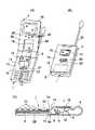
図1乃至図5を参照し、本発明の実施の形態に係わる携帯電話を説明する。先ず、図1を参照して本発明の第1の実施の形態の携帯電話を説明する。図1の(A)及び(B)は携帯電話の斜視図である。
【0026】
携帯電話は第1の本体1とこの第1の本体1に回動可能に支持されている第2の本体2とを備えている。第1の本体1と第2の本体2とは回動部3を介して接続されている。第2の本体2は第1の本体1の前面1aを覆う閉位置(図1の(B))と、第1の本体に対して所定角度を有した開位置(図1の(A))との間で回動する。
【0027】
図1の(C)は図1の(A)の1C−1C線で切断した第1の本体1の断面図である。第1の本体1には、電子回路が形成された基板4と、画像を投影するための画像表示部5とが内蔵されている。画像表示部5は、画像を表示する画像表示素子として用いられているLCD6と、LCD6に設けられているバックライト8と、LCD6により表示された画像を拡大する拡大光学系を有する拡大光学部10と、第1の本体1の前面1aに設けられており、拡大光学部10により拡大された画像を外部に導く観察窓12とを有している。LCD6により表示された画像を含んだ光は、図1の(C)の点線に沿って拡大光学部10内を伝搬し、観察窓12から外部に導かれる。LCD6とバックライト8とは適切な導線4aを介して基板4に接続されている。画像表示部5はQVGA、VGA等の高精細な画像の虚像を拡大して使用者の眼に投影することができる。
【0028】
前面1aにおいて、画像表示部5が内蔵されている部分には、前面1aから突出した観察突起部14が形成されている。これにより、例えば基板4等の他の部材よりも比較的厚い拡大光学部10が観察突起部14に覆われて、第1の本体1に内蔵される。観察窓12は観察突起部14に取り付けられており、外部を向いている。
【0029】
第2の本体は、上記閉位置のときに第1の本体と対向する前面2aと、前面2aとは反対側に位置する背面2bとを有している。閉位置のときに、第2の本体2において、第1の本体1の観察突起部14と対向する部分には、前面2aから背面2bに第2の本体2を貫く開口16が形成されている。これにより、第2の本体2の位置が開位置か閉位置かにかかわらず、観察窓12は外部に向いており、使用者は両位置において観察窓12を観察することができる。また、閉位置のときに観察突起部14が開口16に収納されることにより、携帯電話を折り畳んで携帯する際に突出した部分が形成されないので、比較的薄型の携帯電話が得られる。
【0030】
第2の本体2の前面2aにはLCD6よりも比較的低い解像度をもつ表示部18が設けられている。表示部18は従来の携帯電話に設けられた、拡大光学系を用いない液晶ディスプレイと同程度の解像度の表示領域を有している。
【0031】
第1の本体1の前面1aには、操作部20が配設されている。操作部20は複数の押しボタンを有しており、通常の発信操作や携帯電話の機能設定のために使用される。
【0032】
前面1aと背面2bとには夫々主操作部22と従操作部24とが配設されている。主操作部22は十字ボタンを有しており、少なくともLCD6により表示される画像を操作するのに使用される。主操作部22はブラウザのメニュー指示等のために用いられる。従操作部24は閉位置のときに主操作部22に対向する部分に配設されており、十字ボタンで構成されている。
【0033】
第2の本体2において、閉位置のときに主操作部22と従操作部24との間に位置する部分には、4つのピンで構成され、従操作部24から前面2aに延びている連結部材26が配設されている。閉位置のときには、連結部材26は主操作部22と従操作部24とを連結し、これにより、主操作部22と従操作部24とを連動させる。主操作部22と従操作部24と連結部材26とはポインティングデバイスを構成する。
【0034】
第1の本体1において、前面1aとは反対側の背面1bには電池28が取り付けられている。携帯電話はアンテナ30を有している。
【0035】
以上詳述した如く構成されている携帯電話の第1の実施の形態においては、使用者が携帯電話を単なる通信機器として使用したい場合は、LCD6で操作を確認しながら従来の携帯電話と同様に使用することにより目的を達成できる。一方インターネットなどの高精細表示が必要になる場合には、閉位置にして携帯電話を折り畳み、背面2bから観察可能な観察窓12をのぞき込むことにより所望の画像を観察できる。このときメニュー操作はポインティングデバイスの従操作部24により行うが、従操作部24の周辺には別の不要なボタン類が存在しないので、いちいち手元を確認しなくても確実な操作が可能となる。さらに観察窓12から十分に離れた位置に従操作部24を配置することにより操作性を向上させても良い。
【0036】
本実施の形態では、ポインティングデバイスは連結部材26により連結される主操作部22と従操作部24とを有しているが、本発明はこれに限定されるものではない。例えば、連結部材26を用いず、従操作部24を電子的に主操作部22に連動させても良い。この場合、操作部22,24は個別のポインティングデバイスとして機能する。また、主操作部22と従操作部24とは十字ボタン状の部材に限定されるものではなく、他の部材を有していても良い。
【0037】
また、本実施の形態では、画像表示部5は第1の本体1に内蔵されているが、画像表示部5は着脱可能に第1の本体1に支持されていても良い。
【0038】
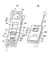
次に、図2を参照して本発明の第2の実施の形態の携帯電話を説明する。本実施の形態の構成の大部分は、基本的に第1の実施の形態の構成の大部分と同じである。尚、本実施の形態において、第1の実施の形態の図1の(A)、(B)及び(C)を参照して説明した構成部材と実質的に同一の構成部材は、第1の実施の形態の対応する構成部材を指示していた参照符号と同じ参照符号を付して詳細な説明を省略する。
【0039】
本実施の形態の構成が第1の実施の形態の構成と異なる点は、拡大光学部を覆う観察突起部の構成である。図2の(A)は開位置のときの携帯電話の斜視図、(B)は閉位置のときの携帯電話の斜視図である。第1の実施の形態の観察突起部14は、上述したように、閉位置のときに第2の本体2の前面2aに対向する位置に形成されており、開口16に収納される。
【0040】
これに対して、本実施の形態の観察突起部214は、前面1aにおいて、回動部3とは反対側に位置し、閉位置のときに第2の本体2により覆われない部分に形成されている。観察突起部214には観察窓12が取り付けられており、外部を向いている。
【0041】
このように構成しても第1の実施の形態と同様に、第2の本体2の位置が開位置か閉位置かにかかわらず、使用者は両位置において観察窓12を観察することができる。
【0042】
次に、図3を参照して本発明の第3の実施の形態の携帯電話を説明する。本実施の形態の構成の大部分は、基本的に第1の実施の形態の構成の大部分と同じである。尚、本実施の形態において、第1の実施の形態の図1の(A)、(B)及び(C)を参照して説明した構成部材と実質的に同一の構成部材は、第1の実施の形態の対応する構成部材を指示していた参照符号と同じ参照符号を付して詳細な説明を省略する。
【0043】
本実施の形態の構成が第1の実施の形態の構成と異なる点は、ポインティングデバイスの従操作部の構成である。図3の(A)は開位置のときの携帯電話の斜視図、(B)は閉位置のときの携帯電話の斜視図、そして(C)は(A)の3C−3C線で切断した第1の本体1の断面図である。第1の実施の形態では、従操作部24は連結部材26により主操作部22と連結され、主操作部22と連動する。従操作部24は第2の本体2の背面2bに配設されている。
【0044】
これに対して、本実施の形態では、連結部材は用いられておらず、第1の実施の形態の操作部22,24の代わりに、個別の2つのポインティングデバイス322,324が夫々配設されている。ポインティングデバイス322,324は互いに電子的に連動する。ポインティングデバイス324は第1の本体1の背面1bに配設されている。
【0045】
このように構成しても第1の実施の形態と同様に、観察窓12をのぞき込みながら、手元を確認しなくても確実な操作が可能となる。
【0046】
次に、図4を参照して本発明の第4の実施の形態の携帯電話を説明する。本実施の形態の構成の大部分は、基本的に第3の実施の形態の構成の大部分と同じである。尚、本実施の形態において、第3の実施の形態の図3の(A)、(B)及び(C)を参照して説明した構成部材と実質的に同一の構成部材は、第3の実施の形態の対応する構成部材を指示していた参照符号と同じ参照符号を付して詳細な説明を省略する。
【0047】
本実施の形態の構成が第3の実施の形態の構成と異なる点は、ポインティングデバイスの構成である。図4の(A)は開位置のときの携帯電話の斜視図、(B)は閉位置のときの携帯電話の斜視図である。第3の実施の形態では、ポインティングデバイス324は第1の本体1の背面1bに配設されており、十字ボタンで構成されている。
【0048】
これに対して、本実施の形態では、第3の実施の形態のポインティングデバイス324の代わりに、ピン状のポインティングデバイス424が第1の本体1において、前面1aと背面1bとの間に渡って延びている側面1cに配設されている。ポインティングデバイス424は2方向に回動可能である。
【0049】
このように構成しても第3の実施の形態と同様に、観察窓12をのぞき込みながら、確実な操作が可能となる。
【0050】
本実施の形態で、ポインティングデバイス424は側面1cに配設されているが、第2の本体2において、前面2aと背面2bとの間に渡って延びている側面2cに配設されていても良い。
【0051】
また、ポインティングデバイス424はピン状の部材に限定されるものではなく、他の部材で構成されていても良い。
【0052】
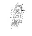
次に、図5を参照して本発明の第5の実施の形態の携帯電話を説明する。本実施の形態の構成の大部分は、基本的に第1の実施の形態の構成の大部分と同じである。尚、本実施の形態において、第1の実施の形態の図1の(A)、(B)及び(C)を参照して説明した構成部材と実質的に同一の構成部材は、第1の実施の形態の対応する構成部材を指示していた参照符号と同じ参照符号を付して詳細な説明を省略する。
【0053】
本実施の形態の構成が第1の実施の形態の構成と異なる点は、夫々の構成部材の配置である。本実施の形態では、第1の本体1に、画像表示部5と観察窓12と観察突起部14と表示部18と背面1bに配設された従操作部24(図示せず)と連結部材26とが設けられており、第2の本体2に、開口16と操作部20と主操作部22とが設けられている。
【0054】
このように構成しても第1の実施の形態と同様に、観察窓12をのぞき込みながら、手元を確認しなくても確実な操作が可能となる。
【0055】
本実施の形態では、ポインティングデバイスは主操作部22と背面1bに配設された従操作部24と連結部材26とを有しているが、ポインティングデバイスの構成はこれに限定されるものではない。例えば、個別の2つのポインティングデバイスが用いられており、一方のポインティングデバイスが第2の本体2の前面2aに配設され、他方のポインティングデバイスが第2の本体2の背面2bに配設されていても良い。また、一方のポインティングデバイスが第2の本体2の前面2aに配設され、他方のポインティングデバイスが、第1の本体1の側面1c又は第2の本体2の側面2cに配設されていても良い。
【0056】
本発明は、以下の各項に示す発明を開示している。
第1項.第1の本体とこの第1の本体に回動可能に支持されている第2の本体とを有している本体と、
画像を表示する画像表示素子と、この画像表示素子により表示された画像を拡大する拡大光学部と、前記第1の本体の表面に設けられており、前記拡大光学部により拡大された画像を外部に導く観察窓とを有している画像表示部と
を備えており、前記第2の本体は、前記第1の本体の表面の一部を覆う閉位置と、第1の本体に対して所定角度を有した開位置との間で回動する携帯電話において、
前記第1の本体に設けられた操作部と、
前記第2の本体に設けられており、前記画像表示素子よりも低い解像度をもつ表示部と、
少なくとも前記画像表示素子により表示される画像を操作するための1以上のポインティングデバイスと
を備えており、ポインティングデバイスの少なくとも1つと画像表示部の観察窓とは、第2の本体が閉位置に位置するときに外部に向くように配置されており、前記画像表示部は、本体に内蔵されているか、又は着脱可能に本体に支持されていることを特徴とする携帯電話。
第2項.前記第1の本体は、前記第2の本体が閉位置に位置するときに第2の本体により覆われる前面と、この前面とは反対側に位置する背面とを有しており、前記ポインティングデバイスは、第1の本体のこの背面に配置されていることを特徴とする第1項に記載の携帯電話。
第3項.前記第2の本体は、第2の本体が閉位置に位置するときに前記第1の本体と対向する前面と、この前面とは反対側に位置する背面とを有しており、前記ポインティングデバイスは、第2の本体のこの背面に配置されていることを特徴とする第1項に記載の携帯電話。
第4項.前記第2の本体は、第2の本体が閉位置に位置するときに前記第1の本体と対向する前面と、この前面とは反対側に位置する背面とを有しており、前記ポインティングデバイスは、
少なくとも前記画像表示素子により表示される画像を操作するための主操作部と、
第2の本体の背面に配置されている従操作部と、
この従操作部と前記主操作部とを連結する連結部材と
を有しており、主操作部と従操作部とは連動することを特徴とする第1項に記載の携帯電話。
第5項.前記第1の本体は、前記第2の本体が閉位置に位置するときに第2の本体により覆われる前面と、この前面とは反対側に位置する背面と、この背面と前記前面との間に渡って延びている側面とを有しており、
前記第2の本体は、第2の本体が閉位置に位置するときに前記第1の本体と対向する前面と、この前面とは反対側に位置する背面と、この背面と前記前面との間に渡って延びている側面とを有しており、
前記ポインティングデバイスは、第1の本体の前記側面又は第2の本体の前記側面に配置されていることを特徴とする第1項に記載の携帯電話。
第6項.前記第1の本体は、前記第2の本体が閉位置に位置するときに第2の本体により覆われる前面を有しており、
前記第2の本体は、第2の本体が閉位置に位置するときに前記第1の本体と対向する前面と、この前面とは反対側に位置する背面とを有しており、
前記観察窓は第1の本体の前面に設けられており、第2の本体が閉位置に位置するときに、第2の本体2において、観察窓と対向する部分には、前面から背面に第2の本体を貫く開口が設けられており、第2の本体が閉位置に位置するときに、観察窓はこの開口から外部に向くことを特徴とする第1項乃至第5項のいずれか1項に記載の携帯電話。
第7項.第1の本体とこの第1の本体に回動可能に支持されている第2の本体とを有している本体と、
画像を表示する画像表示素子と、この画像表示素子により表示された画像を拡大する拡大光学部と、前記第1の本体の表面に設けられており、前記拡大光学部により拡大された画像を外部に導く観察窓とを有している画像表示部と
を備えており、前記第2の本体は、前記第1の本体の表面の一部を覆う閉位置と、第1の本体に対して所定角度を有した開位置との間で回動する携帯電話において、
前記第2の本体に設けられた操作部と、
前記第1の本体に設けられており、前記画像表示素子よりも低い解像度をもつ表示部と、
少なくとも前記画像表示素子により表示される画像を操作するための1以上のポインティングデバイスと
を備えており、ポインティングデバイスの少なくとも1つと画像表示部の観察窓とは、第2の本体が閉位置に位置するときに外部に向くように配置されており、前記画像表示部は、本体に内蔵されているか、又は着脱可能に本体に支持されていることを特徴とする携帯電話。
第8項.前記第1の本体は、前記第2の本体が閉位置に位置するときに第2の本体により覆われる前面と、この前面とは反対側に位置する背面とを有しており、前記ポインティングデバイスは、第1の本体のこの背面に配置されていることを特徴とする第7項に記載の携帯電話。
第9項.前記第2の本体は、第2の本体が閉位置に位置するときに前記第1の本体と対向する前面と、この前面とは反対側に位置する背面とを有しており、前記ポインティングデバイスは、第2の本体のこの背面に配置されていることを特徴とする第7項に記載の携帯電話。
第10項.前記第1の本体は、前記第2の本体が閉位置に位置するときに第2の本体により覆われる前面と、この前面とは反対側に位置する背面とを有しており、前記ポインティングデバイスは、
少なくとも前記画像表示素子により表示される画像を操作するための主操作部と、
第1の本体の背面に配置されている従操作部と、
この従操作部と前記主操作部とを連結する連結部材と
を有しており、主操作部と従操作部とは連動することを特徴とする第7項に記載の携帯電話。
第11項.前記第1の本体は、前記第2の本体が閉位置に位置するときに第2の本体により覆われる前面と、この前面とは反対側に位置する背面と、この背面と前記前面との間に渡って延びている側面とを有しており、
前記第2の本体は、第2の本体が閉位置に位置するときに前記第1の本体と対向する前面と、この前面とは反対側に位置する背面と、この背面と前記前面との間に渡って延びている側面とを有しており、
前記ポインティングデバイスは、第1の本体の前記側面又は第2の本体の前記側面に配置されていることを特徴とする第7項に記載の携帯電話。
第12項.前記第1の本体は、前記第2の本体が閉位置に位置するときに第2の本体により覆われる前面を有しており、
前記第2の本体は、第2の本体が閉位置に位置するときに前記第1の本体と対向する前面と、この前面とは反対側に位置する背面とを有しており、
前記観察窓は第1の本体の前面に設けられており、第2の本体が閉位置に位置するときに、第2の本体2において、観察窓と対向する部分には、前面から背面に第2の本体を貫く開口が設けられており、第2の本体が閉位置に位置するときに、観察窓はこの開口から外部に向くことを特徴とする第7項乃至第11項のいずれか1項に記載の携帯電話。
尚、本発明は上述した実施の形態に限定されるものではなく、発明の趣旨を逸脱しない範囲内において種々の変形や応用が可能であることは勿論である。
【0057】
【発明の効果】
以上のような構成によれば、高精細な画像が観察可能で、特に操作性が良く、携帯時に凹凸がない比較的薄型の携帯電話が得られる。
【図面の簡単な説明】
【図1】(A)は本発明の第1の実施の形態における携帯電話の開位置のときの斜視図、(B)は(A)の携帯電話の閉位置のときの斜視図、そして(C)は(A)の1C−1C線で切断して示した断面図。
【図2】(A)は本発明の第2の実施の形態における携帯電話の開位置のときの斜視図、(B)は(A)の携帯電話の閉位置のときの斜視図。
【図3】(A)は本発明の第3の実施の形態における携帯電話の開位置のときの斜視図、(B)は(A)の携帯電話の閉位置のときの斜視図、そして(C)は(A)の3C−3C線で切断して示した断面図。
【図4】(A)は本発明の第4の実施の形態における携帯電話の開位置のときの斜視図、(B)は(A)の携帯電話の閉位置のときの斜視図。
【図5】本発明の第5の実施の形態における携帯電話の開位置のときの斜視図。
【図6】従来の携帯型通信用受信機の斜視図。
【図7】携帯型の電話機が接続できる従来の携帯電源の斜視図。
【図8】従来の携帯型の電話機を使用者の頭部に装着した状態を示す斜視図。
【図9】別の従来の携帯型の電話機の斜視図。
【符号の説明】
1 第1の本体
2 第2の本体
5 画像表示部
6 LCD
10 拡大光学部
12 観察窓
18 表示部
20 操作部
22 主操作部
24 従操作部
26 連結部材
322 ポインティングデバイス
324 ポインティングデバイス
424 ポインティングデバイス[0001]
BACKGROUND OF THE INVENTION
The present invention relates to a mobile phone having a magnifying optical system and having a display unit capable of displaying high-definition data built-in or detachably supported.
[0002]
[Prior art]
In recent years, there has been an increasing demand for browsing information on the Internet using a mobile phone, for example. Along with this, colorization and high definition of display elements mounted on mobile phones are progressing. Among them, there has been proposed an apparatus that uses a high-definition and small display element having a screen size of about 1 inch or less, such as QVGA and VGA, and observes the display image using an enlarged optical system.
[0003]
Hereinafter, a conventional technique will be described with reference to FIGS. JP-A-5-259964 discloses a portable communication receiver having a small
[0004]
In addition, for an external display device that is separate from the main body and provides a higher definition screen than the display unit mounted on the main body, the display screen is used as it is by using a liquid crystal of about 2 inches. Mobile phones to be observed have been released.
[0005]
Japanese Patent Laid-Open No. 10-123969 discloses a portable power source that functions as an accessory of a portable electronic device and incorporates a micro
[0006]
Japanese Patent Laid-Open No. 2-100448 discloses a portable telephone including a virtual image visual display means 802 in an L-
[0007]
Japanese Patent Application Laid-Open No. 11-327462 discloses a portable telephone in which a display unit for enlarging a virtual image is foldable as shown in FIG.
[0008]
[Problems to be solved by the invention]
However, the conventional telephone has the following problems. Generally, a viewer-equipped telephone that projects a virtual image is used in such a manner that the display unit is looked into. This is because if the eye point is taken large, the optical system becomes large and portability deteriorates. On the other hand, when browsing content, it is necessary to perform menu operations of browser software and the like, and some pointing device is used for this purpose. Therefore, the user observes the screen with the telephone set close to the face and operates the pointing device, and the operability of the telephone as shown in FIGS. 7, 8, and 9 is poor. In particular, when the telephone is downsized, the operability becomes worse when the operation buttons are close to each other.
[0009]
On the other hand, in the separate portable communication receiver as shown in FIG. 1, the operability is relatively secured by installing the pointing device on the
[0010]
In addition, since the above-mentioned conventional telephone incorporates a magnifying optical system into the device, a high-resolution image can be observed, but the device is particularly thick in the thickness direction as compared with the case of using a normal LCD. A malfunction occurs.
[0011]
Furthermore, as described above, the observation of the image with the magnifying optical system requires the phone to be close to the face for the reasons described above, so it is greatly different from the conventional usability, and in the first place, simply confirming the dial or selecting the function of the main unit, High resolution display is not required for applications such as setting. That is, there is a conflicting demand for viewing a high-resolution screen and a desire for easy use with a simple operation, and a telephone that satisfies these requirements and is easy to use is desired.
[0012]
The present invention has been made in view of the above-described problems, and provides a mobile phone in which a display unit capable of displaying high-definition data is built-in or detachably supported and has good operability. For the purpose.
[0013]
[Means for Solving the Problems]
In order to achieve the above object, a mobile phone according to
An image display element that displays an image, a magnifying optical unit that magnifies an image displayed by the image display element, and a surface of the first main body, and the image magnified by the magnifying optical unit is externally provided. An image display unit having an observation window that leads to a closed position, wherein the second main body covers a part of the surface of the first main body and a predetermined position with respect to the first main body. In a mobile phone that rotates between an open position with an angle,
An operation unit provided in the first main body;
A display unit provided in the second main body, having a lower resolution than the image display element;
And at least one pointing device for manipulating an image displayed by the image display element, and at least one of the pointing device and the observation window of the image display unit are located in a closed position. The image display unit is built in the main body or detachably supported by the main body.
[0014]
With this configuration, the display unit capable of displaying high-definition data is built-in or detachably supported regardless of whether the position of the second main body is the open position or the closed position. A mobile phone that secures easy operability can be provided.
[0015]
In the mobile phone according to
[0016]
In the mobile phone according to
[0017]
In the cellular phone according to
A main operation unit for operating at least an image displayed by the image display element;
A slave operation unit disposed on the back surface of the second main body;
It has the connection member which connects this subordinate operation part and the above-mentioned main operation part, and the main operation part and the subordinate operation part interlock | cooperate, It is characterized by the above-mentioned.
[0018]
In the mobile phone according to
The second body includes a front surface facing the first body when the second body is in the closed position, a back surface opposite to the front surface, and between the back surface and the front surface. And a side surface extending over
The pointing device is arranged on the side surface of the first main body or the side surface of the second main body.
[0019]
In a mobile phone according to
An image display element that displays an image, a magnifying optical unit that magnifies an image displayed by the image display element, and a surface of the first main body, and the image magnified by the magnifying optical unit is externally provided. An image display unit having an observation window that leads to a closed position, wherein the second main body covers a part of the surface of the first main body and a predetermined position with respect to the first main body. In a mobile phone that rotates between an open position with an angle,
An operation unit provided in the second main body;
A display unit provided in the first main body and having a lower resolution than the image display element;
And at least one pointing device for manipulating an image displayed by the image display element, and at least one of the pointing device and the observation window of the image display unit are located in a closed position. The image display unit is built in the main body or detachably supported by the main body.
[0020]
With this configuration, the display unit capable of displaying high-definition data is built-in or detachably supported regardless of whether the position of the second main body is the open position or the closed position. A mobile phone that secures easy operability can be provided.
[0021]
In the cellular phone according to claim 7 of the present invention, the first main body has a front surface covered by the second main body when the second main body is located at the closed position, and an opposite side of the front surface. And the pointing device is arranged on the back surface of the first body.
[0022]
In the cellular phone according to
[0023]
In the mobile phone according to claim 9 of the present invention, the first main body includes a front surface covered by the second main body when the second main body is located at the closed position, and a side opposite to the front surface. And a pointing device, the pointing device comprising:
A main operation unit for operating at least an image displayed by the image display element;
A slave operation unit disposed on the back of the first body;
It has the connection member which connects this subordinate operation part and the above-mentioned main operation part, and the main operation part and the subordinate operation part interlock | cooperate, It is characterized by the above-mentioned.
[0024]
In the mobile phone according to claim 10 of the present invention, the first main body has a front surface covered by the second main body when the second main body is located in the closed position, and the opposite side of the front surface. A back surface located and a side surface extending between the back surface and the front surface;
The second body includes a front surface facing the first body when the second body is in the closed position, a back surface opposite to the front surface, and between the back surface and the front surface. And a side surface extending over
The pointing device is arranged on the side surface of the first main body or the side surface of the second main body.
[0025]
DETAILED DESCRIPTION OF THE INVENTION
A mobile phone according to an embodiment of the present invention will be described with reference to FIGS. First, a mobile phone according to a first embodiment of the present invention will be described with reference to FIG. 1A and 1B are perspective views of a mobile phone.
[0026]
The mobile phone includes a first
[0027]
1C is a cross-sectional view of the first
[0028]
On the
[0029]
The second body has a
[0030]
A
[0031]
An
[0032]
A
[0033]
In the second
[0034]
In the first
[0035]
In the first embodiment of the cellular phone configured as described in detail above, when the user wants to use the cellular phone as a mere communication device, the user confirms the operation on the
[0036]
In the present embodiment, the pointing device includes the
[0037]
In the present embodiment, the
[0038]
Next, a mobile phone according to a second embodiment of the present invention will be described with reference to FIG. Most of the configuration of the present embodiment is basically the same as most of the configuration of the first embodiment. In the present embodiment, substantially the same components as those described with reference to FIGS. 1A, 1B, and 1C of the first embodiment are the same as those in the first embodiment. The same reference numerals as those used for designating the corresponding constituent members in the embodiment are attached, and detailed description thereof is omitted.
[0039]
The configuration of the present embodiment is different from the configuration of the first embodiment in the configuration of the observation protrusion that covers the magnifying optical unit. 2A is a perspective view of the mobile phone in the open position, and FIG. 2B is a perspective view of the mobile phone in the closed position. As described above, the
[0040]
On the other hand, the
[0041]
Even in such a configuration, the user can observe the
[0042]
Next, a mobile phone according to a third embodiment of the present invention will be described with reference to FIG. Most of the configuration of the present embodiment is basically the same as most of the configuration of the first embodiment. In the present embodiment, substantially the same components as those described with reference to FIGS. 1A, 1B, and 1C of the first embodiment are the same as those in the first embodiment. The same reference numerals as those used for designating the corresponding constituent members in the embodiment are attached, and detailed description thereof is omitted.
[0043]
The configuration of the present embodiment is different from the configuration of the first embodiment in the configuration of the slave operation unit of the pointing device. 3A is a perspective view of the mobile phone in the open position, FIG. 3B is a perspective view of the mobile phone in the closed position, and FIG. 3C is a sectional view taken along
[0044]
In contrast, in the present embodiment, no connecting member is used, and instead of the
[0045]
Even with this configuration, as in the first embodiment, a reliable operation is possible without looking at the hand while looking into the
[0046]
Next, a mobile phone according to a fourth embodiment of the present invention will be described with reference to FIG. Most of the configuration of the present embodiment is basically the same as most of the configuration of the third embodiment. In the present embodiment, substantially the same components as those described with reference to FIGS. 3A, 3B, and 3C of the third embodiment are the same as those in the third embodiment. The same reference numerals as those used for designating the corresponding constituent members in the embodiment are attached, and detailed description thereof is omitted.
[0047]
The configuration of the present embodiment is different from the configuration of the third embodiment in the configuration of the pointing device. 4A is a perspective view of the mobile phone in the open position, and FIG. 4B is a perspective view of the mobile phone in the closed position. In the third embodiment, the
[0048]
On the other hand, in this embodiment, instead of the
[0049]
Even with this configuration, as in the third embodiment, a reliable operation is possible while looking into the
[0050]
In the present embodiment, the
[0051]
The
[0052]
Next, a mobile phone according to a fifth embodiment of the present invention will be described with reference to FIG. Most of the configuration of the present embodiment is basically the same as most of the configuration of the first embodiment. In the present embodiment, substantially the same components as those described with reference to FIGS. 1A, 1B, and 1C of the first embodiment are the same as those in the first embodiment. The same reference numerals as those used for designating the corresponding constituent members in the embodiment are attached, and detailed description thereof is omitted.
[0053]
The configuration of the present embodiment is different from the configuration of the first embodiment in the arrangement of the respective constituent members. In the present embodiment, the first
[0054]
Even with this configuration, as in the first embodiment, a reliable operation is possible without looking at the hand while looking into the
[0055]
In the present embodiment, the pointing device includes the
[0056]
The present invention discloses the invention shown in the following items.
An image display element that displays an image, a magnifying optical unit that magnifies an image displayed by the image display element, and a surface of the first main body, and the image magnified by the magnifying optical unit is externally provided. An image display unit having an observation window that leads to a closed position, wherein the second main body covers a part of the surface of the first main body and a predetermined position with respect to the first main body. In a mobile phone that rotates between an open position with an angle,
An operation unit provided in the first main body;
A display unit provided in the second main body, having a lower resolution than the image display element;
And at least one pointing device for manipulating an image displayed by the image display element, and at least one of the pointing device and the observation window of the image display unit are located in a closed position. The cellular phone is arranged so as to face outward when the image display unit is built in the main body or is detachably supported by the main body.
A main operation unit for operating at least an image displayed by the image display element;
A slave operation unit disposed on the back surface of the second main body;
2. The mobile phone according to
The second body includes a front surface facing the first body when the second body is in the closed position, a back surface opposite to the front surface, and between the back surface and the front surface. And a side surface extending over
2. The mobile phone according to
The second body has a front surface that faces the first body when the second body is in the closed position, and a back surface that is located on the opposite side of the front surface.
The observation window is provided on the front surface of the first main body. When the second main body is in the closed position, the second
Item 7. A main body having a first main body and a second main body rotatably supported by the first main body;
An image display element that displays an image, a magnifying optical unit that magnifies an image displayed by the image display element, and a surface of the first main body, and the image magnified by the magnifying optical unit is externally provided. An image display unit having an observation window that leads to a closed position, wherein the second main body covers a part of the surface of the first main body and a predetermined position with respect to the first main body. In a mobile phone that rotates between an open position with an angle,
An operation unit provided in the second main body;
A display unit provided in the first main body and having a lower resolution than the image display element;
And at least one pointing device for manipulating an image displayed by the image display element, and at least one of the pointing device and the observation window of the image display unit are located in a closed position. The cellular phone is arranged so as to face outward when the image display unit is built in the main body or is detachably supported by the main body.
Item 9. The second body has a front surface that faces the first body when the second body is in the closed position, and a back surface that is located on the opposite side of the front surface, and the pointing device The mobile phone according to item 7, wherein the mobile phone is disposed on the back surface of the second main body.
A main operation unit for operating at least an image displayed by the image display element;
A slave operation unit disposed on the back of the first body;
8. The mobile phone according to claim 7, further comprising a connecting member that connects the sub operation unit and the main operation unit, wherein the main operation unit and the sub operation unit are interlocked.
Item 11. The first body includes a front surface covered by the second body when the second body is in a closed position, a back surface opposite to the front surface, and a space between the back surface and the front surface. And a side surface extending over
The second body includes a front surface facing the first body when the second body is in the closed position, a back surface opposite to the front surface, and between the back surface and the front surface. And a side surface extending over
The mobile phone according to claim 7, wherein the pointing device is disposed on the side surface of the first main body or the side surface of the second main body.
The second body has a front surface that faces the first body when the second body is in the closed position, and a back surface that is located on the opposite side of the front surface.
The observation window is provided on the front surface of the first main body. When the second main body is in the closed position, the second
It should be noted that the present invention is not limited to the above-described embodiment, and it is needless to say that various modifications and applications can be made without departing from the spirit of the invention.
[0057]
【The invention's effect】
According to the configuration described above, a high-definition image can be observed, a operability is particularly good, and a relatively thin mobile phone having no unevenness when carried can be obtained.
[Brief description of the drawings]
FIG. 1A is a perspective view of a mobile phone in an open position according to the first embodiment of the present invention, FIG. 1B is a perspective view of a mobile phone in a closed position of FIG. C is a cross-sectional view taken along
2A is a perspective view when the mobile phone is in an open position according to a second embodiment of the present invention, and FIG. 2B is a perspective view when the mobile phone is closed in FIG.
3A is a perspective view when the mobile phone is in an open position according to a third embodiment of the present invention, FIG. 3B is a perspective view when the mobile phone is closed in FIG. C) is a cross-sectional view taken along
4A is a perspective view when the mobile phone is in an open position according to a fourth embodiment of the present invention, and FIG. 4B is a perspective view when the mobile phone is closed in FIG.
FIG. 5 is a perspective view when the mobile phone is in an open position according to a fifth embodiment of the present invention.
FIG. 6 is a perspective view of a conventional portable communication receiver.
FIG. 7 is a perspective view of a conventional portable power source to which a portable telephone can be connected.
FIG. 8 is a perspective view showing a state in which a conventional portable telephone is mounted on a user's head.
FIG. 9 is a perspective view of another conventional portable telephone.
[Explanation of symbols]
DESCRIPTION OF
DESCRIPTION OF
Claims (10)
Translated fromJapanese画像を表示する画像表示素子と、この画像表示素子により表示された画像を拡大する拡大光学部と、前記第1の本体の表面に設けられており、前記拡大光学部により拡大された画像を外部に導く観察窓とを有している画像表示部と
を備えており、前記第2の本体は、前記第1の本体の表面の一部を覆う閉位置と、第1の本体に対して所定角度を有した開位置との間で回動する携帯電話において、
前記第1の本体に設けられた操作部と、
前記第2の本体に設けられており、前記画像表示素子よりも低い解像度をもつ表示部と、
少なくとも前記画像表示素子により表示される画像を操作するための1以上のポインティングデバイスと
を備えており、ポインティングデバイスの少なくとも1つと画像表示部の観察窓とは、第2の本体が閉位置に位置するときに外部に向くように配置されており、前記画像表示部は、本体に内蔵されているか、又は着脱可能に本体に支持されていることを特徴とする携帯電話。A main body having a first main body and a second main body rotatably supported by the first main body;
An image display element that displays an image, a magnifying optical unit that magnifies an image displayed by the image display element, and a surface of the first main body, and the image magnified by the magnifying optical unit is externally provided. An image display unit having an observation window that leads to a closed position, wherein the second main body covers a part of the surface of the first main body and a predetermined position with respect to the first main body. In a mobile phone that rotates between an open position with an angle,
An operation unit provided in the first main body;
A display unit provided in the second main body, having a lower resolution than the image display element;
And at least one pointing device for manipulating an image displayed by the image display element, and at least one of the pointing device and the observation window of the image display unit are located in a closed position. The cellular phone is arranged so as to face outward when the image display unit is built in the main body or is detachably supported by the main body.
少なくとも前記画像表示素子により表示される画像を操作するための主操作部と、
第2の本体の背面に配置されている従操作部と、
この従操作部と前記主操作部とを連結する連結部材と
を有しており、主操作部と従操作部とは連動することを特徴とする請求項1に記載の携帯電話。The second body has a front surface that faces the first body when the second body is in the closed position, and a back surface that is located on the opposite side of the front surface, and the pointing device Is
A main operation unit for operating at least an image displayed by the image display element;
A slave operation unit disposed on the back surface of the second main body;
The mobile phone according to claim 1, further comprising a connecting member that connects the sub operation unit and the main operation unit, wherein the main operation unit and the sub operation unit are interlocked.
前記第2の本体は、第2の本体が閉位置に位置するときに前記第1の本体と対向する前面と、この前面とは反対側に位置する背面と、この背面と前記前面との間に渡って延びている側面とを有しており、
前記ポインティングデバイスは、第1の本体の前記側面又は第2の本体の前記側面に配置されていることを特徴とする請求項1に記載の携帯電話。The first body includes a front surface covered by the second body when the second body is in a closed position, a back surface opposite to the front surface, and a space between the back surface and the front surface. And a side surface extending over
The second body includes a front surface facing the first body when the second body is in the closed position, a back surface opposite to the front surface, and between the back surface and the front surface. And a side surface extending over
The mobile phone according to claim 1, wherein the pointing device is disposed on the side surface of the first main body or the side surface of the second main body.
画像を表示する画像表示素子と、この画像表示素子により表示された画像を拡大する拡大光学部と、前記第1の本体の表面に設けられており、前記拡大光学部により拡大された画像を外部に導く観察窓とを有している画像表示部と
を備えており、前記第2の本体は、前記第1の本体の表面の一部を覆う閉位置と、第1の本体に対して所定角度を有した開位置との間で回動する携帯電話において、
前記第2の本体に設けられた操作部と、
前記第1の本体に設けられており、前記画像表示素子よりも低い解像度をもつ表示部と、
少なくとも前記画像表示素子により表示される画像を操作するための1以上のポインティングデバイスと
を備えており、ポインティングデバイスの少なくとも1つと画像表示部の観察窓とは、第2の本体が閉位置に位置するときに外部に向くように配置されており、前記画像表示部は、本体に内蔵されているか、又は着脱可能に本体に支持されていることを特徴とする携帯電話。A main body having a first main body and a second main body rotatably supported by the first main body;
An image display element that displays an image, a magnifying optical unit that magnifies an image displayed by the image display element, and a surface of the first main body, and the image magnified by the magnifying optical unit is externally provided. An image display unit having an observation window that leads to a closed position, wherein the second main body covers a part of the surface of the first main body and a predetermined position with respect to the first main body. In a mobile phone that rotates between an open position with an angle,
An operation unit provided in the second main body;
A display unit provided in the first main body and having a lower resolution than the image display element;
And at least one pointing device for manipulating an image displayed by the image display element, and at least one of the pointing device and the observation window of the image display unit are located in a closed position. The cellular phone is arranged so as to face outward when the image display unit is built in the main body or is detachably supported by the main body.
少なくとも前記画像表示素子により表示される画像を操作するための主操作部と、
第1の本体の背面に配置されている従操作部と、
この従操作部と前記主操作部とを連結する連結部材と
を有しており、主操作部と従操作部とは連動することを特徴とする請求項6に記載の携帯電話。The first body has a front surface covered by the second body when the second body is in the closed position, and a back surface located on the opposite side of the front surface, and the pointing device Is
A main operation unit for operating at least an image displayed by the image display element;
A slave operation unit disposed on the back of the first body;
The mobile phone according to claim 6, further comprising: a connecting member that connects the sub operation unit and the main operation unit, wherein the main operation unit and the sub operation unit are interlocked.
前記第2の本体は、第2の本体が閉位置に位置するときに前記第1の本体と対向する前面と、この前面とは反対側に位置する背面と、この背面と前記前面との間に渡って延びている側面とを有しており、
前記ポインティングデバイスは、第1の本体の前記側面又は第2の本体の前記側面に配置されていることを特徴とする請求項6に記載の携帯電話。The first body includes a front surface covered by the second body when the second body is in a closed position, a back surface opposite to the front surface, and a space between the back surface and the front surface. And a side surface extending over
The second body includes a front surface facing the first body when the second body is in the closed position, a back surface opposite to the front surface, and between the back surface and the front surface. And a side surface extending over
The mobile phone according to claim 6, wherein the pointing device is disposed on the side surface of the first main body or the side surface of the second main body.
Priority Applications (2)
| Application Number | Priority Date | Filing Date | Title |
|---|---|---|---|
| JP2001055610AJP4414604B2 (en) | 2001-02-28 | 2001-02-28 | mobile phone |
| US10/084,538US20020140681A1 (en) | 2001-02-28 | 2002-02-26 | Mobile information terminal apparatus |
Applications Claiming Priority (1)
| Application Number | Priority Date | Filing Date | Title |
|---|---|---|---|
| JP2001055610AJP4414604B2 (en) | 2001-02-28 | 2001-02-28 | mobile phone |
Publications (2)
| Publication Number | Publication Date |
|---|---|
| JP2002261898A JP2002261898A (en) | 2002-09-13 |
| JP4414604B2true JP4414604B2 (en) | 2010-02-10 |
Family
ID=18915772
Family Applications (1)
| Application Number | Title | Priority Date | Filing Date |
|---|---|---|---|
| JP2001055610AExpired - Fee RelatedJP4414604B2 (en) | 2001-02-28 | 2001-02-28 | mobile phone |
Country Status (2)
| Country | Link |
|---|---|
| US (1) | US20020140681A1 (en) |
| JP (1) | JP4414604B2 (en) |
Families Citing this family (6)
| Publication number | Priority date | Publication date | Assignee | Title |
|---|---|---|---|---|
| KR100382938B1 (en) | 2001-06-21 | 2003-05-09 | 엘지전자 주식회사 | Folder type mobile phone added sub-display |
| USD484475S1 (en) | 2002-11-01 | 2003-12-30 | Nokia Corporation | Handset |
| IES20030805A2 (en)* | 2003-10-24 | 2005-04-20 | Laurence Byrne | Mobile communication device |
| KR20060027422A (en)* | 2004-09-22 | 2006-03-28 | 주식회사 팬택 | Foldable personal digital assistant |
| JP4408845B2 (en)* | 2005-07-27 | 2010-02-03 | シャープ株式会社 | Video composition apparatus and program |
| WO2007030828A2 (en)* | 2005-09-09 | 2007-03-15 | George Caraian | Mobile pointing device |
Family Cites Families (5)
| Publication number | Priority date | Publication date | Assignee | Title |
|---|---|---|---|---|
| JP3739821B2 (en)* | 1993-10-04 | 2006-01-25 | モトローラ・インコーポレイテッド | Transceiver with small virtual image display |
| JP3606498B2 (en)* | 1996-04-26 | 2005-01-05 | 三菱電機株式会社 | Portable information terminal device |
| US5818634A (en)* | 1996-08-05 | 1998-10-06 | Motorola, Inc. | Dual mode optical Magnifier system |
| JP3439086B2 (en)* | 1997-09-10 | 2003-08-25 | 松下電器産業株式会社 | Simple mobile phone |
| US6230028B1 (en)* | 1999-01-29 | 2001-05-08 | Sony Coporation | Simplification of portable radio telephone's operation |
- 2001
- 2001-02-28JPJP2001055610Apatent/JP4414604B2/ennot_activeExpired - Fee Related
- 2002
- 2002-02-26USUS10/084,538patent/US20020140681A1/ennot_activeAbandoned
Also Published As
| Publication number | Publication date |
|---|---|
| US20020140681A1 (en) | 2002-10-03 |
| JP2002261898A (en) | 2002-09-13 |
Similar Documents
| Publication | Publication Date | Title |
|---|---|---|
| US7808549B2 (en) | Electronic device | |
| JP4162683B2 (en) | Foldable mobile terminal | |
| EP1749392B1 (en) | Multi-function two panel electronic device with 360° relative motion | |
| EP1186111B1 (en) | Personal digital assistant/telephone combination device | |
| US20060056141A1 (en) | Portable electronic device | |
| US20070167197A1 (en) | Portable electronic device | |
| WO2007080775A1 (en) | Foldable portable device | |
| KR100377003B1 (en) | Folder type portable flat display device | |
| JP4414604B2 (en) | mobile phone | |
| JP5561168B2 (en) | Portable terminal device, state switching structure of portable terminal device | |
| JP2009171085A (en) | Electronic device | |
| JP4123994B2 (en) | Mobile phone | |
| JP4573024B2 (en) | Mobile device | |
| JP2004198472A (en) | Display device and information device using the same | |
| CN117561708A (en) | Electronic device, foldable slider device, and information display method | |
| CN1985501A (en) | Folding rotary portable terminal | |
| KR100429449B1 (en) | Portable Multi-Display Device | |
| JP3555854B2 (en) | Mobile phone | |
| JP4887766B2 (en) | Mobile device | |
| JP5121742B2 (en) | Display device | |
| WO2006045987A1 (en) | Foldable electronic device | |
| KR20090070439A (en) | Hinge and mobile terminal having him | |
| JP2003209605A (en) | Mobile phone | |
| JP2003169114A (en) | Portable telephone set | |
| KR20080082760A (en) | Mobile terminal with transparent display window |
Legal Events
| Date | Code | Title | Description |
|---|---|---|---|
| A621 | Written request for application examination | Free format text:JAPANESE INTERMEDIATE CODE: A621 Effective date:20080125 | |
| A977 | Report on retrieval | Free format text:JAPANESE INTERMEDIATE CODE: A971007 Effective date:20091008 | |
| TRDD | Decision of grant or rejection written | ||
| A01 | Written decision to grant a patent or to grant a registration (utility model) | Free format text:JAPANESE INTERMEDIATE CODE: A01 Effective date:20091027 | |
| A01 | Written decision to grant a patent or to grant a registration (utility model) | Free format text:JAPANESE INTERMEDIATE CODE: A01 | |
| A61 | First payment of annual fees (during grant procedure) | Free format text:JAPANESE INTERMEDIATE CODE: A61 Effective date:20091120 | |
| FPAY | Renewal fee payment (event date is renewal date of database) | Free format text:PAYMENT UNTIL: 20121127 Year of fee payment:3 | |
| LAPS | Cancellation because of no payment of annual fees |