JP4412718B2 - Information processing apparatus and control method thereof - Google Patents
Information processing apparatus and control method thereofDownload PDFInfo
- Publication number
- JP4412718B2 JP4412718B2JP2004171764AJP2004171764AJP4412718B2JP 4412718 B2JP4412718 B2JP 4412718B2JP 2004171764 AJP2004171764 AJP 2004171764AJP 2004171764 AJP2004171764 AJP 2004171764AJP 4412718 B2JP4412718 B2JP 4412718B2
- Authority
- JP
- Japan
- Prior art keywords
- job
- image processing
- sub
- processing apparatus
- processing
- Prior art date
- Legal status (The legal status is an assumption and is not a legal conclusion. Google has not performed a legal analysis and makes no representation as to the accuracy of the status listed.)
- Expired - Fee Related
Links
Images


Landscapes
- Facsimiles In General (AREA)
- Accessory Devices And Overall Control Thereof (AREA)
Description
Translated fromJapanese本発明は、画像処理システム及び画像処理システムにおける分散処理方法に関し、より詳細には、グリッドコンピューティング技術のフレームワークを使用して、複数の画像処理装置と、少なくとも1つの情報処理装置とが互いに接続された画像処理システムの画像処理装置を有効活用する技術に関するものである。 The present invention relates to an image processing system and a distributed processing method in the image processing system, and more specifically, a plurality of image processing apparatuses and at least one information processing apparatus are mutually connected using a framework of grid computing technology. The present invention relates to a technique for effectively using an image processing apparatus of a connected image processing system.
近年、印刷機能や複写機能に加え、ファクシミリ機能やスキャナ機能を備えたMFP(Multi Function Peripheral:複合機とも呼ばれる)等の画像処理装置(画像形成装置)の普及が進みオフィス等に導入されている。このような画像処理装置は、LAN等のネットワークに接続され、サーバ等を介して複数のPC(パーソナルコンピュータ)から使用できるように設置されるのが一般的である。 In recent years, image processing apparatuses (image forming apparatuses) such as MFPs (Multi Function Peripherals), which have a facsimile function and a scanner function in addition to a printing function and a copying function, have been widely used and introduced in offices and the like. . Such an image processing apparatus is generally installed so as to be connected to a network such as a LAN and used from a plurality of PCs (personal computers) via a server or the like.
最近では、このような環境においてネットワークで相互接続された複数の画像処理装置を連携活用することによって、システム全体の処理能力を有効活用する分散印刷も提案されており、例えば、ジョブ毎の履歴を参照して、次ジョブは先行処理したジョブと素性や属性が類似したジョブの処理実績から分散対象を検索する技術も提案されている(特許文献1参照)。 Recently, distributed printing that effectively uses the processing power of the entire system by cooperating a plurality of image processing apparatuses interconnected via a network in such an environment has been proposed. With reference to this, a technique has also been proposed in which the next job is searched for a distribution target based on the processing results of a job having similar characteristics and attributes to the job processed in advance (see Patent Document 1).
一方、ネットワーク内の複数のリソースを活用して仮想的な処理装置を提供するための技術として、グリッドコンピューティング(Grid computing:以下、単に「グリッド」とも称する)が注目されており、様々な分野への適用が試みられている。 On the other hand, grid computing (hereinafter simply referred to as “grid”) is attracting attention as a technique for providing a virtual processing device by utilizing a plurality of resources in a network. Application to is being attempted.
図9は、グリッドコンピューティングのアーキテクチャを説明する図である。グリッドには数種類あるが、ここで説明するのはデスクトップグリッドと呼ばれる、デスクトップPCなどのCPUの空き時間を利用してジョブを実行するタイプのものである。 FIG. 9 is a diagram for explaining the architecture of grid computing. Although there are several types of grids, what is described here is a type called a desktop grid, which executes a job by using the free time of a CPU such as a desktop PC.
図9においてクライアント(Client)110は、ユーザが要求としてジョブを投入する機器であり、投入されたジョブはタスクマネージャ(Task Manager:以下、TMと略す)120に渡され、TM20はダイナミックジョブスケジューラ(Dynamic Job Scheduler:以下、DJSと略す)30にその内容を伝える。 In FIG. 9, a
DJS130は、それぞれがブローカ(Broker)141とリソースマネジャ(Resource Manager:以下、RMと略す)142とを含みリソースとして認識される、複数のホスト機器140〜160全体のリソース管理をしており、ジョブを分析して最適なリソースのブローカ411を選択してTM20に通知する。なお、ここでリソースとは利用可能なCPUの空き状態のことを言っている。 The DJS 130 includes a
ブローカ141は、RM142が取得したリソースの情報をDJS130に登録し、TM120からの要求に応じて最適なリソースにジョブを投入し、ジョブが終了したときにTM120にジョブの完了を通知する。 The
TM120は、DJS130が選択した最適なブローカ141にジョブを投入し、以後そのジョブの進行状況をモニタリングし、完了通知をブローカ141から受信するとクライアント110にその結果を通知する。またリソースに変化や異常が発生したとき(例えば、故障や他のジョブを受け付けた等)、RM142はブローカ141に通知する。 The
このような仕組みで、通常は利用されていないCPUなどのリソースにジョブを配分し、ユーザが意識することなしに複数の機器での分散処理を可能にすることで、デスクトップグリッドコンピューティングが実現されている。
しかしながら、従来より提案されている印刷の分散処理の多くは、ジョブを単位として空き状態及び処理能力に基づいて最適なリソース(機器)を選択するものであって、当該ジョブを最も高速出力するためには適しているが、システム全体の稼働率については考慮されていないため、稼働率の向上にはあまり結びついていない場合が多い。 However, many of the conventionally proposed distributed printing processes select an optimal resource (device) based on a vacant state and processing capacity in units of jobs, and output the job at the highest speed. However, since the operating rate of the entire system is not taken into consideration, there are many cases where the operating rate is not so much improved.
また、ジョブ投入の際には空いていたリソースに、ユーザから別途要求が入力されると、ジョブが中断されるので、結果的には時間がかかってしまうという不都合が生じる。 In addition, when a request is separately input from the user to a resource that was free at the time of job submission, the job is interrupted, resulting in inconvenience that it takes time.
本発明は以上のような状況に鑑みてなされたものであり、システム全体を効率的に使用し、かつ中断されるジョブを少なくすることを目的とする。 The present invention has been made in view of the above situation, and an object thereof is to efficiently use the entire system and to reduce the number of jobs to be interrupted.
上記目的を達成する本発明の一態様としての画像処理システムは、ネットワークを介して、複数の画像処理装置と、少なくとも1つの情報処理装置とが互いに接続された画像処理システムであって、
各画像処理装置は、該画像処理装置のリソースの状態を管理するリソース管理手段と、該リソース管理手段と通信して前記リソースの状態に関する情報を受信すると共に、ジョブを受信してその進行状況をモニタする仲介手段と、を含み、
各画像処理装置の仲介手段と通信して前記複数の画像処理装置のリソースの状態を管理し、入力されたジョブを分割して前記複数の画像処理装置のうち、分割したジョブを分配する画像処理装置を決定するジョブ分配手段と、
前記情報処理装置に対してユーザが入力した要求をジョブに分割し、前記ジョブ分配手段によって決定された画像処理装置に分配するタスク管理手段と、
前記ジョブ分配手段によって管理される各画像処理装置のリソースの状態変化を表す履歴情報を格納する履歴格納手段と、を備えている。An image processing system according to one aspect of the present invention that achieves the above object is an image processing system in which a plurality of image processing devices and at least one information processing device are connected to each other via a network.
Each image processing device communicates with the resource management unit for managing the resource state of the image processing device, receives information about the resource state, receives a job, and displays the progress of the job. A mediating means for monitoring,
Image processing for managing resource states of the plurality of image processing devices by communicating with mediation means of each image processing device, dividing an input job and distributing the divided jobs among the plurality of image processing devices Job distribution means for determining a device;
A task management unit that divides a request input by a user into the information processing apparatus into jobs, and distributes the requests to the image processing apparatus determined by the job distribution unit;
History storage means for storing history information representing a change in the state of the resource of each image processing apparatus managed by the job distribution means.
上記目的を達成する本発明の一態様としての情報処理装置は以下の構成を備える。すなわち、複数の画像処理装置と接続されている情報処理装置において、前記複数の画像処理装置がジョブを分割したサブジョブを処理中に、他のジョブに対して処理の実行が指示されずに、該サブジョブの処理が完遂した割合を示す達成率を格納する格納手段と、前記サブジョブを分配する画像処理装置を、前記格納手段に格納された達成率が高い画像処理装置から優先的に選択する選択手段と、前記サブジョブを前記選択手段で選択された画像処理装置に分配するタスク管理手段と、前記タスク管理手段によって分配されたサブジョブの処理を実行している画像処理装置において、他のジョブに対して処理の実行が指示され、該画像処理装置が該サブジョブに対する処理を中断し、該他のジョブに対して処理が実行されたという通知を受けると、前記格納手段に格納された達成率が更新され、前記中断されたサブジョブを分配する画像処理装置を、該更新された達成率が高い画像処理装置から優先的に再選択する再選択手段と、を備える。Aninformation processing apparatus as one aspect of the present invention that achieves the above objecthas the following configuration. That is, in an information processing apparatus connected to a plurality of image processing apparatuses, while the plurality of image processing apparatuses are processing a sub-job obtained by dividing a job, the execution of the process is not instructed to other jobs. Storage means for storing an achievement rate indicating the rate of completion of processing of a sub job, and selection means for preferentially selecting an image processing device that distributes the sub job from image processing devices having a high achievement rate stored in the storage means A task management unit that distributes the sub job to the image processing apparatus selected by the selection unit, and an image processing apparatus that executes the processing of the sub job distributed by the task management unit. Execution of processing is instructed, the image processing apparatus interrupts processing for the sub job, and receives notification that processing has been executed for the other job. Then, the achievement rate stored in the storage means is updated, and reselecting means for preferentially reselecting the image processing device that distributes the suspended sub-job from the updated image processing device having a high achievement rate. And comprising.
本発明によれば、各画像処理装置のリソースの状態変化が履歴情報として格納されているので、例えば、分配されたジョブの実行履歴などの情報に基づいて、ジョブを分配する画像処理装置を決定することが可能となり、各画像処理装置のリソースの空き状態及び処理能力のみに基づいてジョブを分配する場合よりも、システム全体を効率的に使用することができ、かつ中断されるジョブが少なくなる。 According to the present invention, since the state change of the resource of each image processing apparatus is stored as history information, for example, the image processing apparatus that distributes the job is determined based on information such as the execution history of the distributed job. The entire system can be used more efficiently and fewer jobs are interrupted than when jobs are distributed based solely on the availability of resources and processing capabilities of each image processing apparatus. .
以下に、添付図面を参照して、本発明の好適な実施の形態を例示的に詳しく説明する。ただし、以下の実施形態に記載されている構成要素はあくまで例示であり、本発明の範囲をそれらのみに限定する趣旨のものではない。 Hereinafter, exemplary embodiments of the present invention will be described in detail with reference to the accompanying drawings. However, the components described in the following embodiments are merely examples, and are not intended to limit the scope of the present invention only to them.
<実施形態>
(システムの概略構成)
図1は、本発明に係る画像処理システムの実施形態の構成を示す図である。<Embodiment>
(Schematic configuration of the system)
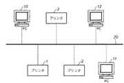
FIG. 1 is a diagram showing a configuration of an embodiment of an image processing system according to the present invention.
同図において、1、2、3はそれぞれレーザビームプリンタ(以降、単に「プリンタ」と称する)であり、10、11、12はパソコン等のCPUを有する情報処理装置(以下、単に「PC」と称する。)であり、20は各機器を接続するネットワークであり、該ネットワークを介して機器間で所定のプロトコルに従って通信が行なわれる。 In the figure,
PC10、11、12は、プリントデータ及び制御コードから成る印刷ジョブを出力し、後述するようにして1から3のいずれかのプリンタが選択され、印刷ジョブに従って印刷が行なわれる。 The
(PCの構成)
図2は、本実施形態のPC10の構成を示す図である。なお、本実施形態におけるPC11及びPC12も同様の構成である。(PC configuration)
FIG. 2 is a diagram illustrating a configuration of the
PC10は、入力手段としてのキーボード306及びマウス307と、表示手段であるディスプレイ・モニタ305とが接続された一つのコンピュータ・システムとして構成されている。PC10は、Windows(登録商標)などの基本ソフト(OS)によって動作しているものとする。 The PC 10 is configured as one computer system to which a
PC10について、本発明に関する部分にのみ注目して機能的に大きく分類すると、アプリケーションソフトウェア301、グラフィック・サブ・システム302、スプールファイル3031および印刷装置との通信インターフェース3032を含むスプーラ303に大別される。 The PC 10 can be broadly classified into the
アプリケーションソフトウェア301は、例えば、ワープロや表計算などのOS上で動作する応用ソフトウェアである。グラフィック・サブ・システム302は、OSの機能の一部であるGraphics Device Interface(以後、GDIと記す)3021と、GDI3021から動的にリンクされるデバイスドライバであるプリンタドライバ3022、バンドスプーラ3023及び積算データ3024によって構成されている。 The
プリンタドライバ3022は、GDI3021からDDI(Device Driver Interface)というインターフェースを介してコールされ、出力対象である印刷装置に応じた処理を描画オブジェクト毎に行う。本実施形態に係るPC10では、DDI関数に渡された情報をプリンタで高速に処理可能な印刷命令データ(ページ記述言語:PDL)形式に変換し、直接スプーラ303に送出する場合と、生成した印刷命令データをバンド単位に分割してバンドスプーラ3023に第1バンドから順に1ページ分保持し、ページの最後にまとめてスプーラ303に送出する場合の二通りの処理が存在する。 The
スプーラ303は、OSが管理しているスプールファイルシステムであり、設定により1ページ単位、またはジョブ単位で印刷データをスプールファイル3031として格納し、I/F3032を介してさらに、ネットワークプロトコルを実現するネットワークインターフェース304を介してプリンタ1〜3に送出する。 The
OSによって、上述した各部の名称や機能的な枠組みが若干異なる場合もあるが、これら名称や枠組みの相違は本発明の本質には影響しない。例えば、本発明でスプーラやスプールファイルと呼ぶモジュールは、別のOSにおいてプリント・キューと呼ばれるモジュールを用いて実現可能である。 Depending on the OS, the names and functional frameworks of the above-described parts may be slightly different. However, differences in these names and frameworks do not affect the essence of the present invention. For example, a module called a spooler or a spool file in the present invention can be realized using a module called a print queue in another OS.
なお一般的に、これらの各機能モジュールを含むPC10は、中央演算処理装置(CPU)、リードオンリーメモリ(ROM)、ランダムアクセスメモリ(RAM)、ハードディスクドライブ(HDD)、各種入出力制御部(I/O)などのハードウェアのもとで、基本ソフト(OS)と呼ばれるソフトウェアがその制御を司り、その基本ソフトの元で、それぞれの応用ソフト、サブ・システム・プロセスが機能モジュールとして動作する。 In general, the PC 10 including these functional modules includes a central processing unit (CPU), a read only memory (ROM), a random access memory (RAM), a hard disk drive (HDD), and various input / output control units (I). The software called basic software (OS) manages the control under hardware such as / O), and under the basic software, the respective application software and sub-system processes operate as function modules.
(プリンタドライバの処理)
図3は、プリンタドライバ3022の処理概要を模式的に説明した図である。ここでは代表して、PC10においてプリンタ1を選択して印刷する場合の処理を説明するが、PC10、11、12のいずれからプリンタ1、2、3のいずれへの印刷であれば本説明と同様である。(Printer driver processing)
FIG. 3 is a diagram schematically illustrating an outline of processing of the
4001は一般的なドキュメント作成アプリケーションを使って作成したドキュメントデータであり、グラフィックス、文字、イメージが含まれているものとする。 Reference numeral 4001 denotes document data created using a general document creation application, and includes graphics, characters, and images.
このようなドキュメントを印刷する際、まずOSにインストールされているプリンタドライバ3022に対して、OSを介して描画命令(4002、4003)が渡される。プリンタドライバ3022は、初期状態は通常のPDLモード系ドライバと同様に、描画命令毎に印刷命令(PDL)を生成し、システムスプーラ303に書き込みを実施する。この際に、プリンタドライバ3022は、コマンド数やコマンドの種類に応じた所定の計算式で計算したデータサイズを積算データ3024として積算していく。積算データ3024は、例えばコンピュータの有するRAMの所定領域に格納される。なお、OSを介してプリンタドライバ3022が受け取る描画命令(DDI関数)は、描画オブジェクトが重ねられているときには下レイヤーから順に出力される仕様になっている。 When printing such a document, first, drawing commands (4002, 4003) are passed to the
1ページ分のデータ全てをシステムスプーラ303に書き込めたときは、スプーラ303にスプールファイル3031として蓄えられた印刷命令(PDL)を、印刷装置100に送出し、積算データ3024をクリアする。一方、積算データ3024の値が、予め定めたデータサイズ、コマンド数等を超えた時は、以下のように処理を切り替える。 When all the data for one page has been written into the
図3の4010は、4002で示される「矩形描画(イメージの背景)4021、イメージ描画命令4022及びイメージの実体4023」までがシステムスプーラ303に格納された様子を示している。本実施形態ではイメージデータ4023をスプーラ303に出力した時点で、積算データ3024が予め定めたデータサイズの閾値を超えたことを契機に処理が切り替えられたものとする。
プリンタドライバ3022は、イメージデータ4023以降の描画命令4003に対する印刷命令を生成し、初期化処理時に例えばRAMの所定領域として確保しておいたバンドスプーラ3023にプリンタ1で処理を行うバンド領域毎に分けて描画順に格納し、管理する(4006)。OSから渡される描画命令403(DDI関数)は、印刷装置の印字方向とは無関係に出力されてくるため、本実施形態のようにページの途中からバンド処理に切り替わった場合にも、第1バンドから第Nバンドまでページ内のすべてのバンドに対する格納処理が行われる。 The
格納処理は、プリンタドライバ内のDDI関数がコールされる度に行う。バンド領域内に格納領域に格納できなくなった時は、新たにRAMの領域を確保することで対処する。第1バンドから第Nバンドまでの1ページ分の残りの描画データ格納が終了したら、印刷装置で処理するバンド順にデータをシステムスプーラ303に書き出す(4009)。 The storing process is performed every time the DDI function in the printer driver is called. When it becomes impossible to store in the storage area in the band area, a new RAM area is secured. After storing the remaining drawing data for one page from the first band to the Nth band, the data is written to the
各バンドデータの先頭には、以降に送出するバンド情報4011をつけることで、プリンタ1側で印刷データがページ単位からバンド単位に移行したことを認識可能とする。1ページ分の印刷データをシステムスプーラ303にスプールしたら、プリンタ1に送出する(4012)。 By attaching
(プリンタの構成)
図4は、本実施形態のプリンタ1の構成を示す図である。本実施形態においては、プリンタ2及びプリンタ3も同様の構成である。(Printer configuration)
FIG. 4 is a diagram illustrating a configuration of the
311は、イメージデータ(2値または多値データ)に基づいて、周知の電子写真プロセスによって感光ドラム上に潜像を形成し、用紙に転写して定着し印字を行うエンジン部であり、310は、エンジン部311に接続され、PC10、11、12から送られるコードデータ(ESCコード、各種PDL等)を受け、このコードデータに基づいてドットデータからなるページ情報を生成しエンジン部311に対して所定のインターフェース手段によってイメージデータを送信するコントローラ部であり、312は、ユーザ(操作者)とのインターフェースを行なうパネル部312であり、不図示のタッチセンサを有する液晶パネルと、キーボードで構成される。ユーザは、パネル部312を操作することによって、プリンタ1に所定の動作を指示することができる。
コントローラ部310に関して説明する。コントローラ部310は、ネットワーク20に対する接続手段であるインターフェース(I/Fとも表記する)部3101と、受信データ等を一時的に保持管理するための受信バッファ3103、送信データ等を一時的に保持管理するための送信バッファ3104、印刷データの解析を司るコマンド解析部3107、印刷制御処理実行部3109、描画処理実行部3105、ページメモリ3106より構成されている。 The
インターフェース部3101は、ネットワーク20を介してPC10〜12との印刷データの送受信を行う通信手段である。 The
インターフェース部3101を通して受信した印刷データは、そのデータを一時的に保持する記憶手段である受信バッファ3103に逐次蓄積され、必要に応じてコマンド解析部3107または描画処理実行部3105によって読み出され処理される。コマンド解析部3107は、印刷命令体系や印刷ジョブ制御言語に準じた制御プログラムにより構成されており、文字印字、図形、イメージなどの描画に関する印刷データの解析結果は、描画処理実行部3105に指示を与えて処理し、給紙選択やリセット命令などの描画以外のコマンドは、印刷制御処理実行部3109に指示を出し処理する。 The print data received through the
描画処理実行部3105は、文字やイメージの各描画オブジェクトをページメモリ3106内のバンドメモリに逐次展開して行く、Y(イエロー)M(マゼンタ)C(シアン)K(ブラック)の4色のレンダラである。 A rendering
例えば、カラーLBPエンジンに対しては、MCYKの順番でデバイス依存ビットマップデータを送出する必要があるが、標準状態では、そのために必要なメモリをすべて確保するわけではなく、1プレーン(1,2又は4bit/pixel)の数分の1のメモリ領域がバンドメモリ領域としてページメモリ3106内に確保される。そして、バンドメモリ領域を繰り返し用い、プリンタエンジン3110の処理に同期して描画処理するように構成されている。 For example, for the color LBP engine, it is necessary to send device-dependent bitmap data in the order of MCYK. However, in the standard state, not all the memory necessary for this is secured, and one plane (1, 2 Alternatively, a memory area of a fraction of 4 bits / pixel) is secured in the
通常はこのように、描画処理実行部3105による展開処理をプリンタエンジン3110へのビデオ信号のシッピング処理が追いかけるバンディング制御によってページメモリ3106は管理されているが、十分なメモリがある場合は1ページ分が展開可能なメモリ領域を確保しても良い。 Normally, the
なお、コントローラ部310は、中央演算処理装置(CPU)、リードオンリーメモリ(ROM)、ランダムアクセスメモリ(RAM)などを用いたコンピュータ・システムによって構成されている。また、コントローラ部310内の各部の処理は、マルチタスクモニタ(リアルタイムOS)のもとでタイムシェアリングで処理される構成であっても良いし、機能毎に専用のコントローラ・ハードウェアを用意して独立して処理される構成であってもかまわない。 The
出力制御部3108は、バンドメモリ(ページメモリ)3106の内容をビデオ信号に変換処理し、プリンタエンジン3110へ転送する。 The
(グリッドコンピューティングに関する構成)
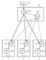
図5は、本実施形態においてグリッドコンピューティングのフレームワークを活用する構成を説明するための図である。同図は、グリッドフレームワークを画像処理装置のPDL処理に適用した場合の構成を示している。(Configuration related to grid computing)
FIG. 5 is a diagram for explaining a configuration that utilizes the framework of grid computing in the present embodiment. This figure shows a configuration when the grid framework is applied to the PDL processing of the image processing apparatus.
本実施形態においてTM400及びDJS401は、PC12内に設けられており、本実施形態の画像処理システム全体のリソースを管理するものとする。またブローカ410、411及び412と、RM420、421及び422との組は、各々プリンタ1、2、3に設けられている。 In the present embodiment, the
なお、本図の各部の動作については、後述のフローチャートに関連して説明する。 The operation of each part in this figure will be described in relation to a flowchart described later.
(履歴情報)
図6は、本実施形態において表示する履歴情報の例を示す図である。(History information)
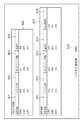
FIG. 6 is a diagram illustrating an example of history information displayed in the present embodiment.
本実施形態では、DJS401が、RM420、421、422によって通知されるリソース(プリンタ)の状態変化を、履歴として蓄積管理し、グリッドコンピューティングにおけるスケジューリングの際の参照情報とする。また、ユーザがこの履歴情報を参照することが可能なように、ディスプレイ・モニタ305もしくは、プリンタ1,2,3からの印刷出力が可能である。 In this embodiment, the
図6において、500は、表示された時刻までの所定の時間(1時間)における履歴情報である時刻実績を表し、510は、例えば1ヶ月などの所定の履歴保存期間に渡る履歴情報である期間実績を表している。 In FIG. 6, 500 represents a time record that is history information in a predetermined time (one hour) until the displayed time, and 510 is a period that is history information over a predetermined history storage period such as one month, for example. Represents achievements.
501及び511は「装置名称」であって、システムを構成するプリンタ1〜3をそれぞれ示す名称がこの欄に表示される。502及び512は「アイドル率」であって、装置が非稼動状態である割合を示している。503及び513は「平均アイドル時間」であって、装置が1時間のうち非稼動状態である平均時間を示している。504及び514は「達成率」であって、装置がTMから受信したジョブを中止することなく完遂した回数をジョブを受信した回数で除した割合を示している。
また、520の「システム活用率」は、本実施形態のシステム全体のリソースの使用されている比率として、全装置(プリンタ1〜3)の「達成率」の平均を示している。 A “system utilization rate” of 520 indicates an average of “achievement rates” of all apparatuses (
(履歴情報の管理)
図7は、本実施形態において履歴情報を管理する形態を説明するための図である。(Management of history information)
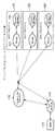
FIG. 7 is a diagram for explaining a mode of managing history information in the present embodiment.
図6に示したような履歴情報は、リソースリスト601にリンクされたリソース管理テーブル602に格納される。リソースリスト601とリソース管理テーブル602は、いずれもDJS402によって管理され、実体(データ)はPC12の所定の不揮発メモリ(HDDを含む)に格納される。 The history information as shown in FIG. 6 is stored in the resource management table 602 linked to the
リソース管理テーブル602は、管理情報、状態情報、履歴の3つの部分を含んでおり、図6に示した例との対応を説明すると、デバイス名称は装置名称501及び511、時刻実績は500、期間実績は510に、システム活用率は520にそれぞれ対応する。 The resource management table 602 includes three parts: management information, status information, and history. The correspondence with the example shown in FIG. 6 will be described. The device names are the
なお、時刻実績は、後述するように、装置毎に所定の間隔毎あるいは何らかの状態変化が生じた度に更新される。 As will be described later, the time record is updated every predetermined interval or whenever some state change occurs for each device.
(履歴情報の更新処理)
図8は、本実施形態における履歴情報の更新に関する処理を説明するためのフローチャートである。(History information update process)
FIG. 8 is a flowchart for explaining processing relating to update of history information in the present embodiment.
例えば、PC10からプリンタ1に対して印刷ジョブ(プリント処理依頼)が投入されると(ステップS101)、TM400、DJS401によりブローカ410〜412の1つもしくは複数に対するサブジョブに分割される。分割単位は前述のようなバンド単位、あるいはページ単位、ジョブ単位のいずれかがTM400によって選択される。またDJS401は、上記の時刻実績500に基づいて、TM400の指示に応じてサブジョブへの分割を行う(ステップS102)。 For example, when a print job (print processing request) is input from the
各サブジョブは、指定されたブローカ410〜412に送信され、RM420〜422を経由してプリンタ1〜3のそれぞれで処理される。例えば、ブローカ411にサブジョブが送信されると、RM421は、リソースの情報(プリンタ2の空き状況)をブローカ411に通知し、ブローカ411からの指示によりリソース(プリンタ2)にサブジョブを投入する(ステップS103)。 Each sub-job is transmitted to the designated
更にRM420〜422は、定期的に各リソース(プリンタ)の状態を吸い上げ、異常があれば対応するブローカへ通知する。異常状態とは、故障の発生等に加えグリッドコンピューティングによるジョブ以外の通常の経路で投入されるジョブ、例えばPCからプリンタを指定して投入されたジョブを含むものであって、サブジョブ処理の継続ができなくなる場合を含んでいる。 Further, the
各RMから異常状態がDJS401に通知されると(ステップS104)、DJS401は、その内容と発生時刻を履歴として保存して履歴を更新し(ステップS110)、更新された時刻実績に基づいて当該サブジョブの処理対象のリソース(プリンタ)を再度設定する(ステップS102)。 When the abnormal state is notified from each RM to the DJS 401 (step S104), the
ステップS104で異常状態の通知がなく、サブジョブを割り当てられた全てのRMから完了通知を受けると(ステップS105)、DJS402とTM400は指定されたリソース(プリンタ1)において、処理済みのサブジョブを結合して処理済みジョブを生成するよう指示し(ステップS106)、プリンタ1において印刷を実行することで(ステップS107)処理が終了する。 If there is no notification of an abnormal state in step S104 and completion notifications are received from all the RMs to which the sub job is assigned (step S105), DJS 402 and
以上説明したように本実施形態によれば、複数の画像処理装置と複数のコンピュータ装置を含み、グリッドコンピューティング技術を用いて処理を分散する画像処理システムにおいて、画像処理装置毎の処理実績を履歴情報として保存し、直近の時刻履歴に基づいてジョブの達成率が高いクライアントに対して優先的にジョブを割り当てることが可能となる。 As described above, according to the present embodiment, in an image processing system that includes a plurality of image processing devices and a plurality of computer devices and distributes processing using grid computing technology, the processing results for each image processing device are recorded as a history. It is possible to preferentially assign a job to a client having a high job achievement rate based on the latest time history.
更に、所定の期間に渡るグリッドコンピューティングの実績を示す期間実績を表示あるいは印刷することができるので、ユーザにグリッドコンピューティングによる処理実績を定量的に示すことができ、システム導入による効果や対投資効果等を明確化するための情報として利用できる。 Furthermore, since the period results indicating the results of grid computing over a predetermined period can be displayed or printed, the results of processing by grid computing can be quantitatively shown to the user, and the effects of system introduction and investment It can be used as information for clarifying effects.
<実施形態の変形例>
上記の実施形態ではPCとプリンタをそれぞれ複数含むシステムを例として説明したが、画像処理装置としてMFPが含まれていてもよく、複数のMFPやプリンタが接続されているネットワーク環境においても同様に適用される。<Modification of Embodiment>
In the above embodiment, a system including a plurality of PCs and printers has been described as an example. However, an MFP may be included as an image processing apparatus, and the same applies to a network environment in which a plurality of MFPs and printers are connected. Is done.
また、実施形態では、PCとプリンタとをそれぞれ3台含むシステムを例として説明したが、システムに含まれるPCや画像処理装置の台数についても特に制限はない。 In the embodiment, a system including three PCs and three printers has been described as an example. However, the number of PCs and image processing apparatuses included in the system is not particularly limited.
更に、実施形態のシステムでは、TM400及びDJS401がPC12に設けられているものとして説明したが、TM400及びDJS401の設けられる機器はシステム内のどの機器でもよく、PC10〜12及びプリンタ1〜3のいずれに設けられていてもよい。 Further, in the system according to the embodiment, the
加えて、実施形態のシステムにおいては、リソースリスト601とリソース管理テーブル602はいずれもDJS402によって管理され、実体はPC12の所定の不揮発メモリ(HDDを含む)に格納されると説明したが、実体が格納される位置はシステム内のアクセス可能な不揮発メモリであればどこでもよき、特に制限はない。 In addition, in the system of the embodiment, it has been described that both the
更にまた、上記の履歴情報の項目に加えて、「システム活用率」に対価係数を掛けることによって得られる値を、システム活用効果として定量的な投資効果を簡易的に表す値として含めてもよく、また、この値を含む履歴情報を、ディスプレイ・モニタ305への表示もしくは、プリンタ1〜3からの印刷によって自動的に表示あるいは印刷させるようにしてもよい。 Furthermore, in addition to the above history information item, a value obtained by multiplying the “system utilization rate” by a consideration coefficient may be included as a value that simply represents a quantitative investment effect as a system utilization effect. The history information including this value may be automatically displayed or printed by displaying on the display monitor 305 or printing from the
<他の実施形態>
本発明は、複数の機器から構成されるグリッドコンピューティングシステム(グリッド網)に適用しても良いし、また、グリッド網を構成する一つの機器に適用しても良い。<Other embodiments>
The present invention may be applied to a grid computing system (grid network) constituted by a plurality of devices, or may be applied to one device constituting the grid network.
また、上記の実施形態では、印刷ジョブをグリッドコンピューティングによって画像処理装置に割り当てる例について説明したが、印刷ジョブ以外のジョブ、例えば画像処理のジョブを画像処理装置に割り当てるようにしてもよく、同様の効果が得られる。 In the above embodiment, an example in which a print job is assigned to an image processing apparatus by grid computing has been described. However, a job other than a print job, for example, an image processing job may be assigned to an image processing apparatus. The effect is obtained.
なお、本発明は、前述した実施形態の機能を実現するソフトウェアのプログラム(本実施形態では図8に示すフローチャートに対応したプログラム)を、システム或いは装置に直接或いは遠隔から供給し、そのシステム或いは装置のコンピュータが該供給されたプログラムコードを読み出して実行することによっても達成される場合を含む。その場合、プログラムの機能を有していれば、形態は、プログラムである必要はない。 In the present invention, a software program (in this embodiment, a program corresponding to the flowchart shown in FIG. 8) that realizes the functions of the above-described embodiment is directly or remotely supplied to the system or apparatus. The computer can read out and execute the supplied program code. In that case, as long as it has the function of a program, the form does not need to be a program.
従って、本発明の機能処理をコンピュータで実現するために、該コンピュータにインストールされるプログラムコード自体も本発明を実現するものである。つまり、本発明のクレームでは、本発明の機能処理を実現するためのコンピュータプログラム自体も含まれる。 Accordingly, since the functions of the present invention are implemented by computer, the program code installed in the computer also implements the present invention. That is, the claims of the present invention include the computer program itself for realizing the functional processing of the present invention.
その場合、プログラムの機能を有していれば、オブジェクトコード、インタプリタにより実行されるプログラム、OSに供給するスクリプトデータ等、プログラムの形態を問わない。 In this case, the program may be in any form as long as it has a program function, such as an object code, a program executed by an interpreter, or script data supplied to the OS.
プログラムを供給するための記録媒体としては、例えば、フレキシブルディスク、ハードディスク、光ディスク、光磁気ディスク、MO、CD−ROM、CD−R、CD−RW、磁気テープ、不揮発性のメモリカード、ROM、DVD(DVD−ROM,DVD−R)などがある。 As a recording medium for supplying the program, for example, flexible disk, hard disk, optical disk, magneto-optical disk, MO, CD-ROM, CD-R, CD-RW, magnetic tape, nonvolatile memory card, ROM, DVD (DVD-ROM, DVD-R).
その他、プログラムの供給方法としては、クライアントコンピュータのブラウザを用いてインターネットのホームページに接続し、該ホームページから本発明のコンピュータプログラムそのもの、もしくは圧縮され自動インストール機能を含むファイルをハードディスク等の記録媒体にダウンロードすることによっても供給できる。また、本発明のプログラムを構成するプログラムコードを複数のファイルに分割し、それぞれのファイルを異なるホームページからダウンロードすることによっても実現可能である。つまり、本発明の機能処理をコンピュータで実現するためのプログラムファイルを複数のユーザに対してダウンロードさせるWWWサーバも、本発明の範囲に含まれるものである。 As another program supply method, a client computer browser is used to connect to an Internet homepage, and the computer program of the present invention itself or a compressed file including an automatic installation function is downloaded from the homepage to a recording medium such as a hard disk. Can also be supplied. It can also be realized by dividing the program code constituting the program of the present invention into a plurality of files and downloading each file from a different homepage. That is, a WWW server that allows a plurality of users to download a program file for realizing the functional processing of the present invention on a computer is also included in the scope of the present invention.
また、本発明のプログラムを暗号化してCD−ROM等の記憶媒体に格納してユーザに配布し、所定の条件をクリアしたユーザに対し、インターネットを介してホームページから暗号化を解く鍵情報をダウンロードさせ、その鍵情報を使用することにより暗号化されたプログラムを実行してコンピュータにインストールさせて実現することも可能である。 In addition, the program of the present invention is encrypted, stored in a storage medium such as a CD-ROM, distributed to users, and key information for decryption is downloaded from a homepage via the Internet to users who have cleared predetermined conditions. It is also possible to execute the encrypted program by using the key information and install the program on a computer.
また、コンピュータが、読み出したプログラムを実行することによって、前述した実施形態の機能が実現される他、そのプログラムの指示に基づき、コンピュータ上で稼動しているOSなどが、実際の処理の一部または全部を行ない、その処理によっても前述した実施形態の機能が実現され得る。 In addition to the functions of the above-described embodiments being realized by the computer executing the read program, the OS running on the computer based on an instruction of the program is a part of the actual processing. Alternatively, the functions of the above-described embodiment can be realized by performing all of them and performing the processing.
さらに、記録媒体から読み出されたプログラムが、コンピュータに挿入された機能拡張ボードやコンピュータに接続された機能拡張ユニットに備わるメモリに書き込まれた後、そのプログラムの指示に基づき、その機能拡張ボードや機能拡張ユニットに備わるCPUなどが実際の処理の一部または全部を行ない、その処理によっても前述した実施形態の機能が実現される。 Furthermore, after the program read from the recording medium is written to a memory provided in a function expansion board inserted into the computer or a function expansion unit connected to the computer, the function expansion board or The CPU or the like provided in the function expansion unit performs part or all of the actual processing, and the functions of the above-described embodiments are also realized by the processing.
1〜3 プリンタ
10〜12 PC
20 ネットワーク
500 時刻実績
501、511 装置名
502、512 アイドル率
503、513 平均アイドル時間
504、514 達成率
510 期間実績
515 グリッド活用率
520 システム活用率1-3 Printer 10-12 PC
20
Claims (5)
Translated fromJapanese前記複数の画像処理装置がジョブを分割したサブジョブを処理中に、他のジョブに対して処理の実行が指示されずに、該サブジョブの処理が完遂した割合を示す達成率を格納する格納手段と、
前記サブジョブを分配する画像処理装置を、前記格納手段に格納された達成率が高い画像処理装置から優先的に選択する選択手段と、
前記サブジョブを前記選択手段で選択された画像処理装置に分配するタスク管理手段と、
前記タスク管理手段によって分配されたサブジョブの処理を実行している画像処理装置において、他のジョブに対して処理の実行が指示され、該画像処理装置が該サブジョブに対する処理を中断し、該他のジョブに対して処理が実行されたという通知を受けると、前記格納手段に格納された達成率が更新され、前記中断されたサブジョブを分配する画像処理装置を、該更新された達成率が高い画像処理装置から優先的に再選択する再選択手段と、
を備えることを特徴とする情報処理装置。An information processing apparatus connected to a plurality of image processing apparatuses,
Storage meansfor storing an achievement rate indicating a rate at which the processing of the sub job is completed without instructing execution of processing for another job while the plurality of image processing apparatuses are processing the sub job divided into jobs. ,
Selection means for pre-image processing apparatus for dispensing ahexaBujobu, preferentially selected from the storage means the stored achieved rate is higher image processing apparatus,
Task management means for distributing the sub-job to the image processing apparatusselected by theselection means ;
In the image processing apparatus that is executing processing of the sub job distributed by the task management unit, execution of processing is instructed to another job, the image processing apparatus interrupts processing for the sub job, and the other job Upon receiving a notification that processing has been executed for the job, the achievement rate stored in the storage means is updated, and the image processing apparatus that distributes the suspended sub-job is updated with the image with the high achievement rate. Reselection means for reselecting preferentially from the processing device;
An information processing apparatus comprising:
前記複数の画像処理装置がジョブを分割したサブジョブを処理中に、他のジョブに対して処理の実行が指示されずに、該サブジョブの処理が完遂した割合を示す達成率を格納部に格納する格納工程と、 While the plurality of image processing apparatuses are processing a sub job obtained by dividing a job, an execution rate indicating a rate at which the processing of the sub job is completed is stored in the storage unit without instructing other jobs to execute the processing. Storage process;
前記サブジョブを分配する画像処理装置を、前記格納部に格納された達成率が高い画像処理装置から優先的に選択する選択工程と、 A selection step of preferentially selecting an image processing apparatus that distributes the sub-job from image processing apparatuses having a high achievement rate stored in the storage unit;
前記サブジョブを前記選択工程で選択された画像処理装置に分配するタスク管理工程と、 A task management step of distributing the sub-job to the image processing apparatus selected in the selection step;
前記タスク管理工程によって分配されたサブジョブの処理を実行している画像処理装置において、他のジョブに対して処理の実行が指示され、該画像処理装置が該サブジョブに対する処理を中断し、該他のジョブに対して処理が実行されたという通知を受けると、前記格納部に格納された達成率が更新され、前記中断されたサブジョブを分配する画像処理装置を、該更新された達成率が高い画像処理装置から優先的に再選択する再選択工程と、 In the image processing apparatus executing the processing of the sub job distributed by the task management process, execution of processing is instructed to another job, the image processing apparatus interrupts the processing for the sub job, and the other job Upon receiving a notification that processing has been executed for the job, the achievement rate stored in the storage unit is updated, and the image processing apparatus that distributes the interrupted sub-job is updated with the image with the high achievement rate. A reselection step for preselection from the processing device preferentially;
を備えることを特徴とする情報処理装置の制御方法。An information processing apparatus control method comprising:
Priority Applications (1)
| Application Number | Priority Date | Filing Date | Title |
|---|---|---|---|
| JP2004171764AJP4412718B2 (en) | 2004-06-09 | 2004-06-09 | Information processing apparatus and control method thereof |
Applications Claiming Priority (1)
| Application Number | Priority Date | Filing Date | Title |
|---|---|---|---|
| JP2004171764AJP4412718B2 (en) | 2004-06-09 | 2004-06-09 | Information processing apparatus and control method thereof |
Publications (3)
| Publication Number | Publication Date |
|---|---|
| JP2005352693A JP2005352693A (en) | 2005-12-22 |
| JP2005352693A5 JP2005352693A5 (en) | 2007-07-26 |
| JP4412718B2true JP4412718B2 (en) | 2010-02-10 |
Family
ID=35587144
Family Applications (1)
| Application Number | Title | Priority Date | Filing Date |
|---|---|---|---|
| JP2004171764AExpired - Fee RelatedJP4412718B2 (en) | 2004-06-09 | 2004-06-09 | Information processing apparatus and control method thereof |
Country Status (1)
| Country | Link |
|---|---|
| JP (1) | JP4412718B2 (en) |
Families Citing this family (3)
| Publication number | Priority date | Publication date | Assignee | Title |
|---|---|---|---|---|
| JP4725964B2 (en)* | 2006-01-30 | 2011-07-13 | 株式会社リコー | Distributed processing system, distributed processing method, job arbiter used for distributed processing, and program |
| JP2008071294A (en)* | 2006-09-15 | 2008-03-27 | Korea Univ Industrial & Academic Collaboration Foundation | Method for adapted group scheduling by mobile agent in peer-to-peer grid computing environment |
| JP5598229B2 (en) | 2010-10-01 | 2014-10-01 | 富士ゼロックス株式会社 | Job distributed processing system, information processing apparatus, and program |
- 2004
- 2004-06-09JPJP2004171764Apatent/JP4412718B2/ennot_activeExpired - Fee Related
Also Published As
| Publication number | Publication date |
|---|---|
| JP2005352693A (en) | 2005-12-22 |
Similar Documents
| Publication | Publication Date | Title |
|---|---|---|
| US8045202B2 (en) | Information processing apparatus and print device control method | |
| US7936468B2 (en) | Systems and methods for load balancing toner use in a printer pool | |
| JP3977356B2 (en) | Information processing apparatus and control method thereof | |
| US8472043B2 (en) | Information processing apparatus and its control method for managing distributed processing | |
| US7707326B2 (en) | System for setting print end notification either when data transmission ends or when printing ends based on print check ability of printing devices | |
| JP4944369B2 (en) | Information processing apparatus and control method thereof | |
| US20060209343A1 (en) | Information processing apparatus, distributed printing method, and storage medium | |
| JP2005352697A (en) | Computer system and job assignment method in the system | |
| JP4208769B2 (en) | Information processing apparatus, control method thereof, and information processing method | |
| US7835022B2 (en) | Grid computing system, and job allocation method in grid computing system | |
| KR100757154B1 (en) | Information processing apparatus and its control method | |
| JP2002182879A (en) | Print control apparatus and method and print system | |
| US20060139686A1 (en) | Information processing apparatus, image forming apparatus, recording medium having recorded operation control program, and image forming system | |
| JP5099594B2 (en) | Image processing apparatus, image processing system, and image processing program | |
| JP5857594B2 (en) | Distributed printing system and printing apparatus | |
| JP4412718B2 (en) | Information processing apparatus and control method thereof | |
| JP4095581B2 (en) | Information processing apparatus and control method thereof | |
| JPH11143656A (en) | Printing system, data processing method of printing system, and storage medium storing computer readable program | |
| JP3994984B2 (en) | Print support module, recording medium, and print job issuing method | |
| JP2001109599A (en) | Information processing apparatus, data processing method, and storage medium | |
| JP2007140952A (en) | Distributed processing system and processing method thereof | |
| JP2006155497A (en) | Image forming system | |
| JP2006163870A (en) | Image forming apparatus | |
| JP2006031439A (en) | Image recording system | |
| JP4143598B2 (en) | Management method in information processing apparatus, information processing apparatus, program, and storage medium |
Legal Events
| Date | Code | Title | Description |
|---|---|---|---|
| A521 | Written amendment | Free format text:JAPANESE INTERMEDIATE CODE: A523 Effective date:20070611 | |
| A621 | Written request for application examination | Free format text:JAPANESE INTERMEDIATE CODE: A621 Effective date:20070611 | |
| RD03 | Notification of appointment of power of attorney | Free format text:JAPANESE INTERMEDIATE CODE: A7423 Effective date:20070611 | |
| A977 | Report on retrieval | Free format text:JAPANESE INTERMEDIATE CODE: A971007 Effective date:20090206 | |
| A131 | Notification of reasons for refusal | Free format text:JAPANESE INTERMEDIATE CODE: A131 Effective date:20090803 | |
| A521 | Written amendment | Free format text:JAPANESE INTERMEDIATE CODE: A523 Effective date:20091002 | |
| TRDD | Decision of grant or rejection written | ||
| A01 | Written decision to grant a patent or to grant a registration (utility model) | Free format text:JAPANESE INTERMEDIATE CODE: A01 Effective date:20091113 | |
| A01 | Written decision to grant a patent or to grant a registration (utility model) | Free format text:JAPANESE INTERMEDIATE CODE: A01 | |
| A61 | First payment of annual fees (during grant procedure) | Free format text:JAPANESE INTERMEDIATE CODE: A61 Effective date:20091116 | |
| FPAY | Renewal fee payment (event date is renewal date of database) | Free format text:PAYMENT UNTIL: 20121127 Year of fee payment:3 | |
| R150 | Certificate of patent or registration of utility model | Free format text:JAPANESE INTERMEDIATE CODE: R150 | |
| FPAY | Renewal fee payment (event date is renewal date of database) | Free format text:PAYMENT UNTIL: 20131127 Year of fee payment:4 | |
| LAPS | Cancellation because of no payment of annual fees |