JP4412464B2 - Image processing apparatus and image processing method - Google Patents
Image processing apparatus and image processing methodDownload PDFInfo
- Publication number
- JP4412464B2 JP4412464B2JP2003420072AJP2003420072AJP4412464B2JP 4412464 B2JP4412464 B2JP 4412464B2JP 2003420072 AJP2003420072 AJP 2003420072AJP 2003420072 AJP2003420072 AJP 2003420072AJP 4412464 B2JP4412464 B2JP 4412464B2
- Authority
- JP
- Japan
- Prior art keywords
- processing
- translucent
- drawing command
- intermediate code
- image processing
- Prior art date
- Legal status (The legal status is an assumption and is not a legal conclusion. Google has not performed a legal analysis and makes no representation as to the accuracy of the status listed.)
- Expired - Fee Related
Links
- 238000003672processing methodMethods0.000titleclaims9
- 238000000034methodMethods0.000claimsdescription35
- 238000004458analytical methodMethods0.000claimsdescription11
- 238000000354decomposition reactionMethods0.000description15
- 238000010586diagramMethods0.000description6
- 238000004364calculation methodMethods0.000description1
- 238000007796conventional methodMethods0.000description1
- 230000007547defectEffects0.000description1
- 230000000694effectsEffects0.000description1
- 238000000605extractionMethods0.000description1
- 238000004519manufacturing processMethods0.000description1
Images


Landscapes
- Image Processing (AREA)
- Image Generation (AREA)
- Editing Of Facsimile Originals (AREA)
Description
Translated fromJapanese本発明は、半透明処理を行う画像処理技術に関するものである。 The present invention relates to an image processing technique for performing translucent processing.
描画コマンドに従って図形を描画してゆくとき、ある図形を描画した上に他の図形を描画するとき、簡単には上書きしている。この場合、上書きされた部分には先に描画された図形の片鱗は残らない。そのため、後の図形を描画する際に、それまでにどのような図形が描画されたかを、それほど考慮しなくても描画処理を進めることができる。 When drawing a figure according to a drawing command, when drawing one figure and drawing another figure, it is easily overwritten. In this case, the scale of the previously drawn figure does not remain in the overwritten portion. Therefore, when drawing a subsequent figure, the drawing process can be performed without considering so much what figure has been drawn so far.
このような上書きによる描画のほか、既に描画された図形と上から描画する図形の両方をある程度ずつ残しながら描画する半透明処理も行われている。このような半透明処理を行うためには、新たに描画する図形と重なる領域について、それまでに描画された内容を反映しなければならない。そのために、図形間の重なり部分を抽出する必要が生じる。 In addition to such overwriting, translucent processing is also performed in which drawing is performed while leaving both the already drawn figure and the figure drawn from above to some extent. In order to perform such a translucent process, it is necessary to reflect the contents that have been drawn so far in the area that overlaps the newly drawn figure. Therefore, it is necessary to extract an overlapping portion between figures.
従来の半透明処理として、例えば画素毎に重なりを判定し、重なっていると判定された画素について半透明処理を行う方法がある。しかしこの方法の場合、画素毎の処理を多数の描画図形ごとに行うことになるため、膨大な処理量を要し、非常に時間がかかる処理である。また、ビットマップに展開しながら処理を行うため、多大なメモリ量を必要とするという問題もある。 As a conventional translucent process, for example, there is a method of determining an overlap for each pixel and performing a translucent process on pixels determined to be overlapped. However, in the case of this method, the processing for each pixel is performed for each of a large number of drawing figures, which requires a huge amount of processing and is very time consuming. Another problem is that a large amount of memory is required because processing is performed while expanding into a bitmap.
別の従来技術として、例えば特許文献1に記載されているように、描画コマンドから平面上マップを生成する方法も知られている。この方法は、描画コマンドから、描画する図形を他の図形との重なりに応じて分割し、分割された他の図形と重なっている図形について半透明処理を施すものである。この方法では、分割された図形について、実際の半透明処理時には領域の判定を行う必要が無くなるため、全体の計算量を減らすことができる。また、描画コマンドのレベルで処理を行うため、必要とするメモリ量も少なくてすむ。 As another conventional technique, a method for generating a map on a plane from a drawing command is also known as described in, for example,
しかし、描画コマンドにより描画する図形が他の図形と重なっている部分を分割する際の処理は、例えば描画する図形が曲線を含むような場合には非常に複雑な処理が必要であり、やはり処理に時間がかかってしまう。また、図形を分割してしまうために、分離した図形を実際に描画するときに誤差が生じ、1つの図形として描画したのに隙間が空いてしまうなどの不具合を生じる原因となっていた。 However, the process for dividing the part where the figure to be drawn by the drawing command overlaps with another figure is very complicated when the figure to be drawn contains a curve, for example. Takes time. In addition, since the figure is divided, an error occurs when the separated figure is actually drawn, and this causes a problem such as a gap being formed even though the figure is drawn as one figure.
本発明は、上述した事情に鑑みてなされたもので、半透明処理における処理速度を向上させるとともに、必要とするメモリ量を削減し、さらに描画された画像に不具合の生じない画像処理装置および画像処理情報を提供することを目的とするものである。 The present invention has been made in view of the above-described circumstances, and improves the processing speed in translucent processing, reduces the amount of memory required, and further prevents an image processing apparatus and image from causing a defect in a drawn image. The purpose is to provide processing information.
本発明は、描画コマンドを解析して中間コードをバンド単位に生成し、記描画コマンドに半透明処理が指定されていないバンドについては中間コードのまま出力するが、半透明処理が指定されているバンドについては中間コードをスキャンラインの集合あるいは台形もしくは矩形の集合に分解する。そして、例えばスキャンラインに分解した場合、描画コマンドにおいて半透明処理が指定されているときには、スキャンラインの集合から同一ラインに存在する各描画図形のスキャンラインの重なりを判定し、重なり部分について半透明処理を行う。また、例えば台形もしくは矩形の集合に分解した場合も同様であり、描画コマンドにおいて半透明処理が指定されているときには、台形もしくは矩形の集合から所定の方向に位置する複数の台形もしくは矩形について重なりを判定して、重なり部分について半透明処理を行う。 The present invention analyzes the drawing command and generates an intermediate code for each band, and outputs a band for which the translucent processing is not specified in the drawing command as it is, but the translucent processing is specified. For bands, the intermediate code is decomposed into a set of scan lines or a set of trapezoids or rectangles. For example, when the image is decomposed into scan lines and the translucent process is specified in the drawing command, the overlap of the scan lines of the respective drawing figures existing on the same line is determined from the set of scan lines, and the overlapped portion is translucent. Process. The same applies to, for example, a case where a trapezoid or a set of rectangles is decomposed. Judgment and semi-transparency processing are performed on the overlapping portion.
このようなスキャンライン単位や台形もしくは矩形単位の重なりの判定および半透明処理は、非常に単純な処理で実行でき、処理の高速化を実現することができる。また、このような単位での処理はそれほどメモリ量を必要とせず、従来に比べてメモリ量を削減することができる。さらに、このような単位での処理は、実際の描画処理時と処理単位を共通化することができるため、誤差などによる不具合も生じない。 Such determination of overlap in scan line units, trapezoidal or rectangular units, and translucent processing can be executed by very simple processing, and high-speed processing can be realized. Further, the processing in such a unit does not require a large amount of memory, and the amount of memory can be reduced as compared with the conventional case. Furthermore, since processing in such a unit can share the processing unit with the actual drawing processing, there is no problem due to errors or the like.
また、スキャンラインや台形もしくは矩形の重なり判定の処理をさらに高速化するため、描画コマンドの解析時に、描画コマンドで描画される図形の外接矩形情報を生成し、前記外接矩形情報を参照して重なり判定を行うように構成することもできる。 In addition, in order to further speed up the process of determining overlap of scan lines, trapezoids, or rectangles, at the time of drawing command analysis, circumscribing rectangle information of a figure drawn by the drawing command is generated, and overlapping is performed by referring to the circumscribing rectangle information. It can also be configured to make a determination.
このようなスキャンラインの集合や台形もしくは矩形の集合に対して半透明処理を行った後は、それらのスキャンラインの集合や台形もしくは矩形の集合から平面上マップを再構成することができる。これによって、平面上マップを利用して描画処理を行っているシステムに対しても本発明を適用することが可能となる。 After semi-transparent processing is performed on such a set of scan lines or a trapezoidal or rectangular set, a map on the plane can be reconstructed from the set of scanlines or the trapezoidal or rectangular set. Accordingly, the present invention can be applied to a system that performs drawing processing using a map on a plane.
本発明によれば、図形コマンドあるいは図形コマンドから生成した中間コードから、スキャンラインの集合あるいは台形もしくは矩形の集合に分解して、重なり判定の処理や半透明処理を行う。これによって、単純な処理で実行できるので、処理を高速化することができる。また、このような単位での処理はそれほどメモリ量を必要とせず、従来に比べてメモリ量を削減することができる。さらに、このような単位での処理は、実際の描画処理時と処理単位を共通化することができるため、誤差などによる不具合も生じず、良好な画像を得ることができるという効果がある。 According to the present invention, a graphics command or an intermediate code generated from the graphics command is decomposed into a set of scan lines or a set of trapezoids or rectangles to perform overlap determination processing and translucent processing. As a result, the process can be executed with a simple process, and the process can be speeded up. Further, the processing in such a unit does not require a large amount of memory, and the amount of memory can be reduced as compared with the conventional case. Further, the processing in such a unit can share the processing unit with the actual drawing process, so that there is an effect that a good image can be obtained without causing a problem due to an error or the like.
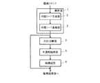
図1は、本発明の第1の実施の形態を示すブロック図である。図中、1は解析部、2は中間コード生成部、3は中間コード蓄積部、4はスキャンライン分解部、5は半透明処理部、6は再構成部である。解析部1は、入力された描画コマンドを解析し、描画コマンド中に半透明処理が指定されているか否かを判定する。半透明処理が指定されていれば、ここでは描画コマンドに従ってスキャンラインの集合に分解する。図1に示す例では、解析部1は描画コマンドを一旦バンド単位で中間コードに変換し、バンド単位に半透明処理の指定の有無を判定し、半透明処理の指定を含むバンドについてスキャンラインの集合への分解を行う。そのための構成として中間コード生成部2、中間コード蓄積部3、スキャンライン分解部4等を含んで構成されている。 FIG. 1 is a block diagram showing a first embodiment of the present invention. In the figure, 1 is an analysis unit, 2 is an intermediate code generation unit, 3 is an intermediate code storage unit, 4 is a scanline decomposition unit, 5 is a translucent processing unit, and 6 is a reconstruction unit. The
中間コード生成部2は、描画コマンドを解析してバンド単位で中間コードを生成して中間コード蓄積部3に格納する。生成する中間コードは後段の描画処理において利用するものである。中間コードの生成の際に、描画コマンドで描画される図形の外接矩形情報についても生成し、中間コード蓄積部3に格納する。 The intermediate
中間コード蓄積部3は、中間コード生成部2で生成された中間コードをバンド単位でアクセス可能なように蓄積する。また、同じく中間コード生成部2で生成した外接矩形情報についても蓄積しておく。 The intermediate
スキャンライン分解部4は、バンド単位に、そのバンドに含まれる中間コードの生成の元となった描画コマンドにおいて半透明処理が指定されているか否かを判定し、半透明処理が指定されている場合には、そのバンドについて中間コードをスキャンラインの集合に分解する。 The
半透明処理部5は、スキャンライン分解部4で分解された描画図形ごとのスキャンラインの集合を受け取り、描画コマンドにおいて半透明処理が指定されていた描画図形のスキャンラインの集合について、それらのスキャンラインと同一ラインに存在する他の描画図形のスキャンラインとの重なりを判定し、重なり部分について半透明処理を行う。この半透明処理の際には、重なり部分とその他の部分を分割し、それぞれ別の描画図形として、新たなスキャンラインの集合とする。なお、重なりの判定の際には、中間コード生成部2において描画コマンドの解析の際に生成した外接矩形情報を利用し、外接矩形情報が重なっている描画図形についてのみ重なり判定を行うようにして、処理速度を向上させることができる。 The
再構成部6は、半透明処理部5による半透明処理後のスキャンラインの集合から、後段の描画処理において利用できる平面状マップを生成する。なお、後段の描画処理がスキャンラインの集合のままで描画処理が可能であれば、平面マップの生成を行わなくてもよい。 The
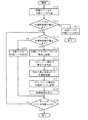
図2は、本発明の第1の実施の形態における動作の一例を示すフローチャートである。S11において、中間コード生成部2は描画コマンドを解析し、1ページ分の中間コードをバンドごとに生成して中間コード蓄積部3に格納する。このとき、それぞれの描画図形の外接矩形情報についても生成し、中間コード蓄積部3に格納する。 FIG. 2 is a flowchart showing an example of the operation according to the first embodiment of the present invention. In S <b> 11, the intermediate
S12において、1ページ分の描画コマンド中に半透明処理が指定された描画コマンドが存在したか否かを判定し、存在しなければスキャンラインの集合への分解は行わず、S21において中間コード蓄積部3に格納されている1ページ分のすべてのバンドについて、中間コードを後段の描画処理部へ送る。これによって、半透明処理が行われない場合に、スキャンラインの集合への分解処理など、不要な処理を削減することができ、処理を高速化するとともにスキャンラインの集合への分解によって必要となるメモリ量を削減することができる。 In S12, it is determined whether or not there is a drawing command for which translucent processing is specified among drawing commands for one page. If there is no drawing command, decomposition into a set of scan lines is not performed, and intermediate code storage is performed in S21. For all the bands for one page stored in the
半透明処理が指定された描画コマンドが存在していた場合には、以下、バンドごとに処理を行ってゆく。S13において、バンド内に半透明処理が指定された描画コマンドによって描画される図形が存在するか否かを判定する。バンド内に半透明処理が指定された描画コマンドによって描画される図形が存在しなければ、スキャンラインの集合への分解は行わず、S20において当該バンドについて中間コード蓄積部3に格納されている中間コードを後段の描画処理部へ送って、当該バンドの処理を終える。これによって、バンド単位でも半透明処理が不要であればスキャンラインの集合への分解処理などを削減でき、処理の高速化とともに必要とするメモリ量を低減することができる。 If there is a drawing command for which translucent processing is specified, the processing is performed for each band. In S13, it is determined whether or not there is a figure to be drawn by a drawing command for which translucent processing is designated in the band. If there is no figure to be drawn by a drawing command for which translucent processing is specified in the band, the image is not decomposed into a set of scan lines, and the intermediate code stored in the intermediate
バンド内に半透明処理が指定された描画コマンドによって描画される図形が存在する場合には、S14において、中間コード蓄積部3に格納されている当該バンドの中間コードに基づいて、スキャンライン分解部4においてそれぞれの描画図形についてスキャンラインの集合に分解する。 If there is a figure to be drawn by the drawing command for which the translucent processing is designated in the band, the scan line decomposing unit based on the intermediate code of the band stored in the intermediate
S15において、半透明処理部5は半透明処理を行う描画図形のスキャンラインと同一ラインに存在する他の描画図形のスキャンラインとの重なり判定を、スキャンラインごとに行う。この判定には、外接矩形情報を利用することができる。そしてS16において、重なり部分を抽出して半透明処理を実施する。なお、重なり部分の抽出によって、重なり部分と重ならない部分とは分離される。 In S15, the
S17において、必要に応じて再構成部6によりスキャンラインの集合から平面状マップを作成し、S18において、半透明処理後のスキャンラインの集合あるいは平面状マップを後段の描画処理部へ送って、当該バンドの処理を終える。 In S17, the
S19において、1ページ内のすべてのバンドについて処理を行ったか否かを判定し、未処理のバンドが残っている場合にはS13に戻って、未処理のバンドについて上述のような処理を行う。すべてのバンドについて処理を終えたら、この半透明処理を終える。なお、描画する画像が複数ページ存在する場合には、上述のような処理をそれぞれのページごとに行えばよい。 In S19, it is determined whether or not the processing has been performed for all the bands in one page. If there is an unprocessed band, the process returns to S13 and the above-described processing is performed for the unprocessed band. When the processing is completed for all the bands, the translucent processing is finished. When there are a plurality of images to be drawn, the above-described process may be performed for each page.
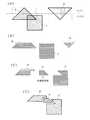
図3は、本発明の第1の実施の形態における動作の具体例の説明図である。上述の動作を、具体例を用いて説明する。図3に示した例では、図3(A)に示したように、描画図形a,b,cを描画しようとしたものである。これらの描画図形を描画するための描画コマンドが入力される。ここで、描画図形cを描画するための描画コマンドには、半透明処理が指定されているものとする。従って、1ページ内に半透明処理が指定された描画コマンドが存在することになる。 FIG. 3 is an explanatory diagram of a specific example of the operation according to the first embodiment of this invention. The above operation will be described using a specific example. In the example shown in FIG. 3, the drawing figures a, b, and c are to be drawn as shown in FIG. A drawing command for drawing these drawing figures is input. Here, it is assumed that semi-transparent processing is specified for the drawing command for drawing the drawing figure c. Therefore, there is a drawing command in which translucent processing is designated within one page.
これらの描画図形を描画するための描画コマンドは、それぞれ、中間コードに変換される。このとき、バンド単位で中間コードが生成される。図3(A)においてはバンドの境界を一点鎖線によって示している。描画図形aは、上部の台形の部分と、下部の三角形の部分に分解され、それぞれのバンドの中間コードが生成される。描画図形bは、上部の三角形の部分と、下部の台形部分に分解され、それぞれのバンドの中間コードが生成される。なお、いずれの描画図形も、破線で示す外接矩形情報が生成される。 Each drawing command for drawing these drawing figures is converted into an intermediate code. At this time, an intermediate code is generated for each band. In FIG. 3A, the band boundary is indicated by a one-dot chain line. The drawing figure a is decomposed into an upper trapezoidal part and a lower triangular part, and an intermediate code of each band is generated. The drawing figure b is decomposed into an upper triangular part and a lower trapezoidal part, and an intermediate code of each band is generated. Note that circumscribed rectangle information indicated by a broken line is generated for each drawing figure.
上部のバンド1には、描画図形aの上部の台形部分と描画図形bの上部の三角形部分が存在する。描画図形a及びbは半透明処理が指定されていないので、バンド1については半透明処理を行う必要がない。従って中間コードのまま後段の描画処理部などへ出力される。 The
バンド2については、半透明処理が指定された描画図形cが存在する。従って、バンド2に存在する描画図形aの下部の三角形部分、描画図形bの下部の台形部分、描画図形cについて、スキャンライン分解部4でスキャンラインの集合に分解される。この状態を図3(B)に示している。 For
描画図形cのそれぞれのスキャンラインについて、他の描画図形との重なり判定を行う。ここで、描画図形aの外接矩形と描画図形cの外接矩形(描画図形cそのもの)との重なりは存在しないので、描画図形aについては重なり判定対象から除外する。描画図形bについては描画図形cと外接矩形が重なるので、スキャンラインの重なり判定対象となる。従って、描画図形cのそれぞれのスキャンラインと同一ラインに存在する描画図形bのスキャンラインについて、重なりを判定してゆく。このようなラインごとの処理は非常に簡単に行うことができる。 For each scan line of the drawing figure c, an overlap determination with another drawing figure is performed. Here, since there is no overlap between the circumscribed rectangle of the drawing figure a and the circumscribed rectangle of the drawing figure c (the drawing figure c itself), the drawing figure a is excluded from the overlap determination target. As for the drawing figure b, the drawing figure c and the circumscribed rectangle overlap with each other, so that the drawing line b is a target for determining the overlap of the scan lines. Therefore, the overlap is determined for the scan lines of the drawing figure b existing on the same line as the scan lines of the drawing figure c. Such processing for each line can be performed very easily.
そして、重なっている部分を抽出し、半透明処理を施す。これによって、図3(C)に示すように、描画図形bの描画図形cと重なっていない部分(描画図形d)と、描画図形bと描画図形cとが重なって半透明処理が施された部分(描画図形e)と、描画図形cの描画図形bと重なっていない部分(描画図形f)とに分離され、それぞれのスキャンラインの集合が得られる。これらを再構成部6で必要に応じて平面状マップに再構成する。最終的に得られた平面状マップを図3(D)に示している。なお、図3(D)においては、描画図形d,e,fの間をあけて示し、理解の一助としているが、実際に描画される際には間は空かない。また描画図形aについては省略している。 And the overlapping part is extracted and a translucent process is performed. As a result, as shown in FIG. 3C, the portion of the drawing figure b that does not overlap with the drawing figure c (drawing figure d) overlaps with the drawing figure b and the drawing figure c, and the translucent processing is performed. A part (drawing figure e) and a part (drawing figure f) that does not overlap the drawing figure b of the drawing figure c are separated, and a set of respective scan lines is obtained. These are reconstructed into a planar map by the
このようにして、半透明処理が指定されている場合には、スキャンラインの集合を生成し、スキャンラインごとに重なりの判定と半透明処理を行うことによって、簡単な処理によって、高速に処理を行うことができる。 In this way, when translucent processing is designated, a set of scan lines is generated, and by performing overlap determination and translucent processing for each scan line, processing can be performed at high speed by simple processing. It can be carried out.
図4は、本発明の第2の実施の形態を示すブロック図である。図中、図1と同様の部分には同じ符号を付して説明を省略する。7は台形分解部である。上述の第1の実施の形態では、半透明処理が指定されていた場合に中間コードからスキャンラインの集合に分解する例を示した。この図4に示した例では、中間コードから台形(矩形を含む。以下同様)の集合に分解する例を示している。 FIG. 4 is a block diagram showing a second embodiment of the present invention. In the figure, the same parts as those in FIG.
台形分解部7は、バンド単位に、そのバンドに含まれる中間コードの生成の元となった描画コマンドにおいて半透明処理が指定されているか否かを判定し、半透明処理が指定されている場合には、そのバンドについて中間コードを所定の方向に平行な辺を含む台形の集合に分解する。なお、分解する台形は、通常は主走査ライン方向に平行な辺を含むものであり、上述のそれぞれのスキャンラインに対応した台形に分解される。 The
半透明処理部5は、台形分解部7で分解された描画図形ごとの台形の集合を受け取り、描画コマンドにおいて半透明処理が指定されていた描画図形の台形の集合について、所定の方向(例えば主走査ライン方向)に位置する他の描画図形の台形について重なりを判定し、重なり部分について半透明処理を行う。この半透明処理の際には、重なり部分とその他の部分を分割し、それぞれ別の描画図形として、新たな台形の集合とする。なお、この場合も外接矩形情報を利用できることは第1の実施の形態と同様である。 The
なお、他の構成は、スキャンラインの集合の代わりに台形の集合を扱う以外は上述の第1の実施の形態と同様であるので、ここでは説明を省略する。また、動作についても同様であるので、同じく説明を省略する。 Other configurations are the same as those in the first embodiment described above except that a trapezoidal set is used instead of a scanline set, and the description thereof is omitted here. Since the operation is the same, the description thereof is omitted.
図5は、本発明の第2の実施の形態における動作の具体例の説明図である。ここでは図3で示した例と同様の図形を描画するものとする(図5(A))。バンド2において半透明処理が指定された描画図形cが存在するため、台形の集合への分解を行う。すなわち、バンド2に存在する描画図形aの下部の三角形部分、描画図形bの下部の台形部分、描画図形cについて、台形分解部7で台形の集合に分解される。この状態を図5(B)に示している。 FIG. 5 is an explanatory diagram of a specific example of the operation according to the second embodiment of the present invention. Here, a figure similar to the example shown in FIG. 3 is drawn (FIG. 5A). Since there is a drawing figure c in which translucent processing is designated in
このうち、描画図形bと描画図形cと外接矩形が重なるので、描画図形cのそれぞれの台形と同一ラインに存在する描画図形bの台形について、重なりを判定してゆく。このような台形間の重なり判定も、簡単に行うことができる。 Among these, since the drawing figure b, the drawing figure c, and the circumscribed rectangle overlap, the overlap is determined for the trapezoid of the drawing figure b existing on the same line as each trapezoid of the drawing figure c. Such overlap determination between trapezoids can also be easily performed.
そして、重なっている部分を抽出し、半透明処理を施す。これによって、図5(C)に示すように、描画図形bの描画図形cと重なっていない部分(描画図形d)と、描画図形bと描画図形cとが重なって半透明処理が施された部分(描画図形e)と、描画図形cの描画図形bと重なっていない部分(描画図形f)とに分離され、それぞれの台形の集合が得られる。これらを再構成部6で必要に応じて平面状マップに再構成する。最終的に得られた平面状マップは上述の図3(D)と同様の結果が得られる。 And the overlapping part is extracted and a translucent process is performed. As a result, as shown in FIG. 5C, the portion (drawing figure d) of the drawing figure b that does not overlap the drawing figure c overlaps the drawing figure b and the drawing figure c, and the translucent processing is performed. A part (drawing figure e) and a part (drawing figure f) that does not overlap the drawing figure b of the drawing figure c are separated, and a set of respective trapezoids is obtained. These are reconstructed into a planar map by the
このようにして、半透明処理が指定されている場合には、台形の集合を生成し、台形ごとに重なりの判定と半透明処理を行うことによって、簡単な処理により、高速に処理を行うことができる。 In this way, when semi-transparent processing is specified, a set of trapezoids is generated, and by performing overlap determination and semi-transparent processing for each trapezoid, processing can be performed at high speed with simple processing. Can do.
なお、上述の各例においては描画コマンドから中間コードを生成しているが、例えば後段の描画処理部が描画コマンドのまま受け取る構成の場合には、中間コードに変換することなく、処理を行ってもよい。また、既に述べたように再構成部6を設けずに構成することもできる。 In each of the above examples, the intermediate code is generated from the drawing command. However, for example, when the drawing processing unit in the subsequent stage receives the drawing command as it is, the processing is performed without converting to the intermediate code. Also good. Further, as already described, the
1…解析部、2…中間コード生成部、3…中間コード蓄積部、4…スキャンライン分解部、5…半透明処理部、6…再構成部、7…台形分解部。 DESCRIPTION OF
Claims (12)
Translated fromJapanesePriority Applications (1)
| Application Number | Priority Date | Filing Date | Title |
|---|---|---|---|
| JP2003420072AJP4412464B2 (en) | 2003-12-17 | 2003-12-17 | Image processing apparatus and image processing method |
Applications Claiming Priority (1)
| Application Number | Priority Date | Filing Date | Title |
|---|---|---|---|
| JP2003420072AJP4412464B2 (en) | 2003-12-17 | 2003-12-17 | Image processing apparatus and image processing method |
Publications (2)
| Publication Number | Publication Date |
|---|---|
| JP2005182314A JP2005182314A (en) | 2005-07-07 |
| JP4412464B2true JP4412464B2 (en) | 2010-02-10 |
Family
ID=34781753
Family Applications (1)
| Application Number | Title | Priority Date | Filing Date |
|---|---|---|---|
| JP2003420072AExpired - Fee RelatedJP4412464B2 (en) | 2003-12-17 | 2003-12-17 | Image processing apparatus and image processing method |
Country Status (1)
| Country | Link |
|---|---|
| JP (1) | JP4412464B2 (en) |
Families Citing this family (3)
| Publication number | Priority date | Publication date | Assignee | Title |
|---|---|---|---|---|
| JP2007221227A (en)* | 2006-02-14 | 2007-08-30 | Konica Minolta Business Technologies Inc | Trapping processing support apparatus, printer, method of deciding trapping extension region, and computer program |
| JP5227898B2 (en)* | 2009-05-28 | 2013-07-03 | 京セラドキュメントソリューションズ株式会社 | Image forming apparatus and image forming program |
| JP5920135B2 (en)* | 2012-09-18 | 2016-05-18 | 富士ゼロックス株式会社 | Image processing apparatus and program |
- 2003
- 2003-12-17JPJP2003420072Apatent/JP4412464B2/ennot_activeExpired - Fee Related
Also Published As
| Publication number | Publication date |
|---|---|
| JP2005182314A (en) | 2005-07-07 |
Similar Documents
| Publication | Publication Date | Title |
|---|---|---|
| Lin et al. | Roi tanh-polar transformer network for face parsing in the wild | |
| US7269298B2 (en) | Image processing device, image processing method, and record medium on which the same is recorded | |
| JP2608571B2 (en) | Apparatus and method for vectorizing input scanned image data | |
| JP2007241878A (en) | Drawing apparatus, drawing method, and drawing program | |
| JPH04104324A (en) | Program generating device | |
| JPH10105361A (en) | Method and system for specifying object | |
| JP4077904B2 (en) | Information processing apparatus and method | |
| JPS6180374A (en) | Microprocessing method and apparatus for veriable scanning area | |
| JP4412464B2 (en) | Image processing apparatus and image processing method | |
| US7554554B2 (en) | Rendering apparatus | |
| JP4809683B2 (en) | Analysis model generation apparatus, analysis model generation method, and analysis model generation program | |
| JP4775723B2 (en) | Image processing apparatus and image processing program | |
| JP2022124681A (en) | Tissue image analysis device and tissue image analysis method | |
| CN112434763A (en) | Chinese character skeleton generating method based on computer | |
| JP4390523B2 (en) | Segmentation of composite image by minimum area | |
| JP2002334341A (en) | Image processor | |
| JP2006072839A (en) | Image processing method, image processing apparatus, image processing program, and recording medium | |
| JP2007026285A (en) | Image processor and image processing program | |
| US8941881B2 (en) | Method and apparatus for rasterizing transparent page | |
| JP3750363B2 (en) | Drawing information processing apparatus and drawing information processing method | |
| JP4548062B2 (en) | Image processing device | |
| JPH10319935A (en) | Character generator | |
| KR20180006305A (en) | Storage medium, facetization processing method, facet extracting method, and information processing device | |
| JP2009075805A (en) | Image forming apparatus | |
| JP2006237858A (en) | Image processing apparatus, image processing method, program for causing computer to execute the method, and recording medium |
Legal Events
| Date | Code | Title | Description |
|---|---|---|---|
| A621 | Written request for application examination | Free format text:JAPANESE INTERMEDIATE CODE: A621 Effective date:20061127 | |
| A131 | Notification of reasons for refusal | Free format text:JAPANESE INTERMEDIATE CODE: A131 Effective date:20090729 | |
| A521 | Written amendment | Free format text:JAPANESE INTERMEDIATE CODE: A523 Effective date:20090924 | |
| TRDD | Decision of grant or rejection written | ||
| A01 | Written decision to grant a patent or to grant a registration (utility model) | Free format text:JAPANESE INTERMEDIATE CODE: A01 Effective date:20091028 | |
| A01 | Written decision to grant a patent or to grant a registration (utility model) | Free format text:JAPANESE INTERMEDIATE CODE: A01 | |
| FPAY | Renewal fee payment (event date is renewal date of database) | Free format text:PAYMENT UNTIL: 20121127 Year of fee payment:3 | |
| R150 | Certificate of patent or registration of utility model | Free format text:JAPANESE INTERMEDIATE CODE: R150 | |
| A61 | First payment of annual fees (during grant procedure) | Free format text:JAPANESE INTERMEDIATE CODE: A61 Effective date:20091110 | |
| FPAY | Renewal fee payment (event date is renewal date of database) | Free format text:PAYMENT UNTIL: 20121127 Year of fee payment:3 | |
| FPAY | Renewal fee payment (event date is renewal date of database) | Free format text:PAYMENT UNTIL: 20131127 Year of fee payment:4 | |
| LAPS | Cancellation because of no payment of annual fees |