JP4411062B2 - Super abrasive wire saw winding structure, super abrasive wire saw cutting device, and super abrasive wire saw winding method - Google Patents
Super abrasive wire saw winding structure, super abrasive wire saw cutting device, and super abrasive wire saw winding methodDownload PDFInfo
- Publication number
- JP4411062B2 JP4411062B2JP2003429425AJP2003429425AJP4411062B2JP 4411062 B2JP4411062 B2JP 4411062B2JP 2003429425 AJP2003429425 AJP 2003429425AJP 2003429425 AJP2003429425 AJP 2003429425AJP 4411062 B2JP4411062 B2JP 4411062B2
- Authority
- JP
- Japan
- Prior art keywords
- wire saw
- superabrasive
- winding
- superabrasive wire
- saw
- Prior art date
- Legal status (The legal status is an assumption and is not a legal conclusion. Google has not performed a legal analysis and makes no representation as to the accuracy of the status listed.)
- Expired - Fee Related
Links
Images


Classifications
- B—PERFORMING OPERATIONS; TRANSPORTING
- B65—CONVEYING; PACKING; STORING; HANDLING THIN OR FILAMENTARY MATERIAL
- B65H—HANDLING THIN OR FILAMENTARY MATERIAL, e.g. SHEETS, WEBS, CABLES
- B65H54/00—Winding, coiling, or depositing filamentary material
- B65H54/02—Winding and traversing material on to reels, bobbins, tubes, or like package cores or formers
- B65H54/28—Traversing devices; Package-shaping arrangements
- B65H54/2848—Arrangements for aligned winding
- B65H54/2854—Detection or control of aligned winding or reversal
- B65H54/2869—Control of the rotating speed of the reel or the traversing speed for aligned winding
- B65H54/2872—Control of the rotating speed of the reel or the traversing speed for aligned winding by detection of the incidence angle
- B—PERFORMING OPERATIONS; TRANSPORTING
- B65—CONVEYING; PACKING; STORING; HANDLING THIN OR FILAMENTARY MATERIAL
- B65H—HANDLING THIN OR FILAMENTARY MATERIAL, e.g. SHEETS, WEBS, CABLES
- B65H54/00—Winding, coiling, or depositing filamentary material
- B65H54/02—Winding and traversing material on to reels, bobbins, tubes, or like package cores or formers
- B65H54/28—Traversing devices; Package-shaping arrangements
- B—PERFORMING OPERATIONS; TRANSPORTING
- B23—MACHINE TOOLS; METAL-WORKING NOT OTHERWISE PROVIDED FOR
- B23D—PLANING; SLOTTING; SHEARING; BROACHING; SAWING; FILING; SCRAPING; LIKE OPERATIONS FOR WORKING METAL BY REMOVING MATERIAL, NOT OTHERWISE PROVIDED FOR
- B23D57/00—Sawing machines or sawing devices not covered by one of the preceding groups B23D45/00 - B23D55/00
- B23D57/003—Sawing machines or sawing devices working with saw wires, characterised only by constructional features of particular parts
- B23D57/0061—Sawing machines or sawing devices working with saw wires, characterised only by constructional features of particular parts of devices for guiding or feeding saw wires
- B—PERFORMING OPERATIONS; TRANSPORTING
- B23—MACHINE TOOLS; METAL-WORKING NOT OTHERWISE PROVIDED FOR
- B23D—PLANING; SLOTTING; SHEARING; BROACHING; SAWING; FILING; SCRAPING; LIKE OPERATIONS FOR WORKING METAL BY REMOVING MATERIAL, NOT OTHERWISE PROVIDED FOR
- B23D61/00—Tools for sawing machines or sawing devices; Clamping devices for these tools
- B23D61/18—Sawing tools of special type, e.g. wire saw strands, saw blades or saw wire equipped with diamonds or other abrasive particles in selected individual positions
- B23D61/185—Saw wires; Saw cables; Twisted saw strips
- B—PERFORMING OPERATIONS; TRANSPORTING
- B24—GRINDING; POLISHING
- B24B—MACHINES, DEVICES, OR PROCESSES FOR GRINDING OR POLISHING; DRESSING OR CONDITIONING OF ABRADING SURFACES; FEEDING OF GRINDING, POLISHING, OR LAPPING AGENTS
- B24B27/00—Other grinding machines or devices
- B24B27/06—Grinders for cutting-off
- B24B27/0633—Grinders for cutting-off using a cutting wire
- Y—GENERAL TAGGING OF NEW TECHNOLOGICAL DEVELOPMENTS; GENERAL TAGGING OF CROSS-SECTIONAL TECHNOLOGIES SPANNING OVER SEVERAL SECTIONS OF THE IPC; TECHNICAL SUBJECTS COVERED BY FORMER USPC CROSS-REFERENCE ART COLLECTIONS [XRACs] AND DIGESTS
- Y10—TECHNICAL SUBJECTS COVERED BY FORMER USPC
- Y10T—TECHNICAL SUBJECTS COVERED BY FORMER US CLASSIFICATION
- Y10T83/00—Cutting
- Y10T83/929—Tool or tool with support
- Y10T83/9292—Wire tool
Landscapes
- Engineering & Computer Science (AREA)
- Mechanical Engineering (AREA)
- Finish Polishing, Edge Sharpening, And Grinding By Specific Grinding Devices (AREA)
- Processing Of Stones Or Stones Resemblance Materials (AREA)
- Polishing Bodies And Polishing Tools (AREA)
Description
Translated fromJapaneseこの発明は、一般的には、超砥粒ワイヤソー巻き付け構造、超砥粒ワイヤソー切断装置および超砥粒ワイヤソーの巻き付け方法に関し、より特定的には、シリコンインゴットからのシリコンウェハのスライシングや、金属、樹脂、鉱石、ガラス、サファイア、水晶、SiCおよび化合物半導体など各種材料の切断加工に用いられる固定砥粒方式の超砥粒ワイヤソーの巻き付け構造、超砥粒ワイヤソー切断装置および超砥粒ワイヤソーの巻き付け方法に関する。 The present invention generally relates to a superabrasive wire saw winding structure, a superabrasive wire saw cutting apparatus, and a superabrasive wire saw winding method, and more specifically, slicing of a silicon wafer from a silicon ingot, metal, Winding structure of superabrasive wire saw of fixed abrasive type used for cutting various materials such as resin, ore, glass, sapphire, crystal, SiC and compound semiconductor, superabrasive wire saw cutting device, and superabrasive wire saw winding method About.
従来、芯線の表面にダイヤモンド砥粒を固着した、固定砥粒方式のダイヤモンドワイヤソーが、超砥粒ワイヤソーの一例として提案されている。このダイヤモンドワイヤソーを用いると、極めて良好な切れ味で金属等の材料を切断することができる。また、研磨液と砥粒とを混合したスラリーが不要であり、水溶性または不水溶性の切削液を利用することができる。このため、切断時に飛散するスラッジによって切断装置およびその周辺が汚染されることを抑制でき、作業環境の改善を図ることができる。 Conventionally, a fixed-abrasive diamond wire saw in which diamond abrasive grains are fixed to the surface of a core wire has been proposed as an example of a superabrasive wire saw. When this diamond wire saw is used, a material such as metal can be cut with a very good sharpness. Moreover, the slurry which mixed abrasive | polishing liquid and the abrasive grain is unnecessary, and a water-soluble or water-insoluble cutting fluid can be utilized. For this reason, it can suppress that a cutting device and its periphery are contaminated with the sludge scattered at the time of a cutting | disconnection, and can aim at the improvement of a working environment.
加えて、このダイヤモンドワイヤソーによれば、数km以上といった長尺で作製することが可能となる。これにより、複数の切断加工を同時に行なうことができるため、スラリーを用いたマルチワイヤソー方式と比較して数倍以上の切断速度を得ることができる。このような固定砥粒方式の超砥粒ワイヤソーは、たとえば、特開平8−126953号公報(特許文献1)、特開平9−155631号公報(特許文献2)および国際公開第98/35784号パンフレット(特許文献3)に開示されている。 In addition, according to this diamond wire saw, it is possible to produce a long length of several km or more. Thereby, since a plurality of cutting processes can be performed at the same time, a cutting speed several times or more can be obtained as compared with a multi-wire saw system using a slurry. Such fixed abrasive type superabrasive wire saws are disclosed in, for example, JP-A-8-126953 (Patent Document 1), JP-A-9-155631 (Patent Document 2), and International Publication No. 98/35784 pamphlet. (Patent Document 3).
また別に、特開平4−351222号公報には、ボンディング作業時に繰り出し不良のない状態で、往復多層状に巻き取られたボンディングワイヤ巻線が開示されている(特許文献4)。特許文献4に開示されたボンディングワイヤ巻線では、スプールの一端から他端に向けて巻き取られるボンディングワイヤと、さらにスプールの他端から一端に向けて巻き取られるボンディングワイヤとが交差する角度が0.03°以上に設定されている。 In addition, Japanese Patent Laid-Open No. 4-351222 discloses a bonding wire winding wound in a reciprocating multilayer shape in a state where there is no feeding failure during bonding work (Patent Document 4). In the bonding wire winding disclosed in
さらに、特開2002−18517号公報には、ボビンへの線材の巻き取り不良を防止することを目的とした線材巻き取り装置が開示されている(特許文献5)。特許文献5に開示された線材巻き取り装置は、電線、ワイヤ、ケーブルをボビンに巻き取るための装置である。線材巻き取り装置には、ボビンの鍔位置を検出可能な鍔検出センサが設けられており、そのセンサが鍔位置を検出するたびに、線材を案内するトラバーサの移動方向が反転される。 Furthermore, Japanese Patent Application Laid-Open No. 2002-18517 discloses a wire winding device intended to prevent winding failure of a wire around a bobbin (Patent Document 5). The wire winding device disclosed in Patent Document 5 is a device for winding an electric wire, a wire, and a cable onto a bobbin. The wire winding device is provided with a wrinkle detection sensor that can detect the wrinkle position of the bobbin, and each time the sensor detects the wrinkle position, the moving direction of the traverser that guides the wire is reversed.
さらに、特開2000−349120号公報には、ワイヤに傷不良が発生するまでのガイドの寿命を長くすることを目的とした半導体素子用ボンディングワイヤの巻き取り方法が開示されている(特許文献6)。特許文献6に開示された巻き取り方法では、非回転式の巻き取りガイドが用いられ、その巻き取りガイドは、ダイヤモンドライクカーボン膜で被覆した硬質基材から形成されている。
上述の超砥粒ワイヤソーを用いて切断加工を行なう場合、超砥粒ワイヤソーは、リールに巻かれた状態とされ、その状態から加工物に向けて繰り出されたり、回収されたりする。このため、超砥粒ワイヤソーを切断装置に装着可能な状態とするためには、まず超砥粒ワイヤソーを切断装置に応じたリールに巻き付ける必要がある。図8は、従来において、リールに巻かれた超砥粒ワイヤソーを示す断面図である。 When performing cutting using the above-described superabrasive wire saw, the superabrasive wire saw is wound around a reel, and is fed out or collected from the state toward a workpiece. For this reason, in order to make a superabrasive wire saw attachable to a cutting device, it is necessary to first wind the superabrasive wire saw around a reel corresponding to the cutting device. FIG. 8 is a cross-sectional view showing a conventional superabrasive wire saw wound around a reel.
図8を参照して、超砥粒ワイヤソー310は、芯線311と、結合材312を用いて芯線311の表面に固着された複数の超砥粒313とを備える。超砥粒313は、遊離砥粒方式の場合とは異なり、結合材312の表面から突出するように設けられている。超砥粒ワイヤソー310は、円筒状に形成されたリール301の表面に、その表面の両端の間を往復しながら多層に巻き付けられている。超砥粒ワイヤソー310は、リール301の表面の両端の間で一定のピッチで巻き付けられており、隣り合う超砥粒ワイヤソー310同士が接触している。 Referring to FIG. 8,
このような状態に超砥粒ワイヤソー310をリール301に巻き付ける場合、隣り合う超砥粒ワイヤソー310同士が擦れ合うため、結合材312が超砥粒313によって傷付けられるという問題が発生する。また、超砥粒313同士が強く衝突することによって、超砥粒313が芯線311の表面から欠落するという問題も発生する。またこのような問題は、切断加工時において、図8に示す状態と同様の状態で超砥粒ワイヤソー310を加工物に向けて繰り出したり回収したりする場合にも発生する。 When the
そこでこの発明の目的は、上記の課題を解決することであり、結合材の損傷および超砥粒の欠落を軽減できる超砥粒ワイヤソー巻き付け構造、超砥粒ワイヤソー切断装置および超砥粒ワイヤソーの巻き付け方法を提供することである。 SUMMARY OF THE INVENTION Accordingly, an object of the present invention is to solve the above-described problems, and a superabrasive wire saw winding structure, a superabrasive wire saw cutting device, and a superabrasive wire saw winding that can reduce damage to a binder and loss of superabrasive grains. Is to provide a method.
この発明に従った超砥粒ワイヤソー巻き付け構造は、平均直径Dで形成された超砥粒ワイヤソーと、リール部とを備える。超砥粒ワイヤソーは、芯線と、芯線の表面を取り囲む結合材と、結合材によって芯線の表面に固着された複数の超砥粒とを含む。リール部は、一方端と他方端とを有する外周面を含む。加工物に向けて順次繰り出される超砥粒ワイヤソーは、一方端と他方端との間で往復しながら外周面に多層に巻き付けられる。超砥粒ワイヤソーが一方端と他方端との間で外周面に巻き付けられるピッチPは、1.1D<P<(31/2)Dの関係を満たす。A superabrasive wire saw winding structure according to the present invention includes a superabrasive wire saw formed with an average diameter D and a reel portion. The superabrasive wire saw includes a core wire, a binding material surrounding the surface of the core wire, and a plurality of superabrasive grains fixed to the surface of the core wire by the binding material. The reel portion includes an outer peripheral surface having one end and the other end. The superabrasive wire saw that is sequentially fed toward the workpiece is wound around the outer peripheral surface in multiple layers while reciprocating between one end and the other end. The pitch P at which the superabrasive wire saw is wound around the outer peripheral surface between one end and the other end satisfies the relationship1.1D <P <(31/2) D.
このように構成された超砥粒ワイヤソー巻き付け構造によれば、超砥粒ワイヤソーが巻き付けられるピッチPが超砥粒ワイヤソーの平均直径Dの1.1倍よりも大きいため、超砥粒ワイヤソーをリール部の表面に巻き付ける際に、巻き付ける超砥粒ワイヤソーと、隣り合う位置に巻かれた超砥粒ワイヤソーとが強く擦れ合うことを防止できる。また、ピッチPが(31/2)Dよりも小さいため、超砥粒ワイヤソーをリール部の表面に巻き付ける際に、巻き付ける超砥粒ワイヤソーが、下層に巻かれた、互いに隣り合う超砥粒ワイヤソーの隙間に食い込むということがない。これにより、超砥粒ワイヤソーを再びリール部から繰り出す時に、超砥粒ワイヤソー同士が強く擦れ合うことを防止できる。これらの理由から、ピッチPが適正な範囲に設定された本発明によれば、結合材が損傷し、超砥粒が欠落することを軽減させることができる。According to the superabrasive wire saw winding structure configured as described above, the pitch P around which the superabrasive wire saw is wound is larger than1.1 times the average diameter Dof the superabrasive wire saw. When wound around the surface of the part, it is possible to prevent the superabrasive wire saw to be wound and the superabrasive wire saw wound at adjacent positions from being rubbed strongly. The pitch P is(31/2) smaller thanD, and when winding the superabrasive wire saw on the surface of the reel portion, wound superabrasive wire saw is wound around the lower layer, the super abrasive grains adjacent It does not bite into the gap between the wire saws. Thereby, when the superabrasive wire saw is again fed out from the reel portion, it is possible to prevent the superabrasive wire saws from being rubbed strongly. For these reasons, according to the present invention in which the pitch P is set in an appropriate range, it is possible to reduce the damage to the binding material and the loss of superabrasive grains.
このように構成された超砥粒ワイヤソー巻き付け構造によれば、ピッチPが(31/2)Dよりも小さいため、巻き付ける超砥粒ワイヤソーが、2層下に巻かれた超砥粒ワイヤソーに接触するということがない。このため、超砥粒ワイヤソー同士の接触に起因して結合材が損傷し、超砥粒が欠落することを軽減させることができる。According tothe thus constructed superabrasive wire saw windingstructure, sincepitch P is (31/2) less than D, wound superabrasive wire saw, superabrasive wound under two layers There is no contact with the wire saw. For this reason, it can reduce that a binding material is damaged and the superabrasive grain is missing due to contact between the superabrasive wire saws.
また好ましくは、芯線の平均直径がd1であり、超砥粒の平均直径がd2である場合、平均直径d1およびd2は、0.02<d2/d1<0.5の関係を満たす。このように構成された超砥粒ワイヤソー巻き付け構造によれば、d2/d1が0.5よりも小さいため、芯線の平均直径に対して超砥粒の平均直径が大きくなりすぎることがない。このため、芯線の表面に設けられた結合材によって超砥粒を確実に保持することができる。これにより、超砥粒が欠落することをさらに軽減させることができる。また、d2/d1が0.02よりも大きいため、超砥粒がある程度の大きさを有している。これにより、超砥粒が切断時の加工応力に耐え切れず芯線の表面から欠落するという事態を回避することができる。また、超砥粒が細かすぎるために超砥粒ワイヤソーの切れ味が極端に低下するということがない。 Preferably, when the average diameter of the core wire is d1 and the average diameter of the superabrasive grains is d2, the average diameters d1 and d2 satisfy a relationship of 0.02 <d2 / d1 <0.5. According to the superabrasive wire saw winding structure configured in this way, since d2 / d1 is smaller than 0.5, the average diameter of the superabrasive grains does not become too large with respect to the average diameter of the core wire. For this reason, a superabrasive grain can be reliably hold | maintained with the binder provided in the surface of the core wire. Thereby, it can further reduce that superabrasive grain is missing. Moreover, since d2 / d1 is larger than 0.02, the superabrasive grains have a certain size. Thereby, the situation where superabrasive grains cannot endure the processing stress at the time of cutting and is missing from the surface of a core wire can be avoided. Further, since the superabrasive grains are too fine, the sharpness of the superabrasive wire saw is not extremely reduced.
また好ましくは、結合材は、レジンボンド、電着、メタルボンドおよびビトリファイドボンドからなる群より選ばれた少なくとも一種を含む。このように構成された超砥粒ワイヤソー巻き付け構造によれば、超砥粒を芯線の表面に確実に保持し、超砥粒の欠落を防止することができる。 Also preferably, the binder includes at least one selected from the group consisting of resin bonds, electrodeposition, metal bonds, and vitrified bonds. According to the superabrasive wire saw winding structure configured as described above, the superabrasive grains can be reliably held on the surface of the core wire, and the loss of superabrasive grains can be prevented.
この発明に従った超砥粒ワイヤソー切断装置は、上述のいずれかに記載の超砥粒ワイヤソー巻き付け構造を用いて設けられた超砥粒ワイヤソー供給部を備える。このように構成された超砥粒ワイヤソー切断装置によれば、結合材の損傷および超砥粒の欠落が軽減された超砥粒ワイヤソーを用いて、所望の切断加工を行なうことができる。 A superabrasive wire saw cutting apparatus according to the present invention includes a superabrasive wire saw supply unit provided using the superabrasive wire saw winding structure described above. According to the superabrasive wire saw cutting apparatus configured as described above, a desired cutting process can be performed using the superabrasive wire saw in which damage to the binder and lack of superabrasive grains are reduced.
この発明に従った超砥粒ワイヤソーの巻き付け方法は、平均直径Dで形成された超砥粒ワイヤソーと、一方端と他方端とを有する外周面を含むリール部とを準備する工程を備える。超砥粒ワイヤソーは、芯線、芯線の表面を取り囲む結合材および結合材によって芯線の表面に固着された複数の超砥粒を含む。超砥粒ワイヤソーの巻き付け方法は、超砥粒ワイヤソーを一方端と他方端との間で往復させながら外周面に多層に巻き付ける工程をさらに備える。超砥粒ワイヤソーを巻き付ける工程は、一方端と他方端との間で超砥粒ワイヤソーを巻き付けるピッチPが、1.1D<P<(31/2)Dの関係を満たすように超砥粒ワイヤソーを巻き付ける工程を含む。The superabrasive wire saw winding method according to the present invention includes a step of preparing a superabrasive wire saw formed with an average diameter D and a reel portion including an outer peripheral surface having one end and the other end. The superabrasive wire saw includes a core wire, a binding material surrounding the surface of the core wire, and a plurality of superabrasive particles fixed to the surface of the core wire by the binding material. The winding method of the superabrasive wire saw further includes a step of winding the superabrasive wire saw around the outer peripheral surface in multiple layers while reciprocating between the one end and the other end. The step of winding the superabrasive wire saw is performed such that the pitch P for winding the superabrasive wire saw between one end and the other end satisfies the relationship1.1D <P <(31/2) D. A step of winding a wire saw.
このように構成された超砥粒ワイヤソーの巻き付け方法によれば、超砥粒ワイヤソーを巻き付けるピッチPが超砥粒ワイヤソーの平均直径Dの1.1倍よりも大きいため、超砥粒ワイヤソーをリール部の表面に巻き付ける際に、巻き付ける超砥粒ワイヤソーと、隣り合う位置に巻かれた超砥粒ワイヤソーとが強く擦れ合うということがない。また、ピッチPが(31/2)Dよりも小さいため、超砥粒ワイヤソーをリール部の表面に巻き付ける際に、巻き付ける超砥粒ワイヤソーが、下層に巻かれた、互いに隣り合う超砥粒ワイヤソーの隙間に食い込むということがない。これにより、超砥粒ワイヤソーを再びリール部から繰り出す時に、超砥粒ワイヤソー同士が強く擦れ合うことを防止できる。これらの理由から、ピッチPを適正な範囲に設定して超砥粒ワイヤソーを巻き付ける本発明によれば、結合材が損傷し、超砥粒が欠落することを軽減させることができる。According to the winding method of the superabrasive wire saw configured in this way, the pitch P for winding the superabrasive wire saw is larger than1.1 times the average diameter Dof the superabrasive wire saw. When wound around the surface of the part, the superabrasive wire saw to be wound and the superabrasive wire saw wound at the adjacent position do not rub against each other strongly. The pitch P is(31/2) smaller thanD, and when winding the superabrasive wire saw on the surface of the reel portion, wound superabrasive wire saw is wound around the lower layer, the super abrasive grains adjacent It does not bite into the gap between the wire saws. Thereby, when the superabrasive wire saw is again fed out from the reel portion, it is possible to prevent the superabrasive wire saws from being rubbed strongly. For these reasons, according to the present invention in which the super abrasive grain wire saw is wound with the pitch P set in an appropriate range, it is possible to reduce the damage of the binding material and the loss of super abrasive grains.
また好ましくは、超砥粒ワイヤソーを巻き付ける工程は、超砥粒ワイヤソーの破断強度の5%以上50%以下となる巻き付け張力で超砥粒ワイヤソーを巻き付ける工程を含む。このように構成された超砥粒ワイヤソーの巻き付け方法によれば、巻き付け張力が超砥粒ワイヤソーの破断強度の5%以上であるため、いったんリール部に巻き付けた超砥粒ワイヤソーが時間の経過とともに緩むということがない。また、巻き付け張力が超砥粒ワイヤソーの破断強度の50%以下であるため、超砥粒ワイヤソー同士が食い込んで結合材が傷付くということがない。 Preferably, the step of winding the superabrasive wire saw includes the step of winding the superabrasive wire saw with a winding tension that is 5% to 50% of the breaking strength of the superabrasive wire saw. According to the winding method of the superabrasive wire saw configured in this way, the winding tension is 5% or more of the breaking strength of the superabrasive wire saw. There is no loosening. Further, since the winding tension is 50% or less of the breaking strength of the superabrasive wire saw, the superabrasive wire saws do not bite into each other and the binding material is not damaged.
以上説明したように、この発明に従えば、結合材の損傷および超砥粒の欠落を軽減できる超砥粒ワイヤソー巻き付け構造、超砥粒ワイヤソー切断装置および超砥粒ワイヤソーの巻き付け方法を提供することができる。 As described above, according to the present invention, it is possible to provide a superabrasive wire saw winding structure, a superabrasive wire saw cutting device, and a superabrasive wire saw winding method that can reduce damage to a binder and loss of superabrasive grains. Can do.
この発明の実施の形態について、図面を参照して説明する。 Embodiments of the present invention will be described with reference to the drawings.
(実施の形態1)
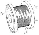
図1は、この発明の実施の形態1における超砥粒ワイヤソー巻き付け構造を備える超砥粒ワイヤソー巻き線を示す斜視図である。図1を参照して、超砥粒ワイヤソー10が、円筒状に形成されたリール1の外周面に多層に巻き付けられている。後に詳細に説明するが、本実施の形態における超砥粒ワイヤソー巻き付け構造では、超砥粒ワイヤソー10が外周面に巻き付けられるピッチPが所定の範囲に設定されている。(Embodiment 1)
1 is a perspective view showing a superabrasive wire saw winding having a superabrasive wire saw winding structure according to
超砥粒ワイヤソー10は、シリコンインゴットからのシリコンウェハのスライシングの他、超硬合金、サーメット、セラミックス、ゲルマニウム、フェライト、センダスト、アルニコ、サマリウムコバルト、ネオジウム磁石、ガラス、水晶、サファイア、石材、耐火レンガ、タイル、樹脂材料、FRP(fiber-glass reinforced plastic:ガラス繊維強化プラスチック)、CFRP(carbon fiber reinforced plastic:炭素繊維強化プラスチック)、グラファイト、砥石、宝石および金属材料などの切断加工に用いられる。 In addition to slicing silicon wafers from silicon ingots, superabrasive wire saw 10 is made of cemented carbide, cermet, ceramics, germanium, ferrite, sendust, alnico, samarium cobalt, neodymium magnet, glass, crystal, sapphire, stone, refractory brick , Tile, resin material, FRP (fiber-glass reinforced plastic), CFRP (carbon fiber reinforced plastic), graphite, grindstone, jewelry and metal materials.
図2は、図1中の超砥粒ワイヤソーを拡大して示す模式図である。図2の一部には、超砥粒ワイヤソーの長手方向の縦断面が示されている。図3は、図2中のIII−III線上に沿った断面を示す模式図である。 FIG. 2 is an enlarged schematic view of the superabrasive wire saw in FIG. A part of FIG. 2 shows a longitudinal section of the superabrasive wire saw in the longitudinal direction. FIG. 3 is a schematic diagram showing a cross section taken along line III-III in FIG.
図2および図3を参照して、超砥粒ワイヤソー10は、線状に延びる芯線11と、芯線11の表面11aを覆う結合材12と、結合材12によって表面11a上に固着された複数の超砥粒13とを備える。超砥粒13は、たとえばダイヤモンド砥粒から形成されており、結合材12の表面12aから一部が突出するように設けられている。 Referring to FIGS. 2 and 3, superabrasive wire saw 10 includes a
超砥粒ワイヤソー10は、平均直径Dを有する。この際、超砥粒ワイヤソー10の長手方向に間隔を隔てた任意の位置に3つの測定地点を選び、これらの地点のそれぞれにおいて、超砥粒ワイヤソー10の直径を3方向で測定し、合計9つの測定値を得る。そして、得られた測定値の平均を算出することによって、超砥粒ワイヤソー10の平均直径Dを求める。 Superabrasive wire saw 10 has an average diameter D. At this time, three measurement points are selected at arbitrary positions spaced apart in the longitudinal direction of the superabrasive wire saw 10, and the diameter of the superabrasive wire saw 10 is measured in three directions at each of these points, for a total of 9 Get two measurements. And the average diameter D of the superabrasive wire saw 10 is calculated | required by calculating the average of the obtained measured value.
芯線11の平均直径d1は、0.01mm以上1mm以下であることが好ましい。芯線11の平均直径d1は、上述の測定法によって同様に求めることができる。芯線11としては、たとえば、鋼線、銅めっきを施した鋼線およびブラスめっきを施した鋼線のいずれか1つを用いることができる。 The average diameter d1 of the
鋼線としては、容易に極細線に仕上げることができ、強度が高いピアノ線が最も好ましい。ピアノ線はそのままでも使用することができるが、保管を容易にし、かつレジンボンドの密着性を良好にして超砥粒の保持力を高めるためには、ピアノ線に銅めっきまたはブラスめっき等の表面処理を施すことが好ましい。 As the steel wire, a piano wire that can be easily finished into a very fine wire and has high strength is most preferable. The piano wire can be used as it is, but in order to facilitate storage and improve the adhesion of the resin bond and increase the holding power of the superabrasive grains, the piano wire has a surface such as copper plating or brass plating. It is preferable to perform the treatment.
その他の材質の芯線としては、炭素繊維、アラミド繊維、ボロン繊維、ガラス繊維のいずれか1種の単線または撚り線を用いることができる。または、炭素繊維、アラミド繊維、ボロン繊維、ガラス繊維のうち2種以上の繊維を混合して撚り線としたものも用いることができる。さらに、これらの撚り線に鋼線を加えた撚り線を芯線として用いることも可能である。 As a core wire of other materials, a single wire or a stranded wire of any one of carbon fiber, aramid fiber, boron fiber, and glass fiber can be used. Alternatively, a stranded wire obtained by mixing two or more kinds of carbon fibers, aramid fibers, boron fibers, and glass fibers can be used. Furthermore, it is also possible to use a stranded wire obtained by adding a steel wire to these stranded wires as a core wire.
超砥粒13の平均直径がd2である場合、芯線11および超砥粒13の平均直径d1およびd2は、0.02<d2/d1<0.5の関係を満たすことが好ましい。この場合、平均直径d1が、たとえば、0.11mm、0.13mm、0.155mm、0.16mm、0.18mm、0.2mmまたは0.5mmである芯線11を用いることができる。また、平均直径d2が、たとえば、0.010mm、0.012mm、0.032mm、0.042mmまたは0.055mmである超砥粒13を用いることができる。このような関係を満たす超砥粒13および芯線11を使用することによって、表面11a上に確実に保持した状態の超砥粒13を切断加工に寄与させることができる。また同時に、優れた切れ味を得ることができる。 When the average diameter of the
結合材12としては、レジンボンド、電着、メタルボンドまたはビトリファイドボンドを用いることができる。また、レジンボンドとメタルボンドとの複合ボンドや、レジンボンドとビトリファイドボンドとの複合ボンドなどの各種の結合材を結合材12として用いることもできる。なお、本実施の形態における効果が特に顕著に得られるのは、レジンボンドまたはレジンボンドを主体とする複合ボンドを用いた場合である。 Resin bond, electrodeposition, metal bond or vitrified bond can be used as the
レジンボンドとして適用できる樹脂としては、弾性率、軟化温度、成形性、物理的特性の観点から、アルキド樹脂、フェノール樹脂、ホルマリン樹脂、ポリウレタン樹脂、ポリエステル樹脂、ポリイミド樹脂、エポキシ樹脂、メラミン樹脂、ユリア樹脂、不飽和ポリエステル樹脂、アクリル樹脂、ポリエステルイミド樹脂、ポリアミドイミド樹脂、ポリエステルウレタン樹脂、ビスマレイミド樹脂、ビスマレイミドトリアジン樹脂、シアナトエステル樹脂、ポリエーテルイミド、ポリパラバン酸、芳香族ポリアミドなどが好ましい。 Resins that can be used as resin bonds include alkyd resin, phenol resin, formalin resin, polyurethane resin, polyester resin, polyimide resin, epoxy resin, melamine resin, urea from the viewpoint of elastic modulus, softening temperature, moldability, and physical properties. Resins, unsaturated polyester resins, acrylic resins, polyester imide resins, polyamide imide resins, polyester urethane resins, bismaleimide resins, bismaleimide triazine resins, cyanate ester resins, polyether imides, polyparabanic acids, aromatic polyamides and the like are preferable.
電着とは、電着によって結合材12を芯線11の表面11aに形成する場合を指し、たとえば、ニッケル(Ni)めっきを結合材12として表面11aに形成する。また、結合材12としてメタルボンドを用いる場合、適当な金属粉と超砥粒13とを混合粉とし、その混合粉を芯線11の表面11aに焼き付ける。 Electrodeposition refers to the case where the
図4は、図1中のIV−IV線上に沿った断面図である。図4では、リール1に実際に巻かれている超砥粒ワイヤソー10の一部のみが模式的に示されている。図4を参照して、リール1は、外周面2と、外周面2の両端から直角方向に立ち上がる内壁5とを有する。外周面2と内壁5とが交差する位置には、一方端3および他方端4が規定されている。 FIG. 4 is a cross-sectional view taken along line IV-IV in FIG. In FIG. 4, only a part of the superabrasive wire saw 10 actually wound on the
超砥粒ワイヤソー10は、まず、一方端3から他方端4に向けてピッチPで外周面2に巻き付けられている(第1層目の超砥粒ワイヤソー101a、101b、101cおよび101d)。第1層目の超砥粒ワイヤソーが他方端4まで巻き付けられた後、超砥粒ワイヤソー10は、既に巻き付けられた超砥粒ワイヤソーの上から次は他方端4から一方端3に向けてピッチPで巻き付けられている(第2層目の超砥粒ワイヤソー102a、102b、102cおよび102d)。さらに、超砥粒ワイヤソー10は、第3層目では一方端3から他方端4に向けて、第4層目では他方端4から一方端3に向けてという具合に、一方端3と他方端4との間を往復しながらピッチPで多層に巻き付けられている。 The superabrasive wire saw 10 is first wound around the outer
このように超砥粒ワイヤソー10が一方端3と他方端4との間で外周面2上に巻き付けられるピッチPは、D<P<2Dの関係を満たしている。また好ましくは、ピッチPは、1.1D<P<1.9Dの関係を満たしている。 Thus, the pitch P by which the superabrasive wire saw 10 is wound on the outer
図5は、図1中に示す超砥粒ワイヤソー巻き線を製造するための巻き付け装置を示す概略図である。図5を参照して、巻き付け装置21は、リール1が取り付けられる回転軸を有し、リール1を所定の速度で回転させるための第1の駆動手段としてのモーター22と、リール1の近傍に配置され、リール1に巻き付けられる超砥粒ワイヤソー10が案内されるトラバーサ24と、トラバーサ24が接続され、トラバーサ24を往復運動させるための第2の駆動手段としてのモーター25とを備える。 FIG. 5 is a schematic view showing a winding device for manufacturing the superabrasive wire saw winding shown in FIG. 1. Referring to FIG. 5, the winding
モーター25の回転軸は、ボールネジ26に接続されており、トラバーサ24は、ボールネジ26のナットに接続されている。モーター25を所定の周期で正反転させることによって、トラバーサ24を矢印27に示す方向に往復運動させることができる。超砥粒ワイヤソー10がリール1に向けて繰り出される経路上には、超砥粒ワイヤソー10の巻き付け張力を測定するための張力計23が設けられている。巻き付け装置21には、さらに、モーター22および25の回転速度を適切に制御するための図示しない制御部が設けられている。 The rotating shaft of the
続いて、巻き付け装置21を用いて、超砥粒ワイヤソー10をリール1に巻き付ける方法について説明する。まず、モーター22の回転軸にリール1をセッティングし、外周面2の一方端3側に超砥粒ワイヤソー10の先端を固定する。次に、モーター22を駆動させることによってリール1を回転させ、トラバーサ24に案内された超砥粒ワイヤソー10を外周面2に巻き付けてゆく。この際、モーター22の回転速度に基づいて、図示しない制御部からモーター25に向けて適切な回転速度と、回転方向を反転する時期とが指示される。これにより、トラバーサ24は一定速度で往復運動を行ない、超砥粒ワイヤソー10は、D<P<2Dの関係を満たすピッチPで一方端3と他方端4との間を往復しながら多層に巻き付けられる。 Next, a method for winding the superabrasive wire saw 10 around the
また、張力計23で測定された超砥粒ワイヤソー10の巻き付け張力Tに基づいて、図示しない制御部からモーター22に向けて適切な回転速度が指示されてもよい。この場合、図示しない制御部からは、巻き付け張力Tが超砥粒ワイヤソー10の破断強度の5%以上50%以下となるようにモーター22の回転速度が指示される。これにより、いったん巻き付けた超砥粒ワイヤソー10が緩んでしまうことを防止できる。また同時に、巻き付けられた超砥粒ワイヤソー10同士が食い込んで、結合材12が損傷することを防止できる。 Further, based on the winding tension T of the superabrasive wire saw 10 measured by the
また好ましくは、巻き付け張力Tが超砥粒ワイヤソー10の破断強度の5%以上30%以下となるようにモーター22の回転速度を制御する。さらに好ましくは、巻き付け張力Tが超砥粒ワイヤソー10の破断強度の10%以上20%以下となるようにモーター22の回転速度を制御する。 Preferably, the rotational speed of the
このように構成された超砥粒ワイヤソー巻き付け構造および超砥粒ワイヤソーの巻き付け方法によれば、D<Pの関係を満たすピッチPで超砥粒ワイヤソー10が巻き付けられているため、超砥粒ワイヤソー10をリール1に巻き付ける際に互いに隣り合う超砥粒ワイヤソー10同士(たとえば、図4中の超砥粒ワイヤソー102bと超砥粒ワイヤソー102c)が擦れ合うということがない。また、P<2Dの関係を満たすピッチPで超砥粒ワイヤソー10が巻き付けられているため、巻き付けようとする超砥粒ワイヤソー10が下層の互いに隣り合う超砥粒ワイヤソー10の間(たとえば、図4中の超砥粒ワイヤソー102bが、超砥粒ワイヤソー101cと超砥粒ワイヤソー101dとの間)に食い込むことがない。これにより、超砥粒ワイヤソー10の結合材12が傷付いたり、超砥粒13が欠落したりすることを防止できる。 According to the superabrasive wire saw winding structure and the superabrasive wire saw winding method thus configured, the superabrasive wire saw 10 is wound at a pitch P that satisfies the relationship D <P. When the
なお本実施の形態では、超砥粒ワイヤソー巻き線を製造するための巻き付け装置として、超砥粒ワイヤソー10が水平方向に往復移動しながらリール1に巻き付けられる横型の巻き付け装置21を用いたが、超砥粒ワイヤソー10が水平方向以外の方向、たとえば垂直方向に巻き付けられる縦型の巻き付け装置を用いてもよい。但し、横型の巻き付け装置21を用いた場合には、重力の影響を受けないため、超砥粒ワイヤソー10をリール1の外周面2上で滑らすことなく所定のピッチPで巻き付け易くなる。 In the present embodiment, as a winding device for manufacturing a superabrasive wire saw winding, a horizontal winding
(実施の形態2)
この発明の実施の形態2における超砥粒ワイヤソー巻き付け構造は、実施の形態1における超砥粒ワイヤソー巻き付け構造と比較して、基本的には同様の構造を備える。以下、重複する構造については説明を繰り返さない。(Embodiment 2)
The superabrasive wire saw winding structure in the second embodiment of the present invention basically has the same structure as the superabrasive wire saw winding structure in the first embodiment. Hereinafter, the description of the overlapping structure will not be repeated.
本実施の形態では、超砥粒ワイヤソー10が、さらに1.1D<P<(31/2)Dの関係を満たすピッチPでリール1の外周面2に巻き付けられている。また、さらに好ましくは、ピッチPは、1.2D<P<(31/2)Dの関係を満たしている。このように構成された超砥粒ワイヤソー巻き付け構造によれば、実施の形態1に記載の効果に加えて、以下に説明する効果を奏することができる。In the present embodiment, the superabrasive wire saw 10 is further wound around the outer
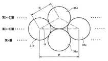
図6は、リールに巻き付けられた超砥粒ワイヤソーの外形を表した模式図である。図6を参照して、第n層に巻き付けられた超砥粒ワイヤソー31aの上から、第(n+1)層に超砥粒ワイヤソー31bおよび31cが巻き付けられ、第(n+2)層に超砥粒ワイヤソー31dが巻き付けられた状態が示されている。これらの超砥粒ワイヤソーは、P=(31/2)DとなるピッチPで巻き付けられている。FIG. 6 is a schematic view showing the outer shape of a superabrasive wire saw wound around a reel. Referring to FIG. 6, superabrasive wire saws 31b and 31c are wound around (n + 1) th layer from above superabrasive wire saw 31a wound around nth layer, and superabrasive wire saw is wound around (n + 2) th layer. A state where 31d is wound is shown. These superabrasive wire saws are wound at a pitch P such that P = (31/2 ) D.
この場合、図中の角度αは30°となり、第(n+2)層に巻き付けられた超砥粒ワイヤソー31dは、第(n+1)層に巻き付けられた超砥粒ワイヤソー31bおよび31cのみならず、第n層に巻き付けられた超砥粒ワイヤソー31aに接触した状態となる。このような接触によって、超砥粒ワイヤソー31aの結合材12が損傷するおそれは増大する。また、P>(31/2)Dの関係を満たすピッチPで超砥粒ワイヤソーが巻き付けられている場合、超砥粒ワイヤソー31dは、超砥粒ワイヤソー31aにのみ接触する。この場合、超砥粒ワイヤソーの巻き付けられた状態が不安定となり、巻き付けピッチが変動するおそれが生じる。In this case, the angle α in the figure is 30 °, and the superabrasive wire saw 31d wound around the (n + 2) th layer is not limited to the superabrasive wire saws 31b and 31c wound around the (n + 1) th layer. It will be in the state which contacted the superabrasive wire saw 31a wound by the n layer. Such contact increases the risk of damaging the
したがって、本実施の形態における超砥粒ワイヤソー巻き付け構造によれば、結合材12の損傷および超砥粒13の欠落をさらに軽減できるとともに、巻き乱れのない状態で超砥粒ワイヤソー10をリール1に巻き付けることができる。 Therefore, according to the superabrasive wire saw winding structure in the present embodiment, the damage of the
(実施の形態3)
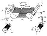
図7は、この発明の実施の形態3における超砥粒ワイヤソー切断装置を示す斜視図である。図7を参照して、超砥粒ワイヤソー切断装置51は、加工物55との間で超砥粒ワイヤソー10を繰り出したり、回収したりする超砥粒ワイヤソー供給部57を備える。超砥粒ワイヤソー供給部57には、実施の形態1または2における超砥粒ワイヤソー巻き付け構造を用いて超砥粒ワイヤソー10が巻き付けられたリール1が設けられている。リール1は、加工物55に対して両側に2つ配置されており、それぞれモーターの回転軸に取り付けられている。(Embodiment 3)
FIG. 7 is a perspective view showing a superabrasive wire saw cutting apparatus according to Embodiment 3 of the present invention. Referring to FIG. 7, superabrasive wire saw cutting
超砥粒ワイヤソー切断装置51は、さらに、超砥粒ワイヤソー10を案内する複数のガイドローラー52および53と、加工物55の下方に位置し、所定の間隔を隔てて配置された2つのメインローラー56と、メインローラー56の近傍に設けられた2つの切削液ノズル54とを備える。メインローラー56の外周面には、加工物55の切断寸法に応じて溝が設けられている。2つのリール1に両端が巻き付けられた超砥粒ワイヤソー10は、その溝に案内されながら、2つのメインローラー56の間で張架されている。ガイドローラー52は、所定の方向に往復運動可能に設けられている。 The superabrasive wire saw cutting
超砥粒ワイヤソー切断装置51を用いて加工物55を切断する場合、リール1が接続されたモーターを正反転させ、超砥粒ワイヤソー10を2つのリール1の間で往復運動させる。このとき、ガイドローラー52を図5中に示すトラバーサ24と同様に往復運動させてもよい。これにより、超砥粒ワイヤソー切断装置51を用いた切断加工時においても、超砥粒ワイヤソー10が所定のピッチPでリール1に巻き付けられ、実施の形態1または2に記載の効果と同様の効果を奏することができる。 When the
続いて、2つのメインローラー56の間で移動する多数本の超砥粒ワイヤソー10に向けて、加工物55を押し付ける。これにより、加工物55を多数枚に切断加工することができる。この際、メインローラー56の外周面に形成された溝と加工物55には、切削液ノズル54から切削液が供給される。この切削液は、切断加工時の摩擦を低減し、冷却を促進する役割を果たす。なお、超砥粒ワイヤソー10が所定のピッチPで巻き付けられるようにガイドローラー52を往復移動させた場合には、超砥粒ワイヤソー10がリール1に巻き付けられた状態で、超砥粒ワイヤソー10の隙間に切断加工時に供給された切削液が介在する。このため、切削液による上述の効果を特に有効に得られるものと考えられる。 Subsequently, the
このように構成された超砥粒ワイヤソー切断装置によれば、所定のピッチPで巻き付けられた超砥粒ワイヤソー10を用いているため、超砥粒ワイヤソー10を再びリール1から繰り出す際にも結合材12が損傷したり超砥粒13が欠落したりすることがない。このため、加工物55を優れた切れ味で切断することができ、超砥粒ワイヤソー10の寿命を延ばすことができる。また、超砥粒ワイヤソー10が所定のピッチPで巻き付けられるようにガイドローラー52を往復移動させた場合には、切断加工の継続中においても、結合材12が損傷したり超砥粒13が欠落することを軽減できる。 According to the superabrasive wire saw cutting device configured as described above, since the superabrasive wire saw 10 wound at a predetermined pitch P is used, the superabrasive wire saw 10 is also coupled when the superabrasive wire saw 10 is fed out of the
本発明による超砥粒ワイヤソー巻き付け構造および巻き付け方法の評価を行なうため、以下に説明する実施例および比較例を実施した。 In order to evaluate the superabrasive wire saw winding structure and winding method according to the present invention, the following examples and comparative examples were implemented.
(実施例1)
図7中の超砥粒ワイヤソー切断装置51を利用して、超砥粒ワイヤソー10の巻き付けピッチPが、結合材12の損傷および超砥粒13の欠落にどのような影響を与えるかを調査する試験を行なった。超砥粒ワイヤソー10の芯線11として、平均直径d1が0.18mmのピアノ線を使用した。また、超砥粒13として、平均直径d2が42μmのダイヤモンド砥粒を使用し、結合材12としてフェノール樹脂を使用した。超砥粒ワイヤソー10の平均直径Dは、0.25mmであった。Example 1
Using the superabrasive wire saw cutting
以下の試験条件で、超砥粒ワイヤソー10を2つのリール1の間で繰り返し往復走行させる繰り出し試験を行なった。 A feeding test in which the superabrasive wire saw 10 was repeatedly reciprocated between the two
「試験条件」
超砥粒ワイヤソー速度;800m/min
巻き付け張力T;9.8N
巻き付けピッチP;0.4mm(D<P<2D)
切削液;水溶性切削液
繰り出しサイクル(1往復を1サイクルとする);212サイクル
試験後、2つのメインローラー56の間に張架されている長さ約82mの超砥粒ワイヤソー10を顕微鏡を用いて観察し、結合材12の累積剥離長さおよび超砥粒13の欠落の有無を調査した。結果、結合材12の累積剥離長さは、50mmであり、超砥粒13の欠落はほとんど認められなかった。"Test conditions"
Super abrasive wire saw speed: 800 m / min
Winding tension T: 9.8N
Winding pitch P: 0.4 mm (D <P <2D)
Cutting fluid; water-soluble cutting fluid feed cycle (one reciprocation is one cycle); 212 cycles After the test, the superabrasive wire saw 10 having a length of about 82 m stretched between the two
(比較例1)
実施例1と同一仕様の超砥粒ワイヤソー10を用い、実施例1の試験条件に倣って繰り出し試験を行なった。但し、試験条件のうち巻き付けピッチPのみを0.2mm(P<D)とした。試験後、実施例1と同様に超砥粒ワイヤソー10を観察した結果、結合材12の累積剥離長さは、250mmであり、超砥粒13の欠落が確認された。(Comparative Example 1)
Using a superabrasive wire saw 10 having the same specifications as in Example 1, a feeding test was conducted in accordance with the test conditions of Example 1. However, among the test conditions, only the winding pitch P was set to 0.2 mm (P <D). After the test, the superabrasive wire saw 10 was observed in the same manner as in Example 1. As a result, the cumulative peel length of the
(比較例2)
実施例1と同一仕様の超砥粒ワイヤソー10を用い、実施例1の試験条件に倣って繰り出し試験を行なった。但し、試験条件のうち巻き付けピッチPのみを0.6mm(P>2D)とした。試験後、実施例1と同様に超砥粒ワイヤソー10を観察した結果、結合材12の累積剥離長さは、280mmであり、超砥粒13の欠落が確認された。(Comparative Example 2)
Using a superabrasive wire saw 10 having the same specifications as in Example 1, a feeding test was conducted in accordance with the test conditions of Example 1. However, among the test conditions, only the winding pitch P was set to 0.6 mm (P> 2D). After the test, the superabrasive wire saw 10 was observed in the same manner as in Example 1. As a result, the cumulative peel length of the
(実施例2)
次に、超砥粒ワイヤソー10の巻き付け張力Tの変化によりどのような影響があるかを調査するため、実施例1と同一仕様の超砥粒ワイヤソー10を用い、以下の試験条件で繰り出し試験を行なった。なお、予め超砥粒ワイヤソー10に引っ張り試験を実施した結果、超砥粒ワイヤソー10の破断強度は78Nであった。(Example 2)
Next, in order to investigate what kind of influence is caused by the change in the winding tension T of the superabrasive wire saw 10, using the superabrasive wire saw 10 having the same specifications as in Example 1, a feeding test was performed under the following test conditions. I did it. As a result of conducting a tensile test on the superabrasive wire saw 10 in advance, the breaking strength of the superabrasive wire saw 10 was 78N.
「試験条件」
超砥粒ワイヤソー速度;800m/min
巻き付け張力T;9.8N(超砥粒ワイヤソー10の破断強度の12.6%)
巻き付けピッチP;0.4mm(D<P<2D)
切削液;水溶性切削液
繰り出しサイクル;424サイクル
試験後、実施例1と同様に超砥粒ワイヤソー10を観察した結果、結合材12の累積剥離長さは、350mmであった。"Test conditions"
Super abrasive wire saw speed: 800 m / min
Winding tension T: 9.8 N (12.6% of breaking strength of superabrasive wire saw 10)
Winding pitch P: 0.4 mm (D <P <2D)
Cutting fluid; water-soluble cutting fluid feeding cycle; 424 cycles After the test, the superabrasive wire saw 10 was observed in the same manner as in Example 1. As a result, the cumulative peel length of the
(実施例3)
実施例1と同一仕様の超砥粒ワイヤソー10を用い、実施例2の試験条件に倣って繰り出し試験を行なった。但し、試験条件のうち巻き付け張力Tのみを25.7N(超砥粒ワイヤソー10の破断強度の33%)とした。試験後、実施例1と同様に超砥粒ワイヤソー10を観察した結果、結合材12の累積剥離長さは、2300mmであった。(Example 3)
Using a superabrasive wire saw 10 having the same specifications as in Example 1, a payout test was conducted following the test conditions in Example 2. However, of the test conditions, only the winding tension T was 25.7 N (33% of the breaking strength of the superabrasive wire saw 10). After the test, the superabrasive wire saw 10 was observed in the same manner as in Example 1. As a result, the cumulative peel length of the
(実施例4)
実施例1と同一仕様の超砥粒ワイヤソー10を用い、実施例2の試験条件に倣って繰り出し試験を行なった。但し、試験条件のうち巻き付け張力Tのみを29.4N(超砥粒ワイヤソー10の破断強度の37.7%)とした。試験後、実施例1と同様に超砥粒ワイヤソー10を観察した結果、結合材12の累積剥離長さは、4120mmであった。Example 4
Using a superabrasive wire saw 10 having the same specifications as in Example 1, a payout test was conducted following the test conditions in Example 2. However, among the test conditions, only the winding tension T was 29.4 N (37.7% of the breaking strength of the superabrasive wire saw 10). After the test, the superabrasive wire saw 10 was observed in the same manner as in Example 1. As a result, the cumulative peel length of the
(比較例3)
実施例1と同一仕様の超砥粒ワイヤソー10を用い、実施例2の試験条件に倣って繰り出し試験を行なった。但し、試験条件のうち巻き付け張力Tのみを39.2N(超砥粒ワイヤソー10の破断強度の52%)とした。試験後、実施例1と同様に超砥粒ワイヤソー10を観察した結果、結合材12の累積剥離長さは、6530mmであった。(Comparative Example 3)
Using a superabrasive wire saw 10 having the same specifications as in Example 1, a payout test was conducted following the test conditions in Example 2. However, only the winding tension T among the test conditions was 39.2 N (52% of the breaking strength of the superabrasive wire saw 10). After the test, the superabrasive wire saw 10 was observed in the same manner as in Example 1. As a result, the cumulative peel length of the
(比較例4)
実施例1と同一仕様の超砥粒ワイヤソー10を用い、実施例2の試験条件に倣った繰り出し試験を試みた。但し、試験条件のうち巻き付け張力Tのみを3N(超砥粒ワイヤソー10の破断強度の3.8%)とした。しかしながら、この場合、リール1に超砥粒ワイヤソー10を巻き付ける際に、巻き緩みが発生し、試験を実施することができなかった。(Comparative Example 4)
Using a superabrasive wire saw 10 having the same specifications as in Example 1, an extension test was attempted in accordance with the test conditions of Example 2. However, of the test conditions, only the winding tension T was 3N (3.8% of the breaking strength of the superabrasive wire saw 10). However, in this case, when the superabrasive wire saw 10 was wound around the
今回開示された実施の形態および実施例はすべての点で例示であって制限的なものではないと考えられるべきである。本発明の範囲は上記した説明ではなくて特許請求の範囲によって示され、特許請求の範囲と均等の意味および範囲内でのすべての変更が含まれることが意図される。 It should be understood that the embodiments and examples disclosed herein are illustrative and non-restrictive in every respect. The scope of the present invention is defined by the terms of the claims, rather than the description above, and is intended to include any modifications within the scope and meaning equivalent to the terms of the claims.
1 リール、2 外周面、3 一方端、4 他方端、10,31a,31b,31c,31d 超砥粒ワイヤソー、11 芯線、11a 表面、12 結合材、13 超砥粒、51 超砥粒ワイヤソー切断装置、57 超砥粒ワイヤソー供給部。 1 reel, 2 outer peripheral surface, 3 one end, 4 other end, 10, 31a, 31b, 31c, 31d superabrasive wire saw, 11 core wire, 11a surface, 12 binder, 13 superabrasive, 51 superabrasive wire saw Equipment, 57 Superabrasive wire saw supply unit.
Claims (6)
Translated fromJapanese一方端と他方端とを有する外周面を含み、加工物に向けて順次繰り出される前記超砥粒ワイヤソーが、前記一方端と前記他方端との間で往復しながら前記外周面に多層に巻き付けられるリール部とを備え、
前記超砥粒ワイヤソーが前記一方端と前記他方端との間で前記外周面に巻き付けられるピッチPは、1.1D<P<(31/2)Dの関係を満たす、超砥粒ワイヤソー巻き付け構造。A superabrasive wire saw formed with an average diameter D, including a core wire, a binding material surrounding the surface of the core wire, and a plurality of superabrasive grains fixed to the surface of the core wire by the binding material;
The superabrasive wire saw that includes an outer peripheral surface having one end and the other end and is sequentially fed toward the workpiece is wound around the outer peripheral surface in a multilayer manner while reciprocating between the one end and the other end. With reel part,
The pitch P at which the superabrasive wire saw is wound around the outer peripheral surface between the one end and the other end satisfies the relationship of1.1D <P <(31/2) D. Construction.
前記超砥粒ワイヤソーを前記一方端と前記他方端との間で往復させながら前記外周面に多層に巻き付ける工程とを備え、
前記超砥粒ワイヤソーを巻き付ける工程は、前記一方端と前記他方端との間で前記超砥粒ワイヤソーを巻き付けるピッチPが、1.1D<P<(31/2)Dの関係を満たすように前記超砥粒ワイヤソーを巻き付ける工程を含む、超砥粒ワイヤソーの巻き付け方法。A superabrasive wire saw having an average diameter D, a core wire, a binding material surrounding the surface of the core wire, and a plurality of superabrasive grains fixed to the surface of the core wire by the binding material; Preparing a reel portion including an outer peripheral surface having:
Winding the superabrasive wire saw around the outer peripheral surface while reciprocating between the one end and the other end, and
The step of winding the superabrasive wire saw is such that the pitch P for winding the superabrasive wire saw between the one end and the other end satisfies a relationship of1.1D <P <(31/2) D. A method for winding a superabrasive wire saw, comprising the step of winding the superabrasive wire saw on a wire.
Priority Applications (10)
| Application Number | Priority Date | Filing Date | Title |
|---|---|---|---|
| JP2003429425AJP4411062B2 (en) | 2003-12-25 | 2003-12-25 | Super abrasive wire saw winding structure, super abrasive wire saw cutting device, and super abrasive wire saw winding method |
| RU2006111456ARU2310549C2 (en) | 2003-12-25 | 2004-06-03 | Superabrasive wire saw-winding apparatus, cutting apparatus with superabrasive wire saw, winding method of superabrasive wire saw |
| US10/571,131US7926478B2 (en) | 2003-12-25 | 2004-06-03 | Super abrasive grain wire saw winding structure, super abrasive grain wire saw cutting device, and super abrasive grain wire saw winding method |
| EP20040735988EP1698433B1 (en) | 2003-12-25 | 2004-06-03 | Super abrasive grain wire saw winding structure, super abrasive grain wire saw cutting device, and super abrasive grain wire saw winding method |
| KR1020077025220AKR20070108288A (en) | 2003-12-25 | 2004-06-03 | Cutting processing method |
| CN2004800286624ACN1863643B (en) | 2003-12-25 | 2004-06-03 | Winding method of superabrasive wire saw |
| PCT/JP2004/008092WO2005063440A1 (en) | 2003-12-25 | 2004-06-03 | Super abrasive grain wire saw winding structure, super abrasive grain wire saw cutting device, and super abrasive grain wire saw winding method |
| KR1020067005936AKR20060057016A (en) | 2003-12-25 | 2004-06-03 | Super-Grip Wire Saw Winding Structure, Super-Grip Wire Saw Cutting Machine and Super-Grip Wire Saw |
| TW93116116ATWI272157B (en) | 2003-12-25 | 2004-06-04 | Superabrasive wire saw-wound structure, cutting device with superabrasive wire saw and method of winding superabrasive wire saw |
| MYPI20044008AMY143896A (en) | 2003-12-25 | 2004-09-30 | Superabrasive wire saw-wound structure, cutting device with superabrasive wire saw and method of winding superabrasive wire saw |
Applications Claiming Priority (1)
| Application Number | Priority Date | Filing Date | Title |
|---|---|---|---|
| JP2003429425AJP4411062B2 (en) | 2003-12-25 | 2003-12-25 | Super abrasive wire saw winding structure, super abrasive wire saw cutting device, and super abrasive wire saw winding method |
Publications (2)
| Publication Number | Publication Date |
|---|---|
| JP2005186202A JP2005186202A (en) | 2005-07-14 |
| JP4411062B2true JP4411062B2 (en) | 2010-02-10 |
Family
ID=34736304
Family Applications (1)
| Application Number | Title | Priority Date | Filing Date |
|---|---|---|---|
| JP2003429425AExpired - Fee RelatedJP4411062B2 (en) | 2003-12-25 | 2003-12-25 | Super abrasive wire saw winding structure, super abrasive wire saw cutting device, and super abrasive wire saw winding method |
Country Status (9)
| Country | Link |
|---|---|
| US (1) | US7926478B2 (en) |
| EP (1) | EP1698433B1 (en) |
| JP (1) | JP4411062B2 (en) |
| KR (2) | KR20070108288A (en) |
| CN (1) | CN1863643B (en) |
| MY (1) | MY143896A (en) |
| RU (1) | RU2310549C2 (en) |
| TW (1) | TWI272157B (en) |
| WO (1) | WO2005063440A1 (en) |
Families Citing this family (58)
| Publication number | Priority date | Publication date | Assignee | Title |
|---|---|---|---|---|
| JP2007111823A (en)* | 2005-10-20 | 2007-05-10 | Toko Kikai Seisakusho:Kk | Wire-type cutting device |
| US8945316B2 (en)* | 2008-02-07 | 2015-02-03 | Fontana Technology | Method for shaping and slicing ingots using an aqueous phosphate solution |
| US8286625B2 (en)* | 2008-05-27 | 2012-10-16 | Jenkins Nicholas J T | Underwater diamond wire saw assembly |
| WO2010058597A1 (en)* | 2008-11-21 | 2010-05-27 | 古河電気工業株式会社 | Wire body take-up device and wire body take-up method |
| EP2218532B1 (en)* | 2009-02-17 | 2013-10-30 | Applied Materials, Inc. | Wire saw device and method for operating same |
| JP5527987B2 (en)* | 2009-02-25 | 2014-06-25 | 京セラ株式会社 | Wire saw device and substrate manufacturing method |
| US8490658B2 (en) | 2009-02-26 | 2013-07-23 | Saint-Gobain Abrasives, Inc. | Automatic winding of wire field in wire slicing machine |
| KR20120016619A (en)* | 2009-04-29 | 2012-02-24 | 엔브이 베카에르트 에스에이 | Fixed abrasive sawing wire with rough interface between core and outer sheath |
| KR20120036906A (en)* | 2009-06-05 | 2012-04-18 | 어플라이드 머티어리얼스, 인코포레이티드 | Polishing wire manufacturing method and apparatus |
| MX2012001810A (en) | 2009-08-14 | 2012-06-01 | Saint Gobain Abrasives Inc | ABRASIVE ITEMS THAT INCLUDE ABRASIVE PARTICLES UNITED TO A LONG BODY. |
| KR101433750B1 (en) | 2009-08-14 | 2014-08-27 | 생-고뱅 어브레이시브즈, 인코포레이티드 | Abrasive articles including abrasive particles bonded to an elongated body, and methods of forming thereof |
| US8881716B2 (en)* | 2010-02-08 | 2014-11-11 | Toyo Advanced Technologies Co., Ltd. | Wire saw with tension detecting means and guide roller speed control |
| TWI488710B (en)* | 2010-02-11 | 2015-06-21 | Toyo Advanced Tech Co | Wire saws |
| TWI461249B (en)* | 2010-04-27 | 2014-11-21 | Kinik Co | Wire saw and method for fabricating the same |
| WO2011138192A2 (en)* | 2010-05-04 | 2011-11-10 | Nv Bekaert Sa | Fixed abrasive sawing wire with removable protective coating |
| MY155751A (en)* | 2010-06-15 | 2015-11-30 | Nippon Steel Corp | Saw wire |
| EP2643118B1 (en)* | 2010-11-22 | 2017-05-17 | Bekaert Binjiang Steel Cord Co., Ltd. | A structured sawing wire |
| GB2540053B (en)* | 2010-11-22 | 2017-06-07 | Belron Hungary Kft - Zug Branch | Apparatus and method for cutting out a vehicle glazing panel |
| JP5678653B2 (en)* | 2010-12-28 | 2015-03-04 | 三菱化学株式会社 | Method for producing hexagonal semiconductor plate crystal |
| TWI466990B (en) | 2010-12-30 | 2015-01-01 | Saint Gobain Abrasives Inc | Abrasive article and forming method |
| WO2012171754A1 (en) | 2011-06-17 | 2012-12-20 | Nv Bekaert Sa | Spool for winding fine wire at high tension with flexible core |
| JP5956567B2 (en) | 2011-06-17 | 2016-07-27 | ナムローゼ・フェンノートシャップ・ベーカート・ソシエテ・アノニムN V Bekaert Societe Anonyme | A spool that has a flexible support inside and is configured to wind thin wires with high tension |
| JP5155428B2 (en)* | 2011-07-15 | 2013-03-06 | コマツNtc株式会社 | Wire saw |
| JP5150756B2 (en)* | 2011-07-29 | 2013-02-27 | コマツNtc株式会社 | Wire saw |
| DE102011082366B3 (en)* | 2011-09-08 | 2013-02-28 | Siltronic Ag | Single-layer winding of saw wire with fixed cutting grain for wire saws for separating slices from a workpiece |
| JP5733120B2 (en)* | 2011-09-09 | 2015-06-10 | 住友電気工業株式会社 | Saw wire and method for producing group III nitride crystal substrate using the same |
| CN102320496B (en)* | 2011-09-12 | 2014-05-28 | 河北省电力建设调整试验所 | Wire winding device for tidying experimental test conducting wire |
| CN107263340A (en) | 2011-09-16 | 2017-10-20 | 圣戈班磨料磨具有限公司 | abrasive article and forming method |
| WO2013049204A2 (en) | 2011-09-29 | 2013-04-04 | Saint-Gobain Abrasives, Inc. | Abrasive articles including abrasive particles bonded to an elongated substrate body having a barrier layer, and methods of forming thereof |
| JP4999133B1 (en)* | 2011-09-30 | 2012-08-15 | 古河電気工業株式会社 | Wire rod winding bobbin, wire rod winding method, and wire rod winding device |
| EP2583777A1 (en)* | 2011-10-22 | 2013-04-24 | Applied Materials Switzerland Sàrl | Clamping assembly for a wire guide of a wire saw |
| US20130144421A1 (en)* | 2011-12-01 | 2013-06-06 | Memc Electronic Materials, Spa | Systems For Controlling Temperature Of Bearings In A Wire Saw |
| JP2013220482A (en)* | 2012-04-13 | 2013-10-28 | Tokyo Seiko Co Ltd | Wire-type cutting device |
| TW201404527A (en) | 2012-06-29 | 2014-02-01 | Saint Gobain Abrasives Inc | Abrasive article and method of forming |
| TWI474889B (en) | 2012-06-29 | 2015-03-01 | Saint Gobain Abrasives Inc | Abrasive article and method of forming |
| TWI483803B (en)* | 2012-06-29 | 2015-05-11 | Saint Gobain Abrasives Inc | Method of conducting a cutting operation on a workpiece |
| TWI477343B (en) | 2012-06-29 | 2015-03-21 | Saint Gobain Abrasives Inc | Abrasive article and method of forming |
| TW201402274A (en)* | 2012-06-29 | 2014-01-16 | Saint Gobain Abrasives Inc | Abrasive article and method of forming |
| US9597819B2 (en)* | 2012-09-03 | 2017-03-21 | Hitachi Metals, Ltd. | Method for cutting high-hardness material by multi-wire saw |
| CN106862663B (en)* | 2012-12-04 | 2019-01-04 | 梅耶博格(瑞士)公司 | Wire management system |
| TW201441355A (en)* | 2013-04-19 | 2014-11-01 | Saint Gobain Abrasives Inc | Abrasive article and method of forming |
| JP6318637B2 (en)* | 2014-01-17 | 2018-05-09 | 日立金属株式会社 | Cutting method of high hardness material with multi-wire saw |
| TWI621505B (en) | 2015-06-29 | 2018-04-21 | 聖高拜磨料有限公司 | Abrasive article and forming method |
| CN107921603B (en)* | 2015-08-31 | 2019-05-31 | 小松Ntc株式会社 | The driving method of wire saw and wire saw |
| JP6402700B2 (en)* | 2015-10-20 | 2018-10-10 | 信越半導体株式会社 | Work cutting method and wire saw |
| JP6270796B2 (en)* | 2015-10-28 | 2018-01-31 | 株式会社リード | Fixed abrasive wire saw and fixed abrasive wire dressing method |
| JP2017121686A (en)* | 2016-01-07 | 2017-07-13 | 信越半導体株式会社 | Cutting method of ingot |
| JP6589735B2 (en)* | 2016-04-21 | 2019-10-16 | 信越半導体株式会社 | Manufacturing method of wire saw device |
| JP2018058147A (en)* | 2016-10-04 | 2018-04-12 | 株式会社タカトリ | Wire saw and wire winding method of wire saw |
| JP6908386B2 (en)* | 2017-01-27 | 2021-07-28 | コマツNtc株式会社 | Method of cutting workpieces with wire saws and wires |
| DE102017202314A1 (en)* | 2017-02-14 | 2018-08-16 | Siltronic Ag | Wire saw, wire guide roller, and method of simultaneously separating a plurality of disks from a rod |
| WO2019008530A1 (en)* | 2017-07-07 | 2019-01-10 | Meyer Burger (Switzerland) Ag | Method of winding a cutting wire |
| DE102018221921A1 (en)* | 2018-12-17 | 2020-06-18 | Siltronic Ag | Method for manufacturing semiconductor wafers using a wire saw |
| DE102019207719A1 (en) | 2019-05-27 | 2020-12-03 | Siltronic Ag | Method for severing a multiplicity of wafers from workpieces during a number of severing operations by means of a wire saw and semiconductor wafer made of monocrystalline silicon |
| US10799967B1 (en) | 2019-08-27 | 2020-10-13 | Nicholas J. T. Jenkins | Diamond wire saw apparatus |
| EP3858569A1 (en) | 2020-01-28 | 2021-08-04 | Siltronic AG | Method for separating a plurality of slices from workpieces by means of a wire saw during a sequence of separation operations |
| CN112873070B (en)* | 2021-01-21 | 2022-07-05 | 泉州众志新材料科技有限公司 | Ceramic tile chamfering abrasive disc and production method thereof |
| CN114606465B (en)* | 2022-01-27 | 2024-05-17 | 深圳富联智能制造产业创新中心有限公司 | Method for preparing cutting line and cutting line |
Family Cites Families (39)
| Publication number | Priority date | Publication date | Assignee | Title |
|---|---|---|---|---|
| US4015931A (en)* | 1975-09-29 | 1977-04-05 | Engelhard Minerals & Chemicals Corporation | Bonded-abrasive wire saw |
| US4110902A (en)* | 1975-12-22 | 1978-09-05 | Hitachi, Ltd. | Method for manufacturing a magnetic head for video signal |
| SU935156A1 (en)* | 1980-06-09 | 1982-06-15 | Производственное Объединение "Ждановтяжмаш" | Machine for stripping and winding wire |
| JPH01295758A (en)* | 1988-05-19 | 1989-11-29 | Osaka Titanium Co Ltd | Slicing method and wire saw machine |
| JP2673544B2 (en)* | 1988-06-14 | 1997-11-05 | 株式会社日平トヤマ | Cutting method for brittle materials |
| JP2827512B2 (en) | 1990-12-12 | 1998-11-25 | 三菱マテリアル株式会社 | Bonding wire winding, bonding wire winding method and winding device therefor |
| JPH0531865U (en)* | 1991-10-08 | 1993-04-27 | 株式会社日平トヤマ | Disconnecting device for cutting wire |
| JPH0735456U (en)* | 1993-12-06 | 1995-07-04 | 日立電線株式会社 | Bobbin for aligned winding |
| JPH08126953A (en) | 1994-10-28 | 1996-05-21 | Shin Etsu Handotai Co Ltd | Wire saw and manufacture of wire |
| JP2870452B2 (en)* | 1995-05-31 | 1999-03-17 | 信越半導体株式会社 | Wire saw |
| JP2885270B2 (en)* | 1995-06-01 | 1999-04-19 | 信越半導体株式会社 | Wire saw device and work cutting method |
| US5564409A (en)* | 1995-06-06 | 1996-10-15 | Corning Incorporated | Apparatus and method for wire cutting glass-ceramic wafers |
| JP3107143B2 (en)* | 1995-07-14 | 2000-11-06 | 株式会社東京精密 | Wire traverse device for wire saw |
| JPH0938854A (en)* | 1995-07-31 | 1997-02-10 | Sharp Corp | Multi wire saw wire feeder |
| JPH09155631A (en)* | 1995-12-04 | 1997-06-17 | Asahi Daiyamondo Kogyo Kk | Diamond wire saw and manufacturing method thereof |
| JP3141767B2 (en)* | 1996-01-19 | 2001-03-05 | トヨタ自動車株式会社 | Evaporative fuel treatment system for internal combustion engine |
| CZ283541B6 (en)* | 1996-03-06 | 1998-04-15 | Trimex Tesla, S.R.O. | Process of cutting ingots from hard materials to plates and a saw for making the same |
| EP0803336B1 (en)* | 1996-04-27 | 2003-07-02 | Nippei Toyama Corporation | Wire saw and work slicing method |
| WO1998035784A1 (en)* | 1997-02-14 | 1998-08-20 | Sumitomo Electric Industries, Ltd. | Wire-saw and its manufacturing method |
| JPH11198020A (en) | 1997-11-04 | 1999-07-27 | Tokyo Seimitsu Co Ltd | Fixed abrasive grain wire saw |
| JP3770579B2 (en) | 1998-04-28 | 2006-04-26 | 株式会社アライドマテリアル | Cutting method with wire saw |
| JP2000061803A (en)* | 1998-08-27 | 2000-02-29 | Hitachi Cable Ltd | Saw wire assembly, cutting method using the same and apparatus therefor |
| TW383249B (en)* | 1998-09-01 | 2000-03-01 | Sumitomo Spec Metals | Cutting method for rare earth alloy by annular saw and manufacturing for rare earth alloy board |
| EP1065017A4 (en)* | 1998-11-02 | 2001-11-14 | Ngk Insulators Ltd | Method and device for three-dimensional arrangement of wire and method of manufacturing conductive material |
| JP3256503B2 (en)* | 1998-11-05 | 2002-02-12 | 日本碍子株式会社 | Cutting equipment for ceramic green body products |
| ES2247964T3 (en)* | 1999-02-04 | 2006-03-16 | Ricoh Company, Ltd. | WIRE SAW WITH ABRASIVE WIRE AND PROCEDURE FOR MANUFACTURING THE ABRASIVE WIRE. |
| JP2000349120A (en) | 1999-06-07 | 2000-12-15 | Tanaka Electronics Ind Co Ltd | Winding method of bonding wire for semiconductor device |
| JP2001039682A (en) | 1999-07-30 | 2001-02-13 | Shimadzu Corp | Winch device |
| CN1175961C (en)* | 1999-09-17 | 2004-11-17 | 株式会社新王磁材 | Method and device for cutting rare-earth alloy |
| JP2001225258A (en)* | 2000-02-16 | 2001-08-21 | Asaoka Kk | Wire saw and its manufacture |
| US6352071B1 (en)* | 2000-06-20 | 2002-03-05 | Seh America, Inc. | Apparatus and method for reducing bow and warp in silicon wafers sliced by a wire saw |
| JP2002018517A (en) | 2000-07-07 | 2002-01-22 | Hitachi Cable Ltd | Wire winding device |
| CN1228162C (en) | 2000-11-24 | 2005-11-23 | 株式会社新王磁材 | Method for cutting off rare-earth alloy, process for preparing rare-earth magnet and fret saw |
| JP2002370152A (en)* | 2001-06-12 | 2002-12-24 | Japan Fine Steel Co Ltd | Winding reel for saw wire |
| JP4961647B2 (en) | 2001-09-06 | 2012-06-27 | 日立金属株式会社 | Rare earth alloy cutting method and rare earth magnet manufacturing method |
| US6945242B2 (en)* | 2001-10-17 | 2005-09-20 | Neomax Co., Ltd. | Cutting method using wire saw, wire saw device, and method of manufacturing rare-earth magnet |
| US7025054B2 (en)* | 2002-03-01 | 2006-04-11 | Neomax Co., Ltd. | Method of cutting rare-earth alloy |
| US7089925B1 (en)* | 2004-08-18 | 2006-08-15 | Kinik Company | Reciprocating wire saw for cutting hard materials |
| JP4820108B2 (en)* | 2005-04-25 | 2011-11-24 | コマツNtc株式会社 | Semiconductor wafer manufacturing method, workpiece slicing method, and wire saw used therefor |
- 2003
- 2003-12-25JPJP2003429425Apatent/JP4411062B2/ennot_activeExpired - Fee Related
- 2004
- 2004-06-03RURU2006111456Apatent/RU2310549C2/ennot_activeIP Right Cessation
- 2004-06-03USUS10/571,131patent/US7926478B2/ennot_activeExpired - Fee Related
- 2004-06-03KRKR1020077025220Apatent/KR20070108288A/ennot_activeCeased
- 2004-06-03KRKR1020067005936Apatent/KR20060057016A/ennot_activeCeased
- 2004-06-03EPEP20040735988patent/EP1698433B1/ennot_activeExpired - Lifetime
- 2004-06-03CNCN2004800286624Apatent/CN1863643B/ennot_activeExpired - Fee Related
- 2004-06-03WOPCT/JP2004/008092patent/WO2005063440A1/enactiveApplication Filing
- 2004-06-04TWTW93116116Apatent/TWI272157B/ennot_activeIP Right Cessation
- 2004-09-30MYMYPI20044008Apatent/MY143896A/enunknown
Also Published As
| Publication number | Publication date |
|---|---|
| TWI272157B (en) | 2007-02-01 |
| JP2005186202A (en) | 2005-07-14 |
| RU2006111456A (en) | 2006-08-27 |
| TW200524707A (en) | 2005-08-01 |
| EP1698433A1 (en) | 2006-09-06 |
| US7926478B2 (en) | 2011-04-19 |
| US20070023027A1 (en) | 2007-02-01 |
| KR20070108288A (en) | 2007-11-08 |
| WO2005063440A1 (en) | 2005-07-14 |
| CN1863643A (en) | 2006-11-15 |
| EP1698433B1 (en) | 2013-01-23 |
| WO2005063440A9 (en) | 2005-09-15 |
| EP1698433A4 (en) | 2009-04-15 |
| MY143896A (en) | 2011-07-29 |
| RU2310549C2 (en) | 2007-11-20 |
| CN1863643B (en) | 2012-12-26 |
| KR20060057016A (en) | 2006-05-25 |
Similar Documents
| Publication | Publication Date | Title |
|---|---|---|
| JP4411062B2 (en) | Super abrasive wire saw winding structure, super abrasive wire saw cutting device, and super abrasive wire saw winding method | |
| JP2007237628A (en) | Method and apparatus for cutting single crystal sapphire substrate | |
| JP2007237627A (en) | Method and apparatus for cutting single crystal sapphire substrate | |
| JP2006123055A (en) | Cutting method of workpiece with superabrasive wire saw and workpiece cut with superabrasive wire saw | |
| JP4072512B2 (en) | Calculation method of superabrasive ratio of superabrasive wire saw | |
| JP2002036091A (en) | Superabrasive wire saw and manufacturing method thereof | |
| JP2006007387A (en) | Super abrasive wire saw | |
| US10029392B2 (en) | Method for slicing workpiece | |
| KR102823917B1 (en) | Work cutting method and wire saw | |
| JP2000288902A (en) | Wire with fixed abrasive grains and fixed abrasive grain wire saw | |
| JP5958430B2 (en) | Work cutting method and wire saw | |
| JP2008006584A (en) | Cutting method using superabrasive wire saw | |
| JP5876388B2 (en) | Workpiece cutting method | |
| JP2011079106A (en) | Method of cutting workpiece by fixed abrasive grain wire saw | |
| CN111670088B (en) | Method for cutting workpiece and wire saw | |
| JP2014181125A (en) | Reel for winding superabrasive wire saw | |
| JP4014439B2 (en) | Wire saw pulley and wire saw using the same | |
| JP5311964B2 (en) | Wire saw equipment | |
| JP5945967B2 (en) | Work cutting method and wire saw | |
| JP2010194677A (en) | Wire saw device and method for manufacturing substrate | |
| JP5991267B2 (en) | Work cutting method and cutting device | |
| JP5962614B2 (en) | Work cutting method and wire saw | |
| JPH1034646A (en) | Wire and method and device for working workpiece using the same |
Legal Events
| Date | Code | Title | Description |
|---|---|---|---|
| A621 | Written request for application examination | Free format text:JAPANESE INTERMEDIATE CODE: A621 Effective date:20060518 | |
| A131 | Notification of reasons for refusal | Free format text:JAPANESE INTERMEDIATE CODE: A131 Effective date:20090901 | |
| A521 | Written amendment | Free format text:JAPANESE INTERMEDIATE CODE: A523 Effective date:20091015 | |
| TRDD | Decision of grant or rejection written | ||
| A01 | Written decision to grant a patent or to grant a registration (utility model) | Free format text:JAPANESE INTERMEDIATE CODE: A01 Effective date:20091110 | |
| A01 | Written decision to grant a patent or to grant a registration (utility model) | Free format text:JAPANESE INTERMEDIATE CODE: A01 | |
| A61 | First payment of annual fees (during grant procedure) | Free format text:JAPANESE INTERMEDIATE CODE: A61 Effective date:20091116 | |
| R150 | Certificate of patent or registration of utility model | Free format text:JAPANESE INTERMEDIATE CODE: R150 | |
| FPAY | Renewal fee payment (event date is renewal date of database) | Free format text:PAYMENT UNTIL: 20121120 Year of fee payment:3 | |
| FPAY | Renewal fee payment (event date is renewal date of database) | Free format text:PAYMENT UNTIL: 20121120 Year of fee payment:3 | |
| FPAY | Renewal fee payment (event date is renewal date of database) | Free format text:PAYMENT UNTIL: 20131120 Year of fee payment:4 | |
| R250 | Receipt of annual fees | Free format text:JAPANESE INTERMEDIATE CODE: R250 | |
| R250 | Receipt of annual fees | Free format text:JAPANESE INTERMEDIATE CODE: R250 | |
| R250 | Receipt of annual fees | Free format text:JAPANESE INTERMEDIATE CODE: R250 | |
| R250 | Receipt of annual fees | Free format text:JAPANESE INTERMEDIATE CODE: R250 | |
| LAPS | Cancellation because of no payment of annual fees |