JP4409749B2 - Map display system - Google Patents
Map display systemDownload PDFInfo
- Publication number
- JP4409749B2 JP4409749B2JP2000352508AJP2000352508AJP4409749B2JP 4409749 B2JP4409749 B2JP 4409749B2JP 2000352508 AJP2000352508 AJP 2000352508AJP 2000352508 AJP2000352508 AJP 2000352508AJP 4409749 B2JP4409749 B2JP 4409749B2
- Authority
- JP
- Japan
- Prior art keywords
- mobile terminal
- map
- terminal device
- map data
- display
- Prior art date
- Legal status (The legal status is an assumption and is not a legal conclusion. Google has not performed a legal analysis and makes no representation as to the accuracy of the status listed.)
- Expired - Fee Related
Links
- 230000005540biological transmissionEffects0.000claimsdescription63
- 238000000034methodMethods0.000claimsdescription6
- 238000001514detection methodMethods0.000claims6
- 238000004891communicationMethods0.000description12
- 238000010586diagramMethods0.000description10
- 238000006243chemical reactionMethods0.000description6
- 238000005516engineering processMethods0.000description5
- 230000001174ascending effectEffects0.000description1
- 230000001413cellular effectEffects0.000description1
- 230000000694effectsEffects0.000description1
- 230000006870functionEffects0.000description1
- 230000004044responseEffects0.000description1
Images


Classifications
- G—PHYSICS
- G08—SIGNALLING
- G08G—TRAFFIC CONTROL SYSTEMS
- G08G1/00—Traffic control systems for road vehicles
- G08G1/09—Arrangements for giving variable traffic instructions
- G08G1/0962—Arrangements for giving variable traffic instructions having an indicator mounted inside the vehicle, e.g. giving voice messages
- G08G1/0968—Systems involving transmission of navigation instructions to the vehicle
- G08G1/0969—Systems involving transmission of navigation instructions to the vehicle having a display in the form of a map
Landscapes
- Engineering & Computer Science (AREA)
- Radar, Positioning & Navigation (AREA)
- Remote Sensing (AREA)
- Physics & Mathematics (AREA)
- General Physics & Mathematics (AREA)
- Navigation (AREA)
- Instructional Devices (AREA)
- Traffic Control Systems (AREA)
- Processing Or Creating Images (AREA)
- Digital Computer Display Output (AREA)
- Information Transfer Between Computers (AREA)
Description
Translated fromJapanese【0001】
【発明が属する技術分野】
本発明は、移動端末装置を用いた地図表示システムに関する。
【0002】
【従来の技術】
携帯電話業者或いはその提携業者が提供する情報提供サービスの1つとして携帯電話機の表示画面に地図を表示させることは既に行われている。通常、各地域の地図データを提供するデータサーバが備えられ、携帯電話機のユーザが希望する地域を操作によって指定し、その指定地域の情報がデータサーバに送信され、それに対応する地図データがデータサーバから携帯電話機に無線で送られてきて携帯電話機の表示画面に希望地域の地図が表示される。
【0003】
【発明が解決しようとする課題】
携帯電話機等の移動端末装置を所有するユーザは不慣れな移動先で地図を見る場合が普通であり、このような場合には方角さえ良く分からないことが多い。しかしながら、移動端末装置の表示画面に表示される地図は通常、北を上方にして表示されるので、移動先で北方向が直ちに分からないとユーザにとって表示された地図が分かり辛いという問題があった。
【0004】
そこで、本発明の目的は、移動先の方角と表示地図の向きとの関係が容易に分かるように移動端末装置に地図を表示させることができる地図表示システムを提供することである。
【0005】
【課題を解決するための手段】
本発明の地図表示システムは、移動端末装置とホスト装置との間で通信を行って前記移動端末装置の表示部に地図を表示させる地図表示システムであって、前記ホスト装置は、前記移動端末装置が通路上の第1の領域に存在することを検出する第1端末検出手段と、前記第1端末検出手段によって前記移動端末装置の前記第1の領域における存在が検出されたときに前記第1の領域付近の地図を示す第1地図データを前記移動端末装置に送信する第1送信手段と、前記移動端末装置が前記通路上において前記第1の領域とは通路方向における位置が異なる第2の領域に存在することを検出する検出手段と、前記移動端末装置の前記第2の領域における存在を検出したときに前記第2の領域付近の地図を示す第2地図データを前記移動端末装置に送信する第2送信手段と、を備え、前記移動端末装置は、前記第1送信手段によって送信された第1地図データを受信する受信手段と、前記移動端末装置の方位を検出する方位検出手段と、前記通路における前記移動端末装置の進行方向が表示上向きとなるように前記方位検出手段によって検出された方位に応じて前記受信手段によって受信された地図データを変換し、変換後の地図データが示す地図を前記表示部に表示させる制御手段と、を備え、前記第2送信手段は、前記移動端末装置の前記第1の領域における存在を検出した直後に、前記移動端末装置の前記第2の領域における存在を検出したときには前記第2の領域付近の地図を示す第2地図データの前記移動端末装置への送信を実行しないことを特徴としている。
【0007】
本発明の地図表示方法は、移動端末装置とホスト装置との間で通信を行って前記移動端末装置の表示部に地図を表示させる地図表示方法であって、前記移動端末装置では、前記移動端末装置の方位を検出し、通路における前記移動端末装置の進行方向が表示上向きとなるように検出した方位に応じて受信した地図データを変換し、変換後の地図データが示す地図を前記表示部に表示させ、前記ホスト装置は、前記移動端末装置が通路上の第1の領域に存在することを検出したときには前記第1の領域付近の地図を示す第1地図データを前記移動端末装置に送信し、前記移動端末装置が前記通路上において前記第1の領域とは通路方向における位置が異なる第2の領域に存在することを検出したときには前記第2の領域付近の地図を示す第2地図データを前記移動端末装置に送信する一方、前記移動端末装置の前記第1の領域における存在を検出した直後に、前記移動端末装置の前記第2の領域における存在を検出したときには前記第2地図データの前記移動端末装置への送信を実行しないことを特徴としている。
【0011】
本発明の移動端末装置は、地図を表示するための表示器と、地図データを受信する受信手段と、前記移動端末装置の方位を検出する方位検出手段と、前記方位検出手段によって検出された方位に応じて前記表示部における表示地図が所定の表示向きとなるように前記受信手段によって受信された地図データを変換し、変換後の地図データが示す地図を前記表示部に表示させる制御手段と、を備えた移動端末装置であって、前記制御手段は、前記受信手段によって1のセルに対応する地図データが受信された後に、前記1のセルとは異なるセルに対応する地図データが受信された場合にはその異なるセルに対応する地図データを無視してそれまでの地図表示を継続させることを特徴としている。
【0012】
本発明の移動端末装置は、地図データを受信する受信手段と、受信手段によって受信された地図データが示す地図を表示部に表示させる制御手段と、を備えた移動端末装置であって、制御手段は、受信手段によって1のセルに対応する地図データが受信された後に、1のセルとは異なるセルに対応する地図データが受信された場合にはその異なるセルに対応する地図データを無視してそれまでの地図表示を継続させることを特徴としている。
【0013】
【発明の実施の形態】
以下、本発明の実施例を図面を参照しつつ詳細に説明する。
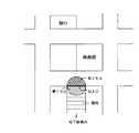
図1は本発明による地図表示システムを示している。この地図表示システムは、ホスト装置1と携帯端末装置2とからなる。ホスト装置1は地下鉄の地上への出入口付近に設置される。ホスト装置1と携帯端末装置2との間においては無線通信が行われる。無線通信技術としてはブルートゥース(Bluetooth)規格に対応した技術が用いられる。
【0014】
ホスト装置1は、図1に示すように、ブルートゥース送受信部11,12と、制御回路13と、記憶装置14とから構成される。ブルートゥース送受信部11,12各々はブルートゥース規格に準拠した送受信部であり、アンテナ11a,12aを有している。アンテナ11a,12aは個別の指向性を有するものである。アンテナ11aによる送受信領域は半円形の第1セルであり、アンテナ12aによる送受信領域は半円形の第2セルであり、互いに異なる領域である。記憶装置14には画像データとしての地図データが記憶されている。ここで用いられる地図データは、地下鉄構内からその出入口へ進む階段の上り方向を地図の向きとした地上の地図と、地下鉄の出入口から階段の下り方向を地図の向きとした地下鉄構内の地図とである。その地図には、道路や通路の他、銀行、ホテル、デパート、一般の商店等の店舗や目印となる建物がその名称と共に示されている。制御回路13は、ブルートゥース送受信部11が携帯端末装置2を含むブルートゥース機器からの信号を受信すると、記憶装置14から地図データを読み出してその地図データをブルートゥース送受信部11に送信させる。
【0015】
携帯端末装置2は携帯電話機として機能を有する移動端末装置である。概略的に構成を示すと、図1に示すように、携帯端末装置2は電話送受信部31と、ブルートゥース送受信部32と、表示部33と、操作部34と、メモリ35と、CPUからなる制御回路36とを備えている。無線電話のための電話送受信部31にはアンテナ31aの他に電話送話用のマイクロホン37及び受話用のスピーカ38が接続されている。ブルートゥース送受信部32はブルートゥース規格に準拠した送受信部である。ブルートゥース送受信部32にはアンテナ32aが接続されている。制御回路36は、電話送受信部31、ブルートゥース送受信部32、表示部33、操作部34及びメモリ35に接続され、携帯端末装置2全体の動作を制御する。
【0016】
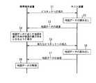
携帯端末装置2を所有するユーザが地下鉄構内から図2に示す階段を移動して第1セルの範囲に入ると、図3に示すように、携帯端末装置2のピコネットへの加入動作が行われる(ステップS1)。ピコネットにおいてホスト装置1はマスターとなり、携帯端末装置2はスレーブとなる。ピコネットへの加入動作の手順についてはブルートゥース規格によって定められているので、ここでの説明は省略する。なお、ホスト装置1ではブルートゥース送受信部11が作動し、ブルートゥース送受信部11と携帯端末装置2のブルートゥース送受信部32との間でピコネット加入のための通信が行われる。
【0017】
ピコネットへの加入動作の終了後、ホスト装置1の制御回路13は第1セルに対応した地上の地図を示す地図データを記憶装置14から読み出し(ステップS2)、その地図データをブルートゥース送受信部11によって携帯端末装置2に対して送信させる(ステップS3)。
携帯端末装置2においては、ブルートゥース送受信部32が地図データを受信すると、その地図データはブルートゥース送受信部32から制御回路36に供給される。制御回路36は地図データを表示部33に供給して表示部33に表示させる(ステップS4)。携帯端末装置2の表示部33には、図4に示すように地図が表示される。この地図表示においては、地下鉄構内からその出入口へ進む階段の上り方向が表示部33の表示画面上方となる向き、すなわち表示上向きとされる。
【0018】
なお、地図表示は自動的ではなくユーザによる操作部34の操作に応じて行われるようにしても良い。
携帯端末装置2を所有するユーザが地下鉄構内に入るために図2に示す階段入口に移動して第2セルの範囲に入ると、上記した地上に出る場合と同様に、携帯端末装置2のピコネットへの加入動作が行われる(ステップS1)。ホスト装置1ではブルートゥース送受信部12が作動し、ブルートゥース送受信部12と携帯端末装置2のブルートゥース送受信部32との間でピコネットのための通信が行われる。
【0019】
ピコネットへの加入動作の終了後、ホスト装置1の制御回路13は第2セルに対応した地下鉄構内の地図を示す地図データを記憶装置14から読み出し(ステップS2)、その地図データをブルートゥース送受信部12によって携帯端末装置2に対して送信させる(ステップS3)。
携帯端末装置2においては、ブルートゥース送受信部32が地図データを受信すると、その地図データはブルートゥース送受信部32から制御回路36に供給される。制御回路36は地図データを表示部33に供給して表示部33に表示させる(ステップS4)。携帯端末装置2の表示部33には地下鉄構内の地図が表示され、地下鉄の出入口から階段の下り方向が表示部33の表示画面上方となる地図の向きとされる。
【0020】
なお、携帯端末装置2が第1セルの範囲から第2セルの範囲に直ちに移動した場合には、携帯端末装置2には地上の地図を示す地図データが送信された後、ブルートゥース送受信部12とブルートゥース送受信部32との間で新たなピコネットが形成されると(ステップS5)、地下鉄構内の地図を示す地図データが読み出されて送信される(ステップS6,S7)が、携帯端末装置2では地下鉄構内の地図を示す地図データは無視される(ステップS8)。反対に、携帯端末装置2が第2セルの範囲から第1セルの範囲に直ちに移動した場合には、携帯端末装置2には地下鉄構内の地図を示す地図データが送信された後、ブルートゥース送受信部11とブルートゥース送受信部32との間で新たなピコネットが形成されると、地上の地図を示す地図データも送信されるが、携帯端末装置2では地上の地図を示す地図データは無視される。また、上記した実施例のようにホスト装置1が第1及び第2セルの両方を担当する場合には、携帯端末装置2が第1セルの範囲から第2セルの範囲に移動したことを検出すると、地上の地図を示す地図データのみを送信し、地下鉄構内の地図を示す地図データの送信は行わないようにすることができる。同様に、携帯端末装置2が第2セルの範囲から第1セルの範囲に移動したことを検出すると、地下鉄構内の地図を示す地図データのみを送信し、地上の地図を示す地図データの送信は行わないようにすることができる。
【0021】
また、上記した実施例においては、携帯端末装置2に対してのみ地図データは送信されるが、同一のセル内に存在する複数の携帯端末装置に対して地図データを一括送信しても良い。
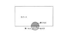
更に、上記した実施例の地図表示システムについては、デパートの出入口に適用することができる。この場合には、図5に示すようにデパートの出入口外に半円形状の第1セルがアンテナ11aによる送受信領域、出入口内に半円形状の第2セルがアンテナ12aによる送受信領域である。記憶装置14に記憶される地図データは、デパート出入口面から内部へ垂直に進む方向を地図の向きとしたデパート店内の売り場地図と、デパート出入口面からデパート外に垂直に進む方向を地図の向きとしたデパート外の地図とである。携帯端末装置2を所有するユーザがデパート外から図5に示す出入口に向けて移動して第1セルの範囲に入ると、上記した図3の動作により、携帯端末装置2の表示部33には、デパート店内の売り場地図が表示される。この地図表示においては、デパート出入口面から内部へ垂直に進む方向が表示部33の画面上方となる地図の向きとされる。同様に、携帯端末装置2を所有するユーザがデパート内から図5に示す出入口に向けて移動して第2セルの範囲に入ると、上記した図3の動作により、携帯端末装置2の表示部33には、デパート外の地図が表示される。この地図表示においては、デパート出入口面から外へ垂直に進む方向が表示部33の表示画面上方となる向きとされる。
【0022】
図6はデパートのエレベータの停止階に応じて動作する地図表示システムを示している。この地図表示システムは、ホスト装置41及び携帯端末装置42の他に、エレベータ(図示せず)の制御回路43を備えている。エレベータの制御回路43はエレベータの搭乗ボックス44を上下移動させて操作に応じた目標停止階に停止させるための制御を行う。
【0023】
ホスト装置41はブルートゥース送受信部が単一であることを除き、図1のホスト装置1と同様にブルートゥース送受信部51と、制御回路53と、記憶装置54とから構成される。ブルートゥース送受信部51のアンテナ51aは搭乗ボックス44内に設置されるが、その他は搭乗ボックス44外に設置されても良い。制御回路53はエレベータの制御回路43とは図示しないインターフェースを介して接続されている。エレベータの制御回路43は目標停止階のデータを制御回路53に供給する。記憶装置54にはデパートの各階の売り場地図を示す地図データが記憶されている。その売り場地図はエレベータの扉面に対して垂直な前方方向が表示される地図の向きとなっている。
【0024】
携帯端末装置42は図1の携帯端末装置2と同様の構成であり、電話送受信部61と、ブルートゥース送受信部62と、表示部63と、操作部64と、メモリ65と、制御回路66と、電話送話用のマイクロホン67と、受話用のスピーカ68を備えている。ホスト装置41と携帯端末装置42との間においてブルートゥース規格に対応した技術によって無線通信が行われることも図1のシステムと同様である。エレベータの搭乗ボックス44内はアンテナ51aによる送受信領域(セル)である。
【0025】
携帯端末装置42を所有するユーザがエレベータに搭乗すると、図7に示すように、携帯端末装置42のピコネットへの加入動作が行われる(ステップS11)。ピコネットにおいてホスト装置41はマスターとなり、携帯端末装置42はスレーブとなる。ホスト装置41ではブルートゥース送受信部51が作動し、ブルートゥース送受信部51と携帯端末装置42のブルートゥース送受信部62との間でピコネット加入のための通信が行われる。
【0026】
エレベータの扉が閉まると(ステップS12)、制御回路43は次に停止する目標停止階を示すデータをホスト装置41の制御回路53に供給する(ステップS13)。制御回路53は目標停止階を示すデータを受信すると、目標停止階に対応した地図データを記憶装置54から読み出す(ステップS14)。そして、その地図データをブルートゥース送受信部51によって携帯端末装置42に対して送信させる(ステップS15)。
【0027】
携帯端末装置42においては、ブルートゥース送受信部62が地図データを受信すると、その地図データはブルートゥース送受信部62から制御回路66に供給される。制御回路66は地図データを表示部63に供給して表示部63に表示させる(ステップS16)。携帯端末装置42の表示部63には、これからエレベータが停止する階の売り場地図が表示され、その売り場地図はエレベータの扉面に対して垂直な前方方向が表示部63の表示画面上方となる地図の向きとなっている。
【0028】
エレベータの搭乗ボックス44が目標停止階に移動して停止し(ステップS17)、扉が開き(ステップS18)、そして、ステップS12に戻って扉が閉まることになる。よって、ステップS13〜S16の動作が再度行われることにより表示部63には新たな目標停止階の売り場地図が表示される。
図8は地下鉄構内のT字通路において地図を表示する地図表示システムを示している。この地図表示システムにおいて、ホスト装置71はブルートゥース送受信部81〜83と、制御回路84と、記憶装置85とから構成される。ブルートゥース送受信部81は図9に示す通路P1に設置されたアンテナ81aによる円形の送受信領域(第1セル)内の携帯端末装置と通信可能である。ブルートゥース送受信部82,83は通路P1に対して垂直な通路P2に各々設置されたアンテナ82a,83aによる円形の送受信領域(第2及び第3セル)内の携帯端末装置と通信可能である。第1セル〜第3セルは通路P1と通路P2とのT字交差点近傍に位置し、第2セルは通路P1から見るとT字交差点の左側に位置し、第3セルは通路P1から見るとT字交差点の右側に位置する。
【0029】
記憶装置85には、第1セルからT字交差点方向を地図の向きとした地下鉄構内を示す第1地図データと、第2セルからT字交差点方向を地図の向きとした地下鉄構内を示す第2地図データと、第3セルからT字交差点方向を地図の向きとした地下鉄構内を示す第2地図データとが画像データとして記憶されている。
かかる図8の地図表示システムでは、ユーザが所有する携帯端末装置としては図1に示した携帯端末装置2が使用されるとする。
【0030】
次に、携帯端末装置2を有するユーザが通路P1又はP2を移動してT字交差点を通過する場合の携帯端末装置2の地図表示動作について説明する。
携帯端末装置2の制御回路36においては、図10に示すように、携帯端末装置2が第1セルに位置するか否かが判別される(ステップS31)。いずれかのセルの範囲に携帯端末装置2が存在する場合には、このステップS31の実行際に携帯端末装置2のピコネットへの加入動作によって、携帯端末装置2が存在するセルの情報はホスト装置71から得られる。
【0031】
第1セルに位置している場合には、ホスト装置71から第1セルに対応した第1地図データが受信され(ステップS32)、その地図データが示す地下鉄構内地図が表示部33に表示される(ステップS33)。その表示される地図では第1セルからT字交差点方向が表示部33の画面上方となる地図の向きとされる。
制御回路36は、ステップS33の実行後、携帯端末装置2が第2セルに位置するか否かが判別される(ステップS34)。すなわち、携帯端末装置2を所有するユーザが第1セルの範囲からT字交差点を左折して第2セルの範囲に到達したか否かが判別される。第2セルに位置している場合には、ステップS32で受信された第1地図データを回転変換する(ステップS35)。この第1地図データの回転変換では、その地図データが示す地下鉄構内地図を全体的に右に90度回転させることが行われる。そして、その変換された地図データが示す地下鉄構内地図が表示部33に表示される(ステップS36)。ステップS36の動作によって表示される地図ではT字交差点から第2セル方向が表示部33の表示画面上方となる地図の向きとされる。
【0032】
制御回路36は、ステップS34にて第2セルに位置していないと判別した場合には、携帯端末装置2が第3セルに位置するか否かが判別される(ステップS37)。すなわち、携帯端末装置2を所有するユーザが第1セルの範囲からT字交差点を右折して第3セルの範囲に到達したか否かが判別される。第3セルに位置している場合には、ステップS32で受信された第1地図データを回転変換する(ステップS38)。地図データの回転変換では、その第1地図データが示す地下鉄構内地図を全体的に左に90度回転させることが行われる。そして、その変換された地図データが示す地下鉄構内地図が表示部33に表示される(ステップS39)。ステップS39の動作によって表示される地図ではT字交差点から第3セル方向が表示部33の表示画面上方となる地図の向きとされる。
【0033】
制御回路36は、ステップS37にて第3セルに位置していないと判別した場合には、ステップS34に戻って携帯端末装置2が第2セルに位置するとか否かが判別される。
ステップS31において第1セルに位置していないと判別した場合には、図11に示すように、制御回路36は、携帯端末装置2が第2セルに位置するか否かが判別される(ステップS40)。第2セルに位置している場合には、ホスト装置71から第2セルに対応した第2地図データが受信され(ステップS41)、その地図データが示す地下鉄構内地図が表示部33に表示される(ステップS42)。その表示される地図では第2セルからT字交差点方向が表示部33の画面上方となる地図の向きとされる。
【0034】
制御回路36は、ステップS42の実行後、携帯端末装置2が第1セルに位置するか否かが判別される(ステップS43)。すなわち、携帯端末装置2を所有するユーザが第2セルの範囲からT字交差点を右折して第1セルの範囲に到達したか否かが判別される。第1セルに位置している場合には、ステップS41で受信された第2地図データを回転変換する(ステップS44)。この地図データの変換では、その第2地図データが示す地下鉄構内地図を全体的に左に90度回転させることが行われる。そして、その変換された地図データが示す地下鉄構内地図が表示部33に表示される(ステップS45)。ステップS45の動作によって表示される地図ではT字交差点から通路P1方向が表示部33の画面上方となる地図の向きとされる。
【0035】
制御回路36は、ステップS43にて第1セルに位置していないと判別した場合には、携帯端末装置2が第3セルに位置するか否かが判別される(ステップS46)。すなわち、携帯端末装置2を所有するユーザが第2セルの範囲からT字交差点を直進して第3セルの範囲に到達したか否かが判別される。第3セルに位置している場合には、そのまま現在の地図表示が継続される。
【0036】
制御回路36は、ステップS46にて第3セルに位置していないと判別した場合には、ステップS43に戻って携帯端末装置2が第1セルに位置するとか否かが判別される。
ステップS40において第2セルに位置していないと判別した場合には、制御回路36は、携帯端末装置2が第3セルに位置するか否かが判別される(ステップS47)。第3セルに位置している場合には、ホスト装置71から第3セルに対応した第3地図データが受信され(ステップS48)、その第3地図データが示す地下鉄構内地図が表示部33に表示される(ステップS49)。その表示される地図では第3セルからT字交差点方向が表示部33の画面上方となる地図の向きとされる。
【0037】
制御回路36は、ステップS49の実行後、携帯端末装置2が第1セルに位置するか否かが判別される(ステップS50)。すなわち、携帯端末装置2を所有するユーザが第3セルの範囲からT字交差点を左折して第1セルの範囲に到達したか否かが判別される。第1セルに位置している場合には、ステップS48で受信された第3地図データを回転変換する(ステップS51)。この地図データの変換では、その第3地図データが示す地下鉄構内地図を全体的に右に90度回転させることが行われる。そして、その変換された地図データが示す地下鉄構内地図が表示部33に表示される(ステップS52)。ステップS52の動作によって表示される地図ではT字交差点から通路P1方向が表示部33の画面上方となる地図の向きとされる。
【0038】
制御回路36は、ステップS50にて第1セルに位置していないと判別した場合には、携帯端末装置2が第2セルに位置するか否かが判別される(ステップS53)。すなわち、携帯端末装置2を所有するユーザが第3セルの範囲からT字交差点を直進して第2セルの範囲に到達したか否かが判別される。第2セルに位置している場合には、そのまま現在の地図表示が継続される。
【0039】
制御回路36は、ステップS53にて第2セルに位置していないと判別した場合には、ステップS50に戻って携帯端末装置2が第1セルに位置するとか否かが判別される。
ユーザが地下鉄構内のT字交差点を通過していずれの通路に移動した場合においても、かかる携帯端末装置2の動作によって表示部33にはユーザの進行方向が表示部33の画面上方となる地図の向きで地下鉄構内地図を常に表示させることができる。
【0040】
なお、かかる実施例においてはT字交差点を通過する場合について説明したが、L字通路や十字交差点を通過する場合にも本発明を適用することができる。また、交差点での右折及び左折の角度をホスト装置が携帯端末装置に通知するならば、必ずしも90度の回転ではなく、その通知角度に応じて地図データの回転変換を行うことができる。
【0041】
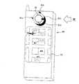
図12は地磁気センサ39を有する携帯端末装置40の構成を示している。この携帯端末装置40は、地磁気センサ39を備える他は、図1に示した携帯端末装置2の構成と同様に、電話送受信部31と、ブルートゥース送受信部32と、表示部33と、操作部34と、メモリ35と、CPUからなる制御回路36と、マイクロホン37と、スピーカ38とを備えている。地磁気センサ39は図13に示すように、携帯端末装置40の前面の表示部33の下方に配置され、北方向を基準方向として携帯端末装置40の上方の向き、すなわち方位を検出する。
【0042】
携帯端末装置40を所有するユーザが地下鉄構内から図2に示す階段を移動して第1セルの範囲に入ると、図3に示したように、携帯端末装置40のピコネットへの加入動作が行われる(ステップS1)。ホスト装置1ではブルートゥース送受信部11が作動し、ブルートゥース送受信部11と携帯端末装置40のブルートゥース送受信部32との間でピコネット加入のための通信が行われる。ピコネットへの加入動作の終了後、ホスト装置1の制御回路13は第1セルに対応した地上の地図を示す地図データを記憶装置14から読み出し(ステップS2)、その地図データをブルートゥース送受信部11によって携帯端末装置40に対して送信させる(ステップS3)。
【0043】
携帯端末装置40においては、図14に示すように、ブルートゥース送受信部32が地図データを受信すると(ステップS61)、その地図データはブルートゥース送受信部32から制御回路36に供給される。制御回路36は地図データを表示部33に供給して表示部33に表示させる(ステップS62)。携帯端末装置40の表示部33には、図11に示すように地図が表示される。この地図表示においては、地下鉄構内からその出入口へ進む階段の上り方向が表示部33の画面上方となる地図の向きとされる。
【0044】
制御回路36は地磁気センサ39から方位データを獲得し(ステップS63)、その方位データが示す方位角に応じて地図データを回転変換する(ステップS64)。この地図データの回転変換では、その地図データが示す地図を全体的に方位データが示す方位角だけ回転させることが行われる。制御回路36は回転変換後の地図データを表示部33に供給して表示部33に表示させる(ステップS65)。この地図表示においては、地下鉄構内からその出入口へ進む階段の上り方向と表示部33の地図の向きとが同一となる。
【0045】
ステップS65の実行後、ステップS63〜S65が繰り返し実行される。よって、地下鉄構内からその出入口へ進む階段の上り方向と表示部33の表示地図の向きとが携帯端末装置40の向きに拘わらず常に同一となる。
また、携帯端末装置2を所有するユーザが地下鉄構内に入るために図2に示す階段入口に移動して第2セルの範囲に入った場合には、地下鉄構内の地図が表示され、地下鉄の出入口から階段の下り方向と表示部33の表示地図の向きとが携帯端末装置40の向きに拘わらず常に同一となる。
【0046】
上記した実施例においては、方位検出手段として地磁気センサ39が携帯端末装置40に備えられているが、これに限らず、他の方位検出手段を用いても良い。例えば、図15に示すように携帯端末装置90にCCDカメラ91と、そのCCDカメラ91のレンズ周囲の四方に棒92a〜92dとを設けても良い。この例の場合には、携帯端末装置90を水平に保ち、太陽光、月光、或いは所定の星光(例えば、北極星)によって棒92a〜92dによってできる影をCCDカメラ91によって検出し、太陽光、月光、或いは所定の星光による予め定められた影と日時情報との関係に応じて携帯端末装置90の方位を算出することができる。
【0047】
なお、上記した各実施例においては、ホスト装置と携帯端末装置の間の通信にはブルートゥース規格に準拠した無線通信技術が用いられているが、IrDA(Infrared Data Association)、HomeRF(Home Radio Frequency)、IEEE 802.11等の他の無線通信技術を用いても良い。
【0048】
【発明の効果】
以上の如く、本発明によれば、移動端末装置の進行方向が表示画面の表示上向きとなるように表示されるので、移動先の方角と表示地図の向きとの関係が容易に分かる。
【図面の簡単な説明】
【図1】本発明による地図表示システムの構成を示すブロック図である。
【図2】図1のシステムの地図表示動作を説明するための地下鉄出入口付近の地図である。
【図3】図1のシステムの地図表示動作を示すシーケンス図である。
【図4】図1のシステム中の携帯端末装置における地図の表示例を示す図である。
【図5】図1のシステムをデパートの出入口に適用する場合のセルを示す図である。
【図6】本発明による地図表示システムの構成を示すブロック図である。
【図7】図6のシステムの地図表示動作を示すシーケンス図である。
【図8】本発明による地図表示システムの構成を示すブロック図である。
【図9】図8のシステムの地図表示動作を説明するためのT字通路の地図である。
【図10】図8のシステム中の携帯端末装置の地図表示動作を示すフローチャートである。
【図11】図10の地図表示動作の続き部分を示すフローチャートである。
【図12】地図表示システムに適用される携帯端末装置の構成を示すブロック図である。
【図13】図12の携帯端末装置の外観を示す図である。
【図14】図12の携帯端末装置の動作を示すフローチャートである。
【図15】他の携帯端末装置の外観を示す図である。
【符号の説明】
1,41,71 ホスト装置
2,40,42 携帯端末装置
11,12,32,51,62,81〜83 ブルートゥース送受信部
13,36,43,53,66,84 制御回路
39 地磁気センサ[0001]
[Technical field to which the invention belongs]
The present invention relates to a map display system using a mobile terminal device.
[0002]
[Prior art]
Displaying a map on a display screen of a mobile phone has already been performed as one of information providing services provided by a mobile phone company or its partner. Usually, a data server that provides map data for each region is provided, and a region desired by the user of the mobile phone is designated by operation, information on the designated region is transmitted to the data server, and the corresponding map data is stored in the data server. Is sent wirelessly to the mobile phone, and a map of the desired area is displayed on the display screen of the mobile phone.
[0003]
[Problems to be solved by the invention]
A user who owns a mobile terminal device such as a cellular phone usually looks at a map at an unfamiliar destination, and in such cases, the direction is often not well understood. However, since the map displayed on the display screen of the mobile terminal device is normally displayed with north facing upward, there is a problem that it is difficult for the user to understand the displayed map unless the north direction is immediately known at the destination. .
[0004]
Accordingly, an object of the present invention is to provide a map display system capable of displaying a map on a mobile terminal device so that the relationship between the direction of the destination and the orientation of the display map can be easily understood.
[0005]
[Means for Solving the Problems]
The map display system of the present invention is a map display system for displaying a map on a display unit of the mobile terminal device by performing communication between the mobile terminal device and the host device, wherein the host device is the mobile terminal device. First terminal detecting means for detecting that the mobile terminal device is present in the first area on the passage, and when the presence of the mobile terminal device in the first area is detected by the first terminal detecting means, First transmitting means for transmitting first map data indicating a map in the vicinity of the area to the mobile terminal device;Detecting means for detecting that the mobile terminal device is present in a second region on the passage in a passage direction different from the first region; and presence of the mobile terminal device in the second region. Second transmission means for transmitting second map data indicating a map near the second region to the mobile terminal device when detected; The mobile terminal device includes a receiving unit that receives the first map data transmitted by the first transmitting unit, an azimuth detecting unit that detects an azimuth of the mobile terminal device, and the mobile terminal device in the passage. The map data received by the receiving means is converted according to the direction detected by the direction detecting means so that the traveling direction of the display is upward, and the map indicated by the converted map data is displayed on the display unit. And control meansWhen the second transmission means detects the presence of the mobile terminal device in the second region immediately after detecting the presence of the mobile terminal device in the first region, a map near the second region is detected. The second map data indicating is not transmitted to the mobile terminal device It is characterized by that.
[0007]
The map display method of the present invention is a map display method for displaying a map on the display unit of the mobile terminal device by performing communication between the mobile terminal device and the host device,In the mobile terminal device, the direction of the mobile terminal device is detected, the received map data is converted according to the detected direction so that the traveling direction of the mobile terminal device in the passage is upward, and the converted map A map indicated by data is displayed on the display unit, and when the host device detects that the mobile terminal device is present in a first area on the passage, a first map showing a map near the first area When the data is transmitted to the mobile terminal device and the mobile terminal device detects that the mobile terminal device exists in a second region having a position different from the first region in the passage direction on the passage, the vicinity of the second region The second map data indicating the map of the mobile terminal device is transmitted to the mobile terminal device, and immediately after detecting the presence of the mobile terminal device in the first region, the second of the mobile terminal device Not perform transmission to the mobile terminal device of the second map data when it detects the presence of frequency It is characterized by that.
[0011]
The mobile terminal device of the present invention includes a display for displaying a map, receiving means for receiving map data, azimuth detecting means for detecting the azimuth of the mobile terminal device, and azimuth detected by the azimuth detecting means. And a control unit that converts the map data received by the receiving unit so that the display map on the display unit has a predetermined display orientation, and displays the map indicated by the converted map data on the display unit, A mobile terminal device comprising:When the map data corresponding to a cell different from the one cell is received after the receiving means receives map data corresponding to one cell, the control means corresponds to the map corresponding to the different cell. Ignore the data and continue displaying the map It is characterized by that.
[0012]
A mobile terminal device according to the present invention is a mobile terminal device comprising: receiving means for receiving map data; and control means for displaying a map indicated by the map data received by the receiving means on a display unit. If map data corresponding to a cell different from one cell is received after the receiving means receives map data corresponding to one cell, the map data corresponding to the different cell is ignored. It is characterized by continuing the map display until then.
[0013]
DETAILED DESCRIPTION OF THE INVENTION
Hereinafter, embodiments of the present invention will be described in detail with reference to the drawings.
FIG. 1 shows a map display system according to the present invention. This map display system includes a
[0014]
As shown in FIG. 1, the
[0015]
The
[0016]
When the user who owns the
[0017]
After completing the operation of joining the piconet, the
In the mobile
[0018]
The map display may be performed in response to the operation of the
When the user who owns the mobile
[0019]
After completing the operation of joining the piconet, the
In the mobile
[0020]
When the mobile
[0021]
In the above-described embodiment, the map data is transmitted only to the mobile
Furthermore, the map display system of the above-described embodiment can be applied to the entrance / exit of a department store. In this case, as shown in FIG. 5, the semicircular first cell outside the entrance / exit of the department store is a transmission / reception region by the
[0022]
FIG. 6 shows a map display system that operates in accordance with a stop floor of an elevator of a department store. This map display system includes an elevator (not shown)
[0023]
The host device 41 includes a Bluetooth transmission /
[0024]
The mobile terminal device 42 has the same configuration as the mobile
[0025]
When the user who owns the mobile terminal device 42 gets on the elevator, the mobile terminal device 42 joins the piconet as shown in FIG. 7 (step S11). In the piconet, the host device 41 is a master, and the mobile terminal device 42 is a slave. In the host device 41, the Bluetooth transmission /
[0026]
When the elevator door is closed (step S12), the
[0027]
In the mobile terminal device 42, when the Bluetooth transmission /
[0028]
The
FIG. 8 shows a map display system for displaying a map in a T-shaped passage in a subway premises. In this map display system, the host device 71 includes Bluetooth transmission /
[0029]
The
In the map display system of FIG. 8, it is assumed that the mobile
[0030]
Next, the map display operation of the mobile
In the
[0031]
If it is located in the first cell, the first map data corresponding to the first cell is received from the host device 71 (step S32), and the subway campus map indicated by the map data is displayed on the
After executing step S33, the
[0032]
If the
[0033]
When it is determined in step S37 that the
If it is determined in step S31 that the mobile
[0034]
After executing step S42, the
[0035]
If the
[0036]
If the
If it is determined in step S40 that the mobile
[0037]
After executing step S49, the
[0038]
When it is determined in step S50 that the
[0039]
If the
Even when the user moves to any passage through the T-shaped intersection in the subway premises, the mobile
[0040]
In this embodiment, the case of passing through a T-shaped intersection has been described. However, the present invention can also be applied to a case of passing through an L-shaped passage or a cross intersection. Further, if the host device notifies the mobile terminal device of the angle of the right turn and the left turn at the intersection, the rotation of the map data can be performed according to the notification angle, not necessarily the rotation of 90 degrees.
[0041]
FIG. 12 shows the configuration of a mobile
[0042]
When the user who owns the mobile
[0043]
In the mobile
[0044]
The
[0045]
After step S65 is executed, steps S63 to S65 are repeatedly executed. Therefore, the upward direction of the stairs going from the subway yard to the entrance and the direction of the display map of the
When the user who owns the mobile
[0046]
In the above-described embodiment, the
[0047]
In each of the above-described embodiments, wireless communication technology compliant with the Bluetooth standard is used for communication between the host device and the mobile terminal device, but IrDA (Infrared Data Association), HomeRF (Home Radio Frequency) Other wireless communication technologies such as IEEE 802.11 may be used.
[0048]
【The invention's effect】
As described above, according to the present invention, since the traveling direction of the mobile terminal device is displayed so as to face upward on the display screen, the relationship between the direction of the destination and the orientation of the display map can be easily understood.
[Brief description of the drawings]
FIG. 1 is a block diagram showing a configuration of a map display system according to the present invention.
FIG. 2 is a map in the vicinity of a subway entrance / exit for explaining the map display operation of the system of FIG.
FIG. 3 is a sequence diagram showing a map display operation of the system of FIG. 1;
4 is a diagram showing a display example of a map in the mobile terminal device in the system of FIG. 1;
FIG. 5 is a diagram showing a cell when the system of FIG. 1 is applied to an entrance / exit of a department store.
FIG. 6 is a block diagram showing a configuration of a map display system according to the present invention.
7 is a sequence diagram showing a map display operation of the system of FIG.
FIG. 8 is a block diagram showing a configuration of a map display system according to the present invention.
9 is a map of a T-shaped passage for explaining a map display operation of the system of FIG.
10 is a flowchart showing a map display operation of the mobile terminal device in the system of FIG.
11 is a flowchart showing a continuation of the map display operation of FIG.
FIG. 12 is a block diagram showing a configuration of a mobile terminal device applied to the map display system.
13 is a diagram showing an external appearance of the mobile terminal device of FIG.
14 is a flowchart showing the operation of the mobile terminal device of FIG.
FIG. 15 is a diagram illustrating an appearance of another mobile terminal device.
[Explanation of symbols]
1, 41, 71 Host device
2, 40, 42 Mobile terminal device
11, 12, 32, 51, 62, 81-83 Bluetooth transceiver
13, 36, 43, 53, 66, 84 Control circuit
39 Geomagnetic sensor
Claims (9)
Translated fromJapanese前記ホスト装置は、前記移動端末装置が通路上の第1の領域に存在することを検出する第1端末検出手段と、前記第1端末検出手段によって前記移動端末装置の前記第1の領域における存在が検出されたときに前記第1の領域付近の地図を示す第1地図データを前記移動端末装置に送信する第1送信手段と、前記移動端末装置が前記通路上において前記第1の領域とは通路方向における位置が異なる第2の領域に存在することを検出する検出手段と、前記移動端末装置の前記第2の領域における存在を検出したときに前記第2の領域付近の地図を示す第2地図データを前記移動端末装置に送信する第2送信手段と、を備え、
前記移動端末装置は、前記第1送信手段によって送信された第1地図データを受信する受信手段と、前記移動端末装置の方位を検出する方位検出手段と、前記通路における前記移動端末装置の進行方向が表示上向きとなるように前記方位検出手段によって検出された方位に応じて前記受信手段によって受信された地図データを変換し、変換後の地図データが示す地図を前記表示部に表示させる制御手段と、を備え、
前記第2送信手段は、前記移動端末装置の前記第1の領域における存在を検出した直後に、前記移動端末装置の前記第2の領域における存在を検出したときには前記第2の領域付近の地図を示す第2地図データの前記移動端末装置への送信を実行しないことを特徴とする地図表示システム。A map display system for communicating between a mobile terminal device and a host device and displaying a map on a display unit of the mobile terminal device,
The host device detects the presence of the mobile terminal device in a first area on the passage, and the presence of the mobile terminal device in the first area by the first terminal detection means. First transmission means for transmitting first map data indicating a map in the vicinity of the first area to the mobile terminal apparatus when the mobile terminal apparatus is detected, and themobile terminal apparatus is the first area on the passage. Detection means for detecting that the position in the direction of the passage is in a second area different from each other; and second indicating a map in the vicinity of the second area when the presence of the mobile terminal device in the second area is detected. Second transmission means for transmitting map data to the mobile terminal device ,
The mobile terminal device includes a receiving unit that receives the first map data transmitted by the first transmitting unit, an azimuth detecting unit that detects an azimuth of the mobile terminal device, and a traveling direction of the mobile terminal device in the passage Control means for converting the map data received by the receiving means in accordance with the direction detected by the direction detecting means so that the display is facing upward, and displaying the map indicated by the converted map data on the display unit; With
The second transmitting means detects a presence of the mobile terminal apparatus in the second area immediately after detecting the presence of the mobile terminal apparatus in the second area, and detects a map near the second area. Transmission of the 2nd map data shown to the said mobile terminal apparatus is not performed, The map display system characterizedby the above-mentioned .
前記移動端末装置では、前記移動端末装置の方位を検出し、通路における前記移動端末装置の進行方向が表示上向きとなるように検出した方位に応じて受信した地図データを変換し、変換後の地図データが示す地図を前記表示部に表示させ、
前記ホスト装置は、前記移動端末装置が通路上の第1の領域に存在することを検出したときには前記第1の領域付近の地図を示す第1地図データを前記移動端末装置に送信し、前記移動端末装置が前記通路上において前記第1の領域とは通路方向における位置が異なる第2の領域に存在することを検出したときには前記第2の領域付近の地図を示す第2地図データを前記移動端末装置に送信する一方、前記移動端末装置の前記第1の領域における存在を検出した直後に、前記移動端末装置の前記第2の領域における存在を検出したときには前記第2地図データの前記移動端末装置への送信を実行しないことを特徴とする地図表示方法。A map display method for communicating between a mobile terminal device and a host device to display a map on a display unit of the mobile terminal device,
In the mobile terminal device, the direction of the mobile terminal device is detected, the received map data is converted according to the detected direction so that the traveling direction of the mobile terminal device in the passage is upward, and the converted map The map indicated by the data is displayed on the display unit,
When the host device detects that the mobile terminal device exists in the first area on the passage, the host device transmits first map data indicating a map near the first area to the mobile terminal device, and the movement When the terminal device detects that the terminal device is present in a second region having a position different from the first region in the passage direction on the passage, second map data indicating a map in the vicinity of the second region is stored in the mobile terminal. When the presence of the mobile terminal device in the second region is detected immediately after detecting the presence of the mobile terminal device in the first region, the mobile terminal device of the second map data is transmitted to the deviceMAP dISPLAYwayto characterized in thatit does not perform the transmission to.
前記制御手段は、前記受信手段によって1のセルに対応する地図データが受信された後に、前記1のセルとは異なるセルに対応する地図データが受信された場合にはその異なるセルに対応する地図データを無視してそれまでの地図表示を継続させることを特徴とする移動端末装置。Display for displaying a map, receiving means for receiving map data, azimuth detecting means for detecting the azimuth of the mobile terminal device, and display on the display unit according to the azimuth detected by the azimuth detecting means Control means for converting the map data received by the receiving means so that the map has a predetermined display orientation and displaying the map indicated by the converted map data on the display unit. And
When the map data corresponding to a cell different from the one cell is received after the receiving means receives map data corresponding to one cell, the control means corresponds to the map corresponding to the different cell. Amobile terminal device characterizedby ignoring data and continuing the map display so far .
Priority Applications (4)
| Application Number | Priority Date | Filing Date | Title |
|---|---|---|---|
| JP2000352508AJP4409749B2 (en) | 2000-11-20 | 2000-11-20 | Map display system |
| US09/987,995US6904358B2 (en) | 2000-11-20 | 2001-11-16 | System for displaying a map |
| DE60117093TDE60117093T2 (en) | 2000-11-20 | 2001-11-20 | System for map display |
| EP01127664AEP1207508B1 (en) | 2000-11-20 | 2001-11-20 | System for displaying a map |
Applications Claiming Priority (1)
| Application Number | Priority Date | Filing Date | Title |
|---|---|---|---|
| JP2000352508AJP4409749B2 (en) | 2000-11-20 | 2000-11-20 | Map display system |
Publications (2)
| Publication Number | Publication Date |
|---|---|
| JP2002156243A JP2002156243A (en) | 2002-05-31 |
| JP4409749B2true JP4409749B2 (en) | 2010-02-03 |
Family
ID=18825392
Family Applications (1)
| Application Number | Title | Priority Date | Filing Date |
|---|---|---|---|
| JP2000352508AExpired - Fee RelatedJP4409749B2 (en) | 2000-11-20 | 2000-11-20 | Map display system |
Country Status (4)
| Country | Link |
|---|---|
| US (1) | US6904358B2 (en) |
| EP (1) | EP1207508B1 (en) |
| JP (1) | JP4409749B2 (en) |
| DE (1) | DE60117093T2 (en) |
Families Citing this family (31)
| Publication number | Priority date | Publication date | Assignee | Title |
|---|---|---|---|---|
| JP3921351B2 (en)* | 2001-03-12 | 2007-05-30 | 株式会社ケンウッド | Pedestrian guidance system |
| JP3721141B2 (en)* | 2002-03-25 | 2005-11-30 | 松下電器産業株式会社 | Mobile terminal device |
| US7054627B1 (en)* | 2002-04-29 | 2006-05-30 | Advanced Micro Devices, Inc. | Method and system for locating a wireless network access point at a mobile computing device |
| JP2003348637A (en)* | 2002-05-23 | 2003-12-05 | Nec Corp | Mobile communication system |
| FI118247B (en)* | 2003-02-26 | 2007-08-31 | Fraunhofer Ges Forschung | Method for creating a natural or modified space impression in multi-channel listening |
| JP2005070220A (en)* | 2003-08-21 | 2005-03-17 | Navitime Japan Co Ltd | Map-providing device, mobile terminal, map providing method, map display method, map-providing program, and map display program |
| KR100555107B1 (en)* | 2003-10-01 | 2006-02-24 | 팅크웨어(주) | Path providing method and system using mobile communication terminal providing scroll function |
| EP1767900A4 (en)* | 2004-07-15 | 2010-01-20 | Amosense Co Ltd | Mobile terminal device |
| US7236882B2 (en)* | 2005-01-26 | 2007-06-26 | Broadcom Corporation | Downloading map segment(s) to a cell phone based upon its GPS coordinates and mobility |
| US9402272B2 (en)* | 2005-03-17 | 2016-07-26 | Core Wireless Licensing S.A.R.L. | Electronic device having a cellular communication mode and a radio communication mode |
| KR100681132B1 (en)* | 2005-05-19 | 2007-02-08 | 에스케이 텔레콤주식회사 | Way guidance method and device using location based service and system including the device |
| EP1788357A1 (en)* | 2005-11-16 | 2007-05-23 | Alcatel Lucent | System for locating pedestrian user |
| KR100651594B1 (en)* | 2005-12-29 | 2006-11-30 | 주식회사 팬택 | Mobile communication terminal providing the direction indication function and the direction indication method |
| ES1063213Y (en)* | 2006-02-03 | 2007-01-16 | Oliver Juan Poyatos | VIA SATELLITE PORTABLE ELECTRONIC DEVICE |
| JP2007240273A (en)* | 2006-03-07 | 2007-09-20 | Nippon Signal Co Ltd:The | Guide system |
| JP2007147632A (en)* | 2006-12-19 | 2007-06-14 | Nec Corp | Method of providing route, method of guiding route, charging method, server for providing route, user terminal, charging server, and program |
| US8825387B2 (en) | 2008-07-25 | 2014-09-02 | Navteq B.V. | Positioning open area maps |
| US20100021013A1 (en)* | 2008-07-25 | 2010-01-28 | Gale William N | Open area maps with guidance |
| JP5363256B2 (en)* | 2009-09-28 | 2013-12-11 | Kddi株式会社 | Information terminal equipment |
| PL2407935T3 (en)* | 2009-11-23 | 2013-05-31 | Kapsch Trafficcom Ag | Control device for a road toll system |
| JP4736070B2 (en)* | 2009-11-25 | 2011-07-27 | アイチ・マイクロ・インテリジェント株式会社 | Portable navigation system |
| US20120208605A1 (en)* | 2011-02-11 | 2012-08-16 | Qualcomm Incorporated | Mobile device power optimization with peripheral sensors with standard interfaces |
| US8706137B2 (en) | 2011-08-02 | 2014-04-22 | Qualcomm Incorporated | Likelihood of mobile device portal transition |
| WO2013104127A1 (en) | 2012-01-12 | 2013-07-18 | Google Inc. | Generating an indoor map model |
| WO2013104128A1 (en)* | 2012-01-12 | 2013-07-18 | Google Inc. | Navigating using indoor map representation |
| CN103454659B (en)* | 2012-06-04 | 2016-09-28 | 中兴通讯股份有限公司 | In a kind of navigation, auxiliary adjusts the method and device of moving direction |
| JP6172987B2 (en)* | 2013-03-22 | 2017-08-02 | 株式会社パスコ | Azimuth angle estimation apparatus and azimuth angle estimation program |
| JP2015206735A (en)* | 2014-04-22 | 2015-11-19 | 清水建設株式会社 | POSITIONING INFORMATION PROVIDING DEVICE AND ITS CONTROL METHOD |
| US20160210669A1 (en)* | 2015-01-17 | 2016-07-21 | Alfred Xueliang Xin | On-site sales and commercial search method and system |
| US20160171543A1 (en)* | 2014-12-10 | 2016-06-16 | Alfred Xueliang Xin | On-site sales and new products advertisements search method and system |
| WO2018211655A1 (en)* | 2017-05-18 | 2018-11-22 | 三菱電機株式会社 | Position detection device, elevator control device, and elevator system |
Family Cites Families (16)
| Publication number | Priority date | Publication date | Assignee | Title |
|---|---|---|---|---|
| JPH08168074A (en)* | 1994-12-15 | 1996-06-25 | Nec Corp | Position management system for moving body communication |
| US5699056A (en)* | 1994-12-28 | 1997-12-16 | Omron Corporation | Traffic information system |
| GB2298539A (en) | 1995-02-27 | 1996-09-04 | Richard Deehan | Portable guidance device |
| US6127945A (en)* | 1995-10-18 | 2000-10-03 | Trimble Navigation Limited | Mobile personal navigator |
| JP3743037B2 (en)* | 1995-11-01 | 2006-02-08 | 株式会社日立製作所 | Information providing method to mobile terminal, information providing system, and mobile terminal |
| BR9700161A (en) | 1996-02-01 | 2004-08-17 | Personal Marketing S A | Process and device for selectively establishing a link, transmitter unit and receiver unit |
| US5924040A (en)* | 1996-11-20 | 1999-07-13 | Telxon Corporation | Wireless communication system having base station with adjustable power transceiver for locating mobile devices |
| JPH10304453A (en)* | 1997-04-25 | 1998-11-13 | Nec Corp | Mobile communication system |
| US6119002A (en)* | 1997-10-06 | 2000-09-12 | Nokia Mobile Phones Limited | Mobile station having methods and apparatus for performing neighbor channel measurements from analog control channel |
| FR2782225B1 (en) | 1998-08-05 | 2000-12-01 | Arnaud Nicolas Christian Roy | SYSTEM FOR WIRELESS BROADCASTING, DIGITAL INFORMATION FROM A DISPLAY PANEL TO A PORTABLE RECEIVER |
| US6754266B2 (en)* | 1998-10-09 | 2004-06-22 | Microsoft Corporation | Method and apparatus for use in transmitting video information over a communication network |
| EP1059737A4 (en) | 1998-12-24 | 2006-04-05 | Sumitomo Electric Industries | ROAD / VEHICLE COMMUNICATION SYSTEM |
| US6184829B1 (en)* | 1999-01-08 | 2001-02-06 | Trueposition, Inc. | Calibration for wireless location system |
| US6396457B1 (en)* | 2000-02-29 | 2002-05-28 | Texas Instruments Incorporated | Concentrator for coupling local wireless networks to a wired network |
| US6246376B1 (en)* | 2000-06-28 | 2001-06-12 | Texas Instruments Incorporated | Wireless location and direction indicator for multiple devices |
| US6327533B1 (en)* | 2000-06-30 | 2001-12-04 | Geospatial Technologies, Inc. | Method and apparatus for continuously locating an object |
- 2000
- 2000-11-20JPJP2000352508Apatent/JP4409749B2/ennot_activeExpired - Fee Related
- 2001
- 2001-11-16USUS09/987,995patent/US6904358B2/ennot_activeExpired - Lifetime
- 2001-11-20EPEP01127664Apatent/EP1207508B1/ennot_activeExpired - Lifetime
- 2001-11-20DEDE60117093Tpatent/DE60117093T2/ennot_activeExpired - Lifetime
Also Published As
| Publication number | Publication date |
|---|---|
| EP1207508A3 (en) | 2003-07-02 |
| US6904358B2 (en) | 2005-06-07 |
| DE60117093D1 (en) | 2006-04-20 |
| EP1207508A2 (en) | 2002-05-22 |
| US20020061755A1 (en) | 2002-05-23 |
| DE60117093T2 (en) | 2006-09-28 |
| EP1207508B1 (en) | 2006-02-08 |
| JP2002156243A (en) | 2002-05-31 |
Similar Documents
| Publication | Publication Date | Title |
|---|---|---|
| JP4409749B2 (en) | Map display system | |
| JP5930478B2 (en) | Area recognition apparatus and method for portable terminal | |
| KR101910936B1 (en) | System and method for developing a wi-fi access point map using sensors in a wireless mobile device | |
| CN101171798B (en) | Apparatus and method for displaying availability of wireless lan | |
| CN102960036B (en) | Crowdsourced Vision and Sensor Mapping | |
| US7373218B2 (en) | Image distribution system | |
| EP1304547A2 (en) | Communication navigation | |
| JP2014192813A (en) | Terminal, method and program for detecting specific position on basis of received radio wave strength per channel | |
| EP3092830B1 (en) | Feedback in a positioning system | |
| CN113556680B (en) | Fingerprint data processing method, medium and mobile robot | |
| US20210247191A1 (en) | Indoor direction guiding method and system therefor | |
| JP2004245657A (en) | Mobile terminal device and information providing system | |
| JP2011113245A (en) | Position recognition device | |
| JP2019128258A (en) | Navigation method, program, and information processing device | |
| WO2020226103A1 (en) | Position information providing device, method, and program | |
| JP2006349595A (en) | Route guide system | |
| JP2019184598A (en) | Route guidance system, portable terminal, and method for route guidance | |
| KR20080094369A (en) | Mobile communication terminal and its control method | |
| JP3531667B2 (en) | Information provision system | |
| JP2003061123A (en) | Mobile station and service providing device | |
| US11983831B1 (en) | Systems and methods for collaborative location tracking and sharing using augmented reality | |
| JP2023151902A (en) | Region identification system | |
| JP2023151901A (en) | Region identification system | |
| JP2007333651A (en) | Route guidance system, navigation system | |
| JP2002324289A (en) | Security terminal |
Legal Events
| Date | Code | Title | Description |
|---|---|---|---|
| A621 | Written request for application examination | Free format text:JAPANESE INTERMEDIATE CODE: A621 Effective date:20051226 | |
| A977 | Report on retrieval | Free format text:JAPANESE INTERMEDIATE CODE: A971007 Effective date:20070704 | |
| A131 | Notification of reasons for refusal | Free format text:JAPANESE INTERMEDIATE CODE: A131 Effective date:20080129 | |
| A521 | Written amendment | Free format text:JAPANESE INTERMEDIATE CODE: A523 Effective date:20080331 | |
| A131 | Notification of reasons for refusal | Free format text:JAPANESE INTERMEDIATE CODE: A131 Effective date:20080520 | |
| A521 | Written amendment | Free format text:JAPANESE INTERMEDIATE CODE: A523 Effective date:20080715 | |
| A131 | Notification of reasons for refusal | Free format text:JAPANESE INTERMEDIATE CODE: A131 Effective date:20090203 | |
| A521 | Written amendment | Free format text:JAPANESE INTERMEDIATE CODE: A523 Effective date:20090403 | |
| TRDD | Decision of grant or rejection written | ||
| A01 | Written decision to grant a patent or to grant a registration (utility model) | Free format text:JAPANESE INTERMEDIATE CODE: A01 Effective date:20091110 | |
| A01 | Written decision to grant a patent or to grant a registration (utility model) | Free format text:JAPANESE INTERMEDIATE CODE: A01 | |
| A61 | First payment of annual fees (during grant procedure) | Free format text:JAPANESE INTERMEDIATE CODE: A61 Effective date:20091112 | |
| R150 | Certificate of patent or registration of utility model | Free format text:JAPANESE INTERMEDIATE CODE: R150 | |
| FPAY | Renewal fee payment (event date is renewal date of database) | Free format text:PAYMENT UNTIL: 20121120 Year of fee payment:3 | |
| FPAY | Renewal fee payment (event date is renewal date of database) | Free format text:PAYMENT UNTIL: 20131120 Year of fee payment:4 | |
| LAPS | Cancellation because of no payment of annual fees |