JP4407772B2 - projector - Google Patents
projectorDownload PDFInfo
- Publication number
- JP4407772B2 JP4407772B2JP2009030879AJP2009030879AJP4407772B2JP 4407772 B2JP4407772 B2JP 4407772B2JP 2009030879 AJP2009030879 AJP 2009030879AJP 2009030879 AJP2009030879 AJP 2009030879AJP 4407772 B2JP4407772 B2JP 4407772B2
- Authority
- JP
- Japan
- Prior art keywords
- connection
- server
- projector
- image data
- client
- Prior art date
- Legal status (The legal status is an assumption and is not a legal conclusion. Google has not performed a legal analysis and makes no representation as to the accuracy of the status listed.)
- Expired - Lifetime
Links
Images


Classifications
- H—ELECTRICITY
- H04—ELECTRIC COMMUNICATION TECHNIQUE
- H04N—PICTORIAL COMMUNICATION, e.g. TELEVISION
- H04N1/00—Scanning, transmission or reproduction of documents or the like, e.g. facsimile transmission; Details thereof
- H04N1/00127—Connection or combination of a still picture apparatus with another apparatus, e.g. for storage, processing or transmission of still picture signals or of information associated with a still picture
- H04N1/00204—Connection or combination of a still picture apparatus with another apparatus, e.g. for storage, processing or transmission of still picture signals or of information associated with a still picture with a digital computer or a digital computer system, e.g. an internet server
- H04N1/00209—Transmitting or receiving image data, e.g. facsimile data, via a computer, e.g. using e-mail, a computer network, the internet, I-fax
- H04N1/00222—Transmitting or receiving image data, e.g. facsimile data, via a computer, e.g. using e-mail, a computer network, the internet, I-fax details of image data generation or reproduction, e.g. scan-to-email or network printing
- G—PHYSICS
- G06—COMPUTING OR CALCULATING; COUNTING
- G06F—ELECTRIC DIGITAL DATA PROCESSING
- G06F21/00—Security arrangements for protecting computers, components thereof, programs or data against unauthorised activity
- G06F21/30—Authentication, i.e. establishing the identity or authorisation of security principals
- G06F21/31—User authentication
- G—PHYSICS
- G06—COMPUTING OR CALCULATING; COUNTING
- G06F—ELECTRIC DIGITAL DATA PROCESSING
- G06F13/00—Interconnection of, or transfer of information or other signals between, memories, input/output devices or central processing units
- G—PHYSICS
- G06—COMPUTING OR CALCULATING; COUNTING
- G06F—ELECTRIC DIGITAL DATA PROCESSING
- G06F15/00—Digital computers in general; Data processing equipment in general
- G06F15/16—Combinations of two or more digital computers each having at least an arithmetic unit, a program unit and a register, e.g. for a simultaneous processing of several programs
- H—ELECTRICITY
- H04—ELECTRIC COMMUNICATION TECHNIQUE
- H04L—TRANSMISSION OF DIGITAL INFORMATION, e.g. TELEGRAPHIC COMMUNICATION
- H04L61/00—Network arrangements, protocols or services for addressing or naming
- H04L61/50—Address allocation
- H04L61/5007—Internet protocol [IP] addresses
- H04L61/5014—Internet protocol [IP] addresses using dynamic host configuration protocol [DHCP] or bootstrap protocol [BOOTP]
- H—ELECTRICITY
- H04—ELECTRIC COMMUNICATION TECHNIQUE
- H04N—PICTORIAL COMMUNICATION, e.g. TELEVISION
- H04N1/00—Scanning, transmission or reproduction of documents or the like, e.g. facsimile transmission; Details thereof
- H04N1/00127—Connection or combination of a still picture apparatus with another apparatus, e.g. for storage, processing or transmission of still picture signals or of information associated with a still picture
- H04N1/00204—Connection or combination of a still picture apparatus with another apparatus, e.g. for storage, processing or transmission of still picture signals or of information associated with a still picture with a digital computer or a digital computer system, e.g. an internet server
- H04N1/00209—Transmitting or receiving image data, e.g. facsimile data, via a computer, e.g. using e-mail, a computer network, the internet, I-fax
- H04N1/00222—Transmitting or receiving image data, e.g. facsimile data, via a computer, e.g. using e-mail, a computer network, the internet, I-fax details of image data generation or reproduction, e.g. scan-to-email or network printing
- H04N1/00233—Transmitting or receiving image data, e.g. facsimile data, via a computer, e.g. using e-mail, a computer network, the internet, I-fax details of image data generation or reproduction, e.g. scan-to-email or network printing details of image data reproduction, e.g. network printing or remote image display
- H—ELECTRICITY
- H04—ELECTRIC COMMUNICATION TECHNIQUE
- H04N—PICTORIAL COMMUNICATION, e.g. TELEVISION
- H04N1/00—Scanning, transmission or reproduction of documents or the like, e.g. facsimile transmission; Details thereof
- H04N1/00127—Connection or combination of a still picture apparatus with another apparatus, e.g. for storage, processing or transmission of still picture signals or of information associated with a still picture
- H04N1/00204—Connection or combination of a still picture apparatus with another apparatus, e.g. for storage, processing or transmission of still picture signals or of information associated with a still picture with a digital computer or a digital computer system, e.g. an internet server
- H04N1/00244—Connection or combination of a still picture apparatus with another apparatus, e.g. for storage, processing or transmission of still picture signals or of information associated with a still picture with a digital computer or a digital computer system, e.g. an internet server with a server, e.g. an internet server
- H—ELECTRICITY
- H04—ELECTRIC COMMUNICATION TECHNIQUE
- H04N—PICTORIAL COMMUNICATION, e.g. TELEVISION
- H04N1/00—Scanning, transmission or reproduction of documents or the like, e.g. facsimile transmission; Details thereof
- H04N1/00127—Connection or combination of a still picture apparatus with another apparatus, e.g. for storage, processing or transmission of still picture signals or of information associated with a still picture
- H04N1/00249—Connection or combination of a still picture apparatus with another apparatus, e.g. for storage, processing or transmission of still picture signals or of information associated with a still picture with a photographic apparatus, e.g. a photographic printer or a projector
- H—ELECTRICITY
- H04—ELECTRIC COMMUNICATION TECHNIQUE
- H04N—PICTORIAL COMMUNICATION, e.g. TELEVISION
- H04N1/00—Scanning, transmission or reproduction of documents or the like, e.g. facsimile transmission; Details thereof
- H04N1/32—Circuits or arrangements for control or supervision between transmitter and receiver or between image input and image output device, e.g. between a still-image camera and its memory or between a still-image camera and a printer device
- H04N1/327—Initiating, continuing or ending a single-mode communication; Handshaking therefor
- H04N1/32765—Initiating a communication
- H04N1/32767—Initiating a communication in response to a user operation, e.g. actuating a switch
- H—ELECTRICITY
- H04—ELECTRIC COMMUNICATION TECHNIQUE
- H04N—PICTORIAL COMMUNICATION, e.g. TELEVISION
- H04N1/00—Scanning, transmission or reproduction of documents or the like, e.g. facsimile transmission; Details thereof
- H04N1/32—Circuits or arrangements for control or supervision between transmitter and receiver or between image input and image output device, e.g. between a still-image camera and its memory or between a still-image camera and a printer device
- H04N1/327—Initiating, continuing or ending a single-mode communication; Handshaking therefor
- H04N1/32786—Ending a communication
- H—ELECTRICITY
- H04—ELECTRIC COMMUNICATION TECHNIQUE
- H04L—TRANSMISSION OF DIGITAL INFORMATION, e.g. TELEGRAPHIC COMMUNICATION
- H04L67/00—Network arrangements or protocols for supporting network services or applications
- H04L67/01—Protocols
- H04L67/131—Protocols for games, networked simulations or virtual reality
- H—ELECTRICITY
- H04—ELECTRIC COMMUNICATION TECHNIQUE
- H04N—PICTORIAL COMMUNICATION, e.g. TELEVISION
- H04N2201/00—Indexing scheme relating to scanning, transmission or reproduction of documents or the like, and to details thereof
- H04N2201/0008—Connection or combination of a still picture apparatus with another apparatus
- H04N2201/0015—Control of image communication with the connected apparatus, e.g. signalling capability
- H—ELECTRICITY
- H04—ELECTRIC COMMUNICATION TECHNIQUE
- H04N—PICTORIAL COMMUNICATION, e.g. TELEVISION
- H04N2201/00—Indexing scheme relating to scanning, transmission or reproduction of documents or the like, and to details thereof
- H04N2201/0008—Connection or combination of a still picture apparatus with another apparatus
- H04N2201/0034—Details of the connection, e.g. connector, interface
- H04N2201/0037—Topological details of the connection
- H04N2201/0039—Connection via a network
- H—ELECTRICITY
- H04—ELECTRIC COMMUNICATION TECHNIQUE
- H04N—PICTORIAL COMMUNICATION, e.g. TELEVISION
- H04N2201/00—Indexing scheme relating to scanning, transmission or reproduction of documents or the like, and to details thereof
- H04N2201/0008—Connection or combination of a still picture apparatus with another apparatus
- H04N2201/0034—Details of the connection, e.g. connector, interface
- H04N2201/0048—Type of connection
- H04N2201/0055—By radio
- H—ELECTRICITY
- H04—ELECTRIC COMMUNICATION TECHNIQUE
- H04N—PICTORIAL COMMUNICATION, e.g. TELEVISION
- H04N2201/00—Indexing scheme relating to scanning, transmission or reproduction of documents or the like, and to details thereof
- H04N2201/0077—Types of the still picture apparatus
- H04N2201/0089—Image display device
- H—ELECTRICITY
- H04—ELECTRIC COMMUNICATION TECHNIQUE
- H04N—PICTORIAL COMMUNICATION, e.g. TELEVISION
- H04N2201/00—Indexing scheme relating to scanning, transmission or reproduction of documents or the like, and to details thereof
- H04N2201/32—Circuits or arrangements for control or supervision between transmitter and receiver or between image input and image output device, e.g. between a still-image camera and its memory or between a still-image camera and a printer device
- H04N2201/3201—Display, printing, storage or transmission of additional information, e.g. ID code, date and time or title
- H04N2201/3204—Display, printing, storage or transmission of additional information, e.g. ID code, date and time or title of data relating to a user, sender, addressee, machine or electronic recording medium
- H04N2201/3207—Display, printing, storage or transmission of additional information, e.g. ID code, date and time or title of data relating to a user, sender, addressee, machine or electronic recording medium of an address
- H—ELECTRICITY
- H04—ELECTRIC COMMUNICATION TECHNIQUE
- H04N—PICTORIAL COMMUNICATION, e.g. TELEVISION
- H04N2201/00—Indexing scheme relating to scanning, transmission or reproduction of documents or the like, and to details thereof
- H04N2201/32—Circuits or arrangements for control or supervision between transmitter and receiver or between image input and image output device, e.g. between a still-image camera and its memory or between a still-image camera and a printer device
- H04N2201/3201—Display, printing, storage or transmission of additional information, e.g. ID code, date and time or title
- H04N2201/3273—Display
Landscapes
- Engineering & Computer Science (AREA)
- Signal Processing (AREA)
- General Engineering & Computer Science (AREA)
- Multimedia (AREA)
- Theoretical Computer Science (AREA)
- Computing Systems (AREA)
- Computer Hardware Design (AREA)
- Physics & Mathematics (AREA)
- General Physics & Mathematics (AREA)
- Computer Security & Cryptography (AREA)
- Software Systems (AREA)
- Computer Networks & Wireless Communication (AREA)
- Computer And Data Communications (AREA)
- Controls And Circuits For Display Device (AREA)
- Information Transfer Between Computers (AREA)
- Two-Way Televisions, Distribution Of Moving Picture Or The Like (AREA)
- Communication Control (AREA)
- Data Exchanges In Wide-Area Networks (AREA)
- Small-Scale Networks (AREA)
- Information Retrieval, Db Structures And Fs Structures Therefor (AREA)
- Television Systems (AREA)
- Display Devices Of Pinball Game Machines (AREA)
- Slot Machines And Peripheral Devices (AREA)
- Projection Apparatus (AREA)
- Studio Devices (AREA)
Abstract
Description
Translated fromJapanese本発明は、ネットワークを介してサーバから出力される画像データに基づく画像をクライアントにて表示する場合に使用して好適な画像データ伝送システム、画像データ伝送方法、画像データ伝送プログラム、画像データ出力装置および画像表示装置に関する。 The present invention provides an image data transmission system, an image data transmission method, an image data transmission program, and an image data output device that are suitable for use when displaying an image based on image data output from a server via a network on a client. And an image display device.
従来、この種の画像データ伝送システムを利用したプロジェクタシステムがある。このプロジェクタシステムは、例えば、会議室に設置されるプロジェクタをクライアントとし、このクライアントに対して画像データを出力するコンピュータ群をサーバとすることによって構成され、会議室に持ち込まれたサーバのコンピュータのディスプレイに表示される画像をクライアントのプロジェクタにて投影表示させる。ここで、サーバのディスプレイに表示された画像をクライアントのプロジェクタにて投影する場合、先ず最初にクライアントのプロジェクタと、サーバとの間において相互通信可能な接続を確立させる必要がある。 Conventionally, there is a projector system that uses this type of image data transmission system. This projector system is configured by, for example, using a projector installed in a conference room as a client and a computer group that outputs image data to the client as a server, and a computer display of a server brought into the conference room. The image displayed on the screen is projected and displayed by the client projector. Here, when the image displayed on the display of the server is projected by the client projector, it is necessary to first establish a connection capable of mutual communication between the client projector and the server.
多くの場合、この接続の確立はTCP/IPの通信プロトコルによって行われる。このとき、サーバの利用者は、クライアントであるプロジェクタのIPアドレスを確認するとともに、サーバにそのIPアドレスを設定する。同時に、クライアントのプロジェクタにサーバのIPアドレスを設定する。このサーバおよびクライアントに対する相互のIPアドレスの設定作業を経ることによって、クライアントであるプロジェクタと、サーバとは、TCP/IPの通信手順に基づいて相互通信可能となる。そして、サーバからクライアントであるプロジェクタに対して画像データを出力し、クライアントのプロジェクタは、この画像データを入力するとともに、当該画像データに基づいた画像を投影表示する。 In many cases, the connection is established by a TCP / IP communication protocol. At this time, the server user confirms the IP address of the projector as the client and sets the IP address in the server. At the same time, the server IP address is set in the client projector. Through the mutual IP address setting operation for the server and the client, the projector as the client and the server can communicate with each other based on the TCP / IP communication procedure. Then, the server outputs image data to the client projector, and the client projector inputs the image data and projects and displays an image based on the image data.
上述した従来のプロジェクタシステムは、サーバであるコンピュータと、クライアントであるプロジェクタとの間において相互通信可能な接続を確立する設定作業が煩雑であるという課題があった。 The above-described conventional projector system has a problem that a setting operation for establishing a connection capable of mutual communication between a computer as a server and a projector as a client is complicated.
本発明は、上記課題にかんがみてなされたもので、簡易な手法でサーバとクライアントとの間において相互通信可能な接続を確立することが可能な画像データ伝送システム、画像データ伝送方法、画像データ伝送プログラム、画像データ出力装置および画像表示装置の提供を目的とする。 The present invention has been made in view of the above problems, and an image data transmission system, an image data transmission method, and an image data transmission capable of establishing a connection capable of mutual communication between a server and a client by a simple method. An object is to provide a program, an image data output device, and an image display device.
上記目的を達成するため、本発明のプロジェクタは、コンピュータから出力される画像をスクリーンに投影表示するプロジェクタであって、前記コンピュータからの検索コマンドに対して検索応答処理を行う検索応答手段と、前記コンピュータからの接続コマンドに対して接続確立処理を行う接続確立手段と、当該プロジェクタに備えられた前記コンピュータとの前記接続確立処理の際の認証に用いられるキーワードを前記スクリーンに投影表示させるキーワード投影手段と、を備えたことを特徴とする。
また、前記キーワードの投影表示は、前記コンピュータと当該プロジェクタとの接続確立に先立って表示され、前記接続確立を実行する前記コンピュータの利用者に視認可能に前記スクリーンに投影表示されることを特徴とする。
また、前記キーワードの投影表示の有無を設定する設定手段を備えたことを特徴とする。
また、前記スクリーンに投影表示した前記キーワードと、前記コンピュータからの前記接続コマンドに含まれるキーワードの一致を判断する判別手段を備えたことを特徴とする。
また、コンピュータからの接続コマンドを受信することによって前記コンピュータとの接続確立処理を行うプロジェクタの制御方法であって、
前記コンピュータからの検索コマンドに対して検索応答処理を行ない、
予め備えられた前記コンピュータとの前記接続確立処理の際の認証に用いられるキーワードを前記スクリーンに投影表示する制御方法。
In order to achieve the above object, a projector of the present invention is a projector that projects and displays an image output from acomputer on a screen,search response means for performing a search response process in response to a search command from the computer, Connection establishment means for performing connection establishment processing in response to a connection command from acomputer, and keyword projection means for projecting and displaying a keywordused for authentication in the connection establishment processing with the computer provided in the projector on the screenAnd .
The projection display of the keyword, and whereinsaid display prior to establishing a connection between thecomputer and the projector, be visibly projected and displayed onthe screen to a user ofthe computer that executes the connection establishment To do.
Further, the present invention is characterized by comprising setting means for setting whether or not the keyword is projected and displayed.
Further, characterizedby comprisingsaid keywords projected display on the screen, a discriminating means for determining a match of the keywordincluded in the connection command from thecomputer.
Also, a projector control method for performing connection establishment processing with the computer by receiving a connection command from the computer,
A search response process is performed for a search command from the computer,
A control method for projecting and displaying a keyword used for authentication at the time of the connection establishment process with the computer provided in advance on the screen.
本発明の参考例では、サーバと複数のクライアントとを相互通信可能なネットワークにて接続し、同サーバから同クライアントに対して画像データを出力して画像を表示させる画像データ伝送システムを提供する。
まず、サーバ側は、クライアント検索手段にて上記ネットワーク上における不特定の上
記各クライアントに対して接続の可否を含む応答を要請するための検索コマンドを出力す
る。各クライアント側は、接続が可能な場合に、検索応答手段にてこの検索コマンドに対
して接続の可否を含む応答を出力する。サーバ側のクライアント検索手段は、この検索コ
マンドに対する応答に基づいて接続が可能なクライアントの検索を行うことができる。
ここで、サーバ側は、接続可能なクライアントが検索されると、クライアント接続確立
手段にて、接続を所望する特定のクライアントに対して接続コマンドを出力して接続に要
する情報を伴う応答を要請する。クライアント側は、この接続コマンドを入力すると、サ
ーバ接続確立手段にて同接続コマンドに対して接続に要する情報を含む応答をクライアン
ト接続手段に出力する。一方、サーバ側は、クライアント接続確立手段にてサーバ接続確
立手段が出力した接続コマンドに対する応答を入力すると、同応答に伴う接続に要する情
報基づいて特定の上記クライアントとの接続を確立し、クライアント側も同情報に対応し
た上記サーバとの接続を確立する。そして、サーバ側は、画像データ出力手段にて接続が
確立されたクライアントに対して画像データを出力し、クライアント側は、画像データ入
力手段にてこの画像データを入力するとともに、画像表示手段にて当該画像データに基づ
く画像を表示する。In a reference example of the present invention, there is provided an image data transmission system in which a server and a plurality of clients are connected to each other through a network capable of mutual communication, and image data is output from the server to the client to display an image.
First, the server side uses the client search means to unspecified on the network.
A search command is output to request a response including connection possibility to each client.
The Each client side responds to this search command by the search response means when a connection is possible.
And outputs a response including the connection availability. The server side client search means
Based on the response to the command, a client that can be connected can be searched.
Here, when a connectable client is searched, the server side outputs a connection command to a specific client that desires connection and requests a response with information necessary for connection by a client connection establishment unit. . When the client side inputs this connection command, the server connection establishment unit outputs a response including information necessary for connection to the connection command to the client connection unit. On the other hand, when the server side inputs a response to the connection command output from the server connection establishment unit in the client connection establishment unit, the server side establishes a connection with the specific client based on information required for connection accompanying the response, and the client side Also establishes a connection with the server corresponding to the information. Then, the server side outputs the image data to the client whose connection is established by the image data output means, and the client side inputs the image data by the image data input means and at the image display means An image based on the image data is displayed.
以上説明したように本発明の参考例によれば、簡易な手法でサーバとクライアントとの間において相互通信可能な接続を確立することができる画像データ伝送システム、画像データ伝送方法、画像データ伝送プログラムを提供することができる。As described above, according tothe reference example of the present invention,an image data transmission system, an image data transmission method, and an image data transmission program capable of establishing a connection capable of mutual communication between a server and a client by a simple method. Can be provided.
ここで、サーバ側は、接続可能なクライアントが検索されると、クライアント接続確立手段にて、接続を所望する特定のクライアントに対して接続コマンドを出力して接続に要する情報を伴う応答を要請する。クライアント側は、この接続コマンドを入力すると、サーバ接続確立手段にて同接続コマンドに対して接続に要する情報を含む応答をクライアント接続手段に出力する。一方、サーバ側は、クライアント接続確立手段にてサーバ接続確立手段が出力した接続コマンドに対する応答を入力すると、同応答に伴う接続に要する情報に基づいて特定の上記クライアントとの接続を確立し、クライアント側も同情報に対応した上記サーバとの接続を確立する。そして、サーバ側は、画像データ出力手段にて接続が確立されたクライアントに対して画像データを出力し、クライアント側は、画像データ入力手段にてこの画像データを入力するとともに、画像表示手段にて当該画像データに基づく画像を表示する。 Here, when a connectable client is searched, the server side outputs a connection command to a specific client that desires connection and requests a response with information necessary for connection by a client connection establishment unit. . When the client side inputs this connection command, the server connection establishment unit outputs a response including information necessary for connection to the connection command to the client connection unit. On the other hand, when the server side inputs a response to the connection command output from the server connection establishment unit by the client connection establishment unit, the server side establishes a connection with the specific client based on the information required for connection accompanying the response, and the client The side also establishes a connection with the server corresponding to the information. Then, the server side outputs the image data to the client whose connection is established by the image data output means, and the client side inputs the image data by the image data input means and at the image display means An image based on the image data is displayed.
以上説明したように本発明によれば、簡易な手法でサーバとクライアントとの間において相互通信可能な接続を確立することができる画像データ伝送システム、画像データ伝送方法、画像データ伝送プログラムを提供することができる。 As described above, according to the present invention, it is possible to provide an image data transmission system, an image data transmission method, and an image data transmission program capable of establishing a mutually communicable connection between a server and a client by a simple method. be able to.
サーバとクライアントとが接続するに際してキーワードによる認証を利用すれば、このキーワードを知らない者がクライアントに対して不正にアクセスすることを防止することが可能になる。 If authentication using a keyword is used when the server and the client connect, it is possible to prevent a person who does not know the keyword from accessing the client illegally.
そこで、本発明の他の態様においては、クライアント側のサーバ接続確立手段に、接続コマンドに含まれる送信されるキーワードと当該クライアントにて指定されたキーワードとの一致を判別するキーワード判別手段を備えさせている。そして、クライアント接続確立手段にて接続コマンドを出力するに際して、この接続コマンドに出力対象となるクライアントにて指定された所定のキーワードを含める。クライアント側では、キーワードを含む接続コマンドを入力した場合、このキーワード判別手段にて同キーワードが一致するか否かを判別し、一致する判別した場合に、クライアント接続確立手段に対する応答を出力し、サーバとの接続を確立する。また、サーバ側も同キーワードを含む接続コマンドに対する応答に基づいてクライアントとの接続を確立する。 Therefore, in another aspect of the present invention, the client-side server connection establishment means is provided with a keyword determination means for determining a match between a transmitted keyword included in the connection command and a keyword specified by the client. ing. When the connection command is output by the client connection establishment means, a predetermined keyword designated by the client to be output is included in this connection command. On the client side, when a connection command including a keyword is input, it is determined whether or not the same keyword is matched by the keyword determining means, and when it is determined to be matched, a response to the client connection establishing means is output, and the server Establish a connection with. The server also establishes a connection with the client based on a response to the connection command including the keyword.
このようにすれば、キーワードにて認証を行うため不正アクセスを防止することが可能になる。 In this way, unauthorized access can be prevented because authentication is performed using keywords.
サーバとクライアントとを相互通信可能に接続するネットワークの形態は特に限定されるものではない。一方、本発明のように、画像データを出力するに際して、接続可能なクライアントを検索しつつ、接続を確立する手法を採用する態様を鑑みた場合、この手法を適用して好適なネットワークの形態の一例として、サーバとクライアントとを相互通信可能に接続するネットワークを無線にて形成するようにしてもよい。 The form of the network that connects the server and the client so that they can communicate with each other is not particularly limited. On the other hand, when outputting image data, when considering an aspect of adopting a method of establishing a connection while searching for connectable clients, this method is applied to form a suitable network. As an example, a network that connects a server and a client so that they can communicate with each other may be formed wirelessly.
むろん、サーバ側から所定のIPアドレスを指定してクライアント側に設定するように
しても良い。そこで、本発明の参考例の他の態様においては、サーバ側のクライアント接続確立手段にてTCP/IPに基づいてクライアント側と接続を確立するに際し、IPアドレス通知手段にて使用可能なIPアドレスをクライアント側のサーバ接続確立手段に通知し設定させる。クライアント側のIPアドレスの設定をクライアント側の処理にて行うか、サーバ側の処理にて行うかを利用者に選択可能にさせると、その場の状況に応じて好適な方法を選択できて好適である。
そこで、本発明の参考例の他の態様においては、サーバにIPアドレス設定選択画面表示手段を備えさせ、利用者にこのIPアドレス設定選択画面表示手段によって表示されるIPアドレス設定選択画面に基づいて、クライアントのIPアドレス設定手段によってサーバ接続確立手段にIPアドレスを設定させるか、サーバのIPアドレス通知手段によってサーバ接続確立手段にIPアドレスを設定させるかを選択させ、同選択結果を選択結果取得手段によって取得する。
このようにすれば、クライアント側のIPアドレスの設定をクライアント側にて行うか
、サーバ側にて行うかを選択することが可能になる。Of course, a predetermined IP address may be designated from the server side and set on the client side. Therefore,in another aspect of thereference example of the present invention, when establishing a connection with the client side based on TCP / IP by the client connection establishment unit on the server side, an IP address usable by the IP address notification unit is set. Notify and set the server connection establishment means on the client side. If the user can select whether the client side IP address setting is performed by the client side processing or the server side processing, a suitable method can be selected according to the situation on the spot. It is.
Therefore,in another aspect of thereference example of the present invention, the server is provided with IP address setting selection screen display means, and based on the IP address setting selection screen displayed to the user by the IP address setting selection screen display means. The client IP address setting means selects whether the server connection establishment means sets an IP address or the server IP address notification means selects whether the server connection establishment means sets an IP address, and the selection result is obtained as a selection result acquisition means. Get by.
In this way, it is possible to select whether to set the client side IP address on the client side or on the server side.
このようにすれば、本画像データ伝送システムを適用して好適なネットワーク形態の一例を提示することができる。 In this way, an example of a suitable network form can be presented by applying the present image data transmission system.
接続可能なクライアントが複数検索された場合、所望のクライアントを選択できると好適である。そこで、本発明の他の態様によれば、クライアント検索手段に接続可能と検索されたクライアントの一覧画面を表示する一覧画面表示手段と、所望のクライアントを選択するクライアント選択手段とを備えさせる。かかる場合、クライアントの利用者は、検索の結果を一覧画面表示手段にて表示された一覧画面に視認しつつ、クライアント選択手段によって、接続を確立する所望のクライアントを選択する。 When a plurality of connectable clients are searched, it is preferable that a desired client can be selected. Therefore, according to another aspect of the present invention, there is provided a list screen display means for displaying a list screen of clients searched for being connectable to the client search means, and a client selection means for selecting a desired client. In such a case, the client user selects a desired client for establishing a connection by the client selection means while visually checking the search result on the list screen displayed by the list screen display means.
このようにすれば、利用者は接続可能なクライアントから所望のクライアントを選択することができる。 In this way, the user can select a desired client from connectable clients.
上述してきたキーワードを接続を行う都度変更することができると、セキュリティー上好適である。そこで、本発明の他の態様によれば、クライアントにキーワード指定手段を備えさせ、このキーワード指定手段にてキーワードを乱数に基づいて生成する。そして、サーバ側は、クライアントと接続を確立するに際して、このキーワード指定手段にて生成されたキーワードをキーワード出力手段から出力する。 It is preferable in terms of security that the keyword described above can be changed every time connection is made. Therefore, according to another aspect of the present invention, the client is provided with keyword specifying means, and the keyword specifying means generates a keyword based on the random number. Then, when establishing a connection with the client, the server side outputs the keyword generated by the keyword specifying means from the keyword output means.
このようにすれば、キーワードのセキュリティーを向上させることができる。 In this way, keyword security can be improved.
クライアントは複数存在するため、サーバにてこの複数のクライアントから接続可能なクライアントを検索する場合、検索対象が多くなり、検索に費やされる処理時間が大きくなる。そこで、この検索時の処理時間を短縮することができる好適な通信プロトコルの一例として、クライアント検索手段および上記検索応答出力手段の相互通信をUDPの通信プロトコルによる同報通信によって実現するようにしてもよい。すなわち、サーバ側のクライアント検索手段はUDPに基づいて検索コマンドを不特定の各クライアントに対して出力し、クライアント側の検索応答出力手段はUDPに基づいて相手を特定することなく検索コマンドに対する応答を出力する。 Since there are a plurality of clients, when searching for a client that can be connected from the plurality of clients on the server, the number of search targets increases, and the processing time spent for the search increases. Therefore, as an example of a suitable communication protocol capable of shortening the processing time at the time of the search, mutual communication between the client search means and the search response output means may be realized by broadcast communication using the UDP communication protocol. Good. That is, the server-side client search means outputs a search command to each unspecified client based on UDP, and the client-side search response output means returns a response to the search command without specifying the partner based on UDP. Output.
このようにすれば、接続可能なクライアントの検索を高速に行うことが可能になる。接続確立後においてはサーバ、クライアント間における画像データ等の入出力の信頼性を向上させる必要がある。そこで、クライアント接続確立手段およびサーバ接続確立手段において相互に接続を確立する際、TCP/IPの通信プロトコルに基づいてクライアントおよびサーバを接続するようにしてもよい。 This makes it possible to search for connectable clients at high speed. After the connection is established, it is necessary to improve the input / output reliability of image data and the like between the server and the client. Therefore, when the client connection establishment unit and the server connection establishment unit establish a connection with each other, the client and the server may be connected based on the TCP / IP communication protocol.
TCP/IPの通信プロトコルにて接続する場合、クライアント側にIPアドレスを設定する必要がある。このIPアドレスの設定手法の一例として、クライアント側のサーバ接続確立手段にてTCP/IPに基づいてサーバ側と接続を確立するに際し、同サーバ接続確立手段にて使用可能なIPアドレスを検索して設定するようにしてもよい。 When connecting using the TCP / IP communication protocol, it is necessary to set an IP address on the client side. As an example of this IP address setting method, when the server side connection establishment unit on the client side establishes a connection with the server side based on TCP / IP, the server connection establishment unit searches for an available IP address. You may make it set.
むろん、サーバ側から所定のIPアドレスを指定してクライアント側に設定するようにしても良い。そこで、本発明の他の態様においては、サーバ側のクライアント接続確立手段にてTCP/IPに基づいてクライアント側と接続を確立するに際し、IPアドレス通知手段にて使用可能なIPアドレスをクライアント側のサーバ接続確立手段に通知し設定させる。 Of course, a predetermined IP address may be designated from the server side and set on the client side. Therefore, in another aspect of the present invention, when the server side client connection establishment unit establishes a connection with the client side based on TCP / IP, an IP address usable by the IP address notification unit is set on the client side. Notify the server connection establishment means and set it.
クライアント側のIPアドレスの設定をクライアント側の処理にて行うか、サーバ側の処理にて行うかを利用者に選択可能にさせると、その場の状況に応じて好適な方法を選択できて好適である。 If the user can select whether the client side IP address setting is performed by the client side processing or the server side processing, a suitable method can be selected according to the situation on the spot. It is.
そこで、本発明の他の態様においては、サーバにIPアドレス設定選択画面表示手段を備えさせ、利用者にこのIPアドレス設定選択画面表示手段によって表示されるIPアドレス設定選択画面に基づいて、クライアントのIPアドレス設定手段によってサーバ接続確立手段にIPアドレスを設定させるか、サーバのIPアドレス通知手段によってサーバ接続確立手段にIPアドレスを設定させるかを選択させ、同選択結果を選択結果取得手段によって取得する。 Therefore, in another aspect of the present invention, the server is provided with an IP address setting selection screen display means, and based on the IP address setting selection screen displayed to the user by the IP address setting selection screen display means, the client The IP address setting unit selects whether the server connection establishment unit sets an IP address or the server IP address notification unit selects whether the server connection establishment unit sets an IP address, and the selection result acquisition unit acquires the selection result. .
このようにすれば、クライアント側のIPアドレスの設定をクライアント側にて行うか、サーバ側にて行うかを選択することが可能になる。 In this way, it is possible to select whether to set the client side IP address on the client side or on the server side.
サーバがクライアントに対して出力する画像データは、ファイル名にて指定した画像データであっても良い。サーバにて表示されている画像に基づく画像データであっても良い。後者の手法を採用すると、サーバで視認している画像をクライアントにおいても画像として表示することができて好適である。そこで、サーバ側の画像データ出力手段は、サーバ側画像表示手段に表示されている画像を形成する画像データをクライアントに出力するようにしてもよい。 The image data that the server outputs to the client may be image data specified by a file name. It may be image data based on an image displayed on the server. Employing the latter method is preferable because an image viewed on the server can be displayed as an image on the client. Therefore, the image data output means on the server side may output image data forming the image displayed on the server side image display means to the client.
画像データを出力する場合、同じ画像を形成する画像データを毎回出力すると、ネットワークの負荷が増大する。そこで、本発明の他の態様においては、画像状態判別手段にてサーバ側画像表示手段において表示されている画像の状態の変化度合いを定期的に判別する。そして、画像データ出力手段は、この画像状態判別手段にて画像の状態が変化したと判別された場合に、画像データをクライアントに出力する。 When outputting image data, if image data that forms the same image is output each time, the load on the network increases. Accordingly, in another aspect of the present invention, the degree of change in the state of the image displayed on the server-side image display unit is periodically determined by the image state determination unit. The image data output means outputs the image data to the client when the image state determination means determines that the image state has changed.
このようにすれば、画像データ出力時のネットワークの負荷を低減することができるとともに、サーバ側およびクライアント側の画像データを取り扱う処理の処理負荷を低減させることができる。 In this way, it is possible to reduce the load on the network when outputting the image data, and it is possible to reduce the processing load of the processing for handling the image data on the server side and the client side.
画像が変化する場合、画像全体が変化する場合もあれば、部分的に変化する場合もある。このように部分的に変化したときにおいては画像全体を構成する画像データを出力する必要はない。そこで、画像データ出力手段にて画像データを出力する際、画像が変化した部分の画像データのみを取得し、同取得した画像データをクライアントに出力するようにしてもよい。 When the image changes, the entire image may change or it may change partially. In such a partial change, it is not necessary to output image data constituting the entire image. Therefore, when outputting the image data by the image data output means, only the image data of the portion where the image has changed may be acquired, and the acquired image data may be output to the client.
このようにすれば、さらに、画像データ出力時のネットワークの負荷を低減することができるとともに、サーバ側およびクライアント側の画像データを取り扱う処理の処理負荷を低減させることができる。 In this way, it is possible to further reduce the load on the network when outputting the image data, and to reduce the processing load of the processing for handling the image data on the server side and the client side.
サーバからクライアントに出力する画像データのセキュリティーを向上させることができる手法の一例として、サーバ側の画像データ出力手段に画像データを暗号化することが可能な画像データ暗号化手段を備えさせるとともに、クライアント側の画像データ入力手段に暗号化された画像データを復号化する画像データ復号化手段を備えさせるようにしてもよい。 As an example of a technique capable of improving the security of image data output from the server to the client, the image data output means on the server side is provided with an image data encryption means capable of encrypting the image data, and the client The image data input means on the side may be provided with image data decrypting means for decrypting the encrypted image data.
画像データを暗号化すると、セキュリティーは向上する一方で、暗号化する処理および復号化する処理が必要となり処理速度が遅延してしまう。状況においては高速に画像データの出力および画像の表示を行うことが要請される場合がある。従って、利用者の都合に合わせて暗号化するか否かを選択できると好適である。 Encrypting image data improves security, but requires encryption processing and decryption processing, which slows the processing speed. In some situations, it may be required to output image data and display images at high speed. Therefore, it is preferable that it is possible to select whether or not to encrypt according to the convenience of the user.
そこで、本発明の他の態様においては、上記画像データ暗号化手段は、上記出力する画像データの暗号化を実行するか否かを選択する選択画面を表示する暗号化選択画面表示手段を有し、同暗号化選択画面表示手段にて暗号化の実行が選択された場合に上記画像データを暗号化する。 Therefore, in another aspect of the present invention, the image data encryption means includes an encryption selection screen display means for displaying a selection screen for selecting whether or not to encrypt the output image data. When the execution of encryption is selected by the encryption selection screen display means, the image data is encrypted.
上述してきたクライアントにて指定されるキーワードを利用者に認識させることが可能な手法の一例として、クライアント側の画像表示手段にてキーワード指定手段によって指定されたキーワードを視認可能な画像によって表示するようにしてもよい。このようにすれば、キーワードを視覚にて認識することが可能になる。 As an example of a method for allowing the user to recognize the keyword specified by the client described above, the keyword specified by the keyword specifying means on the image display means on the client side is displayed as a viewable image. It may be. In this way, the keyword can be visually recognized.
クライアントはサーバから出力される画像データに基づいて画像を表示することができれば良く、特に限定されない。すなわち、クライアントをコンピュータにて構成し、サーバから出力される画像データをクライアント側のディスプレイにて画像表示させても良い。ここで、サーバから出力される画像データに基づいて画像表示する利用態様の好適な一例として、クライアントの少なくとも一つをプロジェクタにて形成するようにしてもよい。従って、かかる場合、画像表示手段は画像投影手段にて構成され、かかる場合、画像データに基づく画像はプロジェクタ投影されて表示されることになる。 The client is not particularly limited as long as it can display an image based on image data output from the server. That is, the client may be configured by a computer, and the image data output from the server may be displayed on a display on the client side. Here, as a preferred example of a usage mode in which an image is displayed based on image data output from the server, at least one of the clients may be formed by a projector. Therefore, in such a case, the image display means is constituted by an image projection means, and in this case, an image based on the image data is displayed by being projected by a projector.
ここで、上述してきた画像データ伝送システムは、サーバおよびクライアントを備えさせた具体的構成として成立する。一方、このような画像データ伝送システムは、サーバおよびクライアントにて時系列に所定の工程を実施する方法によっても機能することは言うまでもない。そこで、サーバおよびクライアントを構成とした画像データ伝送方法としても本発明は成立する。また、このような画像データ伝送システムは単独で存在する場合もあるし、ある機器に組み込まれた状態で利用されることもあるなど、発明の思想としてはこれに限らず、各種の態様を含むものである。従って、ソフトウェアであったりハードウェアであったりするなど、適宜、変更可能である。発明の思想の具現化例として画像データ伝送システムのソフトウェアとなる場合には、かかる機能を実現するプログラムが当然に存在し、同プログラムの実行にて機能が利用されるといわざるをえない。そこで、サーバおよびクライアントにおいて実行されることによって、上述してきた機能を実現可能な画像データ伝送プログラムとしても本発明は成立する。 Here, the image data transmission system described above is established as a specific configuration including a server and a client. On the other hand, it goes without saying that such an image data transmission system also functions by a method in which predetermined processes are performed in time series on the server and the client. Therefore, the present invention is also established as an image data transmission method including a server and a client. In addition, such an image data transmission system may exist alone or may be used in a state of being incorporated in a certain device, but the idea of the invention is not limited to this and includes various aspects. It is a waste. Therefore, it can be changed as appropriate, such as software or hardware. When the software of the image data transmission system is realized as an embodiment of the idea of the invention, there is naturally a program that realizes such a function, and it can be said that the function is used by executing the program. Therefore, the present invention is also realized as an image data transmission program that can be executed by the server and the client to realize the functions described above.
むろん、上述してきたサーバの機能を有する装置単体においても発明が成立することは言うまでもない。そこで、相互通信可能なネットワークにて複数のクライアントに接続可能であり、同クライアントに対して表示可能な画像データを出力する画像データ出力装置であって、上記ネットワーク上における不特定の上記各クライアントに対して接続の可否を含む応答を要請するための検索コマンドを出力し、同検索コマンドに対する応答に基づいて上記接続が可能なクライアントを検索するクライアント検索手段と、上記検索された接続可能なクライアントのうち、接続を所望する特定のクライアントに対して接続コマンドを出力して接続に要する情報を伴う応答を要請するとともに、同応答に伴う接続に要する情報に基づいて特定の上記クライアントとの接続を確立するクライアント接続確立手段と、上記接続が確立されたクライアントに対して画像データを出力する画像データ出力手段とを具備する画像データ出力装置としても発明は成立する。 Of course, it goes without saying that the invention can be realized even in a single device having the server function described above. Therefore, an image data output apparatus that can be connected to a plurality of clients in a network capable of mutual communication and outputs image data that can be displayed to the clients, to each unspecified client on the network A search command for requesting a response including whether or not connection is possible, and a client search means for searching for a connectable client based on the response to the search command; and the searched connectable client Among them, a connection command is output to a specific client that desires connection, a response with information required for connection is requested, and a connection with the specific client is established based on the information required for connection with the response. Client connection establishment means and the client with which the connection is established The invention is also achieved as the image data output apparatus comprising an image data output means for outputting the image data.
このようにすれば、簡易な手法でクライアントとの間において相互通信可能な接続を確立することが可能な画像データ出力装置を提供することができる。 In this way, it is possible to provide an image data output apparatus capable of establishing a connection capable of mutual communication with a client by a simple method.
同様に、上述してきたクライアントの機能を有する装置単体においても発明が成立することは言うまでもない。そこで、相互通信可能なネットワークにてサーバに接続可能であり、同サーバから出力される画像データに基づく表示を行う画像表示装置であって、上記サーバから不特定のクライアントに対して出力される接続の可否を含む応答を要請する検索コマンドに対して、上記接続が可能な場合は接続の可否を含む応答を出力する検索応答出力手段と、上記サーバから出力される接続コマンドを入力した場合、同接続コマンドに対して接続に要する情報を含む応答を出力するとともに、同情報に対応した上記サーバとの接続を確立するサーバ接続確立手段と、上記接続が確立されたサーバから出力された画像データを入力する画像データ入力手段と、上記画像データ入力手段にて入力した画像データに基づく画像を表示する画像表示手段とを具備する画像表示装置としても発明は成立する。 Similarly, it goes without saying that the invention can be realized even in a single device having the client function described above. Therefore, an image display device that can be connected to a server via a network capable of mutual communication and performs display based on image data output from the server, the connection being output from the server to an unspecified client In response to a search command requesting a response including whether or not connection is possible, search response output means for outputting a response including whether or not connection is possible when the connection is possible, and when a connection command output from the server is input, A response including information necessary for connection is output in response to the connection command, server connection establishment means for establishing a connection with the server corresponding to the information, and image data output from the server with the connection established. Image data input means for inputting, and image display means for displaying an image based on the image data input by the image data input means. The invention is also achieved as an image display device.
このようにすれば、簡易な手法でサーバとの間において相互通信可能な接続を確立することが可能な画像表示装置を提供することができる。 In this way, it is possible to provide an image display apparatus capable of establishing a connection capable of mutual communication with the server by a simple method.
<第一の実施形態>
以下、図面に基づいて本発明の実施形態を説明する。なお、下記の順序に従って本発明の実施形態について説明する。
(1)プロジェクタシステムの構成:
(2)サーバの構成:
(3)プロジェクタの構成:
(4)サーバ側処理の処理内容:
(5)プロジェクタ側処理の処理内容:
(6)変形例:
(7)まとめ:<First embodiment>
Hereinafter, embodiments of the present invention will be described with reference to the drawings. The embodiments of the present invention will be described in the following order.
(1) Configuration of projector system:
(2) Server configuration:
(3) Configuration of the projector:
(4) Processing contents of server side processing:
(5) Processing contents of the projector side processing:
(6) Modification:
(7) Summary:
(1)プロジェクタシステムの構成:
図1は、本発明にかかる画像データ伝送システムを適用したプロジェクタシステムの構成を示した構成図である。同図において、プロジェクタシステム10は、サーバ20と、クライアントであるプロジェクタ30とから構成され、サーバ20から出力する画像データをプロジェクタ30に入力して、当該プロジェクタ30においてこの画像データに基づいた画像を投影表示する。本実施形態において、プロジェクタ30は、複数のプロジェクタ301〜30nによって構成されており、サーバ20は、接続可能であり画像データを出力して画像を投影表示させたいプロジェクタ30のいずれかを特定し、特定したプロジェクタ30との間において相互通信可能なネットワークの接続を確立する。(1) Configuration of projector system:
FIG. 1 is a configuration diagram showing a configuration of a projector system to which an image data transmission system according to the present invention is applied. In FIG. 1, a
かかる場合、サーバ20は各プロジェクタ301〜30nの中から接続することが可能なプロジェクタ301〜30nを検索する。このとき、サーバ20は検索コマンドを同報通信にて各プロジェクタ301〜30nに出力し、この検索コマンドに対する検索応答を行ったプロジェクタ301〜30nを接続可能と判断する。そして、接続可能なプロジェクタ301〜30nから所望のプロジェクタ301〜30nを選択するとともに、選択したプロジェクタ301〜30nと接続を確立して相互通信を実行する。本実施形態においては、後述するとおりこの検索コマンド/検索応答の通信をUDPの通信プロトコルにて実行することによって、検索処理の高速化を実現している。ここで、接続について一例を取り上げて説明する。例えば、会議室Rにプロジェクタ301が配置されている場合であって、利用者が会議室Rにサーバ20を持ち込んだ場合、サーバ20が出力する検索コマンドに対しては、プロジェクタ301が検索応答を行うことになる。そして、サーバ20は、この検索応答があったプロジェクタ301と接続を確立する。 In such a case, the
本実施形態においては、この接続を後述するとおりTCP/IPの通信プロトコルにて実行する。これによって、以降の通信の信頼性を向上させることを可能にしている。また、TCP/IPプロトコルにて接続するに際しては、プロジェクタ301〜30nのIPアドレスの設定を自動的に実行させることによって、接続可能なプロジェクタ301〜30nの検索からTCP/IPによる接続までの一連の処理を自動的に行うことを可能にし、サーバ20とプロジェクタ301〜30nとの間において、相互通信可能な接続の確立を簡易に行うことを可能にする。なお、このIPアドレスの自動設定は、DHCPサーバ、IP固定等によって環境が整備されているネットワークにかかる環境に適応しないサーバを持ち込んだ場合に行われるものである。ここで、本実施形態においては、後述するとおり、サーバ20がプロジェクタ301〜30nに接続する際の認証用に、各プロジェクタ301〜30nにキーワードを備えさせる。このキーワードは、プロジェクタ301に視認可能に表示しておいても良いし、投影画像を表示するようにしても良い。また、このキーワードは、予め一つのキーワードを各プロジェクタ301〜30nに備えさせておいても良いし、プロジェクタ301〜30nにて乱数に基づいてその都度キーワードを生成し、その生成したキーワードを投影表示させるようにしても良い。 In the present embodiment, this connection is executed using a TCP / IP communication protocol as described later. This makes it possible to improve the reliability of subsequent communications. When connecting with the TCP / IP protocol, the IP addresses of the
そして、サーバ20が接続を確立するに際して、このキーワードを接続するプロジェクタ、この場合、プロジェクタ301に出力し、プロジェクタ301にて認証する。このように乱数に基づくキーワードの生成、投影表示および認証を行うことによって、会議室Rにいない人間(部外者)によるプロジェクタ301に対する画像データの出力を防止することが可能になる。以上、本実施形態においては、接続可能なプロジェクタ301〜30nの検索から相互通信可能な接続の確立を自動的な処理によって行うことにより、プロジェクタ301の利用者は、サーバ20を会議室Rに持ち込んで、上述した処理を行わせるだけで当該プロジェクタ301に対して画像データを出力し、当該画像データに基づく画像を投影表示させることが可能になる。 Then, when the
(2)サーバの構成:
図2は、サーバ20のハードウェア構成を示した構成図である。同図において、サーバ20は、CPU21と、ROM22と、RAM23と、VRAM24と、グラフィックコントローラ25と、ネットワークインターフェース26と、ハードディスクドライブ(HDD)27とを有しており、各構成21〜27はバス28に接続されて相互にデータや制御信号の入出力が可能になっている。ここで、CPU21はROM22あるいはHDD15に格納されているプログラムをRAM23をワークエリアとして読み出しつつ実行し、サーバ20における各種機能を実現可能にしている。このROM22あるいはHDD15に格納されているプログラムは、オペレーティングシステムであったり、各種アプリケーションプログラムである。また、グラフィックコントローラ25にはディスプレイ29が接続され、同ディスプレイ29にグラフィックコントローラ25から出力される画像データに基づいた画像が表示される。(2) Server configuration:
FIG. 2 is a configuration diagram illustrating the hardware configuration of the
ネットワークインターフェース26は、無線LANによってサーバ20をプロジェクタ301〜30nと相互通信可能に接続するものであり、CPU21の制御に基づいて、このネットワークインターフェース26を介してプロジェクタ301〜30nに画像データ等が出力される。ここで、ディスプレイ29に画像を表示する場合、CPU21が出力した画面表示用の画像データがVRAM24に書き込まれ、グラフィックコントローラ25がこの書き込まれた画像データを読み出してディスプレイ29に出力する。このグラフィックスコントローラ25は、CPU21からの描画の命令を受けて、VRAM24を書き換えたり、水平・垂直同期周波数を設定してディスプレイ29に表示する解像度を決める制御を実行する。ここで、VRAM24に書き込まれた画像データはドットマトリクス状に形成されているとともに、ディスプレイ29の画面もドットマトリクス状に形成されている。そして、このVRAM24のドットマトリクスと、ディスプレイ29のドットマトリクスは対応し、VRAM24に格納されたドットイメージの画像データに対応した画像がディスプレイ29に表示されることになる。 The
図3は、サーバ20のソフトウェア構成を示した構成図である。同図において、このソフトウェアには、サーバ20の制御処理全体を制御するオペレーティング・システム(OS)P20と、プロジェクタ301〜30nとの検索、接続確立等の処理を実行可能な本発明にかかる機能を実現するサーバ側プログラムP21とが含まれる。むろん、これらに限定されるものではなく、プリンタドライバやディスプレイドライバ等のドライバ類、他のアプリケーションプログラムが含まれることは言うまでもない。そして、サーバ側プログラムP21は、通信モジュールM21と、画像データ出力プログラムM22と、ユーザーインターフェースモジュールM23とを有しており、各モジュールM21〜M23を実行することによって、本発明にかかる機能を実現可能にしている。 FIG. 3 is a configuration diagram showing a software configuration of the
(3)プロジェクタの構成:
図4は、プロジェクタ301〜30nのハードウェア構成を示した構成図である。同図において、このプロジェクタ301〜30nは、装置全体を制御するCPU31と、装置の起動時に使用されるIPL(Initial Program Loader)などの初期プログラムを記憶するROM32と、サーバ20を無線LANにて接続するためのネットワークインターフェース33と、ネットワークインターフェース33を介してサーバ20から入力した画像データを記憶するRAM34と、処理された画像データを一時的に蓄えるVRAM35と、画像を表示するプロジェクタ表示装置35aと、VRAM35からの画像データをプロジェクタ表示装置35aに転送するプロジェクタインターフェース35bと、RAM34からの画像データを処理するとともに、VRAM35を制御するグラフィックコントローラ36と、グラフィックコントローラ36を制御するための制御プログラムや制御データを有するEEPROM37とを備えており、各構成31〜37は、バス38によって接続され、相互にデータや制御信号の入出力が可能になっている。(3) Configuration of the projector:
FIG. 4 is a configuration diagram illustrating a hardware configuration of the
図5は、プロジェクタ30のソフトウェア構成を示した構成図である。同図において、このソフトウェアには、プロジェクタ30の画像処理全体を制御するオペレーティング・システム(OS)P30と、本発明にかかる機能を実現するプロジェクタ側プログラムP31とが含まれる。ここで、プロジェクタ側プログラムP31は、再生された画像を表示する表示モジュールM31と、サーバ20とのデータの入出力を行う通信モジュール32と、画像データを処理し、投影する画像を再生するブラウザモジュールM33とが含まれている。そして、各モジュールM31〜M33を実行することによって、本発明にかかる機能を実現可能にしている。 FIG. 5 is a configuration diagram showing a software configuration of the
上述した構成において、サーバ20の利用者はサーバ側プログラムP21を実行するとともに、プロジェクタ301〜30nにプロジェクタ側プログラムP31を実行させることによって、サーバ20とプロジェクタ301〜30nとの間を相互通信可能な接続状態とし、サーバ20から画像データを出力可能とするとともに、接続を確立したプロジェクタ301〜30nにおいて、この画像データに基づいた画像を投影表示可能にする。以下、このサーバ側プログラムP21にて実行される処理およびプロジェクタ側プログラムP31にて実行される処理について説明する。 In the configuration described above, the user of the
(4)サーバ側処理の処理内容:
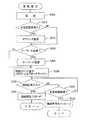
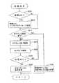
図6は、サーバ20のサーバ側プログラムP21の実行にて実現されるサーバ側処理の概略処理内容を示したフローチャートである。同図において、サーバ20は、最初に、複数のプロジェクタ301〜30nから接続可能なプロジェクタ301〜30nを検索するプロジェクタ検索処理を実行する(ステップS100)。接続可能なプロジェクタ301〜30nが検索されると、この接続可能なプロジェクタ301〜30nから、画像データを出力して画像表示させる所望のプロジェクタ301〜30nを選択するとともに、同選択した所望のプロジェクタ301〜30nとの接続を確立する接続確立処理を実行する(ステップS200)。そして、接続を確立したプロジェクタ301〜30nに、当該接続を確立したプロジェクタ301〜30nにて画像表示させるための画像データを出力する画像データ出力処理を実行する(ステップS300)。一方、プロジェクタ301〜30nに対する画像データの出力を行う必要が無くなった場合は、接続切断処理を実行して、接続を確立したプロジェクタ301〜30nとの接続を切断する(ステップS400)。(4) Processing contents of server side processing:
FIG. 6 is a flowchart showing the outline processing contents of the server-side processing realized by executing the server-side program P21 of the
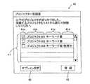
図7は、ステップS100のプロジェクタ検索処理の処理内容を示したフローチャートである。同図においては、最初に、IPアドレスが格納されているHDD27の所定の記憶領域を検索し、当該サーバ20にIPアドレスが設定されているか否かを判別する(ステップS105)。IPアドレスが設定されている場合は、このIPアドレスを組み込んだ検索コマンドをプロジェクタ301〜30nに出力する。このとき、UDPの通信プロトコルに基づいた同報通信によって検索コマンドの出力を行う(ステップS110)。そして、プロジェクタ301〜30nから出力される当該検索コマンドに対する検索応答が入力されるか否かを判別する(ステップS115)。検索応答が入力されない場合は、所定時間が経過するまでこの検索応答の入力を判別する(ステップS120)。ステップS115にて検索応答が入力されたと判別された場合は、図8に示すプロジェクタ一覧画面40を表示することによって、利用者に接続可能なプロジェクタ301〜30nを視認可能に提示する(ステップS130)。 FIG. 7 is a flowchart showing the processing contents of the projector search processing in step S100. In the figure, first, a predetermined storage area of the
この検索応答には、後述するように、検索応答を返信してきたプロジェクタ301〜30nの固有情報(MACアドレス等)や、プロジェクタ301〜30nの使用状況情報や、接続確立時にキーワードによる認証が必要になるか否かを示すキーワード情報が付加されている。ここで、プロジェクタ一覧画面40について説明する。図8において、プロジェクタ一覧画面40は、「以下のプロジェクタが見つかりました。・・・・」というメッセージが表示されるとともに、プロジェクタリスト41と、接続ボタン42と、オプション設定ボタン43とを有する構成となっている。また、プロジェクタリスト41は、選択チェックボックス41aと、プロジェクタ名称欄41bと、キーワード情報欄41cと、使用状況情報欄41dとから構成されている。 As will be described later, this search response requires unique information (MAC address or the like) of the
本実施形態においては、プロジェクタ301〜303が接続可能であることを示し、各プロジェクタ301〜303は接続に際して、キーワードの認証が必要であることを示し、プロジェクタ303については他のサーバによる接続が確立していて使用中であることを示している。一方、ステップS105にてIPアドレスが設定されていないと判別された場合は、ネットワーク設定変更が必要となる旨のメッセージを表示し、利用者にIPアドレスの設定を促す(ステップS135)。また、ステップS120にて検索応答が入力されないと判別された場合は、通信モードが異なる(インフラストラクチャモードではなく、アドホックモード)と判断され、無線LANの通信モードの設定をインフラストラクチャモードに変更する必要がある旨のメッセージを表示し、利用者に通信モードの変更を促す(ステップS140)。上述したステップS130にてプロジェクタ一覧画面40が表示されると、接続確立処理に移行する。 In the present embodiment, the
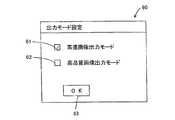
図9は、ステップS200の接続確立処理の処理内容を示したフローチャートである。同図において、接続を確立するに際して、利用者は、プロジェクタ一覧画面40のプロジェクタリスト41に表示されているプロジェクタ301〜303の中から所望のプロジェクタ301〜303を選択する。本実施形態においては、プロジェクタ301の選択チェックボックス41aにチェックを入力し、同プロジェクタ301を選択した場合を示している(ステップS205)。次に、IP指定接続が設定されているか否かを判別する(ステップS210)。このIP指定接続の設定は図8に示したプロジェクタ一覧画面40のオプション設定ボタン43が選択された場合に表示されるオプション設定画面にて設定が可能になっている。ここで、このオプション設定画面の画面構成を図10に示す。同図において、オプション設定画面50は、オプション設定のアイテムとして暗号化設定欄51と、IP指定接続設定欄52と、キーワード設定ボタン53と、出力モード設定ボタン54とを備える構成となっている。 FIG. 9 is a flowchart showing the contents of the connection establishment process in step S200. In the figure, when establishing a connection, the user selects desired
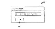
IP指定接続設定欄52は、接続するプロジェクタ301に特定のIPアドレスをサーバ20側の設定に基づいて設定する場合に選択するものであり、選択する場合はチェックボックス52aにチェックを入れることになる。本実施形態においては、チェックボックス52aがチェックされていない状態を示している。従って、かかる場合、プロジェクタ301のIPアドレスは、同プロジェクタ301にて実行されるプロジェクタ側処理によって設定されることになる。一方、チェックボックス52aにチェックが入れられて、IP指定接続が設定された場合は、利用者はIP指定接続設定欄52に含まれるIPアドレス設定ボタン52bを選択して図11に示すIPアドレス設定画面60を表示させ、所望のIPアドレスを入力することになる。ここで、利用者がIPアドレス設定画面60にて所望のIPアドレスを設定するとOKボタン61を選択する。これにより、プロジェクタ301に設定するための特定のIPアドレスが決定される(ステップS215)。次に、プロジェクタ301との接続を確立するに際して、キーワードによる認証が必要であるか否かを判別する(ステップS220)。 The IP designation
本実施形態においては、図8に示すとおり、プロジェクタ301のキーワード情報は「キーワード要」となっている。従って、利用者はオプション設定画面50のキーワード設定ボタン53を選択して、図12に示したキーワード設定画面70を表示させ、所定のキーワードを入力する(ステップS225)。かかる場合、このキーワードは後述するとおり、プロジェクタ301によって投影表示されるため、利用者はこの投影表示されたキーワードを視認してキーワード設定画面70に対して入力することになる。そして、OKボタン71が押し下げられキーワードの設定が完了した後に、利用者によってプロジェクタ一覧画面40の接続ボタン42が選択押し下げられると、設定されたキーワードを含んだ接続コマンドをプロジェクタ301〜30nに対して出力する(IP指定接続が設定されている場合は、この接続コマンドにIPアドレス設定画面60にて設定されたIPアドレスも含まれる)。 In the present embodiment, as shown in FIG. 8, the keyword information of the
かかる場合、まだTCP/IPに基づく接続が確立していないので、この接続コマンドは、UDPの通信プロトコルに基づいた同報通信によって出力が行われる(ステップS230)。そして、この接続コマンドに対するプロジェクタ301の接続応答が入力されるか否かを判別し(ステップS235)、接続応答が入力された場合は、TCP/IPに基づいてプロジェクタ301との接続を確立させる(ステップS240)。一方、ステップS235にて接続応答が入力されないで、所定時間経過した場合は(ステップS245)、接続不可のメッセージを表示して、その旨を利用者に通知する(ステップS250)。上述したステップS240にてプロジェクタ301との接続が確立すると、サーバ20とプロジェクタ301との間にて相互通信が開始され、サーバ20はプロジェクタ301に対して画像データを出力することが可能になり、次に説明する画像データ出力処理を実行する。 In this case, since the connection based on TCP / IP has not been established yet, this connection command is output by broadcast communication based on the UDP communication protocol (step S230). Then, it is determined whether or not a connection response of the
図13は、ステップS300の画像データ出力処理の処理内容を示したフローチャートである。同図において、先ず、ディスプレイ29に表示されている画像の画像データをVRAM24から入力するとともに(ステップS305)、所定時間経過後に(ステップS310)、再度VRAM24から画像データを入力する(ステップS315)。そして、ステップS305にて入力した画像データと、ステップS315にて入力した画像データとを比較してその差分を取る(ステップS320)。この差分が所定の閾値以上であるか否かに基づいて、ディスプレイ29に表示された画像に変化があるか否かを判別する(ステップS325)。差分が閾値より小さい場合は、画像が変化していないと判別して、ステップS305〜S320の処理を繰り返す。ステップS325にて画像に変化があったと判別された場合は、出力モードが高速画像出力モードであるか否かを判別する(ステップS330)。 FIG. 13 is a flowchart showing the processing contents of the image data output processing in step S300. In the figure, first, image data of an image displayed on the
この出力モードは、図10に示したオプション設定画面50の出力モード設定ボタン54を選択して、図14に示す出力モード設定画面60を表示させて設定することが可能になっている。図14において、出力モード設定画面60では、出力モードとして、高速画像出力モード61と、高品質画像出力モード62とが選択可能になっている。ここで、高速画像出力モード61は、画像が変化した場合に、変化した部分のみの画像データを出力することによって、高速化を図るモードであり、高品質画像出力モード62は、画像が変化した場合に、全画像データを出力し、画像の品質を保持することを図るモードである。利用者はいずれかのモード61,62を選択してOKボタン63を押し下げる。これによって、出力モードが設定される。ステップS330にて高速画像出力モードが設定されていると判別された場合は、VRAM24から変化した部分の画像データを取得する(ステップS335)。 This output mode can be set by selecting the output
一方、ステップS330にて高品質画像出力モードが設定されていると判別された場合は、VRAM24から全画像データを取得する(ステップS340)。変化した部分の画像データあるいは全画像データを取得すると、この取得した画像データを圧縮する(ステップS345)。画像データを圧縮すると、暗号化設定がなされているか否かを判別する(ステップS350)。この暗号化設定は、出力する画像データを暗号化するものである。かかる設定は、図10に示したオプション設定画面50の暗号化設定欄51にて設定可能であり、暗号化設定を行う場合、利用者はチェックボックス51aをチェックする。ステップS350にて暗号化設定がなされていると判別された場合は、圧縮した画像データの暗号化を行う(ステップS355)。 On the other hand, if it is determined in step S330 that the high-quality image output mode is set, all image data is acquired from the VRAM 24 (step S340). When the image data of the changed part or the entire image data is acquired, the acquired image data is compressed (step S345). When the image data is compressed, it is determined whether or not encryption is set (step S350). This encryption setting is for encrypting output image data. Such setting can be set in the
この暗号化は既存の技術を利用して実施する。一方、暗号化設定がなされていないと判別された場合は、暗号化を行わない。そして、暗号化された画像データあるいは暗号化されていない画像データをプロジェクタ301に対して出力する(ステップS360)。この画像データ出力処理では、サーバ20のディスプレイ29に表示されている画像に変化があった場合に、変化した部分の画像データのみを出力する。ここで、ステップS335にて変化した部分の画像データを取得し、この画像データをプロジェクタ301に出力した場合、プロジェクタ301は、この部分的な画像データを、保持している変化前の画像データに合成することによって、変化後の画像データを形成することになる。 This encryption is performed using existing technology. On the other hand, if it is determined that the encryption setting is not made, the encryption is not performed. Then, the encrypted image data or the unencrypted image data is output to the projector 301 (step S360). In this image data output process, when there is a change in the image displayed on the
変化した部分を取得する場合、あらかじめ画像を複数のブロックに分割しておき、変化した部分が含まれるブロックを送信するようにしてもよい。むろん、この場合は圧縮手法に応じてブロックの区切りを決めておけば、一つのブロックを送信しようとしたときに、圧縮する際の複数の領域にまたがってしまうことを防止でき、送信する画像データのサイズを低減させることができる。 When acquiring a changed portion, the image may be divided into a plurality of blocks in advance, and a block including the changed portion may be transmitted. Of course, if the block delimiter is determined according to the compression method in this case, when trying to transmit one block, it is possible to prevent the image data from being transmitted from being spread over multiple areas during compression. Can be reduced in size.
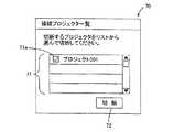
サーバ20の利用者は、プロジェクタ301の使用が終わった場合、サーバ20において、図15に示す接続プロジェクタ一覧画面70を表示する。同図において、接続プロジェクタ一覧画面70は、接続プロジェクタリスト71を備えており、利用者は切断対象のプロジェクタのチェックボックスをチェックして切断ボタン72を選択して押し下げる。すると、ステップS400の接続切断処理が実行されることになる。図16は、この接続切断処理の処理内容を示したフローチャートである。同図において、上述した接続プロジェクタ一覧画面70にて、切断ボタン72が選択されて押し下げられたか否かを判別する(ステップS405)。切断ボタン72が選択されて押し下げられたと判別された場合は、切断対象となっているプロジェクタ(本実施形態においてはプロジェクタ301)に設定されているIPアドレスを取得する(ステップS410)。そして、このIPアドレスを含めた切断コマンドを出力し(ステップS415)、プロジェクタ301から出力されるこの切断コマンドに対応した切断完了コマンドの入力の有無を判別する(ステップS420)。切断完了コマンドを入力した場合は、接続を切断する(ステップS425)。 When the use of the
(5)プロジェクタ側処理の処理内容:
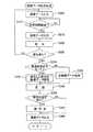
次に、プロジェクタ側プログラムP31の処理について説明する。図17は、プロジェクタ側処理の概略処理内容を示したフローチャートである。同図において、プロジェクタ301〜30nは、電源が投入されると、自プロジェクタ301〜30nにIPアドレスの仮設定を行う初期設定処理を実行する(ステップS500)。この初期設定処理が終了すると、サーバ20から出力される検索コマンドの待機状態に移行し、検索コマンドに対する応答を行う検索応答処理を実行する(ステップS600)。次に、サーバ20との接続を確立させる接続確立処理を実行し(ステップS700)、接続が確立したサーバ20から出力される画像データを表示する画像表示処理を実行する(ステップS800)。そして、サーバ20での接続切断に対応して、接続切断処理を実行する(ステップS900)。(5) Processing contents of the projector side processing:
Next, the process of the projector side program P31 will be described. FIG. 17 is a flowchart showing the outline processing contents of the projector-side processing. In the figure, when the power is turned on, the
図18は、ステップS500の初期設定処理の処理内容を示したフローチャートである。同図において、プロジェクタ301〜30nは電源が投入されると、ネットワークインターフェース33が無線LAN対応であるか否かを判別する(ステップS505)。無線LAN対応であると判別された場合は、通信モードをインフラストラクチャモードに設定する(ステップS510)。次に、プロジェクタ301〜30nはIPアドレスが設定されているか否かを判別し(ステップS515)、自己にIPアドレスが設定されていないと判別された場合は、所定のIPアドレスを仮々設定する(ステップS520)。そして、この仮々設定したIPアドレスに基づいてネットワーク上に競合するIPアドレスが設定されたネットワーク機器が存在するか否かを検索する(ステップS525)。 FIG. 18 is a flowchart showing the contents of the initial setting process in step S500. In the figure, when the power is turned on, the
この検索は、Pingコマンドにて実行され、仮々設定したIPアドレスと同一のIPアドレスが設定されたネットワーク機器が存在する場合は、このネットワーク機器から競合する旨の応答がある。従って、この応答の有無を判別する(ステップS530)。応答が無いと判別された場合は、この仮々設定したIPアドレスをプロジェクタ301〜30nに仮設定する(ステップS535)。一方、応答が有ったと判別された場合は、他のIPアドレスによって仮々設定し、競合するネットワーク機器が存在するか否かを判別し、競合するネットワーク機器が無くなるまで、IPアドレスの仮々設定による検索の処理を繰り返す。また、ステップS515にて既にIPアドレスが設定されていると判別された場合は、このIPアドレスをプロジェクタ301〜30nに仮設定する(ステップS540)。 This search is executed by the Ping command, and when there is a network device set with the same IP address as the temporarily set IP address, there is a response indicating that there is a conflict from this network device. Therefore, the presence or absence of this response is discriminated (step S530). If it is determined that there is no response, the provisionally set IP address is provisionally set in the
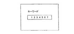
図19は、ステップS600の検索応答処理の処理内容を示したフローチャートである。同図において、ステップS500の初期設定処理が終了すると、プロジェクタ301〜30nはサーバ20から出力される検索コマンドの入力待機状態となり、この検索コマンドが入力されるか否かを判別しつつ待機する(ステップS605)。検索コマンドが入力されたと判別されると、サーバ20が該プロジェクタ301〜30nと接続を確立するためにキーワードによる認証が必要であるか否かを判別する(ステップS610)。このキーワードによる認証の要不要は、プロジェクタ301〜30nにおける設定によって決められる。キーワードによる認証が必要であると判別された場合は、キーワード表示処理を実行し、キーワードを投影表示してサーバ20の利用者に視認可能にする(ステップS615)。ここで、このキーワード表示処理の処理内容を図20のフローチャートに示す。同図において、表示するキーワードを生成するに際して、最初に、乱数処理を実行する(ステップS615a)。そして、この乱数処理に基づいて7桁の数字列からなるキーワードを生成し(ステップS615b)、この生成したキーワードを投影表示する(ステップS615c)。むろん、キーワードは数字列以外にも文字、記号などを含めて適宜変更可能である。すると、図21に示すような、キーワード表示画像がスクリーンに投影表示されることになる。サーバ20の利用者は、このスクリーンに投影表示されたキーワードを視認して、上述したステップS200における接続確立処理において、このキーワードを設定し、接続コマンドを出力することになる。ステップS615におけるキーワード表示処理が終了すると、プロジェクタ301〜303の固有情報(MACアドレス等)、使用状況情報(他のサーバとの接続状態であり、他のサーバと接続されている場合は「使用中」状態となり、接続されていない場合は「未使用」状態となる。この使用状況情報は図8に示したプロジェクタ一覧画面40に表示される)、キーワード情報(キーワードの要不要を示す)を含んだ検索応答を出力する(ステップS620)。なお、図8に示すとおり、本実施形態においては、プロジェクタ301〜303がこの検索応答を出力している。 FIG. 19 is a flowchart showing the processing contents of the search response processing in step S600. In the figure, when the initial setting process in step S500 is completed, the
図22は、ステップS700の接続確立処理の処理内容を示したフローチャートである。同図において、ステップS600の検索応答処理にてサーバ20に対して検索応答を出力すると、サーバ20によるこの検索応答に対する接続コマンドの入力待機状態となり、この検索コマンドが入力されるか否かを判別しつつ待機する(ステップS705)。サーバ20から接続コマンドを入力したと判別すると、接続コマンドに含まれている固有情報の判別を行う(ステップS710)。固有情報が一致していると判別した場合は、キーワードによる認証が必要であるか否かを判別し(ステップS715)、キーワードによる認証が必要であると場合は、接続コマンドに含まれているキーワードが一致(正常)するか否かを判別する(ステップS720)。 FIG. 22 is a flowchart showing the processing contents of the connection establishment processing in step S700. In the figure, when a search response is output to the
キーワードが一致していると判別した場合は、接続コマンドにIPアドレスの設定が含まれているか否かを判別する。接続コマンドにIPアドレスが設定されている場合とは、サーバ20にてIP指定接続が選択された場合を示している(ステップS725)。接続コマンドにIPアドレスが設定されていない場合は、所定のIPアドレスを設定し、このIPアドレスに基づいてネットワーク上に競合するIPアドレスが設定されたネットワーク機器が存在するか否かを検索する(ステップS730)。この検索は、Pingコマンドにて実行され、このIPアドレスと同一のIPアドレスが設定されたネットワーク機器が存在する場合は、このネットワーク機器から競合する旨の応答がある。従って、この応答の有無を判別する(ステップS530)。応答が無いと判別された場合は、ステップS730にて設定したIPアドレスをプロジェクタ301に本設定する(ステップS740)。一方、ステップS725にて接続コマンドにIPアドレスが設定されていると判別された場合は、このステップS740において、接続コマンドに設定されているIPアドレスをプロジェクタ301に本設定する。 If it is determined that the keywords match, it is determined whether or not an IP address setting is included in the connection command. The case where the IP address is set in the connection command indicates the case where the IP designated connection is selected by the server 20 (step S725). If no IP address is set in the connection command, a predetermined IP address is set, and it is searched based on this IP address whether there is a network device set with a conflicting IP address on the network ( Step S730). This search is executed by the Ping command, and when there is a network device set with the same IP address as this IP address, there is a response indicating that there is a conflict from this network device. Therefore, the presence or absence of this response is discriminated (step S530). If it is determined that there is no response, the IP address set in step S730 is fully set in the projector 301 (step S740). On the other hand, if it is determined in step S725 that the IP address is set in the connection command, the IP address set in the connection command is permanently set in the
一方、応答が有ったと判別された場合は、他のIPアドレスによって設定し、競合するネットワーク機器が存在するか否かを判別し、競合するネットワーク機器が無くなるまで、IPアドレスの検索の処理を繰り返す。IPアドレスの本設定が終了すると、サーバ20に対して接続応答を出力する(ステップS745)。これによって、サーバ20との間においてTCP/IPによる接続を確立し、同サーバ20と相互通信を開始する(ステップS750)。一方、ステップS710およびS720にて固有情報およびキーワードが一致しないと判別された場合は、接続不可を通知する旨のメッセージを投影表示してサーバ20の利用者によって視認可能にする(ステップS755)。上述したステップS750にてサーバ20と相互通信が開始されると、サーバ20から画像データを入力することが可能になるため、次に説明する画像表示処理を実行する。 On the other hand, if it is determined that there is a response, it is set by another IP address, it is determined whether there are competing network devices, and IP address search processing is performed until there are no competing network devices. repeat. When the final setting of the IP address is completed, a connection response is output to the server 20 (step S745). Thereby, a TCP / IP connection is established with the
図23は、画像表示処理の処理内容を示したフローチャートである。同図において、サーバ20からデータを入力するか否かを判別し(ステップS805)、データの入力が判別された場合は、このデータから画像データを抽出する(ステップS810)。この抽出した画像データは圧縮された画像データであるため、当該圧縮された画像データを解凍する(ステップS815)。次に、解凍した画像データが暗号化されているか否かを判別し(ステップS820)、暗号化されている場合は、この画像データを復号化する(ステップS825)。そして、この画像データに基づいて画像を表示する(ステップS830)。 FIG. 23 is a flowchart showing the processing contents of the image display processing. In the figure, it is determined whether or not data is input from the server 20 (step S805). If the input of data is determined, image data is extracted from this data (step S810). Since the extracted image data is compressed image data, the compressed image data is decompressed (step S815). Next, it is determined whether or not the decompressed image data is encrypted (step S820). If the decompressed image data is encrypted, the image data is decrypted (step S825). Then, an image is displayed based on the image data (step S830).
図24は、接続切断処理の処理内容を示したフローチャートである。同図において、サーバ20と確立された接続は、サーバ20での接続切断処理に対応して切断されることになる。そこで、先ず、サーバ20から出力される切断コマンドの入力を待機する(ステップS905)。切断コマンドを入力すると、プロジェクタ301内にて所定の切断処理を実行し(ステップS910)、サーバ20に対して、切断完了コマンドを出力する(ステップS915)。これによって、サーバ20との接続が切断されることになる(ステップS920)。 FIG. 24 is a flowchart showing the contents of the connection disconnection process. In the figure, the connection established with the
(6)変形例:
上述してきた実施形態においては、サーバ20とプロジェクタ301〜30nとを無線LANにて接続するプロジェクタシステム10について説明してきたが、むろん、無線LANのネットワークにおけるシステムに限定されるものではなく、有線LANのネットワークおよび無線LAN、有線LANを混合させたネットワークによってプロジェクタシステム10を構成しても良い。かかる場合、有線LANにIEEE1394等のネットワークとして機能するものを採用すればシステムを構築することが可能である。また、本実施形態においては、本発明にかかる画像データ伝送システムをプロジェクタシステムに適用する態様を採用したが、むろん、この画像データ伝送システムは、複数のコンピュータを有するシステムにおいても適用することが可能であることは言うまでもない。すなわち、本画像データ伝送システムによって、一つのコンピュータの画像データを他のコンピュータにて画像表示するシステムを構築することも可能である。(6) Modification:
In the above-described embodiment, the
(7)まとめ:
このように、サーバ20とプロジェクタ301〜30nとの接続を確立するに際して、最初にUDPの通信コマンドによって接続可能なプロジェクタ301〜303を検索し、その後に接続するプロジェクタ301を選択して、同プロジェクタ301にIPアドレスを設定して、画像データ等は信頼性のあるTCP/IPの通信コマンドにて入出力する接続を確立することによって、利用者は簡易にサーバ20とプロジェクタ301とを相互通信可能な接続環境を得ることが可能になる。また、接続確立時に投影表示されるキーワードによる認証を行うことによって、部外者によるプロジェクタ301に対する不正アクセスを防止することが可能になる。(7) Summary:
As described above, when establishing a connection between the
以上説明したように本発明は、簡易な手法でサーバとクライアントとの間において相互通信可能な接続を確立することができる画像データ伝送システム、画像データ伝送方法、画像データ伝送プログラムを提供することができる。 As described above, the present invention can provide an image data transmission system, an image data transmission method, and an image data transmission program capable of establishing a connection capable of mutual communication between a server and a client by a simple method. it can.
10…プロジェクタシステム、15,27…HDD、20…サーバ、21,31…CPU、22,32…ROM、23,34…RAM、24,35…VRAM、25,36…グラフィックコントローラ、26,33…ネットワークインターフェース、28,38…バス、29…ディスプレイ、30,301〜30n…プロジェクタ、35a…プロジェクタ表示装置、35b…プロジェクタインターフェース、37…EEPROM、40…プロジェクタ一覧画面、41…プロジェクタリスト、41a…選択チェックボックス、41b…プロジェクタ名称欄、41c…キーワード情報欄、41d…使用状況情報欄、42…接続ボタン、43…オプション設定ボタン、50…オプション設定画面、51…暗号化設定欄、51a,52a…チェックボックス、52…IP指定接続設定欄、52b…IPアドレス設定ボタン、53…キーワード設定ボタン、54…出力モード設定ボタン、M21,M32…通信モジュール、M22…画像データ出力モジュール、M23…ユーザーインターフェースモジュール、M31…表示モジュール、M33…ブラウザモジュール、P20,P30…オペレーティング・システム(OS)、P21…サーバ側プログラム、P31…プロジェクタ側プログラム、R…会議室。 DESCRIPTION OF
Claims (5)
Translated fromJapanese前記コンピュータからの検索コマンドに対して検索応答処理を行う検索応答手段と、
前記コンピュータからの接続コマンドに対して接続確立処理を行う接続確立手段と、
当該プロジェクタに備えられた前記コンピュータとの前記接続確立処理の際の認証に用いられるキーワードを前記スクリーンに投影表示させるキーワード投影手段と、
を備えたことを特徴とするプロジェクタ。A projector that projects and displays an image output from acomputer on a screen,
Search response means for performing a search response process in response to a search command from the computer;
Connection establishment means for performing connection establishment processing in response to a connection command from the computer;
And keywords projection means for a keywordto be used for authentication when the connection establishment processing with the computer provided tothe projector is projected and displayed on thescreen,
A projector comprising:
前記コンピュータからの検索コマンドに対して検索応答処理を行ない、A search response process is performed for a search command from the computer,
予め備えられた前記コンピュータとの前記接続確立処理の際の認証に用いられるキーワードを前記スクリーンに投影表示する制御方法。A control method for projecting and displaying a keyword used for authentication at the time of the connection establishment process with the computer provided in advance on the screen.
Priority Applications (1)
| Application Number | Priority Date | Filing Date | Title |
|---|---|---|---|
| JP2009030879AJP4407772B2 (en) | 2002-05-27 | 2009-02-13 | projector |
Applications Claiming Priority (2)
| Application Number | Priority Date | Filing Date | Title |
|---|---|---|---|
| JP2002152413 | 2002-05-27 | ||
| JP2009030879AJP4407772B2 (en) | 2002-05-27 | 2009-02-13 | projector |
Related Parent Applications (1)
| Application Number | Title | Priority Date | Filing Date |
|---|---|---|---|
| JP2004508005ADivisionJP4353096B2 (en) | 2002-05-27 | 2003-05-22 | Information processing system, information processing method, information processing program, image data output device, and image display device |
Related Child Applications (1)
| Application Number | Title | Priority Date | Filing Date |
|---|---|---|---|
| JP2009216796ADivisionJP4985734B2 (en) | 2002-05-27 | 2009-09-18 | Projector system, connection method, program, and information recording medium |
Publications (2)
| Publication Number | Publication Date |
|---|---|
| JP2009181583A JP2009181583A (en) | 2009-08-13 |
| JP4407772B2true JP4407772B2 (en) | 2010-02-03 |
Family
ID=29561276
Family Applications (6)
| Application Number | Title | Priority Date | Filing Date |
|---|---|---|---|
| JP2004508005AExpired - LifetimeJP4353096B2 (en) | 2002-05-27 | 2003-05-22 | Information processing system, information processing method, information processing program, image data output device, and image display device |
| JP2009030879AExpired - LifetimeJP4407772B2 (en) | 2002-05-27 | 2009-02-13 | projector |
| JP2009216796AExpired - LifetimeJP4985734B2 (en) | 2002-05-27 | 2009-09-18 | Projector system, connection method, program, and information recording medium |
| JP2012021011AExpired - LifetimeJP5252098B2 (en) | 2002-05-27 | 2012-02-02 | Projector system, connection method, program, and information recording medium |
| JP2012263249AExpired - LifetimeJP5617907B2 (en) | 2002-05-27 | 2012-11-30 | Image data transmission system, image data transmission method, image data transmission program, image data output device, and image display device |
| JP2014147449AWithdrawnJP2014207015A (en) | 2002-05-27 | 2014-07-18 | Image data transmission system, image data transmission method, image data transmission program, image data output device, and image display device |
Family Applications Before (1)
| Application Number | Title | Priority Date | Filing Date |
|---|---|---|---|
| JP2004508005AExpired - LifetimeJP4353096B2 (en) | 2002-05-27 | 2003-05-22 | Information processing system, information processing method, information processing program, image data output device, and image display device |
Family Applications After (4)
| Application Number | Title | Priority Date | Filing Date |
|---|---|---|---|
| JP2009216796AExpired - LifetimeJP4985734B2 (en) | 2002-05-27 | 2009-09-18 | Projector system, connection method, program, and information recording medium |
| JP2012021011AExpired - LifetimeJP5252098B2 (en) | 2002-05-27 | 2012-02-02 | Projector system, connection method, program, and information recording medium |
| JP2012263249AExpired - LifetimeJP5617907B2 (en) | 2002-05-27 | 2012-11-30 | Image data transmission system, image data transmission method, image data transmission program, image data output device, and image display device |
| JP2014147449AWithdrawnJP2014207015A (en) | 2002-05-27 | 2014-07-18 | Image data transmission system, image data transmission method, image data transmission program, image data output device, and image display device |
Country Status (9)
| Country | Link |
|---|---|
| US (4) | US7293071B2 (en) |
| EP (5) | EP2259186B1 (en) |
| JP (6) | JP4353096B2 (en) |
| KR (1) | KR100687974B1 (en) |
| CN (1) | CN1324491C (en) |
| AT (3) | ATE545088T1 (en) |
| DE (2) | DE60335153D1 (en) |
| TW (1) | TWI239767B (en) |
| WO (1) | WO2003100620A1 (en) |
Families Citing this family (49)
| Publication number | Priority date | Publication date | Assignee | Title |
|---|---|---|---|---|
| JP3707407B2 (en)* | 2001-08-28 | 2005-10-19 | セイコーエプソン株式会社 | Projector that projects password |
| US7293071B2 (en)* | 2002-05-27 | 2007-11-06 | Seiko Epson Corporation | Image data transmission system, process and program, image data output device and image display device |
| JP2004287160A (en)* | 2003-03-24 | 2004-10-14 | Seiko Epson Corp | Image display system, projector, image display method, projector control method, image display program, and projector control program |
| US7970833B2 (en)* | 2003-06-02 | 2011-06-28 | Seiko Epson Corporation | Image capture method, system and apparatus |
| US7945785B2 (en)* | 2003-06-02 | 2011-05-17 | Seiko Epson Corporation | Security of data over a network |
| JP2007519271A (en)* | 2003-07-08 | 2007-07-12 | コーニンクレッカ フィリップス エレクトロニクス エヌ ヴィ | System and method for providing a presentation |
| JP4176603B2 (en)* | 2003-09-24 | 2008-11-05 | 株式会社東芝 | Image display device, image display system, image display device selection method, and program |
| JP2005210284A (en) | 2004-01-21 | 2005-08-04 | Nec Viewtechnology Ltd | Projector selection system, projector selection method and program thereof |
| JP2005208823A (en)* | 2004-01-21 | 2005-08-04 | Seiko Epson Corp | Projector network system |
| JP4660100B2 (en)* | 2004-02-26 | 2011-03-30 | 三洋電機株式会社 | Server device |
| JP2005285091A (en)* | 2004-03-04 | 2005-10-13 | Sony Corp | Image display device, information terminal device, network system and network setting method |
| US20060026181A1 (en)* | 2004-05-28 | 2006-02-02 | Jeff Glickman | Image processing systems and methods with tag-based communications protocol |
| US7680087B2 (en)* | 2004-09-08 | 2010-03-16 | Canon U.S.A., Inc. | Wireless state machine and multiplexing method for concurrent ad-hoc and infrastructure mode service in wireless networking |
| US20060092125A1 (en)* | 2004-09-30 | 2006-05-04 | Kisley Richard V | Apparatus and method to authenticate local interface for network attached projector |
| US20060168661A1 (en)* | 2005-01-25 | 2006-07-27 | Kisley Richard V | Apparatus and method to implement data management protocols using a projector |
| US20070074040A1 (en)* | 2005-09-29 | 2007-03-29 | Nokia Corporation | Online authorization using biometric and digital signature schemes |
| JP5040341B2 (en) | 2006-04-04 | 2012-10-03 | セイコーエプソン株式会社 | Projector system |
| JP2007318650A (en)* | 2006-05-29 | 2007-12-06 | Funai Electric Co Ltd | Client/server system |
| JP2007334180A (en)* | 2006-06-19 | 2007-12-27 | Seiko Epson Corp | Image projection apparatus and control method thereof |
| CN101145998B (en)* | 2006-09-11 | 2010-09-29 | 联想(北京)有限公司 | Method and network for establishing radio projection network |
| KR20080054158A (en)* | 2006-12-12 | 2008-06-17 | 삼성전자주식회사 | Image forming apparatus and control method thereof |
| US20110019824A1 (en)* | 2007-10-24 | 2011-01-27 | Hmicro, Inc. | Low power radiofrequency (rf) communication systems for secure wireless patch initialization and methods of use |
| JP4891268B2 (en)* | 2008-01-15 | 2012-03-07 | キヤノン株式会社 | Communication device, control method, program, storage medium |
| JP5538680B2 (en)* | 2008-01-15 | 2014-07-02 | キヤノン株式会社 | Communication device, control method, program, storage medium |
| US8231233B2 (en)* | 2009-06-17 | 2012-07-31 | Motorola Mobility, Inc. | Portable electronic device and method of power management for same to accommodate projector operation |
| JP5353591B2 (en)* | 2009-09-15 | 2013-11-27 | 株式会社リコー | Projector, projector system, control method, and control program |
| US8052189B2 (en)* | 2009-12-01 | 2011-11-08 | Toyota Motor Engineering & Manufacturing North America, Inc. | Trim ring having reinforced snap posts |
| JP5724202B2 (en)* | 2010-04-02 | 2015-05-27 | セイコーエプソン株式会社 | Projector and image display method |
| JP5087666B2 (en) | 2010-09-30 | 2012-12-05 | 株式会社東芝 | Information processing apparatus and communication control method |
| RU2446457C1 (en) | 2010-12-30 | 2012-03-27 | Закрытое акционерное общество "Лаборатория Касперского" | System and method for remote administration of personal computers within network |
| US9767195B2 (en) | 2011-04-21 | 2017-09-19 | Touchstream Technologies, Inc. | Virtualized hosting and displaying of content using a swappable media player |
| JP2013097328A (en)* | 2011-11-04 | 2013-05-20 | Ricoh Co Ltd | Image display device, image display method, and program |
| US9166978B2 (en) | 2012-01-25 | 2015-10-20 | International Business Machines Corporation | Automatic resource provisioning for meeting collaboration |
| GB2500652B (en)* | 2012-03-28 | 2016-03-23 | Canon Kk | Method and device for improving configuration of communication devices in a video projection system comprising multiple wireless video projectors |
| JP6051760B2 (en)* | 2012-10-18 | 2016-12-27 | 株式会社リコー | Information processing system, information processing apparatus, and program |
| JP6448173B2 (en)* | 2013-03-14 | 2019-01-09 | キヤノン株式会社 | COMMUNICATION DEVICE, ITS CONTROL METHOD, PROGRAM |
| JP6249639B2 (en)* | 2013-05-30 | 2017-12-20 | キヤノン株式会社 | Image processing system, image processing apparatus, image processing method, and image processing program |
| JP5622899B2 (en)* | 2013-07-02 | 2014-11-12 | 株式会社東芝 | Display control apparatus and display control method |
| US9450910B2 (en) | 2014-02-06 | 2016-09-20 | Lenovo Enterprise Solutions (Singapore) Pte. Ltd. | Network address allocation |
| KR102254856B1 (en)* | 2014-09-23 | 2021-05-21 | 엘지전자 주식회사 | Computer system |
| JP6442230B2 (en)* | 2014-10-31 | 2018-12-19 | キヤノン株式会社 | Information processing apparatus, synchronization control method, and program |
| CN105657387A (en)* | 2015-12-30 | 2016-06-08 | 上海创功通讯技术有限公司 | Projection method and projection system |
| CN107894876B (en)* | 2016-10-03 | 2021-02-02 | 京瓷办公信息系统株式会社 | Information processing system and information processing method |
| US10560972B2 (en) | 2017-05-12 | 2020-02-11 | Canon Kabushiki Kaisha | Information processing apparatus, and control method thereof |
| JP6882059B2 (en)* | 2017-05-12 | 2021-06-02 | キヤノン株式会社 | Programs, methods, and equipment |
| KR102775449B1 (en)* | 2018-05-29 | 2025-02-28 | 소니그룹주식회사 | Projector, control method thereof and imaging system |
| CN111200725B (en)* | 2018-11-19 | 2023-09-26 | 中强光电股份有限公司 | Projector and starting method thereof |
| CN111221483B (en) | 2018-11-26 | 2023-07-04 | 中强光电股份有限公司 | Projector system and projector setting method |
| JP7670321B2 (en)* | 2021-05-21 | 2025-04-30 | Necプラットフォームズ株式会社 | Image monitoring device, method and program |
Family Cites Families (131)
| Publication number | Priority date | Publication date | Assignee | Title |
|---|---|---|---|---|
| US701695A (en)* | 1900-09-10 | 1902-06-03 | Emmery H Fahrney | Electric igniter for explosion-engines. |
| WO1998029832A1 (en)* | 1996-12-25 | 1998-07-09 | Sony Corporation | Image processor, data processor, and their methods |
| US4430526A (en)* | 1982-01-25 | 1984-02-07 | Bell Telephone Laboratories, Incorporated | Interactive graphics transmission system employing an adaptive stylus for reduced bandwidth |
| US4599489A (en)* | 1984-02-22 | 1986-07-08 | Gordian Systems, Inc. | Solid state key for controlling access to computer software |
| US4800590A (en)* | 1985-01-14 | 1989-01-24 | Willis E. Higgins | Computer key and computer lock system |
| US5572193A (en)* | 1990-12-07 | 1996-11-05 | Motorola, Inc. | Method for authentication and protection of subscribers in telecommunications systems |
| US6141000A (en)* | 1991-10-21 | 2000-10-31 | Smart Technologies Inc. | Projection display system with touch sensing on screen, computer assisted alignment correction and network conferencing |
| US5689641A (en)* | 1993-10-01 | 1997-11-18 | Vicor, Inc. | Multimedia collaboration system arrangement for routing compressed AV signal through a participant site without decompressing the AV signal |
| GB9321357D0 (en) | 1993-10-15 | 1993-12-22 | British Telecomm | Personal identification systems |
| JPH07200215A (en) | 1993-12-01 | 1995-08-04 | Internatl Business Mach Corp <Ibm> | Selection method of printing device and data processing network |
| EP0680174B1 (en)* | 1994-04-14 | 2002-08-28 | Kabushiki Kaisha Toshiba | Portable wireless computer terminal and method of controlling communication |
| US5782548A (en) | 1995-04-07 | 1998-07-21 | Seiko Epson Corporation | Image projection system and a method of controlling a projected pointer |
| US6148406A (en)* | 1995-04-27 | 2000-11-14 | Weisz; Herman | Access control password generated as a function of random numbers |
| JP3250418B2 (en)* | 1995-06-02 | 2002-01-28 | 松下電器産業株式会社 | Remote control system with pointing device |
| JPH09198206A (en)* | 1996-01-18 | 1997-07-31 | Ricoh Co Ltd | Network control system |
| JPH09205643A (en)* | 1996-01-29 | 1997-08-05 | Sony Corp | Remote supervisory equipment |
| US5768510A (en)* | 1996-07-01 | 1998-06-16 | Sun Microsystems, Inc. | Object-oriented system, method and article of manufacture for a client-server application enabler system |
| US6417933B1 (en)* | 1996-12-26 | 2002-07-09 | Lucent Technologies Inc. | Teleconferencing and facsimile communications system and method |
| US6699187B2 (en)* | 1997-03-27 | 2004-03-02 | Medtronic, Inc. | System and method for providing remote expert communications and video capabilities for use during a medical procedure |
| JP3864401B2 (en)* | 1997-04-23 | 2006-12-27 | ソニー株式会社 | Authentication system, electronic device, authentication method, and recording medium |
| JP3693475B2 (en)* | 1997-09-18 | 2005-09-07 | 株式会社日立コミュニケーションテクノロジー | Remote access router |
| AU2558899A (en) | 1998-01-16 | 1999-08-02 | Ameritech Corporation | System and method for providing secure remote access to a computer network |
| US6169976B1 (en)* | 1998-07-02 | 2001-01-02 | Encommerce, Inc. | Method and apparatus for regulating the use of licensed products |
| JP2000122829A (en)* | 1998-10-12 | 2000-04-28 | Fuji Xerox Co Ltd | Method and device for selecting printers |
| JP3658206B2 (en) | 1998-10-15 | 2005-06-08 | キヤノン株式会社 | Network device control apparatus and method |
| JP2000222163A (en)* | 1999-01-29 | 2000-08-11 | Seiko Epson Corp | Data display system and data display control method in data display system |
| US6345294B1 (en)* | 1999-04-19 | 2002-02-05 | Cisco Technology, Inc. | Methods and apparatus for remote configuration of an appliance on a network |
| JP3684108B2 (en) | 1999-06-11 | 2005-08-17 | キヤノン株式会社 | Network device management apparatus and method |
| JP3681577B2 (en)* | 1999-06-28 | 2005-08-10 | 株式会社デジタル | Control display device and recording medium on which program is recorded |
| JP3843662B2 (en)* | 1999-09-30 | 2006-11-08 | 株式会社日立製作所 | Network equipment and control system |
| JP2001175576A (en)* | 1999-10-04 | 2001-06-29 | Canon Inc | Information processing apparatus, information processing system, information processing method, and storage medium |
| US7403510B1 (en)* | 1999-11-10 | 2008-07-22 | Fujifilm Corporation | Communication terminal apparatus, communication method thereof, and connected destination selection method in wireless LAN |
| JP2001166758A (en)* | 1999-12-09 | 2001-06-22 | Seiko Epson Corp | Presentation support system and projector system |
| JP2001175602A (en) | 1999-12-20 | 2001-06-29 | Casio Comput Co Ltd | Communication terminal connection establishment method and communication system |
| US7177038B2 (en)* | 1999-12-28 | 2007-02-13 | Minolta Co., Ltd. | Image forming system |
| JP2001202316A (en)* | 2000-01-18 | 2001-07-27 | Canon Inc | Information processing apparatus, system and method, and storage medium |
| JP4688996B2 (en)* | 2000-01-31 | 2011-05-25 | キヤノン株式会社 | VIDEO DISPLAY DEVICE, ITS CONTROL METHOD, AND STORAGE MEDIUM |
| JP4520057B2 (en)* | 2000-02-16 | 2010-08-04 | 株式会社リコー | Output terminal |
| JP2001249784A (en)* | 2000-03-03 | 2001-09-14 | Canon Inc | Network device control method and apparatus |
| FI20000529A7 (en)* | 2000-03-08 | 2001-09-09 | Nokia Corp | Method for entering a key code into an electronic device and electronic device |
| JP2001255974A (en)* | 2000-03-13 | 2001-09-21 | Canon Inc | Information processing apparatus and method |
| JP2001290938A (en) | 2000-03-24 | 2001-10-19 | Trw Inc | Integrated digital production line for full-motion visual product |
| DE60131233D1 (en)* | 2000-03-27 | 2007-12-20 | Seiko Epson Corp | System to manage devices that are connected to a network |
| JP3750982B2 (en) | 2000-03-28 | 2006-03-01 | 三菱電機インフォメーションシステムズ株式会社 | User authentication system |
| JP2001285313A (en)* | 2000-03-31 | 2001-10-12 | Hittsu Kenkyusho:Kk | Data communication method and apparatus and recording medium recording data communication program |
| US7647555B1 (en)* | 2000-04-13 | 2010-01-12 | Fuji Xerox Co., Ltd. | System and method for video access from notes or summaries |
| JP2001296985A (en)* | 2000-04-17 | 2001-10-26 | Fuji Xerox Co Ltd | Information output system |
| JP3544918B2 (en)* | 2000-04-28 | 2004-07-21 | 株式会社東芝 | Wireless communication device and user authentication method |
| CN1142653C (en) | 2000-04-28 | 2004-03-17 | 杨宏伟 | Dynamic password authentication system and method |
| US6904529B1 (en)* | 2000-04-28 | 2005-06-07 | Microsoft Corporation | Method and system for protecting a security parameter negotiation server against denial-of-service attacks |
| US6760749B1 (en)* | 2000-05-10 | 2004-07-06 | Polycom, Inc. | Interactive conference content distribution device and methods of use thereof |
| JP2001331614A (en)* | 2000-05-19 | 2001-11-30 | Sony Corp | Network conference system, conference minutes generating method, conference managing server, and conference minutes generating method |
| WO2001089144A2 (en)* | 2000-05-19 | 2001-11-22 | Sony Corporation | Network conferencing system |
| JP2002057964A (en)* | 2000-05-31 | 2002-02-22 | Seiko Epson Corp | Projector and projection display system, and method and recording medium therefor |
| EP2278451A1 (en)* | 2000-05-31 | 2011-01-26 | Seiko Epson Corporation | Projector, projection display system, and corresponding method and recording medium |
| US6735616B1 (en)* | 2000-06-07 | 2004-05-11 | Infocus Corporation | Method and apparatus for remote projector administration and control |
| EP1980997A3 (en)* | 2000-06-09 | 2008-10-22 | Seiko Epson Corporation | Reproduction of an image using an image designation file |
| JP2001358919A (en) | 2000-06-13 | 2001-12-26 | Matsushita Electric Ind Co Ltd | Image display system, image display device, and recording medium |
| JP2002007091A (en) | 2000-06-22 | 2002-01-11 | Ricoh Co Ltd | Print server system |
| JP2002044096A (en)* | 2000-07-26 | 2002-02-08 | Toshiba Corp | Display device and display method |
| JP4304843B2 (en)* | 2000-08-02 | 2009-07-29 | 株式会社デンソー | Spark plug |
| JP2002074125A (en) | 2000-08-31 | 2002-03-15 | Sony Corp | Content distribution notification method, reservation management device, and program storage medium |
| JP2002099473A (en)* | 2000-09-25 | 2002-04-05 | Casio Comput Co Ltd | Method for collecting service information on network, service information collecting device on network, and recording medium storing service information collecting program on network |
| US6943752B2 (en) | 2000-09-28 | 2005-09-13 | Matsushita Electric Industrial Co., Ltd. | Presentation system, a display device, and a program |
| JP2002132640A (en)* | 2000-10-23 | 2002-05-10 | Canon Inc | Network system, server, service providing method, and storage medium |
| US6904451B1 (en)* | 2000-11-27 | 2005-06-07 | Eastman Kodak Company | Wireless networked presentation system |
| US7421082B2 (en)* | 2000-12-28 | 2008-09-02 | Sony Corporation | Data delivery method and data delivery system using sets of passkeys generated by dividing an encryption key |
| US7155163B2 (en)* | 2001-01-09 | 2006-12-26 | Agere Systems Inc. | Unified passcode pairing of piconet devices |
| JP2002222157A (en)* | 2001-01-29 | 2002-08-09 | Toshiba Corp | Electronic conference system |
| TWI225211B (en)* | 2001-02-15 | 2004-12-11 | Ibm | Security system for preventing a personal computer from being stolen or used by unauthorized people |
| JP3661601B2 (en)* | 2001-03-19 | 2005-06-15 | セイコーエプソン株式会社 | Image display by printing instructions |
| US6642918B2 (en) | 2001-04-23 | 2003-11-04 | Canon Kabushiki Kaisha | Control of digital projection system |
| US20020175915A1 (en) | 2001-05-23 | 2002-11-28 | Lichtfuss Hans A. | Internet image projector |
| US20030034999A1 (en) | 2001-05-31 | 2003-02-20 | Mindspeak, Llc | Enhancing interactive presentations |
| JP2002358284A (en) | 2001-06-01 | 2002-12-13 | Seiko Epson Corp | Service providing system and service providing device |
| US7180475B2 (en)* | 2001-06-07 | 2007-02-20 | Infocus Corporation | Method and apparatus for wireless image transmission to a projector |
| US20030017846A1 (en) | 2001-06-12 | 2003-01-23 | Estevez Leonardo W. | Wireless display |
| JP2003029201A (en)* | 2001-07-11 | 2003-01-29 | Canon Inc | Image projection device and image correction method |
| US20030028637A1 (en)* | 2001-07-31 | 2003-02-06 | Gross Curtis T. | Method and apparatus for providing network access to a shared image projection device |
| JP3707407B2 (en)* | 2001-08-28 | 2005-10-19 | セイコーエプソン株式会社 | Projector that projects password |
| JP3907162B2 (en)* | 2001-09-13 | 2007-04-18 | 株式会社東芝 | Presentation device |
| EP1427206A4 (en)* | 2001-09-14 | 2006-10-04 | Sony Corp | Information creation method, information creation apparatus, and network information processing system |
| US20050071430A1 (en)* | 2001-09-14 | 2005-03-31 | Youichi Kobayashi | Network information processing system and information processing method |
| US20070005809A1 (en) | 2001-09-14 | 2007-01-04 | Youichi Kobayashi | Network information processing system and network information processing method |
| JP4288879B2 (en)* | 2001-09-14 | 2009-07-01 | ソニー株式会社 | Network information processing system and information processing method |
| JP2003085112A (en)* | 2001-09-14 | 2003-03-20 | Sony Corp | Network information processing system, and information processing method |
| JP2003108423A (en)* | 2001-09-27 | 2003-04-11 | Sony Corp | Information processing system, client device forming the system, information providing server, and method for exclusive control of information providing server |
| KR100952860B1 (en) | 2001-09-28 | 2010-04-14 | 세이코 엡슨 가부시키가이샤 | Network projector interface system |
| US7237004B2 (en)* | 2001-10-17 | 2007-06-26 | Infocus Corporation | Dataconferencing appliance and system |
| TW519845B (en)* | 2001-10-31 | 2003-02-01 | Ru-Fang Shiau | Wireless projection system and projection method therefor |
| US20030088793A1 (en)* | 2001-11-06 | 2003-05-08 | Parry Travis J. | Managing customized menus across multiple imaging devices |
| US20030110217A1 (en)* | 2001-12-07 | 2003-06-12 | Raju Narayan D. | Method and apparatus for a networked projection system |
| JP4166466B2 (en)* | 2001-12-19 | 2008-10-15 | ソニー株式会社 | Wireless communication system and wireless communication method, wireless communication apparatus and control method thereof, and computer program |
| US7018043B2 (en)* | 2001-12-26 | 2006-03-28 | Infocus Corporation | Projector device user interface system |
| US6830340B2 (en)* | 2001-12-26 | 2004-12-14 | Infocus Corporation | Image-rendering device |
| JP3664132B2 (en)* | 2001-12-27 | 2005-06-22 | ソニー株式会社 | Network information processing system and information processing method |
| EP1329787B1 (en) | 2002-01-16 | 2019-08-28 | Texas Instruments Incorporated | Secure mode indicator for smart phone or PDA |
| JP2003224662A (en)* | 2002-01-30 | 2003-08-08 | Canon Inc | Conference system and its participation method |
| JP3610341B2 (en)* | 2002-02-19 | 2005-01-12 | キヤノン株式会社 | Network device and remote control relay server |
| US6957232B2 (en)* | 2002-04-05 | 2005-10-18 | Infocus Corporation | Projector control markup language |
| US20030198347A1 (en)* | 2002-04-22 | 2003-10-23 | Octalis Sa | System for handling digital rights and keys in business-to-business applications, computer software program, computer software modules and software products therefore |
| US20030204716A1 (en)* | 2002-04-24 | 2003-10-30 | Rockwood Troy Dean | System and methods for digital content distribution |
| US7209559B2 (en)* | 2002-04-29 | 2007-04-24 | The Boeing Company | Method and apparatus for securely distributing large digital video/data files with optimum security |
| US7349553B2 (en) | 2002-04-29 | 2008-03-25 | The Boeing Company | Watermarks for secure distribution of digital data |
| JP2003333559A (en) | 2002-05-08 | 2003-11-21 | Canon Inc | Conference system, conference management method, computer program, and computer-readable storage medium |
| US20030217293A1 (en)* | 2002-05-17 | 2003-11-20 | Lee Tony J. | System for permitting access to an electronic device when the password is not known |
| US7293071B2 (en) | 2002-05-27 | 2007-11-06 | Seiko Epson Corporation | Image data transmission system, process and program, image data output device and image display device |
| JP2004013283A (en)* | 2002-06-04 | 2004-01-15 | Hitachi Ltd | Content distribution method and content distribution device |
| CN1268122C (en)* | 2002-07-23 | 2006-08-02 | 精工爱普生株式会社 | Display system, network answering display device, terminal apparatus and controlling program |
| JP2004077967A (en)* | 2002-08-21 | 2004-03-11 | Sanyo Electric Co Ltd | Liquid crystal projector |
| CN100361823C (en) | 2002-08-30 | 2008-01-16 | 精工爱普生株式会社 | Printer, control method thereof, printing system, data receiving device, and data transceiving system |
| US20040073795A1 (en)* | 2002-10-10 | 2004-04-15 | Jablon David P. | Systems and methods for password-based connection |
| JP2004133354A (en)* | 2002-10-15 | 2004-04-30 | Seiko Epson Corp | Image display system, image display device, image data output device, image display method, image display program, and image data output program |
| US6901863B2 (en)* | 2002-11-27 | 2005-06-07 | Seiko Epson Corporation | Printer and print system for executing a proper print operation only in a place registered in advance |
| US6812994B2 (en)* | 2002-12-04 | 2004-11-02 | Eastman Kodak Company | Streamlined methods and systems for scheduling and handling digital cinema content in a multi-theatre environment |
| JP2004287160A (en)* | 2003-03-24 | 2004-10-14 | Seiko Epson Corp | Image display system, projector, image display method, projector control method, image display program, and projector control program |
| US6783252B1 (en) | 2003-04-21 | 2004-08-31 | Infocus Corporation | System and method for displaying projector system identification information |
| US7363508B2 (en)* | 2003-05-21 | 2008-04-22 | Palo Alto Research Center Incorporated | System and method for dynamically enabling components to implement data transfer security mechanisms |
| US7434166B2 (en)* | 2003-06-03 | 2008-10-07 | Harman International Industries Incorporated | Wireless presentation system |
| JP2007519271A (en)* | 2003-07-08 | 2007-07-12 | コーニンクレッカ フィリップス エレクトロニクス エヌ ヴィ | System and method for providing a presentation |
| US20050043973A1 (en)* | 2003-08-21 | 2005-02-24 | Winthrop Childers | Projector reservation system and method |
| US20050097179A1 (en)* | 2003-09-16 | 2005-05-05 | Orme Gregory M. | Spam prevention |
| JP2005099574A (en)* | 2003-09-26 | 2005-04-14 | Nec Viewtechnology Ltd | System for correcting geometrical optical center linked with lens shift |
| US8260857B2 (en)* | 2003-10-23 | 2012-09-04 | Microsoft Corporation | One to many data projection system and method |
| US20050091359A1 (en)* | 2003-10-24 | 2005-04-28 | Microsoft Corporation | Systems and methods for projecting content from computing devices |
| US20050134523A1 (en) | 2003-12-17 | 2005-06-23 | International Business Machines Corporation | Creating an encrypted channel to a wireless video display |
| JP2005208823A (en)* | 2004-01-21 | 2005-08-04 | Seiko Epson Corp | Projector network system |
| JP2005285091A (en) | 2004-03-04 | 2005-10-13 | Sony Corp | Image display device, information terminal device, network system and network setting method |
| JP2005285087A (en) | 2004-03-04 | 2005-10-13 | Sony Corp | Image display apparatus, image display system and image display method |
| US7370978B2 (en)* | 2005-05-09 | 2008-05-13 | Anderson Daryl E | Encrypting data |
| JP2007312179A (en)* | 2006-05-19 | 2007-11-29 | Seiko Epson Corp | Image display system, image display device of the image display system, portable terminal device, and connection establishment method in image display system |
- 2003
- 2003-05-21USUS10/442,056patent/US7293071B2/ennot_activeExpired - Lifetime
- 2003-05-22ATAT10177911Tpatent/ATE545088T1/enactive
- 2003-05-22KRKR20047016196Apatent/KR100687974B1/ennot_activeExpired - Lifetime
- 2003-05-22EPEP20100177908patent/EP2259186B1/ennot_activeExpired - Lifetime
- 2003-05-22EPEP20080075273patent/EP1967960B1/ennot_activeExpired - Lifetime
- 2003-05-22DEDE60335153Tpatent/DE60335153D1/ennot_activeExpired - Lifetime
- 2003-05-22WOPCT/JP2003/006431patent/WO2003100620A1/enactiveApplication Filing
- 2003-05-22ATAT03730595Tpatent/ATE479945T1/ennot_activeIP Right Cessation
- 2003-05-22EPEP20100177911patent/EP2259188B1/ennot_activeExpired - Lifetime
- 2003-05-22JPJP2004508005Apatent/JP4353096B2/ennot_activeExpired - Lifetime
- 2003-05-22CNCNB038118572Apatent/CN1324491C/ennot_activeExpired - Lifetime
- 2003-05-22ATAT08075273Tpatent/ATE489676T1/ennot_activeIP Right Cessation
- 2003-05-22EPEP20030730595patent/EP1501016B1/ennot_activeExpired - Lifetime
- 2003-05-22EPEP20100177910patent/EP2259187B1/ennot_activeExpired - Lifetime
- 2003-05-22DEDE60333992Tpatent/DE60333992D1/ennot_activeExpired - Lifetime
- 2003-05-26TWTW92114160Apatent/TWI239767B/ennot_activeIP Right Cessation
- 2007
- 2007-09-24USUS11/902,616patent/US7735130B2/ennot_activeExpired - Lifetime
- 2009
- 2009-02-13JPJP2009030879Apatent/JP4407772B2/ennot_activeExpired - Lifetime
- 2009-09-18JPJP2009216796Apatent/JP4985734B2/ennot_activeExpired - Lifetime
- 2009-12-01USUS12/628,654patent/US8875053B2/ennot_activeExpired - Lifetime
- 2012
- 2012-02-02JPJP2012021011Apatent/JP5252098B2/ennot_activeExpired - Lifetime
- 2012-11-30JPJP2012263249Apatent/JP5617907B2/ennot_activeExpired - Lifetime
- 2014
- 2014-06-30USUS14/319,261patent/US20140317725A1/ennot_activeAbandoned
- 2014-07-18JPJP2014147449Apatent/JP2014207015A/ennot_activeWithdrawn
Also Published As
Similar Documents
| Publication | Publication Date | Title |
|---|---|---|
| JP4407772B2 (en) | projector | |
| JP2003244183A (en) | Network equipment and remote control relay server | |
| JP2002055896A (en) | Communication systems and equipment | |
| JP2007323327A (en) | Network device, information processing apparatus, and program | |
| JP6344907B2 (en) | Information processing apparatus, system, and control method for information processing apparatus | |
| JP3531419B2 (en) | Image input method | |
| JP4328972B2 (en) | Printing system | |
| JP7494522B2 (en) | Communication Systems and Electronic Devices | |
| JP7365175B2 (en) | Information processing device, method, program | |
| JP2025075349A (en) | Information processing device, information processing method, and program | |
| JP2022182486A (en) | Communication device and computer program for communication device | |
| WO2024232290A1 (en) | Information processing device, method, and program | |
| JP2005250694A (en) | Information processing apparatus and information processing method | |
| JP2007199790A (en) | Device management system and device management method |
Legal Events
| Date | Code | Title | Description |
|---|---|---|---|
| A131 | Notification of reasons for refusal | Free format text:JAPANESE INTERMEDIATE CODE: A131 Effective date:20090722 | |
| A521 | Request for written amendment filed | Free format text:JAPANESE INTERMEDIATE CODE: A523 Effective date:20090918 | |
| TRDD | Decision of grant or rejection written | ||
| A01 | Written decision to grant a patent or to grant a registration (utility model) | Free format text:JAPANESE INTERMEDIATE CODE: A01 Effective date:20091020 | |
| A01 | Written decision to grant a patent or to grant a registration (utility model) | Free format text:JAPANESE INTERMEDIATE CODE: A01 | |
| A61 | First payment of annual fees (during grant procedure) | Free format text:JAPANESE INTERMEDIATE CODE: A61 Effective date:20091102 | |
| R150 | Certificate of patent or registration of utility model | Ref document number:4407772 Country of ref document:JP Free format text:JAPANESE INTERMEDIATE CODE: R150 Free format text:JAPANESE INTERMEDIATE CODE: R150 | |
| FPAY | Renewal fee payment (event date is renewal date of database) | Free format text:PAYMENT UNTIL: 20121120 Year of fee payment:3 | |
| FPAY | Renewal fee payment (event date is renewal date of database) | Free format text:PAYMENT UNTIL: 20121120 Year of fee payment:3 | |
| FPAY | Renewal fee payment (event date is renewal date of database) | Free format text:PAYMENT UNTIL: 20131120 Year of fee payment:4 | |
| S531 | Written request for registration of change of domicile | Free format text:JAPANESE INTERMEDIATE CODE: R313531 | |
| R350 | Written notification of registration of transfer | Free format text:JAPANESE INTERMEDIATE CODE: R350 | |
| EXPY | Cancellation because of completion of term |