JP4407044B2 - Combustion pressure sensor structure - Google Patents
Combustion pressure sensor structureDownload PDFInfo
- Publication number
- JP4407044B2 JP4407044B2JP2000358188AJP2000358188AJP4407044B2JP 4407044 B2JP4407044 B2JP 4407044B2JP 2000358188 AJP2000358188 AJP 2000358188AJP 2000358188 AJP2000358188 AJP 2000358188AJP 4407044 B2JP4407044 B2JP 4407044B2
- Authority
- JP
- Japan
- Prior art keywords
- combustion pressure
- pressure sensor
- nut
- sensor
- engine
- Prior art date
- Legal status (The legal status is an assumption and is not a legal conclusion. Google has not performed a legal analysis and makes no representation as to the accuracy of the status listed.)
- Expired - Fee Related
Links
Images


Classifications
- F—MECHANICAL ENGINEERING; LIGHTING; HEATING; WEAPONS; BLASTING
- F23—COMBUSTION APPARATUS; COMBUSTION PROCESSES
- F23Q—IGNITION; EXTINGUISHING-DEVICES
- F23Q7/00—Incandescent ignition; Igniters using electrically-produced heat, e.g. lighters for cigarettes; Electrically-heated glowing plugs
- F23Q7/001—Glowing plugs for internal-combustion engines
- F23Q2007/002—Glowing plugs for internal-combustion engines with sensing means
Landscapes
- Measuring Fluid Pressure (AREA)
- Ignition Installations For Internal Combustion Engines (AREA)
- Combined Controls Of Internal Combustion Engines (AREA)
Description
Translated fromJapanese【0001】
【発明の属する技術分野】
本発明は、エンジンルーム内に配設されたエンジンに取り付られる構造体(例えばグロープラグ、スパークプラグ、インジェクタ、ボルト等)と、該構造体に取り付けられてエンジンの燃焼圧を検出するための燃焼圧センサと、を備える燃焼圧センサ構造体に関する。
【0002】
【従来の技術】
この種の燃焼圧センサ構造体としては、例えば特開平7−139736号公報に記載されているようなディーゼル機関等のエンジンに始動補助装置として使用されている燃焼圧センサ付きグロープラグが提案されている。このものは、車両のディーゼルエンジンに取り付けられ、通電により発熱する発熱体を備えた構造体としてのプラグ本体部(グローヒータ)と、該プラグ本体部に作用する燃焼圧に伴う力を圧電セラミックス(圧電素子)の圧電特性に基づく電気信号に変換する燃焼圧センサ(圧力センサ)とを、備えた構成を有する。
【0003】
このような構成においては、エンジン内で発生した燃焼圧を、エンジンに取り付けられたプラグ本体部の変位として検知するようになっており、この変位が燃焼圧センサの圧電セラミックスへは、締め付け力による軸荷重の変動として伝達されて、電気信号に変換され燃焼圧として出力されるようになっている。そして、この出力信号(燃焼圧)は、該センサから延びる配線部材を介してエンジンルーム外部に配設された外部回路(車両のECU等)に入力され、エンジンの各種制御に供される。
【0004】
【発明が解決しようとする課題】
しかしながら、一般に、圧電セラミックスのインピーダンスは数百KΩ〜数十MΩと極めて高いため、燃焼圧センサにおける圧電セラミックスから発生した電荷は、塵・水・或るいは結露等によって、ケースや他の配線へ容易にリークする。そのため、燃焼圧センサからの出力信号は、外部回路へ至る途中で著しく分圧され、結果として出力信号は減衰する。
【0005】
また、燃焼圧センサにおいては、圧電セラミックスの特性上、出力信号は極めて微弱であるため、出力信号の減衰を最大限抑制することが必要であり、かつ、外部回路に至る入力信号(燃焼圧センサからの出力信号)に対しては耐電気ノイズ性を考慮する必要がある。
【0006】
ここで、従来では、エンジンルーム外部に設けられた外部回路近傍に増幅手段を設け、この増幅手段にて該センサからの出力信号を増幅しており、該センサから増幅手段に至る配線部材は長いもの(例えば1m〜2m)となるため、該センサの微弱な出力信号に電気的ノイズがのりやすい。
【0007】
ちなみに、耐電気ノイズ性の観点から、最近ディーゼルエンジンにおいても電子化が進んでおり、中でも燃料噴射をつかさどるインジェクタも例外ではなく、急速に電磁化が導入されている。その結果、例えば、燃焼圧センサに近接しているインジェクタでは、十数アンペアもの電流が流れ、その作動時の電流変化に伴うワイヤ並走ノイズ、又はヘッドランプやハザードランプから発生するリレー接点ノイズ、外部からの誘導ノイズ等、至る所に電気ノイズ発生源は点在しており、センサの出力信号に対する電気ノイズ対策の必要性は言うまでもない。
【0008】
なお、このような問題は、燃焼圧センサ付きグロープラグのみならず、エンジンルーム内に配設されたエンジンに取り付られる構造体(例えばスパークプラグ、インジェクタ、ボルト等)と、該構造体に取り付けられてエンジンの燃焼圧を電気信号に変換する燃焼圧センサと、を備える燃焼圧センサ構造体においては、共通の問題として発生すると考えられる。
【0009】
そこで、本発明は上記問題に鑑み、エンジンに取り付られる構造体と、該構造体に取り付けられてエンジンの燃焼圧を電気信号に変換する燃焼圧センサとを備える燃焼圧センサ構造体において、燃焼圧センサの出力信号の減衰を抑制するとともに、該出力信号に対する電気的ノイズを低減することを目的とする。
【0012】
【課題を解決するための手段】
本発明者等は、燃焼圧センサの出力信号を該センサの近傍にて増幅することに着目し、上記目的を解決する手段を創作するに至った。即ち、請求項1の発明においては、燃焼圧センサ(600)と圧電素子(321)からの電気信号を増幅する増幅手段(410)とを樹脂にてモールドし、一体化・内蔵し、
燃焼圧センサ(600)はセンサ固定部(310)を有し、
センサ固定部(310)は、構造体(200、700、800、900)の取り付けねじ(201a)にねじ結合される固定ナット(318)と、固定ナット(318)と別体になっている押さえ部(319)とから構成され、
圧電素子(321)及び増幅手段(410)は、センサ固定部(310)のうち押さえ部(319)側に一体化されており、
固定ナット(318)の締め付けを行っていない状態では、押さえ部(319)が圧電素子(321)及び増幅手段(410)とともに構造体の取り付けねじ(201a)の軸回りに自由に回転可能な構成となっており、
固定ナット(318)を回転させて取り付けねじ(201a)にねじ結合することで、固定ナット(318)の軸力により燃焼圧センサ(600)を構造体に取り付けることを特徴としている。
【0013】
それによって、増幅手段が燃焼圧センサ自身に内蔵されているため、燃焼圧センサの出力信号を該センサ内にて増幅することにより、該センサの出力信号の減衰を抑制できるとともに、該センサと増幅手段との間をつなぐ配線部材を不要とできるから、該出力信号に対する電気的ノイズを低減することができる。
しかも、固定ナット(318)を回転させるのみで燃焼圧センサ(600)の取り付けを行うことができるので、固定ナット(318)の回転によるセンサ装着に伴う必要空間を削減できる。
【0016】
また、請求項2の発明では、上記請求項1の発明における増幅手段(410)を、電気的にシールドされたものとしたことを特徴としている。これによれば、圧電素子からの電気信号(燃焼圧センサの出力信号)に対してより電気的ノイズがのりにくくできる。
【0018】
また、請求項3の発明では、請求項1または請求項2の発明における増幅手段(410)に、圧電素子(321)からの電気信号中の電気的ノイズを除去するためのフィルタ回路(416、417)を持たせたことを特徴としており、圧電素子からの電気信号(燃焼圧センサの出力信号)に対する電気的ノイズを効果的に除去することができる。
【0020】
なお、上記各手段の括弧内の符号は、後述する実施形態に記載の具体的手段との対応関係を示す一例である。
【0021】
【発明の実施の形態】
(第1実施形態)
本実施形態は、本発明の燃焼圧センサ構造体を、燃焼圧センサ付きグロープラグに具体化したものとして説明する。図1は、第1実施形態に係る燃焼圧センサ付きグロープラグ100の全体概略をディーゼルエンジンのエンジンヘッド(本発明でいう内燃機関の被取付部)1へ取り付けた状態にて示す一部縦断面図である。
【0022】
グロープラグ100は、大きくは、発熱体を備えかつ燃焼圧伝達の媒体を果たすプラグ本体部(本発明でいう構造体)200と、エンジンの燃焼圧に伴いプラグ本体部200に作用する力(プラグ本体部の歪み変位)を圧電素子の圧電特性に基づく電気信号に変換する手段である燃焼圧センサ300と、上記圧電素子からの電気信号を増幅する増幅手段を内蔵し外部回路(本実施形態では車両のECU)へ電気的接続が可能なコネクタ400と、該コネクタ400と燃焼圧センサ300とを電気的に接続する配線部材としてのリード線500と、を備えて構成されている。
【0023】
エンジンヘッド1には、各気筒毎に外表面から内部の燃焼室1aまで貫通するねじ穴(グローホール)が形成されており、各ねじ穴に対して、プラグ本体部200は、プラグの軸方向(長手方向)に挿入されている。プラグ本体部200は、金属製の中空パイプ状のハウジング201を有し、その外周面に形成された取付ねじ201aにおいてエンジンヘッド1のねじ穴とねじ結合されて固定されている。
【0024】
プラグ本体部(構造体)200は、ハウジング201内に保持された中空パイプ状のシース管202を備える。このシース管202は耐熱・耐食性合金(例えばステンレス材SUS310等)よりなり、先端側(図1中の下方側)が閉塞され他端側(図1中の上方側)が開口している。シース管202の先端側内部には、NiCr及びCoFe等の抵抗線からなる発熱コイル203が設けられ、シース管202の他端側内部には、金属製棒状の中軸204の一端側が一部挿入された形で配置されている。
【0025】
発熱コイル203の一端はシース管202の先端側に結合し、発熱コイル203の他端は中軸204の一端に結合している。また、発熱コイル203及び中軸204とシース管202との間には、耐熱性を有する酸化マグネシウム等の絶縁粉末205が充填されている。
【0026】
シース管202はスウェージングによる絞り加工が施されており、それによって、内部に充填された絶縁粉末205の緻密性を高めると共に、該絶縁粉末205を介してシース管202と中軸204及び発熱コイル203とが強固に保持固定されている。
【0027】
ここで、シース管202のうち発熱コイル203を包含する部分において、これらシース管202、発熱コイル203及び絶縁粉末205により、発熱体206が構成されている。そして、発熱体206は、その先端部(シース管202の先端部)が露出するように、ハウジング201の内部に接合保持されている。発熱体206(シース管202の外周面)とハウジング201との接合は、嵌合圧入による固着または銀ロウ等のロウ付けにより行うことができる。
【0028】
また、ハウジング201の上端側の内部において、絶縁性のべークライト材からなるワッシャ207、シリコン又はフッ素ゴムからなるOリング208が、中軸204に挿入配置されている。ここで、ワッシャ207は中軸204の芯出しを目的としたもので、Oリング208はハウジング201内の防水・気密性確保を目的としたものである。
【0029】
そして、中軸204は、フェノール等の絶縁樹脂からなる絶縁ブッシュ209を介在して、中軸204に設けられた端子ねじ204aに沿って固定ナット210にて、ハウジング201へ固定されている。ここで、絶縁ブッシュ209は中軸204とハウジング201との接触による短絡防止機能を兼ね備えている。
【0030】
また、中軸204の他端側に設けられた端子ねじ204aには、コネクティングバー2が端子ナット211によって固定され電気的に接続されている。このコネクティングバー2は図示しない電源に接続され、中軸204、発熱コイル203、シース管202、ハウジング201を介してエンジンヘッド1にアースされている。これにより、グロープラグ100において発熱体206は発熱し、ディーゼルエンジンの着火始動補助を行うことが可能となっている。
【0031】
なお、発熱体206は、上記した金属抵抗線を基本としたいわゆる金属発熱体の他に、例えば、窒化珪素と珪化モリブデンを成分とした導電性セラミックスからなる発熱体を、窒化珪素を成分とした絶縁性セラミックからなる絶縁体で内包する形で焼結した、いわゆるセラミック発熱体でも良い。
【0032】
次に、燃焼圧センサ300は全体が略リング状をなすもので、図1に示す様に、プラグ本体部(構造体)200におけるエンジンヘッド1の表面から軸方向へ突出した部分において、該突出部の外周面に固定されるとともに、エンジンヘッド1の表面に接触するように配置されている。図2は、図1中の燃焼圧センサ(圧力センサ)300の詳細を示す拡大図であり、(a)は縦断面図、(b)は(a)中のA矢視図を示している。
【0033】
燃焼圧センサ300は、大きくは、センサ本体をプラグ本体部(構造体)200に取り付けるためのナット(センサ固定部)310と、燃焼圧に伴う力に応じて電気信号(電荷)を発生する圧電素子部320と、この圧電素子部320にて発生した電気信号を取出しリード線500に導くためのリード部330と、ナット310とともに圧電素子部320を挟持し且つリード部330の一部を固定するための台座340と、圧電素子部320の防塵、防水を図るためのメタルケース350とを備えている。
【0034】
まず、ナット310及びリード部330について述べる。ナット310は金属製であり、プラグ本体部200のハウジング201に設けられた取付ねじ201aを介してセンサ本体を装着固定するためのねじ部311及び六角部312を備え、ハウジング201の外周に固定されている。また、六角部312の下側は、順に大径部313、小径部314が形成されており、小径部314の外周面には、シリコンからなる熱収縮性の絶縁チューブ315が密着固定されている。
【0035】
リード部330は、圧電素子部320とリード線500の一端側とを電気的に接続するための部分であり、電極331、インシュレータ332、固定金具333及びリード線500の一端側を、その構成要素として備えている。
【0036】
電極331は環状で金属製のものであり、インシュレータ332はこの電極331とナット310との間に介在して両者331及び310を互いに絶縁するもので、環状でマイカ或るいはアルミナ等の絶縁性材料よりなる。これら電極331及びインシュレータ332は、絶縁チューブ315で被覆されたナット310の小径部314の外縁に嵌入されている。
【0037】
ここで、リード線500は、その最内部から外側にかけて、導電性の信号取出線501、絶縁性の絶縁被覆502、導電性のアース側シールド線503、絶縁性の絶縁被覆504が順次と積層された構成を有し、信号取出線501とアース側シールド線503とは電気的に絶縁されている。そして、図2に示す様に、リード線500は、その一端側において先端から順に、信号取出線501、絶縁被覆502、アース側シールド線503が、それぞれ一部露出した構成となっている。
【0038】
そして、リード線500の一端側では、信号取出線501が、ナット310に形成された穴316及びインシュレータ332に形成された切欠き部332aを通して、電極331に形成された穴331aにて電極331に溶接され結線されている。なお、リード線500の他端側は、後述の図5(a)に示す様に、コネクタ400に接続されている。
【0039】
また、固定金具333は、リード線500をナット310に固定するためのもので中空パイプ状をなし、リード線500の一端側の外周に設けられている。ここで、ナット310に形成された上記穴316の上側部分は、固定金具333を保持するための固定金具保持穴316aとして構成されており、この保持穴316aには、固定金具333の一部が挿入固定されている。
【0040】
固定金具333はリード線500にかしめ固定されており、アース側シールド線503と固定金具333は電気的に接続されている。なお、固定金具保持穴316aから突き出た固定金具333の外周部分はシリコンからなる熱収縮性の絶縁被覆333aにて被覆されている。
【0041】
次に、圧電素子部320は、その中空部がナット310の小径部314に対応した円環状をなし、上記電極331と同様、該小径部314の外周面に沿って上記絶縁チューブ315を介して配設されている。ここで、図3に、圧電素子部320の詳細説明図を示す。図3において、(a)は信号取出側ワッシャリング322の単体斜視図、(b)は圧電素子部320の拡大縦断面図である。
【0042】
図3(b)に示す様に、圧電素子部320は、3層の圧電セラミックス(本発明でいう圧電素子)321を、信号取出側ワッシャリング322及びアース側ワッシャリング323と組合わせた積層構造を構成している。各圧電セラミックス321は同一寸法の円盤リング状をなし、チタン酸鉛、チタン酸ジルコン酸鉛等からなる。
【0043】
また、信号取出側ワッシャリング322は、図3(a)に示す様に、薄い円環状の同一の金属板322a、322bを上下2枚に配置し、少なくとも一部を円環の外縁側面部322cで結合されるようプレス加工によって製作されたものである。
【0044】
また、アース側ワッシャリング323も、信号取出ワッシャリング322と、同じく前記同様の形状・製造法で製作され、図3(b)及び図2(a)に示す様に、薄い円環状の同一の金属板323a、323bを上下2枚に配置し、少なくとも一部を円環の外縁側面部323c(図2(a)参照)で結合されたものである。
【0045】
そして、圧電素子部320においては、図3(b)に示す様に、金属板322a、圧電セラミックス321、金属板323a、圧電セラミックス321、金属板322b、圧電セラミックス321、金属板323bの順に、両ワッシャリング322、323の外縁側面部322cと323cとが接触しないよう積層状に配置されている。
【0046】
次に、ナット310とともに圧電素子部320を挟持し且つリード部330の一部を固定するための台座340は、金属製からなる略円環状をなす。台座340は、エンジンヘッド1との接触側端面に、図2(b)に示す様に、ナット310の小径部314の末端に形成された小判状の回り止め317に対応し、且つ、この回り止め317に容易に嵌合可能な同様の小判状の回り止め受け341が形成されている。
【0047】
また、台座340の外縁には、例えばSUS304からなる金属製円筒状のメタルケース350が設けられており、このメタルケース350により燃焼圧センサ300全体の外周が包含されている。このメタルケース350は、厚さ0.5mm以下の薄い金属板を円筒状に絞り加工し製作したもので、台座340に対して全周、レーザー溶接又は銅ロウ等のロウ付けで接合されている。
【0048】
このメタルケース350との一体化を図った台座340においては、その回り止め受け341とナット310の回り止め317とが正確に対向している。さらに、台座340の内径部342と、ナット310の小径部314の中央付近に設けた切欠き溝に嵌着配置させたシリコン又はフッ素ゴムからなるOリング343とは、双方確実に密着している。
【0049】
また、メタルケース350はナット310の大径部313に内接する様に嵌入されており、メタルケース350とナット310の大径部313との内接部351を、YAGレーザー溶接で全周接合されている。
【0050】
こうして、台座340は、ナット310の軸力(ねじ締め力)によりエンジンヘッド1の表面に押しつけられた格好となっている。そして、圧電素子部320、電極331及びインシュレータ332は、ナット310の軸力により、ナット310と台座340との間に挟持されて介在固定されている。
【0051】
かかる燃焼圧センサ300の組付方法は、次のようである。まず、リード線500の一端側において、信号取出線501を電極331の穴331aに溶接する。また、固定金具333をナット310の固定金具保持穴316aに嵌入し、溶接又は銅ロウ等のロウ付けにより結合する。また、ナット310の小径部314にインシュレータ332を装着する。
【0052】
この固定金具333及びインシュレータ332が装着されたナット310に対して、リード線500の他端側を、インシュレータ332側から穴316へ挿入しつつ、リード線500の一端側が結線された電極331を、ナット310の小径部314へ嵌入させる。電極331を所定位置に配置した後、固定金具333、アース側シールド線503を、同時にかしめて固定する。
【0053】
この後、リード線500の一部と固定金具333とを絶縁被覆333aで被覆し、防塵・防水を図る。これにより、アース側シールド線503と固定金具333とは、電気的にも接続される。
【0054】
次に、圧電セラミックス321及び両ワッシャリング322、323からなる圧電素子部320を、ナット310の小径部314へ挿入する。そして、ろう付け等によりメタルケース350と一体化した台座340を、ナット310の小径部314へ挿入するとともに、回り受け317と回り受け止め341とを一致させる。そして、台座340とナット310とを密接させるように加圧した状態で、メタルケース350とナットの大径部313とをレーザ溶接する。
【0055】
こうして、燃焼圧センサ300が完成する。この燃焼圧センサ300は、プラグ本体部200に対して、発熱体206側から挿入し、所定位置となるように、ハウジング201の取付ねじ201aとナット310のねじ部311及び六角部312とによってねじ結合することで、取り付けられる。
【0056】
かかる燃焼圧センサ300は、燃焼室1a内での燃焼圧の発生に伴いプラグ本体部(構造体)200に作用される力(プラグ軸方向の荷重変動)を圧電素子部320の圧電特性に基づく電気信号(電荷)に変換する。この電気信号は、リード線500から、コネクタ400に送られるようになっている。ここで、燃焼圧センサ300は、以下のような幾つかの特徴を有する。
【0057】
1つ目の特徴は、圧電素子部320において、各構成要素を積層状に配置する際、プラスとマイナスに分極している圧電セラミックス321の電極面の方向性を、図4に示す様に、信号取出ワッシャリング322と接触する側の電極面がプラス、アース側ワッシャリング323と接触する側の電極面がマイナスとなるようしていることである。これにより、3枚の圧電セラミックス321が電気的に並列結合された状態となり、これら3枚の圧電セラミックス321の出力感度が合算され、大巾な感度向上を図る事ができる。
【0058】
2つ目の特徴は、ナット310の回り止め317及び台座340の回り止め受け341が、プラグ本体部200のハウジング201に設けられた取付ねじ201aを介して燃焼圧センサ300を回転、装着する場合において、ナット310の回転軸力を台座340に直接伝達させる役目を果たしていることである。
【0059】
この結果、まず、厚さ0.5mm以下の薄い金属板からなるメタルケース350とナット310とのレーザー溶接部、及び台座340とのロウ付け部は過大なねじり応力とせん断応力の発生から免れ、これら接合部及びメタルケース350の破損が防止できる。
【0060】
また、ナット310と台座340とが、相互に連動して回転するため、電極331へ結線されている信号取出線501の断線は皆無であり、双方を挟持しているインシュレータ332と圧電セラミックス321に関しては、割れ発生の最大要因であるねじれ応力が負荷されないため、割れが防止できる。
【0061】
3つ目の特徴は、メタルケース350において、0.5mm以下の板厚の薄化により剛性の指標であるばね定数(Kg/mm)を極限に小さくしたことである。それによって、燃焼圧に伴う圧電セラミックス321に作用するプラグの軸方向の微小変動を、メタルケース350で拘束、抑制することなく確実に伝達させることができる。
【0062】
4つ目の特徴は、信号発生源である圧電セラミックス321並びに信号伝達経路である信号取出線501が、エンジンヘッド1にアースされたナット310、メタルケース350、台座340、アース側シールド線503及び固定金具333により、全体を包含されていることである。これにより、外部からの電気ノイズを遮断し、極めて信頼性の高い耐電気ノイズ性を有した燃焼圧センサ300を提供することができる。
【0063】
5つ目の特徴は、金属的に接合されていない台座340とナット310の小空間においては、Oリング343を用いて、さらに、固定金具333を介してかしめ固定されているリード線500においては、シリコンからなる熱収縮性の絶縁被覆333aを用いて、外部とは完全密閉を図っている。この結果、極めて信頼性の高い防水・防塵性を有した燃焼圧センサ300を提供することができる。
【0064】
6つ目の特徴は、台座340に一体化されたメタルケース350をナット310の大径部313に組付ける際、ナット310もしくは台座340の少なくとも一方を固定し、インシュレータ332、電極331、圧電セラミックス321、及び両ワッシャリング322、323を加圧した状態にてレーザー溶接を行っていることである。これにより、複数部品の重ね合わせによって生じる微小空間を著しく圧縮して狭化することができ、燃焼圧による微小変位を一段と顕著に検出することができる。
【0065】
次に、リード線500の他端側に設けられ、増幅手段を内蔵するコネクタ400について説明する。図5(a)にコネクタ400の全体断面図、(b)に(a)中のB矢視図を示す。このコネクタ400は、本発明の増幅手段としてのチャージアンプ410を収納するメタルカバー420を有する。このメタルカバー420は口径の異なる中空パイプ状をなし、金属板の絞り加工等によって製作される。
【0066】
メタルカバー420の小径口421には、金属製で中空パイプ状の固定金具422が外部から嵌入されている。この固定金具422は、該固定金具422に設けられたフランジ422aを介して、メタルカバー420の端部に溶接又は銅ロウ等のロウ付けにより接合されている。
【0067】
一方、メタルカバー420の大径口423には、金属製でつば状(フランジ状)のメタルキャップ424が嵌入されている。メタルキャップ424は、上記大径口423の内縁に一部が内接して位置固定できるようになっており、また、その中央に端子通し穴424aが形成されている。
【0068】
また、リード線500の他端側が、固定金具422の中空穴を貫通してメタルカバー420内に臨んでいる。リード線500は、その他端側において、上述の一端側と同様、先端から順に、信号取出線501、絶縁被覆502、アース側シールド線503が、それぞれ一部露出した構成となっている。
【0069】
このリード線500の他端側において、固定金具422を介して絶縁被覆504及びアース側シールド線503が同時にかしめ固定されており、それによって、アース側シールド線503と固定金具422とは電気的に接続されている。
【0070】
また、チャージアンプ410は、シリコンチップ等を用いてICチップ化されたもので、入力端子411及び信号出力、GND、電源入力の3端子からなる出力端子412を備え、樹脂413にてモールドされている。ここで、樹脂413としては、例えばポリフェニレンサルファイド(PPS)やナイロン、ポリブチレンテレフタレート(PBT)等の熱可塑性樹脂、あるいは、シリコンポッティング剤を採用できる。
【0071】
また、チャージアンプ410の入力端子411は、固定金具422の上記中空穴に貫入されたリード線500の信号取出線501と、入力端子411を介して溶接され結線されている。一方、チャージアンプ410の出力端子412は、メタルキャップ424に形成された端子通し穴424aを通して、メタルカバー420の外部に引き出されている。
【0072】
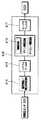
ここで、チャージアンプ(増幅手段)410の回路構成を図6に示す。チャージアンプ410は、少なくとも、圧電素子部320からの電荷を増幅して電圧に変換する電荷増幅/電圧変換回路414とこの電荷増幅/電圧変換回路414からの電圧を増幅する増幅回路415とを有する。本実施形態においては、チャージアンプ410は、さらに、両回路414、415の間に、例えば0.5Hzのハイパスフィルタ416を有し、増幅回路415の後段に、例えば5KHzのローパスフィルタ417を有する。
【0073】
なお、増幅回路415には、必要に応じて補正回路であるゲイン調整及びオフセット調整回路を設定しても良い。また、ハイパスフィルタ416、ローパスフィルタ417を独立とする替わりに、バンドパスフィルタに置き換えても良い。この場合、増幅回路415前に配置することが望ましい。
【0074】
この増幅回路415を有するチャージアンプ410においては、例えば燃焼制御を行なう際、燃焼圧センサ300の圧電素子部320からの電気信号を、ECU(外部回路)内へ直接入力可能な0〜3.5Vの作動電圧に増幅変換することが可能となっている。
【0075】
また、ハイパスフィルタ416の内蔵により、圧電セラミックス特有で温度変化によって発生する0.1Hz〜数十Hzの低周波パイロ電気出力(いわゆるベース電圧)のドリフト、さらにはローパスフィルタ417の内蔵により、例えばグロープラグの固有振動及びインジェクタ作動時のノズル着座振動といった数KHz〜数十KHzの高周波機械振動など、電気的及び機械的な振動ノイズの除去が可能となっている。
【0076】
また、メタルカバー420の大径口423及びメタルキャップ424は、例えば、PPS、ナイロン、PBT等よりなるキャップ状のコネクタ部425にて覆われている。このコネクタ部425は、図5(b)に示す様に、3本のチャージアンプ410の出力端子412の先端を露出するように支持し、ECUから延びる他の配線部材(図示せず)が接続可能な形状となっている。
【0077】
また、メタルカバー420には、ねじ穴を備えたステー(本発明でいう取付部)426が溶接等で接合されており、このステー426により、コネクタ400はエンジンルーム内の適所に搭載、固定されるようになっている。また、メタルカバー420の外周側面のうちコネクタ部425にて覆われる部位には、切欠き溝427が形成され、この切欠き溝427とコネクタ部425とが引っかかることにより、軸方向での引張り強度の補強とコネクタ部425の回転防止が為されるようになっている。
【0078】
かかるコネクタ400は、次のように形成される。まず、メタルカバー420内にてリード線500とチャージアンプ410とを結線し、且つメタルカバー420にメタルキャップ424を合致させる。この状態のものを、コネクタ部425を形成するための射出型に配置固定し、さらに、出力端子412とメタルキャップ424との接触防止及び位置固定を行うため、出力端子412は射出型の中子型にて保持・固定する。
【0079】
そして、例えば、PPS、ナイロン、PBT等の熱可塑性樹脂を射出型内に射出して射出成形することで、コネクタ部425が形成される。このとき、メタルキャップ424の端子通し穴424aから樹脂413がメタルカバー420内に充填され、チャージアンプ410のモールドが同時に行われる。このように、単一工程でメタルカバー420内への樹脂充填と出力端子412の保持・固定、及びコネクタ部425の形成を行うことができる。
【0080】
これにより、ICチップ化され、樹脂モールドされたチャージアンプ410は、信号取出線501を含め再び樹脂モールドされることとなり、防塵・防水効果は極めて向上する。また、チャージアンプ410は、アースされた金属製のメタルカバー420、メタルキャップ424、固定金具422等により全体を包含されており、耐電気ノイズ性も確保することができる。
【0081】
以上のように、本実施形態のグロープラグ100は、プラグ本体部200、燃焼圧センサ300、コネクタ400、及びリード線500を備えて構成されている。次に、上記グロープラグ100における燃焼圧の検出メカニズムについて、その全体を通して述べる。
【0082】
グロープラグ100におけるプラグ本体部200は、エンジンヘッド1に設けられているねじ穴(グローホール)に装着され、燃焼圧センサ300は、ハウジング201の取付けねじ201aを介し、圧電素子部320の圧電セラミックス321に対してプラグの軸方向へ荷重が負荷される様に、該プラグ本体部200へ装着されている。
【0083】
ディーゼルエンジンの始動時、図示されていない電源からコネクティングバー2を介してプラグ本体部200に電圧が印加され、中軸204、発熱コイル203、シース管202、ハウジング201を介してエンジンヘッド1にアースされる。これにより、発熱体206は発熱し、ディーゼルエンジンの着火始動補助を行うことができる。そして、エンジン始動後、エンジン内で発生した燃焼圧は、発熱体206、ハウジング201を介して取付けねじ201aに伝達される。
【0084】
続いて、取付けねじ201aに伝達された燃焼圧は、グロープラグ100におけるエンジンヘッド1への締付けトルクを緩和させる。それに伴い、燃焼圧センサ300におけるナット310のねじ部311を介して圧電セラミックス321に負荷されている荷重が緩和される(即ち、圧電セラミックス321に負荷されている荷重状態が変化する)ため、圧電セラミックス321の有する圧電特性に沿って出力される電気信号の発生電荷が変化する。
【0085】
尚、該信号は、信号取出側ワッシャリング322、電極331を介した信号取出線501と、またアースされているアース側ワッシャリング323、台座340、ハウジング201、取付けねじ201a、ねじ部311を介してアース側シールド線503との間に出力される。
【0086】
そして、該出力信号は、リード線500を介して結線されているコネクタ400のチャージアンプ410へ入力される。この入力された信号は、電荷増幅/電圧変換回路414、ハイパスフィルタ416、増幅回路415、ローパスフィルタ417にて順次、信号処理された後、チャージアンプ410の出力端子412からECUへ入力されることによって、電気信号として、例えば燃焼制御へ応用される。以上が、上記グロープラグ100における燃焼圧の検出メカニズムの全体である。
【0087】
ところで、本実施形態のようにチャージアンプ内蔵型コネクタを有するグロープラグによれば、コネクタ400に、圧電セラミックス321からの電気信号(燃焼圧センサ300の出力信号)を増幅するチャージアンプ(増幅手段)410が内蔵されている。そのため、チャージアンプ410をコネクタ400と共に、燃焼圧センサ300近傍であるエンジンルーム内(例えばエンジンヘッドやヘッドカバー等)に配置できる。
【0088】
これにより、燃焼圧センサ300の出力信号を該センサ300の近傍にて増幅でき、また、燃焼圧センサ300とチャージアンプ410とを結ぶリード線(配線部材)500も、従来に比べて最小限に短化(例えば、30cm以下)でき、リード線500の時つ静電浮遊容量を減少させ、出力信号の減衰を抑制できる。よって、本グロープラグ100によれば、センサ300の出力信号の減衰を抑制するとともに、該出力信号に対する電気的ノイズを低減することができる。
【0089】
また、本実施形態では、リード線500を、アースされたアース側シールド線(本発明でいう被覆部材)503にて電気的にシールドされており、さらに、このアース側シールド線503及びメタルカバー420等を介して、チャージアンプ410も電気的にシールドされたものとしている。そのため、圧電セラミックス321からの電気信号(燃焼圧センサ300の出力信号)に対してより電気的ノイズがのりにくいものとなっている。
【0090】
また、本実施形態によれば、チャージアンプ410を樹脂413でモールドしているため、コネクタ400の小型化かつチャージアンプ410とコネクタ400との一体化が図れ、チャージアンプ410における確実な防水、防塵構造が実現できる。そのため、塵・水・或るいは露結等による燃焼圧センサ300の出力信号のリークを防止でき、燃焼圧センサ300の出力信号の減衰をより高いレベルにて抑制することができる。
【0091】
また、本実施形態によれば、チャージアンプ410に、圧電セラミックス321からの電気信号中の電気的ノイズを除去するためのフィルタ回路として、ハイパスフィルタ416及びローパスフィルタ417を持たせたことを特徴としており、圧電セラミックス321からの電気信号(燃焼圧センサの出力信号)に対する電気的ノイズを効果的に除去することができる。
【0092】
そして、この結果、チャージアンプ410からのECUへの入力信号は、極めてS/N比に優れた燃焼圧信号とすることができる。また、圧電セラミックスを用いた燃焼圧センサ付きグロープラグ特有の上記ノイズ信号、即ち、上記した低周波パイロ電気出力のドリフト、グロープラグの固有振動及びインジェクタ作動時のノズル着座振動等の電気的及び機械的な振動ノイズの除去を、チャージアンプ410側で処理でき、ECUへの入力信号は一般的な汎用性が保たれるため、ECU側でのハード面の改造の負担を軽減できる。
【0093】
次に、本実施形態による効果について、図7〜図13を参照して、より具体的に述べていく。図7及び図8は共に、エンジン条件がアイドリング時の試験結果を表す波形図であり、図7は本実施形態の燃焼圧センサ付きグロープラグ100、図8はチャージアンプ410を車室内のECU近傍に搭載した従来の燃焼圧センサ付きグロープラグを示す。
【0094】
また、図7及び図8において、(a)は燃焼圧センサ付きグロープラグと指圧計との出力波形比較図、(b)は燃焼圧センサ付きグロープラグからの出力を縦軸に、指圧計からの出力を横軸にとった相関出力波形図を示している。ここで、指圧計は例えば燃焼室内に直に取り付けられた筒内センサを採用している。
【0095】
本実施形態のグロープラグ100の出力波形は、図7から判る様に、指圧計からの出力波形と略同一形状を示すと共に、相関出力波形も圧力上昇時及び減少時とも略同じ値を示し、かつ電気ノイズは検出されていない。一方、従来のものの出力波形は、図8に示す様に、その出力波高値H1が指圧計の出力波高値H2に比べ約20%減少しており、相関出力波形も楕円を示し、出力波形には時間的遅れも発生している。
【0096】
また、従来においては、特に燃焼による圧力上昇直前付近(α点)、すなわち電磁式インジェクタの燃料噴射時期には規則的な電気ノイズN1の発生が見られる。この電気ノイズN1は、上記α点を不明確なものとし、結果として、例えば燃焼制御に必要な燃焼に伴うシリンダ内の圧力上昇値・及び燃焼開始時期の検出可否や精度に大きく影響を及ぼす事となる。
【0097】
それに対して、本実施形態のグロープラグ100によれば、燃焼圧センサ300近傍での出力信号の増幅、リード線500の短化、及び、リード線500及びチャージアンプ410の電気的なシールド等により、出力信号の減衰の抑制及びインジェクタ作動時のノイズ低減が実現できており、このグロープラグ100からの燃焼圧信号を用いて精度の良い燃焼制御が可能となる。
【0098】
続いて、図9は、本実施形態と従来の燃焼圧センサ付きグロープラグとの比較において、ヘッドランプ、ハザードランプ等、全10評価項目の動作による主なリレー接点ノイズの影響状況を示す図表(エンジン条件はアイドリング)である。図9中、○は電気ノイズが観測されなかったことを示し、×は電気ノイズが観測されたことを示す。
【0099】
本実施形態では、ラジオ及びドアロックを除き、従来のものにおいて電気ノイズが観測されていた比較的、大電流を必要とする8項目に対しても、センサ300からの出力信号には、電気ノイズは観測されず、耐電気ノイズ性の有効性が確認されている。
【0100】
ここで、図10は、従来の燃焼圧センサ付きグロープラグにおいて発生するリレー接点ノイズの一例を示す波形図であり、(a)はヘッドランプON/OFF時、(b)はハザードランプ点滅時におけるセンサの出力信号への影響例を示している。ここで、リレー接点ノイズを問題として取り上げる理由であるが、これは、インジェクタ作動時の発生ノイズと異なり、偶発的に発生する点にある(つまり、予期できないノイズである)。
【0101】
図10(b)においては、ハザードランプ点滅時、燃焼に伴う圧力上昇のピーク値から離れたところに電気ノイズN3が発生しているが、図10(a)においては、ヘッドランプON/OFF時、偶然にも燃焼に伴う圧力上昇のピーク値付近に電気ノイズN2が発生している。
【0102】
このため、例えば燃焼制御において、ピークホールド回路を用いた圧力上昇のピーク値を演算すると、実際よりも発生ノイズを加算した値を算出する結果となり、例えばECUは、目標燃焼圧よりも値が著しく大きいと判断し燃料噴射量を減少させたり、またEGR量を増量して目標燃焼圧まで燃焼圧を下げようとする。
【0103】
その結果、エンジン出力が急激に低下したり、回転変動等のイレギュラーが生じ、ドライバーに対して衝撃やエンジン振動等の不快感を与えることとなる。こういった観点からも出力信号からの電気ノイズ除去によるS/N比向上は不可欠であり、本実施形態によれば、これらの不具合を防止できる。
【0104】
次に、図11は、本実施形態のローパスフィルタ417による機械的及び電気的ノイズ信号の除去効果を示す波形図である。この図11は、エンジン条件が2000rpmで全負荷時の試験結果を示すもので、(a)は、ローパスフィルタを介在しない従来の燃焼圧センサ付きグロープラグと指圧計との出力波形比較図、(b)は本実施形態であり、5KHzのローパスフィルタ417を介在した出力波形比較図を示している。この図から判る様に、ローパスフィルタ417の介在によって、連続的に発生しているエンジン周囲からの高周波機械振動ノイズは除去されている。
【0105】
次に、図12及び図13を用いて、ハイパスフィルタ416による機械的及び電気的ノイズ信号の除去効果を示す。図12は、ハイパスフィルタを介在しない従来の燃焼圧センサ付きグロープラグと指圧計との出力を連続的に64波形取り込んだ時の出力波形比較図であり、(a)はエンジン条件がアイドリングの場合、(b)はエンジン条件が1200rpmで40N・m負荷時の場合の、それぞれ試験結果を示している。
【0106】
圧電セラミックス特有のパイロ電気出力により、従来の燃焼圧センサ付きグロープラグにおける出力のべース電圧のドリフト幅は、両エンジン条件共に、指圧計に比べて大幅に上回っていることが判る。
【0107】
図13は、本実施形態にて介在するハイパスフィルタ416の設定周波数を変化させた場合(0.1Hz、0.5Hz)における指圧計とのドリフト幅を、燃焼圧ピーク比を用いて数値比較したものである。ここで言う燃焼圧ピーク比とは、連続的な燃焼圧出力64波形において最大ドリフト幅に対する燃焼圧ピーク値の割合を示しており、値が小さい程優れる事を意味している。
【0108】
例えば、図12(a)に示されるドリフト幅D、燃焼圧ピーク値Pを用い、ドリフト幅Dの最大値をDmaxとしたとき、燃焼圧ピーク比は、(Dmax/P)×100にて求められる。なお、図13においては、比較として従来の燃焼圧センサ付きグロープラグ、つまりハイパスフィルタの無いものの燃焼圧ピーク比も示してある。
【0109】
結果として、0.5Hzのハイパスフィルタ416の介在により、ドリフト幅は従来の1/4〜1/5まで低減され、図13から判る様に、燃焼圧ピーク比は指圧計と略同じ値を示している。このように、本実施形態では、ハイパスフィルタ416の介在によって、圧電セラミックス特有の低周波パイロ電気出力によるノイズが除去できる。
【0110】
(第2実施形態)
本第2実施形態は、上記第1実施形態と比較して、プラグ本体部200は同一構成であるが、リード線を廃止して、燃焼圧センサ自体と圧電セラミックス(圧電素子)321からの電気信号を増幅するチャージアンプ(増幅手段)410とを樹脂にてモールドし、一体化・内蔵させたところが異なる。
【0111】
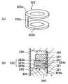
図14は、本実施形態の燃焼圧センサ付きグロープラグ100における燃焼圧センサ600の詳細拡大図であり、(a)は縦断面、(b)は(a)中のC矢視図を示す。なお、図中、上記第1実施形態と同一部分には同一符号を付し、説明を簡略化する。
【0112】
本実施形態の燃焼圧センサ600は、大きくは、センサ本体をプラグ本体部200に取り付けるためのセンサ固定部310と、燃焼圧に伴う力に応じて電気信号(電荷)を発生する圧電セラミックス321と、この圧電セラミックス321にて発生した電気信号を取出すための電極331と、センサ固定部310とともに圧電セラミックス321及び電極331を挟持するための台座340と、圧電セラミックス321の防塵、防水を図るためのメタルケース350と、電極331と接続されたチャージアンプ410を内蔵するコネクタ部610と、を備えている。
【0113】
本実施形態のセンサ固定部310は、プラグ本体部200のハウジング201に設けられた取付ねじ201aを介してセンサ本体を装着固定するための固定ナット318と、この固定ナット318とは別体であり且つ固定ナット318の軸力により圧電セラミックス321及び電極331を押さえつける部分としての押さえ部319とから構成されている。
【0114】
固定ナット318は、上記第1実施形態におけるナット310の六角部312と同一構成であり、押さえ部319は、上記ナット310の六角部312を除いた部分に相当し、大径部313及び小径部314を有する。ただし、上記第1実施形態とは異なり、固定ナット318及び押さえ部319においてリード線を導くための穴は形成されていない。
【0115】
また、押さえ部319の内周面には、ねじ部は形成されておらず、押さえ部319は、ハウジング201の軸回りに自由に回転可能となっている。また、押さえ部319の小径部314の外周面には、絶縁チューブ315が密着固定されている。
【0116】
環状の一対の圧電セラミックス321は、環状の電極331を挟んで積層構造を構成している。この積層体は、絶縁チューブ315で被覆された押さえ部319の小径部314の外縁に嵌入され、固定ナット318の軸力により、押さえ部319の大径部313と台座340との間に挟持されている。そして、チャージアンプ410の入力端子411が、メタルケース350に形成されたスリットもしくは穴を通して、電極331の外周側面に形成された穴に溶接され結線されている。
【0117】
コネクタ部610は、電極331と結線されたチャージアンプ410、メタルケース350及び台座340を包み込むように、樹脂611でモールドしてなる。コネクタ部610におけるチャージアンプ410の出力端子412側は、ECUから延びる他の配線部材(図示せず)が該出力端子412に接続可能な形状となっている。そして、コネクタ部610は、固定ナット318で締め付けを行っていない状態のとき、固定ナット318を除くセンサの他の部分と一体に、ハウジング201の軸回りに自由に回転可能となっている。
【0118】
かかる燃焼圧センサ600は、ハウジング201の取付けねじ201aを介し、圧電セラミックス321に対してプラグの軸方向へ荷重が負荷される様に、該プラグ本体部200へ装着されている。
【0119】
そして、取付けねじ201aに伝達された燃焼圧によって、燃焼圧センサ600における固定ナット318を介して圧電セラミックス321に負荷されている荷重が緩和されるため、圧電セラミックス321の有する圧電特性に沿って出力される電気信号の発生電荷が変化する。該出力信号は、電極331を介してチャージアンプ410へ入力され、信号処理された後、出力端子412からECUへ入力される。
【0120】
ところで、本実施形態のようにチャージアンプ内蔵型燃焼圧センサを有するグロープラグによれば、チャージアンプ410が燃焼圧センサ600自身に内蔵されているため、燃焼圧センサ600の出力信号を該センサ内にて増幅することにより、該センサの出力信号の減衰を抑制できる。
【0121】
また、本実施形態によれば、該センサとチャージアンプ410との間をつなぐリード線の廃止により出力感度への減衰要因が排除され、ライン並走ノイズへの影響も低減でき、該出力信号に対する電気的ノイズを低減することができる。ただし、チャージアンプ410の入力端子411は、単に樹脂611でモールドされている状態即ち電気ノイズに対し一部露出した状態となっているため、完全にシールドされた上記第1実施形態に比べて、総合的には耐電気ノイズ性はやや劣る可能性がある。
【0122】
また、本実施形態の燃焼圧センサ600は、燃焼圧センサの取付けスペースに余裕がある場合、特に有効であるが、より適用範囲を広げるため、固定ナット318で締め付けを行っていない状態のとき、ハウジング201の軸回りに自由に回転可能な構成となっている。
【0123】
上記の回転可能な構成を採用することによって、装着時にはセンサ600に取付けの方向性を持たせ、かつ、突出したコネクタ部610を回転させること無く固定ナット318の回転のみで装着できるため、回転による装着に伴う必要空間の削減を図ることができる。
【0124】
また、本実施形態によれば、押さえ部319、圧電セラミックス321、電極331、台座340及びメタルケース350からなるセンサ部分と、チャージアンプ410を内蔵するとコネクタ部610とを、樹脂611による射出成形にて一体化することで、チャージアンプ410における、確実な防水、防塵構造が同時に実現できる。
【0125】
その結果、塵・水・或いは露結等による燃焼圧センサ600の出力信号のリークを防止でき、燃焼圧センサ600の出力信号の減衰をより高いレベルにて抑制できる。さらに、第1実施形態と比較すれば、総部品点数と作業工程は半減でき、低コストで簡素な構造の燃焼圧センサを提供できる。
【0126】
また、本実施形態によれば、上記第1実施形態にあったようなリード線で結線されたチャージアンプ内蔵型コネクタの廃止により、装着に伴うリード線の断線及び衝撃打痕によるチャージアンプの破損がなくなり、また一方では、固定ナット318による装着を行うようにしており、インパクトレンチの使用が可能となるため、信頼性、装着作業性が共に一段と向上する。
【0127】
(他の実施形態)
なお、上記第1実施形態において、エンジンルーム内に取付可能なステー(取付部)426を有するチャージアンプ410をリード線500の途中部に介在設定しても良い。この場合も、チャージアンプ410をエンジンルーム内に配置でき、燃焼圧センサ300の出力信号を該センサの近傍にて増幅できるため、燃焼圧センサの出力信号の減衰を抑制するとともに、該出力信号に対する電気的ノイズを低減することができる。ただし、この場合、図15に示す様に、チャージアンプ410の後段のリード線500は、チャージアンプ410の3本の出力端子412に接続するため3本必要であり、これら3本のリード線の結線が複雑となる。
【0128】
また、チャージアンプはICチップ化されたものでなくとも良く、上記各実施形態に適用可能な形状、大きさを有する一般的な回路基板として構成されたものであっても良い。また、チャージアンプ(増幅手段)410の回路構成は図16に示す様なものであっても良い。図16においては、上記図6に示す電荷増幅/電圧変換回路414を、出力を微分及び積分する出力微分/積分回路414aと、出力微分/積分回路414aからの電流を電圧に変換する電流/電圧変換回路414bとに置き換えたものである。
【0129】
また、上記実施形態では、リード線500の他端側に設けられたコネクタ400のメタルカバー420、あるいは、リード線500の途中部に介在設定されたチャージアンプ(増幅手段)410に、ステー(取付部)426を設け、これらコネクタ及び増幅手段をエンジンルーム内に容易に取り付け可能としたが、これらステー426は無くても良い。その場合には、これらコネクタ400やチャージアンプをエンジンルーム内の適所に接着したり、別体のブラケット等にて固定すれば良い。
【0130】
なお、上記実施形態では、燃焼圧センサ構造体として、燃焼圧センサ付きグロープラグを例にとって説明したが、本発明は、燃焼圧センサ付きグロープラグのみならず、エンジンルーム内に配設されたエンジンに取り付られる構造体(例えばインジェクタ、ボルト、スパークプラグ等)と、該構造体に取り付けられてエンジンの燃焼圧を検出する燃焼圧センサと、を備える燃焼圧センサ構造体に適用可能である。
【0131】
スパークプラグ700への適用例を図17に、インジェクタ800への適用例を図18に、ボルト900への適用例を図19に、それぞれ示す。図17においては、スパークプラグ(本発明でいう構造体)700は、ハウジング701に形成された取付ねじ701aによってガソリンエンジンのエンジンヘッド1に取り付けられている。
【0132】
図18においては、ガソリンまたはディーゼルエンジンのエンジンヘッド1に対して、燃料ポンプからの燃料を燃焼室1a内に噴射するインジェクタ(本発明でいう構造体)800が、固定ボルト801及び取付ねじ801aにより取り付けられている。また、図19においては、エンジンヘッド1内の燃焼室1aに露出した部材としてのボルト(本発明でいう構造体)900がエンジンヘッド1に取り付けられている。
【0133】
そして、図17〜図19において、燃焼圧センサ(圧力センサ)300は、各々の構造体700〜900における取付ねじ701a、801a、901aに対して取り付けられており、これら構造体に作用する燃焼圧に伴う力を圧電素子321の圧電特性に基づく電気信号に変換することによりエンジンの燃焼圧を検出するようになっている。
【0134】
これら図17〜図19に示す例においても、燃焼圧センサ300、コネクタ400及びリード線500は、上記第1実施形態と同様の構成であり、その効果も同様である。また、これら図17〜図19に示す例においても、上記第2実施形態及び、図15及び図16に示す変形例を適用できることは勿論である。
【図面の簡単な説明】
【図1】本発明の第1実施形態に係る燃焼圧センサ付きグロープラグの全体概略断面図である。
【図2】図1中の燃焼圧センサを拡大して示す詳細説明図である。
【図3】図2中の圧電素子部の詳細説明図である。
【図4】図2中の圧電素子部における電極面の方向性を示す図である。
【図5】図1中のコネクタを拡大して示す詳細説明図である。
【図6】本発明に係る増幅手段(チャージアンプ)の回路構成図である。
【図7】第1実施形態における燃料噴射時に伴うノイズの除去効果を示す波形図である。
【図8】従来における燃料噴射時に伴うノイズの影響を示す波形図である。
【図9】第1実施形態におけるリレー接点ノイズの除去効果を示す図表である。
【図10】従来におけるリレー接点ノイズの一例を示す波形図である。
【図11】第1実施形態におけるローパスフィルタによるノイズの除去効果を示す波形図である。
【図12】従来におけるハイパスフィルタを介在しない場合のノイズの影響を示す波形図である。
【図13】第1実施形態におけるハイパスフィルタによるノイズの除去効果を示す図である。
【図14】本発明の第2実施形態にかかる燃焼圧センサ付きグロープラグにおける燃焼圧センサの詳細説明図である。
【図15】本発明におけるチャージアンプをリード線の途中部に介在設定した例を示す図である。
【図16】本発明に係る増幅手段(チャージアンプ)の他の回路構成例を示す図である。
【図17】本発明を構造体としてのスパークプラグに適用した例を示す図である。
【図18】本発明を構造体としてのインジェクタに適用した例を示す図である。
【図19】本発明を構造体としてのボルトに適用した例を示す図である。
【符号の説明】
1…エンジンヘッド、200…プラグ本体部、
300、600…燃焼圧センサ、321…圧電セラミックス、
400、400a…コネクタ、410…チャージアンプ、
413、611…樹脂、416…ハイパスフィルタ、
417…ローパスフィルタ、426…ステー、500…リード線、
503…アース側シールド線。[0001]
BACKGROUND OF THE INVENTION
The present invention provides a structure (for example, a glow plug, a spark plug, an injector, a bolt, etc.) attached to an engine disposed in an engine room, and a combustion pressure of the engine attached to the structure. And a combustion pressure sensor structure.
[0002]
[Prior art]
As this type of combustion pressure sensor structure, for example, a glow plug with a combustion pressure sensor, which is used as a starting assist device in an engine such as a diesel engine as described in Japanese Patent Laid-Open No. 7-139736, has been proposed. Yes. This is a plug body (glow heater) as a structure having a heating element that is attached to a diesel engine of a vehicle and generates heat when energized, and a piezoelectric ceramic (piezoelectric) that generates a force associated with the combustion pressure acting on the plug body. And a combustion pressure sensor (pressure sensor) that converts it into an electrical signal based on the piezoelectric characteristics of the element.
[0003]
In such a configuration, the combustion pressure generated in the engine is detected as a displacement of the plug body portion attached to the engine, and this displacement is applied to the piezoelectric ceramic of the combustion pressure sensor by a clamping force. It is transmitted as a change in shaft load, converted into an electrical signal, and output as a combustion pressure. The output signal (combustion pressure) is input to an external circuit (such as an ECU of the vehicle) disposed outside the engine room via a wiring member extending from the sensor, and is used for various controls of the engine.
[0004]
[Problems to be solved by the invention]
However, in general, since the impedance of piezoelectric ceramics is extremely high, such as several hundred KΩ to several tens MΩ, the charge generated from the piezoelectric ceramics in the combustion pressure sensor is transferred to the case and other wiring due to dust, water, or condensation. Easily leaks. Therefore, the output signal from the combustion pressure sensor is significantly divided on the way to the external circuit, and as a result, the output signal is attenuated.
[0005]
In addition, since the output signal of a combustion pressure sensor is extremely weak due to the characteristics of piezoelectric ceramics, it is necessary to suppress the attenuation of the output signal to the maximum, and an input signal (combustion pressure sensor) leading to an external circuit is required. The electrical noise resistance must be taken into consideration for the output signal from
[0006]
Here, conventionally, an amplifying means is provided in the vicinity of an external circuit provided outside the engine room, and an output signal from the sensor is amplified by the amplifying means, and a wiring member extending from the sensor to the amplifying means is long. Since it becomes a thing (for example, 1m-2m), it is easy to carry an electrical noise in the weak output signal of this sensor.
[0007]
By the way, from the viewpoint of electric noise resistance, computerization has recently progressed in diesel engines, and injectors that control fuel injection are no exception, and electromagnetization has been rapidly introduced. As a result, for example, in an injector close to the combustion pressure sensor, a current of dozens of amperes flows, wire parallel noise accompanying the current change during operation, or relay contact noise generated from a headlamp or hazard lamp, There are many sources of electrical noise, such as external induced noise, and it goes without saying that there is a need for electrical noise countermeasures for sensor output signals.
[0008]
Such a problem is not only a glow plug with a combustion pressure sensor, but also a structure (for example, a spark plug, an injector, a bolt, etc.) attached to the engine disposed in the engine room, and a structure attached to the structure. The combustion pressure sensor structure including the combustion pressure sensor that converts the combustion pressure of the engine into an electric signal is considered to occur as a common problem.
[0009]
Accordingly, in view of the above problems, the present invention provides a combustion pressure sensor structure including a structure attached to an engine and a combustion pressure sensor attached to the structure and converting the combustion pressure of the engine into an electric signal. An object of the present invention is to suppress the attenuation of the output signal of the pressure sensor and reduce electrical noise with respect to the output signal.
[0012]
[Means for Solving the Problems]
The present inventors have focused on amplifying the output signal of the combustion pressure sensor in the vicinity of the sensor, and have come to create means for solving the above-mentioned object. That is,Claim1In this invention, the combustion pressure sensor (600) and the amplifying means (410) for amplifying the electric signal from the piezoelectric element (321) are molded with resin, and integrated and built-in.And
The combustion pressure sensor (600) has a sensor fixing part (310),
The sensor fixing portion (310) includes a fixing nut (318) that is screw-coupled to a mounting screw (201a) of the structure (200, 700, 800, 900), and a presser that is separate from the fixing nut (318). Part (319),
The piezoelectric element (321) and the amplifying means (410) are integrated on the pressing portion (319) side of the sensor fixing portion (310),
In a state where the fixing nut (318) is not tightened, the pressing portion (319) can freely rotate around the axis of the mounting screw (201a) of the structure together with the piezoelectric element (321) and the amplifying means (410). And
The combustion pressure sensor (600) is attached to the structure by the axial force of the fixing nut (318) by rotating the fixing nut (318) and screwing the fixing nut (318) to the mounting screw (201a).It is characterized by that.
[0013]
As a result, the amplifying means is built in the combustion pressure sensor itself, so that the output signal of the combustion pressure sensor is amplified in the sensor, so that attenuation of the output signal of the sensor can be suppressed and the sensor and the amplification are amplified. Since a wiring member connecting between the means and the means can be eliminated, electrical noise with respect to the output signal can be reduced.
In addition, since the combustion pressure sensor (600) can be attached only by rotating the fixing nut (318), the necessary space accompanying sensor mounting due to the rotation of the fixing nut (318) can be reduced.
[0016]
Also, ContractClaim2In the invention of the aboveClaim 1The amplifying means (410) in the invention is characterized by being electrically shielded.According to this,Electrical noise can be made more difficult to be applied to the electrical signal from the piezoelectric element (the output signal of the combustion pressure sensor).
[0018]
Claims3In the invention ofIn the invention of
[0020]
In addition, the code | symbol in the bracket | parenthesis of each said means is an example which shows a corresponding relationship with the specific means as described in embodiment mentioned later.
[0021]
DETAILED DESCRIPTION OF THE INVENTION
(First embodiment)
In the present embodiment, the combustion pressure sensor structure of the present invention is described as being embodied in a glow plug with a combustion pressure sensor. FIG. 1 is a partial longitudinal sectional view showing a general outline of a
[0022]
The
[0023]
The
[0024]
The plug main body (structure) 200 includes a hollow pipe-
[0025]
One end of the
[0026]
The
[0027]
Here, in a portion including the
[0028]
In addition, inside the upper end side of the
[0029]
The
[0030]
The connecting
[0031]
In addition to the so-called metal heating element based on the metal resistance wire described above, the
[0032]
Next, the entire
[0033]
The
[0034]
First, the
[0035]
The
[0036]
The
[0037]
Here, the
[0038]
Then, on one end side of the
[0039]
The fixing fitting 333 is for fixing the
[0040]
The fixing
[0041]
Next, the
[0042]
As shown in FIG. 3B, the
[0043]
In addition, as shown in FIG. 3A, the signal extraction
[0044]
In addition, the ground
[0045]
In the
[0046]
Next, the
[0047]
Further, a metal
[0048]
In the
[0049]
Further, the
[0050]
Thus, the
[0051]
The method for assembling the
[0052]
An
[0053]
Thereafter, a part of the
[0054]
Next, the
[0055]
Thus, the
[0056]
The
[0057]
The first feature is that, as shown in FIG. 4, the orientation of the electrode surface of the piezoelectric ceramic 321 that is polarized positively and negatively when the constituent elements are arranged in a stacked manner in the
[0058]
The second feature is that the
[0059]
As a result, first, the laser welded portion of the
[0060]
Further, since the
[0061]
The third feature is that in the
[0062]
The fourth feature is that the piezoelectric ceramic 321 that is a signal generation source and the
[0063]
The fifth feature is that in the small space between the
[0064]
The sixth feature is that when the
[0065]
Next, the
[0066]
A metal-made hollow pipe-shaped fixing fitting 422 is fitted into the small-
[0067]
On the other hand, a
[0068]
The other end of the
[0069]
On the other end side of the
[0070]
The
[0071]
In addition, the
[0072]
Here, the circuit configuration of the charge amplifier (amplifying means) 410 is shown in FIG. The
[0073]
Note that a gain adjustment and offset adjustment circuit, which is a correction circuit, may be set in the
[0074]
In the
[0075]
Further, the built-in high-
[0076]
The large-
[0077]
In addition, a stay (attachment portion in the present invention) 426 having a screw hole is joined to the
[0078]
The
[0079]
For example, a
[0080]
As a result, the
[0081]
As described above, the
[0082]
The
[0083]
When starting the diesel engine, a voltage is applied to the
[0084]
Subsequently, the combustion pressure transmitted to the mounting
[0085]
The signal is sent via a signal extraction
[0086]
The output signal is input to the
[0087]
By the way, according to the glow plug having the charge amplifier built-in type connector as in this embodiment, the charge amplifier (amplifying means) for amplifying the electrical signal (output signal of the combustion pressure sensor 300) from the piezoelectric ceramic 321 to the
[0088]
As a result, the output signal of the
[0089]
In the present embodiment, the
[0090]
Further, according to the present embodiment, since the
[0091]
Further, according to the present embodiment, the
[0092]
As a result, the input signal from the
[0093]
Next, the effect of this embodiment will be described more specifically with reference to FIGS. 7 and 8 are waveform diagrams showing the test results when the engine condition is idling. FIG. 7 is a
[0094]
7 and 8, (a) is an output waveform comparison diagram of a glow plug with a combustion pressure sensor and a finger pressure gauge, and (b) is an output from the glow plug with a combustion pressure sensor on the vertical axis, The correlation output waveform figure which took this output on the horizontal axis is shown. Here, the tonometer employs, for example, an in-cylinder sensor mounted directly in the combustion chamber.
[0095]
As can be seen from FIG. 7, the output waveform of the
[0096]
Conventionally, regular electrical noise N1 is generated particularly near the point immediately before the pressure increase due to combustion (α point), that is, at the fuel injection timing of the electromagnetic injector. This electrical noise N1 makes the α point unclear, and as a result, for example, the pressure rise value in the cylinder accompanying combustion necessary for combustion control, and whether or not it is possible to detect the combustion start timing and the accuracy are greatly affected. It becomes.
[0097]
On the other hand, according to the
[0098]
Next, FIG. 9 is a chart showing the influence status of main relay contact noise due to the operation of all 10 evaluation items such as a headlamp and a hazard lamp in comparison between the present embodiment and a conventional glow plug with a combustion pressure sensor. The engine condition is idling. In FIG. 9, ◯ indicates that no electrical noise was observed, and x indicates that electrical noise was observed.
[0099]
In the present embodiment, except for radio and door locks, electrical noise is observed in the output signal from the
[0100]
Here, FIG. 10 is a waveform diagram showing an example of relay contact noise generated in a conventional glow plug with a combustion pressure sensor, (a) when the headlamp is ON / OFF, and (b) when the hazard lamp blinks. An example of the influence on the output signal of the sensor is shown. Here, the reason why the relay contact noise is taken up as a problem is that it is an accidental occurrence (that is, an unexpected noise) unlike the noise generated when the injector is operated.
[0101]
In FIG. 10 (b), when the hazard lamp blinks, the electric noise N3 is generated at a position away from the peak value of the pressure increase due to combustion. In FIG. 10 (a), the head lamp is turned on / off. The electric noise N2 is generated near the peak value of the pressure increase due to combustion.
[0102]
For this reason, for example, in the combustion control, when the peak value of the pressure increase using the peak hold circuit is calculated, a result of adding the generated noise to the actual value is calculated. For example, the ECU has a value significantly higher than the target combustion pressure. It is determined that the fuel injection amount is large, and the fuel injection amount is decreased, or the EGR amount is increased to decrease the combustion pressure to the target combustion pressure.
[0103]
As a result, the engine output rapidly decreases, irregularities such as rotational fluctuations occur, and the driver is given an uncomfortable feeling such as impact and engine vibration. From this point of view, it is indispensable to improve the S / N ratio by removing electrical noise from the output signal. According to this embodiment, these problems can be prevented.
[0104]
Next, FIG. 11 is a waveform diagram showing the effect of removing mechanical and electrical noise signals by the low-
[0105]
Next, the effect of removing mechanical and electrical noise signals by the high-
[0106]
From the pyroelectric output unique to piezoelectric ceramics, it can be seen that the drift width of the output base voltage in the conventional glow plug with a combustion pressure sensor is significantly greater than that of the finger pressure gauge in both engine conditions.
[0107]
FIG. 13 is a numerical comparison of the drift width with a chimometer when the set frequency of the high-
[0108]
For example, when the drift width D and the combustion pressure peak value P shown in FIG. 12A are used and the maximum value of the drift width D is Dmax, the combustion pressure peak ratio is obtained by (Dmax / P) × 100. It is done. In FIG. 13, for comparison, the combustion pressure peak ratio of a conventional glow plug with a combustion pressure sensor, that is, a high-pass filter is also shown.
[0109]
As a result, the drift width is reduced to ¼ to 5 of the conventional one by the intervention of the high-
[0110]
(Second Embodiment)
Compared with the first embodiment, the second embodiment has the same configuration as that of the plug
[0111]
FIG. 14 is a detailed enlarged view of the
[0112]
The
[0113]
The
[0114]
The fixing
[0115]
In addition, no screw portion is formed on the inner peripheral surface of the
[0116]
The pair of annular
[0117]
The
[0118]
The
[0119]
Since the load applied to the piezoelectric ceramic 321 via the fixing
[0120]
By the way, according to the glow plug having the charge amplifier built-in type combustion pressure sensor as in the present embodiment, the
[0121]
In addition, according to the present embodiment, the elimination of the lead wire connecting the sensor and the
[0122]
Further, the
[0123]
By adopting the above-described rotatable configuration, the
[0124]
In addition, according to the present embodiment, the sensor portion including the
[0125]
As a result, leakage of the output signal of the
[0126]
Moreover, according to this embodiment, the charge amplifier built-in connector connected with the lead wire as in the first embodiment is abolished, and the charge amplifier is damaged due to the disconnection of the lead wire and the impact dent due to the mounting. On the other hand, the mounting with the fixing
[0127]
(Other embodiments)
In the first embodiment, the
[0128]
Further, the charge amplifier does not have to be an IC chip, and may be configured as a general circuit board having a shape and size applicable to each of the above embodiments. Further, the circuit configuration of the charge amplifier (amplifying means) 410 may be as shown in FIG. In FIG. 16, the charge amplification /
[0129]
In the above embodiment, the stay (attachment) is attached to the
[0130]
In the above embodiment, a glow plug with a combustion pressure sensor has been described as an example of the combustion pressure sensor structure. However, the present invention is not limited to a glow plug with a combustion pressure sensor, but an engine disposed in an engine room. It can be applied to a combustion pressure sensor structure including a structure (for example, an injector, a bolt, a spark plug, etc.) attached to the structure and a combustion pressure sensor attached to the structure and detecting the combustion pressure of the engine.
[0131]
An application example to the
[0132]
In FIG. 18, an injector (structure referred to in the present invention) 800 that injects fuel from a fuel pump into a
[0133]
17 to 19, the combustion pressure sensor (pressure sensor) 300 is attached to the mounting
[0134]
Also in the examples shown in FIGS. 17 to 19, the
[Brief description of the drawings]
FIG. 1 is an overall schematic cross-sectional view of a glow plug with a combustion pressure sensor according to a first embodiment of the present invention.
FIG. 2 is a detailed explanatory view showing an enlarged combustion pressure sensor in FIG. 1;
FIG. 3 is a detailed explanatory view of a piezoelectric element portion in FIG. 2;
4 is a diagram showing the directivity of the electrode surface in the piezoelectric element portion in FIG. 2. FIG.
FIG. 5 is a detailed explanatory view showing an enlarged connector in FIG. 1;
FIG. 6 is a circuit configuration diagram of amplification means (charge amplifier) according to the present invention.
FIG. 7 is a waveform diagram showing an effect of removing noise accompanying fuel injection in the first embodiment.
FIG. 8 is a waveform diagram showing the influence of noise associated with conventional fuel injection.
FIG. 9 is a chart showing an effect of removing relay contact noise in the first embodiment.
FIG. 10 is a waveform diagram showing an example of conventional relay contact noise.
FIG. 11 is a waveform diagram showing a noise removal effect by the low-pass filter in the first embodiment.
FIG. 12 is a waveform diagram showing the influence of noise when no conventional high-pass filter is interposed.
FIG. 13 is a diagram showing the noise removal effect by the high-pass filter in the first embodiment.
FIG. 14 is a detailed explanatory diagram of a combustion pressure sensor in a glow plug with a combustion pressure sensor according to a second embodiment of the present invention.
FIG. 15 is a diagram showing an example in which a charge amplifier according to the present invention is interposed in the middle of a lead wire.
FIG. 16 is a diagram showing another circuit configuration example of the amplifying means (charge amplifier) according to the present invention.
FIG. 17 is a diagram showing an example in which the present invention is applied to a spark plug as a structure.
FIG. 18 is a diagram showing an example in which the present invention is applied to an injector as a structure.
FIG. 19 is a diagram showing an example in which the present invention is applied to a bolt as a structure.
[Explanation of symbols]
1 ... engine head, 200 ... plug body,
300, 600 ... combustion pressure sensor, 321 ... piezoelectric ceramic,
400, 400a ... connector, 410 ... charge amplifier,
413, 611 ... resin, 416 ... high pass filter,
417 ... Low pass filter, 426 ... Stay, 500 ... Lead wire,
503: Earth side shielded wire.
Claims (3)
Translated fromJapanese前記構造体に取り付けられ、前記構造体に作用する前記エンジンの燃焼圧に伴う力を圧電素子(321)の圧電特性に基づく電気信号に変換する燃焼圧センサ(600)と、を備える燃焼圧センサ構造体において、
前記燃焼圧センサ(600)は、前記圧電素子(321)からの電気信号を増幅する増幅手段(410)と樹脂にてモールドし、一体化・内蔵したものであり、
前記燃焼圧センサ(600)はセンサ固定部(310)を有し、
前記センサ固定部(310)は、前記構造体の取り付けねじ(201a)にねじ結合される固定ナット(318)と、前記固定ナット(318)と別体になっている押さえ部(319)とから構成され、
前記圧電素子(321)及び前記増幅手段(410)は、前記センサ固定部(310)のうち前記押さえ部(319)側に一体化されており、
前記固定ナット(318)の締め付けを行っていない状態では、前記押さえ部(319)が前記圧電素子(321)及び前記増幅手段(410)とともに前記構造体の取り付けねじ(201a)の軸回りに自由に回転可能な構成となっており、
前記固定ナット(318)を回転させて前記取り付けねじ(201a)にねじ結合することで、前記固定ナット(318)の軸力により前記燃焼圧センサ(600)を前記構造体に取り付けることを特徴とする燃焼圧センサ構造体。A structure (200, 700, 800, 900) attached to the engine (1);
A combustion pressure sensor (600) attached to the structure and converting a force accompanying the combustion pressure of the engine acting on the structure into an electric signal based on a piezoelectric characteristic of the piezoelectric element (321). In the structure,
The combustion pressure sensor(600), said molded by amplifying means (410) and the resin for amplifying the electric signal from the piezoelectric element(321)state, and are not integrated,internal,
The combustion pressure sensor (600) has a sensor fixing part (310),
The sensor fixing portion (310) includes a fixing nut (318) screwed to the mounting screw (201a) of the structure, and a pressing portion (319) separate from the fixing nut (318). Configured,
The piezoelectric element (321) and the amplification means (410) are integrated on the pressing portion (319) side of the sensor fixing portion (310),
In a state where the fixing nut (318) is not tightened, the pressing portion (319) can freely move around the axis of the mounting screw (201a) of the structure together with the piezoelectric element (321) and the amplifying means (410). It can be rotated to
The combustion pressure sensor (600) is attached to thestructure by the axial force of the fixing nut (318) by rotating the fixing nut (318) and screwing the fixing nut (318a) to the mounting screw (201a). Combustion pressure sensor structure.
Priority Applications (1)
| Application Number | Priority Date | Filing Date | Title |
|---|---|---|---|
| JP2000358188AJP4407044B2 (en) | 1999-12-24 | 2000-11-24 | Combustion pressure sensor structure |
Applications Claiming Priority (3)
| Application Number | Priority Date | Filing Date | Title |
|---|---|---|---|
| JP36646599 | 1999-12-24 | ||
| JP11-366465 | 1999-12-24 | ||
| JP2000358188AJP4407044B2 (en) | 1999-12-24 | 2000-11-24 | Combustion pressure sensor structure |
Publications (2)
| Publication Number | Publication Date |
|---|---|
| JP2001241372A JP2001241372A (en) | 2001-09-07 |
| JP4407044B2true JP4407044B2 (en) | 2010-02-03 |
Family
ID=26581799
Family Applications (1)
| Application Number | Title | Priority Date | Filing Date |
|---|---|---|---|
| JP2000358188AExpired - Fee RelatedJP4407044B2 (en) | 1999-12-24 | 2000-11-24 | Combustion pressure sensor structure |
Country Status (1)
| Country | Link |
|---|---|
| JP (1) | JP4407044B2 (en) |
Cited By (4)
| Publication number | Priority date | Publication date | Assignee | Title |
|---|---|---|---|---|
| WO2014034641A1 (en)* | 2012-08-30 | 2014-03-06 | シチズンファインテックミヨタ株式会社 | Pressure detection device |
| JP2017506748A (en)* | 2014-02-25 | 2017-03-09 | キストラー ホールディング アクチエンゲゼルシャフト | Glow plug adapter |
| US10221782B2 (en) | 2014-04-04 | 2019-03-05 | Honda Motor Co., Ltd. | In-cylinder pressure detecting apparatus |
| WO2020105074A1 (en)* | 2018-11-19 | 2020-05-28 | 株式会社ミクニ | Pressure detection signal processing device, engine control system, and program |
Families Citing this family (14)
| Publication number | Priority date | Publication date | Assignee | Title |
|---|---|---|---|---|
| JP4593465B2 (en) | 2003-02-14 | 2010-12-08 | 本田技研工業株式会社 | Scooter type motorcycle with IC tag |
| DE102004011097A1 (en)* | 2004-03-06 | 2005-09-22 | Robert Bosch Gmbh | Device for detecting the combustion chamber pressure in an internal combustion engine |
| DE102004043874A1 (en)* | 2004-09-10 | 2006-03-16 | Robert Bosch Gmbh | Device for detecting the pressure in a combustion chamber of an internal combustion engine |
| JP4903165B2 (en)* | 2005-02-24 | 2012-03-28 | キストラー ホールディング アクチエンゲゼルシャフト | Piezoelectric force sensor parts or piezoelectric pressure sensor parts held by an electrical insulating film |
| JP4659675B2 (en)* | 2006-05-19 | 2011-03-30 | 日本特殊陶業株式会社 | Combustion pressure detector |
| JP5006696B2 (en)* | 2007-05-21 | 2012-08-22 | シチズンファインテックミヨタ株式会社 | Transmission cable for combustion pressure sensor |
| JP2012159231A (en)* | 2011-01-31 | 2012-08-23 | Iwate Industrial Research Center | Glow plug |
| JP5854638B2 (en)* | 2011-05-19 | 2016-02-09 | 株式会社ミクニ | Glow plug |
| JP5213195B2 (en)* | 2012-02-13 | 2013-06-19 | シチズンファインテックミヨタ株式会社 | Transmission cable for combustion pressure sensor |
| DE102013211389A1 (en)* | 2013-06-18 | 2014-12-18 | Robert Bosch Gmbh | sensor arrangement |
| JP6279925B2 (en)* | 2014-02-14 | 2018-02-14 | 日本特殊陶業株式会社 | Glow plug |
| KR101838002B1 (en)* | 2016-08-09 | 2018-03-13 | 주식회사 한국마스터 | Crimping machine sensor signal value method |
| KR101838004B1 (en)* | 2016-08-09 | 2018-03-13 | 주식회사 한국마스터 | Footswitch control methods crimping improve work safety and work efficiency of machine error detection |
| KR101827785B1 (en)* | 2016-08-09 | 2018-02-09 | 주식회사 한국마스터 | Alignment of the measurement signal and the reference signal by the crimping machine of the sort algorithm |
- 2000
- 2000-11-24JPJP2000358188Apatent/JP4407044B2/ennot_activeExpired - Fee Related
Cited By (6)
| Publication number | Priority date | Publication date | Assignee | Title |
|---|---|---|---|---|
| WO2014034641A1 (en)* | 2012-08-30 | 2014-03-06 | シチズンファインテックミヨタ株式会社 | Pressure detection device |
| JPWO2014034641A1 (en)* | 2012-08-30 | 2016-08-08 | シチズンファインデバイス株式会社 | Pressure detection device |
| JP2017506748A (en)* | 2014-02-25 | 2017-03-09 | キストラー ホールディング アクチエンゲゼルシャフト | Glow plug adapter |
| US10221782B2 (en) | 2014-04-04 | 2019-03-05 | Honda Motor Co., Ltd. | In-cylinder pressure detecting apparatus |
| WO2020105074A1 (en)* | 2018-11-19 | 2020-05-28 | 株式会社ミクニ | Pressure detection signal processing device, engine control system, and program |
| JPWO2020105074A1 (en)* | 2018-11-19 | 2021-12-02 | 株式会社ミクニ | Pressure detection signal processor, engine control system, and program |
Also Published As
| Publication number | Publication date |
|---|---|
| JP2001241372A (en) | 2001-09-07 |
Similar Documents
| Publication | Publication Date | Title |
|---|---|---|
| JP4407044B2 (en) | Combustion pressure sensor structure | |
| JP4300663B2 (en) | Combustion pressure sensor structure | |
| US6539787B1 (en) | Glow plug having a combustion pressure sensor | |
| JP4003363B2 (en) | Combustion pressure sensor structure | |
| JP3885515B2 (en) | Glow plug with combustion pressure sensor | |
| JP3942176B2 (en) | Glow plug with combustion pressure detection function and manufacturing method thereof | |
| US6973820B2 (en) | Combustion pressure sensor designed to ensure stability of output characteristic and sensitivity | |
| US7201043B2 (en) | Combustion pressure sensor and glow plug including the same | |
| JP2009527748A (en) | Pressure measuring device | |
| JP2004278934A (en) | Glow plug with combustion pressure detection function | |
| JP3912352B2 (en) | Glow plug with combustion pressure sensor | |
| JP3900059B2 (en) | Mounting structure and mounting method of glow plug with combustion sensor and glow plug with combustion pressure sensor | |
| JP2004124911A (en) | Glow plug with combustion pressure sensor | |
| EP1111360B1 (en) | Combustion pressure sensor device | |
| JP2010506179A (en) | Pressure measuring device | |
| EP1096140B1 (en) | Attachment structure of glow plug | |
| JP4207070B2 (en) | Glow plug with combustion sensor | |
| CN102713550A (en) | Ignition and pressure measuring devices for internal combustion engines | |
| JP2006284396A (en) | Combustion pressure sensor and glow plug equipped with it | |
| JP2006284011A (en) | Glow plug with combustion pressure sensor | |
| JPH07113714A (en) | Piezoelectric pressure sensor | |
| JP2004084619A (en) | Non-resonant knocking sensor | |
| JP2023049395A (en) | Pressure sensing device | |
| JP2018159283A (en) | Fuel injection valve with in-cylinder pressure sensor | |
| KR20070017279A (en) | Pressure sensor, manufacturing method of pressure sensor and internal cylinder pressure detection structure of internal combustion engine |
Legal Events
| Date | Code | Title | Description |
|---|---|---|---|
| A621 | Written request for application examination | Free format text:JAPANESE INTERMEDIATE CODE: A621 Effective date:20061221 | |
| A977 | Report on retrieval | Free format text:JAPANESE INTERMEDIATE CODE: A971007 Effective date:20090529 | |
| A131 | Notification of reasons for refusal | Free format text:JAPANESE INTERMEDIATE CODE: A131 Effective date:20090602 | |
| A521 | Written amendment | Free format text:JAPANESE INTERMEDIATE CODE: A523 Effective date:20090803 | |
| TRDD | Decision of grant or rejection written | ||
| A01 | Written decision to grant a patent or to grant a registration (utility model) | Free format text:JAPANESE INTERMEDIATE CODE: A01 Effective date:20091020 | |
| A01 | Written decision to grant a patent or to grant a registration (utility model) | Free format text:JAPANESE INTERMEDIATE CODE: A01 | |
| A61 | First payment of annual fees (during grant procedure) | Free format text:JAPANESE INTERMEDIATE CODE: A61 Effective date:20091102 | |
| R151 | Written notification of patent or utility model registration | Ref document number:4407044 Country of ref document:JP Free format text:JAPANESE INTERMEDIATE CODE: R151 | |
| FPAY | Renewal fee payment (event date is renewal date of database) | Free format text:PAYMENT UNTIL: 20121120 Year of fee payment:3 | |
| FPAY | Renewal fee payment (event date is renewal date of database) | Free format text:PAYMENT UNTIL: 20131120 Year of fee payment:4 | |
| R250 | Receipt of annual fees | Free format text:JAPANESE INTERMEDIATE CODE: R250 | |
| R250 | Receipt of annual fees | Free format text:JAPANESE INTERMEDIATE CODE: R250 | |
| R250 | Receipt of annual fees | Free format text:JAPANESE INTERMEDIATE CODE: R250 | |
| R250 | Receipt of annual fees | Free format text:JAPANESE INTERMEDIATE CODE: R250 | |
| R250 | Receipt of annual fees | Free format text:JAPANESE INTERMEDIATE CODE: R250 | |
| R250 | Receipt of annual fees | Free format text:JAPANESE INTERMEDIATE CODE: R250 | |
| LAPS | Cancellation because of no payment of annual fees |