JP4404497B2 - Honeycomb filter and manufacturing method thereof - Google Patents
Honeycomb filter and manufacturing method thereofDownload PDFInfo
- Publication number
- JP4404497B2 JP4404497B2JP2001057325AJP2001057325AJP4404497B2JP 4404497 B2JP4404497 B2JP 4404497B2JP 2001057325 AJP2001057325 AJP 2001057325AJP 2001057325 AJP2001057325 AJP 2001057325AJP 4404497 B2JP4404497 B2JP 4404497B2
- Authority
- JP
- Japan
- Prior art keywords
- honeycomb
- segment
- exhaust gas
- honeycomb segment
- end surface
- Prior art date
- Legal status (The legal status is an assumption and is not a legal conclusion. Google has not performed a legal analysis and makes no representation as to the accuracy of the status listed.)
- Expired - Lifetime
Links
Images


Classifications
- F—MECHANICAL ENGINEERING; LIGHTING; HEATING; WEAPONS; BLASTING
- F01—MACHINES OR ENGINES IN GENERAL; ENGINE PLANTS IN GENERAL; STEAM ENGINES
- F01N—GAS-FLOW SILENCERS OR EXHAUST APPARATUS FOR MACHINES OR ENGINES IN GENERAL; GAS-FLOW SILENCERS OR EXHAUST APPARATUS FOR INTERNAL-COMBUSTION ENGINES
- F01N3/00—Exhaust or silencing apparatus having means for purifying, rendering innocuous, or otherwise treating exhaust
- F01N3/02—Exhaust or silencing apparatus having means for purifying, rendering innocuous, or otherwise treating exhaust for cooling, or for removing solid constituents of, exhaust
- F01N3/021—Exhaust or silencing apparatus having means for purifying, rendering innocuous, or otherwise treating exhaust for cooling, or for removing solid constituents of, exhaust by means of filters
- F01N3/022—Exhaust or silencing apparatus having means for purifying, rendering innocuous, or otherwise treating exhaust for cooling, or for removing solid constituents of, exhaust by means of filters characterised by specially adapted filtering structure, e.g. honeycomb, mesh or fibrous
- F01N3/0222—Exhaust or silencing apparatus having means for purifying, rendering innocuous, or otherwise treating exhaust for cooling, or for removing solid constituents of, exhaust by means of filters characterised by specially adapted filtering structure, e.g. honeycomb, mesh or fibrous the structure being monolithic, e.g. honeycombs
- B—PERFORMING OPERATIONS; TRANSPORTING
- B01—PHYSICAL OR CHEMICAL PROCESSES OR APPARATUS IN GENERAL
- B01D—SEPARATION
- B01D39/00—Filtering material for liquid or gaseous fluids
- B01D39/14—Other self-supporting filtering material ; Other filtering material
- B01D39/20—Other self-supporting filtering material ; Other filtering material of inorganic material, e.g. asbestos paper, metallic filtering material of non-woven wires
- B01D39/2068—Other inorganic materials, e.g. ceramics
- F—MECHANICAL ENGINEERING; LIGHTING; HEATING; WEAPONS; BLASTING
- F01—MACHINES OR ENGINES IN GENERAL; ENGINE PLANTS IN GENERAL; STEAM ENGINES
- F01N—GAS-FLOW SILENCERS OR EXHAUST APPARATUS FOR MACHINES OR ENGINES IN GENERAL; GAS-FLOW SILENCERS OR EXHAUST APPARATUS FOR INTERNAL-COMBUSTION ENGINES
- F01N3/00—Exhaust or silencing apparatus having means for purifying, rendering innocuous, or otherwise treating exhaust
- F01N3/02—Exhaust or silencing apparatus having means for purifying, rendering innocuous, or otherwise treating exhaust for cooling, or for removing solid constituents of, exhaust
- F01N3/021—Exhaust or silencing apparatus having means for purifying, rendering innocuous, or otherwise treating exhaust for cooling, or for removing solid constituents of, exhaust by means of filters
- F01N3/033—Exhaust or silencing apparatus having means for purifying, rendering innocuous, or otherwise treating exhaust for cooling, or for removing solid constituents of, exhaust by means of filters in combination with other devices
- F01N3/035—Exhaust or silencing apparatus having means for purifying, rendering innocuous, or otherwise treating exhaust for cooling, or for removing solid constituents of, exhaust by means of filters in combination with other devices with catalytic reactors
- B—PERFORMING OPERATIONS; TRANSPORTING
- B01—PHYSICAL OR CHEMICAL PROCESSES OR APPARATUS IN GENERAL
- B01J—CHEMICAL OR PHYSICAL PROCESSES, e.g. CATALYSIS OR COLLOID CHEMISTRY; THEIR RELEVANT APPARATUS
- B01J35/00—Catalysts, in general, characterised by their form or physical properties
- B01J35/50—Catalysts, in general, characterised by their form or physical properties characterised by their shape or configuration
- B01J35/56—Foraminous structures having flow-through passages or channels, e.g. grids or three-dimensional monoliths
- F—MECHANICAL ENGINEERING; LIGHTING; HEATING; WEAPONS; BLASTING
- F01—MACHINES OR ENGINES IN GENERAL; ENGINE PLANTS IN GENERAL; STEAM ENGINES
- F01N—GAS-FLOW SILENCERS OR EXHAUST APPARATUS FOR MACHINES OR ENGINES IN GENERAL; GAS-FLOW SILENCERS OR EXHAUST APPARATUS FOR INTERNAL-COMBUSTION ENGINES
- F01N2330/00—Structure of catalyst support or particle filter
- F01N2330/06—Ceramic, e.g. monoliths
- F—MECHANICAL ENGINEERING; LIGHTING; HEATING; WEAPONS; BLASTING
- F01—MACHINES OR ENGINES IN GENERAL; ENGINE PLANTS IN GENERAL; STEAM ENGINES
- F01N—GAS-FLOW SILENCERS OR EXHAUST APPARATUS FOR MACHINES OR ENGINES IN GENERAL; GAS-FLOW SILENCERS OR EXHAUST APPARATUS FOR INTERNAL-COMBUSTION ENGINES
- F01N2510/00—Surface coverings
- F01N2510/06—Surface coverings for exhaust purification, e.g. catalytic reaction
- Y—GENERAL TAGGING OF NEW TECHNOLOGICAL DEVELOPMENTS; GENERAL TAGGING OF CROSS-SECTIONAL TECHNOLOGIES SPANNING OVER SEVERAL SECTIONS OF THE IPC; TECHNICAL SUBJECTS COVERED BY FORMER USPC CROSS-REFERENCE ART COLLECTIONS [XRACs] AND DIGESTS
- Y10—TECHNICAL SUBJECTS COVERED BY FORMER USPC
- Y10T—TECHNICAL SUBJECTS COVERED BY FORMER US CLASSIFICATION
- Y10T428/00—Stock material or miscellaneous articles
- Y10T428/24—Structurally defined web or sheet [e.g., overall dimension, etc.]
- Y10T428/24149—Honeycomb-like
- Y10T428/24157—Filled honeycomb cells [e.g., solid substance in cavities, etc.]
- Y—GENERAL TAGGING OF NEW TECHNOLOGICAL DEVELOPMENTS; GENERAL TAGGING OF CROSS-SECTIONAL TECHNOLOGIES SPANNING OVER SEVERAL SECTIONS OF THE IPC; TECHNICAL SUBJECTS COVERED BY FORMER USPC CROSS-REFERENCE ART COLLECTIONS [XRACs] AND DIGESTS
- Y10—TECHNICAL SUBJECTS COVERED BY FORMER USPC
- Y10T—TECHNICAL SUBJECTS COVERED BY FORMER US CLASSIFICATION
- Y10T428/00—Stock material or miscellaneous articles
- Y10T428/24—Structurally defined web or sheet [e.g., overall dimension, etc.]
- Y10T428/24744—Longitudinal or transverse tubular cavity or cell
Landscapes
- Engineering & Computer Science (AREA)
- Chemical & Material Sciences (AREA)
- Chemical Kinetics & Catalysis (AREA)
- Combustion & Propulsion (AREA)
- Mechanical Engineering (AREA)
- General Engineering & Computer Science (AREA)
- Life Sciences & Earth Sciences (AREA)
- Inorganic Chemistry (AREA)
- Ceramic Engineering (AREA)
- Geology (AREA)
- Filtering Materials (AREA)
- Processes For Solid Components From Exhaust (AREA)
- Chimneys And Flues (AREA)
- Filtering Of Dispersed Particles In Gases (AREA)
- Catalysts (AREA)
- Exhaust Gas Treatment By Means Of Catalyst (AREA)
Description
Translated fromJapanese【0001】
【発明の属する技術分野】
本発明は、ボイラー等の燃焼装置、又はディーゼルエンジン等の内燃機関の排気ガス浄化装置に用いられるハニカムフィルター及びその製造方法に関する。
【0002】
【従来の技術】
ディーゼルエンジン等から排出される粒子状物質の環境への影響が最近大きくクローズアップされてきており、このような粒子状物質を捕集除去する重要な手段として、排ガス浄化用ハニカムフィルターが用いられている。
【0003】
排ガス浄化用ハニカムフィルターは、通常、多孔質の隔壁により仕切られた複数の貫通孔を、排ガス流入端面及び排ガス流出端面で互い違いに目封じした構造を備え、排ガス流入端面に開口する貫通孔からフィルター内に流入した排ガスを、強制的にフィルター内の隔壁を通過させることにより、排ガス中の粒子状物質を捕集、除去するものである。
【0004】
ところで、このようなハニカムフィルターは、その特性上、使用時に、排気ガスの急激な温度変化又は局所的な高熱に曝され、フィルター各部の温度分布が不均一となることから、フィルター各部の熱膨張較差に起因して熱応力が増大し、フィルターにクラック等を生じる問題が指摘されている。
【0005】
特に、ディーゼルエンジン等の排ガス浄化手段として用いる場合は、フィルターに溜まったカーボン微粒子を燃焼、除去するフィルター再生工程により局所的な高温に曝されるため、フィルターのクラック等の発生が重要な問題となっている。
【0006】
また、このようなフィルターでは、フィルターが極めて高温に曝されることから、耐熱性に優れる炭化珪素、又は金属シリコンと炭化珪素とを主成分とするものが用いられているが、これら炭化珪素等は、熱膨脹係数が大きいという欠点を有するため、フィルターに発生する熱応力が大きく、クラック等がより発生し易いという問題があった。
【0007】
従来、このような問題に対して、ハニカム構造体を複数のハニカムセグメントに分割して、このハニカムセグメントを、接合材を介して接合する構造により、互いに拘束されて自由に変形できない各部の熱応力を低減するハニカム構造体が種々提案されている。
【0008】
例えば、特公昭61−51240号公報には、セラミック質よりなる複数のハニカムセグメントを、鉱物組成がハニカムセグメントと実質的に同一、かつ熱膨脹率の差が800℃において0.1%以下である接合材で接合して一体とする耐熱衝撃性回転蓄熱体が開示されている。
【0009】
しかしながら、この回転蓄熱体では、接合材の鉱物組成がハニカムセグメントと実質的に同一であるため、接合材による各ハニカムセグメントの拘束が依然大きく、各ハニカムセグメントに発生する熱応力を充分に低減することができないという問題があった。
【0010】
また、特開平8−28246号公報には、複数のハニカムセグメントを、少なくとも三次元的に交錯する無機繊維と無機粒子とを、無機バインダー、及び有機バインダーを介して相互に結合してなる弾性質シール材で接着して、ハニカム基体の耐久性を向上させたセラミックハニカムフィルターが開示されている。
【0011】
しかしながら、このハニカムフィルターでは、シール材の熱伝導率が小さく、各ハニカムセグメントが熱的に遮断されているため、フィルター各部の温度分布を均一化することができず、ハニカムフィルターに発生する熱応力を低減する効果が必ずしも充分なものではなかった。
【0012】
【発明が解決しようとする課題】
本発明は、上述の問題に鑑みてなされたものであり、フィルター各部の熱応力を低減してクラック等の発生を高度に抑制することができ、特に、炭化珪素、又は金属シリコンと炭化珪素を主成分とするものに好適なハニカムフィルター及びその製造方法を提供することを目的とする。
【0013】
【課題を解決するための手段】
本発明者は、上述の課題を解決すべく、鋭意研究した結果、隣接するハニカムセグメント同士を、各側面の一部において、直接又は熱伝導部材を介して相互に接触させてフィルター全体の高い熱伝導性を確保するとともに、ハニカムセグメント同士を、各側面の一部で直接又は熱伝導部材を介して相互に接触している部分(以下「接触部」ということがある。)以外の各側面の少なくとも一部で、ハニカムセグメントの基体材料より強度の小さな接合材を介して接合する構造とすることにより、上述の目的を達成できることを知見し、本発明を完成させた。
【0014】
即ち、本発明によれば、多孔質の隔壁により仕切られた複数の貫通孔を有し、この複数の貫通孔を排ガス流入端面及び排ガス流出端面で互い違いに目封じしたハニカムセグメントを、複数接合したハニカムフィルターであって、ハニカムセグメントの相隣接する同士は、それぞれ対向する側面の一部で相互に接触し、かつこの接触部以外の側面の少なくとも一部で、ハニカムセグメントの基体より強度の小さい接合材を介して相互に接合されていることを特徴とするハニカムフィルターが提供される。
【0015】
本発明においては、ハニカムセグメント同士が、直接又は熱伝導部材を介して接触する部分以外の側面の部分(以下「非接触部」ということがある。)が、接触部を有する側面のうち、少なくとも排ガス流入側の端面に接続する部分の全部を含んで設けられていることが好ましく、少なくとも排ガス流入端面、排ガス流出端面、及びハニカムフィルターの外周面に接続する部分の全部を含んで設けられていることがより好ましい。また、この際、非接触部が、接触部を有する側面のうち、少なくとも排ガス流入端面に接続する部分を含んで、その一部に、接合材を、配設されていることが好ましい。
【0016】
また、本発明においては、ハニカムセグメントの相隣接する同士のうち、少なくとも一のハニカムセグメントが、他のハニカムセグメントの側面と対向する側面の一部に凸部を有し、この凸部を介して隣接する他のハニカムセグメントの側面の一部と接触する構造、或いはハニカムセグメントの相隣接する同士のうち、少なくとも一のハニカムセグメントが、他のハニカムセグメントの側面と対向する側面の一部に、ハニカムセグメントと同材質の熱伝導部材を配設され、この熱伝導部材を介して隣接する他のハニカムセグメントの側面の一部と接触する構造が好ましい。
【0017】
また、本発明においては、ハニカムセグメントは、炭化珪素、又は金属シリコン及び炭化珪素を主成分とすることが好ましく、接合材は、耐熱性の無機化合物を主成分とすることが好ましい。また、ハニカムセグメントの貫通孔間に設けられる隔壁に、触媒能を有する金属が坦持されていることが好ましい。
【0018】
他方、本発明によれば、セラミックス及び/又は金属からなる粉末原料、バインダー及び水を混練、成形して、隔壁により仕切られた複数の貫通孔を有するハニカム構造体を得、このハニカム構造体を乾燥後、複数の貫通孔を排ガス流入端面及び排ガス流出端面で互い違いに目封じしてハニカムセグメント乾燥体を得、このハニカムセグメント乾燥体の側面の一部に、ハニカムセグメント乾燥体と同材質からなる熱伝導部材を接合後、乾燥、焼成して複合ハニカムセグメントを得、熱伝導部材を配設されているハニカムセグメントを、この熱伝導部材を介して、他の隣接するハニカムセグメントの対向する側面の一部と接触させ、かつ非接触部の少なくとも一部に、ハニカムセグメントの基体より強度の小さい接合材を配設して一体化することを特徴とするハニカムフィルターの製造方法が提供される。
【0019】
また、本発明によれば セラミックス及び/又は金属からなる粉末原料と、バインダー及び水とを混練、成形して、隔壁により仕切られた複数の貫通孔を有するハニカム構造体を得、このハニカム構造体を乾燥後、複数の貫通孔を排ガス流入端面及び排ガス流出端面で互い違いに目封じしてハニカムセグメント乾燥体を得、このハニカムセグメント乾燥体を切削加工して、ハニカムセグメント乾燥体の側面に凸部を設けた後、焼成してハニカムセグメントを得、このハニカムセグメントの側面に設けた凸部を、隣接する他のハニカムセグメントの対向する側面の一部と接触させ、かつ非接触部の少なくとも一部に、ハニカムセグメント乾燥体より強度の小さい接合材を配設して一体化することを特徴とするハニカムフィルターの製造方法が提供される。
【0020】
本発明のこれらの製造方法においては、粉末原料が、炭化珪素、又は金属シリコン及び炭化珪素を主成分とすることが好ましい。また、接合材は、耐熱性の無機化合物を主成分とすることが好ましい。
【0021】
以上のように、本発明においては、各ハニカムセグメントの少なくとも一部が、ハニカムセグメントの基体より強度の小さい接合材で接合されているため、接合材による各ハニカムセグメントに対する拘束が小さく、フィルター各部が温度変化に応じて比較的自由に変形することができる。この結果、使用時において各部で温度分布の不均一が生じても、フィルターに発生する熱応力が低減するため、クラックの発生を防止することができ、耐久性に優れるハニカムフィルターとすることができる。
【0022】
また、本発明においては、複数のハニカムセグメントが相互に対向する面の一部で接触しているため、接合材とともに又は接合材によらずにフィルター全体の熱伝導性を確保してフィルター各部の温度分布を均一化することができる。この結果、上述した接合材による効果に加え、フィルター使用時におけるフィルター各部の熱応力を更に低減し、クラックの発生を高度に防止することができる。特に、ハニカムセグメントが、熱伝導性に優れる炭化珪素、又は金属シリコンと炭化珪素を主成分とする場合には、このような効果が顕著となる。
【0023】
【発明の実施の形態】
以下、本発明の実施の形態を図面に基づいて具体的に説明する。
【0024】
1.ハニカムフィルター
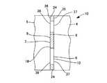
図1に示すように、本発明のハニカムフィルター10は、ハニカムセグメントの相隣接する同士4、5を、それぞれ対向する側面6、7の一部で相互に接触し、かつ非接触部12の少なくとも一部で、ハニカムセグメントの基体4、5より強度の小さい接合材24を介して相互に接合されてなるものである。
【0025】
これにより、上述したようにフィルター使用時におけるフィルター各部の熱応力を極めて低減することができるため、クラックの発生等を高度に防止することができる。
【0026】
図1に示すように、本発明におけるハニカムセグメント4、5は、多孔質の隔壁20により仕切られた複数の貫通孔21を、排ガス流入端面16及び排ガス流出端面14で、目封じ材26により互い違いに目封じした構造を備え、排ガス30を、排ガス流入端面16に開口する貫通孔21からフィルター内に流入し、強制的にフィルター内の隔壁20を通過させることにより、排ガス中の粒子状物質を捕集、除去するものである。
【0027】
ハニカムセグメント4、5の材質としては、例えば、無配向コーディエライト、配向コーディエライト、ムライト−ジルコン、ムライト、ジルコン、コーディエライト−ムライト、ムライト−チタン酸アルミニウム、クレーボンド炭化珪素、炭化珪素、金属シリコン及びジルコニア−スピネル等からなる群より選ばれた少なくとも一種を主結晶相とするセラミックスを挙げることができる。
【0028】
中でも、耐熱性とともに熱伝導性に優れ、フィルター全体の高い熱伝導性を確保してフィルター各部の熱応力を低減することができる点で、炭化珪素、又は金属シリコンと炭化珪素とを主結晶とするものが好ましい。
【0029】
本発明においては、ハニカムセグメント4、5の貫通孔21の形状、セル密度については、特に制限はなく、用途等に応じて適宜、所望の形状、セル密度とすることができる。
【0030】
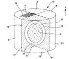
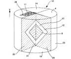
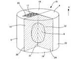
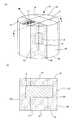
また、本発明においては、ハニカムセグメント4、5の形状についても特に制限はないが、図4〜11に示すように、例えば、円柱形状を、その中心軸31を通るように軸方向に3分割又は4分割に切断し、軸方向と垂直方向の断面形状が、扇形となるような形状のもの;図12、13に示すように、例えば、円柱形状を、軸方向に一定間隔で9分割以上に切断し、軸方向と垂直方向の断面形状が、各セグメント4で扇形、四角等の異なる形状となるもの等を挙げることができる。中でも、接触部8を、多数、かつ3次元的に設けることができるため、ハニカムフィルターの熱応力を極めて低減することができる点で、図12、13に示すようにハニカムフィルター10を9分割以上に切断した形状のハニカムセグメント4が好ましい。
【0031】
尚、ハニカムフィルター10を、内燃機関又は燃焼装置の排ガス浄化手段として用いる場合には、捕集した粒子状物質の燃焼除去を促進してフィルター再生を効果的に行うために、隔壁20に、例えば、Pt、Pd、Rh等の触媒能を有する金属を担持させることが好ましい。
【0032】
本発明のハニカムフィルター10は、上述したハニカムセグメントの相隣接する同士4、5を、それぞれ対向する側面6、7の一部で相互に接触させる構造を有するものであり、これにより、接合材24によらず又は接合材24とともにフィルター10全体の熱伝導性を確保して、各部の熱応力を低減することができる。
【0033】
ここで、本明細書において、「接触」とは、各ハニカムセグメント4、5間で熱伝導が可能であり、かつ熱膨張による変形が生じた際に、各ハニカムセグメント4、5間で接する面の位置関係が変更可能な状態を意味する。
【0034】
具体的には、例えば、図1に示すように、相隣接するハニカムセグメント4、5のうち、一のハニカムセグメント4が、他のハニカムセグメント5の側面7と対向する側面6の一部に凸部2aを有し、この凸部2aを介して隣接する他のハニカムセグメント5の側面7の一部と接触するもの;図2に示すように、相隣接するハニカムセグメント4、5のうち、一のハニカムセグメント4が、他のハニカムセグメント5の側面7と対向する側面6の一部に、ハニカムセグメント4と同一の材質からなる熱伝導部材18を配設され、この熱伝導部材18を介して、他の隣接するハニカムセグメント5の側面7の一部と接触しているもの;又は、図3に示すように、相隣接するハニカムセグメント4、5の、対向する各側面6、7の一部にそれぞれ凸部(図示せず)又は熱伝導部材18、19を設け、これらを介して相隣接するハニカムセグメント同士4、5が接触しているもの等を挙げることができる。
【0035】
中でも、設計が容易な点で、相隣接するハニカムセグメント4、5のうち、少なくとも一のハニカムセグメント4に、ハニカムセグメント4と同一の材質からなる熱伝導部材18(19)を配設して、この熱伝導部材18(19)を介して、他の隣接するハニカムセグメント5と接触させることが好ましい。
【0036】
図4〜11に示すように、接触部8及び非接触部12の配置としては、例えば、接触部8を、ハニカムフィルター10の外周面23、排ガス流入端面16及び排ガス流出端面14に接続させずにフィルター中心部に設け、非接触部12を、これらの面23、14、16に接続する部分の全部を含んで設ける例を挙げることができる。
【0037】
図4〜11に示すように、このようなハニカムフィルターでは、排ガス流入端面16、排ガス流出端面14及びハニカムフィルター10の外周面23に接続する部分全体を含んで接合材24を配設することができるため、煤の吹き抜けを効果的に防止することができる構造とすることが可能となる。また、接触部8をフィルター中心部に設けるため、フィルター全体の温度を均一化し易いとともに、接合材24を設けない部分37を、接触部8より、外側(排ガス流入端面側、排ガス流出端面側、又はハニカムフィルターの外周面側)に設けることができるため、熱応力をより効果的に低減することができる構造とすることが可能となる。更には、接触部8が、接合材24を配設する位置よりハニカムフィルター10の中心方向に位置するため、熱膨張によりフィルターに変形を生じた際でも、確実に接触状態を確保することができる。
【0038】
本発明では、接触部8の形状について特に制限はないが、例えば、ハニカムフィルター10の軸方向の断面形状が、三角形、長方形、正方形、菱形、台形、楕円、円形、トラックサークル形状、半楕円形、又は半円形の等を挙げることができる。中でも、フィルター10全体の温度を均一化し易い点で、楕円、円形、トラックサークル形状等が好ましい。
【0039】
また、本発明における接触部8の面積は、熱伝導性を高めて各ハニカムセグメント4、5の熱応力の低減下を図るという点、後述する接合材24による各ハニカムセグメント4、5の接合強度、及び接合材24による熱伝導性等を考慮して、適当な広さとすることが好ましい。
【0040】
本発明のハニカムフィルター10は、更に、ハニカムセグメントの相隣接する同士4、5を、非接触部12の一部で、ハニカムセグメント4、5の基体より強度の小さな接合材24を介して相互に接合する構造を有するものである。これにより、各ハニカムセグメント4、5を一体化しながらも、接合材24による拘束を小さくしてフィルター各部の熱応力を低減することができる。
【0041】
ここで、本明細書において「強度」とは、4点曲げ強度試験(JIS1601)により測定した値を意味する。
【0042】
本発明における接合材24は、前述したハニカムセグメント4、5の基体より強度の小さいものであればよく、フィルター10全体の熱伝導性を確保するために熱伝導性の材質とする必要はない。もっとも、接合材24を熱伝導性の材質のものにより構成して、接触部8、9と接合部35、36の両方で熱伝導性を確保することが、熱応力を低減する効果が大きい点で好ましい。
【0043】
また、フィルター使用時に高温に曝されることを考慮すると、耐熱性、耐熱衝撃性に優れる点で耐熱性無機化合物を主成分とするものが好ましく、耐熱性無機化合物としては、例えば、前述した粉末原料で用いるセラミックス及び/又は金属を含有する繊維材料又は粉体とセメント等を混合したものを挙げることができる。
【0044】
中でも、弾性率が大きく熱応力を低減する効果が大きい点で、粉末原料で用いるセラミックス及び/又は金属を含有する繊維材料とセメント等を混合したものが好ましい。また、セメントとしては、水和セメント、熱硬化セメント等を挙げることができるが、強度、作業性の点から熱硬化セメントが好ましい。
【0045】
本発明においては、図8〜11に示すように、接合材24を、非接触部12の全体に設けてもよく、図4〜7に示すように、接合材24を、非接触部12の一部に設けてもよい。
【0046】
前者の構造では、ハニカムフィルター10全体の機械的応力に対する強度を上げることができ、一方、後者の構造では、ハニカムフィルター10全体の熱応力をより低減することができる。
【0047】
また、接合材24を非接触部12の一部に設ける場合には、接合材24を設けない部分(以下、「非接合部」ということがある。)37を、接触部8より排ガス流入端面16側又は排ガス流出端面14側に設けることが好ましい。
【0048】
これにより、フィルター使用時に大きな熱応力が生じる排ガス流入端面16及び排ガス流出端面14の熱応力を集中的に低減して、ハニカムフィルター10全体の熱応力を効果的に低減することができる。
【0049】
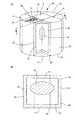
但し、煤の吹き抜けを防止するためには、図4〜7、13に示すように、接合材24を、非接触部12のうち、少なくとも、排ガス流入端面16に接続する部分全体を含んで設けることが好ましく、更に、外周面23及び排ガス流出端面14に接続する部分全体を含んで設けることがより好ましい。
【0050】
この際、接合材24は、図4、13に示すように、外周面23、排ガス流入端面16又は排ガス流出端面14から、各面23、16、14に対して垂直方向に同じ幅で設けてもよく、図5〜7に示すように、異なる幅で設けてもよい。
【0051】
また、本発明において非接合部37は、例えば、図4〜7に示すように、接触部8の形状に対応させて、長方形、正方形、菱形等の四角形、台形、円形、トラックサークル形状等の形状としてもよく、図13に示すように、接触部8の形状とは異なる形状としてもよい。
【0052】
2.ハニカムフィルターの製造方法
本発明におけるハニカムフィルターの製造方法では、まず、セラミックス及び/又は金属からなる粉末原料、バインダー及び水を混練、成形して、隔壁により仕切られた複数の貫通孔を有するハニカム構造体を得、このハニカム構造体を乾燥後、複数の貫通孔を排ガス流入側及び排ガス流出側の両端面で互い違いに目封じしてハニカムセグメント乾燥体を得る。
【0053】
セラミックス及び/又は金属からなる粉末原料としては、例えば、金属シリコン、炭化珪素、チタン、ジルコニウム、炭化ホウ素、炭化チタン、炭化ジルコニウム、窒化珪素、窒化ホウ素、窒化アルミニウム、酸化アルミニウム、酸化ジルコニウム、ムライト、コーディエライト化原料、チタン酸アルミニウム、サイアロン、カオリン、タルク、水酸化アルミニウム、溶融シリカ、及び石英よりなる群から選ばれる少なくとも一種を含むものを主原料とするものを挙げることができる。中でも、熱伝導性及び耐熱性の点で、金属シリコン及び炭化珪素、又は炭化珪素を主成分とすることが好ましい。
【0054】
バインダーとしては、例えば、ヒドロキシメチルセルロース、メチルセルロース、ヒドロキシエチルセルロース、カルボキシルメチルセルロース、又はポリビニルアルコール等を挙げることができ、これらバインダーは、一種単独で又は二種以上を組合わせて用いることができる。
【0055】
本発明では、その他に、成形助剤として一般的に使用されるエチレングリコール、デキストリン、脂肪酸石鹸、又はポリアルコール等を必要に応じて添加してもよい。
【0056】
投入する水の量は、通常、上述した粉末原料100重量部に対して、10〜40重量部程度であり、水を投入後、得られた混合原料を、真空土練機等で混練し、可塑性とする。
【0057】
成形方法は、押出成形が好ましく、例えば、ラム式押出し成形機、2軸スクリュー式連続押出成形装置等を用いて行うことができる。
【0058】
また、ハニカム構造体を乾燥する方法としては、例えば、熱風乾燥、マイクロ波乾燥、誘電乾燥、減圧乾燥、真空乾燥、凍結乾燥等を挙げることができ、中でも、誘電乾燥、マイクロ波又は熱風乾燥を単独で又は組合せて行うことが好ましい。
【0059】
また、目封じ材についても、通常用いる材料でよく、例えば、前述した粉末原料と同様のものを用いることができる。
【0060】
本発明のハニカムフィルターの製造方法では、次いで、得られたハニカムセグメント乾燥体の側面の一部に、他のハニカムセグメント乾燥体の側面に接触させる接触面を形成し、その後乾燥、焼成してハニカムセグメントを得る。
【0061】
接触面を形成する方法としては、図14に示すように、ハニカムセグメント乾燥体1を切削等の加工を行い、その側面2の一部に、凸部を設ける方法;又は図15に示すように、ハニカムセグメント乾燥体1の側面2の一部に、ハニカムセグメント乾燥体1と同材質からなる熱伝導部材18を接合する方法等を挙げることができ、中でも、接触面の設計が容易な点で後者の方法が好ましい。
【0062】
また、図16に示すように、凸部(図示せず)又は熱伝導部材18、19は、相互に接触させるハニカムセグメント乾燥体1の両方に設けてもよい。
【0063】
乾燥方法は、前述したハニカム構造体を乾燥する方法と同様であり、焼成条件についても、用いる材料の種類により適宜所望の条件を選択すればよい。
【0064】
本発明の製造方法においては、次いで、得られたハニカムセグメントの熱伝導部材又は凸部からなる接触部を、他の隣接するハニカムセグメントの対向する側面の一部と接触させ、かつ非接触部の少なくとも一部に、ハニカムセグメントの基体より強度の小さい接合材を配設して一体化する。
【0065】
接触部の配置等、及び接合材を構成する材料等については、本発明のハニカムフィルターで説明した通りであり、ここではその説明を省略する。
【0066】
但し、接合材の材料として用いる耐熱性無機化合物は、必要に応じて、有機又は無機のバインダー等を混合したものを用いることが好ましい。また、接合材は、例えば、プレート状の乾燥体、又はスラリー等のいずれを配設するものであってもよい。
【0067】
接合方法としては、例えば、非接触部の一部に、接合材を配設後、接合材の材料に応じて水和又は熱処理を選択して行うことができる。
【0068】
また、熱処理により接合する場合は、接合材の材料に応じて適宜好適な熱処理温度を選択すればよいが、一般には200〜400℃の温度で行うことが好ましい。
【0069】
また、プレート状の乾燥体からなる接合材を用いる場合は、例えば、接合材を湿らせてから圧着した後、水和又は熱処理を行えばよく、スラリー状の接合材を用いる場合は、スラリー状の接合材を塗布した後、水和又は熱処理を行えばよい。
【0070】
【実施例】
以下、本発明を具体的な実施例に基づいて更に詳細に説明するが、本発明はこれらの実施例に限定されるものではない。
【0071】
(実施例1)
セラミックス原料として、SiC粉75重量%及び金属Si粉25重量%の混合粉末を使用し、この混合粉末100重量部に、メチルセルロース及びヒドロキシプロポキシルメチルセルロースからなるバインダー6重量部と、界面活性剤0.8重量部と、水22重量部とを投入、混練機で混練して可塑性の坏土を得た。
【0072】
次いで、この坏土を押出成形して、外観形状が、円柱形状をその中心軸を通るように軸方向に4分割に切断した形状で、軸方向に対して垂直方向の断面が扇形状を有し、隔壁の厚さが、0.3mm、セル密度が、31セル/cm2である各ハニカム構造体を成形した。
【0073】
次いで、この成形体をマイクロ波及び熱風で乾燥した後、ハニカム構造体の貫通孔を、排ガス流入側及び排ガス流出側の両端面で互い違いに目封じし、ハニカムセグメント乾燥体を得た。
【0074】
次いで、ハニカムセグメント乾燥体の側面の一部に、ハニカムセグメント乾燥体と同材質からなるスラリーを塗布した後、スラリーを塗布した部分に、ハニカムセグメント乾燥体と同材質からなるプレート状の熱伝導部材を圧着、乾燥して、熱伝導部材をハニカムセグメント乾燥体に接合した。
【0075】
次いで、得られた複合セグメント乾燥体を、N2雰囲気中約400℃で脱脂し、その後Ar等の不活性雰囲気中で約1550℃で焼成し、複合ハニカムセグメントを作成した。
【0076】
次いで、複合ハニカムセグメントの熱伝導部材により構成される接触部と、隣接する他のハニカムセグメントの対向する側面の一部と接触させ、非接触部の一部に、アルミノシリケート質ファイバー、SiC粉、無機バインダー、及び水からなる接合材を配設してお互いのハニカムセグメントを接合一体化して図4に示す構造のハニカムフィルターを得た。一体化した後のハニカムフィルターの寸法は、144mmφ×152mmLで、非接触部の隙間は2mmであった。
【0077】
(実施例2)
実施例1と同様にして、ハニカムセグメント乾燥体を作成した後、得られたハニカムセグメント乾燥体を切削して、側面に凸部を設け、その後、焼成してハニカムセグメントを作成した。
【0078】
次いで、このハニカムセグメントの凸部が、隣接させる他のハニカムセグメントの側面と直接接触するように各ハニカムセグメントを組み合わせ、ハニカムセグメント同士が接触していない非接触部の一部に、実施例1と同様の接合材を配設して各ハニカムセグメントをお互いに接合、一体化して図4に示すハニカムフィルターを得た。
【0079】
得られたハニカムセグメントの寸法は、144mmφ×152mmL、隔壁の厚さが0.3mm、セル密度が31セル/cm2であった。
【0080】
(実施例3〜5)
実施例1において、それぞれ、図8、図12、又は図13に示す構造としたこと以外は、実施例1と同様にしてハニカムフィルターを得た。
【0081】
(比較例1)
実施例1において、相隣接するハニカムセグメントの、それぞれ対向する側面の全体にアルミノシリケート質ファイバー、SiC粉、無機バインダー、及び水からなる接合材を配設して、接触部を有しない構造としたこと以外は、実施例1と同様にしてハニカムフィルターを得た。
【0082】
(比較例2)
実施例1において、2つのハニカムセグメント乾燥体の各側面全体に、それぞれハニカムセグメント乾燥体と同材質からなるスラリーを塗布した後、スラリーを塗布した部分に、ハニカムセグメント乾燥体と同材質からなるプレート状の熱伝導部材を圧着、乾燥して、熱伝導部材を両方のハニカムセグメント乾燥体に接合し、接触部を有しない構造とした以外は、実施例1と同様にしてハニカムフィルターを得た。
【0083】
(評価方法)
実施例1〜5、及び比較例1、2で得られた炭化珪素質ハニカムフィルターを用い、ハニカムフィルターの外周部に把持材としてセラミック製無膨張マットを巻き、SUS409製のキャニング用缶体に押し込んでキャニング構造体とした後、ディーゼル燃料軽油の燃焼により発生させた煤を含む燃焼ガスを、前記各図面上において、ハニカム構造体の下端面(排ガス流入端面)より流入させ、上端面(排ガス流出端面)より流出させることにより、煤をハニカム構造体内に捕集した。
【0084】
次いで、一旦室温まで放冷した後、ハニカム構造体の上端面(排ガス流出端面)より900℃で一定割合の酸素を含む燃焼ガスを流入させることにより、煤を燃焼除去するフィルターの再生試験を実施した。
【0085】
このフィルター再生試験では、入口ガス温度を900℃まで上昇させる過渡時間と、捕集すす重量とを3種類設定し、フィルターの再生を実施した後、ハニカム構造体の上端面(排ガス流出端面)、下端面(排ガス流入端面)、外周面、内部のそれぞれの部位でのクラックの発生の有無を調査した。評価結果を、まとめて表1に示す。尚、表中、△はクラックが生じたことを示し、○はクラックが発生しなかったことを示す。
【0086】
【表1】
(評価)
表1からわかるように、標準条件の場合であっても、隣接するハニカムセグメント同士の対向する各側面の全体を接合材で接合した構造の比較例1では、排ガス流出端面でクラックの発生が認められ、同様に各側面の全体を、ハニカムセグメント乾燥体と同材質からなる熱伝導部材で接合した比較例2のハニカムフィルターでは、排ガス流入端面、排ガス流出端面、外周面及び内部の全てでクラックの発生が認められた。
【0088】
これに対し、相隣接するハニカムセグメント同士を、それぞれ対向する側面の一部で相互に接触させ、かつ接触する部分以外の側面の少なくとも一部で、ハニカムセグメントの基体より強度の小さい接合材を介して相互に接合する構造を有する実施例1〜5のハニカムフィルターでは、クラックの発生は認められなかった。
【0089】
また、過渡時間を短くし捕集煤重量を増加させて、温度の不均一を極めて大きくすると、本発明における各実施例でも一部にクラックの発生が認められたが、図4及び図13に示すように、接合材を非接触部の一部に設けている実施例1及び5では、図8及び図12に示すように、接合材が非接触部全体に配設されている実施例3及び4に比べ、クラックの発生は少なかった。
【0090】
また、図12、13に示すように、ハニカムフィルターを9分割して接触面を多く設けるとともに、一のハニカムセグメントの体積を小さくした構造の実施例4及び5のハニカムフィルターでは、図4及び図8に示すように、ハニカムフィルターを、その中心軸を通るように軸方向に4分割した構造の実施例1及び5のハニカムフィルターに比べ、クラックの発生は非常に少なかった。
【0091】
【発明の効果】
以上説明したように、本発明によれば、熱応力によるクラック等の発生を従来のハニカムフィルターより極めて低減することができ、特に、炭化珪素、又は金属シリコンと炭化珪素を主成分とした際に、このような特性が顕著なハニカムフィルター、及びその製造方法を提供することができる。
【図面の簡単な説明】
【図1】 本発明に係るハニカムフィルターの一の実施形態を模式的に示す断面図である。
【図2】 本発明に係るハニカムフィルターの他の実施形態を模式的に示す一部側面図である。
【図3】 本発明に係るハニカムフィルターの更に他の実施形態を模式的に示す一部側面図である。
【図4】 本発明に係るハニカムフィルターの更に他の実施形態を模式的に示す斜視図である。
【図5】 本発明に係るハニカムフィルターの更に他の実施形態を模式的に示す斜視図である。
【図6】 本発明に係るハニカムフィルターの更に他の実施形態を模式的に示す斜視図である。
【図7】 本発明に係るハニカムフィルターの更に他の実施形態を模式的に示す斜視図である。
【図8】 本発明に係るハニカムフィルターの更に他の実施形態を模式的に示す斜視図である。
【図9】 本発明に係るハニカムフィルターの更に他の実施形態を模式的に示す斜視図である。
【図10】 本発明に係るハニカムフィルターの更に他の実施形態を模式的に示す斜視図である。
【図11】 本発明に係るハニカムフィルターの更に他の実施形態を模式的に示す斜視図である。
【図12】 本発明に係るハニカムフィルターの更に他の実施形態を模式的に示しており、(a)は斜視図、(b)は(a)のY−Y’断面図である。
【図13】 本発明に係るハニカムフィルターの更に他の実施形態を模式的に示しており、(a)は斜視図、(b)は(a)のZ−Z’断面図である。
【図14】 本発明の製造方法における接合面を形成する方法の一例を模式的に示す説明図である。
【図15】 本発明の製造方法における接合面を形成する方法の他の一例を模式的に示す説明図である。
【図16】 本発明の製造方法における接合面を形成する方法の更に他の一例を模式的に示す説明図である。
【符号の説明】
1…ハニカムセグメント乾燥体、2…ハニカムセグメント乾燥体の側面、2a…凸部、4、5…ハニカムセグメント(基体)、6、7…側面、8、9…接触部、10…ハニカムフィルター、11…貫通孔、12…非接触部、14…排ガス流出端面(上端面)、15…端面外縁部、16…排ガス流入端面(下端面)、17…端面外縁部、18、19…熱伝導部材、20…隔壁、21…貫通孔、23…ハニカムフィルターの外周面、24…接合材、26…目封じ材、30…排ガス、31…中心軸、35、36…接合部、37、38…非接合部。[0001]
BACKGROUND OF THE INVENTION
The present invention relates to a honeycomb filter used in a combustion apparatus such as a boiler or an exhaust gas purification apparatus for an internal combustion engine such as a diesel engine, and a method for manufacturing the same.
[0002]
[Prior art]
The impact of particulate matter discharged from diesel engines, etc. on the environment has been greatly increased recently. Honeycomb filters for exhaust gas purification are used as an important means for collecting and removing such particulate matter. Yes.
[0003]
The honeycomb filter for exhaust gas purification usually has a structure in which a plurality of through holes partitioned by porous partition walls are alternately sealed at the exhaust gas inflow end surface and the exhaust gas outflow end surface, and the filter is formed from the through hole that opens to the exhaust gas inflow end surface. The exhaust gas that has flowed into the filter is forcibly passed through the partition walls in the filter, thereby collecting and removing particulate matter in the exhaust gas.
[0004]
By the way, due to its characteristics, such a honeycomb filter is exposed to a sudden temperature change of the exhaust gas or local high heat during use, and the temperature distribution of each part of the filter becomes non-uniform. It has been pointed out that the thermal stress increases due to the difference and causes cracks in the filter.
[0005]
In particular, when used as a means for purifying exhaust gas such as diesel engines, cracking of the filter is an important problem because it is exposed to a local high temperature by a filter regeneration process that burns and removes carbon particulates accumulated in the filter. It has become.
[0006]
Moreover, in such a filter, since the filter is exposed to extremely high temperatures, silicon carbide having excellent heat resistance or a material mainly composed of metal silicon and silicon carbide is used. Has the disadvantage that the coefficient of thermal expansion is large, there is a problem that the thermal stress generated in the filter is large and cracks and the like are more likely to occur.
[0007]
Conventionally, in order to solve such problems, the honeycomb structure is divided into a plurality of honeycomb segments, and the honeycomb segments are bonded to each other through a bonding material. Various honeycomb structures have been proposed for reducing the above.
[0008]
For example, Japanese Patent Publication No. 61-51240 discloses that a plurality of honeycomb segments made of a ceramic material have a mineral composition substantially the same as that of the honeycomb segments and have a difference in thermal expansion coefficient of 0.1% or less at 800 ° C. A thermal shock-resistant rotating heat storage body that is joined and integrated with a material is disclosed.
[0009]
However, in this rotary heat storage body, since the mineral composition of the bonding material is substantially the same as that of the honeycomb segment, the constraint of each honeycomb segment by the bonding material is still large, and the thermal stress generated in each honeycomb segment is sufficiently reduced. There was a problem that I could not.
[0010]
Japanese Patent Application Laid-Open No. 8-28246 discloses an elastic material obtained by bonding a plurality of honeycomb segments, at least three-dimensionally intersecting inorganic fibers and inorganic particles, via an inorganic binder and an organic binder. A ceramic honeycomb filter is disclosed in which the durability of the honeycomb substrate is improved by bonding with a sealing material.
[0011]
However, in this honeycomb filter, the thermal conductivity of the sealing material is small and each honeycomb segment is thermally blocked, so the temperature distribution in each part of the filter cannot be made uniform, and the thermal stress generated in the honeycomb filter The effect of reducing the above was not always sufficient.
[0012]
[Problems to be solved by the invention]
The present invention has been made in view of the above-mentioned problems, and can reduce the thermal stress of each part of the filter to highly suppress the occurrence of cracks and the like. In particular, silicon carbide, or metal silicon and silicon carbide can be used. An object of the present invention is to provide a honeycomb filter suitable for a main component and a manufacturing method thereof.
[0013]
[Means for Solving the Problems]
As a result of diligent research to solve the above-mentioned problems, the present inventor brought adjacent honeycomb segments into contact with each other directly or via a heat conducting member at a part of each side surface, thereby increasing the heat of the entire filter. In addition to ensuring conductivity, the honeycomb segments are directly connected to each other at a part of each side surface or through a heat conductive member (hereinafter also referred to as “contact portion”). The present invention has been completed by finding that at least a part of the structure can be bonded through a bonding material having a strength lower than that of the base material of the honeycomb segment to achieve the above-mentioned object.
[0014]
That is, according to the present invention, a plurality of through-holes partitioned by porous partition walls, and a plurality of honeycomb segments in which the plurality of through-holes are alternately plugged at the exhaust gas inflow end surface and the exhaust gas outflow end surface are joined. A honeycomb filter in which adjacent honeycomb segments are in contact with each other at a part of the side surfaces facing each other, and at least a part of the side surface other than the contact part is bonded with a strength lower than that of the honeycomb segment substrate. There is provided a honeycomb filter characterized by being bonded to each other via a material.
[0015]
In the present invention, the side surface portions other than the portions where the honeycomb segments contact each other directly or via the heat conducting member (hereinafter sometimes referred to as “non-contact portions”) are at least of the side surfaces having the contact portions. It is preferable to include all of the portions connected to the end surface on the exhaust gas inflow side, and include at least all of the portions connected to the exhaust gas inflow end surface, the exhaust gas outflow end surface, and the outer peripheral surface of the honeycomb filter. It is more preferable. At this time, it is preferable that the non-contact portion includes at least a portion connected to the exhaust gas inflow end surface of the side surface having the contact portion, and a bonding material is disposed on a part thereof.
[0016]
In the present invention, among the adjacent honeycomb segments, at least one honeycomb segment has a convex portion on a part of the side surface facing the side surface of the other honeycomb segment, and through the convex portion. A structure in contact with a part of the side surface of another adjacent honeycomb segment or at least one honeycomb segment among adjacent ones of the honeycomb segments is formed on a part of the side surface facing the side surface of the other honeycomb segment. A structure in which a heat conductive member made of the same material as that of the segment is provided and in contact with a part of the side surface of another adjacent honeycomb segment via the heat conductive member is preferable.
[0017]
In the present invention, the honeycomb segment is preferably composed mainly of silicon carbide, or metal silicon and silicon carbide, and the bonding material is preferably composed mainly of a heat-resistant inorganic compound. Moreover, it is preferable that a metal having catalytic ability is supported on partition walls provided between the through holes of the honeycomb segment.
[0018]
On the other hand, according to the present invention, a powder raw material made of ceramics and / or metal, a binder and water are kneaded and molded to obtain a honeycomb structure having a plurality of through holes partitioned by partition walls. After drying, a plurality of through-holes are alternately plugged at the exhaust gas inflow end surface and exhaust gas outflow end surface to obtain a honeycomb segment dried body, and a part of the side surface of the honeycomb segment dried body is made of the same material as the honeycomb segment dried body. After joining the heat conducting members, drying and firing to obtain a composite honeycomb segment, the honeycomb segments on which the heat conducting members are arranged are connected to the opposite side surfaces of other adjacent honeycomb segments. A bonding material having a strength lower than that of the substrate of the honeycomb segment is disposed and integrated with at least a part of the non-contact part. Honeycomb filter manufacturing method according to claim is provided.
[0019]
In addition, according to the present invention, a powder raw material composed of ceramics and / or metal, a binder and water are kneaded and molded to obtain a honeycomb structure having a plurality of through holes partitioned by partition walls. After drying, a plurality of through-holes are alternately plugged at the exhaust gas inflow end face and exhaust gas outflow end face to obtain a honeycomb segment dry body, and the honeycomb segment dry body is cut and convex on the side surface of the honeycomb segment dry body And then firing to obtain a honeycomb segment, the convex portion provided on the side surface of the honeycomb segment is brought into contact with a part of the opposite side surface of another adjacent honeycomb segment, and at least a part of the non-contact portion In addition, a method for manufacturing a honeycomb filter is provided, in which a bonding material having a strength lower than that of the dried honeycomb segment is disposed and integrated. Is done.
[0020]
In these production methods of the present invention, the powder raw material is preferably composed mainly of silicon carbide, or metal silicon and silicon carbide. Moreover, it is preferable that a joining material has a heat resistant inorganic compound as a main component.
[0021]
As described above, in the present invention, since at least a part of each honeycomb segment is bonded with a bonding material having a strength lower than that of the substrate of the honeycomb segment, the constraint on each honeycomb segment by the bonding material is small, and each part of the filter is It can be deformed relatively freely according to the temperature change. As a result, even if the temperature distribution is uneven in each part during use, the thermal stress generated in the filter is reduced, so that cracks can be prevented and a honeycomb filter having excellent durability can be obtained. .
[0022]
In the present invention, since the plurality of honeycomb segments are in contact with each other on a part of the surfaces facing each other, the thermal conductivity of the entire filter is ensured with or without the bonding material. The temperature distribution can be made uniform. As a result, in addition to the effects of the bonding material described above, the thermal stress of each part of the filter when the filter is used can be further reduced, and the occurrence of cracks can be highly prevented. In particular, when the honeycomb segment is mainly composed of silicon carbide having excellent thermal conductivity, or metal silicon and silicon carbide, such an effect becomes remarkable.
[0023]
DETAILED DESCRIPTION OF THE INVENTION
Hereinafter, embodiments of the present invention will be specifically described with reference to the drawings.
[0024]
1. Honeycomb filter
As shown in FIG. 1, the
[0025]
Thereby, since the thermal stress of each part of the filter when using the filter can be extremely reduced as described above, the occurrence of cracks and the like can be highly prevented.
[0026]
As shown in FIG. 1, the
[0027]
Examples of the material of the
[0028]
Among them, silicon carbide, or metal silicon and silicon carbide are used as the main crystal in that heat resistance and thermal conductivity are excellent and high thermal conductivity of the entire filter can be secured to reduce the thermal stress of each part of the filter. Those that do are preferred.
[0029]
In the present invention, the shape and cell density of the through-
[0030]
In the present invention, the shape of the
[0031]
When the
[0032]
The
[0033]
Here, in this specification, “contact” refers to a surface that can conduct heat between the
[0034]
Specifically, for example, as shown in FIG. 1, of the
[0035]
Among them, the heat conducting member 18 (19) made of the same material as the
[0036]
As shown in FIGS. 4 to 11, as the arrangement of the
[0037]
As shown in FIGS. 4 to 11, in such a honeycomb filter, it is possible to dispose the
[0038]
In the present invention, the shape of the
[0039]
The area of the
[0040]
In the
[0041]
Here, “strength” in the present specification means a value measured by a four-point bending strength test (JIS1601).
[0042]
The
[0043]
Further, considering that the filter is exposed to a high temperature, it is preferable to use a heat-resistant inorganic compound as a main component from the viewpoint of excellent heat resistance and thermal shock resistance. Examples of the heat-resistant inorganic compound include the powders described above. Examples thereof include a fiber material containing ceramics and / or metal used as a raw material or a mixture of powder and cement.
[0044]
Among them, a mixture of a fiber material containing ceramics and / or metal used as a powder raw material and cement is preferable because it has a large elastic modulus and a large effect of reducing thermal stress. Examples of the cement include hydrated cement and thermosetting cement. Thermosetting cement is preferable from the viewpoint of strength and workability.
[0045]
In this invention, as shown to FIGS. 8-11, you may provide the joining
[0046]
In the former structure, the strength against the mechanical stress of the
[0047]
Further, when the
[0048]
Thereby, the thermal stress of the exhaust gas
[0049]
However, in order to prevent the blowout of the soot, as shown in FIGS. 4 to 7 and 13, the
[0050]
At this time, as shown in FIGS. 4 and 13, the
[0051]
Further, in the present invention, the
[0052]
2. Honeycomb filter manufacturing method
In the method for manufacturing a honeycomb filter of the present invention, first, a powder raw material made of ceramics and / or metal, a binder and water are kneaded and formed to obtain a honeycomb structure having a plurality of through holes partitioned by partition walls. After the honeycomb structure is dried, a plurality of through holes are alternately plugged at both end surfaces on the exhaust gas inflow side and the exhaust gas outflow side to obtain a dried honeycomb segment.
[0053]
Examples of powder raw materials made of ceramics and / or metals include metal silicon, silicon carbide, titanium, zirconium, boron carbide, titanium carbide, zirconium carbide, silicon nitride, boron nitride, aluminum nitride, aluminum oxide, zirconium oxide, mullite, Examples of the main raw material include cordierite-forming raw materials, aluminum titanate, sialon, kaolin, talc, aluminum hydroxide, fused silica, and quartz. Among these, metal silicon and silicon carbide or silicon carbide is preferred as the main component from the viewpoint of thermal conductivity and heat resistance.
[0054]
Examples of the binder include hydroxymethyl cellulose, methyl cellulose, hydroxyethyl cellulose, carboxymethyl cellulose, and polyvinyl alcohol. These binders can be used alone or in combination of two or more.
[0055]
In the present invention, in addition, ethylene glycol, dextrin, fatty acid soap, polyalcohol or the like generally used as a molding aid may be added as necessary.
[0056]
The amount of water to be added is usually about 10 to 40 parts by weight with respect to 100 parts by weight of the powder raw material described above, and after adding water, the obtained mixed raw material is kneaded with a vacuum kneader or the like, Let it be plastic.
[0057]
The molding method is preferably extrusion molding, and can be performed using, for example, a ram type extrusion molding machine, a twin screw type continuous extrusion molding apparatus, or the like.
[0058]
Examples of the method for drying the honeycomb structure include hot air drying, microwave drying, dielectric drying, reduced pressure drying, vacuum drying, freeze drying and the like. Among them, dielectric drying, microwave or hot air drying can be used. It is preferable to carry out alone or in combination.
[0059]
Also, the sealant may be a commonly used material, for example, the same powder raw material as described above can be used.
[0060]
In the honeycomb filter manufacturing method of the present invention, a contact surface to be brought into contact with the side surface of another honeycomb segment dried body is then formed on a part of the side surface of the obtained honeycomb segment dried body, and then dried and fired to form a honeycomb. Get a segment.
[0061]
As a method of forming the contact surface, as shown in FIG. 14, the honeycomb segment dried
[0062]
Moreover, as shown in FIG. 16, you may provide a convex part (not shown) or the heat
[0063]
The drying method is the same as the method for drying the honeycomb structure described above, and the firing conditions may be appropriately selected depending on the type of material used.
[0064]
In the manufacturing method of the present invention, the contact portion made of the heat conduction member or the convex portion of the obtained honeycomb segment is then brought into contact with a part of the opposite side surface of another adjacent honeycomb segment, and the non-contact portion A bonding material having a strength lower than that of the substrate of the honeycomb segment is disposed and integrated at least partially.
[0065]
The arrangement and the like of the contact portion and the material constituting the bonding material are as described in the honeycomb filter of the present invention, and the description thereof is omitted here.
[0066]
However, as the heat-resistant inorganic compound used as a material for the bonding material, it is preferable to use a mixture of an organic or inorganic binder, if necessary. In addition, the bonding material may be, for example, a plate-like dry body or a slurry.
[0067]
As a joining method, for example, after a joining material is disposed on a part of the non-contact portion, hydration or heat treatment can be selected according to the material of the joining material.
[0068]
Moreover, when joining by heat processing, what is necessary is just to select a suitable heat processing temperature suitably according to the material of a joining material, but generally it is preferable to carry out at the temperature of 200-400 degreeC.
[0069]
Moreover, when using the joining material which consists of a plate-shaped dry body, after moistening a joining material, after crimping | compression-bonding, you may perform a hydration or heat processing, and when using a slurry-like joining material, After applying the bonding material, hydration or heat treatment may be performed.
[0070]
【Example】
EXAMPLES Hereinafter, although this invention is demonstrated further in detail based on a specific Example, this invention is not limited to these Examples.
[0071]
Example 1
As a ceramic raw material, a mixed powder of 75% by weight of SiC powder and 25% by weight of metal Si powder is used. To 100 parts by weight of the mixed powder, 6 parts by weight of a binder composed of methylcellulose and hydroxypropoxylmethylcellulose, and 0. 8 parts by weight and 22 parts by weight of water were added and kneaded with a kneader to obtain a plastic clay.
[0072]
Next, this kneaded material was extruded and the external shape was a shape obtained by cutting the cylindrical shape into four parts in the axial direction so as to pass through the central axis, and the cross section perpendicular to the axial direction had a fan shape. The partition wall thickness is 0.3 mm, and the cell density is 31 cells / cm.2 Each honeycomb structure was formed.
[0073]
Next, after the formed body was dried with microwaves and hot air, the through holes of the honeycomb structure were alternately plugged at both end surfaces on the exhaust gas inflow side and the exhaust gas outflow side to obtain a dried honeycomb segment.
[0074]
Next, after applying a slurry made of the same material as the honeycomb segment dried body to a part of the side surface of the honeycomb segment dried body, a plate-like heat conduction member made of the same material as the honeycomb segment dried body is applied to the portion where the slurry is applied. The heat conductive member was joined to the dried honeycomb segment.
[0075]
Next, the obtained composite segment dried body was treated with N.2 Degreasing was performed at about 400 ° C. in an atmosphere, and then firing was performed at about 1550 ° C. in an inert atmosphere such as Ar to form a composite honeycomb segment.
[0076]
Next, the contact portion constituted by the heat conduction member of the composite honeycomb segment is brought into contact with a part of the opposite side surface of the other adjacent honeycomb segment, and a part of the non-contact portion includes aluminosilicate fiber, SiC powder, A bonding material composed of an inorganic binder and water was disposed, and the honeycomb segments were bonded and integrated to obtain a honeycomb filter having the structure shown in FIG. The dimensions of the honeycomb filter after the integration were 144 mmφ × 152 mmL, and the clearance between the non-contact portions was 2 mm.
[0077]
(Example 2)
In the same manner as in Example 1, a honeycomb segment dried body was prepared, and the obtained honeycomb segment dried body was cut to provide convex portions on the side surfaces, and then fired to prepare honeycomb segments.
[0078]
Next, the honeycomb segments are combined so that the convex portions of the honeycomb segments are in direct contact with the side surfaces of the other adjacent honeycomb segments, and a part of the non-contact portion where the honeycomb segments are not in contact with each other is The same bonding material was disposed, and the honeycomb segments were bonded and integrated with each other to obtain a honeycomb filter shown in FIG.
[0079]
The dimensions of the obtained honeycomb segment were 144 mmφ × 152 mmL, the partition wall thickness was 0.3 mm, and the cell density was 31 cells / cm.2 Met.
[0080]
(Examples 3 to 5)
A honeycomb filter was obtained in the same manner as in Example 1 except that the structure shown in FIG. 8, FIG. 12, or FIG.
[0081]
(Comparative Example 1)
In Example 1, a bonding material composed of an aluminosilicate fiber, SiC powder, an inorganic binder, and water was disposed on the entire facing side surfaces of adjacent honeycomb segments to have a structure without a contact portion. Except for this, a honeycomb filter was obtained in the same manner as in Example 1.
[0082]
(Comparative Example 2)
In Example 1, a plate made of the same material as the honeycomb segment dry body was applied to the entire surface of each of the two honeycomb segment dry bodies after the slurry made of the same material as the honeycomb segment dry body was applied. A honeycomb filter was obtained in the same manner as in Example 1 except that the heat conductive member was pressed and dried, and the heat conductive member was joined to both dried honeycomb segment bodies to obtain a structure having no contact portion.
[0083]
(Evaluation methods)
Using the silicon carbide honeycomb filters obtained in Examples 1 to 5 and Comparative Examples 1 and 2, a ceramic non-expandable mat was wound as a gripping material around the outer periphery of the honeycomb filter and pushed into a canning body made of SUS409. Then, the combustion gas containing soot generated by the combustion of diesel fuel gas oil is introduced from the lower end surface (exhaust gas inflow end surface) of the honeycomb structure and the upper end surface (exhaust gas outflow). The soot was collected in the honeycomb structure by flowing out from the end face.
[0084]
Next, after cooling to room temperature, a regeneration test of a filter that burns and removes soot by injecting a combustion gas containing oxygen at a constant rate at 900 ° C. from the upper end surface (exhaust gas outflow end surface) of the honeycomb structure was conducted. did.
[0085]
In this filter regeneration test, the transition time for raising the inlet gas temperature to 900 ° C. and the weight to be collected are set, and after regenerating the filter, the upper end surface (exhaust gas outflow end surface) of the honeycomb structure, The presence or absence of cracks at each of the lower end surface (exhaust gas inflow end surface), outer peripheral surface, and interior was investigated. The evaluation results are summarized in Table 1. In the table, Δ indicates that a crack has occurred, and ○ indicates that no crack has occurred.
[0086]
[Table 1]
(Evaluation)
As can be seen from Table 1, even in the case of standard conditions, in Comparative Example 1 in which the entire opposing side surfaces of adjacent honeycomb segments were joined with a joining material, cracks were observed on the exhaust gas outflow end face. Similarly, in the honeycomb filter of Comparative Example 2 in which the entire side surfaces are joined by the heat conductive member made of the same material as the honeycomb segment dried body, cracks are not generated on the exhaust gas inflow end surface, the exhaust gas outflow end surface, the outer peripheral surface, and the inside. Occurrence was observed.
[0088]
On the other hand, adjacent honeycomb segments are brought into contact with each other at a part of the side surfaces facing each other, and at least a part of the side surface other than the contacted part is passed through a bonding material having a strength lower than that of the honeycomb segment substrate. No cracks were observed in the honeycomb filters of Examples 1 to 5 having the structure of joining together.
[0089]
In addition, when the transient time was shortened and the weight of the collected soot was increased to make the temperature non-uniformity extremely large, cracks were partially observed in each example in the present invention. As shown, in Examples 1 and 5 in which the bonding material is provided in a part of the non-contact portion, as shown in FIGS. 8 and 12, the bonding material is disposed in the entire non-contact portion. And 4, the occurrence of cracks was small.
[0090]
In addition, as shown in FIGS. 12 and 13, the honeycomb filter of Examples 4 and 5 having a structure in which the honeycomb filter is divided into nine parts to provide a large number of contact surfaces and the volume of one honeycomb segment is reduced. As shown in FIG. 8, the occurrence of cracks was very small compared to the honeycomb filters of Examples 1 and 5 having a structure in which the honeycomb filter was divided into four in the axial direction so as to pass through the central axis.
[0091]
【The invention's effect】
As described above, according to the present invention, the occurrence of cracks and the like due to thermal stress can be greatly reduced compared to conventional honeycomb filters, particularly when silicon carbide or metal silicon and silicon carbide are the main components. In addition, it is possible to provide a honeycomb filter having such remarkable characteristics and a manufacturing method thereof.
[Brief description of the drawings]
FIG. 1 is a cross-sectional view schematically showing one embodiment of a honeycomb filter according to the present invention.
Fig. 2 is a partial side view schematically showing another embodiment of a honeycomb filter according to the present invention.
Fig. 3 is a partial side view schematically showing still another embodiment of the honeycomb filter according to the present invention.
Fig. 4 is a perspective view schematically showing still another embodiment of the honeycomb filter according to the present invention.
Fig. 5 is a perspective view schematically showing still another embodiment of the honeycomb filter according to the present invention.
FIG. 6 is a perspective view schematically showing still another embodiment of the honeycomb filter according to the present invention.
Fig. 7 is a perspective view schematically showing still another embodiment of the honeycomb filter according to the present invention.
Fig. 8 is a perspective view schematically showing still another embodiment of the honeycomb filter according to the present invention.
FIG. 9 is a perspective view schematically showing still another embodiment of the honeycomb filter according to the present invention.
Fig. 10 is a perspective view schematically showing still another embodiment of the honeycomb filter according to the present invention.
Fig. 11 is a perspective view schematically showing still another embodiment of a honeycomb filter according to the present invention.
FIG. 12 schematically shows still another embodiment of the honeycomb filter according to the present invention, in which (a) is a perspective view and (b) is a YY ′ sectional view of (a).
FIG. 13 schematically shows still another embodiment of the honeycomb filter according to the present invention, in which (a) is a perspective view and (b) is a ZZ ′ sectional view of (a).
FIG. 14 is an explanatory view schematically showing an example of a method for forming a joint surface in the manufacturing method of the present invention.
FIG. 15 is an explanatory view schematically showing another example of a method for forming a joint surface in the manufacturing method of the present invention.
FIG. 16 is an explanatory view schematically showing still another example of a method for forming a joint surface in the manufacturing method of the present invention.
[Explanation of symbols]
DESCRIPTION OF
Claims (14)
Translated fromJapanese該ハニカムセグメントの相隣接する同士を、それぞれ対向する側面の一部で相互に接触させ、かつ該接触する部分以外の該側面の少なくとも一部で、該ハニカムセグメントの基体より強度の小さい接合材を介して相互に接合することを特徴とするハニカムフィルター。A honeycomb filter having a plurality of through-holes partitioned by porous partition walls, the plurality of through-holes being alternately sealed at the exhaust gas inflow end surface and the exhaust gas outflow end surface, and a plurality of joined honeycomb segments,
Adjacent ones of the honeycomb segments are brought into contact with each other at a part of the side surfaces facing each other, and a bonding material having a strength lower than that of the substrate of the honeycomb segment is provided at at least a part of the side surfaces other than the contact parts. Honeycomb filters characterized by being bonded to each other through.
該ハニカム構造体を乾燥後、該複数の貫通孔を排ガス流入端面及び排ガス流出端面で互い違いに目封じしてハニカムセグメント乾燥体を得、
該ハニカムセグメント乾燥体の側面の一部に、該ハニカムセグメント乾燥体と同材質からなる熱伝導部材を接合後、乾燥、焼成して複合ハニカムセグメントを得、
該熱伝導部材が配設されているハニカムセグメントを、該熱伝導部材を介して、他の隣接するハニカムセグメントの対向する側面の一部と接触させ、かつ該接触する部分以外の該側面の少なくとも一部に、該ハニカムセグメントの基体より強度の小さい接合材を配設して一体化することを特徴とするハニカムフィルターの製造方法。A honeycomb structure having a plurality of through holes partitioned by partition walls is obtained by kneading and forming a powder raw material made of ceramics and / or metal, a binder and water,
After drying the honeycomb structure, the plurality of through holes are alternately plugged at the exhaust gas inflow end surface and the exhaust gas outflow end surface to obtain a honeycomb segment dried body,
After joining a heat conductive member made of the same material as the honeycomb segment dry body to a part of the side surface of the honeycomb segment dry body, drying and firing to obtain a composite honeycomb segment,
The honeycomb segment in which the heat conducting member is disposed is brought into contact with a part of the opposite side surface of another adjacent honeycomb segment through the heat conducting member, and at least the side surface other than the contacting part A method for manufacturing a honeycomb filter, characterized in that a bonding material having a strength lower than that of the substrate of the honeycomb segment is disposed in part and integrated.
該ハニカム構造体を乾燥後、該複数の貫通孔を排ガス流入端面及び排ガス流出端面で互い違いに目封じしてハニカムセグメント乾燥体を得、
該ハニカムセグメント乾燥体を切削加工して、該ハニカムセグメント乾燥体の側面に凸部を設けた後、焼成してハニカムセグメントを得、
該ハニカムセグメントの側面に設けた該凸部を、隣接する他のハニカムセグメントの対向する側面の一部と接触させ、かつ該接触する部分以外の該側面の少なくとも一部に、該ハニカムセグメント乾燥体より強度の小さい接合材を配設して一体化することを特徴とするハニカムフィルターの製造方法。A powder raw material made of ceramics and / or metal, a binder and water are kneaded and molded to obtain a honeycomb structure having a plurality of through holes partitioned by partition walls,
After drying the honeycomb structure, the plurality of through holes are alternately plugged at the exhaust gas inflow end surface and the exhaust gas outflow end surface to obtain a honeycomb segment dried body,
Cutting the honeycomb segment dry body, providing a convex portion on the side of the honeycomb segment dry body, firing to obtain a honeycomb segment,
The protrusion provided on the side surface of the honeycomb segment is brought into contact with a part of the opposite side surface of another adjacent honeycomb segment, and the dried honeycomb segment body is provided on at least a part of the side surface other than the contacting portion. A method for manufacturing a honeycomb filter, wherein a bonding material having a lower strength is disposed and integrated.
Priority Applications (7)
| Application Number | Priority Date | Filing Date | Title |
|---|---|---|---|
| JP2001057325AJP4404497B2 (en) | 2001-03-01 | 2001-03-01 | Honeycomb filter and manufacturing method thereof |
| EP02701597AEP1366792B1 (en) | 2001-03-01 | 2002-02-27 | Honeycomb filter and method for manufacturing the same |
| DE60206141TDE60206141T2 (en) | 2001-03-01 | 2002-02-27 | Honeycomb filter and method for its production |
| PL363083APL201496B1 (en) | 2001-03-01 | 2002-02-27 | Honeycomb filter and method for manufacturing the same |
| PCT/JP2002/001800WO2002070106A1 (en) | 2001-03-01 | 2002-02-27 | Honeycomb filter and method for manufacturing the same |
| US10/258,808US6797666B2 (en) | 2001-03-01 | 2002-02-27 | Honeycomb filter and process for production thereof |
| ZA200208784AZA200208784B (en) | 2001-03-01 | 2002-10-30 | Honeycomb filter and method for manufacturing the same. |
Applications Claiming Priority (1)
| Application Number | Priority Date | Filing Date | Title |
|---|---|---|---|
| JP2001057325AJP4404497B2 (en) | 2001-03-01 | 2001-03-01 | Honeycomb filter and manufacturing method thereof |
Publications (2)
| Publication Number | Publication Date |
|---|---|
| JP2002253916A JP2002253916A (en) | 2002-09-10 |
| JP4404497B2true JP4404497B2 (en) | 2010-01-27 |
Family
ID=18917223
Family Applications (1)
| Application Number | Title | Priority Date | Filing Date |
|---|---|---|---|
| JP2001057325AExpired - LifetimeJP4404497B2 (en) | 2001-03-01 | 2001-03-01 | Honeycomb filter and manufacturing method thereof |
Country Status (7)
| Country | Link |
|---|---|
| US (1) | US6797666B2 (en) |
| EP (1) | EP1366792B1 (en) |
| JP (1) | JP4404497B2 (en) |
| DE (1) | DE60206141T2 (en) |
| PL (1) | PL201496B1 (en) |
| WO (1) | WO2002070106A1 (en) |
| ZA (1) | ZA200208784B (en) |
Families Citing this family (58)
| Publication number | Priority date | Publication date | Assignee | Title |
|---|---|---|---|---|
| JP3889194B2 (en)* | 2000-01-13 | 2007-03-07 | 日本碍子株式会社 | Honeycomb structure |
| JP4511065B2 (en)† | 2000-06-05 | 2010-07-28 | 日本碍子株式会社 | Honeycomb structure, honeycomb filter, and manufacturing method thereof |
| US20040108056A1 (en)* | 2001-10-02 | 2004-06-10 | Jun Fujita | Honeycomb structural body and method of manufacturing the structural body |
| US7534482B2 (en)* | 2002-10-07 | 2009-05-19 | Ibiden Co., Ltd. | Honeycomb structural body |
| WO2004031100A1 (en)* | 2002-10-07 | 2004-04-15 | Ibiden Co., Ltd. | Honeycomb structural body |
| EP1408003A1 (en)* | 2002-10-10 | 2004-04-14 | Matsushita Electric Industrial Co., Ltd. | Hydrogen generator and electric generator using the same |
| JP4455818B2 (en) | 2003-01-14 | 2010-04-21 | 日本碍子株式会社 | Ceramic honeycomb structure and manufacturing method thereof |
| JP4369141B2 (en)* | 2003-02-18 | 2009-11-18 | 日本碍子株式会社 | Honeycomb filter and exhaust gas purification system |
| JP4267947B2 (en)* | 2003-03-19 | 2009-05-27 | 日本碍子株式会社 | Honeycomb structure |
| JPWO2005044422A1 (en) | 2003-11-07 | 2007-11-29 | イビデン株式会社 | Honeycomb structure |
| FR2864577B1 (en)* | 2003-12-24 | 2006-05-05 | Saint Gobain Ct Recherches | FILTRATION STRUCTURE, ESPECIALLY PARTICULATE FILTER FOR EXHAUST GASES OF AN INTERNAL COMBUSTION ENGINE AND REINFORCING MEMBER FOR SUCH A STRUCTURE |
| FR2865661B1 (en)* | 2004-02-04 | 2006-05-05 | Saint Gobain Ct Recherches | FILTRATION STRUCTURE, PARTICULARLY PARTICLE FILTER FOR EXHAUST GASES OF AN INTERNAL COMBUSTION ENGINE, AND ASSOCIATED EXHAUST LINE |
| ATE496876T1 (en) | 2004-04-21 | 2011-02-15 | Dow Global Technologies Inc | METHOD FOR INCREASING THE STRENGTH OF POROUS CERAMIC BODY |
| US20090288380A1 (en)* | 2004-07-12 | 2009-11-26 | Vincent Gleize | Filtration structure, in particular a particulate filter for the exhaust gases of an internal combustion engine, and associated exhaust line |
| CN101069000B (en) | 2004-07-26 | 2010-12-08 | 陶氏环球技术公司 | Improved catalytic smoke filter |
| JP5185616B2 (en)* | 2005-03-10 | 2013-04-17 | 日本碍子株式会社 | Honeycomb structure |
| JP4434076B2 (en)† | 2005-05-23 | 2010-03-17 | 日本碍子株式会社 | Honeycomb structure |
| KR101360630B1 (en) | 2005-08-23 | 2014-02-07 | 다우 글로벌 테크놀로지스 엘엘씨 | Improved method for debindering ceramic honeycombs |
| AT502666B8 (en)* | 2005-12-16 | 2007-07-15 | Porzellanfabrik Frauenthal Gmb | METHOD AND WAVE BODY FOR CLEANING AND / OR REGENERATING GASES |
| US20080020922A1 (en)* | 2006-07-21 | 2008-01-24 | Li Cheng G | Zone catalyzed soot filter |
| PL2046696T3 (en) | 2006-07-21 | 2013-04-30 | Dow Global Technologies Llc | Imroved diesel particulate filter |
| US7596885B2 (en) | 2006-07-28 | 2009-10-06 | Corning Incorporated | Microwave drying of ceramic structures |
| DE102006043706A1 (en)* | 2006-09-18 | 2008-03-27 | Robert Bosch Gmbh | Filter element, in particular for filtering exhaust gases of an internal combustion engine |
| WO2008126333A1 (en)* | 2007-03-30 | 2008-10-23 | Ibiden Co., Ltd. | Honeycomb structure |
| JP4873326B2 (en)* | 2007-03-30 | 2012-02-08 | イビデン株式会社 | Honeycomb structure |
| CN101687132B (en) | 2007-05-04 | 2012-09-05 | 陶氏环球技术公司 | Improved honeycomb filters |
| KR101078894B1 (en)* | 2007-05-16 | 2011-11-01 | 엔지케이 인슐레이터 엘티디 | Method of preparing honeycomb segment joined body |
| JP5736173B2 (en)* | 2007-10-12 | 2015-06-17 | ダウ グローバル テクノロジーズ エルエルシー | Improved thermal shock resistant soot filter |
| KR101457146B1 (en) | 2007-11-09 | 2014-10-31 | 주식회사 칸세라 | Preparation method of silicon carbide filter |
| EP2225025B1 (en)* | 2007-12-21 | 2018-02-07 | Dow Global Technologies LLC | Method of forming a catalyzed soot filter |
| JP5683452B2 (en) | 2008-03-20 | 2015-03-11 | ダウ グローバル テクノロジーズ エルエルシー | Improved cement and method for making a thermal shock resistant ceramic honeycomb structure |
| WO2009118810A1 (en)* | 2008-03-24 | 2009-10-01 | イビデン株式会社 | Honeycomb structure |
| WO2009118813A1 (en)* | 2008-03-24 | 2009-10-01 | イビデン株式会社 | Honeycomb structure and process for producing the same |
| JP5409053B2 (en)* | 2008-04-02 | 2014-02-05 | 日本碍子株式会社 | Honeycomb structure |
| JP5292013B2 (en)* | 2008-08-07 | 2013-09-18 | 日本碍子株式会社 | Honeycomb structure |
| JP5667346B2 (en)* | 2009-03-17 | 2015-02-12 | 日本碍子株式会社 | Manufacturing method of honeycomb structure |
| KR101715427B1 (en) | 2009-06-29 | 2017-03-10 | 다우 글로벌 테크놀로지스 엘엘씨 | Cement containing multi-modal fibers for making thermal shock resistant ceramic honeycomb structures |
| CN104909831A (en) | 2009-06-29 | 2015-09-16 | 陶氏环球技术有限责任公司 | Ceramic honeycomb structure with applied inorganic skin |
| JP5833015B2 (en) | 2009-11-11 | 2015-12-16 | ダウ グローバル テクノロジーズ エルエルシー | Improved cements for obtaining thermal shock resistant ceramic honeycomb structures and methods for their preparation |
| BR112012015380A2 (en) | 2009-12-31 | 2017-09-05 | Dow Global Technologies Llc | CERAMIC HOUSEHOLD STRUCTURE AND METHOD FOR FORMING A CERAMIC HOUSEHOLD STRUCTURE |
| CN103080046B (en) | 2010-09-01 | 2016-02-17 | 陶氏环球技术有限责任公司 | For discriminating layer being applied to the method on porous ceramic filter |
| EP2611756B1 (en) | 2010-09-01 | 2017-10-25 | Dow Global Technologies LLC | Method for applying discriminating layer onto porous ceramic filters via gas-borne prefabricated porous assemblies |
| DE112012003532T5 (en) | 2011-08-26 | 2014-05-08 | Dow Global Technologies Llc | Improved process for the production of ceramic bodies |
| WO2013048850A1 (en) | 2011-09-27 | 2013-04-04 | Dow Global Technologies Llc | Cement and skinning material for ceramic honeycomb structures |
| KR20140104482A (en) | 2011-12-15 | 2014-08-28 | 다우 글로벌 테크놀로지스 엘엘씨 | Cement and skinning material based on a water-swellable clay, and method for producing segmented or skinned ceramic honeycomb structures |
| WO2013172916A1 (en) | 2012-05-18 | 2013-11-21 | Coopersurgical, Inc. | Suture passer guides and related kits and methods |
| KR20150032256A (en) | 2012-06-28 | 2015-03-25 | 다우 글로벌 테크놀로지스 엘엘씨 | Process for bonding arrays of ceramic filters |
| JP6059936B2 (en) | 2012-09-28 | 2017-01-11 | 日本碍子株式会社 | Honeycomb filter |
| JP6215333B2 (en) | 2012-10-19 | 2017-10-18 | ダウ グローバル テクノロジーズ エルエルシー | Apparatus, system, and method for lifting and moving formable and / or foldable parts |
| JP6059954B2 (en) | 2012-10-30 | 2017-01-11 | 日本碍子株式会社 | Honeycomb filter |
| JP5990095B2 (en) | 2012-12-18 | 2016-09-07 | 日本碍子株式会社 | Particulate filter |
| JP6114023B2 (en) | 2012-12-18 | 2017-04-12 | 日本碍子株式会社 | Particulate filter |
| US9702490B2 (en)* | 2013-04-30 | 2017-07-11 | Corning Incorporated | Sealing method for silicon carbide parts used at high temperatures |
| JP6285234B2 (en)* | 2014-03-25 | 2018-02-28 | 日本碍子株式会社 | Manufacturing method of honeycomb structure |
| JP7002377B2 (en)* | 2018-03-19 | 2022-01-20 | 日本碍子株式会社 | Honeycomb structure |
| JP7061491B2 (en)* | 2018-03-27 | 2022-04-28 | 日本碍子株式会社 | Honeycomb structure |
| JP7189824B2 (en)* | 2019-03-29 | 2022-12-14 | 日本碍子株式会社 | HONEYCOMB STRUCTURE AND METHOD FOR MANUFACTURING HONEYCOMB STRUCTURE |
| DE112020000119T5 (en) | 2020-02-20 | 2021-11-18 | Ngk Insulators, Ltd. | Honeycomb structure |
Family Cites Families (16)
| Publication number | Priority date | Publication date | Assignee | Title |
|---|---|---|---|---|
| JPS5546338A (en) | 1978-09-28 | 1980-04-01 | Ngk Insulators Ltd | Heat and shock resistant, revolving and heat-regenerating type ceramic heat exchanger body and its manufacturing |
| JPS577215A (en)* | 1980-06-16 | 1982-01-14 | Ngk Insulators Ltd | Preparation of ceramic honeycomb filter |
| JPS5742317A (en)* | 1980-08-28 | 1982-03-09 | Ngk Insulators Ltd | Ceramic honeycomb filter |
| US4455180A (en)* | 1981-08-24 | 1984-06-19 | Corning Glass Works | Method of fabricating a sintered and selectively plugged honeycomb structure |
| JP2505261B2 (en) | 1988-09-29 | 1996-06-05 | 日本碍子株式会社 | Ceramic heat exchanger and manufacturing method thereof |
| JPH03121213A (en)* | 1989-09-30 | 1991-05-23 | Ibiden Co Ltd | Honeycomb filter for exhaust gas purifying device |
| JP2590943Y2 (en) | 1992-10-22 | 1999-02-24 | イビデン株式会社 | Exhaust gas purification device |
| JP3390055B2 (en)* | 1993-08-18 | 2003-03-24 | イビデン株式会社 | Exhaust gas purification device |
| JP3121497B2 (en) | 1994-07-14 | 2000-12-25 | イビデン株式会社 | Ceramic structure |
| EP1382442B1 (en)* | 1996-01-12 | 2013-04-24 | Ibiden Co., Ltd. | A filter for purifying exhaust gas |
| JP3736986B2 (en) | 1998-07-28 | 2006-01-18 | イビデン株式会社 | Manufacturing method of ceramic structure |
| JP4409657B2 (en)* | 1999-03-30 | 2010-02-03 | イビデン株式会社 | Filter manufacturing method |
| JP3967034B2 (en) | 1999-03-30 | 2007-08-29 | イビデン株式会社 | Manufacturing method of ceramic filter unit |
| WO2001037971A1 (en)* | 1999-11-19 | 2001-05-31 | Ngk Insulators, Ltd. | Honeycomb structural body |
| JP3889194B2 (en)* | 2000-01-13 | 2007-03-07 | 日本碍子株式会社 | Honeycomb structure |
| JP4511065B2 (en)* | 2000-06-05 | 2010-07-28 | 日本碍子株式会社 | Honeycomb structure, honeycomb filter, and manufacturing method thereof |
- 2001
- 2001-03-01JPJP2001057325Apatent/JP4404497B2/ennot_activeExpired - Lifetime
- 2002
- 2002-02-27EPEP02701597Apatent/EP1366792B1/ennot_activeExpired - Lifetime
- 2002-02-27USUS10/258,808patent/US6797666B2/ennot_activeExpired - Lifetime
- 2002-02-27DEDE60206141Tpatent/DE60206141T2/ennot_activeExpired - Lifetime
- 2002-02-27PLPL363083Apatent/PL201496B1/enunknown
- 2002-02-27WOPCT/JP2002/001800patent/WO2002070106A1/enactiveIP Right Grant
- 2002-10-30ZAZA200208784Apatent/ZA200208784B/enunknown
Also Published As
| Publication number | Publication date |
|---|---|
| PL363083A1 (en) | 2004-11-15 |
| PL201496B1 (en) | 2009-04-30 |
| US6797666B2 (en) | 2004-09-28 |
| EP1366792A4 (en) | 2004-10-20 |
| EP1366792B1 (en) | 2005-09-14 |
| EP1366792A1 (en) | 2003-12-03 |
| DE60206141T2 (en) | 2006-05-18 |
| ZA200208784B (en) | 2003-10-30 |
| WO2002070106A1 (en) | 2002-09-12 |
| US20030138596A1 (en) | 2003-07-24 |
| DE60206141D1 (en) | 2005-10-20 |
| JP2002253916A (en) | 2002-09-10 |
Similar Documents
| Publication | Publication Date | Title |
|---|---|---|
| JP4404497B2 (en) | Honeycomb filter and manufacturing method thereof | |
| JP4408183B2 (en) | Honeycomb filter for exhaust gas purification | |
| JP3983117B2 (en) | Honeycomb structure and manufacturing method thereof | |
| JP4157304B2 (en) | Honeycomb structure | |
| JP4293753B2 (en) | Honeycomb filter | |
| EP1291061B2 (en) | Honeycomb structure and honeycomb filter, and method of producing them | |
| JP4246475B2 (en) | Manufacturing method of honeycomb structure | |
| KR100595769B1 (en) | Honeycomb Structure | |
| JP4657566B2 (en) | Honeycomb structure and manufacturing method thereof | |
| JP4421858B2 (en) | Honeycomb structure and manufacturing method thereof | |
| JP2003010616A (en) | Honeycomb structure | |
| WO2003031023A1 (en) | Honeycomb filter | |
| JP5351678B2 (en) | Honeycomb structure | |
| JP2009183835A (en) | Honeycomb filter and its manufacturing method | |
| EP2221099B1 (en) | Honeycomb structure | |
| JP2010222150A (en) | Honeycomb structure | |
| EP2684590B1 (en) | Honeycomb structure | |
| JP2004075522A (en) | Ceramic honeycomb structure | |
| JP5324423B2 (en) | Honeycomb structure | |
| JP4513063B2 (en) | Honeycomb filter | |
| US20250304504A1 (en) | Honeycomb structure, forming raw material composition, and method for producing porous body | |
| KR100607476B1 (en) | Honeycomb structure and method of manufacturing the same | |
| JP2025154844A (en) | Honeycomb structure, forming raw material composition and method for manufacturing porous body | |
| KR20090045703A (en) | Composition For Silicon Carbide Filter, Silicon Carbide Filter Comprising The Same And Method Of Making The Same |
Legal Events
| Date | Code | Title | Description |
|---|---|---|---|
| A621 | Written request for application examination | Free format text:JAPANESE INTERMEDIATE CODE: A621 Effective date:20060825 | |
| TRDD | Decision of grant or rejection written | ||
| A01 | Written decision to grant a patent or to grant a registration (utility model) | Free format text:JAPANESE INTERMEDIATE CODE: A01 Effective date:20091027 | |
| A01 | Written decision to grant a patent or to grant a registration (utility model) | Free format text:JAPANESE INTERMEDIATE CODE: A01 | |
| A61 | First payment of annual fees (during grant procedure) | Free format text:JAPANESE INTERMEDIATE CODE: A61 Effective date:20091102 | |
| FPAY | Renewal fee payment (event date is renewal date of database) | Free format text:PAYMENT UNTIL: 20121113 Year of fee payment:3 | |
| R150 | Certificate of patent or registration of utility model | Ref document number:4404497 Country of ref document:JP Free format text:JAPANESE INTERMEDIATE CODE: R150 Free format text:JAPANESE INTERMEDIATE CODE: R150 | |
| FPAY | Renewal fee payment (event date is renewal date of database) | Free format text:PAYMENT UNTIL: 20131113 Year of fee payment:4 | |
| EXPY | Cancellation because of completion of term |