JP4402458B2 - Method for determining corresponding points in 3D measurement - Google Patents
Method for determining corresponding points in 3D measurementDownload PDFInfo
- Publication number
- JP4402458B2 JP4402458B2JP2003546046AJP2003546046AJP4402458B2JP 4402458 B2JP4402458 B2JP 4402458B2JP 2003546046 AJP2003546046 AJP 2003546046AJP 2003546046 AJP2003546046 AJP 2003546046AJP 4402458 B2JP4402458 B2JP 4402458B2
- Authority
- JP
- Japan
- Prior art keywords
- points
- point
- cameras
- image
- dimensional
- Prior art date
- Legal status (The legal status is an assumption and is not a legal conclusion. Google has not performed a legal analysis and makes no representation as to the accuracy of the status listed.)
- Expired - Lifetime
Links
Images


Classifications
- G—PHYSICS
- G06—COMPUTING OR CALCULATING; COUNTING
- G06T—IMAGE DATA PROCESSING OR GENERATION, IN GENERAL
- G06T7/00—Image analysis
- G06T7/60—Analysis of geometric attributes
- G—PHYSICS
- G01—MEASURING; TESTING
- G01B—MEASURING LENGTH, THICKNESS OR SIMILAR LINEAR DIMENSIONS; MEASURING ANGLES; MEASURING AREAS; MEASURING IRREGULARITIES OF SURFACES OR CONTOURS
- G01B11/00—Measuring arrangements characterised by the use of optical techniques
- G01B11/24—Measuring arrangements characterised by the use of optical techniques for measuring contours or curvatures
- G—PHYSICS
- G06—COMPUTING OR CALCULATING; COUNTING
- G06T—IMAGE DATA PROCESSING OR GENERATION, IN GENERAL
- G06T7/00—Image analysis
- G06T7/50—Depth or shape recovery
- G06T7/55—Depth or shape recovery from multiple images
- G06T7/593—Depth or shape recovery from multiple images from stereo images
- G—PHYSICS
- G06—COMPUTING OR CALCULATING; COUNTING
- G06T—IMAGE DATA PROCESSING OR GENERATION, IN GENERAL
- G06T7/00—Image analysis
- G06T7/70—Determining position or orientation of objects or cameras
- G—PHYSICS
- G06—COMPUTING OR CALCULATING; COUNTING
- G06T—IMAGE DATA PROCESSING OR GENERATION, IN GENERAL
- G06T7/00—Image analysis
- G06T7/97—Determining parameters from multiple pictures
Landscapes
- Engineering & Computer Science (AREA)
- Physics & Mathematics (AREA)
- General Physics & Mathematics (AREA)
- Computer Vision & Pattern Recognition (AREA)
- Theoretical Computer Science (AREA)
- Geometry (AREA)
- Length Measuring Devices By Optical Means (AREA)
Description
Translated fromJapanese本発明は三次元計測に関する。本発明は様々なカメラで映された一組のポイントにおいて対応ポイントを発見する方法に関する。 The present invention relates to three-dimensional measurement. The present invention relates to a method for finding corresponding points in a set of points projected by various cameras.
コンピュータ視覚システムは様々な測定装置から得られる情報に基づいている。情報は、例えばレーザー装置、測定ヘッドを用いて、または画像からの認知を介して測定され得る。得られた情報は、例えば品質管理システムにおいて利用されてもよい。品質管理システムでは、この情報に基づいて、例えば、物体の形状の正確さ、着色エラー、または用材の節の数を決定することができる。 Computer vision systems are based on information obtained from various measuring devices. Information can be measured, for example, using a laser device, a measuring head, or via recognition from an image. The obtained information may be used in a quality management system, for example. Based on this information, the quality control system can determine, for example, the accuracy of the shape of the object, the coloring error, or the number of material nodes.
概して、コンピュータ視覚システムは複数のカメラで形成される。従来のコンピュータ視覚システムは、物体を撮影するただ1台のカメラを含んでいた。画像を現像して、様々な結論を画像から引き出すことができた。様々なアルゴリズムを用いて、画像の境界線に基づいて画像の様々なレベルを識別することができる。境界線は輝度変換に基づいて同定される。画像において形状を認知する別の方法は、それをマスク及びフィルタに接続して、ある種のポイントだけ画像から識別されるようにすることである。画像のポイントによって形成されるパターンが、データベース内のモデルと比較されて認知され得る。 In general, a computer vision system is formed of multiple cameras. Prior computer vision systems included only one camera that photographed the object. The image was developed and various conclusions could be drawn from the image. Different algorithms can be used to identify different levels of an image based on image boundaries. The boundary line is identified based on luminance conversion. Another way of recognizing a shape in an image is to connect it to a mask and filter so that only certain points are identified from the image. The pattern formed by the points of the image can be perceived as compared to the model in the database.
三次元コンピュータ視覚システムでは、何台かのカメラが必要である。三次元座標を決定するためには、少なくとも2台のカメラからの同じポイントの画像が必要である。実際三次元コンピュータ視覚システムは、数台のカメラを含む。通常、ポイントが照射を介して物体の表面上に形成される。概して、照射はレーザーを用いて実行される。ポイントは、レーザポインタである照射デバイスを用いて同じ座標系において較正されたカメラによって撮像される。異なるカメラによって撮像された同じポイントは対応ポイントと称される。ポイントの画像が少なくとも2台のカメラで生成されて対応するポイントが識別され得ると、そのポイントに対する三次元座標を決定することができる。同じ位置に対して、多くのポイントが測定される。よって、形成された一組のポイントはポイント集団と呼ばれる。A three-dimensional computer vision system requires several cameras. In order to determine the three-dimensional coordinates, images of the same point from at least two cameras are required.In fact, a three-dimensional computer vision system includes several cameras. Usually, points are formed on the surface of the object via illumination. In general, irradiation is performed using a laser. The point isimaged by a camera calibrated in the same coordinate systemusing an illumination device that is alaser pointer .The same point picked up by different cameras is called a corresponding point. Once an image of a point is generated with at least two cameras andthe corresponding point can be identified , the three-dimensional coordinates for that point can be determined. Many points are measured for the same location. Therefore, the set of points formed is called a point group.
従来の方法では、ポイント集団は同時に1つのポイントを照射することによって形成されてきた。その場合には、対応ポイントの認識に関する問題はない。物体表面上の唯一の点だけがカメラに可視であるとき、カメラは測定されたデータを同じポイントとすべて関連付けることができる。同時に1つのポイントを測定することは、ポインタが、ポイント同士の間でいつも移動しなければならないということを意味し、それがこの測定方法が低速である理由である。 In the conventional method, the point group has been formed by irradiating one point at a time. In that case, there is no problem regarding recognition of corresponding points. When only a single point on the object surface is visible to the camera, the camera can associate all measured data with the same point. Measuring one point at the same time means that the pointer must always move between the points, which is why this measurement method is slow.
本発明の目的は上述の欠点を排除し、または少なくとも大幅に軽減することである。本発明の特定の目的は、対応ポイントを関連させる新しい種類の方法を開示することである。本発明のさらなる目的は、測定の信頼性を改善し、同時に複数のポイントを使用することを可能にして測定処理を促進することである。 The object of the present invention is to eliminate or at least significantly reduce the above-mentioned drawbacks. A particular object of the present invention is to disclose a new kind of method for associating corresponding points. A further object of the present invention is to improve the reliability of the measurement and facilitate the measurement process by allowing multiple points to be used at the same time.
本発明は様々なカメラによって測定される対応ポイントを関連させる方法に関する。本発明の方法を利用するシステムは、少なくとも2台のカメラ及び測定されるべき物体の表面上のポイントを照射するために用いられる照射器を含む。概して、照射器はレーザーであるが、ポイントはカメラを用いて映されることによって測定され得るポイントを生成する他のタイプの照射器を用いて照射されてもよい。通常、いくつものポイントが照射器から形成されるマトリックスを用いて同時に照射される。さらに、システムはデータシステムを含み、データシステムは測定に必要な計算を実施するために用いられる。測定結果はデータシステムに記憶される。 The present invention relates to a method for associating corresponding points measured by various cameras. A system utilizing the method of the present invention includes at least two cameras and an illuminator that is used to illuminate a point on the surface of the object to be measured. In general, the illuminator is a laser, but the points may be illuminated using other types of illuminators that produce points that can be measured by being imaged using a camera. Usually, several points are illuminated simultaneously using a matrix formed from an illuminator. In addition, the system includes a data system, which is used to perform the calculations necessary for the measurement. The measurement result is stored in the data system.
測定されるべき物体の設計された形状は、例えば物体のCADモデルに基づいてあらかじめ既知である。物体の設計された形状が既知であるので、物体の実際の形状が測定されるべき位置または範囲を計算することができる。ポイントが選択された後に、照射器が所望の位置へ移動されて、所望のポイントが物体の表面上に照射される。 The designed shape of the object to be measured is known in advance, for example based on a CAD model of the object. Since the designed shape of the object is known, the position or range where the actual shape of the object is to be measured can be calculated. After the point is selected, the illuminator is moved to the desired position and the desired point is illuminated onto the surface of the object.
物体の表面上に照射されたポイントがカメラによって映される。ポイントのおおよその位置が、物体の三次元モデルから個別に各々のカメラに対する投射を計算することによって決定され得る。投射の座標系及びカメラによって撮られた画像の座標系は同一である。投射同士の間の対応ポイントが三次元モデルに基づいて計算され得る。The point illuminated on the surface of the object is projected by the camera. The approximate location of the points can be determined by calculating the projection for each camera individually from the three-dimensional model of the object.Coordinate system of the image taken by the projection coordinate system and the camera are identical. Corresponding points between projections can be calculated based on a three-dimensional model.
カメラによって知覚された画像において、対応ポイントが投射におけるポイントの座標に基づいて見いだされる。値または距離をシステムに入力し、カメラによって映された実際のポイントを見いだすために捜索されるべき計算されたポイントの周囲の領域又はウィンドウを画定する。所定のウィンドウの代わりに、システムは各々のポイントに対して個々にウィンドウの大きさ及び形状を計算してもよい。ウィンドウは例えば四角形または他のなんらかのパターンであってもよく、その中で捜索が実施されてポイントが配置される。一旦ポイントが発見されると、それを他のカメラによって測定された同じポイントの知覚へ投射を介して関連させ得る。実際のポイントと計算されたポイントとの間の差は、物体及び測定誤差の計算された形状と実際の形状との間の偏差からなる。 In the image perceived by the camera, corresponding points are found based on the coordinates of the points in the projection. Values or distances are entered into the system to define an area or window around the calculated point that is to be searched to find the actual point imaged by the camera. Instead of a predetermined window, the system may calculate the size and shape of the window for each point individually. The window may be a square or some other pattern, for example, in which a search is performed and points are placed. Once a point is found, it can be related via projection to the same point perception measured by other cameras. The difference between the actual point and the calculated point consists of the deviation between the calculated shape and the actual shape of the object and measurement error.
本発明を用いると、一組の照射されたポイントにおいて対応ポイントがコンピュータ視覚システムによって関連させられ得る。この恩恵として、一度に1つのポイントだけが照射される従来の解決法においてのように、照射器をしばしば移動させる必要がない。複数のポイントが同時に測定されるので、物体の測定に費やされる総使用時間がかなり減じられる。さらに、測定の信頼性が改善される。なんとなれば、各々のカメラ画像の確かに正確で同じポイントが用いられて測定されたポイントの座標を決定するからである。 With the present invention, corresponding points in a set of illuminated points can be related by a computer vision system. As a benefit of this, it is not necessary to move the illuminator often as in conventional solutions where only one point is illuminated at a time. Since multiple points are measured simultaneously, the total usage time spent measuring the object is significantly reduced. Furthermore, the reliability of the measurement is improved. This is because the exact point of each camera image is used to determine the coordinates of the measured point.
下記において、本発明を添付図面を参照し実施例を用いて詳細に説明する。 In the following, the present invention will be described in detail by way of examples with reference to the accompanying drawings.
図1に示されたシステムは、2つのカメラCAM1、CAM2、照明器LASER及びデータシステムDTEを含む。測定されるべき物体11は支持板10上に配置される。 The system shown in FIG. 1 includes two cameras CAM1, CAM2, an illuminator LASER and a data system DTE. The
図1のシステムが用いられると、測定する物体11の定位位置が物体の三次元形状に基づいて最初に決定される。定位位置が決定された後に、測定されるべきポイントまたは領域が物体の三次元モデルに基づいて選択される。一旦ポイントが選択されると、データシステムDTEは照射器LASERを所望の位置に移動させて一組のポイントを照射する。 When the system of FIG. 1 is used, the localization position of the
照射器LASERを用いて、所望の位置のポイントが照射される。概して、用いられる照射器はレーザーである。1つ以上のレーザー光線を用いて、多数の光点が形成されて物体が照射される。レーザーの代わりに、カメラで視認できる物体表面上のポイントを形成するために用いることができる他の照射方法を用いることも可能である。照射器によって照射されたポイントは、照射器を物理的に動かすことによって移動させてもよい。概して、照射されたポイントは、可動ミラーを介して光線を方向付けることによって移動される。ミラーが動かされると、照射器は変化のないままであるが、ポイントの位置が変化する。このことによって、照射器の位置が変化せず既知のままであるとき、システムの信頼性を改善する。 A point at a desired position is irradiated using the irradiator LASER. Generally, the irradiator used is a laser. Using one or more laser beams, a number of light spots are formed and the object is illuminated. Instead of a laser, it is also possible to use other illumination methods that can be used to form points on the object surface that are visible with a camera. The point irradiated by the irradiator may be moved by physically moving the irradiator. In general, the illuminated point is moved by directing the light beam through a movable mirror. When the mirror is moved, the illuminator remains unchanged, but the position of the point changes. This improves the reliability of the system when the position of the illuminator remains unchanged and known.
照射されたポイントは、照射器を用いて同じ座標系において較正されるカメラCAM1、CAM2によって撮像される。概して、少なくとも4台のカメラが用いられる。しかし、2台のカメラだけを用いても、三次元座標を測定することは可能である。必要なとき、カメラの数は増加されてもよい。カメラCAM1、CAM2によって撮られた画像は、三次元モデルから形成される投射と比較される。投射画像は物体を示す二次元の像であって、カメラの方向から視認される物体の三次元モデルからデータシステムDTEによって計算される。投射画像における照射されたポイントの位置も計算される。投射画像のポイントの位置から、カメラCAM1、CAM2と画像のポイントとの間の関連も推測され得る。The irradiated point isimaged by the cameras CAM1 and CAM2 that are calibrated in the same coordinate system using the illuminator. Generally, at least four cameras are used. However, it is possible to measure three-dimensional coordinates using only two cameras. When necessary, the number of cameras may be increased. The images taken by the cameras CAM1, CAM2 are compared with the projection formed from the 3D model. The projectedimage is a two-dimensional image showing the object, and is calculated by the data system DTE from a three-dimensional model of the object viewed from the direction of the camera. The position of the irradiated point in the projected image is also calculated. From the position of the point of the projected image, the association between the cameras CAM1, CAM2 and the point of the image can also be inferred.
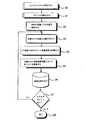
図2は図1の照射されたシステムの機能図を示す。測定手順は、同じ座標系にシステムのカメラを較正することによって開始される(ステップ20)。カメラに加えて、物体の表面上のポイントを照射するために用いられる照射器が同様に較正されなければならない(ステップ21)。較正に加えて、測定準備には物体の位置の決定が含まれる(ステップ22)。支持板に配置された物体の位置は、その既知の三次元形状に基づき決定され得る。位置決定の代わりに、物体を所定の位置に固定してもよい。 FIG. 2 shows a functional diagram of the illuminated system of FIG. The measurement procedure begins by calibrating the system's camera to the same coordinate system (step 20). In addition to the camera, the illuminator used to illuminate a point on the surface of the object must be similarly calibrated (step 21). In addition to calibration, the measurement preparation includes determining the position of the object (step 22). The position of the object placed on the support plate can be determined based on its known three-dimensional shape. Instead of determining the position, the object may be fixed at a predetermined position.
実際の測定は、所望の位置においてポイントを照射することによって開始される(ステップ23)。所望の位置はデータシステムによって選択される。データシステムは照射器の移動の指示を与える。所望の位置はデータシステムのメモリ内に順番に記憶され、その場合、同じ位置が各物体について測定される。測定のために、様々な条件が基準として設定され得る。その基準に基づいて、測定ポイントまたは測定の終了に関する決定が成される。測定は、例えば、所定のポイント数が物体に関して測定された後に停止されてもよい。The actual measurement is started by illuminating the point at the desired position (step 23). The desired location is selected by the data system. The data system gives instructions for moving the illuminator. The desired position is stored sequentially in the memory of the data system, in which case the same position is measured for each object. Variousconditions can be set as a reference for the measurement. Based on the criteria, a determination is made regarding the measurement point or the end of the measurement. The measurement may be stopped, for example, after a predetermined number of points have been measured for the object.
ポイントの位置をカメラで撮られた画像から決定することを可能にするために、ポイントの座標は二次元形式へ変換されなければならない(ステップ24)。このことは三次元モデルから投射画像を計算することによって成される。投射画像において物体はカメラの方向から二次元的に示される。ポイントの二次元座標を投射画像から計算し得る。このことはシステム内の全てのカメラに対して繰り返される。 In order to be able to determine the position of the point from the image taken with the camera, the coordinates of the point must be converted to a two-dimensional form (step 24). This is done by calculating the projection image from the three-dimensional model. In the projected image, the object is shown two-dimensionally from the direction of the camera. The two-dimensional coordinates of the points can be calculated from the projected image. This is repeated for all cameras in the system.
投射画像から得た二次元座標に基づいて、捜索が実行され、カメラで撮られた画像内にポイントを配置する(ステップ25)。例えば、ウィンドウまたは円形などのある領域が、ポイントの周囲に形成される。その後、この領域が捜索されてポイントが配置される。領域の寸法は前もって画定されている。よって、画像内で見いだされるポイントを、投射画像内の計算されたポイントに関連させ得る。よって、構築されたポイントは一組の対応ポイントを構成し、そこからポイントの実際の三次元座標が計算される。このことは照射器によって照射された全てのポイントに対して繰り返される。 A search is performed based on the two-dimensional coordinates obtained from the projected image, and points are placed in the image taken by the camera (step 25). For example, an area such as a window or a circle is formed around the point. The area is then searched for points. The dimensions of the region are predefined. Thus, the points found in the image can be related to the calculated points in the projected image. Thus, the constructed points constitute a set of corresponding points from which the actual three-dimensional coordinates of the points are calculated. This is repeated for all points illuminated by the illuminator.
測定された実際の三次元座標はデータシステムのメモリに記憶される(ステップ26)。この後、チェックが実施されて、さらなるポイントを測定する必要があるかどうかが決定される(ステップ27)。もしポイントがさらなるポイントを測定するために移動されなければならないならば、そのとき、手順を再び開始する(ステップ23)。そうでなければ、手順は終了される(ステップ28)。 The measured actual 3D coordinates are stored in the memory of the data system (step 26). After this, a check is performed to determine if further points need to be measured (step 27). If the point has to be moved to measure a further point, then the procedure is started again (step 23). Otherwise, the procedure is terminated (step 28).
図3は図1に示されたシステム1の動作を描く。図3において、ポイントは、照射器LASERによって物体31の表面上に照射される。図において、カメラCAM1及びCAM2はそれらによって生成された画像として表される。データシステムを用いて、投射が物体31の三次元モデルから両方のカメラに対して計算される。投射画像から、選択されたポイントの位置がまずまず正確に計算され得る。なんとなれば、概して、測定されるべき物体と設計されたモデルとの間の形状の偏差が小さいからである。このポイントはベクトルK1で示されるようにカメラCAM1及びCAM2に反射される。照射器LASERは同時にいくつかのポイントを照射するマトリックスを生成する。他のポイントも画像において認識できる。図3では、かかるポイントはベクトルK2によって示されるようにカメラに反射される。 FIG. 3 depicts the operation of the system 1 shown in FIG. In FIG. 3, the point is irradiated onto the surface of the
投射画像の座標に基づいて、ポイントが捜索されるべき領域が、カメラCAM1及びCAM2によって生成された画像において選択される。図4はカメラによって映された知覚を示す。投射画像において、ポイント41が計算され、その周囲の領域が捜索されて実際のポイントが配置される。投射画像において計算されたポイントを相互に関連させ得る。例では、捜索されるべき領域が正方形の形状の領域42として画定される。しかしながら、捜索領域はいかなる形状であってもよい。この領域において、実際のポイント40が検出され、このポイントを、投射画像における計算されたポイントを用いて三次元モデル上のポイントに関連させ得る。一旦対応ポイントが決定されると、ポイントの実際の三次元座標が対応ポイントに基づいて計算される。 Based on the coordinates of the projected image, the region in which the point is to be searched is selected in the images generated by the cameras CAM1 and CAM2. FIG. 4 shows the perception projected by the camera. In the projected image, the
図4では、ポイント41とポイント40との間の差を誇張して方法を視覚化する。照射されたポイント同士の間の距離が物体の形状の偏差に関して大きい実際の状況においては、前もって画像ウィンドウサイズを計算して同じウィンドウが別の競合ポイントを含まないようにすることがいつでも可能である。必要ならば、画像ウィンドウサイズの計算において、物体の全体の形状に関する既存の情報が使用される(例えば、CADモデル)。理論上は、物体の実際の形状とその設計された形状との間に大きな偏差があるならば、同じ画像ウィンドウに競合点がたまたま含まれるかもしれない。しかしながら、工業生産では、かかる物体は完全に不良であって、測定状況において、それはどんな場合でも許容範囲を上回る偏差を生成するだろう。 In FIG. 4, the method is visualized by exaggerating the difference between
本発明は上記に説明された実施例に限定されない。代わりに、多くの変化形が請求項において画定された本発明の概念の範囲内で可能である。 The present invention is not limited to the embodiments described above. Instead, many variations are possible within the scope of the inventive concept defined in the claims.
Claims (6)
Translated fromJapanese前記複数のカメラ及び前記照射器を較正する較正ステップと、
物体の位置及び向きを決定する決定ステップと、
前記物体の表面上の複数のポイントを照射する照射ステップと、
前記複数のカメラによって照射された前記複数のポイントを撮像する撮像ステップと、
計算を実行して、撮像された前記複数のポイントのうちの1つに対応する二次元投射ポイントを前記物体の三次元モデルからの画像において決定するステップと、
前記カメラによって生成された画像において計算された前記二次元投射ポイントの近くの領域を捜索して撮像された実際のポイントを見出すステップと、
対応ポイントとして前記複数のカメラによって知覚された前記実際のポイントを関連させるステップと、
前記対応ポイントに基づいて前記物体の実際の三次元座標を計算する計算ステップと、
前記複数のポイントすべてに対して前記決定するステップから前記計算ステップまでを繰り返すステップと、
前記三次元座標をメモリに記憶する記憶ステップと、
を含み、
前記照射ステップにおいて、測定されるべく照射される前記複数のポイントは、画像において形状を認知するために識別されるべきポイントであって、前記三次元モデルから前もって決定された位置にあることを特徴とする方法。A method of associatinga corresponding point insaid plurality ofset that will be measured bythe camera pointsin a computer vision systemcomprising a plurality of cameras illuminator,
A calibration step for calibrating the preKifuku number of cameras andthe illuminator,
A determining step for determining the position and orientation of the object;
Irradiating a plurality of points on the surface of the object; and
An imaging step of imagingthe plurality of points which Isairradiation by saidplurality ofcameras,
Run thecalculations, determining atwo-dimensional projection pointsthat correspond toone ofthe pluralityof pointswhich is imaged in the image from the three-dimensional model of the object,
Searching the area near thetwo-dimensional projection point calculated in the image generated by the camera to find the actual point imaged;
Associating the actual points perceived by theplurality of cameras as corresponding points;
A calculation step of calculating actual three-dimensional coordinates of the object based on the corresponding points;
Repeating from the determining step to the calculating step for all the plurality of points;
A storage step of storing the three-dimensional coordinates in a memory;
It includes,
In the irradiation step, theplurality of pointsto be baserather irradiated ismeasured, a point to be identified in order to recognize the shape in an image, thatit is in the pre-determined location from the three-dimensional model Feature method.
Applications Claiming Priority (2)
| Application Number | Priority Date | Filing Date | Title |
|---|---|---|---|
| FI20012271AFI112279B (en) | 2001-11-21 | 2001-11-21 | Method for determining offset points |
| PCT/FI2002/000928WO2003044460A1 (en) | 2001-11-21 | 2002-11-20 | Method for determining corresponding points in three-dimensional measurement |
Publications (3)
| Publication Number | Publication Date |
|---|---|
| JP2005509879A JP2005509879A (en) | 2005-04-14 |
| JP2005509879A5 JP2005509879A5 (en) | 2009-10-22 |
| JP4402458B2true JP4402458B2 (en) | 2010-01-20 |
Family
ID=8562309
Family Applications (1)
| Application Number | Title | Priority Date | Filing Date |
|---|---|---|---|
| JP2003546046AExpired - LifetimeJP4402458B2 (en) | 2001-11-21 | 2002-11-20 | Method for determining corresponding points in 3D measurement |
Country Status (7)
| Country | Link |
|---|---|
| US (1) | US7046377B2 (en) |
| EP (1) | EP1459035B1 (en) |
| JP (1) | JP4402458B2 (en) |
| AU (1) | AU2002366117A1 (en) |
| ES (1) | ES2605735T3 (en) |
| FI (1) | FI112279B (en) |
| WO (1) | WO2003044460A1 (en) |
Families Citing this family (21)
| Publication number | Priority date | Publication date | Assignee | Title |
|---|---|---|---|---|
| US7257248B2 (en)* | 2003-03-27 | 2007-08-14 | General Electric Company | Non-contact measurement system and method |
| CN101156044B (en)* | 2005-04-11 | 2011-02-02 | Faro科技有限公司 | Three-dimensional coordinate measuring apparatus |
| US20070152157A1 (en)* | 2005-11-04 | 2007-07-05 | Raydon Corporation | Simulation arena entity tracking system |
| CN100385197C (en)* | 2006-06-08 | 2008-04-30 | 天津世纪动力光电科学仪器有限公司 | Portable railless-structured optical three-D scanning measuring system and measuring method therefor |
| US20080306708A1 (en)* | 2007-06-05 | 2008-12-11 | Raydon Corporation | System and method for orientation and location calibration for image sensors |
| FI123049B (en)* | 2007-09-03 | 2012-10-15 | Mapvision Ltd Oy | System for storing artificial vision |
| US20110292406A1 (en)* | 2008-10-28 | 2011-12-01 | 3Shape A/S | Scanner with feedback control |
| CN102135417B (en)* | 2010-12-26 | 2013-05-22 | 北京航空航天大学 | A fully automatic 3D feature extraction method |
| CN102126162B (en)* | 2010-12-26 | 2013-09-25 | 北京航空航天大学 | Numerical control machine processing online measurement method |
| CN102722886B (en)* | 2012-05-21 | 2015-12-09 | 浙江捷尚视觉科技股份有限公司 | A kind of video frequency speed-measuring method based on three-dimensional scaling and Feature Points Matching |
| CN102944191B (en)* | 2012-11-28 | 2015-06-10 | 北京航空航天大学 | Method and device for three-dimensional vision measurement data registration based on planar circle target |
| CN103528520B (en)* | 2013-10-08 | 2016-03-23 | 哈尔滨工业大学 | Based on pick-up unit and the method for the synchronous operation jack-up system of binocular vision |
| CN105739339A (en)* | 2016-03-18 | 2016-07-06 | 上海斐讯数据通信技术有限公司 | Human body identification and locating method and system |
| CN106841206B (en)* | 2016-12-19 | 2018-07-24 | 大连理工大学 | Untouched online inspection method is cut in heavy parts chemical milling |
| WO2018203362A1 (en)* | 2017-05-01 | 2018-11-08 | 株式会社ニコン | Processing device and processing method |
| CN108748137B (en)* | 2018-04-11 | 2021-02-02 | 陈小龙 | Material object scanning modeling method and application thereof |
| FR3082934B1 (en)* | 2018-06-26 | 2021-10-08 | Safran Nacelles | LASER PROJECTION DEVICE AND METHOD FOR MANUFACTURING PARTS FROM COMPOSITE MATERIAL BY DRAPING |
| CN110702025B (en)* | 2019-05-30 | 2021-03-19 | 北京航空航天大学 | A grating type binocular stereo vision three-dimensional measurement system and method |
| CN111578866B (en)* | 2020-06-16 | 2021-04-20 | 大连理工大学 | A spatial pose calibration method for combined measurement of multi-line laser sensors |
| CN114782434B (en)* | 2022-06-20 | 2022-09-27 | 青岛大学附属医院 | A kind of endoscope cooperative target localization method and system |
| CN115792869B (en)* | 2022-12-27 | 2025-02-18 | 江苏集萃智能光电系统研究所有限公司 | A joint calibration method and device for 2D area array camera and line laser 3D sensor |
Family Cites Families (21)
| Publication number | Priority date | Publication date | Assignee | Title |
|---|---|---|---|---|
| US4188544A (en)* | 1977-08-22 | 1980-02-12 | Weyerhaeuser Company | Method and apparatus for automatically processing a workpiece employing calibrated scanning |
| US4294544A (en) | 1979-08-03 | 1981-10-13 | Altschuler Bruce R | Topographic comparator |
| EP0159187A3 (en) | 1984-04-17 | 1987-07-15 | Simon-Carves Limited | A surface topography measuring system |
| JPH0726828B2 (en) | 1986-04-18 | 1995-03-29 | 株式会社トプコン | Shape measuring device |
| FR2629198B1 (en) | 1988-03-25 | 1994-07-08 | Kreon Ingenierie Marketing | METHOD FOR DETERMINING AND RECONSTRUCTING THE SPATIAL COORDINATES OF EACH POINT OF A SET OF POINTS SAMPLING A THREE-DIMENSIONAL SURFACE, AND METHOD FOR PRODUCING A THREE-DIMENSIONAL IMAGE OF THIS SURFACE FROM COORDINATE DETAILS |
| JPH02110789A (en) | 1988-10-20 | 1990-04-23 | Niigata Eng Co Ltd | Shape recognition method for 3D objects |
| US4979815A (en) | 1989-02-17 | 1990-12-25 | Tsikos Constantine J | Laser range imaging system based on projective geometry |
| US5383013A (en) | 1992-09-18 | 1995-01-17 | Nec Research Institute, Inc. | Stereoscopic computer vision system |
| US5388059A (en)* | 1992-12-30 | 1995-02-07 | University Of Maryland | Computer vision system for accurate monitoring of object pose |
| US5532816A (en)* | 1994-03-15 | 1996-07-02 | Stellar Industries, Inc. | Laser tracking wheel alignment measurement apparatus and method |
| US6147760A (en) | 1994-08-30 | 2000-11-14 | Geng; Zheng Jason | High speed three dimensional imaging method |
| JP3478606B2 (en)* | 1994-10-12 | 2003-12-15 | キヤノン株式会社 | Stereoscopic image display method and apparatus |
| US6122065A (en) | 1996-08-12 | 2000-09-19 | Centre De Recherche Industrielle Du Quebec | Apparatus and method for detecting surface defects |
| JP3372014B2 (en) | 1996-08-29 | 2003-01-27 | ダイハツ工業株式会社 | Missing parts inspection equipment for engine external parts |
| JPH10283473A (en) | 1997-04-03 | 1998-10-23 | Sumitomo Electric Ind Ltd | Chipping inspection method and apparatus by image processing |
| AU8472898A (en) | 1997-06-30 | 1999-01-19 | Semiconductor Technologies & Instruments, Inc. | Method and apparatus for inspecting a workpiece |
| US6173070B1 (en) | 1997-12-30 | 2001-01-09 | Cognex Corporation | Machine vision method using search models to find features in three dimensional images |
| US6789039B1 (en)* | 2000-04-05 | 2004-09-07 | Microsoft Corporation | Relative range camera calibration |
| JP4089148B2 (en)* | 2000-10-17 | 2008-05-28 | 株式会社日立製作所 | Interpreting service method and interpreting service device |
| US6492651B2 (en)* | 2001-02-08 | 2002-12-10 | 3D Systems, Inc. | Surface scanning system for selective deposition modeling |
| US6868194B2 (en)* | 2001-12-19 | 2005-03-15 | General Electric Company | Method for the extraction of image features caused by structure light using image reconstruction |
- 2001
- 2001-11-21FIFI20012271Apatent/FI112279B/ennot_activeIP Right Cessation
- 2002
- 2002-11-20AUAU2002366117Apatent/AU2002366117A1/ennot_activeAbandoned
- 2002-11-20JPJP2003546046Apatent/JP4402458B2/ennot_activeExpired - Lifetime
- 2002-11-20ESES02803416.3Tpatent/ES2605735T3/ennot_activeExpired - Lifetime
- 2002-11-20EPEP02803416.3Apatent/EP1459035B1/ennot_activeExpired - Lifetime
- 2002-11-20USUS10/496,144patent/US7046377B2/ennot_activeExpired - Lifetime
- 2002-11-20WOPCT/FI2002/000928patent/WO2003044460A1/enactiveApplication Filing
Also Published As
| Publication number | Publication date |
|---|---|
| US7046377B2 (en) | 2006-05-16 |
| FI20012271L (en) | 2003-05-22 |
| EP1459035A1 (en) | 2004-09-22 |
| JP2005509879A (en) | 2005-04-14 |
| AU2002366117A1 (en) | 2003-06-10 |
| US20050012056A1 (en) | 2005-01-20 |
| FI112279B (en) | 2003-11-14 |
| ES2605735T3 (en) | 2017-03-16 |
| WO2003044460A1 (en) | 2003-05-30 |
| EP1459035B1 (en) | 2016-08-31 |
| FI20012271A0 (en) | 2001-11-21 |
Similar Documents
| Publication | Publication Date | Title |
|---|---|---|
| JP4402458B2 (en) | Method for determining corresponding points in 3D measurement | |
| JP4290733B2 (en) | Three-dimensional shape measuring method and apparatus | |
| US7486805B2 (en) | Method and optical system for measuring the topography of a test object | |
| JP5943547B2 (en) | Apparatus and method for non-contact measurement | |
| CN109938837B (en) | Optical tracking system and optical tracking method | |
| US7990545B2 (en) | Surface measurement of in-vivo subjects using spot projector | |
| EP2568253B1 (en) | Structured-light measuring method and system | |
| CN103649674A (en) | Measurement device and information processing device | |
| WO2004044522A1 (en) | Three-dimensional shape measuring method and its device | |
| EP3049756B1 (en) | Modeling arrangement and method and system for modeling the topography of a three-dimensional surface | |
| JP2004340840A (en) | Distance measuring device, distance measuring method, and distance measuring program | |
| JP2012215394A (en) | Three-dimensional measuring apparatus and three-dimensional measuring method | |
| JP2005509877A (en) | Computer vision system calibration method and system | |
| US20250264418A1 (en) | Method and system for inspecting a surface with artificial intelligence assist | |
| CN117640915A (en) | Laser scanner with stereoscopic camera field of view for improved selective feature scanning | |
| US7046839B1 (en) | Techniques for photogrammetric systems | |
| JP3081035B2 (en) | 3D coordinate measuring device | |
| JP2000205821A (en) | Instrument and method for three-dimensional shape measurement | |
| JP3408237B2 (en) | Shape measuring device | |
| WO2003042924A1 (en) | Connection of point clouds measured by a computer vision system | |
| CN107835931A (en) | Method for monitoring linear dimensions of three-dimensional solids | |
| JP2020197495A (en) | Information processing apparatus, measuring device, information processing method, program, system, and method for manufacturing article | |
| CN119087413B (en) | External parameter calibration matrix evaluation device and method for camera and radar and electronic equipment | |
| JP2002031511A (en) | Three-dimensional digitizer | |
| JP2006308452A (en) | Method and apparatus for measuring three-dimensional shape |
Legal Events
| Date | Code | Title | Description |
|---|---|---|---|
| A621 | Written request for application examination | Free format text:JAPANESE INTERMEDIATE CODE: A621 Effective date:20051012 | |
| A131 | Notification of reasons for refusal | Free format text:JAPANESE INTERMEDIATE CODE: A131 Effective date:20081028 | |
| A521 | Request for written amendment filed | Free format text:JAPANESE INTERMEDIATE CODE: A523 Effective date:20090127 | |
| A524 | Written submission of copy of amendment under article 19 pct | Free format text:JAPANESE INTERMEDIATE CODE: A524 Effective date:20090127 | |
| A131 | Notification of reasons for refusal | Free format text:JAPANESE INTERMEDIATE CODE: A131 Effective date:20090602 | |
| A601 | Written request for extension of time | Free format text:JAPANESE INTERMEDIATE CODE: A601 Effective date:20090831 | |
| A524 | Written submission of copy of amendment under article 19 pct | Free format text:JAPANESE INTERMEDIATE CODE: A524 Effective date:20090901 | |
| A602 | Written permission of extension of time | Free format text:JAPANESE INTERMEDIATE CODE: A602 Effective date:20090907 | |
| TRDD | Decision of grant or rejection written | ||
| A01 | Written decision to grant a patent or to grant a registration (utility model) | Free format text:JAPANESE INTERMEDIATE CODE: A01 Effective date:20091013 | |
| A01 | Written decision to grant a patent or to grant a registration (utility model) | Free format text:JAPANESE INTERMEDIATE CODE: A01 | |
| A61 | First payment of annual fees (during grant procedure) | Free format text:JAPANESE INTERMEDIATE CODE: A61 Effective date:20091029 | |
| R150 | Certificate of patent or registration of utility model | Ref document number:4402458 Country of ref document:JP Free format text:JAPANESE INTERMEDIATE CODE: R150 Free format text:JAPANESE INTERMEDIATE CODE: R150 | |
| FPAY | Renewal fee payment (event date is renewal date of database) | Free format text:PAYMENT UNTIL: 20121106 Year of fee payment:3 | |
| FPAY | Renewal fee payment (event date is renewal date of database) | Free format text:PAYMENT UNTIL: 20131106 Year of fee payment:4 | |
| R250 | Receipt of annual fees | Free format text:JAPANESE INTERMEDIATE CODE: R250 | |
| R250 | Receipt of annual fees | Free format text:JAPANESE INTERMEDIATE CODE: R250 | |
| R250 | Receipt of annual fees | Free format text:JAPANESE INTERMEDIATE CODE: R250 | |
| R250 | Receipt of annual fees | Free format text:JAPANESE INTERMEDIATE CODE: R250 | |
| R250 | Receipt of annual fees | Free format text:JAPANESE INTERMEDIATE CODE: R250 | |
| R250 | Receipt of annual fees | Free format text:JAPANESE INTERMEDIATE CODE: R250 | |
| R250 | Receipt of annual fees | Free format text:JAPANESE INTERMEDIATE CODE: R250 | |
| R250 | Receipt of annual fees | Free format text:JAPANESE INTERMEDIATE CODE: R250 | |
| R250 | Receipt of annual fees | Free format text:JAPANESE INTERMEDIATE CODE: R250 | |
| R250 | Receipt of annual fees | Free format text:JAPANESE INTERMEDIATE CODE: R250 | |
| R250 | Receipt of annual fees | Free format text:JAPANESE INTERMEDIATE CODE: R250 | |
| EXPY | Cancellation because of completion of term |