JP4402448B2 - Display monitor stand - Google Patents
Display monitor standDownload PDFInfo
- Publication number
- JP4402448B2 JP4402448B2JP2003426944AJP2003426944AJP4402448B2JP 4402448 B2JP4402448 B2JP 4402448B2JP 2003426944 AJP2003426944 AJP 2003426944AJP 2003426944 AJP2003426944 AJP 2003426944AJP 4402448 B2JP4402448 B2JP 4402448B2
- Authority
- JP
- Japan
- Prior art keywords
- display monitor
- attached
- elevating plate
- case
- guide hole
- Prior art date
- Legal status (The legal status is an assumption and is not a legal conclusion. Google has not performed a legal analysis and makes no representation as to the accuracy of the status listed.)
- Expired - Fee Related
Links
Images


Classifications
- F—MECHANICAL ENGINEERING; LIGHTING; HEATING; WEAPONS; BLASTING
- F16—ENGINEERING ELEMENTS AND UNITS; GENERAL MEASURES FOR PRODUCING AND MAINTAINING EFFECTIVE FUNCTIONING OF MACHINES OR INSTALLATIONS; THERMAL INSULATION IN GENERAL
- F16M—FRAMES, CASINGS OR BEDS OF ENGINES, MACHINES OR APPARATUS, NOT SPECIFIC TO ENGINES, MACHINES OR APPARATUS PROVIDED FOR ELSEWHERE; STANDS; SUPPORTS
- F16M11/00—Stands or trestles as supports for apparatus or articles placed thereon ; Stands for scientific apparatus such as gravitational force meters
- F16M11/20—Undercarriages with or without wheels
- F16M11/24—Undercarriages with or without wheels changeable in height or length of legs, also for transport only, e.g. by means of tubes screwed into each other
- F16M11/26—Undercarriages with or without wheels changeable in height or length of legs, also for transport only, e.g. by means of tubes screwed into each other by telescoping, with or without folding
- F16M11/28—Undercarriages for supports with one single telescoping pillar
- F16M11/30—Undercarriages for supports with one single telescoping pillar with co-moving side-struts
- F—MECHANICAL ENGINEERING; LIGHTING; HEATING; WEAPONS; BLASTING
- F16—ENGINEERING ELEMENTS AND UNITS; GENERAL MEASURES FOR PRODUCING AND MAINTAINING EFFECTIVE FUNCTIONING OF MACHINES OR INSTALLATIONS; THERMAL INSULATION IN GENERAL
- F16M—FRAMES, CASINGS OR BEDS OF ENGINES, MACHINES OR APPARATUS, NOT SPECIFIC TO ENGINES, MACHINES OR APPARATUS PROVIDED FOR ELSEWHERE; STANDS; SUPPORTS
- F16M11/00—Stands or trestles as supports for apparatus or articles placed thereon ; Stands for scientific apparatus such as gravitational force meters
- F16M11/02—Heads
- F16M11/04—Means for attachment of apparatus; Means allowing adjustment of the apparatus relatively to the stand
- F16M11/06—Means for attachment of apparatus; Means allowing adjustment of the apparatus relatively to the stand allowing pivoting
- F16M11/10—Means for attachment of apparatus; Means allowing adjustment of the apparatus relatively to the stand allowing pivoting around a horizontal axis
- F—MECHANICAL ENGINEERING; LIGHTING; HEATING; WEAPONS; BLASTING
- F16—ENGINEERING ELEMENTS AND UNITS; GENERAL MEASURES FOR PRODUCING AND MAINTAINING EFFECTIVE FUNCTIONING OF MACHINES OR INSTALLATIONS; THERMAL INSULATION IN GENERAL
- F16M—FRAMES, CASINGS OR BEDS OF ENGINES, MACHINES OR APPARATUS, NOT SPECIFIC TO ENGINES, MACHINES OR APPARATUS PROVIDED FOR ELSEWHERE; STANDS; SUPPORTS
- F16M11/00—Stands or trestles as supports for apparatus or articles placed thereon ; Stands for scientific apparatus such as gravitational force meters
- F16M11/02—Heads
- F16M11/18—Heads with mechanism for moving the apparatus relatively to the stand
- F—MECHANICAL ENGINEERING; LIGHTING; HEATING; WEAPONS; BLASTING
- F16—ENGINEERING ELEMENTS AND UNITS; GENERAL MEASURES FOR PRODUCING AND MAINTAINING EFFECTIVE FUNCTIONING OF MACHINES OR INSTALLATIONS; THERMAL INSULATION IN GENERAL
- F16M—FRAMES, CASINGS OR BEDS OF ENGINES, MACHINES OR APPARATUS, NOT SPECIFIC TO ENGINES, MACHINES OR APPARATUS PROVIDED FOR ELSEWHERE; STANDS; SUPPORTS
- F16M11/00—Stands or trestles as supports for apparatus or articles placed thereon ; Stands for scientific apparatus such as gravitational force meters
- F16M11/20—Undercarriages with or without wheels
- F16M11/2007—Undercarriages with or without wheels comprising means allowing pivoting adjustment
- F16M11/2021—Undercarriages with or without wheels comprising means allowing pivoting adjustment around a horizontal axis
- F—MECHANICAL ENGINEERING; LIGHTING; HEATING; WEAPONS; BLASTING
- F16—ENGINEERING ELEMENTS AND UNITS; GENERAL MEASURES FOR PRODUCING AND MAINTAINING EFFECTIVE FUNCTIONING OF MACHINES OR INSTALLATIONS; THERMAL INSULATION IN GENERAL
- F16M—FRAMES, CASINGS OR BEDS OF ENGINES, MACHINES OR APPARATUS, NOT SPECIFIC TO ENGINES, MACHINES OR APPARATUS PROVIDED FOR ELSEWHERE; STANDS; SUPPORTS
- F16M2200/00—Details of stands or supports
- F16M2200/04—Balancing means
- F16M2200/041—Balancing means for balancing rotational movement of the head
Landscapes
- Engineering & Computer Science (AREA)
- General Engineering & Computer Science (AREA)
- Mechanical Engineering (AREA)
- Devices For Indicating Variable Information By Combining Individual Elements (AREA)
Description
Translated fromJapaneseこの発明は、例えばノートパソコン、卓上に置く液晶モニター、薄型モニターのようなディスプレイモニターに用いて好適なディスプレイモニター用スタンドに関する。 The present invention relates to a display monitor stand suitable for use in a display monitor such as a notebook computer, a liquid crystal monitor placed on a table, or a thin monitor.
従来、卓上へ置いたディスプレイモニターの高さや角度を調節するために、下記特許文献に示されたさまざまなディスプレイモニター用スタンドが公知である。 Conventionally, in order to adjust the height and angle of a display monitor placed on a table, various display monitor stands disclosed in the following patent documents are known.
これらの特許文献に示されたディスプレイモニター用スタンドの高さを調節する昇降機構は、いずれもフリクション機構とコンプレッションスプリング、引張スプリング、及びコンストンスプリングから成る弾性手段を組み合わせたものであった。 All of the elevating mechanisms for adjusting the height of the display monitor stand shown in these patent documents are a combination of a friction mechanism, an elastic means including a compression spring, a tension spring, and a conston spring.
これらのフリクション機構と弾性手段を組み合わせて成る昇降機構を有するディスプレイモニター用スタンドは、弾性手段の伸縮動作、及びフリクション機構の摩擦時に異音が発生し易い上に、弾性手段の持つばね特性により、スタンドの厚さを減じることが困難であり、スタンドをコンパクトでスマートに構成するにつき限界があった。 A display monitor stand having a lifting mechanism composed of a combination of these friction mechanisms and elastic means is liable to generate abnormal noise during expansion and contraction of the elastic means and friction of the friction mechanism, and due to the spring characteristics of the elastic means, It was difficult to reduce the thickness of the stand, and there was a limit to the compact and smart construction of the stand.
この発明の目的は、とくに昇降機構に工夫を凝らすことによってスタンドの昇降動作時の異音の発生を防止し、薄型化を図ることのできる、ディスプレイモニター用スタンドを提供せんとするにある。 An object of the present invention is to provide a display monitor stand that can prevent the generation of noise during the lifting operation of the stand by devising the lifting mechanism, and can be thinned.
上述した目的を達成するためにこの発明は、台座部へ取り付けられるベース部材と、このベース部材より立設された支持ケースのケース本体と、両側部にスライド部材を有し、このスライド部材を介して前記支持ケースのケース本体に対し上下方向へ摺動可能に挿入された昇降板と、この昇降板の上部にチルト機構を介して取り付けられたディスプレイモニター取付用のブラケットと、前記昇降板に取り付けたラック部材と、このラック部材と噛合する駆動ピニオンギアを有し前記支持ケースのケース本体に固定して取り付けた一方向の回転時に回転トルクを発生させるトルクリミッターとから成り、前記昇降板はその中央部に上下方向へ伸張するガイド穴を設け、前記ラック部材を前記ガイド穴の内側に沿って設け、前記トルクリミッター及び又は駆動ピニオンギアが前記ガイド穴を貫通していることを特徴とする。In order to achieve the above-described object, the present invention includes a base memberattached to apedestal portion,a case main body of asupport case erected from the base member, and slide members on both side portions. The lifting plate is slidably inserted in the vertical direction with respect tothe case body of the support case, the display monitor mounting bracket is mounted on the lifting plate via a tilt mechanism, and is mounted on the lifting plate. a rack membermade ofthis rack member and meshing with saidsupporting case unidirectional torque limiter for generating a rotation torque during rotation of the mounted and fixed to thecase body of a drivingpiniongear,the elevating plate thereof A guide hole extending in the vertical direction is provided at the center, and the rack member is provided along the inside of the guide hole, and the torque limiter is provided. Beauty or the drive pinion gear is characterizedin that through said guide hole.
その際にこの発明は、前記支持ケースのケース本体を前記ベース部材に対し、チルト機構を介して前後方向へ揺動可能に取り付けることができる。In this case, according to the present invention,the case main body of thesupport case can be attached to the base member so as to be swingable in the front-rear direction via a tilt mechanism.
この発明はまた、前記ブラケットは、前記昇降板へチルト機構を介して前後方向へ揺動可能に取り付けられていることを特徴とする。The present invention is also characterized in that the bracket is attached to thelifting plate so as to be swingable in the front-rear direction via a tilt mechanism .
この発明はまた、前記駆動ピニオンギアとラック部材の一方或は双方を合成樹脂製とすることができる。In the present invention, one or both of the drivepinion gear and the rack member can be made of synthetic resin.
この発明はさらに、前記スライド部材は、前記昇降板の両側部に前後方向から取り付けられる一対の部材で構成されていることを特徴とする。In the invention, it is furtherpreferable that the slide member is composed of a pair of members that are attached to both sides of the elevating plate from the front-rear direction .
そしてこの発明は、前記支持ケースのケース本体には、前記昇降板に設けたガイド穴と係合して、前記昇降板の上下方向の摺動を規制するストッパー部材が設けられていることを特徴とする。According to the present invention,the case main body of the support case is provided with a stopper member that engages with a guide hole provided in the elevating plate and restricts sliding of the elevating plate in the vertical direction. And
この発明によれば、昇降機構に薄型のトルクリミッターを用いることにより、全体として薄型化を図り、このトルクリミッターを動作させる駆動ギヤとこの駆動ギヤと噛合するラックギヤを各々合成樹脂製のものとすることにより動作時に異音の発生を防止することができるものである。 According to this invention, by using a thin torque limiter for the lifting mechanism, the overall thickness is reduced, and the drive gear for operating the torque limiter and the rack gear meshing with the drive gear are each made of synthetic resin. Thus, it is possible to prevent the generation of abnormal noise during operation.
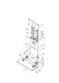
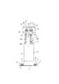
図面はこの発明の一実施の形態を示し、指示記号1で示したものは、ベース部材であり、図1に想像線で示した台座部Aに取り付けられる。このベース部材1には所定間隔を空けて公知構成を有する一対の第1チルト機構2,2の各取付部材3,3が所定間隔を空けて取付ビス3a,3a・・・で取り付けられており、この第1チルト機構2,2の各ブラケット4,4に昇降機構Bの支持ケース5のケース本体6の下部両側部が取付ビス4a,4a・・・で取り付けられている。このケース本体6は合成樹脂製の成型品で、前側に前蓋7が、下部側に下部蓋8が各々取付ビス7a,7a・・・と8a,8a・・・で取り付けられている。第1チルト機構2,2は、取付部材3,3とブラケット4,4以外に、シャフト9と1枚又は複数枚のフリクションワッシャー10と、同じく1枚又は複数枚のスプリングワッシャー11、押えワッシャー12、及び締付ナット13とから成る公知構成のもので、締付ナット13に代えてシャフト9の端部をかしめて必要なフリクショントルクを得るようにしても良い。また、この第1チルト機構2,2の締付ナット13を設けた側をケース本体6内に収納させてしまう構成であっても良い。 The drawings show an embodiment of the present invention.
指示記号14で示したものは、図1に想像線で示したディスプレイモニターCを取り付けるモニター用ブラケットであり、このモニター用ブラケット14の両下端部は、一対の第2チルト機構16,16の各ブラケット17,17に取付ビス14a,14a・・・で固着されている。この第2チルト機構16,16の取付部材18,18は、支持ケース5内に上下方向へ摺動可能に挿入された昇降板19の上部両端部へ取付ビス17a,17a・・・で固着されている。 What is indicated by an
第2チルト機構16,16は、第1チルト機構2と同じ構成であり、ブラケット17,17、取付部材18,18の外に、シャフト20と、1枚或は複数枚のフリクションワッシャー21と、同じく1枚或は複数枚のスプリングワッシャー22と、押えワッシャー23と、及び締付ナット24とから成る公知構成のもので、締付ナット24に代えてシャフト20の端部を、必要なフリクショントルクを得るようにしてかしめても良い。 The
昇降板19には、中央部を上下に渡ってくり抜いてガイド穴19aが形成されると共に、両端部の両面にスライド部材25a,25b・26a,26bを取り付け、支持ケース5内に上下方向へ摺動可能に挿入されている。昇降板19には、さらにガイド穴19aに沿って、例えばPOM等の合成樹脂製のラック部材27が取付ビス27a,27a・・・で取り付けられている。尚、指示記号25c,26cのものは、波ワッシャーであり、昇降板19のスライド操作力を調整する機能を営むものである。 A
支持ケース5のケース本体6の内側には、支軸28が突設され、この支軸28にトルクリミッター29が係止されている。このトルクリミッター29は一方向の回転時のみ、トルクを発生させる構成のもので、CS止め輪、或はEリング30によって支軸28に抜止係止されると共に、前蓋7に設けた切欠部7bに嵌入されることによって回転規制されている。尚、このトルクリミッター29は、切欠部7bや支軸28によらず、支持ケース5に他の手段で固定させても良い。 A support shaft 28 protrudes from the inside of the
そして、このトルクリミッター29の回転部には、例えばPOM等の合成樹脂製の駆動ピニオンギア31が取り付けられ、この駆動ピニオンギア31がラック部材27と噛合している。なお、前蓋7の切欠部7bから内側へ折り曲げて設けられたものは、ストッパー部材32であり、その先端を昇降板19に設けたガイド穴19aに嵌入させている。Then, the rotating part of the
したがって、この発明に係るディスプレイモニター用スタンドに取り付けたディスプレイモニターCの前後方向の角度調節は、第1及び第2チルト機構2,2・16,16により、任意に行うことができ、高さ調節は、昇降板19が支持ケース5に対し上下方向へ摺動することによってなされる。その際に、ディスプレイモニターCの上方向の移動は、トルクリミッター29に回転トルクが発生しない構成であるので、駆動ピニオンギア31がラック部材27上を回転しつつなされる。ディスプレイモニターCの下方向の移動時には、ラック部材27に案内されて回転する駆動ピニオンギア31が、トルクリミッター29が創出する回転トルクによる負荷を受けるので、このトルクリミッター29の回転トルクに抗して下降し、手を離したところで、任意に停止し安定保持状態を保つことができるものである。Therefore, the angle adjustment in the front-rear direction of the display monitor C attached to the display monitor stand according to the present invention can be arbitrarily performed by the first and
そして、昇降動作の際には、合成樹脂製のラック部材27と駆動ピニオンギア31の噛合としたことにより、異音の発生が極めて少なく、滑らかでスムーズに動作するものである。尚、ラック部材27と駆動ピニオンギア31の一方は金属製であっても良い。In the up-and-down operation, the
以上、詳細に説明したところから解かるとおり、薄型でスマートな外観を有し、異音の発生が少ないので、各種ディスプレイモニター用のスタンドとして広い汎用性を持つものである。 As can be understood from the above description, since it has a thin and smart appearance and generates less noise, it has a wide versatility as a stand for various display monitors.
A 台座部
B 昇降機構
C ディスプレイモニター
1 ベース部材
2 第1チルト機構
3 取付部材
3a 取付ビス
4 ブラケット
4a 取付ビス
5 支持ケース
6 ケース本体
7 前蓋
7a 取付ビス
7b 切欠部
8 下部蓋
8a 取付ビス
9 シャフト
10 フリクションワッシャー
11 スプリングワッシャー
12 押えワッシャー
13 締付ナット
14 モニター用ブラケット
14a 取付ビス
16 第2チルト機構
17 ブラケット
17a 取付ビス
18 取付部材
19 昇降板
19a ガイド穴
20 シャフト
21 フリクションワッシャー
22 スプリングワッシャー
23 押え用ワッシャー
24 締付ナット
25a スライド部材
25b スライド部材
25c 波ワッシャー
26a スライド部材
26b スライド部材
26c 波ワッシャー
27 ラック部材
27a 取付ビス
28 支軸
29 トルクリミッター
30 Eリング
31 駆動ピニオンギア
32 ストッパー部材A base part B lifting mechanism
Claims (6)
Translated fromJapanesePriority Applications (2)
| Application Number | Priority Date | Filing Date | Title |
|---|---|---|---|
| JP2003426944AJP4402448B2 (en) | 2003-12-24 | 2003-12-24 | Display monitor stand |
| US11/018,437US7124984B2 (en) | 2003-12-24 | 2004-12-21 | Stand for display monitor |
Applications Claiming Priority (1)
| Application Number | Priority Date | Filing Date | Title |
|---|---|---|---|
| JP2003426944AJP4402448B2 (en) | 2003-12-24 | 2003-12-24 | Display monitor stand |
Publications (2)
| Publication Number | Publication Date |
|---|---|
| JP2005191637A JP2005191637A (en) | 2005-07-14 |
| JP4402448B2true JP4402448B2 (en) | 2010-01-20 |
Family
ID=34786350
Family Applications (1)
| Application Number | Title | Priority Date | Filing Date |
|---|---|---|---|
| JP2003426944AExpired - Fee RelatedJP4402448B2 (en) | 2003-12-24 | 2003-12-24 | Display monitor stand |
Country Status (2)
| Country | Link |
|---|---|
| US (1) | US7124984B2 (en) |
| JP (1) | JP4402448B2 (en) |
Cited By (1)
| Publication number | Priority date | Publication date | Assignee | Title |
|---|---|---|---|---|
| US11493166B2 (en) | 2019-10-28 | 2022-11-08 | Samsung Electronics Co., Ltd. | Refrigerator |
Families Citing this family (100)
| Publication number | Priority date | Publication date | Assignee | Title |
|---|---|---|---|---|
| JP2004271595A (en)* | 2003-03-05 | 2004-09-30 | Sony Corp | Display device |
| US20060185563A1 (en)* | 2004-07-30 | 2006-08-24 | Sweere Harry C | Lift mechanism systems and methods |
| US8925154B2 (en) | 2003-05-20 | 2015-01-06 | Ergotron, Inc. | Pivot mechanism for adjusting a position of an electronic display |
| JP2005209156A (en)* | 2003-12-25 | 2005-08-04 | Sotec Co Ltd | Portable electronic apparatus |
| US7739203B2 (en) | 2004-03-08 | 2010-06-15 | Sap Aktiengesellschaft | Method and system for classifying retail products and services using price band categories |
| US7853491B2 (en)* | 2004-03-08 | 2010-12-14 | Sap Ag | Purchase orders based on purchasing list, capacity plans, assortment plans, and area spread assortment plans |
| US8108270B2 (en) | 2004-03-08 | 2012-01-31 | Sap Ag | Method and system for product layout display using assortment groups |
| US7660742B2 (en) | 2004-03-08 | 2010-02-09 | Sap Aktiengesellschaft | Method of and system for processing purchase orders |
| US8285584B2 (en) | 2004-03-08 | 2012-10-09 | Sap Ag | System and method for performing assortment planning |
| US7805335B2 (en) | 2004-03-08 | 2010-09-28 | Sap Ag | Purchase list having status indicators |
| US8050956B2 (en) | 2004-03-08 | 2011-11-01 | Sap Ag | Computer-readable medium, program product, and system for providing a schedule bar with event dates to monitor procurement of a product |
| US8639548B2 (en) | 2004-03-08 | 2014-01-28 | Sap Aktiengesellschaft | System and method for assortment planning |
| US7693749B2 (en)* | 2004-03-08 | 2010-04-06 | Sap Ag | System and computer product for managing purchase orders |
| US7983962B2 (en) | 2004-03-08 | 2011-07-19 | Sap Aktiengesellschaft | Method and system for purchase order data entry |
| US8050990B2 (en) | 2004-03-08 | 2011-11-01 | Sap Ag | Method of and system for generating purchase orders using an auction process |
| US8788372B2 (en) | 2004-03-08 | 2014-07-22 | Sap Aktiengesellschaft | Method and system for classifying retail products and services using characteristic-based grouping structures |
| US7831487B2 (en) | 2004-03-08 | 2010-11-09 | Sap Ag | Method and system for scheduling purchase orders |
| US8370184B2 (en) | 2004-03-08 | 2013-02-05 | Sap Aktiengesellschaft | System and method for assortment planning |
| US7742948B2 (en)* | 2004-03-08 | 2010-06-22 | Sap Aktiengesellschaft | Method of and system for allocating an OTB-relevant purchasing contract |
| US7647250B2 (en)* | 2004-03-08 | 2010-01-12 | Sap Ag | Method and program product for event monitoring |
| US7813949B2 (en) | 2004-03-08 | 2010-10-12 | Sap Ag | Method and system for flexible budgeting in a purchase order system |
| US8392231B2 (en) | 2004-03-08 | 2013-03-05 | Sap Aktiengesellschaft | System and method for performing assortment definition |
| US8046273B2 (en)* | 2004-03-08 | 2011-10-25 | Sap Ag | System and method for purchase order creation, procurement, and controlling |
| US7752067B2 (en) | 2004-03-08 | 2010-07-06 | Sap Aktiengesellschaft | System and method for assortment planning |
| US8423428B2 (en) | 2004-03-08 | 2013-04-16 | Sap Ag | Method for allocation of budget to order periods and delivery periods in a purchase order system |
| US8027886B2 (en) | 2004-03-08 | 2011-09-27 | Sap Aktiengesellschaft | Program product for purchase order processing |
| US8655697B2 (en) | 2004-04-16 | 2014-02-18 | Sap Aktiengesellschaft | Allocation table generation from assortment planning |
| US7021600B2 (en)* | 2004-05-11 | 2006-04-04 | King Slide Works Co., Ltd | Adjustment latch structure for a folding bracket of display devices |
| US20060108490A1 (en)* | 2004-11-23 | 2006-05-25 | Cortes-Monroy Francisco J C | Fastening system for desk elements, movable and suspended over the desk working area |
| US7272892B2 (en)* | 2004-12-30 | 2007-09-25 | Mondo Systems, Inc. | Device and method for arranging a flat panel display |
| US20060146294A1 (en)* | 2004-12-30 | 2006-07-06 | Chul Chung | Device and method for arranging a display |
| TWI274537B (en)* | 2005-02-05 | 2007-02-21 | Benq Corp | Display with foldable base |
| JP4902966B2 (en)* | 2005-03-31 | 2012-03-21 | 富士通コンポーネント株式会社 | Movable console device |
| US7474522B2 (en)* | 2005-06-06 | 2009-01-06 | Hewlett-Packard Development Company, L.P. | Height adjustment mechanism for electronic equipment |
| TWI267300B (en)* | 2005-08-25 | 2006-11-21 | Techview Internat Technology I | Display module |
| US7724890B1 (en) | 2005-09-07 | 2010-05-25 | Sap Ag | Focused retrieval of selected data in a call center environment |
| US20070082326A1 (en)* | 2005-10-07 | 2007-04-12 | Matthew Nuffort | Imaging mechanism for wireless handheld devices, portable digital assistants, and other handheld computing devices |
| KR100767845B1 (en)* | 2005-11-02 | 2007-10-17 | 엘지전자 주식회사 | Height adjustment structure of the video display device |
| TWI323806B (en)* | 2005-12-23 | 2010-04-21 | Innolux Display Corp | Monitor with stand |
| KR100846898B1 (en) | 2005-12-30 | 2008-07-17 | 엘지전자 주식회사 | Stand of video display device |
| KR101237560B1 (en)* | 2006-02-17 | 2013-02-26 | 엘지전자 주식회사 | Stand of a display device |
| KR101237570B1 (en)* | 2006-02-17 | 2013-02-26 | 엘지전자 주식회사 | Stand of a display device |
| TWI333098B (en)* | 2006-03-03 | 2010-11-11 | Benq Corp | Rotatable apparatus |
| US7410143B2 (en)* | 2006-03-03 | 2008-08-12 | Hoolin Research Company Limited | Adjusting structure |
| KR20070091467A (en)* | 2006-03-06 | 2007-09-11 | 삼성전자주식회사 | Supporting device for display device |
| KR100845863B1 (en)* | 2006-06-01 | 2008-07-14 | 엘지전자 주식회사 | Monitor stand |
| KR100710314B1 (en)* | 2006-06-01 | 2007-04-23 | 엘지전자 주식회사 | Monitor stand |
| JP4991188B2 (en)* | 2006-06-16 | 2012-08-01 | 下西技研工業株式会社 | Hinge device for flat display |
| JP2008021073A (en)* | 2006-07-12 | 2008-01-31 | Dialogue Technology Corp | Bearing structure for notebook sized personal computer |
| KR100813717B1 (en) | 2006-08-09 | 2008-03-13 | 엘지전자 주식회사 | Display device support |
| US8484554B2 (en) | 2006-08-31 | 2013-07-09 | Sap Ag | Producing a chart |
| US8255870B2 (en)* | 2006-08-31 | 2012-08-28 | Sap Aktiengesellschaft | Application access for support users |
| CN100585747C (en)* | 2006-10-27 | 2010-01-27 | 明基电通股份有限公司 | Supporting device capable of adjusting lifting and display with same |
| US7676443B2 (en)* | 2006-11-17 | 2010-03-09 | Sap Ag | System and method for processing data elements in retail sales environment |
| US7548900B2 (en)* | 2006-11-30 | 2009-06-16 | Sap Ag | Systems and methods for data management |
| TWI324718B (en)* | 2006-12-14 | 2010-05-11 | Benq Corp | Supports for electronic devices |
| US20080164398A1 (en)* | 2007-01-08 | 2008-07-10 | Samsung Electro-Mechanics Co., Ltd. | Display support apparatus |
| US8387930B2 (en)* | 2007-04-27 | 2013-03-05 | Hewlett-Packard Development Company, L.P. | Display stand |
| TWI336204B (en)* | 2007-04-27 | 2011-01-11 | Asustek Comp Inc | Display device |
| US8099337B2 (en) | 2007-06-19 | 2012-01-17 | Sap Ag | Replenishment planning management |
| US7809707B2 (en) | 2007-07-23 | 2010-10-05 | Sap Ag | System and method for identifying element usage in a deep element structure |
| US7730051B2 (en) | 2007-07-23 | 2010-06-01 | Sap Aktiengesellschaft | System and method for embedded expression assignment |
| US7730052B2 (en) | 2007-07-23 | 2010-06-01 | Sap Aktiengesellschaft | System and method for providing a virtual item context |
| US7954781B2 (en)* | 2007-12-27 | 2011-06-07 | Shin Zu Shing Co, Ltd. | Flat panel display support with a hinge assembly |
| CN101481073B (en)* | 2008-01-09 | 2012-03-14 | 鸿富锦精密工业(深圳)有限公司 | Lifting mechanism and cylinder thereof |
| CN101493179B (en)* | 2008-01-22 | 2011-07-27 | 鸿富锦精密工业(深圳)有限公司 | Lifting mechanism |
| US8274615B2 (en)* | 2008-03-07 | 2012-09-25 | Audiovox Corporation | Mobile video system |
| CN101555977B (en)* | 2008-04-11 | 2011-06-22 | 鸿富锦精密工业(深圳)有限公司 | Support device |
| CN201202937Y (en)* | 2008-05-27 | 2009-03-04 | 常州新区赛恩机电设备有限公司 | Television set elevator |
| CN201246581Y (en)* | 2008-07-07 | 2009-05-27 | 鸿富锦精密工业(深圳)有限公司 | Support frame |
| US7775494B2 (en)* | 2008-07-11 | 2010-08-17 | Syncmold Enterprise Corp. | Foldable holder |
| US20100051766A1 (en)* | 2008-08-28 | 2010-03-04 | Golfcar Network, Inc. | Golf car and mounting system for a display device incorporated therein |
| US7775487B2 (en)* | 2008-09-10 | 2010-08-17 | Syncmold Enterprise Corp. | Foldable supporting stand with positioning means |
| USD598458S1 (en)* | 2009-01-05 | 2009-08-18 | Chin-Chu Li | Holding unit |
| US8891249B2 (en)* | 2009-01-07 | 2014-11-18 | Milestone Av Technologies Llc | Display mount with adjustable position tilt axis |
| CN101922598B (en)* | 2009-06-17 | 2012-07-25 | 鸿富锦精密工业(深圳)有限公司 | Support saddle |
| KR20110026655A (en)* | 2009-09-08 | 2011-03-16 | 삼성전자주식회사 | Lifting unit of image display device and image display device having same |
| JP4923121B2 (en)* | 2010-02-25 | 2012-04-25 | 東芝テック株式会社 | Display device and display device system |
| CN102222448A (en)* | 2010-04-19 | 2011-10-19 | 鸿富锦精密工业(深圳)有限公司 | Display and bracket for same |
| TWI391596B (en)* | 2010-08-02 | 2013-04-01 | Ming Hsien Huang | Slidable supporting stand |
| CN102168787B (en)* | 2011-03-21 | 2012-09-05 | 马超 | Large-scale lifting screen performance machine with long-span synchronous lifting arm |
| GB2512998B (en)* | 2011-08-31 | 2018-07-04 | Hewlett Packard Development Co | Display stand with latching mechanism |
| US9605792B2 (en) | 2011-09-09 | 2017-03-28 | Hewlett-Packard Development Company, L.P. | Adjustable display monitor stand |
| US9046216B2 (en)* | 2011-09-23 | 2015-06-02 | Syncmold Enterprise Corp. | Monitor stand |
| EP2831486B1 (en) | 2012-03-30 | 2018-05-23 | Ergotron, Inc. | Counterbalancing lift mechanisms and methods |
| CN103807582A (en)* | 2012-11-12 | 2014-05-21 | 鸿富锦精密工业(深圳)有限公司 | Display bracket |
| CN103869906A (en)* | 2012-12-18 | 2014-06-18 | 鸿富锦精密工业(武汉)有限公司 | Chassis tripod |
| CA2904874C (en)* | 2013-04-04 | 2018-01-09 | B/E Aerospace, Inc. | Passenger seat with drop-down armrest assembly |
| TWI540267B (en)* | 2013-04-11 | 2016-07-01 | 緯創資通股份有限公司 | Electronic device with a pivoting mechanism capable of providing different torques |
| US9551177B2 (en)* | 2013-12-26 | 2017-01-24 | Intel Corporation | Rotational to translational locking hinge |
| JP6204248B2 (en)* | 2014-03-31 | 2017-09-27 | 京セラドキュメントソリューションズ株式会社 | Operation panel support mechanism and image forming apparatus having the same |
| KR101998437B1 (en)* | 2014-09-30 | 2019-07-09 | 에릭슨엘지엔터프라이즈 주식회사 | Communication terminal |
| US9622360B1 (en)* | 2015-10-02 | 2017-04-11 | Silas Smith | Movable digital display for displaying scenes within a window frame |
| US10606321B2 (en) | 2017-06-27 | 2020-03-31 | Microsoft Technology Licensing, Llc | Systems and methods of lateral torsional resistance in a hinge |
| US10415743B2 (en)* | 2017-09-29 | 2019-09-17 | Chen-Source Inc. | Elevation-adjustable display screen support arm |
| US11499668B2 (en)* | 2018-05-08 | 2022-11-15 | Gregory James Cooper | Monitor mount with constant torque hinges |
| US12305796B2 (en)* | 2020-07-08 | 2025-05-20 | Hewlett-Packard Development Company, L.P. | Stands with gears |
| CN112682663B (en)* | 2020-12-09 | 2023-08-25 | 中亿丰建设集团股份有限公司 | Woodworking machine base increases device for construction |
| USD968931S1 (en)* | 2021-03-04 | 2022-11-08 | Van Murphy Bed LLC | Bracket with removable support members |
| CN113653917B (en)* | 2021-08-16 | 2022-05-20 | 昆明理工大学 | An integrated rotary wildlife photography device and photography method |
Family Cites Families (11)
| Publication number | Priority date | Publication date | Assignee | Title |
|---|---|---|---|---|
| US5262762A (en)* | 1992-07-02 | 1993-11-16 | Hughes-Avicom International, Inc. | Computer terminal including multi-position attached keyboard |
| KR100208985B1 (en)* | 1995-10-19 | 1999-07-15 | 전주범 | Stand-type mounting device for plasma display panel |
| USD418831S (en)* | 1998-02-18 | 2000-01-11 | Rosen Products Llc | Deployable monitor |
| JPH11338576A (en) | 1998-05-21 | 1999-12-10 | Uchida Yoko Co Ltd | Liquid crystal display support device |
| JP2001042779A (en)* | 1999-07-29 | 2001-02-16 | Toshiba Corp | Personal computer |
| US6392877B1 (en)* | 2000-06-05 | 2002-05-21 | Richard J. Iredale | Laptop computer display mounting |
| JP2002097840A (en)* | 2000-09-27 | 2002-04-05 | Toyo Shutter Co Ltd | Drive unit for double sliding shoji (japanese paper screen door) |
| KR100443979B1 (en)* | 2001-10-24 | 2004-08-09 | 삼성전자주식회사 | Lcd monitor stand |
| ATE464632T1 (en)* | 2001-12-13 | 2010-04-15 | Murakami Corp | DIRECTIONAL CONTROLLER OF A DISPLAY |
| JP2003312862A (en)* | 2002-04-22 | 2003-11-06 | Tohoku Ricoh Co Ltd | Image forming device |
| KR100826606B1 (en)* | 2003-02-26 | 2008-04-30 | 삼성전자주식회사 | Monitor device |
- 2003
- 2003-12-24JPJP2003426944Apatent/JP4402448B2/ennot_activeExpired - Fee Related
- 2004
- 2004-12-21USUS11/018,437patent/US7124984B2/ennot_activeExpired - Fee Related
Cited By (1)
| Publication number | Priority date | Publication date | Assignee | Title |
|---|---|---|---|---|
| US11493166B2 (en) | 2019-10-28 | 2022-11-08 | Samsung Electronics Co., Ltd. | Refrigerator |
Also Published As
| Publication number | Publication date |
|---|---|
| JP2005191637A (en) | 2005-07-14 |
| US20050205725A1 (en) | 2005-09-22 |
| US7124984B2 (en) | 2006-10-24 |
Similar Documents
| Publication | Publication Date | Title |
|---|---|---|
| JP4402448B2 (en) | Display monitor stand | |
| KR100710313B1 (en) | Video display device | |
| EP3529529B1 (en) | Display support system | |
| KR100845863B1 (en) | Monitor stand | |
| KR100793754B1 (en) | Video display device | |
| US8570723B2 (en) | Actuated hinge and cable assembly for use with computer display monitors | |
| CN107329529A (en) | A kind of computer display adjustment structure | |
| JP2015102746A (en) | Display device | |
| WO2010004674A1 (en) | Device for adjusting position of monitor | |
| JP2010019893A (en) | Monitor-position adjusting device | |
| JP2014041309A (en) | Image display device | |
| TW201303194A (en) | Support bracket | |
| CN103697303B (en) | A kind of liquid crystal display screen support | |
| CN207246737U (en) | Fixed mechanism | |
| KR20060133854A (en) | Height adjustment structure of the display device | |
| CN208735215U (en) | Wall-mounted work station | |
| JP6773348B1 (en) | How to assemble the angle adjustment mechanism, desktop equipment and angle adjustment mechanism | |
| JP3132961B2 (en) | Chair backrest vertical adjustment device | |
| JP2007334112A (en) | Hinge device for flat display | |
| KR20170032695A (en) | Furniture having wall-hanging TV up-down moving suppot | |
| KR100909230B1 (en) | Puristop Monitor Stand Device Using Cam Disc | |
| KR101674473B1 (en) | Apparatus for adjusting height of desk | |
| CN219099607U (en) | Rear support leg linkage mechanism and washing machine | |
| CN107504349A (en) | Fixed mechanism | |
| CN219734840U (en) | Fixing device for display screen |
Legal Events
| Date | Code | Title | Description |
|---|---|---|---|
| A621 | Written request for application examination | Free format text:JAPANESE INTERMEDIATE CODE: A621 Effective date:20061222 | |
| A711 | Notification of change in applicant | Free format text:JAPANESE INTERMEDIATE CODE: A712 Effective date:20090610 | |
| A131 | Notification of reasons for refusal | Free format text:JAPANESE INTERMEDIATE CODE: A131 Effective date:20090616 | |
| A521 | Written amendment | Free format text:JAPANESE INTERMEDIATE CODE: A523 Effective date:20090817 | |
| RD02 | Notification of acceptance of power of attorney | Free format text:JAPANESE INTERMEDIATE CODE: A7422 Effective date:20090817 | |
| A521 | Written amendment | Free format text:JAPANESE INTERMEDIATE CODE: A821 Effective date:20090817 | |
| TRDD | Decision of grant or rejection written | ||
| A01 | Written decision to grant a patent or to grant a registration (utility model) | Free format text:JAPANESE INTERMEDIATE CODE: A01 Effective date:20090929 | |
| A01 | Written decision to grant a patent or to grant a registration (utility model) | Free format text:JAPANESE INTERMEDIATE CODE: A01 | |
| A61 | First payment of annual fees (during grant procedure) | Free format text:JAPANESE INTERMEDIATE CODE: A61 Effective date:20091029 | |
| R150 | Certificate of patent or registration of utility model | Free format text:JAPANESE INTERMEDIATE CODE: R150 | |
| FPAY | Renewal fee payment (event date is renewal date of database) | Free format text:PAYMENT UNTIL: 20121106 Year of fee payment:3 | |
| LAPS | Cancellation because of no payment of annual fees |