JP4401080B2 - Apparatus and method for managing patient data - Google Patents
Apparatus and method for managing patient dataDownload PDFInfo
- Publication number
- JP4401080B2 JP4401080B2JP2002589925AJP2002589925AJP4401080B2JP 4401080 B2JP4401080 B2JP 4401080B2JP 2002589925 AJP2002589925 AJP 2002589925AJP 2002589925 AJP2002589925 AJP 2002589925AJP 4401080 B2JP4401080 B2JP 4401080B2
- Authority
- JP
- Japan
- Prior art keywords
- data
- patient
- infant
- computer
- screen
- Prior art date
- Legal status (The legal status is an assumption and is not a legal conclusion. Google has not performed a legal analysis and makes no representation as to the accuracy of the status listed.)
- Expired - Fee Related
Links
Images


Classifications
- A—HUMAN NECESSITIES
- A61—MEDICAL OR VETERINARY SCIENCE; HYGIENE
- A61B—DIAGNOSIS; SURGERY; IDENTIFICATION
- A61B5/00—Measuring for diagnostic purposes; Identification of persons
- A61B5/02—Detecting, measuring or recording for evaluating the cardiovascular system, e.g. pulse, heart rate, blood pressure or blood flow
- A61B5/0205—Simultaneously evaluating both cardiovascular conditions and different types of body conditions, e.g. heart and respiratory condition
- A61B5/02055—Simultaneously evaluating both cardiovascular condition and temperature
- A—HUMAN NECESSITIES
- A61—MEDICAL OR VETERINARY SCIENCE; HYGIENE
- A61B—DIAGNOSIS; SURGERY; IDENTIFICATION
- A61B5/00—Measuring for diagnostic purposes; Identification of persons
- A61B5/68—Arrangements of detecting, measuring or recording means, e.g. sensors, in relation to patient
- A61B5/6887—Arrangements of detecting, measuring or recording means, e.g. sensors, in relation to patient mounted on external non-worn devices, e.g. non-medical devices
- A61B5/6892—Mats
- A—HUMAN NECESSITIES
- A61—MEDICAL OR VETERINARY SCIENCE; HYGIENE
- A61B—DIAGNOSIS; SURGERY; IDENTIFICATION
- A61B5/00—Measuring for diagnostic purposes; Identification of persons
- A61B5/74—Details of notification to user or communication with user or patient; User input means
- A61B5/742—Details of notification to user or communication with user or patient; User input means using visual displays
- A61B5/743—Displaying an image simultaneously with additional graphical information, e.g. symbols, charts, function plots
- A—HUMAN NECESSITIES
- A61—MEDICAL OR VETERINARY SCIENCE; HYGIENE
- A61B—DIAGNOSIS; SURGERY; IDENTIFICATION
- A61B5/00—Measuring for diagnostic purposes; Identification of persons
- A61B5/74—Details of notification to user or communication with user or patient; User input means
- A61B5/742—Details of notification to user or communication with user or patient; User input means using visual displays
- A61B5/7435—Displaying user selection data, e.g. icons in a graphical user interface
- A—HUMAN NECESSITIES
- A61—MEDICAL OR VETERINARY SCIENCE; HYGIENE
- A61B—DIAGNOSIS; SURGERY; IDENTIFICATION
- A61B5/00—Measuring for diagnostic purposes; Identification of persons
- A61B5/74—Details of notification to user or communication with user or patient; User input means
- A61B5/742—Details of notification to user or communication with user or patient; User input means using visual displays
- A61B5/7445—Display arrangements, e.g. multiple display units
- A—HUMAN NECESSITIES
- A61—MEDICAL OR VETERINARY SCIENCE; HYGIENE
- A61G—TRANSPORT, PERSONAL CONVEYANCES, OR ACCOMMODATION SPECIALLY ADAPTED FOR PATIENTS OR DISABLED PERSONS; OPERATING TABLES OR CHAIRS; CHAIRS FOR DENTISTRY; FUNERAL DEVICES
- A61G10/00—Treatment rooms or enclosures for medical purposes
- A61G10/04—Oxygen tents ; Oxygen hoods
- A—HUMAN NECESSITIES
- A61—MEDICAL OR VETERINARY SCIENCE; HYGIENE
- A61G—TRANSPORT, PERSONAL CONVEYANCES, OR ACCOMMODATION SPECIALLY ADAPTED FOR PATIENTS OR DISABLED PERSONS; OPERATING TABLES OR CHAIRS; CHAIRS FOR DENTISTRY; FUNERAL DEVICES
- A61G7/00—Beds specially adapted for nursing; Devices for lifting patients or disabled persons
- A61G7/05—Parts, details or accessories of beds
- A61G7/0503—Holders, support devices for receptacles, e.g. for drainage or urine bags
- G—PHYSICS
- G06—COMPUTING OR CALCULATING; COUNTING
- G06Q—INFORMATION AND COMMUNICATION TECHNOLOGY [ICT] SPECIALLY ADAPTED FOR ADMINISTRATIVE, COMMERCIAL, FINANCIAL, MANAGERIAL OR SUPERVISORY PURPOSES; SYSTEMS OR METHODS SPECIALLY ADAPTED FOR ADMINISTRATIVE, COMMERCIAL, FINANCIAL, MANAGERIAL OR SUPERVISORY PURPOSES, NOT OTHERWISE PROVIDED FOR
- G06Q10/00—Administration; Management
- G06Q10/10—Office automation; Time management
- G—PHYSICS
- G16—INFORMATION AND COMMUNICATION TECHNOLOGY [ICT] SPECIALLY ADAPTED FOR SPECIFIC APPLICATION FIELDS
- G16H—HEALTHCARE INFORMATICS, i.e. INFORMATION AND COMMUNICATION TECHNOLOGY [ICT] SPECIALLY ADAPTED FOR THE HANDLING OR PROCESSING OF MEDICAL OR HEALTHCARE DATA
- G16H30/00—ICT specially adapted for the handling or processing of medical images
- G16H30/20—ICT specially adapted for the handling or processing of medical images for handling medical images, e.g. DICOM, HL7 or PACS
- G—PHYSICS
- G16—INFORMATION AND COMMUNICATION TECHNOLOGY [ICT] SPECIALLY ADAPTED FOR SPECIFIC APPLICATION FIELDS
- G16H—HEALTHCARE INFORMATICS, i.e. INFORMATION AND COMMUNICATION TECHNOLOGY [ICT] SPECIALLY ADAPTED FOR THE HANDLING OR PROCESSING OF MEDICAL OR HEALTHCARE DATA
- G16H40/00—ICT specially adapted for the management or administration of healthcare resources or facilities; ICT specially adapted for the management or operation of medical equipment or devices
- G16H40/60—ICT specially adapted for the management or administration of healthcare resources or facilities; ICT specially adapted for the management or operation of medical equipment or devices for the operation of medical equipment or devices
- G16H40/63—ICT specially adapted for the management or administration of healthcare resources or facilities; ICT specially adapted for the management or operation of medical equipment or devices for the operation of medical equipment or devices for local operation
- G—PHYSICS
- G16—INFORMATION AND COMMUNICATION TECHNOLOGY [ICT] SPECIALLY ADAPTED FOR SPECIFIC APPLICATION FIELDS
- G16H—HEALTHCARE INFORMATICS, i.e. INFORMATION AND COMMUNICATION TECHNOLOGY [ICT] SPECIALLY ADAPTED FOR THE HANDLING OR PROCESSING OF MEDICAL OR HEALTHCARE DATA
- G16H40/00—ICT specially adapted for the management or administration of healthcare resources or facilities; ICT specially adapted for the management or operation of medical equipment or devices
- G16H40/60—ICT specially adapted for the management or administration of healthcare resources or facilities; ICT specially adapted for the management or operation of medical equipment or devices for the operation of medical equipment or devices
- G16H40/67—ICT specially adapted for the management or administration of healthcare resources or facilities; ICT specially adapted for the management or operation of medical equipment or devices for the operation of medical equipment or devices for remote operation
- A—HUMAN NECESSITIES
- A61—MEDICAL OR VETERINARY SCIENCE; HYGIENE
- A61B—DIAGNOSIS; SURGERY; IDENTIFICATION
- A61B2560/00—Constructional details of operational features of apparatus; Accessories for medical measuring apparatus
- A61B2560/02—Operational features
- A61B2560/0242—Operational features adapted to measure environmental factors, e.g. temperature, pollution
- A—HUMAN NECESSITIES
- A61—MEDICAL OR VETERINARY SCIENCE; HYGIENE
- A61B—DIAGNOSIS; SURGERY; IDENTIFICATION
- A61B5/00—Measuring for diagnostic purposes; Identification of persons
- A61B5/0002—Remote monitoring of patients using telemetry, e.g. transmission of vital signals via a communication network
- A61B5/0015—Remote monitoring of patients using telemetry, e.g. transmission of vital signals via a communication network characterised by features of the telemetry system
- A61B5/0022—Monitoring a patient using a global network, e.g. telephone networks, internet
- A—HUMAN NECESSITIES
- A61—MEDICAL OR VETERINARY SCIENCE; HYGIENE
- A61B—DIAGNOSIS; SURGERY; IDENTIFICATION
- A61B5/00—Measuring for diagnostic purposes; Identification of persons
- A61B5/02—Detecting, measuring or recording for evaluating the cardiovascular system, e.g. pulse, heart rate, blood pressure or blood flow
- A61B5/021—Measuring pressure in heart or blood vessels
- A—HUMAN NECESSITIES
- A61—MEDICAL OR VETERINARY SCIENCE; HYGIENE
- A61B—DIAGNOSIS; SURGERY; IDENTIFICATION
- A61B5/00—Measuring for diagnostic purposes; Identification of persons
- A61B5/02—Detecting, measuring or recording for evaluating the cardiovascular system, e.g. pulse, heart rate, blood pressure or blood flow
- A61B5/024—Measuring pulse rate or heart rate
- A—HUMAN NECESSITIES
- A61—MEDICAL OR VETERINARY SCIENCE; HYGIENE
- A61B—DIAGNOSIS; SURGERY; IDENTIFICATION
- A61B5/00—Measuring for diagnostic purposes; Identification of persons
- A61B5/08—Measuring devices for evaluating the respiratory organs
- A61B5/0816—Measuring devices for examining respiratory frequency
- A—HUMAN NECESSITIES
- A61—MEDICAL OR VETERINARY SCIENCE; HYGIENE
- A61B—DIAGNOSIS; SURGERY; IDENTIFICATION
- A61B5/00—Measuring for diagnostic purposes; Identification of persons
- A61B5/145—Measuring characteristics of blood in vivo, e.g. gas concentration or pH-value ; Measuring characteristics of body fluids or tissues, e.g. interstitial fluid or cerebral tissue
- A61B5/1455—Measuring characteristics of blood in vivo, e.g. gas concentration or pH-value ; Measuring characteristics of body fluids or tissues, e.g. interstitial fluid or cerebral tissue using optical sensors, e.g. spectral photometrical oximeters
- A—HUMAN NECESSITIES
- A61—MEDICAL OR VETERINARY SCIENCE; HYGIENE
- A61G—TRANSPORT, PERSONAL CONVEYANCES, OR ACCOMMODATION SPECIALLY ADAPTED FOR PATIENTS OR DISABLED PERSONS; OPERATING TABLES OR CHAIRS; CHAIRS FOR DENTISTRY; FUNERAL DEVICES
- A61G11/00—Baby-incubators; Couveuses
- A61G11/001—Baby-incubators; Couveuses with height-adjustable elements
- A61G11/002—Baby-incubators; Couveuses with height-adjustable elements height-adjustable patient support
- A—HUMAN NECESSITIES
- A61—MEDICAL OR VETERINARY SCIENCE; HYGIENE
- A61G—TRANSPORT, PERSONAL CONVEYANCES, OR ACCOMMODATION SPECIALLY ADAPTED FOR PATIENTS OR DISABLED PERSONS; OPERATING TABLES OR CHAIRS; CHAIRS FOR DENTISTRY; FUNERAL DEVICES
- A61G11/00—Baby-incubators; Couveuses
- A61G11/001—Baby-incubators; Couveuses with height-adjustable elements
- A61G11/003—Baby-incubators; Couveuses with height-adjustable elements height-adjustable heater
- A—HUMAN NECESSITIES
- A61—MEDICAL OR VETERINARY SCIENCE; HYGIENE
- A61G—TRANSPORT, PERSONAL CONVEYANCES, OR ACCOMMODATION SPECIALLY ADAPTED FOR PATIENTS OR DISABLED PERSONS; OPERATING TABLES OR CHAIRS; CHAIRS FOR DENTISTRY; FUNERAL DEVICES
- A61G11/00—Baby-incubators; Couveuses
- A61G11/005—Baby-incubators; Couveuses with movable walls, e.g. for accessing the inside, removable walls
- A61G11/006—Baby-incubators; Couveuses with movable walls, e.g. for accessing the inside, removable walls by pivoting
- A—HUMAN NECESSITIES
- A61—MEDICAL OR VETERINARY SCIENCE; HYGIENE
- A61G—TRANSPORT, PERSONAL CONVEYANCES, OR ACCOMMODATION SPECIALLY ADAPTED FOR PATIENTS OR DISABLED PERSONS; OPERATING TABLES OR CHAIRS; CHAIRS FOR DENTISTRY; FUNERAL DEVICES
- A61G11/00—Baby-incubators; Couveuses
- A61G11/008—Baby-incubators; Couveuses tiltable about a horizontal axis, e.g. oscillating
- A—HUMAN NECESSITIES
- A61—MEDICAL OR VETERINARY SCIENCE; HYGIENE
- A61G—TRANSPORT, PERSONAL CONVEYANCES, OR ACCOMMODATION SPECIALLY ADAPTED FOR PATIENTS OR DISABLED PERSONS; OPERATING TABLES OR CHAIRS; CHAIRS FOR DENTISTRY; FUNERAL DEVICES
- A61G11/00—Baby-incubators; Couveuses
- A61G11/009—Baby-incubators; Couveuses with hand insertion windows, e.g. in the walls
- A—HUMAN NECESSITIES
- A61—MEDICAL OR VETERINARY SCIENCE; HYGIENE
- A61G—TRANSPORT, PERSONAL CONVEYANCES, OR ACCOMMODATION SPECIALLY ADAPTED FOR PATIENTS OR DISABLED PERSONS; OPERATING TABLES OR CHAIRS; CHAIRS FOR DENTISTRY; FUNERAL DEVICES
- A61G2203/00—General characteristics of devices
- A61G2203/30—General characteristics of devices characterised by sensor means
- A61G2203/46—General characteristics of devices characterised by sensor means for temperature
- A—HUMAN NECESSITIES
- A61—MEDICAL OR VETERINARY SCIENCE; HYGIENE
- A61G—TRANSPORT, PERSONAL CONVEYANCES, OR ACCOMMODATION SPECIALLY ADAPTED FOR PATIENTS OR DISABLED PERSONS; OPERATING TABLES OR CHAIRS; CHAIRS FOR DENTISTRY; FUNERAL DEVICES
- A61G2203/00—General characteristics of devices
- A61G2203/70—General characteristics of devices with special adaptations, e.g. for safety or comfort
- A61G2203/72—General characteristics of devices with special adaptations, e.g. for safety or comfort for collision prevention
- A61G2203/723—Impact absorbing means, e.g. bumpers or airbags
- A—HUMAN NECESSITIES
- A61—MEDICAL OR VETERINARY SCIENCE; HYGIENE
- A61G—TRANSPORT, PERSONAL CONVEYANCES, OR ACCOMMODATION SPECIALLY ADAPTED FOR PATIENTS OR DISABLED PERSONS; OPERATING TABLES OR CHAIRS; CHAIRS FOR DENTISTRY; FUNERAL DEVICES
- A61G2203/00—General characteristics of devices
- A61G2203/70—General characteristics of devices with special adaptations, e.g. for safety or comfort
- A61G2203/80—General characteristics of devices with special adaptations, e.g. for safety or comfort for connecting a trolley to a device, e.g. bed or column table
- A—HUMAN NECESSITIES
- A61—MEDICAL OR VETERINARY SCIENCE; HYGIENE
- A61G—TRANSPORT, PERSONAL CONVEYANCES, OR ACCOMMODATION SPECIALLY ADAPTED FOR PATIENTS OR DISABLED PERSONS; OPERATING TABLES OR CHAIRS; CHAIRS FOR DENTISTRY; FUNERAL DEVICES
- A61G2205/00—General identification or selection means
- A61G2205/10—Bar codes
- A—HUMAN NECESSITIES
- A61—MEDICAL OR VETERINARY SCIENCE; HYGIENE
- A61G—TRANSPORT, PERSONAL CONVEYANCES, OR ACCOMMODATION SPECIALLY ADAPTED FOR PATIENTS OR DISABLED PERSONS; OPERATING TABLES OR CHAIRS; CHAIRS FOR DENTISTRY; FUNERAL DEVICES
- A61G2210/00—Devices for specific treatment or diagnosis
- A61G2210/50—Devices for specific treatment or diagnosis for radiography
- A—HUMAN NECESSITIES
- A61—MEDICAL OR VETERINARY SCIENCE; HYGIENE
- A61M—DEVICES FOR INTRODUCING MEDIA INTO, OR ONTO, THE BODY; DEVICES FOR TRANSDUCING BODY MEDIA OR FOR TAKING MEDIA FROM THE BODY; DEVICES FOR PRODUCING OR ENDING SLEEP OR STUPOR
- A61M5/00—Devices for bringing media into the body in a subcutaneous, intra-vascular or intramuscular way; Accessories therefor, e.g. filling or cleaning devices, arm-rests
- A61M5/14—Infusion devices, e.g. infusing by gravity; Blood infusion; Accessories therefor
- A61M5/1414—Hanging-up devices
- A61M5/1418—Clips, separators or the like for supporting tubes or leads
- G—PHYSICS
- G16—INFORMATION AND COMMUNICATION TECHNOLOGY [ICT] SPECIALLY ADAPTED FOR SPECIFIC APPLICATION FIELDS
- G16H—HEALTHCARE INFORMATICS, i.e. INFORMATION AND COMMUNICATION TECHNOLOGY [ICT] SPECIALLY ADAPTED FOR THE HANDLING OR PROCESSING OF MEDICAL OR HEALTHCARE DATA
- G16H80/00—ICT specially adapted for facilitating communication between medical practitioners or patients, e.g. for collaborative diagnosis, therapy or health monitoring
Landscapes
- Health & Medical Sciences (AREA)
- Engineering & Computer Science (AREA)
- Life Sciences & Earth Sciences (AREA)
- Biomedical Technology (AREA)
- General Health & Medical Sciences (AREA)
- Public Health (AREA)
- Medical Informatics (AREA)
- Business, Economics & Management (AREA)
- Veterinary Medicine (AREA)
- Physics & Mathematics (AREA)
- Animal Behavior & Ethology (AREA)
- Heart & Thoracic Surgery (AREA)
- Surgery (AREA)
- Biophysics (AREA)
- Pathology (AREA)
- Molecular Biology (AREA)
- Primary Health Care (AREA)
- Epidemiology (AREA)
- General Business, Economics & Management (AREA)
- Cardiology (AREA)
- Human Resources & Organizations (AREA)
- Entrepreneurship & Innovation (AREA)
- Strategic Management (AREA)
- Physiology (AREA)
- Nuclear Medicine, Radiotherapy & Molecular Imaging (AREA)
- Radiology & Medical Imaging (AREA)
- Pulmonology (AREA)
- Data Mining & Analysis (AREA)
- Economics (AREA)
- General Physics & Mathematics (AREA)
- Tourism & Hospitality (AREA)
- Quality & Reliability (AREA)
- Operations Research (AREA)
- Marketing (AREA)
- Theoretical Computer Science (AREA)
- Emergency Medicine (AREA)
- Nursing (AREA)
- Human Computer Interaction (AREA)
- Measuring And Recording Apparatus For Diagnosis (AREA)
- Accommodation For Nursing Or Treatment Tables (AREA)
Abstract
Description
Translated fromJapanese本開示は一般に医療(healthcare)データシステムに関し、特に患者の診療現場データを収集及び配信する装置と方法に関する。さらに詳しく言うと、本開示は患者の診療現場データ(point-of-care data)を管理する方法及び装置に関する。 The present disclosure relates generally to healthcare data systems, and more particularly to an apparatus and method for collecting and distributing patient point-of-care data. More particularly, the present disclosure relates to a method and apparatus for managing patient point-of-care data.
関連出願の相互参照
本出願は、2001年5月15日出願の米国仮特許出願第60/291,043号、及び2001年10月5日出願の米国仮特許出願第60/327,496号に対して米国特許法第119(e)条に基づく優先権を主張し、それら各出願の開示を本出願に援用する。This application is incorporated by reference in US Provisional Patent Application No. 60 / 291,043, filed May 15, 2001, and US Provisional Patent Application No. 60 / 327,496, filed October 5, 2001. And claims the priority under 35 USC 119 (e), the disclosures of each of which are incorporated herein by reference.
医療産業内の様々なグループに情報を提供するデータシステムが開発されている。すなわち、こうしたデータシステムには、患者に関するある種の情報を収集、処理、及び格納するシステムが含まれる。例えば、健康保険産業で使用されるデータシステムは、人口統計学的情報、診断情報、及び治療情報等の患者情報を収集、格納及び処理する目的で開発された。その情報は、患者の給付計画(patient's benefit plan)の一部として患者の代わりに行う支払を実行し追跡するため保険提供者によって使用されることもある。 Data systems have been developed that provide information to various groups within the medical industry. That is, such data systems include systems that collect, process, and store certain information about the patient. For example, data systems used in the health insurance industry have been developed for the purpose of collecting, storing and processing patient information such as demographic information, diagnostic information, and treatment information. That information may be used by the insurance provider to make and track payments made on behalf of the patient as part of the patient's benefit plan.
公知のように、病院も、(保険会社等の外部の当事者にデータを提供する場合と対照的に)病院自体の中で患者の看護を提供する際使用されるデータシステムを保持することがある。こうしたデータシステムに関して、病院は、個々の患者と病院が提供する看護とに関連する情報を含むデータベースを保持してもよい。 As is well known, hospitals may also maintain a data system used in providing patient care within the hospital itself (as opposed to providing data to an external party such as an insurance company). . With respect to such a data system, the hospital may maintain a database containing information related to individual patients and nursing provided by the hospital.
医療環境で使用される従来のデータ収集及び管理システムの多くは、多数の病院または1つの病院内の全患者にわたるリアルタイムまたはリアルタイムに近い状態で患者の診療現場データの収集、格納、及び処理を提供していない。すなわち、ある種の保健システムは患者の治療データを収集及び保持するのに有用なこともあるが、こうしたシステムは、本開示では患者に関連するセンサからの感知データ及び患者を治療するために利用される装置からの装置データを含む患者の「診療現場データ」を収集する能力を含んでいない。例えば、感知データ(例えば、心拍数、血圧、呼吸数、体温、または他の形式の感知されたデータ)及び装置データ(例えば、乳幼児保育器内の気温)は通常保険会社によって利用されないので、保険会社が利用するデータシステムが収集することはない。その上、ある種の病院データシステムはある種の感知データを収集する際有用であったが、こうしたシステムは1つの病院内でだけ使用されるように設計されており、その結果、他の病院の患者に関する情報を含んでいない。 Many of the traditional data collection and management systems used in the medical environment provide collection, storage, and processing of patient point-of-care data in real-time or near real-time across multiple patients in all hospitals or one hospital Not done. That is, some health systems may be useful for collecting and maintaining patient treatment data, but such systems are used in this disclosure to sense data from sensors associated with the patient and to treat the patient. It does not include the ability to collect “clinical site data” of patients, including device data from the devices being used. For example, sensing data (eg, heart rate, blood pressure, respiratory rate, body temperature, or other types of sensed data) and device data (eg, temperature in an infant incubator) are usually not used by insurance companies, so insurance The data system used by the company does not collect it. In addition, certain hospital data systems have been useful in collecting certain types of sensing data, but these systems are designed to be used only within one hospital, resulting in other hospitals. Does not contain information about patients.
本開示によれば、データ収集及び管理システムは、正規ユーザまたは加入者が、オンライン、リアルタイムまたはリアルタイムに近い状態で患者の診療現場データにアクセスできるような構成である。開示される実施形態では、患者の診療現場データが複数の医療施設に位置する患者及び/または装置から収集されるものもある。他の開示される実施形態では、診療現場データが1つの医療施設に位置する複数の患者及び/または装置から収集される。診療現場データが複数の医療施設から収集される実施形態では、システムは、各施設からの診療現場データを格納する中央データベースを含む。ある実施形態では、インターネットを介した診療現場データのデータベースへのアクセスを可能にするようシステムが構成されている。 According to the present disclosure, the data collection and management system is configured such that an authorized user or subscriber can access patient point-of-care data online, in real time or near real time. In disclosed embodiments, patient point-of-care data may be collected from patients and / or devices located at multiple medical facilities. In other disclosed embodiments, clinical site data is collected from multiple patients and / or devices located at a single medical facility. In embodiments where clinical site data is collected from multiple medical facilities, the system includes a central database that stores clinical site data from each facility. In some embodiments, the system is configured to allow access to a database of point-of-care data over the Internet.
さらに、本開示によれば、感知した患者データを加入者に提供する方法は、複数の病院内の複数の患者からオンラインで患者の診療現場データを収集するデータベースを設けることを含む。各患者と各病院とはそれぞれの識別コードによって識別される。本方法には感知した患者データを収集及び分類することが含まれる。本方法にはさらに、加入者に診療現場データのデータベースへのオンラインアクセスを許可することが含まれる。 Further in accordance with the present disclosure, a method for providing sensed patient data to a subscriber includes providing a database that collects patient practice data online from a plurality of patients in a plurality of hospitals. Each patient and each hospital are identified by their respective identification codes. The method includes collecting and classifying sensed patient data. The method further includes allowing the subscriber online access to a database of point-of-care data.
さらに、本開示によれば、医療データシステムを操作する方法は複数の病院内に位置する複数の患者に関連する患者の診療現場データを受信することと、受信した患者の診療現場データをデータベース中に格納することを含む。患者の診療現場データの一部は、それぞれ各患者に関連する少なくとも1つの身体特性を感知する複数のセンサによって生成される。ある実施形態では、本方法はさらに、患者の診療現場データの少なくとも一部をデータベースに入力することを含む。本方法はさらに、加入者からの要求の受信に際して診療現場データの少なくとも一部をデータベースから検索することを含む。また、本方法には、感知した患者データを加入者に送信することが含まれる。 Further, according to the present disclosure, a method for operating a medical data system receives patient point of care data associated with a plurality of patients located in a plurality of hospitals, and the received patient point of care data is stored in a database. Including storage. A portion of the patient practice data is generated by a plurality of sensors that sense at least one physical characteristic each associated with each patient. In certain embodiments, the method further includes entering at least a portion of the patient practice data into the database. The method further includes retrieving at least a portion of the point-of-care data from the database upon receipt of the request from the subscriber. The method also includes transmitting sensed patient data to the subscriber.
本開示によれば、医療データシステムは、患者の診療現場データを送信及び受信する通信装置と、患者データベースを保持する記憶装置と、通信装置と記憶装置との両方に電気的に接続された処理ユニットとを備える。また、医療データシステムには、処理ユニットに電気的に接続されたメモリ装置が含まれる。メモリ装置は内部に格納された複数の動作命令を有するが、これが処理ユニットによって実行されると、処理ユニットは、複数の病院内に位置する複数の患者に関連する患者の診療現場データを受信するよう通信装置を操作する。感知された患者の診療現場データの一部は、それぞれ各患者に関連する身体特性を感知する複数のセンサによって生成される。さらに、複数の命令は、処理ユニットによって実行されると、処理ユニットが患者の診療現場データをデータベースに入力するようにする。また、複数の命令は、処理ユニットによって実行されると、処理ユニットが加入者からの要求の受信に際して患者の診療現場データの少なくとも一部をデータベースから検索するようにする。さらに、複数の命令は、処理ユニットによって実行されると、処理ユニットは、検索された患者の診療現場データを加入者に送信するよう通信装置を操作するようにする。 In accordance with the present disclosure, a medical data system includes a communication device that transmits and receives patient practice data, a storage device that holds a patient database, and a process that is electrically connected to both the communication device and the storage device. A unit. The medical data system also includes a memory device that is electrically connected to the processing unit. The memory device has a plurality of operating instructions stored therein, and when executed by the processing unit, the processing unit receives patient point-of-care data associated with a plurality of patients located in a plurality of hospitals. Operate the communication device. A portion of the sensed patient practice data is generated by a plurality of sensors each sensing a physical characteristic associated with each patient. Further, the plurality of instructions, when executed by the processing unit, causes the processing unit to enter patient point of care data into a database. Also, the plurality of instructions, when executed by the processing unit, causes the processing unit to retrieve at least a portion of the patient practice data from the database upon receipt of the request from the subscriber. Further, when the plurality of instructions are executed by the processing unit, the processing unit causes the communication device to operate to transmit the retrieved patient practice data to the subscriber.
さらに、本開示によれば、コンピュータ装置のネットワークを有する医療施設で使用される患者看護装置が提供される。患者看護装置は、支持構造と、支持構造に結合されたコンピュータと、支持構造によって支持されたマットレスとを備える。マットレスは上に患者が横たわる表面を有する。コンピュータは、患者の少なくとも1つの生命徴候を表すデータを含む患者の診療現場データを受信する。コンピュータはネットワークに接続され、患者の診療現場データをネットワークのコンピュータ装置のうちの少なくとも1つに送る。 Furthermore, according to the present disclosure, a patient care apparatus for use in a medical facility having a network of computer devices is provided. The patient care apparatus includes a support structure, a computer coupled to the support structure, and a mattress supported by the support structure. The mattress has a surface on which the patient lies. The computer receives patient point-of-care data including data representing at least one vital sign of the patient. The computer is connected to the network and sends patient point-of-care data to at least one of the network computer devices.
また、本開示によれば、患者看護装置は、支持構造と、支持構造によって支持されたマットレスと、支持構造に結合されたコンピュータと、支持構造に結合されたカメラとを有する。コンピュータはディスプレイ画面を有する。カメラからの画像はディスプレイ画面の第1の部分上に示され、患者の診療現場データはディスプレイ画面の第2の部分上に示される。 Also according to the present disclosure, a patient care apparatus includes a support structure, a mattress supported by the support structure, a computer coupled to the support structure, and a camera coupled to the support structure. The computer has a display screen. The image from the camera is shown on the first part of the display screen and the patient practice data is shown on the second part of the display screen.
ある実施形態では、カメラからの画像が遠隔コンピュータのディスプレイ画面上で見るためインターネットを介してアクセスできるものもある。別の実施形態では、コンピュータは、カメラからの画像をある電子メールアドレスに電子メールで送ることができるような構成である。例示の実施形態では、コンピュータが適当な指令を受信すると、マットレスの周囲の患者用の空間に関連する温度または湿度等の環境データ、患者の個人別データ、格納された患者のX線撮影画像、格納された患者の超音波画像、格納された検査室検査結果、記録されたビデオメッセージ、記録された音声メッセージを聞くためのコントロール部、電子メールを送信するためのコントロール部、ビデオ会議を行うためのコントロール部、インターネットを閲覧するためのコントロール部、製造業者の販売またはサービスに関するデータ、患者の看護に関連する供給品のリスト、患者の診療予約のスケジュール、投薬量データを含む薬物療法データ、及び他の患者看護装置上でサポートされる1人かそれ以上の患者の診療現場データ等の種類の追加データの何れか1つまたはそれ以上のものがディスプレイ画面の他の部分上に示される。こうした他の種類のデータの何れかまたは全てを、正規ユーザまたは加入者がオンラインでアクセスすることができる中央データベースに読み込むのに使用してもよい。 In some embodiments, images from the camera can be accessed over the Internet for viewing on a remote computer display screen. In another embodiment, the computer is configured such that images from the camera can be emailed to an email address. In an exemplary embodiment, when the computer receives an appropriate command, environmental data such as temperature or humidity associated with the patient space around the mattress, personal patient data, stored patient radiographs, Stored patient ultrasound images, stored laboratory test results, recorded video messages, control unit for listening to recorded voice messages, control unit for sending e-mail, for video conferencing Control section for browsing the internet, data on manufacturer sales or service, list of supplies related to patient care, schedule of patient appointments, pharmacotherapy data including dosage data, and The type of clinical site data of one or more patients supported on other patient care devices Any one or more of the pressure data is shown on other parts of the display screen. Any or all of these other types of data may be used to read into a central database that can be accessed online by authorized users or subscribers.
本開示によれば、患者看護システムは、上に患者が横たわる表面を有する患者支持装置と、患者支持装置に対応するコンピュータとを備える。コンピュータは読み取り装置とディスプレイとを有する。さらに、コンピュータは患者の診療現場データを格納するよう構成される。患者の診療現場データには、患者の診療現場データの第1の部分集合と、患者の診療現場データの第2の部分集合とが含まれる。患者診療システムはさらに、第1のトークンと第2のトークンとを備える。コンピュータは第1のトークンが読み取り装置に提示されると患者の診療現場データの第1の部分集合へのアクセスを許可するよう構成され、かつコンピュータは第2のトークンが読み取り装置に提示されると患者の診療現場データの第2の部分集合へのアクセスを許可するよう構成される。 In accordance with the present disclosure, a patient care system includes a patient support device having a surface on which a patient lies and a computer corresponding to the patient support device. The computer has a reading device and a display. Further, the computer is configured to store patient practice data. Patient practice site data includes a first subset of patient practice data and a second subset of patient practice data. The patient care system further comprises a first token and a second token. The computer is configured to allow access to the first subset of patient practice data when the first token is presented to the reader, and the computer is presented to the reader with the second token. It is configured to allow access to a second subset of patient practice data.
例示の実施形態では、患者看護装置は、乳幼児保育器または輻射保温器の何れかとして動作可能な乳幼児温熱支援装置である。例示される乳幼児温熱支援装置は垂直の柱を有し、それにキャノピーと輻射加熱器が結合される。柱は伸長及び収縮可能であり、キャノピーと輻射保温器とを上昇及び下降させる。アームアッセンブリは柱の下部に結合され垂直軸の周りに回動可能である。コンピュータは、コンピュータが柱から間隔を空けるようにアームアッセンブリの端部に結合される。アームアッセンブリには、乳幼児温熱支援装置の第1の側面から乳幼児温熱支援装置の第2の側面へ柱の周りにコンピュータの移動を可能にするよう構成された複数のアーム部分が含まれる。 In the illustrated embodiment, the patient care device is an infant thermal support device that can operate as either an infant incubator or a radiation incubator. The illustrated infant heat assist device has a vertical column to which a canopy and a radiant heater are coupled. The column can be extended and contracted to raise and lower the canopy and radiant warmer. The arm assembly is coupled to the lower portion of the column and is rotatable about a vertical axis. The computer is coupled to the end of the arm assembly so that the computer is spaced from the column. The arm assembly includes a plurality of arm portions configured to allow movement of the computer about the column from a first side of the infant thermal support device to a second side of the infant thermal support device.
さらなる特徴は、現在認識される限り患者の診療現場データを管理する方法及び装置を実行する最良の形態を例示する例示の実施形態の以下の詳細な説明を検討することで当業者に明らかになるだろう。 Further features will become apparent to those skilled in the art upon review of the following detailed description of exemplary embodiments illustrating the best mode of carrying out a method and apparatus for managing patient point-of-care data to the extent that it is currently recognized. right.
===図面の詳細な説明===
ここで図1を参照すると、病院インタフェースサーバ14、内部データサーバ16、及び加入者インタフェースサーバ18等のいくつかのサーバを有するリポジトリネットワーク12を含む患者の診療現場データシステム10の例示の一実施形態が示される。以下さらに詳細に論じられるように、病院インタフェースサーバ14は、それぞれいくつかの異なる病院28、30に関連するいくつかの異なる病院ネットワーク24、26と通信し、病院28、30で治療されている非常に多くの患者に関連する患者の診療現場データを蓄積する。「病院」、「医療施設」及び「施設」という用語は、請求項を含め、本開示で使用される場合、各々病院、養護施設、外来外科センター、医院、リハビリセンター等を含む、医療が提供される全ての種類の施設を対象とするよう意図される。また、以下さらに詳細に論じられるように、加入者インタフェースサーバ18はいくつかの正規ユーザまたは加入者34、36と通信する。図1では簡略のため2つの病院28、30と2人の加入者34、36だけを図示しているが、リポジトリネットワーク12が任意の数の加入者を伴う任意の数の病院に関連する任意の数の病院ネットワークとデータを交換することは本開示の範囲内である。=== Detailed Description of Drawings ===
Referring now to FIG. 1, an exemplary embodiment of a patient
サーバ14、16、18は各々個別のハードウェアまたはソフトウェア何れかの構成要素として構成してもよい。すなわち、サーバ14、16、18は各々、高帯域幅データルータ等の他の一般に利用されるハードウェア構成要素と共に、対応するメモリ装置(例えば、RAMモジュール、ハードドライブ、または他の種類の記憶装置)を含む処理ユニット(図示せず)等の構成要素を有する個別の(すなわち独立した)ハードウェア装置として具現してもよい。また、サーバ14、16、18は、各々上記で説明したのと同様のサーバハードウェアの共通の部分として動作する個別のソフトウェア構成要素として具現してもよい。上記の構成の任意の組み合わせは本開示の範囲内である。 Each of the
1つの例示の実施形態では、個々の病院ネットワーク24、26は、ネットワーク12、24、26を相互接続できる任意の種類のネットワークを介してリポジトリネットワーク12と通信する。例えば、個別の病院ネットワーク24、26とリポジトリネットワーク12との間の通信を可能にするよう利用されるネットワークは、インターネット32等のグローバルネットワークでもよい。認識されるように、特定の構成のネットワーク(すなわち、インターネット32)が本開示で説明され図面中に示されるが、他のネットワーク構成も本開示により使用されると考えられる。例えば、ネットワークは、他のグローバルネットワークまたは代替的には広域ネットワーク(WAN)等の固有ネットワークとして具現してもよい。 In one exemplary embodiment, the
また、個別の加入者34、36も、同様のネットワーク構成を介してリポジトリネットワーク12と通信してもよい。すなわち、本開示で説明され図面中に示された例示の実施形態では、個別の加入者34、36はインターネット32を介してリポジトリネットワーク12と通信してもよい。しかし、上記で論じたのと同様、他のグローバルネットワークまたは固有WAN等の他のネットワーク構成も、個別の加入者34、36がリポジトリネットワーク12と通信できるようにするため使用できると考えられる。
また、リポジトリネットワーク12にはいくつかの記憶装置20が含まれる。記憶装置20はいくつかの患者データベース22を保持するために利用される。すなわち、リポジトリネットワーク12は(病院インタフェースサーバ14を介して)病院ネットワーク24、26と通信し、各病院28、30に入院している患者に関連するデータを蓄積する。こうしたデータは患者データベース22中に保持され加入者34、36が使用する。こうした構成では、データサーバ16はデータベース22を出入りする情報の移動を制御する。 Further, the
以下さらに詳細に説明されるように、データシステム10の上記の構成によって、比較的多数の病院から患者データをリアルタイムまたはリアルタイムに近い状態で蓄積することが可能になる。こうした蓄積データは、臨床研究、通常治療等のため多数の加入者34、36に選択的に利用可能としてもよい。 As will be described in more detail below, the above configuration of
各病院ネットワークには、内部データサーバ38、記憶装置40、及び外部通信サーバ42が含まれる。内部データサーバ38は病院28、30内で利用されるいくつかの装置と通信し、そこから患者看護データを受信して、記憶装置40によって保持されるいくつかのデータベースに格納する。特に、各病院24、26はいくつかの患者看護装置44を利用して、必要な看護を患者に提供する。患者看護装置は、病院または看護を患者に提供する同様の看護施設で利用される任意の種類の装置の形態を取ってもよい。例えば、患者看護装置44は乳幼児保育器、人工心肺、EKG、ECG、MRI、X線、血液分析装置、または看護を患者に提供するため一般に利用される何らかの他の種類の装置の形態を取ってもよい。 Each hospital network includes an
以下図5〜図25を参照してさらに詳細に説明される患者看護装置44'の例示の実施形態では、装置44'は、米国特許第5、453,077号、第5,817,002号、第5,817,003号、第5,759,149号、第5,971,913号、第5,971,914号、第6,022,310号、第6,024,694号、第6,036,634号、第6,049,924号、第6,071,228号、第6,270,452号、第6,296,606号、及び第6,345,402号、及び米国特許出願第09/688,528号(2000年10月16日出願)、第09/571,449号(2000年5月16日出願)、第09/838,789号(2001年4月20日出願)、及び第10/027,496号(2001年12月21日出願)で説明された種類の保育器及び保温器の形態を取る。上の文に記載された各特許及び特許出願は本出願に援用する。すなわち、患者看護装置44'(例えば乳幼児保育器)には、その動作に関連するデータ(以下「装置データ」)を収集するいくつかのセンサ等(図示せず)が含まれる。例えば、患者看護装置44'は、装置内の気温、静脈内薬物を投与する割合、装置内の空気の酸素含有率、患者の体重、及び/または装置内の空気循環率を決定するセンサを含んでもよい。 In an exemplary embodiment of a patient care device 44 'described in further detail below with reference to FIGS. 5-25, the device 44' is described in U.S. Patent Nos. 5,453,077, 5,817,002. 5,817,003, 5,759,149, 5,971,913, 5,971,914, 6,022,310, 6,024,694, 6,036,634, 6,049,924, 6,071,228, 6,270,452, 6,296,606, and 6,345,402, and the United States Patent application 09 / 688,528 (filed on October 16, 2000), 09 / 571,449 (filed on May 16, 2000), 09 / 838,789 (April 20, 2001) Application), and 10 / 027,496 (2001) The form of the described type of incubator and warmer December 21 filed). Each patent and patent application mentioned in the above sentence is incorporated herein by reference. That is, the
さらに、いくつかの他の患者センサ46も利用され、患者に関連するデータ(以下「感知データ」)を収集する。例えば、センサを利用して、患者の皮膚及び/または内部温度、患者の心拍及び/または呼吸数、患者の血液中の酸素レベル、患者の血圧、及び/または患者の水分排出レベルを測定してもよい。認識されるように、いくつかのセンサ46は患者看護装置44と一体化してもよい。例えば、乳幼児保育器の場合、患者の皮膚温を監視する温度センサは保育器と一体化してもよい。すなわち、ある種の「感知データ」は「装置データ」の特徴をなすこともある。 In addition, several other
また、患者データはパーソナルコンピュータ(PC)48等のいくつかの手動入力装置を使用して手動で入力してもよい(以下「手動データ」)。手動データは患者識別番号等の患者コードの形態を取ってもよい。また、手動データは、年齢、性別、人種、及び患者の身長及び体重等の患者が入院する際通常収集される患者に関する他の情報等の人口統計学的情報の形態を取ってもよい。入院の際に収集された情報の他に、手動データは、患者が病院から退院したり他の施設に転院したりする際収集される情報の形態を取ってもよい。患者が入院する前に在宅監視システムによって監視されていた場合、この在宅監視システムによって収集された情報を手動で入力してもよい(また、在宅監視システムが病院のネットワークと通信している場合、在宅監視システムによって直接入力してもよい)。 Patient data may also be entered manually using some manual input devices such as a personal computer (PC) 48 (hereinafter “manual data”). Manual data may take the form of a patient code such as a patient identification number. Manual data may also take the form of demographic information such as age, gender, race, and other information about the patient that is normally collected when the patient is admitted, such as patient height and weight. In addition to the information collected during hospitalization, manual data may take the form of information collected when a patient is discharged from a hospital or transferred to another facility. If the patient was monitored by a home monitoring system prior to hospitalization, the information collected by this home monitoring system may be entered manually (and if the home monitoring system is communicating with the hospital network, It may be entered directly by the home monitoring system).
さらに、患者を治療する理由となっている疾患または状態を識別するため、診断コード等の診断データをPC48の使用によって手動で入力してもよい。同様に、患者を治療する際利用される処置及び/または薬物療法を識別するため、治療コード等の治療データもPC48の使用によって手動で入力してもよい。認識されるように、診断コード及び治療コードは、メディケア(Medicare)(連邦)及び保険コード等の一般的に受け入れられた形式または、医療産業で普通利用される任意の他の種類のコードで提供してもよい。 In addition, diagnostic data such as diagnostic codes may be manually entered using the
上記で説明された患者データは病院の内部データサーバ38に伝えられ、記憶装置40に関連するデータベースの1つに格納される。認識されるように、こうしたデータは病院28、30内で1つかそれ以上の有線または無線ネットワークの使用によって通信してもよい。例えば、PC48等の病院28、30に関連する装置のいくつかは有線ネットワーク(例えば、イーサネット(登録商標))を介してデータサーバ38に接続してもよく、患者看護装置44等の他の構成要素はデータサーバ38への無線通信をサポートしてもよい。さらに、患者データを入力するために他の種類の装置(例えば、携帯情報端末(PDA)または患者の輪帯等を走査するバーコードスキャナ)を利用してもよく、同様に有線または無線接続を介してデータサーバ38と通信してもよい。 The patient data described above is communicated to the hospital's
病院ネットワーク24、26の通信サーバ42は病院データベース内に保持される患者データをインターネット32を介してリポジトリネットワーク12に通信する。通信サーバ42は、非常に多くの通信プロトコルの何れかの使用によってリポジトリネットワーク12と通信するよう構成してもよい。例えば、通信サーバ42は、更新された患者データを電子メールメッセージに「パッケージ」し、それをインターネット32を介してリポジトリネットワーク12にメールする電子メール(Eメール)サーバとして構成してもよい。また、通信サーバ42は、患者データを含むファイルをリポジトリネットワーク12に転送するよう構成されたファイル転送プロトコル(FTP)またはハイパーテキスト転送プロトコル(HTTP)サーバとして構成してもよい。認識されるように、送信される情報の機密保護を確保するセキュアな通信プロトコルを含む何らかの他の通信プロトコルを利用してもよい。 The
一方、リポジトリネットワーク12は対応するサーバ構成を利用して転送されたデータを通信サーバ42から受信する。すなわち、リポジトリネットワーク12の病院インタフェースサーバ14を様々な病院の通信サーバ42と同様に構成し相互に通信してもよい。例えば、病院の通信サーバ42がEメールサーバとして構成されている場合、リポジトリネットワーク12の病院インタフェースサーバ14もEメールサーバとして構成し、それによって2つのサーバ間のEメールメッセージの転送を可能にしてもよい。同様に、病院データサーバ42の何れかまたは全てがFTP及び/またはHTTPサーバとして構成されている場合、病院インタフェースサーバ14もそのように構成すればよい。認識されるように、リポジトリネットワーク12の病院インタフェースサーバ14は、リポジトリネットワーク12がデータを受信する方法に柔軟性を与えるため、任意の数の異なるプロトコルで病院通信サーバ42と通信するよう構成してもよい。 On the other hand, the
リポジトリネットワーク12に関連する内部データサーバ16は患者ネットワーク24、26から受信した情報を、記憶装置20中に保持される患者データベース22の適当なフィールドに格納または他の形で処理する。例えば、内部データサーバ16は病院ネットワーク24、26からの着信Eメールメッセージがあればそれを周期的に適当なデータフィールドに構文解析し、それを患者データベース22の1つに格納する。FTPまたはHTTP転送プロトコルを使用する場合、データサーバ16は関連するデータを転送したファイルから抽出し、同様にそれを患者データベース22の1つに格納する。
加入者インタフェースサーバ18は加入者34、36とインタフェースするために設ける。すなわち、加入者インタフェースサーバ18は、データベースへのアクセスを許可するために加入者を認証して、加入者アカウントを管理し(新しいアカウントの追加、アカウントの削除、及び/または加入レベルの変更)、加入者照会(すなわち、データ要求)をフォーマットし、加入者照会を履行するため患者データベース22にアクセスし(またはデータベース22にアクセスするため内部データサーバ16とインタフェースして)、加入者について検索されたデータをフォーマットし、要求されたデータを加入者34、36に送信するなどのタスクを実行する。1つの例示の実施形態では、加入者インタフェースサーバ18は、インターネット32を介してリポジトリネットワーク12と加入者34、36との間の対話を可能にするウェブサーバとして構成される。 A
従って、本出願で説明されるように、データシステム10はリアルタイムのまたはリアルタイムに近い患者データを加入者34、36に提供するよう動作してもよい。特に、病院ネットワーク24、26によって収集されたデータはまず病院記憶装置40に格納される。詳しく言うと、患者看護装置44の動作中、患者看護装置44によって生成される装置データは病院ネットワーク24、26を介して記憶装置40に送信され、関連するデータベースに入力される。同様に、センサ46によって生成される感知データもまた病院ネットワーク24、26を介して記憶装置40に送信され、関連するデータベースに入力される。さらに、PCまたはPDA48を介して入力された任意のデータ(例えば、診断コード及び/または治療コード)は、病院ネットワーク24、26を介して記憶装置40に送信され、関連するデータベースに入力される。患者が新しい患者である場合、患者識別コード及び/または人口統計学的情報等の初期患者情報は、そうした手動患者データを記憶装置40に関連するデータベースに入力するため利用されるPC48から送信してもよい。 Thus, as described in this application, the
何らかの新規受信データを受信するごとに、または定期的にスケジュールされた短い間隔で、病院通信サーバ42は病院データベース40を照会し、新規受信データを検索する。次に、通信サーバ42はデータをフォーマットされたファイル(例えば、EメールメッセージまたはFTP/HTTPファイル)に「パッケージ」し、その後データをインターネット32を介してリポジトリネットワーク12に送信する。リポジトリネットワーク12の病院インタフェースサーバ14は病院ネットワーク24、26からこのデータ伝送を受信し、受信したファイルをデータサーバ16に提示し、データサーバ16は伝送ファイル中のデータを患者データベース22中に格納するのに適したフォーマットに構文解析または他の形で処理する。例えば、患者データベース22を保持するための例示データ構造が図2に示される。とりわけ、患者データベース22は、各患者に割り当てられた一意の患者識別番号を含むフィールド52と、患者の所在地である病院または看護施設に関連する病院識別番号を含むフィールド54とを含むよう構成される。また、患者データ22には、年齢、体重(すなわち、当初の、センサで感知されたのではない体重)、身長、人種、性別、または患者に関連する他の情報等の個人データ(PD1−PDX)が保持されるフィールド56が一つまたは複数含まれる。患者データベース22にはさらに、患者の疾患または状態に関連する診断コード(DC1−DCX)が保持される一つまたは複数のフィールド58が含まれる。同様に、患者データベース22には、患者の疾患または状態を治療するために利用される処置及び/または薬物療法に関連する治療コード(TC1−TCX)が保持される一つまたは複数のフィールド60も含まれる。 Each time any new received data is received or at regularly scheduled short intervals, the
またさらに、患者データベース22は、患者を監視するセンサ46によって生成された感知データ(SD1−SDX)を保持するいくつかのデータフィールド62を含むよう構成される。例えば、患者の皮膚温、酸素飽和レベル、呼吸数、血圧、心拍数、または他の形態の感知データに関連する履歴データ及び現在のデータの両方がデータフィールド62中に保持される。同様の方法で、患者データベース22は、患者の治療の際に利用される診療現場装置44によって生成される装置データ(DD1−DDX)を保持するいくつかのデータフィールド64を含むように構成される。例えば、気温、静脈内薬物を投与する割合、装置内の酸素及び/または水分含有量、装置内の空気循環率、装置が雰囲気に対して開いている期間、または他の形態の装置データに関連する現在及び履歴両方のデータがデータフィールド64に格納される。 Still further, the
認識されるように、本出願及び図2で説明される患者データベース22の構成はその性質上例示的である。すなわち、患者データベース22の構成は所与の設計のデータシステム10に適合するよう変更してもよい。さらに、認識されるように、多数のデータベース22は、その一部が冗長な情報を有してもよく、所与のデータシステム10の必要に適合するよう保持してもよく、特定の医療専門分野に合わせて調整してもよい。 As will be appreciated, the configuration of the
上記で説明したように、患者データベース22内のデータには加入者34、36がアクセスしてもよい。加入者34、36は、研究グループ、保健組織、病院自体(すなわち、ある病院はデータ提供者及び加入者両方になりうる)、個々の医師、医薬品または医療装置会社、またはリポジトリネットワーク12によって収集されたデータに興味を持ちうる何らかの他の実体を含む多くの形態を取りうる。通常、加入者34、36はウェブブラウザを使用し、パーソナルコンピュータによって患者データベース22にアクセスする。特に、加入者のPCはインターネット32を介して加入者インタフェースサーバ18に接続した後、データ要求をサーバ18に送信する。加入者インタフェースサーバ18は、特定の加入者が患者データベース22にアクセスする権利を有するか、また、もし権利を有するならば、どの加入レベルまでかを妥当性検査または他の形で決定する。すなわち、1つの例示の実施形態では、加入者は加入者のデータ必要性に基づいて様々な加入レベルで加入してもよい。本質的には、加入者のデータ必要性が大きければ大きいほど、加入に関連する費用は大きくなる。また、加入レベルとそれに関連する費用は、例えば、リポジトリネットワーク12への接続時間、加入者が必要とするデータの量及び/または等級、必要とされるデータの適時性(例えば、リアルタイム/近リアルタイムかアーカイブされたデータか)及び/またはリポジトリネットワーク12への接続種類(例えば、直接接続かウェブによるアクセスか)に基づいて変化させてもよい。 As explained above, data in the
何れにせよ、加入者インタフェースサーバ18が加入者の同定及び加入レベルについて確認すると、サーバ18は加入者のデータ要求の処理を開始する。その際、加入者インタフェース18自体は患者データベース22を照会してもよく、また、代替的に、データ要求を内部データサーバ16に伝え、そこから患者データベース22を照会してもよい。何れの場合でも、要求されたデータは患者データベース22から検索され、望ましい形式にフォーマットされ、加入者インタフェースサーバ18によってインターネット32を介して加入者34、36に送信される。 In any event, once the
ここで図3を参照すると、(以下参照符号100によって示される)本開示による患者の診療現場データシステムの別の例示の実施形態が示される。データシステム100はデータシステム10とやや同様である。従って、図1及び図2に関して以前に論じられた構成要素と同様でありさらに論じるに値しない同様の構成要素を示すため、図3では同じ参照符号が使用されている。データシステム10とデータシステム100との間の主要な相違点は、データシステム100は各個別の病院28、30で中央サーバ/データベース機構を利用しておらず、その代わり、インターネット32を介してリポジトリネットワーク12と直接通信するよう構成された装置を利用している点である。 Referring now to FIG. 3, another exemplary embodiment of a patient practice data system according to the present disclosure (denoted by
特に、図3に示すように、患者看護装置44は、インターネット32への直接接続を提供し、それによって患者看護装置44がインターネット32を介してリポジトリネットワーク12と直接通信できるようにするモデムまたはデータルータ等のネットワーキングハードウェアを伴う構成でもよい。同様に、センサ46の接続先である制御ハードウェアも、インターネット32への直接接続を提供し、それによってセンサ46に関連する制御ハードウェアがインターネット32を介してリポジトリネットワーク12と直接通信できるようにするモデムまたはデータルータ等のネットワーキングハードウェアを伴う構成でもよい。またさらに、PC48も、それによる手動データ入力をインターネット32を介してリポジトリネットワーク12に直接通信できるようにするモデムまたはデータルータ等のネットワーキングハードウェアを備えてもよい。 In particular, as shown in FIG. 3, the
データシステム100の構成は、所与の病院が、例えば、既存のネットワークインフラストラクチャを有していない場合特に有用である。特に、所与の病院が既存のネットワークインフラストラクチャを有しない場合、病院側でこうしたネットワークを設計、構成及び実現するための大幅な設備投資を必要とせずに本出願の概念が利用できる。また、認識されるように、リポジトリネットワーク12は(例えば、多数の種類の病院インタフェースサーバの使用によって)両方の種類の病院(すなわち集中化ネットワーク構造を有する病院と有しない病院)からデータを受信するよう構成してもよい。 The configuration of
ここで図4を参照すると、(以下参照符号200によって示される)本開示による患者の診療現場データシステムのまた別の例示の実施形態が示される。データシステム200はデータシステム10、100とある程度同様である。従って、図1〜図3に関して以前に論じられた構成要素と同様でありさらに論じるに値しない同様の構成要素を示すため、図4では同じ参照符号が使用されている。データシステム200とデータシステム10、100との間の主要な相違点は、データシステム200はデータリポジトリと通信するためインターネット32を利用しておらず、その代わり、直接接続202を介してリポジトリネットワーク12と直接通信する点である。 Referring now to FIG. 4, yet another exemplary embodiment of a patient practice data system according to the present disclosure (shown below by reference numeral 200) is shown.
例えば、直接接続202はポイントツーポイントプロトコル(PPP)を利用してリポジトリネットワーク12と接続しその後通信する電話接続の形態でもよい。こうした構成は、インターネット32等の公共的にアクセス可能なグローバルネットワークの使用を回避するのが望ましい場合利用してもよい。また、認識されるように、リポジトリネットワーク12は(例えば、多数の種類の病院インタフェースサーバを使用して)上記で説明した何れかの方法で構成された病院からデータを受信するよう構成してもよい。特に、リポジトリネットワーク12は、(データシステム10及び100に関して上記で説明した)インターネット32経由と、直接接続202経由との両方でデータ伝送を受信するインタフェースサーバを含むよう構成してもよい。 For example, the
認識されるように、他の構成の患者の診療現場データシステムを本開示によって使用することも考えられる。例えば、リポジトリネットワーク12に関連する記憶装置(すなわち、記憶装置20)に患者データを実際に格納する代わりに、患者データは実際には個別の病院ネットワークの各々に保持してもよい。この構成では、リポジトリネットワーク12に関連するデータベースを利用して各外部ロケーション(すなわち、各病院)に格納された患者データの索引を保持する。すなわち、加入者34、36が特定の情報を要求すると、リポジトリネットワーク12に関連するサーバは、多数の病院ネットワークから関連データのロケーションを決定し、その後データを検索する。次に検索されたデータをフォーマットして加入者34、36に提示すればよい。また、認識されるように、加入者34、36のためのデータを実際に検索する代わりに、リポジトリネットワーク12は単に、病院ネットワーク上に格納された患者データのネットワークアドレスを、それにアクセスするための認証情報と共に加入者に提供し、加入者が病院ネットワークに直接アクセスできるようにしてもよい。 As will be appreciated, other configurations of patient practice data systems are contemplated for use with the present disclosure. For example, instead of actually storing patient data in a storage device associated with repository network 12 (ie, storage device 20), the patient data may actually be held in each individual hospital network. In this configuration, a database associated with the
従って、本出願で説明したように、本開示の患者の診療現場データシステムは従来の設計の医療データシステムより非常に多くの利点を有する。例えば、本開示のデータシステムによれば、多数の異なる病院で治療を受けている多数の異なる患者の治療に関するリアルタイムまたはリアルタイムに近い患者データの収集及び配信が可能である。特に、病院LAN等の従来の設計の病院内ネットワークと異なって、本開示のデータシステムは、比較的多数の異なる病院に所在する患者に関する患者データの収集及び配信を可能にする。この方法で、広い地理的範囲にわたる研究を迅速かつ容易に行うことができる。また、こうしたシステムは、多数の患者に関連するデータを利用できるので、比較的大きな試料数の患者を提供する。 Accordingly, as described in this application, the patient point of care data system of the present disclosure has numerous advantages over previously designed medical data systems. For example, the data system of the present disclosure allows for the collection and distribution of real-time or near real-time patient data regarding the treatment of many different patients receiving treatment at many different hospitals. In particular, unlike traditionally designed intra-hospital networks such as hospital LANs, the data system of the present disclosure allows for the collection and distribution of patient data for patients located in a relatively large number of different hospitals. In this way, research over a wide geographic area can be done quickly and easily. Also, such systems provide a relatively large sample size patient because data associated with a large number of patients can be utilized.
さらに、診断データ及び治療データに加えて、感知データ及び装置データとを収集することによって、(データが病院からリポジトリネットワーク12に送信される間隔に基づいた)ほぼリアルタイムまたは近リアルタイムベースで患者の状態を監視できる。この感知データ及び装置データは、ある治療及び薬物療法に対する患者の反応を追跡することに関して特に有用である。 In addition, by collecting sensory and device data in addition to diagnostic and treatment data, patient status on a near real-time or near real-time basis (based on the interval at which data is transmitted from the hospital to the repository network 12) Can be monitored. This sensing and device data is particularly useful for tracking patient response to certain treatments and medications.
またさらに、本開示によるデータシステムでは患者データを多数の加入者に配布することが可能であるが、これは他の方法ではこうしたデータを収集する多数のリソースの増設を余儀なくされかねない。例えば、医薬品会社は患者データベース22にアクセスして、その会社が製造した薬品を投与された患者の反応を追跡してもよい。同様に、医薬品会社はマーケティングの目的で患者データベース22にアクセスしてもよい。例えば、会社は患者データベース22を利用して、その会社の一つまたは複数の薬品によって治療を受けている特定の疾患にかかっている患者の割合を決定してもよい。 Still further, while the data system according to the present disclosure allows patient data to be distributed to a large number of subscribers, other methods may necessitate an increase in the number of resources that collect such data. For example, a pharmaceutical company may access the
従って、本開示によれば、患者データ管理の方法は、
患者の診療現場データをほぼリアルタイムベースで収集することと、
患者診療現場をほぼリアルタイムベースで配信することと、
各々一意の病院コードを有する複数の病院を識別することと、
各々一意の患者コードを有する、複数の病院の複数の患者を識別することと、
複数の患者の各々に関連する患者の診療現場データを識別することと、
複数の患者の各々に関連する人口統計学的データを識別することと、
複数の患者の各々に関連する診断データを識別することと、
複数の患者の各々に関連する治療データを識別することと、
複数の患者の各々に関連するいくつかの状態を感知するため利用されるいくつかのセンサによって生成される感知データを識別することと、
複数の患者の各々の治療の際利用されるいくつかの患者看護装置によって生成される装置データを識別することと、
一意の病院コードをリポジトリネットワークに送信することと、
一意の患者コードをリポジトリネットワークに送信することと、
複数の患者の各々に関連する患者データをリポジトリネットワークに送信することと、
複数の患者の各々に関連する人口統計学的データをリポジトリネットワークに送信することと、
複数の患者の各々に関連する診断データをリポジトリネットワークに送信することと、
複数の患者の各々に関連する治療データをリポジトリネットワークに送信することし、
複数の患者の各々に関連するいくつかの状態を感知するため利用されるいくつかのセンサによって生成される感知データをリポジトリネットワークに送信することと、
複数の患者の各々の治療の際利用されるいくつかの患者看護装置によって生成される装置データをリポジトリネットワークに送信することと、
一意の病院コードをグローバルネットワークを介してリポジトリネットワークに送信することと、
一意の患者コードをグローバルネットワークを介してリポジトリネットワークに送信することと、
複数の患者の各々に関連する患者の診療現場データをグローバルネットワークを介してリポジトリネットワークに送信することと、
複数の患者の各々に関連する人口統計学的データをグローバルネットワークを介してリポジトリネットワークに送信することと、
複数の患者の各々に関連する診断データをグローバルネットワークを介してリポジトリネットワークに送信することと、
複数の患者の各々に関連する治療データをグローバルネットワークを介してリポジトリネットワークに送信することと、
複数の患者の各々に関連するいくつかの状態を感知するため利用されるいくつかのセンサによって生成される感知データをグローバルネットワークを介してリポジトリネットワークに送信することと、
複数の患者の各々の治療の際利用されるいくつかの患者看護装置によって生成される装置データをグローバルネットワークを介してリポジトリネットワークに送信することと、
一意の病院コードをリポジトリネットワークに関連する患者データベースに格納することと、
一意の患者コードをリポジトリネットワークに関連する患者データベースに格納することと、
複数の患者の各々に関連する患者データをリポジトリネットワークに関連する患者データベースに格納することと、
複数の患者の各々に関連する人口統計学的データをリポジトリネットワークに関連する患者データベースに格納することと、
複数の患者の各々に関連する診断データをリポジトリネットワークに関連する患者データベースに格納することと、
複数の患者の各々に関連する治療データをリポジトリネットワークに関連する患者データベースに格納することと、
複数の患者の各々に関連するいくつかの状態を感知するため利用されるいくつかのセンサによって生成される感知データをリポジトリネットワークに関連する患者データベースに格納することと、
複数の患者の各々の治療の際利用されるいくつかの患者看護装置によって生成される装置データをリポジトリネットワークに関連する患者データベースに格納することと、
一意の患者コードをリポジトリネットワークに関連する患者データベースから検索することと、
複数の患者の各々に関連する患者データをリポジトリネットワークに関連する患者データベースから検索することと、
複数の患者の各々に関連する人口統計学的データをリポジトリネットワークに関連する患者データベースから検索することと、
複数の患者の各々に関連する診断データをリポジトリネットワークに関連する患者データベースから検索することと、
複数の患者の各々に関連する治療データをリポジトリネットワークに関連する患者データベースから検索することと、
複数の患者の各々に関連するいくつかの状態を感知するため利用されるいくつかのセンサによって生成される感知データをリポジトリネットワークに関連する患者データベースから検索することと、
複数の患者の各々の治療の際利用されるいくつかの患者看護装置によって生成される装置データをリポジトリネットワークに関連する患者データベースから検索することと、
リポジトリネットワークに関連する患者データベースから検索された一意の患者コードを加入者に送信することと、
リポジトリネットワークに関連する患者データベースから検索された複数の患者の各々に関連する患者データを加入者に送信することと、
リポジトリネットワークに関連する患者データベースから検索された複数の患者の各々に関連する人口統計学的データを加入者に送信することと、
リポジトリネットワークに関連する患者データベースから検索された複数の患者の各々に関連する診断データを加入者に送信することと、
リポジトリネットワークに関連する患者データベースから検索された複数の患者の各々に関連する治療データを加入者に送信することと、
リポジトリネットワークに関連する患者データベースから検索された複数の患者の各々に関連するいくつかの状態を感知するため利用されるいくつかのセンサによって生成される感知データを加入者に送信することと、
リポジトリネットワークに関連する患者データベースから検索された複数の患者の各々の治療の際利用されるいくつかの患者看護装置によって生成される装置データを加入者に送信することと、
加入者に送信する前に患者データベースから検索されたデータをフォーマットすることと、
加入者の加入レベルに基づいて検索され加入者に送信されるデータの内容を変更することとの何れか1つまたはそれ以上を任意の組み合わせで含む。Thus, according to the present disclosure, a method for patient data management comprises
Collecting patient clinical data on a near real-time basis,
Deliver patient practice on a near real-time basis,
Identifying multiple hospitals each having a unique hospital code;
Identifying multiple patients at multiple hospitals, each having a unique patient code;
Identifying patient practice data associated with each of a plurality of patients;
Identifying demographic data associated with each of a plurality of patients;
Identifying diagnostic data associated with each of a plurality of patients;
Identifying treatment data associated with each of a plurality of patients;
Identifying sensing data generated by several sensors utilized to sense several conditions associated with each of a plurality of patients;
Identifying device data generated by several patient care devices utilized in the treatment of each of a plurality of patients;
Sending a unique hospital code to the repository network;
Sending a unique patient code to the repository network;
Sending patient data associated with each of a plurality of patients to a repository network;
Sending demographic data associated with each of a plurality of patients to a repository network;
Sending diagnostic data associated with each of a plurality of patients to a repository network;
Sending treatment data associated with each of a plurality of patients to a repository network;
Sending sensing data generated by a number of sensors utilized to sense a number of conditions associated with each of a plurality of patients to a repository network;
Sending device data generated by a number of patient care devices used in the treatment of each of a plurality of patients to a repository network;
Sending a unique hospital code to the repository network via the global network;
Sending a unique patient code to the repository network via the global network;
Sending patient point-of-care data associated with each of a plurality of patients via a global network to a repository network;
Sending demographic data associated with each of a plurality of patients via a global network to a repository network;
Sending diagnostic data associated with each of a plurality of patients via a global network to a repository network;
Sending treatment data associated with each of a plurality of patients via a global network to a repository network;
Sending sensing data generated by a number of sensors utilized to sense a number of conditions associated with each of a plurality of patients via a global network to a repository network;
Sending device data generated by several patient care devices used in the treatment of each of a plurality of patients via a global network to a repository network;
Storing a unique hospital code in a patient database associated with the repository network;
Storing the unique patient code in a patient database associated with the repository network;
Storing patient data associated with each of a plurality of patients in a patient database associated with a repository network;
Storing demographic data associated with each of a plurality of patients in a patient database associated with a repository network;
Storing diagnostic data associated with each of a plurality of patients in a patient database associated with a repository network;
Storing treatment data associated with each of a plurality of patients in a patient database associated with a repository network;
Storing sensing data generated by a number of sensors utilized to sense a number of conditions associated with each of a plurality of patients in a patient database associated with a repository network;
Storing device data generated by several patient care devices utilized in the treatment of each of a plurality of patients in a patient database associated with a repository network;
Retrieving a unique patient code from a patient database associated with the repository network;
Retrieving patient data associated with each of a plurality of patients from a patient database associated with a repository network;
Retrieving demographic data associated with each of a plurality of patients from a patient database associated with a repository network;
Retrieving diagnostic data associated with each of a plurality of patients from a patient database associated with a repository network;
Retrieving treatment data associated with each of a plurality of patients from a patient database associated with a repository network;
Retrieving sensing data generated by a number of sensors utilized to sense a number of conditions associated with each of a plurality of patients from a patient database associated with a repository network;
Retrieving device data generated by several patient care devices utilized in the treatment of each of a plurality of patients from a patient database associated with a repository network;
Sending a unique patient code retrieved from a patient database associated with the repository network to the subscriber;
Sending patient data associated with each of a plurality of patients retrieved from a patient database associated with a repository network to a subscriber;
Sending demographic data associated with each of a plurality of patients retrieved from a patient database associated with a repository network to a subscriber;
Sending diagnostic data associated with each of a plurality of patients retrieved from a patient database associated with a repository network to a subscriber;
Sending treatment data associated with each of a plurality of patients retrieved from a patient database associated with a repository network to a subscriber;
Sending sensing data generated by a number of sensors utilized to sense a number of conditions associated with each of a plurality of patients retrieved from a patient database associated with a repository network to a subscriber;
Sending device data generated by a number of patient care devices used in the treatment of each of a plurality of patients retrieved from a patient database associated with a repository network to a subscriber;
Formatting the data retrieved from the patient database before sending it to the subscriber;
Any one or more of searching for and changing the content of data sent to the subscriber based on the subscriber's subscription level is included.
さらに、本開示によれば、データシステムは、
患者データベースを保持する記憶装置と、
その記憶装置に電気的に接続された処理ユニットと、
その処理ユニットに電気的に接続されたメモリ装置とを備え、そのメモリ装置は、前記処理ユニットによって実行されると、
各々一意の病院コードを有する複数の病院を識別することと、
各々一意の患者コードを有する、複数の病院の複数の患者を識別することと、
複数の患者の各々に関連する患者データを識別することと、
複数の患者の各々に関連する人口統計学的データを識別することと、
複数の患者の各々に関連する診断データを識別することと、
複数の患者の各々に関連する治療データを識別することと、
複数の患者の各々に関連するいくつかの状態を感知するため利用されるいくつかのセンサによって生成される感知データを識別することと、
複数の患者の各々の治療の際利用されるいくつかの患者看護装置によって生成される装置データを識別することと、
一意の病院コードをリポジトリネットワークに送信することと、
一意の患者コードをリポジトリネットワークに送信することと、
複数の患者の各々に関連する患者データをリポジトリネットワークに送信することと、
複数の患者の各々に関連する人口統計学的データをリポジトリネットワークに送信することと、
複数の患者の各々に関連する診断データをリポジトリネットワークに送信することと、
複数の患者の各々に関連する治療データをリポジトリネットワークに送信することと、
複数の患者の各々に関連するいくつかの状態を感知するため利用されるいくつかのセンサによって生成される感知データをリポジトリネットワークに送信することと、
複数の患者の各々の治療の際利用されるいくつかの患者看護装置によって生成される装置データをリポジトリネットワークに送信することと、
一意の病院コードをグローバルネットワークを介してリポジトリネットワークに送信することと、
一意の患者コードをグローバルネットワークを介してリポジトリネットワークに送信することと、
複数の患者の各々に関連する患者データをグローバルネットワークを介してリポジトリネットワークに送信することと、
複数の患者の各々に関連する人口統計学的データをグローバルネットワークを介してリポジトリネットワークに送信することと、
複数の患者の各々に関連する診断データをグローバルネットワークを介してリポジトリネットワークに送信することと、
複数の患者の各々に関連する治療データをグローバルネットワークを介してリポジトリネットワークに送信することと、
複数の患者の各々に関連するいくつかの状態を感知するため利用されるいくつかのセンサによって生成される感知データをグローバルネットワークを介してリポジトリネットワークに送信することと、
複数の患者の各々の治療の際利用されるいくつかの患者看護装置によって生成される装置データをグローバルネットワークを介してリポジトリネットワークに送信することと、
一意の病院コードをリポジトリネットワークに関連する患者データベースに格納することと、
一意の患者コードをリポジトリネットワークに関連する患者データベースに格納することと、
複数の患者の各々に関連する患者データをリポジトリネットワークに関連する患者データベースに格納することと、
複数の患者の各々に関連する人口統計学的データをリポジトリネットワークに関連する患者データベースに格納することと、
複数の患者の各々に関連する診断データをリポジトリネットワークに関連する患者データベースに格納することと、
複数の患者の各々に関連する治療データをリポジトリネットワークに関連する患者データベースに格納することと、
複数の患者の各々に関連するいくつかの状態を感知するため利用されるいくつかのセンサによって生成される感知データをリポジトリネットワークに関連する患者データベースに格納することと、
複数の患者の各々の治療の際利用されるいくつかの患者看護装置によって生成される装置データをリポジトリネットワークに関連する患者データベースに格納することと、
一意の患者コードをリポジトリネットワークに関連する患者データベースから検索することと、
複数の患者の各々に関連する患者データをリポジトリネットワークに関連する患者データベースから検索することと、
複数の患者の各々に関連する人口統計学的データをリポジトリネットワークに関連する患者データベースから検索することと、
複数の患者の各々に関連する診断データをリポジトリネットワークに関連する患者データベースから検索することと、
複数の患者の各々に関連する治療データをリポジトリネットワークに関連する患者データベースから検索することと、
複数の患者の各々に関連するいくつかの状態を感知するため利用されるいくつかのセンサによって生成される感知データをリポジトリネットワークに関連する患者データベースから検索することと、
複数の患者の各々の治療の際利用されるいくつかの患者看護装置によって生成される装置データをリポジトリネットワークに関連する患者データベースから検索することと、
リポジトリネットワークに関連する患者データベースから検索された一意の患者コードを加入者に送信することと、
リポジトリネットワークに関連する患者データベースから検索された複数の患者の各々に関連する患者データを加入者に送信することと、
リポジトリネットワークに関連する患者データベースから検索された複数の患者の各々に関連する人口統計学的データを加入者に送信することと、
リポジトリネットワークに関連する患者データベースから検索された複数の患者の各々に関連する診断データを加入者に送信することと、
リポジトリネットワークに関連する患者データベースから検索された複数の患者の各々に関連する治療データを加入者に送信することと、
リポジトリネットワークに関連する患者データベースから検索された複数の患者の各々に関連するいくつかの状態を感知するため利用されるいくつかのセンサによって生成される感知データを加入者に送信することと、
リポジトリネットワークに関連する患者データベースから検索された複数の患者の各々の治療の際利用されるいくつかの患者看護装置によって生成される装置データを加入者に送信することと、
加入者に送信する前に患者データベースから検索されたデータをフォーマットすることと、
加入者の加入レベルに基づいて検索され加入者に送信されるデータの内容を変更することとのうち1つかそれ以上またはそれらの任意の組み合わせを処理ユニットに行わせる。Further according to the present disclosure, the data system comprises:
A storage device holding a patient database;
A processing unit electrically connected to the storage device;
A memory device electrically connected to the processing unit, the memory device being executed by the processing unit;
Identifying multiple hospitals each having a unique hospital code;
Identifying multiple patients at multiple hospitals, each having a unique patient code;
Identifying patient data associated with each of a plurality of patients;
Identifying demographic data associated with each of a plurality of patients;
Identifying diagnostic data associated with each of a plurality of patients;
Identifying treatment data associated with each of a plurality of patients;
Identifying sensing data generated by several sensors utilized to sense several conditions associated with each of a plurality of patients;
Identifying device data generated by several patient care devices utilized in the treatment of each of a plurality of patients;
Sending a unique hospital code to the repository network;
Sending a unique patient code to the repository network;
Sending patient data associated with each of a plurality of patients to a repository network;
Sending demographic data associated with each of a plurality of patients to a repository network;
Sending diagnostic data associated with each of a plurality of patients to a repository network;
Sending treatment data associated with each of a plurality of patients to a repository network;
Sending sensing data generated by a number of sensors utilized to sense a number of conditions associated with each of a plurality of patients to a repository network;
Sending device data generated by a number of patient care devices used in the treatment of each of a plurality of patients to a repository network;
Sending a unique hospital code to the repository network via the global network;
Sending a unique patient code to the repository network via the global network;
Sending patient data associated with each of a plurality of patients over a global network to a repository network;
Sending demographic data associated with each of a plurality of patients via a global network to a repository network;
Sending diagnostic data associated with each of a plurality of patients via a global network to a repository network;
Sending treatment data associated with each of a plurality of patients via a global network to a repository network;
Sending sensing data generated by a number of sensors utilized to sense a number of conditions associated with each of a plurality of patients via a global network to a repository network;
Sending device data generated by several patient care devices used in the treatment of each of a plurality of patients via a global network to a repository network;
Storing a unique hospital code in a patient database associated with the repository network;
Storing the unique patient code in a patient database associated with the repository network;
Storing patient data associated with each of a plurality of patients in a patient database associated with a repository network;
Storing demographic data associated with each of a plurality of patients in a patient database associated with a repository network;
Storing diagnostic data associated with each of a plurality of patients in a patient database associated with a repository network;
Storing treatment data associated with each of a plurality of patients in a patient database associated with a repository network;
Storing sensing data generated by a number of sensors utilized to sense a number of conditions associated with each of a plurality of patients in a patient database associated with a repository network;
Storing device data generated by several patient care devices utilized in the treatment of each of a plurality of patients in a patient database associated with a repository network;
Retrieving a unique patient code from a patient database associated with the repository network;
Retrieving patient data associated with each of a plurality of patients from a patient database associated with a repository network;
Retrieving demographic data associated with each of a plurality of patients from a patient database associated with a repository network;
Retrieving diagnostic data associated with each of a plurality of patients from a patient database associated with a repository network;
Retrieving treatment data associated with each of a plurality of patients from a patient database associated with a repository network;
Retrieving sensing data generated by a number of sensors utilized to sense a number of conditions associated with each of a plurality of patients from a patient database associated with a repository network;
Retrieving device data generated by several patient care devices utilized in the treatment of each of a plurality of patients from a patient database associated with a repository network;
Sending a unique patient code retrieved from a patient database associated with the repository network to the subscriber;
Sending patient data associated with each of a plurality of patients retrieved from a patient database associated with a repository network to a subscriber;
Sending demographic data associated with each of a plurality of patients retrieved from a patient database associated with a repository network to a subscriber;
Sending diagnostic data associated with each of a plurality of patients retrieved from a patient database associated with a repository network to a subscriber;
Sending treatment data associated with each of a plurality of patients retrieved from a patient database associated with a repository network to a subscriber;
Sending sensing data generated by a number of sensors utilized to sense a number of conditions associated with each of a plurality of patients retrieved from a patient database associated with a repository network to a subscriber;
Sending device data generated by a number of patient care devices used in the treatment of each of a plurality of patients retrieved from a patient database associated with a repository network to a subscriber;
Formatting the data retrieved from the patient database before sending it to the subscriber;
Causes the processing unit to perform one or more or any combination thereof of changing the content of data retrieved and transmitted to the subscriber based on the subscriber's subscription level.
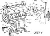
ここで図5〜図5を参照すると、例示する患者看護装置44'は、図5に示すように、基部72と、基部72の上の乳幼児支持プラットフォーム74と、プラットフォーム74の上の乳幼児コンパートメント76とを備えている。例示される患者看護装置44'は、乳幼児保育器、乳幼児輻射保温器、またはそれらの両方として動作可能な乳幼児温度支援装置である。しかし、以下図5〜図25を参照して説明する装置44'の特徴は、病院用ベッド、乳幼児保育器、乳幼児輻射保温器、ストレッチャ、手術台、または、椅子、車椅子、及び、回転マットレス、パーカッションマットレス、低空気損失マットレス、または流動ビーズ表面を含むマットレスまたは治療用表面を有する装置を含む医療環境で患者が安静にする場所となる任意の他の種類の装置等の他の種類の患者治療装置に適用可能である。「マットレス」(単数または複数)という用語は、請求項を含め、本開示で使用される場合、単層マットレス、多層マットレス、ゾーン型マットレス、フォームマットレス、膨張式浮き袋、及び上の文に記載された何らかの治療用表面、及びそれらの組み合わせ及び同等物及び人間を支持するために公知の何らかの他の種類のクッションを含む全ての種類の人間支持要素を対象とするよう意図される。 Referring now to FIGS. 5-5, an exemplary
例示する基部72は、構体またはフレーム78と、フレーム78に接続された1組のキャスタまたは車輪80と、駆動機構(図示せず)を操作して基部72に対するプラットフォーム74の高さを変更するよう介護者によって連結される1組の足踏みペダル82と、不意の衝撃からペダル82を保護する1組のバンパとを有する。プラットフォーム74には、装置44の駆動機構及び他の構成要素を視界から遮る下部部分86が含まれる。また、プラットフォーム74には、装置44の加湿システム(図示せず)の構成要素を支持し、対流式暖房システム(図示せず)の構成要素を支持する上部部分88も含まれる。 The illustrated
乳幼児コンパートメント76には、1対の側壁90と1対の端壁92とが含まれる。1対のアクセスドア94は各側壁90に接続され、側壁90に形成される各アクセスポート(図示せず)を覆う、図5に示す閉位置と、各アクセスポートの覆いをなくし、乳幼児コンパートメント76によって形成される患者空間内の乳幼児に介護者がアクセスできるようにする開位置(図示せず)との間で移動できる。端壁92には各々、1つかそれ以上の線路通過口が含まれ、それを通じて電気線路及び流体管路が患者空間内に通される。側壁90及び端壁92の一部または全ては、図5に示すそれぞれの上昇位置から下降位置(図示せず)に回動可能であり、介護者は乳幼児コンパートメント76内に位置する乳幼児により多くアクセスできるようになる。 The
乳幼児コンパートメント76にはさらに、図5に示すように1対のキャノピー片割れ110を有するキャノピー98が含まれる。装置44'にはオーバヘッドアーム112が含まれるが、これにはキャノピー片割れ110が接続され、キャノピー片割れの下部縁端が側壁90及び端壁92の上部縁端に近接して患者空間をほぼ密閉する、図5に示す下降位置と、患者空間内の乳幼児により多くアクセスできる上昇位置(図示せず)との間で回動移動する。1つかそれ以上の赤外線輻射源(図示せず)がアーム112の下側に設置され、作動すると、輻射熱を患者空間に提供して乳幼児を暖める。装置44'には上部端部を有する柱114が含まれ、そこからオーバヘッドアーム112が片持ち式に延びる。柱114は入れ子式に伸長及び収縮可能であり、キャノピー98、アーム112、及び赤外線輻射源を単一体としてそれぞれ垂直に上昇及び下降させる。装置44'は、柱114を伸長及び収縮するよう動作する駆動機構を有する。 The
また、図5〜図8に示すように、装置44'には、コンピュータ支持具116と、支持具116に結合されたコンピュータ48'とが含まれる。コンピュータ48'は装置44'上で支持される患者及び装置44'自体から患者の診療現場データを受信するよう構成されている。コンピュータ48'はディスプレイ画面118を有し、その上に患者の診療現場データが、以下さらに詳細に説明するように、ユーザからコンピュータ48'が受信した命令に応じて様々な組み合わせで表示される。さらに、コンピュータ48'は、装置44'及びその上で支持される患者に関連する患者の診療現場データを含むデータを病院ネットワークに送信し、ネットワークから、装置44'とほぼ同様の他の装置及びその上で支持される他の装置に関連する患者の診療現場データを含む様々な種類のデータを、ネットワークから検索するよう構成される。従って、装置44'及びその上で支持される患者に関連する患者の診療現場データは、ネットワークからコンピュータ48'によって検索可能な他の種類のデータと共に、診療現場でコンピュータ48'の画面118上で見ることができる。画面118上に表示されるデータ種類を以下図9〜図25を参照して詳細に説明する。しかし、以下説明するデータの追加または代わりとして、図1〜図4を参照して上記で説明した何れかのデータを含む他の種類のデータを画面118上に表示することも本開示の範囲内である。 Also, as shown in FIGS. 5-8, the
例示されるコンピュータ支持具116は、装置44'の他の部分に対してコンピュータ48'の位置を変えることができるよう構成されたアームアッセンブリ(以下「アームアッセンブリ116」と呼ぶ)である。アームアッセンブリ116は、図5及び図7に示すように、第1のアーム120と、第1のUリンク122と、第2のアーム124と、第2のUリンク126とを有する。第1のアーム120は、柱114の下部領域に結合されたカラー部分128と、カラー部分128から外向き及び上向きに角度を付けられた主部分130と、部分130からほぼ水平に外向きに延びる1対のフランジ132とを有する。アーム120は、柱114とカラー部分128との間の相互結合によって形成される第1の垂直軸134の周りに回動可能である。第1のUリンク126は第2の垂直軸136の周りに回動移動するようフランジ132に結合され、第2のアーム124は、第1の水平軸138の周りに回動移動するよう第1のUリンク126に結合されている。第2のUリンク126は第3の垂直軸140の周りに回動移動するよう第2のアーム124の外側端部に結合され、コンピュータ48'は第2の水平軸142の周りに回動移動するよう第2のUリンク126に結合される。 The illustrated
第2のアーム124は、ばねまたはダッシュポット等の釣り合い要素を有する釣り合いアームであり、これはコンピュータ48'の重量と釣り合う十分な釣り合い力を提供するので、コンピュータ48'は、コンピュータ48'とアーム124とが軸138の周りに望ましい位置に調整された後も定位置に保持される。さらに、第2のアーム124には、アーム124が軸138の周りに回動する際地面に対してUリンク126とコンピュータ48'との方向を保持する平行四辺形リンク機構等の方向付け機構が含まれる。例えば、ディスプレイ画面118が、図5(想像線)に示すようにアーム124が下降位置にある時ほぼ垂直の方向にありアーム120と反対の方向を向いており、その後アーム124が軸138の周りで、図5(実線)に示す中間位置等の何らかの他の位置に回動する場合、方向付け機構は、アーム124が下降位置と中間位置との間で移動する際ディスプレイ画面118をアーム120と反対向きのほぼ垂直な方向に保持する。釣り合いアームのさらなる詳細は米国特許第6,012,693号、第5,992,809号、第5,842,672号、第5,826,846号、第5,743,503号及び第5,340,072号に示され説明されており、それら各特許を本出願に援用する。 The
例示の実施形態では、垂直軸134の周りのアーム120の回動移動は柱114に対するアーム120の自由度のみである。その結果、装置44'が設置される床の上のフランジ132及びUリンク122の高さは、アーム120が軸138に沿って回動する際ほぼ同じ高さにある。もちろん、基部72に対するプラットフォーム74の高さを調整すると、床に対するアーム120の高さも調整される。垂直軸136の周りのUリンク122の回動移動はアーム120に対するUリンク122の自由度のみであり、水平軸138の周りのアーム124の回動移動はUリンク122に対する自由度のみである。さらに、垂直軸140の周りのUリンク126の回動移動はアーム124に対するUリンク126の自由度のみであり、水平軸142の周りのコンピュータ48'の回動移動はUリンク126に対するコンピュータ48'の自由度のみである。しかし、コンピュータ支持具116が異なる数の連結要素を有し、隣接する連結要素間の相互接続が多数の自由度(例えば、多数の軸の周りの回動、伸縮運動、または直線伸長/収縮)を有することも本開示の範囲内である。 In the illustrated embodiment, the pivoting movement of the
アームアッセンブリ116の実施形態では、ラグ、ピン、表面等の1つかそれ以上のストッパが要素114、120、122、124、126、48'の間のインターフェースに含まれるか提供され、それぞれ回動軸134、136、138、140、142の周りのこれらの要素の運動の量を制限する。さらに、アームアッセンブリ116の実施形態では、要素114、120、122、124、126、48'の間に配置されたスラスト軸受、ラジアル軸受、平軸受、ブッシング等の様々な減摩構成要素が含まれる。1つの実施形態では、Uリンク126とコンピュータ48'との間、及びUリンク126とアーム124との間に摩擦継ぎ手を設ける。摩擦継ぎ手は、キーボード144上またはディスプレイ画面118に触れることで命令またはデータを入力するユーザが付与する通常の力によってコンピュータ48'がアーム124に対して移動しないような構成である。しかし、摩擦継ぎ手は、キーボード144または画面118上で指令またはデータを入力することに関連する通常の力を越えるしきい値量をコンピュータ48'に印加すると、コンピュータ48'がアーム124に対して位置を変えるような構成である。 In the embodiment of the
装置44'の例示の実施形態では、アームアッセンブリ116及びコンピュータ48'は、コンピュータ48'がプラットフォーム74及び乳幼児コンパートメント76の第1の側面の横に並んで配置される、図6(実線)に示す第1の位置と、コンピュータ48'がプラットフォーム74及び乳幼児コンパートメント76の第2の側面の横に並んで配置される、図6(想像線)に示す第2の位置との間で移動可能である。もちろん、アームアッセンブリ116とコンピュータ48'とは要素120、122、124、126、48'の運動範囲内の無数の位置の何れかに位置決め可能である。また、例示の実施形態では、軸134から軸136までのアーム120の長さは軸134から乳幼児支持プラットフォーム74の側面までの横方向距離より長いことから、コンピュータ48'を配置しうる位置の大部分はプラットフォーム74及び乳幼児コンパートメント76の「底面積」の外側にある。従って、装置44'に隣接した椅子に座ったユーザは椅子に座ったままで使用するのに適した位置にコンピュータ48'を配置することができ、装置44'の横に並んで立つユーザは立ったまま使用するのに適した位置にコンピュータ44'を配置することができる。 In the exemplary embodiment of the
装置44'の他の部分に対してこのような広い範囲の位置にコンピュータ48'を操作できることは、装置と一体化されてはいるが、装置上の位置に固定されているか、または1つまたは2つの自由度内でのみ移動可能といった制限された移動性を有するコンピュータを有する患者支持装置に対する改善である。さらに、コンピュータ48'を装置44'の他の部分から離れて(すなわち、プラットフォーム74及びコンパートメント76の「底面積」の外側に)吊り下げることで、画面118及びキーボード144は、コンピュータ48'及びキーボード144を、例えば、柱114、プラットフォーム74、またはコンパートメント76の上に設置またはそれらによって直接支持するより大型化することができる。 The ability to operate the computer 48 'in such a wide range of positions relative to other parts of the device 44' is either integrated with the device but fixed in position on the device, or one or It is an improvement over a patient support device having a computer with limited mobility such that it can only move within two degrees of freedom. In addition, by suspending the
例示されるコンピュータ48'は、図7に示すように、ディスプレイ画面118及びキーボード144が結合される背面パネルであるプレート146を有する。ブラケット148は背面パネル146の上に設置されUリンク126に接続される。カメラのハウジング150はパネル146の上部部分に接続されディスプレイ画面118の一部の上に張り出す。ビデオカメラ(図示せず)はハウジング150の内部領域に配置され、図8に示すようにハウジング150の前面部分に形成された開口152を通じて画像を受信する。図7及び図8に示すように、電源線、データ線、ビデオ線等のコンピュータ48'に関連する電線はケーブル154に束ねられ、パネル146からアームアッセンブリ116の内部領域を通じてプラットフォーム74の内部領域へと配線される。例示の実施形態ではケーブル154の大部分はアームアッセンブリ116の内部領域に配置されるが、ケーブル154の一部はアームアッセンブリ116の外部に配置されアームアッセンブリ116の継ぎ目に対応する。 The illustrated
装置44'には、図8に概略を示す、装置44'の様々な機能の動作を制御する制御装置156が含まれる。制御装置156によって制御される機能には、輻射保温器の動作、対流式暖房システムの動作、加湿システムの動作、キャノピー98の上昇/下降、及び基部72に対するプラットフォーム74の上昇/下降が含まれる。また、制御装置156は、コンピュータ48'及び多様な他の入力装置から様々な種類のデータを受信する。さらに、制御装置156は様々な種類のデータを、ケーブル154中の適当なデータ線を介してコンピュータ48'に送信し、かつ制御装置156から医療施設のデータポートまたは壁付きコンセント159に延びるデータ線158を介して病院ネットワークに送信する。病院ネットワークからのデータも同様に線路158を通じて制御装置156に伝えられる。すなわち、本開示によれば、装置44'及びコンピュータ48'は患者の診療現場データを含むデータを任意のシステム10、100、200に提供できるだけでなく、データをシステム10、100、200から受信することもできる。換言すれば、装置44'及びコンピュータ48'はシステム10、100、200の加入者34、36の役目を果たすような構成である。 The device 44 'includes a
装置44'には、例えば、患者空間内の気温を感知する気温センサ、乳幼児の体温を感知する乳児体温センサ、患者空間内の湿度を感知する湿度センサ、乳幼児がさらされている騒音レベルを感知する騒音センサ、乳幼児がさらされている光レベルを感知する光センサ、対流式暖房システムのファンが動作する速度を感知するファン速度センサ、装置44'の加熱器のうち関連するものに供給される電流の量を感知する電流センサ、各キャノピー片割れ110がそれぞれ上昇または下降位置にあるかを感知するセンサ、及びオーバヘッドアーム112の上昇を感知するセンサ等の1つかそれ以上の環境センサ及び他の種類のセンサが含まれる。装置44'には、上記記載の様々なセンサを制御装置156と相互接続する適当な電気線路(図示せず)が含まれる。さらに、制御装置156には、装置44'に含まれるセンサによって提供される信号を処理、条件付け、変換、または他の形で操作して使用可能なデータにする電気回路が含まれる。従って、こうした様々な種類のセンサによって提供される信号は、ディスプレイ画面118上で見られ、病院ネットワーク及び/または、上記のように加入者または正規ユーザがデータを検索できる場所である中央データベースに送信される患者の診療現場データの一部を提供する。 The device 44 'includes, for example, an air temperature sensor that senses the temperature in the patient space, an infant body temperature sensor that senses the body temperature of the infant, a humidity sensor that senses the humidity in the patient space, and a noise level to which the infant is exposed. Noise sensors, light sensors that sense the light level to which the infant is exposed, fan speed sensors that sense the speed at which the fan of the convection heating system operates, and heaters of the device 44 ' One or more environmental sensors and other types, such as a current sensor that senses the amount of current, a sensor that senses whether each
装置44'にはさらに、ビデオカメラ160と、カメラ160から制御装置156に延びるビデオデータ線162とが含まれる。カメラ160には、端壁92の1つに接続された下部部分または架台164と、横軸168に沿って回動可能な上部部分166とが含まれる。カメラ160の上部部分166は乳幼児コンパートメント74によって形成される患者空間内に支持される乳幼児に向けられており、乳幼児の画像データを含むカメラ160からのビデオ信号は、線路162を介して制御装置156に伝えられる。また、装置44'は、外部データ線または患者看護モジュール(図示せず)の接続先である複数のコネクタ172を含む接続ポート170を有する。1組の内部データ線174が各コネクタ172から制御装置156に延びる。 The
コネクタ172に接続される外部データ線または患者看護モジュールの中には、心拍数、呼吸数、血液の化学的組成、血圧等の乳幼児の様々な生理学的状態に関する感知データを提供するものがある。また、コネクタ172に接続される他の外部データ線または患者看護モジュールは、栄養補給に関するデータ(例えば、経鼻胃栄養管を介して乳幼児に供給される調合乳の量)、静脈内液体の投与に関するデータ、乳幼児が排出する老廃物に関するデータ、光線療法に関するデータ、心電計(EKG)データ、脳波計(EEG)データ等の患者看護の他の様々な面に関するデータを提供する。従って、接続ポート170によって、装置44'の外部の装置に関連するデータを制御装置156、コンピュータ48'、及び病院ネットワークに伝えることができる。例示される接続ポート170は乳幼児プラットフォーム74の下部部分86の上でアクセス可能であるが、装置44'が乳幼児コンパートメント74内を含む装置上のあらゆる場所に配置された接続ポートを有することが本開示の範囲内である。装置44'は、医療施設の電源コンセント178から標準110V、60Hzの電力を受け取る電源線176を有する。 Some external data lines or patient care modules connected to
制御装置156には、1つかそれ以上のマイクロプロセッサ、マイクロコントローラ、信号処理回路、出力調整回路、メモリ回路、I/O回路、等が含まれる。ある実施形態では、コンピュータ48'が、固有のマイクロプロセッサまたはマイクロコントローラ及び適当な通信プロトコルによって制御装置156の回路と通信する関連回路を有するものもある。他の実施形態では、コンピュータ48'は制御装置156の回路によって制御される。 The
例示されるコンピュータ48'には、図8に示すバーコード読み取り装置178が含まれ、それにトークンを提示してトークンの所有者がある情報へのアクセスを得られるようにする。本開示によれば、「低アクセス」トークン180は装置44'上で支援されている乳幼児の親族に与えられ、「高アクセス」トークン182は医師、看護師、及び他の介護者に与えられる。各トークン180、182には、読み取り装置178によって読み取られるバーコード184が含まれる。トークン180に関連するバーコード184はトークン182に関連するバーコード184と異なっているので、コンピュータ48'は、トークン180、182のどちらが読み取り装置178に提示されたかを識別できる。トークン182が読み取り装置178に提示された場合、トークン182の所有者はコンピュータ48'を介して利用可能な全ての情報へアクセスすることができるが、トークン180が読み取り装置178に提示された場合、トークン180の所有者はコンピュータ48'を介して制限された量の情報にだけアクセスできる。中間レベルのアクセス(すなわち、トークン180によってアクセスできる情報よりは多いが、トークン182によってアクセスできる情報よりは少ない情報へのアクセス)を許可するトークンも本開示の範囲内である。 The illustrated computer 48 'includes a
例示されるトークン180、182は、バーコード184が上に印刷されるか、または、例えばラベルにより他の方法で貼付されたカードである。コンピュータ48'が、磁気ストリップを保持するカード、コード化無線周波(RF)信号を送信するトークン、近接カード、及び赤外線エネルギーを送信または反射するトークン等の他の種類の関連するトークン用の、磁気ストリップ読み取り装置、RF受信機、近接カード読み取り装置、及び赤外線エネルギー受信機等の、バーコード読み取り装置以外の読み取り装置を有することも本開示の範囲内である。また、ユーザが、ユーザIDとパスワードとをコンピュータ48'のディスプレイ画面118上に現れる適当なフィールドに入力することによって情報へのアクセスを得ることも本開示の範囲内である。 The illustrated
以下の説明では、様々なデータまたは情報が「ディスプレイ画面118上に現れる」または「画面118上に表示される」(あるいは画面118の一部またはウィンドウ上に「現れる」または「表示される」)等の記載または同様の記載がある場合、制御装置156の回路及び/またはコンピュータ48'の回路及び/または病院ネットワークのコンピュータ装置中の回路が1つかそれ以上のそれぞれのコンピュータプログラムを実行してデータまたは情報を画面118上に表していると理解されたい。さらに、コンピュータ48'がある機能を達成するため「ソフトウェアを実行する」または「ソフトウェアを走らせる」等の記載または同様の記載がある場合、こうした記載は、病院ネットワークの1つかそれ以上のコンピュータ装置がソフトウェアを実行または走らせている場合、制御装置156がソフトウェアを実行または走らせている場合、及びコンピュータ48'自体がソフトウェアを実行または走らせている場合の実施形態を対象にするよう意図される。 In the following description, various data or information “appears on
以下の説明では、アイコンまたはボタンが「選択される」または「反転表示される」またはユーザがボタンまたはアイコンを「選択する」または「反転表示する」等の記載または同様の記載がある場合、本開示は、コンピュータ画面上に現れるアイコンまたはボタン等の図形または文字画像を選択または反転表示する全ての方法を対象にすることを意図していると理解されたい。こうした図形または文字画像の選択は、例えば、コンピュータマウスを動かしてカーソルを選択すべき画像の部分に重ねてからコンピュータマウス上のボタンをクリック(またはダブルクリック)する、コンピュータキーボード上の左、右、上、及び下矢印キーを使用して様々な画像を反転表示し、望ましい画像が反転表示されたらキーボードの「エンター」キーを押す、コンピュータキーボード上の「タブ」キーを使用して様々な画像を反転表示し、望ましい画像が反転表示されたらキーボードの「エンター」キーを押す、望ましい画像を有する画面の部分の上で光ペンでコンピュータ画面に触れる、音声制御ソフトウェアを使用して望ましい画像を口頭で選択する、及びコンピュータ画面がタッチスクリーンである場合、タッチスクリーンの望ましい画像を有する部分に触れる、といった方法で達成すればよい。 In the following description, if the icon or button is “selected” or “highlighted” or the user “selects” or “highlighted” the button or icon, or the like, It should be understood that the disclosure is intended to cover all methods of selecting or inverting a graphic or character image such as an icon or button that appears on a computer screen. These graphic or character images can be selected, for example, by moving the computer mouse over the part of the image to be selected and then clicking (or double-clicking) a button on the computer mouse. Use the Up and Down arrow keys to highlight various images, and when the desired image is highlighted, press the “Enter” key on the keyboard. Use the “Tab” key on the computer keyboard to view the various images. Highlight the desired image, press the “Enter” key on the keyboard, touch the computer screen with a light pen over the part of the screen that has the desired image, and use the voice control software to verbally display the desired image If selected and the computer screen is a touch screen, the touch screen Touching portion having a desired image may be achieved in such a way.
トークン180、182の何れかが読み取り装置178に提示される前か、またはトークン180、182の1つが読み取り装置178に提示されたが何らかの命令がコンピュータ48'上で入力されることなく所定の期間が経過した場合、例えば、図9に示すようなデフォルト画面186がディスプレイ画面118上に現れる。画面186は「分割画面」ディスプレイとして現れ、様々な種類のデータが分割画面の関連するウィンドウ内に現れる。 Either one of
患者の個人別情報が、図9に示すように画面186の左上領域の個人別情報ウィンドウ188内に示される。個人別情報には、患者の氏名、患者が割り当てられたベッド番号、警報インジケータ(点滅または他の方法で状態が変化し、警報状態が感知されたことを示す)、患者の生後日数、患者の最近の体重とその最近の体重を測定した日付、患者の出生時体重、患者に割り当てられた医師、患者に割り当てられた看護師が含まれる。ウィンドウ188の下は画像ウィンドウ190であり、カメラ160によって取り込まれた患者のビデオ画像をリアルタイムで表示する。ウィンドウ190の下は環境ウィンドウ192であり、コンパートメント76内の気温、患者の体温、コンパートメント76内の相対湿度、及びコンパートメント76内のパーセント酸素濃度等の環境データを表示する。ウィンドウ192の下は生命徴候データウィンドウ194であり、吸気酸素成分(FIO2)、呼吸数(RR)、最高吸気圧力(PIP)、持続性気道陽圧(CPAP)、吸/呼気相比(I:E:)、及び呼吸終末陽圧(PEEP)等の生命徴候データを表示する。 Individual patient information is shown in the
画面86の上中央領域には、生命徴候グラフウィンドウ196が画面186上に表示される。ウィンドウ196は患者の心拍数、動脈血圧、静脈血圧、及び呼吸数のグラフ表示を有する。患者のパルス酸素飽和度(SpO2)もウィンドウ196内に記載される。ウィンドウ196の下は空白ウィンドウ198である。ウィンドウ198の下は、ベッドアイコン212、アームアイコン214、角度アイコン216、負符号アイコン218、正符号アイコン220、及びメッセージアイコン222を有するコントロールバー210である。ユーザがアイコン212を選択すると、アイコン212が反転表示され、その後負符号アイコン218または正符号アイコン220の何れかを押すと、プラットフォーム74(及びプラットフォーム74によって支持される構成要素)が基部72に対してそれぞれ下降または上昇する。ユーザがアイコン214を選択すると、アイコン214が反転表示され、その後負符号アイコン218または正符号アイコン220の何れかを押すと、柱114はプラットフォーム74に対してそれぞれ収縮または伸長し、アーム112、キャノピー98、輻射保温器、及びそれらの何れかに接続された何らかの他の構成要素をそれぞれ下向きまたは上向きに移動させる。ユーザがアイコン216を選択してから負符号アイコン218または正符号アイコン220の何れかを押すと、乳幼児プラットフォーム74によって支持されるマットレスが、装置44'の傾斜機構と関連することによって、それぞれトレンデレンブルク体位または逆トレンデレンブルク体位に向かい移動する。 A vital
画面186の右手側には(画面の上から下に)ユーザ氏名ウィンドウ224、時刻ウィンドウ226、主ディスプレイコントロールウィンドウ228、第2画像ウィンドウ230、及びコントロールボタンウィンドウ232が表示される。トークン180、182は読み取り装置178に提示されていないので、ユーザ氏名ウィンドウ224及びコントロールボタンウィンドウ232は空白である。ある実施形態では、カメラ160等の2つのカメラがコンパートメント76に設置されることがある。2つのカメラを有するこうした実施形態では、第2画像ウィンドウ230は一方のカメラからの画像を表示し、第1画像ウィンドウ190はもう一方のカメラからの画像を表示する。例示の実施形態では、ウィンドウ190、230は、ユーザ入力に応じて、患者の重複した画像を表示することもある。すなわち、ユーザ入力に応じて、ウィンドウ190、230の1つに他の種類のデータを表示することがあってもよく、従ってカメラ160からの患者の画像もウィンドウ190、230のもう一方に表示することができる。 On the right hand side of the screen 186 (from the top to the bottom of the screen), a
ウィンドウ228は、「モード」ボタン234、「コンテント」ボタン236、「シングル」ボタン238及び「マルチ」ボタン240を有する。ユーザがボタン234を選択または反転表示すると、ユーザはボタン238またはボタン240の何れかを選択する選択肢を有する。ユーザが初めにボタン234を選択した後ボタン238を選択すると、例えば図9に示すように、コンピュータ48'の接続された特定の装置44'の患者に関連するデータがディスプレイ画面118上に現れる。ユーザが初めにボタン234を選択した後ボタン240を選択すると、以下図25に関連してさらに詳細に説明するように、装置44'を含む多数の患者支援装置44に関連するデータがディスプレイ画面118上に現れる。ユーザがボタン236を選択すると、ユーザは、データの種類の変更、データのフォーマット、及びユーザが現在見ている画面上に現れるデータを含むウィンドウの配置という選択肢を有する。例えば、ユーザがデフォルト画面186を見ながらボタン236を選択すると、ユーザは望ましい方法で画面186上に現れる情報を変更できる。従って、ユーザが本出願で説明する各画面上に現れるデータをカスタマイズすることは本開示の範囲内である。コンピュータ48'はカスタマイズされた画面をトークン180、182を所持する各ユーザに関連付けるので、画面は自分のトークンを読み取り装置178に提示した特定のユーザに合わせて自動的に設定される。 The
親族等の人物が「低アクセス」トークン180をコンピュータ48'の読み取り装置178に提示すると、例えば図10に示すように、低アクセスホーム画面242がコンピュータ48'のディスプレイ画面118上に現れる。画面242には、画面186の場合と同様ウィンドウ188、190、192、194、196、198、226が含まれるが、各ウィンドウ中のデータは、データが変更されるに連れてほぼリアルタイムで更新される。病院ネットワーク、コンピュータ48'及び/または制御装置156は、カード180上の特定のバーコードに関連するユーザ識別情報を格納している。従って、カード180が割り当てられたユーザの氏名がウィンドウ224内に現れる。例示される例では、それぞれウィンドウ188、224に現れるデータが示す通り、ケヴィン・ジョーンズ(Kevin Jones)は装置44'上で支援される患者の氏名であり、トークン180の所有者はケヴィンの母親サラ・ジョーンズ(Sarah Jones)である。 When a relative or other person presents the “low access”
画面242のウィンドウ232には、記録ボタン244、設定ボタン246、ビデオボタン248、ビデオ会議ボタン250、Eメールボタン252、ウェブボタン254、ログアウトボタン256、及び主画面ボタン258が含まれる。ユーザがボタン244を選択すると、ボタン244が選択された時にウィンドウ196に現れていたグラフと関連情報が、病院ネットワーク、制御装置156、或いはコンピュータ48'に接続されたプリンタ(図示せず)によって印刷出力される。ユーザがボタン246を選択すると、ユーザは格納及び/またはEメールに添付する画像及び/またはデータを選択できる。例えば、ユーザは、ウィンドウ190に現れる乳幼児の患者の画像を取り込み、その画像を別の親族等の受信者にEメールで送るというオプションを有する。ユーザがボタン248を選択すると、コンピュータ48'は、ユーザがコンピュータ48'を介してデータにアクセスするトークンを有する任意の他の人物にビデオメッセージを残せるようにするソフトウェアプログラムを実行する。コンピュータ48'のハウジング150内に配置されたカメラはビデオメッセージを残すユーザのビデオ画像を取り込み、コンピュータ48'のハウジング150内に配置されるかまたはマイクロホンジャック260(図8)に接続されるマイクロホンはメッセージの音声部分を取り込む。コンピュータ48'を何らかの公知のビデオメッセージングソフトウェアによってプログラムすることは本開示の範囲内である。 The
ユーザがボタン250を選択すると、コンピュータ48'はユーザがビデオ会議を設定またはそれに参加できるようにするソフトウェアプログラムを実行する。コンピュータ48'を何らかの公知のビデオ会議ソフトウェアによってプログラムすることは本開示の範囲内である。ユーザがメッセージアイコン222を選択すると、例えば図11に示すように、メッセージ画面260がコンピュータ48'のディスプレイ画面118上に現れ、受信メッセージ表262と送信メッセージ表264とがウィンドウ198内に現れる。表262は、ユーザ宛に送信されたがまだユーザが見ていないEメールまたはビデオメッセージがあればそれに関する1行またはそれ以上の情報を有する。表262はユーザが送信したがまだユーザが消去または削除していないビデオメッセージのEメールがあればそれに関する1行またはそれ以上の情報を有する。 When the user selects
表262、264の各項目は、ビデオアイコン266またはEメールアイコン268のいずれかを有し、関連するメッセージがそれぞれビデオメッセージであるかまたはEメールであるかを示す。さらに、表262の各項目はユーザが関連するビデオメッセージを再生するために選択する再生ボタン267を有し、表264の各項目はユーザが表264から送信メッセージを削除するために選択する消去ボタン269を有する。また、表262の各項目はメッセージを送信した人物の氏名、メッセージの件名、メッセージがユーザ宛に送信された日付、及びメッセージがユーザ宛に送信された時刻を有する。同様に、表264の各項目は、ユーザがメッセージを送信した宛先の人物の氏名、メッセージの件名、ユーザがメッセージを送信した日付、ユーザがメッセージを送信した時刻を有する。 Each entry in the tables 262, 264 has either a
ウィンドウ198の表262、264の右側にスクロールアイコン270が設けてあるので、表262、264がウィンドウ198内に同時に表示できるより多い項目を有する場合、ユーザは表262、264の項目をスクロールできる。画面260のウィンドウ198の下端には、受信ボタン272、送信ボタン274、及び新規ボタン276が存在する。ユーザがウィンドウ198の上部に受信メッセージ表262を配置したい場合、ユーザは受信ボタン272を選択し、ユーザがウィンドウ198の上部に送信メッセージ表264を配置したい場合、ユーザは送信ボタン274を選択する。ユーザが新しく受信したメッセージだけを見たい場合、ユーザはボタン276を選択する。 A
ユーザがメッセージアイコン222を選択した結果、ウィンドウ232内の記録、設定、及びビデオボタン244、246、248は、図11及び図12に示すように、画面260上で再生ボタン278、停止ボタン280、及び巻き戻しボタン282に置換される。ユーザが表262内に現れる再生ボタン267の1つを反転表示してからウィンドウ232内に現れる再生ボタン278を選択すると、例えば図12に示すように、コンピュータ48'は反転表示された再生ボタン267に関連する項目のビデオメッセージを再生する。選択されたビデオメッセージが再生されている間、コンピュータ48'のメモリ中に格納されたビデオデータがウィンドウ230内に表示され、音声データがコンピュータ48'に収容または接続されたスピーカ(図示せず)或いは、コンピュータ48'のヘッドホンジャック284(図8)に接続されたヘッドホン(図示せず)の何れかに提供される。ユーザは、音量つまみ285(図8)を動かすか、またはコントロールバー210のアイコン218、220を選択することによって音声データの音量を調整できる。ユーザがビデオメッセージの再生を停止したい場合、ユーザはボタン280を選択する。ユーザがビデオメッセージを巻き戻したい場合、ユーザはボタン282を選択する。 As a result of the user selecting the
ユーザが画面242、260のウィンドウ232内に現れるEメールボタン252を選択すると、例えば図13に示すように、Eメール画面286がコンピュータ48'のディスプレイ画面118上に現れる。Eメール画面286は、画面242、260の生命徴候ウィンドウ196の代わりとなるEメールウィンドウ296を有する。しかし、画像ウィンドウ190は、グラフ形式の代わりに表形式の生命徴候情報を含む補助生命徴候ウィンドウ290によって置換されるので、ユーザは引き続き画面286上でほぼリアルタイムで生命徴候データを見ることができる。例示の実施形態では、ウィンドウ190をウィンドウ290によって置換するため、カメラ160からの画像は画面286上のウィンドウ230内に示される。 When the user selects the
Eメールウィンドウ296は、Eメールの作成に関連するいくつかの機能をユーザが行えるようにする様々なアイコンを含む指令バー288を有する。例示される例では、指令バー288には、送る、切り取り、コピー、貼り付け、元に戻す、文法チェック、スペルチェック、及び添付といったアイコンが含まれる。こうした各アイコンに関連する機能は公知である。例えば、添付アイコンを使用して、ユーザは、ユーザが上記で説明したように設定ボタン246を使用してコンピュータ48'のメモリに格納した何らかのデータ及び/または画像を添付する選択肢を有する。また、ウィンドウ296には「宛先」ダイアログボックス292と「CC」ダイアログボックス294が含まれ、そこにユーザはユーザが作成されたEメールの受信者の氏名を入力する。ウィンドウ296はさらに、ユーザがEメールの件名を入力する「件名」ダイアログボックス298と、ユーザが送信するEメールメッセージを入力するメッセージダイアログボックス300とを有する。 The
ウィンドウ296はさらに、例えば、フォントダイアログボックス(関連するドロップダウンメニュー矢印を有する)、テキストサイズダイアログボックス(関連するドロップダウンメニュー矢印を有する)、テキスト字下げアイコン、太字アイコン、斜体アイコン、下線アイコン、テキスト色アイコン、テキスト行揃えアイコン、箇条書きアイコン等のいくつかのアイコン及びダイアログボックスが含まれる。このそれぞれのテキストフォーマットアイコンに関連する機能は公知である。指令バー288とテキストフォーマットバー310とをカスタマイズして、選択されると関連する機能を行うアイコンを含むようにすることは、本開示の範囲内である。こうしたカスタマイズ能力は、ノベルグループワイズ(Novell Groupwise)Eメールソフトウェア及びロータスノーツ(Lotus Notes)Eメールソフトウェア等の市販のEメールソフトウェアパッケージに含まれる。 The
例えば、ユーザが画面242、260、286のウィンドウ232に現れるウェブボタン254を選択すると、例えば、装置44'が設置された病院をホストとするウェブサイトまたは装置44'の製造業者をホストとするウェブサイト等の指定されたウェブサイトのホームページ(図示せず)がウィンドウ198内に現れる。また、コンピュータ48'の画面118上に現れる多数のウィンドウに重なるウェブページウィンドウが表示されることもある。コンピュータ48'は、(ワールドワイドウェブとしても公知の)インターネットにユーザが接続しそれを見て回ることを可能にし、ボタン254が選択されると起動される、ネットスケープナビゲータ(NETSCAPE NAVIGATOR(登録商標))ソフトウェアまたはマイクロソフトエクスプローラ(MICROSOFT EXPLORER(登録商標))ソフトウェア等の適当なウェブブラウザソフトウェアによってプログラムされる。ユーザが主画面ボタン258を選択すると、コンピュータ48'は図10にその例を示す画面242によって応答する。ユーザがログアウトボタン256を選択すると、コンピュータ48'は図9にその例を示す画面186によって応答する。 For example, if the user selects the
医師または看護師等の人物が「高アクセス」トークン182をコンピュータ48'の読み取り装置178に提示すると、例えば図14に示すように、高アクセスホーム画面312がコンピュータ48'のディスプレイ画面118上に現れる。画面312には、画面186の場合と同様ウィンドウ188、190、192、194、196、198、226が含まれるが、各ウィンドウ中のデータは、データが変更されるに連れてほぼリアルタイムで更新される。病院ネットワーク、コンピュータ48'及び/または制御装置156は、カード182上の特定のバーコード184に関連するユーザ識別情報を格納している。従って、カード182が割り当てられたユーザの氏名がウィンドウ224内に現れる。例示される例では、ウィンドウ224内に現れるデータが示す通り、トークン182の所有者はケヴィン・ジョーンズの担当医であるジェーン・スマイス(Jane Smythe)医師である。 When a person such as a doctor or nurse presents a “high access” token 182 to the
画面242のウィンドウ232の場合と同様、画面312のウィンドウ232には、記録ボタン244、設定ボタン246、ビデオボタン248、ビデオ会議ボタン250、Eメールボタン252、ウェブボタン254、ログアウトボタン256、及び主画面ボタン258が含まれる。しかし、図14に示すように、画面312のウィンドウ232にはさらに、販売/サービスボタン314、研究ボタン316、供給品ボタン318、ポンプ/流体ボタン320、評価ボタン322、スケジュールボタン324、放射線医学ボタン326、薬物療法ボタン328、教育ボタン330、検査室ボタン332、及び通話ボタン334が含まれる。画面312及び高アクセスホーム画面312からアクセスできる任意の他の画面上でボタン244、246、248、252、254、256、258を選択すると、上記で図10〜図13を参照して説明したのとほぼ同様の画面及びデータがコンピュータ48'のディスプレイ画面118上に現れる。また、画面312はアイコン212、214、216、218、220、222を有し、それを選択すると、上記で図9〜図13を参照して説明した対応するボタン各々の場合と同様のデータが検索され、かつ/または同様の機能が行われるが、アイコン222が選択されるとき画面312のウィンドウ198内に現れるメッセージ表には、トークン180の所有者ではなくトークン182の所有者が受信または送信したメッセージに対応する項目が含まれる。 As with the
ユーザがビデオ会議アイコン250を選択すると、例えば図15に示すように、ビデオ会議コントロール画面336がコンピュータ48'のディスプレイ画面118上に現れる。画面336のウィンドウ198は、「患者ベッド選択」ボタン340、「URL/IPアドレス入力」ボタン342、及び「接続」ボタン344を含むビデオ会議コントロールパネル338を有する。ユーザが画面336上のボタン340を選択した後、ユーザはどの装置44がビデオ会議上で利用可能な関連画像を有するかを識別することができる。この例では、デフォルトの患者ベッドは装置44'である。しかし、ユーザは、病院ネットワークに接続された任意の患者ベッド(すなわち、装置44)を選択する選択肢を有する。ユーザがボタン342を選択した後、ユーザはインターネットアドレス(単数または複数)によってビデオ会議の他の参加者(単数または複数)を識別できる。ユーザがビデオ会議に含まれる患者ベッドと受信者を識別した後、ユーザはボタン344を選択して受信者に接続する。従って、本開示によれば、ビデオ会議はワールドワイドウェブによって達成される。しかし、LAN、WAN、または直接回線通信を介したビデオ会議を可能にするソフトウェアを含む任意の公知のビデオ会議ソフトウェアによってコンピュータ48'をプログラムすることも本開示の範囲内である。 When the user selects the
ユーザがボタン250を選択し、それによって画面336がコンピュータ48'のディスプレイ画面118上に現れるようにすると、記録、設定、及びビデオボタン244、246、248はカメラコントロールバー346によって置換されるが、このカメラコントロールバー346には、例示の実施形態では、ズームアウトボタン348、ズームインボタン350、及びカメラ切り換えボタン352が含まれる。コンピュータ48'のハウジング150内のカメラとコンパートメント76に設置されたカメラとを含む、装置44'の任意の1つかそれ以上のカメラを電動式にして、カメラコントロールバー346が、カメラを左右にパンし、カメラを上下に移動させ、ビデオカメラに関連する輝度または色相または何らかの他のパラメータを制御するボタンを含むことは本開示の範囲内である。 When the user selects
ボタン352を選択することによって、ユーザはウィンドウ230内に現れる画像を切り換えることができるが、この画像は通常、ビデオ会議の他の参加者の1人のカメラからの画像である。従って、ボタン352を連続して選択することによって、ユーザは、ビデオ会議の他の参加者に関連する各カメラに関連する画像を続けて見ることができ、カメラ160に関連しかつコンピュータ48'のハウジング150内のカメラに関連する画像を見ることもできる。ボタン348を選択することによって、ユーザはウィンドウ230内に現れる画像にズームインすることができ、ボタン350を選択することによって、ユーザはウィンドウ内に現れる画像からズームアウトすることができる。従って、ウィンドウ230内に現れる画像がビデオ会議の他の参加者の1人に関連するカメラからの画像である場合、コンピュータ48'は、他の参加者のカメラがコンピュータ48'が生成する信号によって制御されるよう構成されていると想定して、その他の参加者のカメラを制御する適当な信号を生成する。 By selecting
ある実施形態では、ユーザが、ビデオ会議の他の参加者に送信される画像を制御するものもある。こうした実施形態では、ビデオ会議の他の参加者に利用可能な画像がウィンドウ230に示される。また、こうした実施形態では、ボタン352を連続して選択すると、ウィンドウ230内に示される画像をカメラ160に関連する画像とハウジング150内のカメラ(及び装置44'の任意の他のカメラ)に関連する画像との間で切り換えることができ、さらに、ボタン348、350を選択してウィンドウ230内に現れる画像にそれぞれズームアウトまたはズームインすることができる。ビデオ会議の間、音量つまみ285、またはアイコン218、220を使用して会議の音声部分の音量を調節する。 In some embodiments, the user controls the images that are sent to other participants in the video conference. In these embodiments,
ユーザがウィンドウ232内の販売/サービスボタン314を選択すると、例えば図16に示すように、販売/サービス画面354がコンピュータ48'のディスプレイ画面118上に現れる。画面354のウィンドウ198はサービス連絡先表356と販売連絡先表358とを有する。表356には、装置44'に関連する病院に割り当てられた顧客サービス担当者または技術者の写真、その顧客サービス担当者または技術者の氏名、及びその顧客サービス担当者または技術者の連絡先電話番号等のサービス連絡先情報が含まれる。さらに、表356はサービスアイコン360を有し、それを選択すると、Eメール画面286がディスプレイ118上に現れるが、そこでは顧客サービス担当者または技術者のEメールアドレスがすでにダイアログボックス292に入力されているので、ユーザはEメールメッセージを作成、送信してサービス情報を要求したり、顧客サービス担当者または技術者の訪問を要求したりすることができる。 When the user selects the sales /
表358には、装置44'に関連する病院に割り当てられた販売担当者の写真、その販売担当者の氏名、及びその販売担当者の連絡先電話番号等の販売連絡先情報が含まれる。さらに、表358は販売アイコン362を有し、それを選択すると、Eメール画面286がディスプレイ118上に現れるが、そこでは販売担当者のEメールアドレスがすでにダイアログボックス292に入力されているので、ユーザはEメールメッセージを作成、送信して販売情報を要求したり、販売担当者の訪問を要求したりすることができる。また、表358は製造業者ウェブリンクアイコン364を有し、それを選択すると、装置44'の製造業者のウェブサイトのホームページがコンピュータ48'のディスプレイ画面118上に現れる。例示される例では、ボタン314及びアイコン364の上には各々「ヒル−ロム(Hill−Rom)」が表示されており、ヒル−ロムが装置44'の製造業者であることを示している。また、ボタン314の上には「販売/サービス」または「製造業者連絡先」等の他のテキストが表示されていることもあり、アイコン354は、例えば「製造業者ホームページ」または「製造業者ウェブサイトへのリンク」等の他のテキストが表示されていることもある。さらに、表358はヘルプアイコン366を有し、それが選択されると、ユーザをコンピュータ48'のヘルププログラムにリンクする。ヘルププログラムを使用して、ユーザは装置44'の動作に関する照会を入力または情報を検索することができる。 Table 358 includes sales contact information such as a picture of the salesperson assigned to the hospital associated with device 44 ', the name of the salesperson, and the contact phone number of the salesperson. In addition, table 358 has a
ユーザが研究ボタン316を選択すると、例えば図17に示すように、研究画面368がコンピュータ48'のディスプレイ画面118上に現れる。例示される画面368には、相関パラメータウィンドウ370、第1の研究データウィンドウ376、及び第2の研究データウィンドウ378が含まれる。ウィンドウ370、376、378は、ボタン316が選択される前にディスプレイ画面118上に表示されていたいくつかのウィンドウまたはそれらの一部に取って代わる。例えば、生命徴候グラフウィンドウ196はウィンドウ370、376、378に置き換えられる。しかし、画像ウィンドウ190は、グラフ形式の代わりに表形式の生命徴候を含む補助生命徴候ウィンドウ290によって置換されるので、ユーザは引き続き画面386上でほぼリアルタイムで生命徴候データを見ることができる。 When the user selects the
システム10、100、200を含む、本出願で説明した何らかの患者の診療現場データ管理システムの何らかの部分からアクセス可能な何らかのデータに分類、同化、マイニング、グラフ化、作表、相関等の処理を行い、研究画面368上でユーザに提示することは本開示の範囲内である。例示される例では、ウィンドウ370には、各々メニュー矢印374を有する6つのパラメータ入力アイコン372の組み合わせが含まれる。相関させるパラメータを選択するため、ユーザはそれぞれのアイコン372の矢印374を選択して、関連するパラメータ選択メニューを画面368上に表示する。次にユーザはパラメータの1つをパラメータ選択のメニューから選択する。ユーザが望ましい数のパラメータ(例示される例では6まで)を選択するまでこのパラメータの選択を繰り返す。 Perform classification, assimilation, mining, graphing, tabulation, correlation, etc. into some data accessible from some part of any patient point of care data management system described in this application, including
選択されたパラメータに基づいて、装置44'をその一部とするネットワークまたはシステムに含まれるデータベースからいくつかのデータがコンピュータ48'に提供され、画面368のウィンドウ376、378内に表示される。図17に示すように、ウィンドウ376は第1の研究結果アイコン380を有し、ウィンドウ378は第2の研究結果アイコン382を有する。各アイコン380、382は各々それぞれに関連付けられた「次へ」矢印384を有する。アイコン380、382の何れかを連続して選択することによって、ユーザは利用可能な研究データをスクロールできる。代替実施形態では、アイコン380、382を選択すると、それぞれのウィンドウ376、378内に利用可能な研究データ選択のドロップダウンメニューが現れるので、ユーザはメニューから、対応するウィンドウ376、378内に表示すべき望ましい研究データを選択することができる。 Based on the selected parameters, some data is provided to the
図17の例示される例では、アイコン380内に「神経状態」と表示され、関連する棒グラフ386(例えば、ブラゼルトン評価)がウィンドウ376内に現れる。また、例示される例では、アイコン382内に「母年齢」と表示され、関連する円グラフ388がウィンドウ378内に現れる。ある実施形態では、ウィンドウ376、378内に表示される研究データが、システム10、100、200が現在データを受け取っている様々な患者のリアルタイムの患者の診療現場データに基づいていることがある。別の実施形態では、ウィンドウ376、378内に示されるデータは、システム10、100、200が過去にデータを受信した様々な患者の履歴患者の診療現場データに基づいている。また別の実施形態では、ウィンドウ376、378内に現れる研究データは、何らかの他の情報源から受信したかまたはシステム10、100、200に手動で入力されるデータに基づいている。コンピュータ48'を介してアクセス可能な研究データが何らかの上記で説明されたデータの情報源からのデータの集約または組み合わせに基づくことは本開示の範囲内である。 In the illustrated example of FIG. 17, “Neural status” is displayed in
ユーザがメニュー232から供給品アイコン318を選択すると、例えば図18に示すように、供給品画面390がコンピュータ48'のディスプレイ画面118上に現れる。例示される画面390には供給品ワークシートウィンドウ392と供給品リストウィンドウ394とが含まれる。ウィンドウ392、394は、ボタン318を選択する前にディスプレイ画面118上に表示されていたウィンドウ196、198に取って代わる。その結果、生命徴候グラフウィンドウ196からのデータは、ウィンドウ190を置換する補助生命徴候ウィンドウ290に表形式でほぼリアルタイムで示される。さらに、カメラ160からの画像は、ウィンドウ190をウィンドウ290によって置換したことにより、画面390上のウィンドウ230内に示される。 When the user selects the
画面390のウィンドウ394は、乳幼児に利用可能及び/または保管コンパートメントまたは装置44'の近くで利用可能な供給品のリストを有する。ウィンドウ394内に現れる供給品のリストには、関連供給品の名称を示す品目縦列396と、利用可能な品目の単位数を示す「在庫」縦列398と、該当する場合単位の種類(例えば、バッグ、組、包、瓶)を示す単位縦列400とが含まれる。例示される例では、ウィンドウ394内の供給品のリストには、ブドウ糖添加生理食塩水(D5W 500CC溶液)4バッグ、ER 500CC静注液8バッグ、ECGパッド2組、紙おむつ13個、テープ2巻、25グラムIV4個、温度パッチ1個、毛布3個、スポンジ5包、シーツ3枚、カテーテル25 1個、ストッキネット3個、及び追加紙おむつ13個が含まれる。患者の看護のために使用される任意の種類の供給品を供給品のリストに含むことは本開示の範囲内である。
ウィンドウ394は、各々図18に示すようにウィンドウ394内に記載されたそれぞれの供給品品目の横に配置された複数の編集アイコン410を有する。また、ウィンドウ394は、追加アイコン414、使用アイコン416、削除アイコン418、及び注文アイコン420を含む操作アイコン縦列412を有する。ユーザが特定の供給品項目を選択した後、関連するアイコン410を選択することによって、ユーザはアイコン414、416、418、420のうち適当な1つを選択して望ましい操作を行うことができる。例えば、ユーザが選択された項目の品目を1つかそれ以上使用しようとする場合、ユーザはアイコン414を選択して品目を1つかそれ以上選択した項目に追加し、ユーザはアイコン416を選択する。さらに、ユーザが選択した項目から品目を1つかそれ以上削除したいが、他に削除する品目を使用する予定がない場合、ユーザはアイコン418を選択する。アイコン416を選択することによって装置44'に関連するシステムは選択した品目を使用したことに対して患者に課金し、一方アイコン418が選択されると、装置44'に関連するシステムは患者に課金しない。アイコン418の選択は、例えば、選択した供給品を他の患者が使用したり、病院の供給品室に返却したりする場合に対応する。アイコン420を選択すると、ユーザはより多くの選択された品目を病院の供給品室から注文できる。 The
アイコン414、416、418、420の1つが選択される時はいつでも、選択されたアイコン414、416、418、420の1つの横の数量縦列内に数量ダイアログボックス(図示せず)が現れる。ユーザは、状況に応じて、ユーザが追加、使用、削除、または注文したい選択した供給品の単位数量を入力する。ユーザがアイコン414またはアイコン420の何れかを選択する前に編集アイコン410がどれも選択されていなければ、アイコン414、420の何れかを選択することによってウィンドウ392はアクティブになり、ユーザは状況に応じてウィンドウ394に追加または注文すべき供給品に関する情報を入力できる。ウィンドウ394はさらに「保存して終了」アイコン424を有し、ユーザはウィンドウ394を編集し、かつ/またはウィンドウ392に情報を入力した後でこれを選択する。アイコン424を選択すると、縦列396、398、400内に現れる情報は自動的に更新される。ウィンドウ394は「取り消し」アイコン426を有し、ユーザはウィンドウ392、394に対して行った何らかの変更を取り消したい場合これを選択する。 Whenever one of the
ユーザがウィンドウ232内のボタン320を選択すると、例えば図19に示すように、ポンプ/流体画面428がコンピュータ48'のディスプレイ画面118上に現れる。画面428のウィンドウ198は摂取物表430と排出物表432とを有する。摂取物表430は患者に注入、ポンピング、または他の方法で患者に供給される流体に関する様々な種類の情報を記載する。例示される表430中の各項目は、関連する流体を患者に投与するポンプの番号、関連する流体のバッグの番号、関連するバッグの内容、流体を投与する患者の部位、流体を患者に投与する速度(立方センチメートル/時)、当日中に患者に供給される流体の量、現在のシフト中に患者に供給される流体の量、等の情報を提供する。さらに、表430は「合計」横行434を有し、そこには全ての流体が患者に投与される速度の合計、当日中に患者に供給される全ての流体の量の合計、及び現在のシフト中に患者に供給される全ての流体の量の合計が示される。排出物表432は、様々な種類の流体が患者から排出される容量速度(立方センチメートル/時)を記載する。また、表432は患者から排出される流体の合計を記載する。 When the user selects
例示される例では、患者に供給されるものとして表430に示される流体には、ブドウ糖添加生理食塩水(DSW)、乳酸加リンゲル溶液(LR)、血液、処方薬、及びHAYRX8547302が含まれる。しかし、患者を治療するため医療環境で使用されうる任意の種類の流体が表430に含まれることは本開示の範囲内である。例示される例では、患者から排出されるものとして表432に示される流体には、尿、便、嘔吐(例えば、吐瀉物)、胃液、胸管液、及び血液が含まれる。他の種類の患者流体が表432に示されることは本開示の範囲内である。必要な場合、表430、432の横にスクロールアイコン436が設けられるので、ユーザは表430、432に現れる全ての項目をスクロールすることができる。 In the illustrated example, the fluids shown in Table 430 as being delivered to the patient include glucose-added saline (DSW), lactated Ringer's solution (LR), blood, prescription drugs, and HAYRX 8547302. However, it is within the scope of this disclosure for Table 430 to include any type of fluid that can be used in a medical environment to treat a patient. In the illustrated example, fluids shown in Table 432 as being drained from the patient include urine, stool, vomiting (eg, vomiting), gastric fluid, thoracic fluid, and blood. It is within the scope of this disclosure for other types of patient fluids to be shown in Table 432. If necessary, a
ユーザがコントロールボタンメニュー232上でボタン322を選択すると、例えば図20に示すように、評価画面438がコンピュータ48'のディスプレイ画面118上に現れる。画面438のウィンドウ198は医師による患者の評価を示す一連のテキスト440を有する。例示される例では、一連のテキスト440は、患者が13時間の難産の後初期APGAR(すなわち、乳幼児の筋緊張度、心拍数、反射感応性、新生児の色、及び呼吸努力に基づく指数)が3.8であったこと、10分APGARが5.2であったこと、患者の算出妊娠期間が32週であったこと、及び患者の肺の状態は初期には良好であったが、その後患者は呼吸支援を必要としたことが示されている。しかし、認識されるように、医師または介護者が任意の個々の評価に含めうる情報及び記載の種類は事実上無制限である。テキスト440はコンピュータ48'のキーボード144上で手動で入力するか、またはシステム中に含まれ評価を内部に格納した別のコンピュータ装置からコンピュータ48'によってアクセスしてもよい。 When the user selects the
ユーザがコントロールボタンメニュー232上でボタン324を選択すると、例えば図21に示すように、スケジュール画面442がコンピュータ48'のディスプレイ画面118上に現れる。画面442のウィンドウ198はスケジュール表444を有し、一方それは日付/時刻縦列446、作業縦列448、及び完了縦列450を有する。縦列446の情報は、予定された作業が今後行われるか、またはすでに行われた日付と時刻を示す。縦列448の情報は、今後行われる作業、またはすでに行われた作業を簡単に記述する。縦列450の情報は、作業がすでに行われたかそれとも作業がまだ行われていないかを示す。例示される例では、表444に記載される作業には、何回かの45分光線療法セッション、胸部X線撮影、何回かの理学療法(PT)セッション、及び眼科診察が含まれる。任意の種類の作業が表444に含まれるのは本開示の範囲内である。例示される例では、項目中の「待機中」という語句は関連する作業がまだ行われていないことを示し、項目中の「完了済」という語句は関連する作業がすでに行われたことを示す。必要な場合、表444の横にスクロールアイコン452が設けられるので、ユーザは表444に記載された項目をスクロールすることができる。 When the user selects the
ユーザがコントロールボタンメニュー232上でボタン326を選択すると、例えば図22に示すように、放射線医学画面454がコンピュータ48'のディスプレイ画面118に現れる。画面454は、放射線医学画像ウィンドウ456、放射線医学評価ウィンドウ458、放射線医学選択表460を有する。ウィンドウ456は1つかそれ以上の放射線医学画像462と、画像を伴う任意の付随データとを有する。画像462には、例えば、超音波画像及び/またはX線画像が含まれる。ウィンドウ458には、画像を読影した人物の氏名及び画像を読影した日付及び時刻を示す情報の行464が含まれる。また、ウィンドウ458は、ウィンドウ456内に現れる画像に基づく患者の評価を提供する一連のテキスト466を有する。例示される例では、テキスト464は、画像は患者の泉門を通した頭部超音波画像であること、超音波画像が示すところによれば水頭症に見合った左側脳室の顕著な拡大があること、右脳室は正常限度内であること、及び複式及びカラードップラー法が示すところによれば異常な流れパターンはなかったことを示す。認識されるように、医師または介護者がウィンドウ458内に現れる任意の個々の評価に含めうる情報及び記載の種類は事実上無制限である。ウィンドウ456、458、460内に現れる画像及びデータは、コンピュータ48'、制御装置156、または関連するシステムに含まれる任意の他のコンピュータ装置のメモリ装置に格納される。 When the user selects the
図22に示すように、表468には日付及び時刻縦列468、研究縦列470、及び準備完了縦列472が含まれる。関連する放射線医学画像が撮影された日付と時刻が縦列468に記載される。縦列470の情報は、表468中のそれぞれの項目の放射線医学画像の種類を簡単に記述する。縦列472の情報は、放射線医学画像が見られるように準備できているか、または放射線医学画像がまだ処理中かを示す。例示される例では、縦列470に記載される放射線医学画像の種類には、いくつかの超音波画像(US)、泉門画像、及びいくつかのX線胸部画像が含まれる。また、例示される例では、各項目について縦列472に「準備完了」という語句が現れ、関連する各放射線医学画像が見られるように準備できていることを示す。 As shown in FIG. 22, the table 468 includes a date and time column 468, a
表468には、各々図22に示すように表460に記載されたそれぞれの項目の横に配置された複数の「選択」アイコン474が含まれる。ユーザは望ましいアイコン474を選択してから視認アイコン476を選択して、ウィンドウ456内で選択されたアイコン474に関連する個々の放射線医学画像(単数または複数)を視認し、かつウィンドウ458内で関連する評価を視認する。必要な場合、スクロールアイコン478が表460の横に現れるので、ユーザは表460中の全ての項目をスクロールできる。必要な場合、同様のスクロールアイコン(図示せず)を評価466の横に設ける。 Table 468 includes a plurality of “select”
ユーザがコントロールボタンメニュー232上のボタン328を選択すると、例えば図23に示すように、薬物療法画面480がコンピュータ48'のディスプレイ画面118上に現れる。画面480のウィンドウ198は、薬品名縦列484、供給量縦列486、投与量/kg縦列488、投与量(mg)縦列490、及び投与量(ml)縦列492を有する薬物療法画面482を有する。患者に処方された薬品の名称が縦列484に記載される。例示される例では、アトロピン、NAHCO3、グルコン酸カルシウム、ブドウ糖(10%)、エピネフリン1:10,000、ラシックス、及びリドカイン(2%)が縦列484に現れる。しかし、患者に処方される任意の種類の薬物が表482上に含まれるのは本開示の範囲内である。縦列484に記載の各薬品について、縦列486は供給される量を示し、縦列488はキログラム当たりの投与量を示し、縦列490はミリグラム単位の投与量を示し、縦列492はミリリットル単位の投与量を示す。コンピュータ48'は、患者の体重に縦列488に現れる関連する数を乗算することによって、自動的に縦列490に示される投与量を計算する。さらに、コンピュータ48'は、縦列486に現れる数を縦列490に現れる対応する数で除算することによって、自動的に縦列492に示される投与量を計算する。 When the user selects the
図23に示すように、表482には、体重変更アイコン494、必要量編集アイコン496、情報入手アイコン498、及び詳細アイコン500が含まれる。ユーザがアイコン494を選択すると、ユーザは患者の体重を変更でき、それに応じてコンピュータ48'は、新しい体重に基づいて縦列490及び492に現れる投与量を自動的に調整する。ユーザがアイコン496を選択すると、ユーザは表482に薬品を追加しまた表482から薬品を削除することができる。ユーザがアイコン498を選択すると、ユーザは患者に投与しうる薬品に関する情報を得ることができる。ユーザがアイコン500を選択すると、ユーザは、表482中に現れるデータの解釈及び過去患者に投与された薬品及び薬品の投与量に関する履歴データに関する情報等の他の種類の情報を得ることができる。 As shown in FIG. 23, the table 482 includes a
ユーザがコントロールボタンメニュー232からボタン330を選択すると、ユーザは様々な教育モジュール(図示せず)にリンクすることができる。教育モジュールは病院ネットワークのコンピュータ装置内に格納してもよく、インターネット上でアクセスしてもよい。ある実施形態では、教育モジュールは、様々な教育モジュールを完了したことに対して継続教育履修単位を与えることのできる機関にリンクまたは関連付けられているものもある。すなわち、ボタン330を選択した後、ユーザは教育モジュールを起動し、そのモジュールに関連する教材を読み、電子的に試験を受けることができる。ユーザが試験に合格すると、継続教育履修単位がユーザに与えられる。本開示が考えるところによれば、第1のセッション中にユーザはコンピュータ48'を使用して教育モジュールの一部だけを完了し、第2のその後のセッション中にユーザはコンピュータ48'を使用してその教育モジュールを完了してもよい。 When the user selects
ユーザがコントロールボタンメニュー232からボタン332を選択すると、例えば図24に示すように、検査室画面510がコンピュータ48'のディスプレイ画面118上に現れる。画面510には検査室グラフ512及び検査室表514が含まれる。例示されるグラフ512及び表514は、患者の血液の検査室検査結果に関する。グラフ512及び表514には、患者の白血球数(WBC)、赤血球数(RBC)、赤血球分布幅(RDW)、ヘマトクリット(HCT)、ヘモグロビン(HGB)、平均赤血球ヘモグロビン量(MCH)、平均赤血球ヘモグロビン濃度(MCHC)、及び血小板(PLT)に関する情報が含まれる。しかし、全ての種類及び全ての形式の検査室検査結果が画面510上に表示されることは本開示の範囲内である。検査室検査結果は、装置44'を一部とし結果を見るためにコンピュータ48'にアクセス可能なシステムまたはネットワークの何れかのコンピュータ装置に格納される。 When the user selects the
グラフ512は、様々な血液試料が患者から採取された日付及び時刻を示す。表514も様々な血液試料が患者から採取された日付及び時刻を示すが、表514はさらに、試料が採取された病院の場所、表514中の各項目の範囲、及び表514中の各項目に関連する単位を示す。グラフ512のy軸は正常値のパーセント値であり30パーセントから150パーセントを範囲とする。表514中のデータは、多くの場合、指定されたそれぞれの単位での血液試料の個々の特性についての実際の血液検査読み取り値である。必要な場合、スクロールアイコン516が表514の横に現れるので、ユーザは表514に含まれる全ての情報を見るため上下にスクロールできる。
コンピュータ48'はナースコールシステムの通信装置として機能することができる。ナースコールシステムは、米国特許第6,362,725号、第5,822,544号、第5,838,223号、第5,689,229号、第5,561,412号、第5,594,786号、第4,967,195号、及び第4,601,064号でさらに詳細に論じられており、それら各特許を引用によって本出願の記載に援用する。ユーザがコントロールボタンメニュー232から通話ボタン334を選択すると、ユーザはナースコールシステムの遠隔ユーザによって行われた「呼」に応答できる。呼に応答するため、コンピュータ48'のユーザは、コンピュータ48'に収容されたマイクロホンまたはマイクロホンジャック261に接続されたマイクロホンに向かって話しかけ、遠隔ユーザと通信する。さらに、遠隔ユーザからの音声は、コンピュータ48'に含まれるスピーカまたはヘッドホンジャック284に接続されたヘッドホンを通じてコンピュータ48'のユーザに聞こえる。 The computer 48 'can function as a communication device for the nurse call system. Nurse call systems are described in U.S. Pat. Nos. 6,362,725, 5,822,544, 5,838,223, 5,689,229, 5,561,412, 594,786, 4,967,195, and 4,601,064, each of which is incorporated herein by reference. When the user selects the
カード182に関連するユーザがウィンドウ228のマルチボタン240を選択すると、例えば図25に示すように、多重装置画面520がコンピュータ48'のディスプレイ画面118上に現れる。画面520は、第1の患者に関連するウィンドウ188、192、194,290を含む情報の第1の縦列と、第2の患者に関連するウィンドウ188'、192'、194'、290'を含む情報の第2の縦列と、第3の患者に関連するウィンドウ188"、192"、194"、290"を含む情報の第3の縦列とを有する。ウィンドウ224、226、228、230、232も画面520上に現れる。 When the user associated with the card 182 selects the multi-button 240 in the
ウィンドウ188、192、194、290に示されるデータの種類の上記の説明はウィンドウ188'、188"、192'、192"、194'、194"、290'、290"にも同様に当てはまる。すなわち、多数の患者の患者の診療現場データをコンピュータ48'のディスプレイ画面118上で同時に見ることができる。ある実施形態では、ユーザがそれぞれ第1、第2、及び第3の患者に関連するデータを有する第1、第2、または第3の縦列の任意の部分を選択すると、それぞれの患者に向けられたカメラ160からの画像がウィンドウ230に表示されるものもある。さらに、ユーザがボタン240を選択した後でコンテントボタン236を選択すると、ユーザは、データの入手先である患者、各患者について示されるデータの種類、データの形式、及び画面520上に現れるデータを含むウィンドウの配置を変更することができる。3人より多い患者または3人より少ない患者の患者の診療現場データを画面520上に示すことは本開示の範囲内である。 The above description of the types of data shown in
図9〜図25に示す様々な画面上に現れる様々な種類の患者の診療現場データの上記の説明は本開示を示されたデータの種類だけに制限することを意図するものではない。本開示によれば、全ての種類の患者の診療現場データを1つかそれ以上のウィンドウ内でコンピュータ48'のディスプレイ画面118上に表示してもよい。さらに、本出願で説明した患者の診療現場データの多くはリアルタイムまたはリアルタイムに近い状態で得られるが、1人かそれ以上の患者について履歴患者の診療現場データをコンピュータ48'のディスプレイ画面118上に表示することは本開示の範囲内である。 The above description of the various types of patient practice data appearing on the various screens shown in FIGS. 9-25 is not intended to limit the present disclosure to only the types of data shown. In accordance with the present disclosure, all types of patient practice data may be displayed on the
患者の診療現場データ管理のための装置と方法がいくつかの好適実施形態を参照して詳細に説明されたが、以下の請求項で説明され定義されるような変更及び修正は本開示の範囲及び精神から逸脱しない。 While devices and methods for patient point of care data management have been described in detail with reference to certain preferred embodiments, changes and modifications as described and defined in the following claims are within the scope of this disclosure. And do not depart from the spirit.
Claims (4)
Translated fromJapanese基部と、
前記基部に結合され乳幼児を支持するよう構成された乳幼児支持プラットフォームと、
前記乳幼児支持プラットフォームの上に配置されたキャノピーであって、乳幼児が配置される乳幼児コンパートメントが前記キャノピーと前記乳幼児支持プラットフォームとの間に形成されるキャノピーと、
乳幼児の第1のビデオ画像を提供するため、前記乳幼児コンパートメントに配置された乳幼児の方向に向けられた第1のビデオカメラと、
前記乳幼児支持プラットフォームに結合し、前記乳幼児支持プラットフォームの利用を許可されている看護者または他の者の第2の画像を捕捉するように構成された第2のカメラと、
前記乳幼児の少なくとも1つの生理学的状態を感知する患者センサと、
コンピュータ、前記支持構造に隣接して取り付けられたディスプレイ画面、音声記録手段、音声再生手段、および記憶手段を具備するデータ管理システムと、
を備え、
前記データ管理システムは、前記第1のビデオカメラから前記第1のビデオ画像を受信し、前記センサから前記少なくとも1つの生理学的状態を示すデータを受信するように構成されており、
前記データ管理システムは、前記データ管理システムに許可されている場合に、前記第2の画像を捕捉して前記第2の画像を前記記憶手段に格納するように構成されており、
前記音声記録手段は、前記データ管理システムに許可されている場合に、前記看護者または他の者から発せられる情報含有音声を記録するように構成されており、
前記ディスプレイ画面は、前記ディスプレイ画面の第1の部分に前記第1のビデオ画像を選択的に表示し、同時に、前記乳幼児の少なくとも1つの生理学的状態を示す前記データを表示するように、選択的に機能し、
前記ディスプレイ画面はまた、前記データ管理システムに許可されている場合に、前記第2の画像を前記ディスプレイ画面に表示し、前記音声再生手段に前記情報含有音声を再生させるように、選択的に機能し、
前記データ管理システムは、前記データ管理システムに与えられた適切な入力信号に応じて、種々の機能に対して許可を与えるように構成されている、
乳幼児支持装置。An infant support device,
The base,
An infant support platform coupled to the base and configured to support the infant;
A canopy disposed on the infant support platform, wherein an infant compartment in which the infant is disposed is formed between the canopy and the infant support platform;
A first video camera oriented in the direction ofthe infantdisposed in the infant compartment to provide a first video image ofthe infant;
A second camera coupled to the infant support platform and configured to capture a second image of a nurse or other person authorized to use the infant support platform;
A patient sensor for sensing at least one physiological condition of the infant;
A data management system comprising a computer, a display screen mounted adjacent to the support structure, audio recording means, audio reproducing means, and storage means;
With
The data management system is configured to receive the first video image from the first video camera and to receive data indicative of the at least one physiological condition from the sensor;
The data management system is configured to capture the second image and store the second image in the storage means when permitted by the data management system;
The voice recording means is configured to record an information-containing voice uttered from the nurse or another person when the data management system is permitted.
The display screen is selectively configured to selectively display the first video image on a first portion of the display screen and simultaneously display the data indicative of at least one physiological condition of the infant. Works on
The display screen also selectively functions to display the second image on the display screen and allow the audio playback means to play back the information-containing audio if allowed by the data management system. And
The data management system is configured to give permission to various functions in response to an appropriate input signal given to the data management system.
Infant support device.
Applications Claiming Priority (3)
| Application Number | Priority Date | Filing Date | Title |
|---|---|---|---|
| US29104301P | 2001-05-15 | 2001-05-15 | |
| US32749601P | 2001-10-05 | 2001-10-05 | |
| PCT/US2002/015389WO2002093312A2 (en) | 2001-05-15 | 2002-05-15 | Apparatus and method for patient data management |
Related Child Applications (1)
| Application Number | Title | Priority Date | Filing Date |
|---|---|---|---|
| JP2009013316ADivisionJP2009172383A (en) | 2001-05-15 | 2009-01-23 | Apparatus and method for patient data management |
Publications (2)
| Publication Number | Publication Date |
|---|---|
| JP2005514078A JP2005514078A (en) | 2005-05-19 |
| JP4401080B2true JP4401080B2 (en) | 2010-01-20 |
Family
ID=26966544
Family Applications (2)
| Application Number | Title | Priority Date | Filing Date |
|---|---|---|---|
| JP2002589925AExpired - Fee RelatedJP4401080B2 (en) | 2001-05-15 | 2002-05-15 | Apparatus and method for managing patient data |
| JP2009013316APendingJP2009172383A (en) | 2001-05-15 | 2009-01-23 | Apparatus and method for patient data management |
Family Applications After (1)
| Application Number | Title | Priority Date | Filing Date |
|---|---|---|---|
| JP2009013316APendingJP2009172383A (en) | 2001-05-15 | 2009-01-23 | Apparatus and method for patient data management |
Country Status (5)
| Country | Link |
|---|---|
| EP (1) | EP1388106A4 (en) |
| JP (2) | JP4401080B2 (en) |
| AU (1) | AU2002309838A1 (en) |
| CA (1) | CA2445520A1 (en) |
| WO (1) | WO2002093312A2 (en) |
Families Citing this family (117)
| Publication number | Priority date | Publication date | Assignee | Title |
|---|---|---|---|---|
| US7612999B2 (en) | 1998-09-18 | 2009-11-03 | Flo Healthcare Solutions, Llc | Mobile clinical workstation |
| US20030105409A1 (en) | 2001-11-14 | 2003-06-05 | Donoghue John Philip | Neurological signal decoding |
| US20040167804A1 (en)* | 2002-04-30 | 2004-08-26 | Simpson Thomas L.C. | Medical data communication notification and messaging system and method |
| US7212851B2 (en) | 2002-10-24 | 2007-05-01 | Brown University Research Foundation | Microstructured arrays for cortex interaction and related methods of manufacture and use |
| US7364539B2 (en)* | 2003-10-21 | 2008-04-29 | General Electric Company | Telemetry sensing system for infant care apparatus |
| WO2005048833A1 (en)* | 2003-11-20 | 2005-06-02 | Matsushita Electric Industrial Co., Ltd. | Health data collection apparatus |
| US7751877B2 (en)* | 2003-11-25 | 2010-07-06 | Braingate Co., Llc | Neural interface system with embedded id |
| DE102004012447A1 (en)* | 2004-03-13 | 2005-10-06 | B. Braun Medizintechnologie Gmbh | Medical treatment system |
| EP1782303A1 (en)* | 2004-03-15 | 2007-05-09 | Siemens Medical Solutions Health Services Corporation | A mobile patient care system |
| MXPA06013235A (en)* | 2004-05-14 | 2007-02-28 | Bayer Healthcare Llc | Method and apparatus for implementing patient data download for multiple different meter types. |
| US7173437B2 (en) | 2004-06-10 | 2007-02-06 | Quantum Applied Science And Research, Inc. | Garment incorporating embedded physiological sensors |
| CA2477615A1 (en) | 2004-07-15 | 2006-01-15 | Quantum Applied Science And Research, Inc. | Unobtrusive measurement system for bioelectric signals |
| US20060041196A1 (en)* | 2004-08-17 | 2006-02-23 | Quasar, Inc. | Unobtrusive measurement system for bioelectric signals |
| JP2006075332A (en)* | 2004-09-09 | 2006-03-23 | Keakomu:Kk | Nurse call system |
| WO2006041738A2 (en) | 2004-10-04 | 2006-04-20 | Cyberkinetics Neurotechnology Systems, Inc. | Biological interface system |
| US7901368B2 (en) | 2005-01-06 | 2011-03-08 | Braingate Co., Llc | Neurally controlled patient ambulation system |
| US7991461B2 (en) | 2005-01-06 | 2011-08-02 | Braingate Co., Llc | Patient training routine for biological interface system |
| US8095209B2 (en) | 2005-01-06 | 2012-01-10 | Braingate Co., Llc | Biological interface system with gated control signal |
| US20060189901A1 (en) | 2005-01-10 | 2006-08-24 | Flaherty J C | Biological interface system with surrogate controlled device |
| US8060194B2 (en) | 2005-01-18 | 2011-11-15 | Braingate Co., Llc | Biological interface system with automated configuration |
| DE102005025516A1 (en)* | 2005-06-03 | 2006-12-07 | Fresenius Medical Care Deutschland Gmbh | Medical treatment system with a device for providing patient-related data |
| JP5158830B2 (en)* | 2005-06-22 | 2013-03-06 | 日機装株式会社 | Dialysis treatment device |
| US7966678B2 (en)* | 2005-12-07 | 2011-06-28 | General Electric Company | Infant care bed with evaluation capabilities |
| US7978208B2 (en)* | 2007-04-16 | 2011-07-12 | General Electric Company | Systems and methods for multi-source video distribution and composite display |
| US9760677B2 (en) | 2009-04-29 | 2017-09-12 | Onemednet Corporation | Methods, systems, and devices for managing medical images and records |
| US9171344B2 (en) | 2007-10-30 | 2015-10-27 | Onemednet Corporation | Methods, systems, and devices for managing medical images and records |
| EP2187327A1 (en)* | 2008-11-18 | 2010-05-19 | F. Hoffmann-Roche AG | Method for graphically processing displayed data records for minimizing a selection error rate |
| GB2468125A (en)* | 2009-02-25 | 2010-09-01 | Visual Healthcare Solutions Ltd | Recording and displaying patient information in a healthcare environment |
| US10032002B2 (en) | 2009-03-04 | 2018-07-24 | Masimo Corporation | Medical monitoring system |
| JP5749658B2 (en)* | 2009-03-04 | 2015-07-15 | マシモ・コーポレイション | Medical monitoring system |
| US9323894B2 (en) | 2011-08-19 | 2016-04-26 | Masimo Corporation | Health care sanitation monitoring system |
| US10007758B2 (en) | 2009-03-04 | 2018-06-26 | Masimo Corporation | Medical monitoring system |
| IL226488A (en) | 2013-05-21 | 2016-07-31 | Aspect Imaging Ltd | Cradle for neonates |
| US11278461B2 (en) | 2010-07-07 | 2022-03-22 | Aspect Imaging Ltd. | Devices and methods for a neonate incubator, capsule and cart |
| US10076266B2 (en) | 2010-07-07 | 2018-09-18 | Aspect Imaging Ltd. | Devices and methods for a neonate incubator, capsule and cart |
| DE202011051313U1 (en) | 2010-09-16 | 2011-11-23 | Aspect Magnet Technologies Ltd. | Closed life support system for premature babies |
| MX2014002889A (en) | 2011-09-14 | 2014-08-01 | Koninkl Philips Nv | Incubator illumination. |
| JP5896819B2 (en)* | 2012-04-17 | 2016-03-30 | アトムメディカル株式会社 | Incubator |
| JP5955655B2 (en)* | 2012-06-14 | 2016-07-20 | アトムメディカル株式会社 | Incubator |
| ES2397768B1 (en)* | 2012-06-18 | 2014-01-21 | Tecatel, S.L. | Multimedia terminal with measurement of vital parameters |
| JP6002536B2 (en)* | 2012-10-19 | 2016-10-05 | アトムメディカル株式会社 | Resuscitation device |
| DE112014001357T5 (en)* | 2013-03-15 | 2015-11-26 | Segars California Partners, Lp | Infant warmer with integrated moveable video and / or still camera |
| JP6137924B2 (en)* | 2013-04-17 | 2017-05-31 | 公立大学法人福島県立医科大学 | Round-trip support robot and control program for round-trip support robot |
| CN105722488A (en) | 2013-09-02 | 2016-06-29 | 阿斯派克影像有限公司 | Passive thermo-regulated neonatal transport incubator |
| EP3992985B1 (en)* | 2013-10-04 | 2023-09-13 | ResMed Inc. | System and method for patient data processing during diagnosis and therapy |
| JP6226784B2 (en)* | 2014-03-17 | 2017-11-08 | アイホン株式会社 | Nurse call system |
| WO2016097982A1 (en)* | 2014-12-17 | 2016-06-23 | Koninklijke Philips N.V. | Mobile healthcare hub |
| JP6406115B2 (en)* | 2015-04-27 | 2018-10-17 | 株式会社島津製作所 | Imaging device |
| US11287497B2 (en) | 2016-08-08 | 2022-03-29 | Aspect Imaging Ltd. | Device, system and method for obtaining a magnetic measurement with permanent magnets |
| US10224135B2 (en) | 2016-08-08 | 2019-03-05 | Aspect Imaging Ltd. | Device, system and method for obtaining a magnetic measurement with permanent magnets |
| US11988730B2 (en) | 2016-08-08 | 2024-05-21 | Aspect Imaging Ltd. | Device, system and method for obtaining a magnetic measurement with permanent magnets |
| US11052016B2 (en) | 2018-01-18 | 2021-07-06 | Aspect Imaging Ltd. | Devices, systems and methods for reducing motion artifacts during imaging of a neonate |
| AU2019264933A1 (en)* | 2018-05-11 | 2020-12-03 | Baxter Healthcare Sa | Medical device data back-association, system, apparatuses, and methods |
| CN110875753B (en)* | 2018-08-31 | 2024-07-09 | 宁波戴维医疗器械股份有限公司 | Data communication device for warm-keeping table and warm-keeping table |
| CN110870766B (en)* | 2018-08-31 | 2025-03-25 | 宁波戴维医疗器械股份有限公司 | Data communication device for incubator and incubator |
| CN109346162A (en)* | 2018-12-18 | 2019-02-15 | 周立广 | A kind of infant incubator medical monitoring systems based on cloud big data |
| US11471729B2 (en) | 2019-03-11 | 2022-10-18 | Rom Technologies, Inc. | System, method and apparatus for a rehabilitation machine with a simulated flywheel |
| US11904202B2 (en) | 2019-03-11 | 2024-02-20 | Rom Technolgies, Inc. | Monitoring joint extension and flexion using a sensor device securable to an upper and lower limb |
| US11957956B2 (en) | 2019-05-10 | 2024-04-16 | Rehab2Fit Technologies, Inc. | System, method and apparatus for rehabilitation and exercise |
| US11957960B2 (en) | 2019-05-10 | 2024-04-16 | Rehab2Fit Technologies Inc. | Method and system for using artificial intelligence to adjust pedal resistance |
| US11433276B2 (en) | 2019-05-10 | 2022-09-06 | Rehab2Fit Technologies, Inc. | Method and system for using artificial intelligence to independently adjust resistance of pedals based on leg strength |
| US11904207B2 (en) | 2019-05-10 | 2024-02-20 | Rehab2Fit Technologies, Inc. | Method and system for using artificial intelligence to present a user interface representing a user's progress in various domains |
| US11801423B2 (en) | 2019-05-10 | 2023-10-31 | Rehab2Fit Technologies, Inc. | Method and system for using artificial intelligence to interact with a user of an exercise device during an exercise session |
| US12102878B2 (en) | 2019-05-10 | 2024-10-01 | Rehab2Fit Technologies, Inc. | Method and system for using artificial intelligence to determine a user's progress during interval training |
| US11896540B2 (en) | 2019-06-24 | 2024-02-13 | Rehab2Fit Technologies, Inc. | Method and system for implementing an exercise protocol for osteogenesis and/or muscular hypertrophy |
| US12402804B2 (en) | 2019-09-17 | 2025-09-02 | Rom Technologies, Inc. | Wearable device for coupling to a user, and measuring and monitoring user activity |
| US11071597B2 (en) | 2019-10-03 | 2021-07-27 | Rom Technologies, Inc. | Telemedicine for orthopedic treatment |
| US11915815B2 (en) | 2019-10-03 | 2024-02-27 | Rom Technologies, Inc. | System and method for using artificial intelligence and machine learning and generic risk factors to improve cardiovascular health such that the need for additional cardiac interventions is mitigated |
| US11270795B2 (en) | 2019-10-03 | 2022-03-08 | Rom Technologies, Inc. | Method and system for enabling physician-smart virtual conference rooms for use in a telehealth context |
| US11101028B2 (en) | 2019-10-03 | 2021-08-24 | Rom Technologies, Inc. | Method and system using artificial intelligence to monitor user characteristics during a telemedicine session |
| US11955223B2 (en) | 2019-10-03 | 2024-04-09 | Rom Technologies, Inc. | System and method for using artificial intelligence and machine learning to provide an enhanced user interface presenting data pertaining to cardiac health, bariatric health, pulmonary health, and/or cardio-oncologic health for the purpose of performing preventative actions |
| US11265234B2 (en) | 2019-10-03 | 2022-03-01 | Rom Technologies, Inc. | System and method for transmitting data and ordering asynchronous data |
| US12327623B2 (en) | 2019-10-03 | 2025-06-10 | Rom Technologies, Inc. | System and method for processing medical claims |
| US20210134412A1 (en) | 2019-10-03 | 2021-05-06 | Rom Technologies, Inc. | System and method for processing medical claims using biometric signatures |
| US12420145B2 (en) | 2019-10-03 | 2025-09-23 | Rom Technologies, Inc. | Systems and methods of using artificial intelligence and machine learning for generating alignment plans to align a user with an imaging sensor during a treatment session |
| US11075000B2 (en) | 2019-10-03 | 2021-07-27 | Rom Technologies, Inc. | Method and system for using virtual avatars associated with medical professionals during exercise sessions |
| US12020800B2 (en) | 2019-10-03 | 2024-06-25 | Rom Technologies, Inc. | System and method for using AI/ML and telemedicine to integrate rehabilitation for a plurality of comorbid conditions |
| US11961603B2 (en) | 2019-10-03 | 2024-04-16 | Rom Technologies, Inc. | System and method for using AI ML and telemedicine to perform bariatric rehabilitation via an electromechanical machine |
| US12020799B2 (en) | 2019-10-03 | 2024-06-25 | Rom Technologies, Inc. | Rowing machines, systems including rowing machines, and methods for using rowing machines to perform treatment plans for rehabilitation |
| US12224052B2 (en) | 2019-10-03 | 2025-02-11 | Rom Technologies, Inc. | System and method for using AI, machine learning and telemedicine for long-term care via an electromechanical machine |
| US11139060B2 (en) | 2019-10-03 | 2021-10-05 | Rom Technologies, Inc. | Method and system for creating an immersive enhanced reality-driven exercise experience for a user |
| US12380984B2 (en) | 2019-10-03 | 2025-08-05 | Rom Technologies, Inc. | Systems and methods for using artificial intelligence and machine learning to generate treatment plans having dynamically tailored cardiac protocols for users to manage a state of an electromechanical machine |
| US12062425B2 (en) | 2019-10-03 | 2024-08-13 | Rom Technologies, Inc. | System and method for implementing a cardiac rehabilitation protocol by using artificial intelligence and standardized measurements |
| US12420143B1 (en) | 2019-10-03 | 2025-09-23 | Rom Technologies, Inc. | System and method for enabling residentially-based cardiac rehabilitation by using an electromechanical machine and educational content to mitigate risk factors and optimize user behavior |
| US12246222B2 (en) | 2019-10-03 | 2025-03-11 | Rom Technologies, Inc. | Method and system for using artificial intelligence to assign patients to cohorts and dynamically controlling a treatment apparatus based on the assignment during an adaptive telemedical session |
| US11955221B2 (en) | 2019-10-03 | 2024-04-09 | Rom Technologies, Inc. | System and method for using AI/ML to generate treatment plans to stimulate preferred angiogenesis |
| US11915816B2 (en) | 2019-10-03 | 2024-02-27 | Rom Technologies, Inc. | Systems and methods of using artificial intelligence and machine learning in a telemedical environment to predict user disease states |
| US11978559B2 (en) | 2019-10-03 | 2024-05-07 | Rom Technologies, Inc. | Systems and methods for remotely-enabled identification of a user infection |
| US11955222B2 (en) | 2019-10-03 | 2024-04-09 | Rom Technologies, Inc. | System and method for determining, based on advanced metrics of actual performance of an electromechanical machine, medical procedure eligibility in order to ascertain survivability rates and measures of quality-of-life criteria |
| US12230381B2 (en)* | 2019-10-03 | 2025-02-18 | Rom Technologies, Inc. | System and method for an enhanced healthcare professional user interface displaying measurement information for a plurality of users |
| US11282599B2 (en) | 2019-10-03 | 2022-03-22 | Rom Technologies, Inc. | System and method for use of telemedicine-enabled rehabilitative hardware and for encouragement of rehabilitative compliance through patient-based virtual shared sessions |
| US11087865B2 (en) | 2019-10-03 | 2021-08-10 | Rom Technologies, Inc. | System and method for use of treatment device to reduce pain medication dependency |
| US11282608B2 (en) | 2019-10-03 | 2022-03-22 | Rom Technologies, Inc. | Method and system for using artificial intelligence and machine learning to provide recommendations to a healthcare provider in or near real-time during a telemedicine session |
| US12154672B2 (en) | 2019-10-03 | 2024-11-26 | Rom Technologies, Inc. | Method and system for implementing dynamic treatment environments based on patient information |
| US11069436B2 (en) | 2019-10-03 | 2021-07-20 | Rom Technologies, Inc. | System and method for use of telemedicine-enabled rehabilitative hardware and for encouraging rehabilitative compliance through patient-based virtual shared sessions with patient-enabled mutual encouragement across simulated social networks |
| US20230245750A1 (en) | 2019-10-03 | 2023-08-03 | Rom Technologies, Inc. | Systems and methods for using elliptical machine to perform cardiovascular rehabilitation |
| US12347543B2 (en) | 2019-10-03 | 2025-07-01 | Rom Technologies, Inc. | Systems and methods for using artificial intelligence to implement a cardio protocol via a relay-based system |
| US12100499B2 (en) | 2020-08-06 | 2024-09-24 | Rom Technologies, Inc. | Method and system for using artificial intelligence and machine learning to create optimal treatment plans based on monetary value amount generated and/or patient outcome |
| US11282604B2 (en) | 2019-10-03 | 2022-03-22 | Rom Technologies, Inc. | Method and system for use of telemedicine-enabled rehabilitative equipment for prediction of secondary disease |
| US12150792B2 (en) | 2019-10-03 | 2024-11-26 | Rom Technologies, Inc. | Augmented reality placement of goniometer or other sensors |
| US11317975B2 (en) | 2019-10-03 | 2022-05-03 | Rom Technologies, Inc. | Method and system for treating patients via telemedicine using sensor data from rehabilitation or exercise equipment |
| US12427376B2 (en) | 2019-10-03 | 2025-09-30 | Rom Technologies, Inc. | Systems and methods for an artificial intelligence engine to optimize a peak performance |
| US11515021B2 (en) | 2019-10-03 | 2022-11-29 | Rom Technologies, Inc. | Method and system to analytically optimize telehealth practice-based billing processes and revenue while enabling regulatory compliance |
| US11923065B2 (en) | 2019-10-03 | 2024-03-05 | Rom Technologies, Inc. | Systems and methods for using artificial intelligence and machine learning to detect abnormal heart rhythms of a user performing a treatment plan with an electromechanical machine |
| US11887717B2 (en) | 2019-10-03 | 2024-01-30 | Rom Technologies, Inc. | System and method for using AI, machine learning and telemedicine to perform pulmonary rehabilitation via an electromechanical machine |
| US12176089B2 (en) | 2019-10-03 | 2024-12-24 | Rom Technologies, Inc. | System and method for using AI ML and telemedicine for cardio-oncologic rehabilitation via an electromechanical machine |
| US12230382B2 (en) | 2019-10-03 | 2025-02-18 | Rom Technologies, Inc. | Systems and methods for using artificial intelligence and machine learning to predict a probability of an undesired medical event occurring during a treatment plan |
| US12191018B2 (en) | 2019-10-03 | 2025-01-07 | Rom Technologies, Inc. | System and method for using artificial intelligence in telemedicine-enabled hardware to optimize rehabilitative routines capable of enabling remote rehabilitative compliance |
| US11955220B2 (en) | 2019-10-03 | 2024-04-09 | Rom Technologies, Inc. | System and method for using AI/ML and telemedicine for invasive surgical treatment to determine a cardiac treatment plan that uses an electromechanical machine |
| US12220201B2 (en) | 2019-10-03 | 2025-02-11 | Rom Technologies, Inc. | Remote examination through augmented reality |
| US11826613B2 (en) | 2019-10-21 | 2023-11-28 | Rom Technologies, Inc. | Persuasive motivation for orthopedic treatment |
| US12424319B2 (en) | 2019-11-06 | 2025-09-23 | Rom Technologies, Inc. | System for remote treatment utilizing privacy controls |
| US11107591B1 (en) | 2020-04-23 | 2021-08-31 | Rom Technologies, Inc. | Method and system for describing and recommending optimal treatment plans in adaptive telemedical or other contexts |
| WO2021262809A1 (en) | 2020-06-26 | 2021-12-30 | Rom Technologies, Inc. | System, method and apparatus for anchoring an electronic device and measuring a joint angle |
| CN112206115B (en)* | 2020-08-27 | 2022-05-13 | 浙江大学 | A medical intelligent RV with continuous and stable power supply |
| US12367960B2 (en) | 2020-09-15 | 2025-07-22 | Rom Technologies, Inc. | System and method for using AI ML and telemedicine to perform bariatric rehabilitation via an electromechanical machine |
| KR102859849B1 (en)* | 2022-11-18 | 2025-09-15 | 이동균 | Design of multi-species electronic medical record system and data input method Education that can be changed Electronic medical record system |
Family Cites Families (22)
| Publication number | Priority date | Publication date | Assignee | Title |
|---|---|---|---|---|
| US5441047A (en)* | 1992-03-25 | 1995-08-15 | David; Daniel | Ambulatory patient health monitoring techniques utilizing interactive visual communication |
| US5544649A (en)* | 1992-03-25 | 1996-08-13 | Cardiomedix, Inc. | Ambulatory patient health monitoring techniques utilizing interactive visual communication |
| US5375604A (en)* | 1992-12-11 | 1994-12-27 | Siemens Medical Electronics, Inc. | Transportable modular patient monitor |
| US5759149A (en) | 1993-12-17 | 1998-06-02 | Hill-Rom, Inc. | Patient thermal support device |
| US5817003A (en) | 1993-12-17 | 1998-10-06 | Hill-Rom, Inc. | Controller for a patient warming device |
| US5453077A (en) | 1993-12-17 | 1995-09-26 | Hill-Rom Company, Inc. | Infant thermal support device |
| US5781442A (en)* | 1995-05-15 | 1998-07-14 | Alaris Medical Systems, Inc. | System and method for collecting data and managing patient care |
| US6024694A (en) | 1995-09-25 | 2000-02-15 | Hill-Rom, Inc. | Humidifier for a thermal support apparatus |
| US5971913A (en) | 1995-09-25 | 1999-10-26 | Hill-Rom, Inc. | Noise and light monitor apparatus |
| JPH09294784A (en)* | 1996-05-08 | 1997-11-18 | Toransapooto:Kk | Nursing system for hospital or the like |
| US5687717A (en)* | 1996-08-06 | 1997-11-18 | Tremont Medical, Inc. | Patient monitoring system with chassis mounted or remotely operable modules and portable computer |
| WO1998029790A2 (en)* | 1996-12-30 | 1998-07-09 | Imd Soft Ltd. | Medical information system |
| US6022310A (en) | 1997-09-09 | 2000-02-08 | Hill-Rom, Inc. | Canopy adjustment mechanisms for thermal support apparatus |
| JPH1199140A (en)* | 1997-09-26 | 1999-04-13 | Toshiba Corp | Sleeping condition abnormality detection device |
| JPH11296592A (en)* | 1998-04-03 | 1999-10-29 | Takasaki Kyodo Keisan Center:Kk | Medical / nursing support system |
| JP3198412B2 (en)* | 1998-07-27 | 2001-08-13 | 株式会社ノア | Safety management system |
| TW537880B (en)* | 1999-03-11 | 2003-06-21 | Remote Medical Corp | Method for improving patient compliance with a medical program |
| US6231499B1 (en)* | 1999-05-21 | 2001-05-15 | Datex-Ohmeda, Inc. | Lift mechanism for infant care apparatus canopy |
| US20010056226A1 (en)* | 2000-04-18 | 2001-12-27 | Richard Zodnik | Integrated telemedicine computer system |
| BR0110596A (en)* | 2000-05-05 | 2005-08-02 | Hill Rom Services Inc | Patient monitoring system, computer system, patient information monitoring system, patient care device, walker device, patient care device, and computer display |
| US6409654B1 (en)* | 2000-08-15 | 2002-06-25 | Mcclain Anthony | Incubator system with monitoring and communicating capabilities |
| US7165221B2 (en)* | 2000-11-13 | 2007-01-16 | Draeger Medical Systems, Inc. | System and method for navigating patient medical information |
- 2002
- 2002-05-15JPJP2002589925Apatent/JP4401080B2/ennot_activeExpired - Fee Related
- 2002-05-15CACA002445520Apatent/CA2445520A1/ennot_activeAbandoned
- 2002-05-15WOPCT/US2002/015389patent/WO2002093312A2/enactiveSearch and Examination
- 2002-05-15EPEP02736862Apatent/EP1388106A4/ennot_activeWithdrawn
- 2002-05-15AUAU2002309838Apatent/AU2002309838A1/ennot_activeAbandoned
- 2009
- 2009-01-23JPJP2009013316Apatent/JP2009172383A/enactivePending
Also Published As
| Publication number | Publication date |
|---|---|
| EP1388106A4 (en) | 2008-11-19 |
| CA2445520A1 (en) | 2002-11-21 |
| WO2002093312A3 (en) | 2003-10-16 |
| EP1388106A2 (en) | 2004-02-11 |
| AU2002309838A1 (en) | 2002-11-25 |
| JP2005514078A (en) | 2005-05-19 |
| JP2009172383A (en) | 2009-08-06 |
| WO2002093312A2 (en) | 2002-11-21 |
Similar Documents
| Publication | Publication Date | Title |
|---|---|---|
| JP4401080B2 (en) | Apparatus and method for managing patient data | |
| US7038588B2 (en) | Apparatus and method for patient point-of-care data management | |
| US8005686B2 (en) | Integrated point-of-care systems and methods | |
| US7927269B2 (en) | Patient carestation | |
| JP3083465B2 (en) | Patient information analysis management system and method | |
| US10811130B2 (en) | Pulse oximeter integration for evaluating and updating a drug administration schedule using effectiveness rating | |
| CN104244812B (en) | Medical kiosk and application method | |
| JP2022513874A (en) | Platform-independent real-time medical data display system | |
| AU2019203878A1 (en) | Automatic association of medical elements | |
| JP7373101B2 (en) | Patient profile information system, control method for patient profile information system, program, and recording medium | |
| CN106845085A (en) | The online monitoring system and its application method of a kind of diabetes | |
| CN106529182A (en) | Cloud hospital | |
| JPH0928682A (en) | Personal health management system | |
| WO1996028086A1 (en) | Ambulatory patient health monitoring techniques utilizing interactive visual communication | |
| US20100063845A1 (en) | Systems and Methods for Allowing Patient Access to a Patient Electronic Health Records | |
| JP2001258857A (en) | Medical information system | |
| Bowles et al. | Teaching self-management of diabetes via telehomecare | |
| JP2009020794A (en) | Home medical support system | |
| TWI749621B (en) | Medication reminding and reporting system and method | |
| EP2862512A1 (en) | Multimedia terminal with measurement of vital parameters | |
| TWI413007B (en) | Interactive health service system | |
| EP2678850A1 (en) | System for remote monitoring health state and for therapy admistration | |
| WO2022234330A1 (en) | Medical and therapeutic care facilitating apparatus, systems and devices thereof | |
| JP3097401U (en) | Hospital information processing system | |
| KR20230050074A (en) | Smart media table with smart hospital bed healthcare system |
Legal Events
| Date | Code | Title | Description |
|---|---|---|---|
| A621 | Written request for application examination | Free format text:JAPANESE INTERMEDIATE CODE: A621 Effective date:20050511 | |
| A711 | Notification of change in applicant | Free format text:JAPANESE INTERMEDIATE CODE: A711 Effective date:20060811 | |
| A711 | Notification of change in applicant | Free format text:JAPANESE INTERMEDIATE CODE: A711 Effective date:20080220 | |
| A131 | Notification of reasons for refusal | Free format text:JAPANESE INTERMEDIATE CODE: A131 Effective date:20080902 | |
| A601 | Written request for extension of time | Free format text:JAPANESE INTERMEDIATE CODE: A601 Effective date:20081202 | |
| A602 | Written permission of extension of time | Free format text:JAPANESE INTERMEDIATE CODE: A602 Effective date:20081209 | |
| A601 | Written request for extension of time | Free format text:JAPANESE INTERMEDIATE CODE: A601 Effective date:20081226 | |
| A602 | Written permission of extension of time | Free format text:JAPANESE INTERMEDIATE CODE: A602 Effective date:20090109 | |
| A521 | Request for written amendment filed | Free format text:JAPANESE INTERMEDIATE CODE: A523 Effective date:20090127 | |
| A02 | Decision of refusal | Free format text:JAPANESE INTERMEDIATE CODE: A02 Effective date:20090303 | |
| A521 | Request for written amendment filed | Free format text:JAPANESE INTERMEDIATE CODE: A523 Effective date:20090610 | |
| A911 | Transfer to examiner for re-examination before appeal (zenchi) | Free format text:JAPANESE INTERMEDIATE CODE: A911 Effective date:20090706 | |
| TRDD | Decision of grant or rejection written | ||
| A01 | Written decision to grant a patent or to grant a registration (utility model) | Free format text:JAPANESE INTERMEDIATE CODE: A01 Effective date:20091006 | |
| A01 | Written decision to grant a patent or to grant a registration (utility model) | Free format text:JAPANESE INTERMEDIATE CODE: A01 | |
| A61 | First payment of annual fees (during grant procedure) | Free format text:JAPANESE INTERMEDIATE CODE: A61 Effective date:20091027 | |
| R150 | Certificate of patent or registration of utility model | Ref document number:4401080 Country of ref document:JP Free format text:JAPANESE INTERMEDIATE CODE: R150 Free format text:JAPANESE INTERMEDIATE CODE: R150 | |
| FPAY | Renewal fee payment (event date is renewal date of database) | Free format text:PAYMENT UNTIL: 20121106 Year of fee payment:3 | |
| FPAY | Renewal fee payment (event date is renewal date of database) | Free format text:PAYMENT UNTIL: 20121106 Year of fee payment:3 | |
| FPAY | Renewal fee payment (event date is renewal date of database) | Free format text:PAYMENT UNTIL: 20131106 Year of fee payment:4 | |
| R250 | Receipt of annual fees | Free format text:JAPANESE INTERMEDIATE CODE: R250 | |
| R250 | Receipt of annual fees | Free format text:JAPANESE INTERMEDIATE CODE: R250 | |
| R250 | Receipt of annual fees | Free format text:JAPANESE INTERMEDIATE CODE: R250 | |
| R250 | Receipt of annual fees | Free format text:JAPANESE INTERMEDIATE CODE: R250 | |
| R250 | Receipt of annual fees | Free format text:JAPANESE INTERMEDIATE CODE: R250 | |
| R250 | Receipt of annual fees | Free format text:JAPANESE INTERMEDIATE CODE: R250 | |
| R250 | Receipt of annual fees | Free format text:JAPANESE INTERMEDIATE CODE: R250 | |
| LAPS | Cancellation because of no payment of annual fees |