JP4400418B2 - Inter-vehicle distance control device, inter-vehicle distance control method, driving operation support device, and driving operation support method - Google Patents
Inter-vehicle distance control device, inter-vehicle distance control method, driving operation support device, and driving operation support methodDownload PDFInfo
- Publication number
- JP4400418B2 JP4400418B2JP2004316098AJP2004316098AJP4400418B2JP 4400418 B2JP4400418 B2JP 4400418B2JP 2004316098 AJP2004316098 AJP 2004316098AJP 2004316098 AJP2004316098 AJP 2004316098AJP 4400418 B2JP4400418 B2JP 4400418B2
- Authority
- JP
- Japan
- Prior art keywords
- vehicle
- target
- driving
- lane
- inter
- Prior art date
- Legal status (The legal status is an assumption and is not a legal conclusion. Google has not performed a legal analysis and makes no representation as to the accuracy of the status listed.)
- Expired - Fee Related
Links
Images


Classifications
- B—PERFORMING OPERATIONS; TRANSPORTING
- B60—VEHICLES IN GENERAL
- B60T—VEHICLE BRAKE CONTROL SYSTEMS OR PARTS THEREOF; BRAKE CONTROL SYSTEMS OR PARTS THEREOF, IN GENERAL; ARRANGEMENT OF BRAKING ELEMENTS ON VEHICLES IN GENERAL; PORTABLE DEVICES FOR PREVENTING UNWANTED MOVEMENT OF VEHICLES; VEHICLE MODIFICATIONS TO FACILITATE COOLING OF BRAKES
- B60T7/00—Brake-action initiating means
- B60T7/12—Brake-action initiating means for automatic initiation; for initiation not subject to will of driver or passenger
- B60T7/22—Brake-action initiating means for automatic initiation; for initiation not subject to will of driver or passenger initiated by contact of vehicle, e.g. bumper, with an external object, e.g. another vehicle, or by means of contactless obstacle detectors mounted on the vehicle
- G—PHYSICS
- G08—SIGNALLING
- G08G—TRAFFIC CONTROL SYSTEMS
- G08G1/00—Traffic control systems for road vehicles
- G08G1/16—Anti-collision systems
- G08G1/161—Decentralised systems, e.g. inter-vehicle communication
- G08G1/163—Decentralised systems, e.g. inter-vehicle communication involving continuous checking
- B—PERFORMING OPERATIONS; TRANSPORTING
- B60—VEHICLES IN GENERAL
- B60T—VEHICLE BRAKE CONTROL SYSTEMS OR PARTS THEREOF; BRAKE CONTROL SYSTEMS OR PARTS THEREOF, IN GENERAL; ARRANGEMENT OF BRAKING ELEMENTS ON VEHICLES IN GENERAL; PORTABLE DEVICES FOR PREVENTING UNWANTED MOVEMENT OF VEHICLES; VEHICLE MODIFICATIONS TO FACILITATE COOLING OF BRAKES
- B60T2201/00—Particular use of vehicle brake systems; Special systems using also the brakes; Special software modules within the brake system controller
- B60T2201/08—Lane monitoring; Lane Keeping Systems
- B60T2201/081—Lane monitoring; Lane Keeping Systems using distance control
Landscapes
- Engineering & Computer Science (AREA)
- Physics & Mathematics (AREA)
- General Physics & Mathematics (AREA)
- Transportation (AREA)
- Mechanical Engineering (AREA)
- Traffic Control Systems (AREA)
- Controls For Constant Speed Travelling (AREA)
- Regulating Braking Force (AREA)
- Instrument Panels (AREA)
- Control Of Transmission Device (AREA)
- Control Of Driving Devices And Active Controlling Of Vehicle (AREA)
- Control Of Vehicle Engines Or Engines For Specific Uses (AREA)
Description
Translated fromJapanese本発明は、自車が追従すべき目標車両や走行すべき目標車線を選択制御して先行車との車間距離を制御する車間距離制御装置及び車間距離制御方法並びに運転操作を支援する運転操作支援装置及び運転操作支援方法に関する。 The present invention relates to an inter-vehicle distance control device and an inter-vehicle distance control method for controlling the inter-vehicle distance from a preceding vehicle by selecting and controlling a target vehicle to be followed by the host vehicle and a target lane to be driven, and a driving operation support that supports driving operation. The present invention relates to a device and a driving operation support method.
先行車に自動で追従する従来の車間距離制御装置には、追従操作だけでなく車線変更時の操作まで支援することを目的としたものも提案されている(たとえば、特許文献1参照。この種の装置を運転操作支援装置とも言う)。 As a conventional inter-vehicle distance control device that automatically follows the preceding vehicle, there has been proposed a device for the purpose of assisting not only the following operation but also the operation at the time of changing the lane (see, for example, Patent Document 1). This device is also called a driving support device).
しかしながら、この文献に開示された車間距離制御装置は、自車の走行方向に対する横方向の速度に基づいて予測横位置を算出し、これにより追従目標車両の切り替えを行っているので、運転者が実際に車線変更を始めなければ車線変更に適した車間距離制御が開始されないという問題がある。また、この車間距離制御装置による運転操作支援方法では、車線変更がスムーズにならないことも予想される。 However, the inter-vehicle distance control device disclosed in this document calculates the predicted lateral position based on the lateral speed with respect to the traveling direction of the host vehicle, and thereby performs switching of the following target vehicle. There is a problem that the inter-vehicle distance control suitable for the lane change is not started unless the lane change is actually started. In addition, it is expected that the lane change is not smooth in the driving operation support method using the inter-vehicle distance control device.
運転者にとってより使いやすい運転操作支援装置とするためには、運転者の操作タイミングによらずに支援効果を発揮できる装置が望ましいが、従来の車間距離制御装置あるいは運転操作支援装置では、装置の支援効果を十分に発揮するために、運転者の操作タイミングに依存する部分が皆無ではなく、ここに改善の余地があった。
本発明は、自車が置かれた周囲状況に適した運転目標計画を生成し、違和感のない運転操作を実現することを目的とする。
上記目的を達成するために、本発明によれば、自車の走行速度を検出する自車速度検出手段と、前記自車の周囲を走行する他車両を検出する周囲車両検出手段と、
前記自車の周囲の車線を検出する車線検出手段と、前記自車の乗員が希望する走行速度を設定する目標速度設定手段と、現在から所定時間先までの間の予測区間において前記自車が追従すべき追従目標車両と走行すべき走行目標車線の選択と、追従目標車両及び走行目標車線の切り替えタイミングの算出とを実行する運転目標計画手段と、前記周囲車両検出手段で検出された車両の中から車間距離制御の対象となる先行車を選択する制御対象車両決定手段と、前記制御対象車両決定手段で設定された先行車に追従するのに適した自車の加速度又は減速度の目標値を算出する車間距離制御操作量演算手段と、前記自車の加速度又は減速度を前記車間距離制御操作量演算手段で算出された目標値と一致させるように制駆動力および変速比を制御する走行制御手段と、を備え、
前記運転目標計画手段は、前記運転目標計画手段が、前記周囲車両検出手段により検出された周囲車両の中から追従目標車両を設定したときは当該追従目標車両に追従するための規範操作量を算出し、前記運転目標計画手段が、追従目標車両を設定しないときは前記目標速度設定手段で設定された目標速度に自車速度を制御するための規範操作量を算出する車間距離制御ロジック演算部と、前記車間距離制御ロジック演算部で算出された規範操作量に基づいて前記自車の走行方向の運動を予測し、前記運転目標計画手段が前記走行目標車線を指定したときは前記自車の走行方向に対する横方向の運動を予測する自車運動予測演算部と、前記他車両の走行方向の運動を予測する他車運動予測演算部と、前記自車運動予測演算部及び前記他車運動予測演算部による予測結果から前記予測区間における前記自車および前記他車両の運動を予測する車群運動予測演算部と、前記車群運動予測演算部で予測された前記自車および前記他車両の予測結果と、予め設定された自車にとって望ましい走行状態に関する基準との適合度を数値的に評価する予測運動評価演算部と、
前記予測運動評価演算部の評価値が所定の基準を満たすような追従目標車両と目標車線位置の予測区間における選択パターンを生成する運転目標生成部と、を有し、前記制御対象車両決定手段は、前記運転目標計画手段で算出された追従目標車両のうち、現在時刻に対応する追従目標車両を制御対象となる先行車に設定することで車間距離制御を実行することを特徴とする車間距離制御装置が提供される。An object of the present invention is to generate a driving target plan suitable for the surrounding situation where the vehicle is placed, and to realize a driving operation without a sense of incongruity.
In order to achieve the above object, according to the present invention, own vehicle speed detecting means for detecting the traveling speed of the own vehicle, and surrounding vehicle detecting means for detecting other vehicles traveling around the own vehicle,
Lane detection means for detecting a lane around the own vehicle, target speed setting means for setting a traveling speed desired by a passenger of the own vehicle, and the own vehicle in a prediction section between the present time and a predetermined time ahead Driving target planning means for executing selection of a tracking target vehicle to be followed and a driving target lane to be driven, and calculation of switching timing of the tracking target vehicle and the driving target lane, and a vehicle detected by the surrounding vehicle detection means Control target vehicle determining means for selecting a preceding vehicle to be subject to inter-vehicle distance control from within, and a target value of acceleration or deceleration of the own vehicle suitable for following the preceding vehicle set by the control target vehicle determining means And the braking / driving force and the gear ratio are controlled so that the acceleration or deceleration of the host vehicle matches the target value calculated by the inter-vehicle distance control operation amount calculation means. And running control means comprises,
The driving target planning means calculates a reference operation amount for following the tracking target vehicle when the driving target planning means sets a tracking target vehicle from the surrounding vehicles detected by the surrounding vehicle detection means. An inter-vehicle distance control logic calculating unit that calculates a reference operation amount for controlling the vehicle speed to the target speed set by the target speed setting unit when the driving target planning unit does not set the following target vehicle; Predicting a movement in the traveling direction of the host vehicle based on the reference operation amount calculated by the inter-vehicle distance control logic calculation unit, and when the driving target planning means designates the traveling target lane, the traveling of the host vehicle An own vehicle motion prediction calculation unit for predicting a lateral motion relative to a direction, an other vehicle motion prediction calculation unit for predicting a motion in the traveling direction of the other vehicle, the own vehicle motion prediction calculation unit, and the other vehicle motion. A vehicle group motion prediction calculation unit that predicts the motion of the host vehicle and the other vehicle in the prediction section from a prediction result by the measurement calculation unit, and the host vehicle and the other vehicle predicted by the vehicle group motion prediction calculation unit. A predicted motion evaluation calculation unit that numerically evaluates the degree of conformity between the prediction result and a criterion related to a driving state desirable for the vehicle set in advance;
A control target vehicle determining means for generating a selection target pattern in a predicted section of a target lane position and a tracking target vehicle in which an evaluation value of the predicted motion evaluation calculation unit satisfies a predetermined criterion; The inter-vehicle distance control is performed by setting the following target vehicle corresponding to the current time among the following target vehicles calculated by the driving target planning means as a preceding vehicle to be controlled. An apparatus is provided.
また、上記目的を達成するために、本発明によれば、自車の走行速度を検出する自車速度検出ステップと、前記自車の周囲を走行する他車両を検出する周囲車両検出ステップと、前記自車の周囲の車線を検出する車線検出ステップと、前記自車の乗員が希望する走行速度を設定する目標速度設定ステップと、現在から所定時間先までの間の予測区間において前記自車が追従すべき追従目標車両と走行すべき走行目標車線の選択と、追従目標車両及び走行目標車線の切り替えタイミングの算出とを実行する運転目標計画ステップと、前記周囲車両検出ステップで検出された車両の中から車間距離制御の対象となる先行車を選択する制御対象車両決定ステップと、前記制御対象車両決定ステップで設定された先行車に追従するのに適した自車の加速度又は減速度の目標値を算出する車間距離制御操作量演算ステップと、前記自車の加速度又は減速度を前記車間距離制御操作量演算ステップで算出された目標値と一致させるように制駆動力および変速比を制御する走行制御ステップと、を備え、
前記運転目標計画ステップは、前記周囲車両検出ステップにより検出された周囲車両の中から追従目標車両を設定したときは当該追従目標車両に追従するための規範操作量を算出し、追従目標車両を設定しないときは前記目標速度設定ステップで設定された目標速度に自車速度を制御するための規範操作量を算出する車間距離制御ロジック演算ステップと、前記車間距離制御ロジック演算ステップで算出された規範操作量に基づいて前記自車の走行方向の運動を予測し、前記走行目標車線を指定したときは前記自車の走行方向に対する横方向の運動を予測する自車運動予測演算ステップと、前記他車両の走行方向の運動を予測する他車運動予測演算ステップと、前記自車運動予測演算ステップ及び前記他車運動予測演算ステップによる予測結果から前記予測区間における前記自車および前記他車両の運動を予測する車群運動予測演算ステップと、前記車群運動予測演算ステップで予測された前記自車および前記他車両の予測結果と、予め設定された自車にとって望ましい走行状態に関する基準との適合度を数値的に評価する予測運動評価演算ステップと、前記予測運動評価演算ステップの評価値が所定の基準を満たすような追従目標車両と目標車線位置の予測区間における選択パターンを生成する運転目標生成ステップと、を有し、前記制御対象車両決定ステップは、前記運転目標計画ステップで算出された追従目標車両のうち、現在時刻に対応する追従目標車両を制御対象となる先行車に設定することで車間距離制御を実行することを特徴とする車間距離制御方法が提供される。In order to achieve the above object, according to the present invention, a vehicle speed detection step for detecting the traveling speed of the vehicle, a surrounding vehicle detection step for detecting other vehicles traveling around the vehicle, A lane detection step for detecting a lane around the vehicle, a target speed setting step for setting a travel speed desired by an occupant of the vehicle, and the vehicle in a prediction section between a current time and a predetermined time ahead. A driving target planning step for selecting a tracking target vehicle to be followed and a travel target lane to be traveled, and calculating a switching timing of the tracking target vehicle and the travel target lane, and the vehicle detected in the surrounding vehicle detection step A control target vehicle determination step for selecting a preceding vehicle to be subject to inter-vehicle distance control from within, and addition of a host vehicle suitable for following the preceding vehicle set in the control target vehicle determination step A braking / driving force so as to make the acceleration or deceleration of the own vehicle coincide with the target value calculated in the inter-vehicle distance control operation amount calculation step for calculating a target value of degree or deceleration. And a travel control step for controlling the gear ratio,
In the driving target planning step, when a tracking target vehicle is set from the surrounding vehicles detected by the surrounding vehicle detection step, a reference operation amount for following the tracking target vehicle is calculated, and the tracking target vehicle is set. If not, the inter-vehicle distance control logic calculation step for calculating the reference operation amount for controlling the vehicle speed to the target speed set in the target speed setting step, and the reference operation calculated in the inter-vehicle distance control logic calculation step A vehicle motion prediction calculation step for predicting a motion in the traveling direction of the host vehicle based on a quantity, and predicting a lateral motion with respect to the traveling direction of the host vehicle when the travel target lane is designated; The other vehicle motion prediction calculation step for predicting the motion in the traveling direction of the vehicle, the prediction result by the own vehicle motion prediction calculation step and the other vehicle motion prediction calculation step. Vehicle group motion prediction calculation step for predicting the movement of the host vehicle and the other vehicle in the prediction section, the prediction result of the host vehicle and the other vehicle predicted in the vehicle group motion prediction calculation step, and presetting A predicted motion evaluation calculation step that numerically evaluates the degree of conformity with a criterion relating to a desired driving state for the subject vehicle, and a tracking target vehicle and a target lane in which the evaluation value of the predicted motion evaluation calculation step satisfies a predetermined criterion A driving target generation step for generating a selection pattern in a position prediction section, and the control target vehicle determination step includes a tracking target corresponding to a current time among the tracking target vehicles calculated in the driving target planning step. An inter-vehicle distance control method is provided in which inter-vehicle distance control is performed by setting a vehicle as a preceding vehicle to be controlled.
また、上記目的を達成するために、本発明によれば、自車の走行速度を検出する自車速度検出手段と、前記自車の周囲を走行する他車両を検出する周囲車両検出手段と、前記自車の周囲の車線を検出する車線検出手段と、前記自車の乗員が希望する走行速度を設定する目標速度設定手段と、現在から所定時間先までの間の予測区間において前記自車が追従すべき追従目標車両と走行すべき走行目標車線の選択と、追従目標車両及び走行目標車線の切り替えタイミングの算出とを実行する運転目標計画手段と、を備え、
前記運転目標計画手段は、前記運転目標計画手段が、前記周囲車両検出手段により検出された周囲車両の中から追従目標車両を設定したときは当該追従目標車両に追従するための規範操作量を算出し、前記運転目標計画手段が、追従目標車両を設定しないときは前記目標速度設定手段で設定された目標速度に自車速度を制御するための規範操作量を算出する車間距離制御ロジック演算部と、前記車間距離制御ロジック演算部で算出された規範操作量に基づいて前記自車の走行方向の運動を予測し、前記運転目標計画手段が前記走行目標車線を指定したときは前記自車の走行方向に対する横方向の運動を予測する自車運動予測演算部と、前記他車両の走行方向の運動を予測する他車運動予測演算部と、前記自車運動予測演算部及び前記他車運動予測演算部による予測結果から前記予測区間における前記自車および前記他車両の運動を予測する車群運動予測演算部と、前記車群運動予測演算部で予測された前記自車および前記他車両の予測結果と、予め設定された自車にとって望ましい走行状態に関する基準との適合度を数値的に評価する予測運動評価演算部と、
前記予測運動評価演算部の評価値が所定の基準を満たすような追従目標車両と目標車線位置の予測区間における選択パターンを生成する運転目標生成部と、を有することを特徴とする運転操作支援装置が提供される。In order to achieve the above object, according to the present invention, the vehicle speed detecting means for detecting the traveling speed of the vehicle, the surrounding vehicle detecting means for detecting other vehicles traveling around the vehicle, Lane detection means for detecting a lane around the own vehicle, target speed setting means for setting a traveling speed desired by a passenger of the own vehicle, and the own vehicle in a prediction section between the present time and a predetermined time ahead Driving target planning means for performing selection of a tracking target vehicle to be followed and a travel target lane to be traveled, and calculation of switching timing of the tracking target vehicle and the travel target lane,
The driving target planning means calculates a reference operation amount for following the tracking target vehicle when the driving target planning means sets a tracking target vehicle from the surrounding vehicles detected by the surrounding vehicle detection means. An inter-vehicle distance control logic calculating unit that calculates a reference operation amount for controlling the vehicle speed to the target speed set by the target speed setting unit when the driving target planning unit does not set the following target vehicle; Predicting a movement in the traveling direction of the host vehicle based on the reference operation amount calculated by the inter-vehicle distance control logic calculation unit, and when the driving target planning means designates the traveling target lane, the traveling of the host vehicle An own vehicle motion prediction calculation unit for predicting a lateral motion relative to a direction, an other vehicle motion prediction calculation unit for predicting a motion in the traveling direction of the other vehicle, the own vehicle motion prediction calculation unit, and the other vehicle motion. A vehicle group motion prediction calculation unit that predicts the motion of the host vehicle and the other vehicle in the prediction section from a prediction result by the measurement calculation unit, and the host vehicle and the other vehicle predicted by the vehicle group motion prediction calculation unit. A predicted motion evaluation calculation unit that numerically evaluates the degree of conformity between the prediction result and a criterion related to a driving state desirable for the vehicle set in advance;
A driving operation support device, comprising: a target vehicle that follows the evaluation value of the predicted motion evaluation calculation unit that satisfies a predetermined criterion; and a driving target generation unit that generates a selection pattern in a prediction section of a target lane position. Is provided.
また、上記目的を達成するために、本発明によれば、自車の走行速度を検出する自車速度検出ステップと、前記自車の周囲を走行する他車両を検出する周囲車両検出ステップと、前記自車の周囲の車線を検出する車線検出ステップと、前記自車の乗員が希望する走行速度を設定する目標速度設定ステップと、現在から所定時間先までの間の予測区間において前記自車が追従すべき追従目標車両と走行すべき走行目標車線の選択と、追従目標車両及び走行目標車線の切り替えタイミングの算出とを実行する運転目標計画ステップと、を備え、
前記運転目標計画ステップは、前記周囲車両検出ステップにより検出された周囲車両の中から追従目標車両を設定したときは当該追従目標車両に追従するための規範操作量を算出し、追従目標車両を設定しないときは前記目標速度設定ステップで設定された目標速度に自車速度を制御するための規範操作量を算出する車間距離制御ロジック演算ステップと、前記車間距離制御ロジック演算ステップで算出された規範操作量に基づいて前記自車の走行方向の運動を予測し、前記走行目標車線を指定したときは前記自車の走行方向に対する横方向の運動を予測する自車運動予測演算ステップと、前記他車両の走行方向の運動を予測する他車運動予測演算ステップと、前記自車運動予測演算ステップ及び前記他車運動予測演算ステップによる予測結果から前記予測区間における前記自車および前記他車両の運動を予測する車群運動予測演算ステップと、前記車群運動予測演算ステップで予測された前記自車および前記他車両の予測結果と、予め設定された自車にとって望ましい走行状態に関する基準との適合度を数値的に評価する予測運動評価演算ステップと、前記予測運動評価演算ステップの評価値が所定の基準を満たすような追従目標車両と目標車線位置の予測区間における選択パターンを生成する運転目標生成ステップと、を有することを特徴とする運転操作支援方法が提供される。In order to achieve the above object, according to the present invention, a vehicle speed detection step for detecting the traveling speed of the vehicle, a surrounding vehicle detection step for detecting other vehicles traveling around the vehicle, A lane detection step for detecting a lane around the vehicle, a target speed setting step for setting a travel speed desired by an occupant of the vehicle, and the vehicle in a prediction section between a current time and a predetermined time ahead. An operation target planning step for selecting a tracking target vehicle to be followed and a travel target lane to be traveled, and calculating a switching timing of the tracking target vehicle and the travel target lane,
In the driving target planning step, when a tracking target vehicle is set from the surrounding vehicles detected by the surrounding vehicle detection step, a reference operation amount for following the tracking target vehicle is calculated, and the tracking target vehicle is set. If not, the inter-vehicle distance control logic calculation step for calculating the reference operation amount for controlling the vehicle speed to the target speed set in the target speed setting step, and the reference operation calculated in the inter-vehicle distance control logic calculation step A vehicle motion prediction calculation step for predicting a motion in the traveling direction of the host vehicle based on a quantity, and predicting a lateral motion with respect to the traveling direction of the host vehicle when the travel target lane is designated; The other vehicle motion prediction calculation step for predicting the motion in the traveling direction of the vehicle, the prediction result by the own vehicle motion prediction calculation step and the other vehicle motion prediction calculation step. Vehicle group motion prediction calculation step for predicting the movement of the host vehicle and the other vehicle in the prediction section, the prediction result of the host vehicle and the other vehicle predicted in the vehicle group motion prediction calculation step, and presetting A predicted motion evaluation calculation step that numerically evaluates the degree of conformity with a criterion relating to a desired driving state for the subject vehicle, and a tracking target vehicle and a target lane in which the evaluation value of the predicted motion evaluation calculation step satisfies a predetermined criterion And a driving target generation step for generating a selection pattern in the position prediction section.
本発明に係る車間距離制御装置及び車間距離制御方法によれば、運転目標計画手段の出力に基づいて制御対象となる先行車の切り替えを行っているので、自車が置かれた周囲状況に適した先行車の切り替えが行われることになり、車線変更に伴う操作を実際に開始するタイミングを装置側で適正化することができる。それによって、運転者の車線変更時における判断と操作の負荷を軽減することに寄与することができる。 According to the inter-vehicle distance control device and the inter-vehicle distance control method according to the present invention, since the preceding vehicle to be controlled is switched based on the output of the operation target planning means, it is suitable for the surrounding situation where the host vehicle is placed. Therefore, the timing of actually starting the operation associated with the lane change can be optimized on the device side. Thereby, it is possible to contribute to reducing the load of judgment and operation when the driver changes lanes.
また、本発明に係る車間距離制御装置及び車間距離制御方法によれば、自車の車線変更に伴う追従目標車両の切り替えだけでなく、他車の割り込みに伴って追従目標車両を切り替える場面も想定し、予測によって実際に他車が割り込んでくる前に割り込み車両を追従目標車両へ切り替えるので、他車の割り込みに対して余裕をもって対応することができる。 Further, according to the inter-vehicle distance control device and inter-vehicle distance control method according to the present invention, not only switching of the tracking target vehicle accompanying a change in the lane of the own vehicle but also a scene of switching the tracking target vehicle in response to an interruption of another vehicle is assumed. And since an interruption vehicle is switched to a tracking target vehicle before another vehicle actually interrupts by prediction, it can respond to the interruption of another vehicle with a margin.
また、本発明に係る車間距離制御装置及び車間距離制御方法によれば、運転者の車線変更の意思を明確に検出する入力装置である車線変更意思検出手段を設けることによって、装置側の判断だけで車線変更に伴う操作が開始されることを抑制しているので、運転者の意思をより忠実に反映した運転支援を行うことができる。 Further, according to the inter-vehicle distance control device and inter-vehicle distance control method according to the present invention, by providing the lane change intention detection means that is an input device that clearly detects the driver's intention to change lanes, only the determination on the device side is performed. Since the operation associated with the lane change is suppressed, the driving assistance that reflects the driver's intention more faithfully can be performed.
本発明に係る運転操作支援装置及び運転操作支援方法では、自車および周囲車両の運動予測の結果を予測運動評価演算部で数値的に評価を行っているので、予測運動評価演算部に複数の評価基準を反映した評価式を導入することで、周囲車両の存在による制約と自車の望む走行状態とのトレードオフをとるような運転目標計画を算出することができ、自車が置かれた周囲状況に適した運転目標を生成することができる。 In the driving operation support device and the driving operation support method according to the present invention, the predicted motion evaluation calculation unit numerically evaluates the motion prediction results of the host vehicle and the surrounding vehicles. By introducing an evaluation formula that reflects the evaluation criteria, it is possible to calculate a driving target plan that takes the trade-off between the constraints due to the presence of surrounding vehicles and the driving state desired by the vehicle, and the vehicle was placed An operation target suitable for the surrounding situation can be generated.
この生成された運転目標は、運転者の運転行動の判断を支援することに活用できる他、車両運動を制御することによって運転者の運転操作を支援する装置を周囲状況に適合するように動作させる場合の参照信号として活用することができる。 The generated driving target can be used to support the judgment of the driving behavior of the driver, and also controls the vehicle motion to operate the device that supports the driving operation of the driver so as to adapt to the surrounding situation. It can be used as a reference signal for the case.
また、運転目標計画手段に車間距離ロジック演算部を含ませることで、運転者が好ましいと考える走行方向運動の特性を車間距離ロジック演算部の部分に表現することができるので、運転者にとって違和感の少ない運転目標計画を生成するためのチューニング作業の負荷を軽減することができる。 In addition, by including the inter-vehicle distance logic calculation unit in the driving target planning means, it is possible to express in the inter-vehicle distance logic calculation unit the characteristics of the driving direction motion that the driver considers preferable, which makes the driver uncomfortable. It is possible to reduce the load of tuning work for generating a small operation target plan.
また、本発明に係る運転操作支援装置及び運転操作支援方法によれば、生成された運転目標計画を現在とるべき具体的な操作に単純化して運転者に提示することで、装置の側で生成した推奨操作を運転者にとって直感的にわかりやすい形で伝達することができる。 Further, according to the driving operation support device and the driving operation support method according to the present invention, the generated driving target plan is simplified to a specific operation to be taken at present and presented to the driver, and is generated on the device side. The recommended operation can be transmitted in an intuitively understandable manner for the driver.
また、本発明に係る運転操作支援装置及び運転操作支援方法によれば、車線変更や他車の割り込みといった、通常の追従走行時よりも運転者の注意が必要になる状況の発生を予測に基づいて事前に検知し、検知結果を運転者に提示して、運転者に早い段階で注意を喚起することができるので、余裕のある運転の実行を支援することができる。 Further, according to the driving operation support device and the driving operation support method according to the present invention, the occurrence of a situation that requires the driver's attention, such as lane change or interruption of another vehicle, is required based on the prediction. Therefore, the detection result can be presented to the driver and the driver can be alerted at an early stage.
また、本発明に係る運転操作支援装置及び運転操作支援方法によれば、予測運動評価演算部における評価基準を、運転者の車線変更意思表示に応じて修正することで、運転目標計画手段において通常よりも車線変更することを重視した運転目標計画が算出されることになり、運転者の意思をより忠実に反映した運転支援を行うことができる。 Further, according to the driving operation support device and the driving operation support method according to the present invention, the driving reference planning unit normally adjusts the evaluation criterion in the predicted motion evaluation calculation unit according to the driver's lane change intention display. Therefore, a driving target plan that emphasizes changing lanes is calculated, and driving assistance that reflects the driver's intention more faithfully can be performed.
以下、本発明の実施形態を図面に基づいて説明する。 Hereinafter, embodiments of the present invention will be described with reference to the drawings.
《第1実施形態》
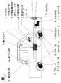
本発明の第1実施形態を図1から図9までの図面に基づいて説明する。図1は本発明の第1実施形態に係る車間距離制御装置の装置構成を示す配置図であり、図1において、レーダー1は車両前面に取り付けられ、自車両前方に位置する複数の車両の位置を測定する。前方カメラ2aはCCDカメラ等によって構成され、車両前面の適宜位置に取り付けられ、道路上に引かれた白線を検出することで走行車線を認識する。後方カメラ2bは車両背面に取り付けられ、自車両後方に位置する複数の車両の位置を検出する。側方カメラ2cは左右の車両側面にそれぞれ1個ずつ取り付けられ、前方のレーダー1と後方カメラ2bの死角となる車両側方に位置する車両の位置を検出する。<< First Embodiment >>
1st Embodiment of this invention is described based on drawing from FIG. 1 to FIG. FIG. 1 is a layout diagram showing a device configuration of an inter-vehicle distance control device according to a first embodiment of the present invention. In FIG. 1, a
車速センサ3はロータリーエンコーダーをホイールに取り付けることで実現でき、ホイールの回転速度に応じた周期のパルス列を出力し、車速の計測値を得る。 The
マイクロコンピュータ4はプロセッサ本体とその周辺部品から構成され、レーダー1,前方カメラ2a,後方カメラ2b,側方カメラ2c,車速センサ3及び後述する車間距離制御操作スイッチ5からの信号を内蔵メモリに記録されたプログラムに従って処理し、各アクチュエータ(スロットルアクチュエータ8,ブレーキアクチュエータ11)に対する制御指令値が算出され、アクチュエータ8,11を制御するコントローラ(スロットルコントローラ7,ブレーキコントローラ10)へ制御指令値を伝達する。The
車間距離制御操作スイッチ5は、たとえばハンドルに取り付けられ、図2に示すように複数の操作スイッチ5a,5b,5cから構成され、車間距離制御の開始/中断、運転者が希望する走行速度(以下、設定車速という。)の設定を行う。たとえば、スイッチ5aを押すと、スイッチを押した時点における自車の走行速度が設定車速として設定される(表示「制御開始」)。また、スイッチ5bを押すと、車間距離制御を中断する(表示「中断」)。車間距離制御を一度中断した後でスイッチ5cを押すと、中断する以前の設定車速が再び設定車速に設定されて車間距離制御が再開される(表示「制御再開」)。また、設定された設定車速は、スイッチ5aを押すことで低速側に修正され、スイッチ5cを押すことで高速側に修正される(スイッチ5a,5cのもう一つの表示「減速」及び「加速」がその意味である)。 The inter-vehicle distance
図1に戻り、方向指示器6は二方向に操作可能なレバーであり、レバーの位置によって左方向、右方向の方向指示器を点灯させるとともに、マイクロコンピュータ4に運転者の車線変更の意思と目標車線の方向を表す信号を伝達するインターフェースとしての役割も果たす。 Returning to FIG. 1, the
スロットルコントローラ7は、マイクロコンピュータ4から指令されたスロットル開度指令値に基づき、スロットルアクチュエータ8によってスロットル開度を調整してエンジン出力を制御する。 The
ブレーキコントローラ10は、マイクロコンピュータ4から指令されたブレーキ圧指令値に基づき、ブレーキアクチュエータ11によってブレーキ圧を調整して車両に発生する制動力を制御する。 The
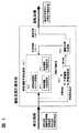
マイクロコンピュータ4は内蔵されているソフトウェア形態により、図3に示す3つの機能ブロック4a,4b,4cから構成されている。 The
ここで、図4に示すような道路状況における動作を例に挙げて、各機能ブロック4a,4b,4cの具体的な処理内容を説明する。 Here, specific processing contents of each of the
図4は片側二車線道路において、右車線を他車Aおよび他車B、左車線を自車Mおよび他車Cが走行しており、左車線を走行する二台の車両M,Cの速度よりも右車線を走行する二台の車両A,Bの速度が速い場面を想定している。このとき、自車Mの運転者は、何らかの理由で右車線に車線変更する意思を持っているが、右車線を他車A及び他車Bが走行しているため、直ちに車線変更するのを躊躇している状況にあるものとする。 FIG. 4 shows the speed of two vehicles M and C traveling in the left lane in which the other vehicle A and other vehicle B are traveling in the right lane, and the own vehicle M and other vehicle C are traveling in the left lane. It is assumed that the two vehicles A and B traveling in the right lane are faster. At this time, the driver of the own vehicle M has an intention to change the lane to the right lane for some reason, but since the other vehicle A and the other vehicle B are traveling on the right lane, the driver must change the lane immediately. Suppose you are in a state of hesitation.
説明の便宜上、道路上に座標系を導入する。道路の進行方向(以下、縦方向という。)に沿ってx軸をとり、自車M、他車A、他車B、他車Cの座標をそれぞれx0,x1,x2,x3で表現する。また、各車の縦方向の速度をそれぞれv0、v1、v2、v3で表現する。なお、座標系の原点は適当な位置に設定されているものとする(以下の説明は原点の位置をどのようにとっても等しく成立する)。また、道路進行方向と垂直方向(以下、横方向という。)に座標軸をとり、車線を区切るレーンマーカー(白線)上が原点、左車線の中央を1、右車線の中央を-1とする正規化された座標軸をy軸にとる。各車のy座標をそれぞれy0、y1、y2、y3で表す。For convenience of explanation, a coordinate system is introduced on the road. The x axis is taken along the traveling direction of the road (hereinafter referred to as the vertical direction), and the coordinates of the own vehicle M, the other vehicle A, the other vehicle B, and the other vehicle C are respectively x0 , x1 , x2 , x3 Express with Also, the vertical speed of each car is expressed as v0 , v1 , v2 , and v3 , respectively. It is assumed that the origin of the coordinate system is set to an appropriate position (the following description is equally valid regardless of the origin position). Also, the coordinate axis is taken in the direction perpendicular to the road direction (hereinafter referred to as the lateral direction), the origin is on the lane marker (white line) that separates the lane, the center of the left lane is 1, and the center of the right lane is -1. The normalized coordinate axis is taken as the y-axis. The y coordinate of each car is represented by y0 , y1 , y2 , and y3 , respectively.
本発明に係る周囲車両検出手段を構成するレーダー1およびカメラ2a,2b,2cによって他車が検出された場合、この検出された車両にはマイクロコンピュータによる処理の過程で固有のID番号が割り当てられ、以後、レーダー1およびカメラ2a,2b,2cが見失うまで同一のID番号によって区別し、管理される。ここでは、自車のID番号を0とし、他車A、他車B、他車CのID番号としてそれぞれ1、2、3が割り当てられたものとする。 When another vehicle is detected by the
検出された車両に関しては、自車との縦方向の車間距離が測定される。図4の場合、x1-x0、x2-x0、x3-x0の値が測定されることになる。座標系の原点は任意にとることができるので、自車位置x0の値を適当に定めることによって、x0、x1、x2、x3すべての座標値を確定する。With respect to the detected vehicle, the inter-vehicle distance in the vertical direction from the own vehicle is measured. In the case of FIG. 4, the values x1 -x0 , x2 -x0 , x3 -x0 are measured. Since the origin of the coordinate system can be arbitrarily set, the coordinate values of all of x0 , x1 , x2 , and x3 are determined by appropriately determining the value of the vehicle position x0 .
また、周囲車両検出手段では、自車Mと他車A,B,Cの横方向の相対位置も測定することができる。すなわち、車線検出手段を構成する前方カメラ2aによる白線検出結果と照合することで、各車両の車線位置であるy0、y1、y2、y3の座標値もすべて確定する。The surrounding vehicle detection means can also measure the relative position in the lateral direction of the own vehicle M and the other vehicles A, B, and C. That is, all the coordinate values of y0 , y1 , y2 , and y3 that are the lane positions of each vehicle are determined by collating with the result of white line detection by the
さらに、周囲車両検出手段で測定された縦方向の車間距離の測定値の時間的変化を計算することによって、各車の縦方向の相対速度であるv1-v0、v2-v0、v3-v0を近似的に得ることができる。自車速度であるv0は自車速度検出手段を構成する車速センサ3で測定することができるので、各車の縦方向の対地速度であるv0,v1,v2,v3の座標値もすべて確定する。Furthermore, by calculating the temporal change in the measured value of the vertical inter-vehicle distance measured by the surrounding vehicle detection means, v1 -v0 , v2 -v0 , which are the vertical relative speeds of each vehicle, v3 -v0 can be obtained approximately. Since the vehicle speed v0 can be measured by the
図3に戻り、以上の自車Mおよび周囲車両A,B,Cの測定値は、すべて運転目標計画手段4aと制御対象車両決定手段4bに送られる。 Returning to FIG. 3, all the measured values of the vehicle M and the surrounding vehicles A, B, and C are sent to the operation
運転目標計画手段4aの構成を図5に示すが、この運転目標計画手段4aは演算ブロック4a−1〜4a−6の機能ブロックから構成され、自車および検出された周囲車両の情報、設定速度の情報および方向指示器の作動状態の情報から、自車が現在置かれた周囲状況に適した運転目標計画を生成する。 The configuration of the operation target planning means 4a is shown in FIG. 5. This operation target planning means 4a is composed of functional blocks of
具体的には、現在時刻tからT秒先の未来の時刻t+Tまでの時間区間(以下、予測区間という。)における追従目標車両のID番号i*(τ)と自車が走行すべき車線位置y*(τ)を生成する。ここで、τは予測区間内の時刻を表す変数である。Specifically, the ID number i* (τ) of the tracking target vehicle in the time interval from the current time t to a future time t + T that is T seconds ahead (hereinafter referred to as the prediction interval) and the host vehicle should travel A lane position y* (τ) is generated. Here, τ is a variable representing the time within the prediction interval.
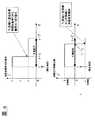
図4に示す場面における運転目標計画手段4aの出力結果の一例を図6に示す。 An example of the output result of the operation target planning means 4a in the scene shown in FIG. 4 is shown in FIG.
図6は、時刻τ1秒後に追従対象車両を他車Cから他車Aに切り替えて、時刻τ2秒後に左車線から右車線に車線変更を開始することを意味する運転目標計画が出力されている例を示している。これは、現時刻からτ1秒間は現在の追従対象車両である他車Cに対する追従走行を続行し、他車Aとの車間距離を広げた後で、追従対象車両を他車Aに切り替えることで加速を開始し(他車Cよりも他車Aの速度の方が速い)、τ2秒後に右車線に車線変更を開始することで右車線の流れに乗るという運転行動を計画したことになる。具体的な運転目標計画の算出アルゴリズムについては後述する。FIG. 6 shows a driving target plan which means that the following target vehicle is switched from the other vehicle C to the other vehicle A after the time τ1 second, and the lane change is started from the left lane to the right lane after the time τ2 seconds. An example is shown. This is to follow the other vehicle C, which is the current tracking target vehicle, for τ1 second from the current time, and after changing the inter-vehicle distance with the other vehicle A, the tracking target vehicle is switched to the other vehicle A. Acceleration started at (the speed of the other car A is faster than the other car C), and the driving action to get on the flow of the right lane by starting the lane change to the right lane after τ2 seconds Become. A specific operation target plan calculation algorithm will be described later.
図3に戻り、制御対象車両決定手段4bでは、運転目標計画手段4aからの出力に基づいて、検出された車両の中から車間距離制御の対象となる車両を選択し、選択された先行車のデータを車間距離制御操作量演算手段4cに転送する。ここでは単純に現在時刻の追従目標車両i*(t)で指定されるID番号(以下、簡単のためIと表記)を持つ車両を車間距離制御の対象車両として選択するものとする。Returning to FIG. 3, the control target
この車間距離制御操作量演算手段4cには、次式のようなベクトルデータxpが送られる。Vector data xp as shown in the following equation is sent to the inter-vehicle distance control operation amount calculation means 4c.

車間距離制御操作量演算手段4cには、入力情報として先行車データの他に、自車速度v0と設定車速v0*が入力される。自車速度v0は車速センサ3の測定値が、設定車速v0*は車間距離制御操作スイッチ5の操作によって設定された値がそれぞれ入力される。In addition to the preceding vehicle data, the host vehicle speed v0 and the set vehicle speed v0* are input to the inter-vehicle distance control operation amount calculation means 4c as input information. A measured value of the
この車間距離制御操作量演算手段4cでは、入力された先行車情報、自車速度、設定車速の測定値から、車間距離制御を実行するために走行制御手段を構成するアクチュエータ8,11に対する操作量指令値を算出して、各アクチュエータ8,11のコントローラ7,10に転送するまでの処理を行う。ここで実行される処理は大きく分けて、運転者の走行感覚に適合した追従特性を実現するための目標制御量を算出する処理と、算出された目標制御量を実現するために必要なアクチュエータの操作量を算出する処理の二種類から構成されている。 In the inter-vehicle distance control operation amount calculation means 4c, the operation amounts for the
目標制御量として、ここでは自車の速度を用いるものとすると、目標制御量算出処理は、先行車情報xp、自車速度v0、設定車速v0*を入力情報として、自車の目標速度vcを出力するコントローラの演算になる。そのような形式の車間距離制御装置に関しては、例えば特開2000−135934号公報に開示されている発明のアルゴリズムを利用することができる。Assuming that the speed of the host vehicle is used here as the target control amount, the target control amount calculation process uses the preceding vehicle information xp , the host vehicle speed v0 , and the set vehicle speed v0* as input information. It is the calculation of the controller that outputs the speed vc . For such an inter-vehicle distance control device, for example, the algorithm of the invention disclosed in Japanese Patent Laid-Open No. 2000-135934 can be used.
なお、車間距離制御の対象となる先行車が選択されない場合には、自車速度を設定速度に一致させるような車速制御のアルゴリズムが実行され、運転者の走行感覚に適合した速度調整が行われるような目標速度が出力される。 Note that when a preceding vehicle that is subject to inter-vehicle distance control is not selected, a vehicle speed control algorithm that matches the vehicle speed with the set speed is executed, and a speed adjustment that matches the driving sensation of the driver is performed. Such a target speed is output.
特開2000−135934号公報に開示された発明では、目標速度算出アルゴリズムを線形パラメータ変化システム(Linear Parameter Varying System、LPVシステム)として構成しており、以下のような状態方程式の形で表現することができる。 In the invention disclosed in Japanese Patent Laid-Open No. 2000-135934, the target speed calculation algorithm is configured as a linear parameter changing system (LPV system) and expressed in the form of the following state equation: Can do.
車間距離制御操作量演算手段4cで実行されるもう一つの処理、すなわち算出された目標速度に自車速を一致させるために必要なアクチュエータの操作量を算出する処理に関しては、例えば目標車速vcに対して自車の速度v0が次式に従って追従するようなモデルマッチング制御の問題として定式化することができる。With respect to another process executed by the inter-vehicle distance control operation amount calculation means 4c, that is, a process for calculating the operation amount of the actuator necessary for making the own vehicle speed coincide with the calculated target speed, for example, the target vehicle speed vc is set. On the other hand, it can be formulated as a problem of model matching control in which the speed v0 of the own vehicle follows according to the following equation.
以上説明したマイクロコンピュータ4における処理手順を、図7のフローチャートにまとめる。 The processing procedure in the
まずステップ1では車間距離制御操作スイッチ5の操作が検出され、ステップ2では検出したスイッチ5の操作から設定車速の更新が行われる。ステップ1でスイッチ5の操作が検出されなかった場合は、前回の処理ルーチンにおける設定内容がそのまま引き継がれる。 First, in
ステップ3では設定車速が設定されているかどうかが判定される。車間距離制御操作スイッチ5の中断スイッチ5bが操作されるなどして設定車速が設定されていない場合には、車間距離制御の実行を中止するため、ステップ11へ進んでアクチュエータへ8,11の指令値をクリアして処理を終了する。ステップ3にて設定車速が設定されている場合には、車間距離制御を実行するためにステップ4以下の処理へと進む。 In
ステップ4では、方向指示器6の作動状態が読み込ま、ステップ5では、レーダー1、カメラ2a,2b,2c、車速センサ3の各センサの検出信号が読み込まれる。 In
ステップ6では、センサ1,2a,2b,2c,3で検出された他車両を前回の処理ルーチンの検出結果と照合し、検出車両のIDの更新と、各車両の座標値の計算が行われる。 In
ステップ7では、運転目標計画手段4aの処理が実行され、追従目標車両のIDと目標車線位置の信号が生成される。 In
ステップ8では、運転目標計画手段4aの出力に基づいて制御対象車両決定手段4bにて車間距離制御の対象となる車両を選択し、対応する車両のデータを(1)式のフォーマットで生成する。 In
ステップ9では、車間距離制御操作量演算手段4cの処理が実行され、
ステップ10では、算出されたスロットルとブレーキ操作量の指令値をそれぞれスロットルコントローラ7とブレーキコントローラ10に転送して、処理を終了する。 In
以上の処理を繰り返すことで車間距離制御を実行するが、従来の車間距離制御装置との違いは、車間距離制御の対象となる先行車を物理的な車両の位置関係だけで選択するのではなく、自車にとって最も望ましい運転操作が実現できると予想される車両を周囲状況に基づいて選択する機能を持っていることである。このような本発明に特徴的な機能を実現する処理を行っているのが運転目標計画手段4aであり、以下にそのアルゴリズムを説明する。 The inter-vehicle distance control is executed by repeating the above processing, but the difference from the conventional inter-vehicle distance control device is not to select the preceding vehicle that is the target of the inter-vehicle distance control based only on the physical vehicle positional relationship. The vehicle has a function of selecting a vehicle that is expected to realize the most desirable driving operation for the vehicle based on the surrounding situation. It is the operation target plan means 4a that performs the processing for realizing the functions characteristic of the present invention, and its algorithm will be described below.
運転目標計画手段4aは、図5に示すように大きく分けて車群運動予測演算部4a−1、予測運動評価演算部4a−5、運転目標生成部4a−6の3つの演算ブロックから構成されている。 As shown in FIG. 5, the driving target planning means 4a is roughly composed of three calculation blocks, a vehicle group motion
運転目標生成部4a−6は、まず自車に対する現在からT秒先の未来までの適当な運転目標、すなわち追従目標車両のID番号i(τ)と自車が走行すべき車線位置y(τ)を生成する。実際の計算においては、連続時間関数の形では扱いにくいので、予測区間をNステップに分割した以下の離散時間系列を生成する。 The driving
車群運動予測演算部4a−1では、与えられた運転目標系列IN、YNに従って自車を運転した場合の自車および周囲車両の運動の予測を行う。予測の結果として算出される全車両の状態量の系列を以下のように表記する。The vehicle group motion
具体的な予測値の計算は、車群運動予測演算部4a−1の構成要素である車間距離制御演算ロジック演算部4a−2、自車運動予測演算部4a−3、他車運動予測演算部4a−4の3つの演算ブロックを利用することで実行される。 The specific prediction value is calculated by calculating the inter-vehicle distance control calculation
車間距離制御演算ロジック演算部4a−2は、車間距離制御操作量演算手段4cにおける目標制御量演算のアルゴリズムと同一のアルゴリズムで構成される。ただし、先行車がINによって指定されていることと、ここで計算される指令値が実際の制御ではなく予測のために用いられる点が異なっている。予測においては時間が離散化されているので、(3)式のアルゴリズムはここでは次式のように計算される。The inter-vehicle distance control calculation
自車運動予測演算部4a−3は、自車の物理的な運動を予測する演算を行うブロックである。走行方向の運動は、車間距離制御ロジック演算部4a−2の結果を受けて、(5)式の車速制御が完全に実現されたことを想定して予測が立てられる。すなわち、
一方、横方向の運動は、与えられた目標系列YNに従って、次式のモデルによって予測が立てられる。On the other hand, the lateral motion is predicted by the following model according to the given target sequence YN.
予測運動評価演算部4a−5では、あらかじめ設定された運転行動の良否を判定する基準に従って、車群運動予測演算部4a−1で予測された運動を数値的に評価する。例えば、次式のような評価関数を構成し、その値を計算することで生成された運転目標系列IN、YNに対する評価値を定める。The predicted motion
方向指示器6の操作を検出した場合には、運転者の車線変更の意思を反映して、自車の車線位置を評価する項を加えることが考えられる。例えば、次の評価式を導入することでそのような評価を含ませることができる。 When the operation of the
このように、評価関数を具体的に定義して、適当な運転目標系列IN、YNを与えると、それに対する評価値J(IN,YN)を計算することができるので、運転目標系列の生成とそれに対する評価値の計算を繰り返すことによって、評価値の良い運転目標系列を見つけることができる。In this way, when an evaluation function is specifically defined and an appropriate operation target sequence IN , YN is given, an evaluation value J (IN , YN ) can be calculated. By repeating the generation of the series and the calculation of the evaluation value for the series, an operation target series having a good evaluation value can be found.
i(τ)のとり得る値は、検出している他車両のID番号と、追従対象車両を設定しないことを表す値0(自車速を設定車速に一致させる車速制御を実行することになる)のいずれかであるので、INのとり得るパターンの数は有限である。例えば、図4の場合には、パターン数は4N通りとなる。また、y(τ)のとり得る値は左車線を表す1と右車線を表す−1の2通りしかないので、YNのとり得るパターン数は2N通りである。従って、図4の場合には、運転目標系列の数は全部で4N・2N=8N通りしかないので、理論的にはすべてのパターンを調べることによって最適な運転目標系列を見つけることができる。Possible values of i (τ) are the ID number of the detected other vehicle and a value of 0 indicating that the following vehicle is not set (vehicle speed control is executed to match the own vehicle speed with the set vehicle speed) because it is one of the number of patterns that can be taken of IN is finite. For example, in the case of FIG. 4, the number of patterns is4N . Since there are only two possible values of y (τ), 1 representing the left lane and −1 representing the right lane, YN can take 2N patterns. Therefore, in the case of Fig. 4, since there are only 4N · 2N = 8N operation target series in total, the optimal operation target series can be found theoretically by examining all patterns. it can.
実際には、8N通りのパターンの中には、何度も車線変更を繰り返すような明らかに受け入れ難いパターンや、自車の後方車両を追従対象車両に選ぶような無意味なパターンも多数含まれており、探索空間を適当に制限することによって、効率的な解の探索が可能である。例えば、予測区間内で追従目標車両の切り替えと車線変更をそれぞれ1回だけに制限すれば、探索すべきパターンの総数は、図4の場合、(3N+1)・(N+1)=3N2+4N+1通りに減少する。このように探索空間を制限することによって得られる解は最適解であるという保証はないものの、多くの場合、十分に合理性のある運転目標となっていることが期待できる。In fact, the 8N patterns include many patterns that are clearly unacceptable, such as repeated lane changes, and meaningless patterns that select the vehicle behind you as the vehicle to follow. Therefore, an efficient solution search is possible by appropriately limiting the search space. For example, if the switching of the target vehicle and the lane change are limited to once each in the prediction section, the total number of patterns to be searched is (3N + 1) · (N + 1) = 3N in the case of FIG. Decrease as2 + 4N + 1. Although there is no guarantee that the solution obtained by limiting the search space in this way is an optimal solution, in many cases it can be expected that the operation target is sufficiently rational.
以上のように運転目標系列の生成と評価を繰り返し、最も良い評価値が算出された運転目標系列を、運転目標計画手段4aの演算結果として出力することが、運転目標生成部4a−6のアルゴリズムの内容である。 As described above, the generation and evaluation of the operation target sequence is repeated, and the operation target sequence for which the best evaluation value is calculated is output as the calculation result of the operation target planning means 4a. The algorithm of the operation
以上説明した運転目標計画手段4aにおけるアルゴリズムを図8のフローチャートにまとめた。 The algorithm in the operation target plan means 4a described above is summarized in the flowchart of FIG.
まずステップ7−1では、自車および周囲車両の検出データx(f)が読み込まれ、このときのx(f)は、後段の運動予測演算の初期値として利用される。 First, in step 7-1, detection data x (f) of the own vehicle and surrounding vehicles is read, and x (f) at this time is used as an initial value of the motion prediction calculation at the subsequent stage.
ステップ7−2では、設定車速の値と方向指示器6の作動状態に関する信号がロードされ、ステップ7−3でロードされた情報をもとに評価関数(26)、(22)式が構成される。 In step 7-2, signals relating to the value of the set vehicle speed and the operating state of the
次のステップ7−4以降のステップにて運転目標生成部4a−6の探索演算が開始される。 In the next step 7-4 and subsequent steps, the search calculation of the
まず、ステップ7−5で、探索対象となる目標系列IN、YNを一つ選択する。ステップ7−6では、ステップ7−1で設定された初期値をもとに、ステップ7−5で選択された目標系列に従って、(10)〜(21)式を用いて自車と周囲車両の運動予測を実行する。First, at step 7-5, one target sequence IN , YN to be searched is selected. In step 7-6, based on the initial value set in step 7-1, according to the target series selected in step 7-5, the own vehicle and the surrounding vehicles are calculated using equations (10) to (21). Perform motion prediction.
ステップ7−7では、ステップ7−6で算出された運動予測の結果から、ステップ7−3で構成した評価関数に従って、選択された目標系列の評価値を算出する。 In Step 7-7, the evaluation value of the selected target series is calculated from the result of the motion prediction calculated in Step 7-6 according to the evaluation function configured in Step 7-3.
ステップ7−8では、これまで探索対象となった目標系列の中で最も評価の高い(評価値の小さい)最適目標系列の評価値とステップ7−7で算出された評価値とが比較される。ここで、算出された評価値の方が小さい場合にはステップ7−9で最適目標系列を更新するが、そうでない場合には最適目標系列の更新は行わずにステップ7−4に戻る。In step 7-8, the evaluation value of the optimal target sequence having the highest evaluation (small evaluation value) among the target sequences that have been searched so far is compared with the evaluation value calculated in step 7-7. . If the calculated evaluation value is smaller, the optimal target sequence is updated in step 7-9. If not, the optimal target sequence is not updated and the process returns to step 7-4.
なお、最適目標系列が定義されていない(初回の探索演算時)場合には、無条件に最適目標系列として採用される。いずれの場合も更新処理が終了した後は、ステップ7−4へ戻り、未探索の目標系列があれば探索を続行し、すべての目標系列候補の探索が終了した場合には、ステップ7−10へ進み、最適目標系列を出力して演算が終了する。 If the optimum target sequence is not defined (during the first search calculation), it is unconditionally adopted as the optimum target sequence. In any case, after the update process is completed, the process returns to step 7-4. If there is an unsearched target sequence, the search is continued. If the search for all target sequence candidates is completed, step 7-10 is performed. , The optimal target sequence is output, and the calculation ends.
以上説明した車間距離制御装置全体の実際の動作がどのようなものになるかについて、図9の場面を例にとって説明する。 The actual operation of the entire inter-vehicle distance control apparatus described above will be described with reference to the scene of FIG. 9 as an example.
図9(a)に示す場面は、自車Mが、車間距離制御装置の設定車速を100km/hにセットして左車線を走行しており、右車線の自車Mのすぐ後ろを他車Aがほぼ同じ速度で並走している状況において、左車線前方に85km/hで走行する他車Bを新たに検出した状況を示している。この場合、左車線に留まって他車Bに追従を開始すると、追従のために減速を強いられ、設定車速を下回る速度で走行することになるが、その一方で他車Aが存在するために右車線に車線変更することは困難である。従って、運転目標計画手段4aでは左車線に留まり、他車Bに追従を続けるという目標系列が生成され、それに基づいて自車Mは他車Bに対する車間距離制御を開始し、他車Bの走行速度である85km/hまで緩やかに減速していく。 In the scene shown in FIG. 9A, the own vehicle M is traveling in the left lane with the set vehicle speed of the inter-vehicle distance control device set to 100 km / h, and another vehicle is directly behind the own vehicle M in the right lane. In the situation where A is running in parallel at substantially the same speed, the situation is shown in which another vehicle B running at 85 km / h in front of the left lane is newly detected. In this case, if the vehicle stays in the left lane and starts following the other vehicle B, it is forced to decelerate for following and travels at a speed lower than the set vehicle speed, but on the other hand, the other vehicle A exists. It is difficult to change the lane to the right lane. Accordingly, the driving target planning means 4a generates a target series that stays in the left lane and continues to follow the other vehicle B. Based on this, the own vehicle M starts the inter-vehicle distance control for the other vehicle B, and the other vehicle B travels. Slowly decelerate to 85 km / h, which is the speed.
同図(b)は、この減速途中で、他車Aの後方に他車Cを新たに検出し、他車Aに追い抜かれたタイミングで右方向の方向指示器6を操作した場面を示す。 FIG. 4B shows a scene in which another vehicle C is newly detected behind the other vehicle A and the
この時、運転目標計画手段4aでは、しばらく他車Bに対する追従走行を続けた後で、追従目標車両を他車Aに変更して加速を開始し、その後で右車線に車線変更を開始するという目標系列を生成している。この場合、近い未来において追従対象車両の切り替えや車線変更を指示する目標を指示していることになるが、同図(b)の時点における現在の追従対象車両は依然として他車Bのままなので、車間距離制御装置としては他車Bに対する追従走行を続けることになる。 At this time, the driving target planning means 4a continues to follow the other vehicle B for a while, then changes the following target vehicle to the other vehicle A and starts acceleration, and then starts changing the lane to the right lane. A target series is generated. In this case, in the near future, the target for instructing the switching of the tracking target vehicle or the lane change is instructed, but the current tracking target vehicle at the time of FIG. The inter-vehicle distance control device continues to follow the other vehicle B.
その後、さらに時間が進んで、同図(c)に示すように他車Aとの車間距離が開いてきた時点では、運転目標計画手段4aはただちに追従目標車両を他車Aに切り替えて、その後で右車線に車線変更する目標系列を生成している。この時は他車Aを車間距離制御対象の先行車として選択するので、ただちに加速を開始することになる。 Thereafter, when the time further advances and the inter-vehicle distance with the other vehicle A increases as shown in FIG. 5C, the driving target planning means 4a immediately switches the following target vehicle to the other vehicle A, and thereafter The target sequence to change the lane to the right lane is generated. At this time, since the other vehicle A is selected as the preceding vehicle subject to the inter-vehicle distance control, acceleration is immediately started.
特開2000−135934号公報などに開示されている車間距離制御装置では、車線変更した後で加速を開始する構成となっているので、同図(c)のように後方から別の車両Cが接近しているような場面では、加速せずに車線変更を開始する操作には運転者が違和感を覚える可能性があるが、本例の車間距離制御装置によれば、同図(c)の状況において他車Aとの車間距離が開いてきたら追従目標車両を他車Aに切り替えて加速を開始し、その後で右車線に車線変更するので、運転者が違和感を覚えることがなく自然な運転操作を実現できる。 In the inter-vehicle distance control device disclosed in Japanese Unexamined Patent Publication No. 2000-135934 and the like, acceleration is started after changing the lane, so that another vehicle C can be seen from the rear as shown in FIG. In an approaching situation, the driver may feel uncomfortable with the operation of starting lane change without accelerating, but according to the inter-vehicle distance control device of this example, When the inter-vehicle distance from the other vehicle A increases in the situation, the target vehicle is switched to the other vehicle A to start acceleration, and then the lane is changed to the right lane. Operation can be realized.
《第2実施形態》
次に本発明の第2実施形態を図10から図13の図面を参照しながら説明する。<< Second Embodiment >>
Next, a second embodiment of the present invention will be described with reference to FIGS. 10 to 13.
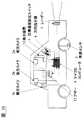
図10は本発明の第2実施形態に係る運転操作支援装置を示す配置図である。基本的な装置構成は図1に示す第1実施形態に係る車間距離制御装置と同じであるが、本実施形態の構成では車間距離制御の実行を想定していないので、スロットルやブレーキを自動制御するためのコントローラ7,10やアクチュエータ8,11は運転操作支援装置の必須構成要件とはならない。そのため、図10ではエンジンやブレーキの記載を省略している。FIG. 10 is a layout view showing a driving operation support apparatus according to the second embodiment of the present invention. The basic device configuration is the same as the inter-vehicle distance control device according to the first embodiment shown in FIG. 1, but the configuration of this embodiment does not assume the execution of inter-vehicle distance control, so the throttle and brake are automatically controlled. Therefore, the
これに代えて第2実施形態に係る運転操作支援装置では、第1実施形態にはなかった表示装置12とブザー13が装備されている。また、本実施形態のカメラ2a,2b,2cは周囲車両の位置だけでなく、周囲車両の方向指示器の点灯状態も検出できるものとする。 Instead, the driving operation support device according to the second embodiment is equipped with the
表示装置12は液晶パネルなどの表示用ディスプレイで構成され、マイクロコンピュータ4から送られてきた支援情報をディスプレイに表示する。 The
ブザー13はマイクロコンピュータ4から送られてきた指令に従って、必要に応じて音を発生し、運転者に注意を喚起する。 The buzzer 13 generates a sound as necessary in accordance with a command sent from the
マイクロコンピュータ4には、図11に示すように、第1実施形態と同じく運転行動計画手段4aが実装されている他、生成された最適目標系列を運転者に提示する情報へと変換する提示情報生成部4dが実装されている。 As shown in FIG. 11, the
このうち、運転目標計画手段4aの構成は図5に示した第1実施形態の構成と基本的に同じであるが、本実施形態の場合、他車の車線変更も予測する構成となっているので、他車運動予測演算部4a−4において他車の横方向運動を予測する処理が加わることになる。具体的には、第1実施形態における(21)式が以下の式で置き換えられる。 Among these, the configuration of the operation target planning means 4a is basically the same as the configuration of the first embodiment shown in FIG. 5, but in the present embodiment, it is also configured to predict lane changes of other vehicles. Therefore, processing for predicting the lateral motion of the other vehicle is added in the other vehicle motion
その他の演算については、第1実施形態と同じである。 Other operations are the same as those in the first embodiment.
提示情報生成部4dでは、運転目標計画手段4aで生成された目標系列から運転者に提示する情報を提示する。具体的には、まずINをチェックして追従対象車両の切り替えが行われているかどうかを調べる。切り替えが行われている場合には、どの車両を追従対象車両に切り替えているかを調べ、該当車両が自車線への車線変更を予告する方向指示器を点灯させている場合には、自車両の前方に他車が割り込んでくる可能性があることを予測していることになるので、ブザーを鳴らす指令信号をブザー13に送る。また、INの先頭成分であるi(f)に対応する車両を追従対象車両として車間距離制御を行った場合に生成される自車の目標速度を車間距離制御ロジック演算部4a−2の処理を呼び出して算出し、自車の現在の走行速度と比較する。そして、自車の走行速度の方が高ければ減速を推奨する信号をドライバーに表示し、自車の走行速度の方が低ければ加速を推奨する信号を表示する描画信号を表示装置12に送る。In the presentation
また、YNをチェックして走行車線の切り替えを含む系列が生成されているかどうかを調べ、走行車線の切り替えを含んでいれば、車線変更先を推奨する信号を表示する描画信号を表示装置12に送る。Also, YN is checked to determine whether a sequence including switching of driving lanes has been generated. If it includes switching of driving lanes, a drawing signal for displaying a signal recommending a lane change destination is displayed on the
ここで、本例の表示装置12に描画される画像の一例を図12に示す。左側に加減速の推奨操作の内容、右側に車線変更の推奨操作の内容が矢印の形で表示される。 Here, an example of an image drawn on the
以上説明した運転操作支援装置全体の実際の動作がどのようなものになるかについて、図13の場面を例にとって説明する。 The actual operation of the entire driving operation support apparatus described above will be described with reference to the scene of FIG.
図13(a)は、自車Mと他車Aが左車線を走行し、他車Bが右車線を走行している場面であり、自車Mは他車Aとの車間距離を縮めるためにゆっくりと加速している状況を示している。 FIG. 13A is a scene in which the own vehicle M and the other vehicle A are traveling in the left lane and the other vehicle B is traveling in the right lane, and the own vehicle M reduces the inter-vehicle distance from the other vehicle A. It shows the situation of accelerating slowly.
ここで図13(b)に示すように、他車Bが左方向の方向指示器を操作し、車線変更を予告してきたとする。この時、運転目標計画手段4aは、他車Bの割り込みを検出して追従対象車両を他車Bへ切り替える目標系列を生成している。これに伴って、ブザー13が鳴らされて運転者に注意を喚起するとともに、割り込みに備えるために減速を推奨する信号が表示装置12に描画される。 Here, as shown in FIG. 13B, it is assumed that the other vehicle B has operated the left direction indicator and has notified the lane change. At this time, the driving
図13(c)に示す場面は、他車Bが車線変更を完了して右車線に1台も車両が走行していない状況になっている。この時、運転目標計画手段4aは、追従対象車両の選択を解除(設定車速への車速制御に移行)した後、右車線に車線変更する目標系列を生成している。これに対応して、運転者には右車線への車線変更を指示する信号が表示装置12に描画される。 In the scene shown in FIG. 13C, the other vehicle B completes the lane change and no vehicle is traveling in the right lane. At this time, the driving target planning means 4a generates a target sequence for changing the lane to the right lane after canceling the selection of the tracking target vehicle (shifting to the vehicle speed control to the set vehicle speed). Correspondingly, a signal instructing the driver to change the lane to the right lane is drawn on the
以上のように、本実施形態の運転操作支援装置によれば、運転目標計画手段4aで生成される目標系列の情報を表示装置12に表示することで、周囲状況を考慮した適切な運転操作を運転者に推奨して、運転を支援することができる。 As described above, according to the driving operation support device of the present embodiment, by displaying the information on the target sequence generated by the driving
なお、以上説明した実施形態は、本発明の理解を容易にするために記載されたものであって、本発明を限定するために記載されたものではない。したがって、上記の実施形態に開示された各要素は、本発明の技術的範囲に属する全ての設計変更や均等物をも含む趣旨である。 The embodiment described above is described for facilitating the understanding of the present invention, and is not described for limiting the present invention. Therefore, each element disclosed in the above embodiment is intended to include all design changes and equivalents belonging to the technical scope of the present invention.
1…レーダー(周囲車両検出手段)
2a…前方カメラ(車線検出手段、周囲車両検出手段)
2b…後方カメラ(周囲車両検出手段)
2c…側方カメラ(周囲車両検出手段)
3…車速センサ(自車速度検出手段)
4…マイクロコンピュータ
4a…運転目標計画手段
4a−1…車群運動予測演算部
4a−2…車間距離制御ロジック演算部
4a−3…自車運動予測演算部
4a−4…他車運動予測演算部
4a−5…予測運動評価演算部
4a−6…運転目標生成部
4b…制御対象車両決定手段
4c…車間距離制御操作量演算手段
4d…提示情報生成部
5…車間距離制御操作スイッチ(目標速度設定手段)
6…方向指示器(車線変更意思検出手段)
7…スロットルコントローラ(走行制御手段)
8…スロットルアクチュエータ(走行制御手段)
9…エンジン
10…ブレーキコントローラ(走行制御手段)
11…ブレーキアクチュエータ(走行制御手段)
12…表示装置(運転支援情報表示手段)
13…ブザー(運転者注意喚起手段)
1 ... Radar (Ambient vehicle detection means)
2a ... Front camera (lane detection means, surrounding vehicle detection means)
2b ... Rear camera (surrounding vehicle detection means)
2c ... Side camera (surrounding vehicle detection means)
3 ... Vehicle speed sensor (own vehicle speed detection means)
DESCRIPTION OF
6. Direction indicator (lane change intention detection means)
7. Throttle controller (travel control means)
8 ... Throttle actuator (travel control means)
9 ...
11 ... Brake actuator (travel control means)
12. Display device (driving support information display means)
13 ... Buzzer (driver alerting means)
Claims (16)
Translated fromJapanese前記自車の周囲を走行する他車両を検出する周囲車両検出手段と、
前記自車の周囲の車線を検出する車線検出手段と、
前記自車の乗員が希望する走行速度を設定する目標速度設定手段と、
現在から所定時間先までの間の予測区間において前記自車が追従すべき追従目標車両と走行すべき走行目標車線の選択と、追従目標車両及び走行目標車線の切り替えタイミングの算出とを実行する運転目標計画手段と、
前記周囲車両検出手段で検出された車両の中から車間距離制御の対象となる先行車を選択する制御対象車両決定手段と、
前記制御対象車両決定手段で設定された先行車に追従するのに適した自車の加速度又は減速度の目標値を算出する車間距離制御操作量演算手段と、
前記自車の加速度又は減速度を前記車間距離制御操作量演算手段で算出された目標値と一致させるように制駆動力および変速比を制御する走行制御手段と、を備え、
前記運転目標計画手段は、
前記運転目標計画手段が、前記周囲車両検出手段により検出された周囲車両の中から追従目標車両を設定したときは当該追従目標車両に追従するための規範操作量を算出し、前記運転目標計画手段が、追従目標車両を設定しないときは前記目標速度設定手段で設定された目標速度に自車速度を制御するための規範操作量を算出する車間距離制御ロジック演算部と、
前記車間距離制御ロジック演算部で算出された規範操作量に基づいて前記自車の走行方向の運動を予測し、前記運転目標計画手段が前記走行目標車線を指定したときは前記自車の走行方向に対する横方向の運動を予測する自車運動予測演算部と、
前記他車両の走行方向の運動を予測する他車運動予測演算部と、
前記自車運動予測演算部及び前記他車運動予測演算部による予測結果から前記予測区間における前記自車および前記他車両の運動を予測する車群運動予測演算部と、
前記車群運動予測演算部で予測された前記自車および前記他車両の予測結果と、予め設定された自車にとって望ましい走行状態に関する基準との適合度を数値的に評価する予測運動評価演算部と、
前記予測運動評価演算部の評価値が所定の基準を満たすような追従目標車両と目標車線位置の予測区間における選択パターンを生成する運転目標生成部と、
を有し、
前記制御対象車両決定手段は、前記運転目標計画手段で算出された追従目標車両のうち、現在時刻に対応する追従目標車両を制御対象となる先行車に設定することで車間距離制御を実行することを特徴とする車間距離制御装置。Own vehicle speed detecting means for detecting the traveling speed of the own vehicle;
Surrounding vehicle detection means for detecting other vehicles traveling around the own vehicle;
Lane detection means for detecting a lane around the vehicle;
Target speed setting means for setting a travel speed desired by the passenger of the host vehicle;
Driving that performs the selection of the tracking target vehicle to be followed by the host vehicle and the travel target lane to be traveled and the calculation of the switching timing of the tracking target vehicle and the travel target lane in the prediction section from the present to a predetermined time ahead Goal planning means;
Control target vehicle determination means for selecting a preceding vehicle to be subject to inter-vehicle distance control from among the vehicles detected by the surrounding vehicle detection means;
An inter-vehicle distance control operation amount calculating means for calculating a target value of acceleration or deceleration of the own vehicle suitable for following the preceding vehicle set by the control target vehicle determining means;
Travel control means for controlling the braking / driving force and the gear ratio so that the acceleration or deceleration of the host vehicle matches the target value calculated by the inter-vehicle distance control operation amount calculation means,
The operation target planning means includes:
When the driving target planning unit sets a tracking target vehicle from the surrounding vehicles detected by the surrounding vehicle detecting unit, the driving target planning unit calculates a reference operation amount for following the tracking target vehicle; However, when the following target vehicle is not set, an inter-vehicle distance control logic calculation unit that calculates a reference operation amount for controlling the vehicle speed to the target speed set by the target speed setting means,
Based on the reference operation amount calculated by the inter-vehicle distance control logic calculation unit, the movement in the traveling direction of the host vehicle is predicted, and when the driving target planning means designates the traveling target lane, the traveling direction of the host vehicle A vehicle motion prediction calculator that predicts lateral motion relative to the vehicle,
Other vehicle motion prediction calculation unit for predicting the movement of the other vehicle in the traveling direction;
A vehicle group motion prediction calculation unit that predicts the movement of the host vehicle and the other vehicle in the prediction section from the prediction results of the host vehicle motion prediction calculation unit and the other vehicle motion prediction calculation unit;
A predicted motion evaluation calculation unit that numerically evaluates the degree of fit between the prediction results of the own vehicle and the other vehicle predicted by the vehicle group motion prediction calculation unit, and a preset criterion relating to a desired driving state for the own vehicle. When,
A driving target generator for generating a selection pattern in a predicted section of the target vehicle and the target lane position so that the evaluation value of the predicted motion evaluation calculation unit satisfies a predetermined criterion;
Have
The control target vehicle determining means executes inter-vehicle distance control by setting the follow target vehicle corresponding to the current time among the follow target vehicles calculated by the operation target plan means as a preceding vehicle to be controlled. An inter-vehicle distance control device characterized by the above.
前記運転目標計画手段は、前記自車の前方に割り込んでくる可能性がある他車両を追従目標車両の候補に挙げることを特徴とする請求項1記載の車間距離制御装置。The other vehicle motion prediction calculation unit predicts lateral motion relative to the travel direction of the other vehicle in addition to motion in the travel direction of the other vehicle,
2. The inter-vehicle distance control device according to claim 1, wherein the driving target planning means lists other vehicles that may be in front of the host vehicle as candidates for the tracking target vehicle.
前記制御対象車両決定手段は、前記車線変更意思検出手段において運転者の車線変更意思が検出されない場合には、現在の制御対象車両および自車前方に割り込んでくる可能性のある車両以外の車両を制御対象車両として選択しないことを特徴とする請求項1又は2記載の車間距離制御装置。Lane change intention detection means for detecting the driver's intention to change lanes,
When the driver's intention to change lanes is not detected by the lane change intention detection means, the control target vehicle determination means determines a vehicle other than the current control target vehicle and a vehicle that may interrupt the front of the host vehicle. 3. The inter-vehicle distance control device according to claim 1, wherein the inter-vehicle distance control device is not selected as a control target vehicle.
前記自車の周囲を走行する他車両を検出する周囲車両検出手段と、
前記自車の周囲の車線を検出する車線検出手段と、
前記自車の乗員が希望する走行速度を設定する目標速度設定手段と、
現在から所定時間先までの間の予測区間において前記自車が追従すべき追従目標車両と走行すべき走行目標車線の選択と、追従目標車両及び走行目標車線の切り替えタイミングの算出とを実行する運転目標計画手段と、を備え、
前記運転目標計画手段は、
前記運転目標計画手段が、前記周囲車両検出手段により検出された周囲車両の中から追従目標車両を設定したときは当該追従目標車両に追従するための規範操作量を算出し、前記運転目標計画手段が、追従目標車両を設定しないときは前記目標速度設定手段で設定された目標速度に自車速度を制御するための規範操作量を算出する車間距離制御ロジック演算部と、
前記車間距離制御ロジック演算部で算出された規範操作量に基づいて前記自車の走行方向の運動を予測し、前記運転目標計画手段が前記走行目標車線を指定したときは前記自車の走行方向に対する横方向の運動を予測する自車運動予測演算部と、
前記他車両の走行方向の運動を予測する他車運動予測演算部と、
前記自車運動予測演算部及び前記他車運動予測演算部による予測結果から前記予測区間における前記自車および前記他車両の運動を予測する車群運動予測演算部と、
前記車群運動予測演算部で予測された前記自車および前記他車両の予測結果と、予め設定された自車にとって望ましい走行状態に関する基準との適合度を数値的に評価する予測運動評価演算部と、
前記予測運動評価演算部の評価値が所定の基準を満たすような追従目標車両と目標車線位置の予測区間における選択パターンを生成する運転目標生成部と、を有することを特徴とする運転操作支援装置。Own vehicle speed detecting means for detecting the traveling speed of the own vehicle;
Surrounding vehicle detection means for detecting other vehicles traveling around the own vehicle;
Lane detection means for detecting a lane around the vehicle;
Target speed setting means for setting a travel speed desired by the passenger of the host vehicle;
Driving that performs the selection of the tracking target vehicle to be followed by the host vehicle and the travel target lane to be traveled and the calculation of the switching timing of the tracking target vehicle and the travel target lane in the prediction section from the present to a predetermined time ahead A goal planning means,
The operation target planning means includes:
When the driving target planning unit sets a tracking target vehicle from the surrounding vehicles detected by the surrounding vehicle detecting unit, the driving target planning unit calculates a reference operation amount for following the tracking target vehicle; However, when the following target vehicle is not set, an inter-vehicle distance control logic calculation unit that calculates a reference operation amount for controlling the vehicle speed to the target speed set by the target speed setting means,
Based on the reference operation amount calculated by the inter-vehicle distance control logic calculation unit, the movement in the traveling direction of the host vehicle is predicted, and when the driving target planning means designates the traveling target lane, the traveling direction of the host vehicle A vehicle motion prediction calculator that predicts lateral motion relative to the vehicle,
Other vehicle motion prediction calculation unit for predicting the movement of the other vehicle in the traveling direction;
A vehicle group motion prediction calculation unit that predicts the movement of the host vehicle and the other vehicle in the prediction section from the prediction results of the host vehicle motion prediction calculation unit and the other vehicle motion prediction calculation unit;
A predicted motion evaluation calculation unit that numerically evaluates the degree of fit between the prediction results of the own vehicle and the other vehicle predicted by the vehicle group motion prediction calculation unit, and a preset criterion relating to a desired driving state for the own vehicle. When,
A driving operation support device, comprising: a target vehicle that follows the evaluation value of the predicted motion evaluation calculation unit that satisfies a predetermined criterion; and a driving target generation unit that generates a selection pattern in a prediction section of a target lane position. .
前記運転目標計画手段は、前記自車の前方に割り込んでくる可能性がある他車両を追従目標車両の候補に挙げることを特徴とする請求項5又は6記載の運転操作支援装置。The other vehicle motion prediction calculation unit predicts lateral motion relative to the travel direction of the other vehicle in addition to motion in the travel direction of the other vehicle,
The driving operation support device according to claim 5 or 6, wherein the driving target planning means lists other vehicles that may be in front of the host vehicle as candidates for the following target vehicle.
前記自車の周囲を走行する他車両を検出する周囲車両検出ステップと、
前記自車の周囲の車線を検出する車線検出ステップと、
前記自車の乗員が希望する走行速度を設定する目標速度設定ステップと、
現在から所定時間先までの間の予測区間において前記自車が追従すべき追従目標車両と走行すべき走行目標車線の選択と、追従目標車両及び走行目標車線の切り替えタイミングの算出とを実行する運転目標計画ステップと、
前記周囲車両検出ステップで検出された車両の中から車間距離制御の対象となる先行車を選択する制御対象車両決定ステップと、
前記制御対象車両決定ステップで設定された先行車に追従するのに適した自車の加速度又は減速度の目標値を算出する車間距離制御操作量演算ステップと、
前記自車の加速度又は減速度を前記車間距離制御操作量演算ステップで算出された目標値と一致させるように制駆動力および変速比を制御する走行制御ステップと、を備え、
前記運転目標計画ステップは、
前記周囲車両検出ステップにより検出された周囲車両の中から追従目標車両を設定したときは当該追従目標車両に追従するための規範操作量を算出し、追従目標車両を設定しないときは前記目標速度設定ステップで設定された目標速度に自車速度を制御するための規範操作量を算出する車間距離制御ロジック演算ステップと、
前記車間距離制御ロジック演算ステップで算出された規範操作量に基づいて前記自車の走行方向の運動を予測し、前記走行目標車線を指定したときは前記自車の走行方向に対する横方向の運動を予測する自車運動予測演算ステップと、
前記他車両の走行方向の運動を予測する他車運動予測演算ステップと、
前記自車運動予測演算ステップ及び前記他車運動予測演算ステップによる予測結果から前記予測区間における前記自車および前記他車両の運動を予測する車群運動予測演算ステップと、
前記車群運動予測演算ステップで予測された前記自車および前記他車両の予測結果と、予め設定された自車にとって望ましい走行状態に関する基準との適合度を数値的に評価する予測運動評価演算ステップと、
前記予測運動評価演算ステップの評価値が所定の基準を満たすような追従目標車両と目標車線位置の予測区間における選択パターンを生成する運転目標生成ステップと、を有し、
前記制御対象車両決定ステップは、前記運転目標計画ステップで算出された追従目標車両のうち、現在時刻に対応する追従目標車両を制御対象となる先行車に設定することで車間距離制御を実行することを特徴とする車間距離制御方法。A vehicle speed detection step for detecting the traveling speed of the vehicle;
A surrounding vehicle detection step of detecting other vehicles traveling around the vehicle; and
A lane detection step for detecting a lane around the vehicle;
A target speed setting step for setting a travel speed desired by the occupant of the vehicle;
Driving that performs the selection of the tracking target vehicle to be followed by the host vehicle and the travel target lane to be traveled and the calculation of the switching timing of the tracking target vehicle and the travel target lane in the prediction section from the present to a predetermined time ahead Goal planning steps,
A control target vehicle determination step for selecting a preceding vehicle to be subject to inter-vehicle distance control from among the vehicles detected in the surrounding vehicle detection step;
An inter-vehicle distance control operation amount calculation step for calculating a target value of acceleration or deceleration of the own vehicle suitable for following the preceding vehicle set in the control target vehicle determination step;
A travel control step for controlling the braking / driving force and the gear ratio so that the acceleration or deceleration of the host vehicle matches the target value calculated in the inter-vehicle distance control operation amount calculation step;
The operation target planning step includes:
When a tracking target vehicle is set from the surrounding vehicles detected in the surrounding vehicle detection step, a reference operation amount for following the tracking target vehicle is calculated, and when the tracking target vehicle is not set, the target speed setting is performed. An inter-vehicle distance control logic calculation step for calculating a reference operation amount for controlling the vehicle speed to the target speed set in the step;
Based on the reference operation amount calculated in the inter-vehicle distance control logic calculation step, the movement in the traveling direction of the own vehicle is predicted, and when the traveling target lane is designated, the lateral movement with respect to the traveling direction of the own vehicle is performed. A vehicle motion prediction calculation step to predict;
Other vehicle motion prediction calculation step for predicting motion in the traveling direction of the other vehicle,
A vehicle group motion prediction calculation step for predicting the motion of the host vehicle and the other vehicle in the prediction section from the prediction results of the host vehicle motion prediction calculation step and the other vehicle motion prediction calculation step;
Predictive motion evaluation calculation step for numerically evaluating the degree of conformity between the prediction results of the own vehicle and the other vehicle predicted in the vehicle group motion prediction calculation step and a preset criterion relating to a desired driving state for the own vehicle When,
A driving target generation step for generating a selection pattern in the prediction section of the tracking target vehicle and the target lane position such that the evaluation value of the predicted motion evaluation calculation step satisfies a predetermined criterion;
The control target vehicle determination step executes inter-vehicle distance control by setting a tracking target vehicle corresponding to the current time among the tracking target vehicles calculated in the driving target planning step as a preceding vehicle to be controlled. A method for controlling the distance between vehicles.
前記運転目標計画ステップは、前記自車の前方に割り込んでくる可能性がある他車両を追従目標車両の候補に挙げることを特徴とする請求項9記載の車間距離制御方法。The other vehicle motion prediction calculation step predicts a lateral motion with respect to the travel direction of the other vehicle in addition to the motion in the travel direction of the other vehicle,
The inter-vehicle distance control method according to claim 9, wherein in the driving target planning step, another vehicle that may interrupt in front of the host vehicle is listed as a target tracking target vehicle.
前記制御対象車両決定ステップは、前記車線変更意思検出ステップにおいて運転者の車線変更意思が検出されない場合には、現在の制御対象車両および自車前方に割り込んでくる可能性のある車両以外の車両を制御対象車両として選択しないことを特徴とする請求項9又は10記載の車間距離制御方法。A lane change intention detection step for detecting the driver's intention to change lanes,
In the control target vehicle determination step, if the driver's intention to change lane is not detected in the lane change intention detection step, a vehicle other than the current control target vehicle and a vehicle that may interrupt in front of the host vehicle is selected. The inter-vehicle distance control method according to claim 9 or 10, wherein the vehicle is not selected as a control target vehicle.
前記自車の周囲を走行する他車両を検出する周囲車両検出ステップと、
前記自車の周囲の車線を検出する車線検出ステップと、
前記自車の乗員が希望する走行速度を設定する目標速度設定ステップと、
現在から所定時間先までの間の予測区間において前記自車が追従すべき追従目標車両と走行すべき走行目標車線の選択と、追従目標車両及び走行目標車線の切り替えタイミングの算出とを実行する運転目標計画ステップと、を備え、
前記運転目標計画ステップは、
前記周囲車両検出ステップにより検出された周囲車両の中から追従目標車両を設定したときは当該追従目標車両に追従するための規範操作量を算出し、追従目標車両を設定しないときは前記目標速度設定ステップで設定された目標速度に自車速度を制御するための規範操作量を算出する車間距離制御ロジック演算ステップと、
前記車間距離制御ロジック演算ステップで算出された規範操作量に基づいて前記自車の走行方向の運動を予測し、前記走行目標車線を指定したときは前記自車の走行方向に対する横方向の運動を予測する自車運動予測演算ステップと、
前記他車両の走行方向の運動を予測する他車運動予測演算ステップと、
前記自車運動予測演算ステップ及び前記他車運動予測演算ステップによる予測結果から前記予測区間における前記自車および前記他車両の運動を予測する車群運動予測演算ステップと、
前記車群運動予測演算ステップで予測された前記自車および前記他車両の予測結果と、予め設定された自車にとって望ましい走行状態に関する基準との適合度を数値的に評価する予測運動評価演算ステップと、
前記予測運動評価演算ステップの評価値が所定の基準を満たすような追従目標車両と目標車線位置の予測区間における選択パターンを生成する運転目標生成ステップと、を有することを特徴とする運転操作支援方法。A vehicle speed detection step for detecting the traveling speed of the vehicle;
A surrounding vehicle detection step of detecting other vehicles traveling around the vehicle; and
A lane detection step for detecting a lane around the vehicle;
A target speed setting step for setting a travel speed desired by the occupant of the vehicle;
Driving that performs the selection of the tracking target vehicle to be followed by the host vehicle and the travel target lane to be traveled and the calculation of the switching timing of the tracking target vehicle and the travel target lane in the prediction section from the present to a predetermined time ahead A goal planning step,
The operation target planning step includes:
When a tracking target vehicle is set from the surrounding vehicles detected by the surrounding vehicle detection step, a reference operation amount for following the tracking target vehicle is calculated, and when the tracking target vehicle is not set, the target speed setting is performed. An inter-vehicle distance control logic calculation step for calculating a reference operation amount for controlling the vehicle speed to the target speed set in the step;
Based on the reference operation amount calculated in the inter-vehicle distance control logic calculation step, the movement in the traveling direction of the own vehicle is predicted, and when the traveling target lane is designated, the lateral movement with respect to the traveling direction of the own vehicle is performed. A vehicle motion prediction calculation step to predict;
Other vehicle motion prediction calculation step for predicting motion in the traveling direction of the other vehicle,
A vehicle group motion prediction calculation step of predicting the motion of the host vehicle and the other vehicle in the prediction section from the prediction results of the host vehicle motion prediction calculation step and the other vehicle motion prediction calculation step;
Predictive motion evaluation calculation step for numerically evaluating the degree of conformity between the prediction results of the own vehicle and the other vehicle predicted in the vehicle group motion prediction calculation step and a preset criterion relating to a desirable driving state for the own vehicle When,
A driving operation support method comprising: a tracking target vehicle in which an evaluation value of the predicted motion evaluation calculation step satisfies a predetermined criterion; and a driving target generation step of generating a selection pattern in a prediction section of a target lane position. .
前記運転目標計画ステップは、前記自車の前方に割り込んでくる可能性がある他車両を追従目標車両の候補に挙げることを特徴とする請求項13又は14記載の運転操作支援方法。The other vehicle motion prediction calculation step predicts a lateral motion with respect to the travel direction of the other vehicle in addition to the motion in the travel direction of the other vehicle,
15. The driving operation support method according to claim 13 or 14, wherein in the driving target planning step, another vehicle that may be interrupted in front of the host vehicle is listed as a target tracking target vehicle.
14. The driver alerting step of generating a signal for alerting the driver when the driving target planning step calculates a driving target including a lane change or a follow target vehicle switching. The driving operation support method according to any one of -15.
Priority Applications (3)
| Application Number | Priority Date | Filing Date | Title |
|---|---|---|---|
| JP2004316098AJP4400418B2 (en) | 2004-10-29 | 2004-10-29 | Inter-vehicle distance control device, inter-vehicle distance control method, driving operation support device, and driving operation support method |
| US11/247,378US7610121B2 (en) | 2004-10-29 | 2005-10-12 | Vehicle operation support apparatus |
| DE102005051597ADE102005051597A1 (en) | 2004-10-29 | 2005-10-27 | Vehicle operation support device |
Applications Claiming Priority (1)
| Application Number | Priority Date | Filing Date | Title |
|---|---|---|---|
| JP2004316098AJP4400418B2 (en) | 2004-10-29 | 2004-10-29 | Inter-vehicle distance control device, inter-vehicle distance control method, driving operation support device, and driving operation support method |
Publications (2)
| Publication Number | Publication Date |
|---|---|
| JP2006123795A JP2006123795A (en) | 2006-05-18 |
| JP4400418B2true JP4400418B2 (en) | 2010-01-20 |
Family
ID=36217409
Family Applications (1)
| Application Number | Title | Priority Date | Filing Date |
|---|---|---|---|
| JP2004316098AExpired - Fee RelatedJP4400418B2 (en) | 2004-10-29 | 2004-10-29 | Inter-vehicle distance control device, inter-vehicle distance control method, driving operation support device, and driving operation support method |
Country Status (3)
| Country | Link |
|---|---|
| US (1) | US7610121B2 (en) |
| JP (1) | JP4400418B2 (en) |
| DE (1) | DE102005051597A1 (en) |
Families Citing this family (68)
| Publication number | Priority date | Publication date | Assignee | Title |
|---|---|---|---|---|
| US7375728B2 (en)* | 2001-10-01 | 2008-05-20 | University Of Minnesota | Virtual mirror |
| US7552008B2 (en)* | 2001-07-18 | 2009-06-23 | Regents Of The University Of Minnesota | Populating geospatial database for onboard intelligent vehicle applications |
| US7953521B2 (en)* | 2005-12-30 | 2011-05-31 | Microsoft Corporation | Learning controller for vehicle control |
| JP4882499B2 (en)* | 2006-05-10 | 2012-02-22 | 株式会社デンソー | Speed information providing apparatus and program |
| SE531668C2 (en)* | 2006-07-05 | 2009-06-30 | Scania Cv Ab | Device for determining an environmental situation |
| US7865299B2 (en)* | 2006-09-14 | 2011-01-04 | Toyota Motor Engineering & Manufacturing North America, Inc. | Method and system for predicting a future position of a vehicle using numerical integration |
| US9645968B2 (en) | 2006-09-14 | 2017-05-09 | Crown Equipment Corporation | Multiple zone sensing for materials handling vehicles |
| US8970363B2 (en) | 2006-09-14 | 2015-03-03 | Crown Equipment Corporation | Wrist/arm/hand mounted device for remotely controlling a materials handling vehicle |
| US9122276B2 (en) | 2006-09-14 | 2015-09-01 | Crown Equipment Corporation | Wearable wireless remote control device for use with a materials handling vehicle |
| US9207673B2 (en)* | 2008-12-04 | 2015-12-08 | Crown Equipment Corporation | Finger-mounted apparatus for remotely controlling a materials handling vehicle |
| JP4254844B2 (en)* | 2006-11-01 | 2009-04-15 | トヨタ自動車株式会社 | Travel control plan evaluation device |
| JP4371137B2 (en)* | 2006-11-10 | 2009-11-25 | トヨタ自動車株式会社 | Automatic operation control device |
| JP4525670B2 (en) | 2006-11-20 | 2010-08-18 | トヨタ自動車株式会社 | Travel control plan generation system |
| DE102007008517A1 (en)* | 2007-02-21 | 2008-08-28 | Siemens Ag | Device for determining desired speed for lane change with reference vehicle, has traffic flow determination device for determining position and speed of foreign vehicles relative to reference vehicle |
| US20080300776A1 (en)* | 2007-06-01 | 2008-12-04 | Petrisor Gregory C | Traffic lane management system |
| US8355539B2 (en)* | 2007-09-07 | 2013-01-15 | Sri International | Radar guided vision system for vehicle validation and vehicle motion characterization |
| JP4497231B2 (en)* | 2007-10-09 | 2010-07-07 | 株式会社デンソー | Vehicle speed control device |
| JP4623128B2 (en)* | 2008-04-21 | 2011-02-02 | 株式会社デンソー | Vehicle control device |
| DE102008040077A1 (en)* | 2008-07-02 | 2010-01-07 | Robert Bosch Gmbh | Driver assistance process |
| US9522817B2 (en) | 2008-12-04 | 2016-12-20 | Crown Equipment Corporation | Sensor configuration for a materials handling vehicle |
| DE102009008142A1 (en)* | 2009-02-09 | 2010-08-19 | Technische Universität Darmstadt | Method for controlling a driver assistance system and driver assistance system |
| DE112009004844B4 (en)* | 2009-06-02 | 2015-05-13 | Toyota Jidosha Kabushiki Kaisha | VEHICLE MONITORING DEVICE ENVIRONMENT |
| US8731777B2 (en) | 2009-08-18 | 2014-05-20 | Crown Equipment Corporation | Object tracking and steer maneuvers for materials handling vehicles |
| US8577551B2 (en) | 2009-08-18 | 2013-11-05 | Crown Equipment Corporation | Steer control maneuvers for materials handling vehicles |
| KR101276871B1 (en) | 2009-12-14 | 2013-06-18 | 안동대학교 산학협력단 | Method and apparatus for collision avoidance of vehicle |
| US20110153266A1 (en)* | 2009-12-23 | 2011-06-23 | Regents Of The University Of Minnesota | Augmented vehicle location system |
| EP2571004B1 (en)* | 2010-06-18 | 2016-03-09 | Honda Motor Co., Ltd. | System for predicting a driver's intention to change lanes |
| US8719382B2 (en)* | 2010-12-16 | 2014-05-06 | General Electric Company | Method and system for data processing |
| US10469579B2 (en) | 2010-12-16 | 2019-11-05 | General Electric Company | Method and system for data processing in a vehicle group |
| EP2711909B1 (en)* | 2011-05-20 | 2018-07-18 | Honda Motor Co., Ltd. | Lane change assistant information visualization system |
| KR101877708B1 (en)* | 2011-09-06 | 2018-07-13 | 현대모비스 주식회사 | Apparatus for controlling smart cruise and method thereof |
| US9771070B2 (en)* | 2011-12-09 | 2017-09-26 | GM Global Technology Operations LLC | Method and system for controlling a host vehicle |
| JP6102117B2 (en)* | 2012-08-08 | 2017-03-29 | ソニー株式会社 | MOBILE BODY, SYSTEM, PROGRAM, AND INFORMATION PROCESSING DEVICE |
| DE102012020297B4 (en)* | 2012-10-17 | 2017-08-31 | Audi Ag | Method for assigning a transmitter to a detected object in the motor vehicle-to-motor vehicle communication and motor vehicle |
| KR101576055B1 (en) | 2012-10-17 | 2015-12-09 | 주식회사 만도 | Apparatus for controlling vehicle distance interval and method for controlling thereof |
| DE102012112141A1 (en)* | 2012-12-12 | 2014-06-12 | Scania Cv Ab | Method and device for regulating a longitudinal acceleration of a vehicle |
| KR101409747B1 (en)* | 2012-12-28 | 2014-07-02 | 현대모비스 주식회사 | Lateral control apparatus of vehicle and Control method of the same |
| JP6273754B2 (en)* | 2013-10-11 | 2018-02-07 | 日産自動車株式会社 | Travel control device and travel control method |
| KR20150056000A (en)* | 2013-11-14 | 2015-05-22 | 주식회사 만도 | Adaptive cruise control apparatus of vehicle with sensing distance regulation function and method for thereof |
| EP2918974B1 (en)* | 2014-03-11 | 2019-01-16 | Volvo Car Corporation | Method and system for determining a position of a vehicle |
| DE102014212704B4 (en)* | 2014-07-01 | 2021-05-06 | Honda Motor Co., Ltd. | Adaptive speed regulation / control system |
| DE102014212700B4 (en)* | 2014-07-01 | 2022-02-10 | Honda Motor Co., Ltd. | Adaptive Cruise Control System |
| JP6394554B2 (en)* | 2014-10-31 | 2018-09-26 | 株式会社デンソー | Driving assistance device |
| WO2016068131A1 (en)* | 2014-10-31 | 2016-05-06 | 株式会社デンソー | Driving assistance device |
| EP3091509A1 (en)* | 2015-05-04 | 2016-11-09 | Honda Research Institute Europe GmbH | Method for improving performance of a method for computationally predicting a future state of a target object, driver assistance system, vehicle including such driver assistance system and respective program storage medium and program |
| JP6569470B2 (en)* | 2015-10-28 | 2019-09-04 | 株式会社デンソーアイティーラボラトリ | Vehicle control device |
| US20170123430A1 (en)* | 2015-10-30 | 2017-05-04 | Ford Global Technologies, Llc | In-path target selection during lane change |
| WO2017159487A1 (en) | 2016-03-14 | 2017-09-21 | 本田技研工業株式会社 | Vehicle control device, vehicle control method, and vehicle control program |
| DE102017001707A1 (en)* | 2017-02-22 | 2018-08-23 | GM Global Technology Operations LLC (n. d. Ges. d. Staates Delaware) | Notification of an estimated movement path of a vehicle |
| US10611371B2 (en) | 2017-09-14 | 2020-04-07 | Toyota Motor Engineering & Manufacturing North America, Inc. | System and method for vehicle lane change prediction using structural recurrent neural networks |
| KR102463720B1 (en)* | 2017-12-18 | 2022-11-07 | 현대자동차주식회사 | System and Method for creating driving route of vehicle |
| KR102054926B1 (en)* | 2018-02-27 | 2019-12-12 | 주식회사 만도 | System and method for detecting close cut-in vehicle based on free space signal |
| US11117584B2 (en)* | 2018-04-27 | 2021-09-14 | Honda Motor Co., Ltd. | Merge behavior systems and methods for mainline vehicles |
| US11572099B2 (en) | 2018-04-27 | 2023-02-07 | Honda Motor Co., Ltd. | Merge behavior systems and methods for merging vehicles |
| US10860025B2 (en) | 2018-05-15 | 2020-12-08 | Toyota Research Institute, Inc. | Modeling graph of interactions between agents |
| US10766487B2 (en) | 2018-08-13 | 2020-09-08 | Denso International America, Inc. | Vehicle driving system |
| US11641121B2 (en) | 2019-02-01 | 2023-05-02 | Crown Equipment Corporation | On-board charging station for a remote control device |
| MX2021009158A (en) | 2019-02-01 | 2021-09-10 | Crown Equip Corp | Pairing a remote control device to a vehicle. |
| WO2020165951A1 (en)* | 2019-02-12 | 2020-08-20 | 三菱電機株式会社 | Travel assistance device, travel assistance system, and travel assistance method |
| JP7284623B2 (en)* | 2019-04-19 | 2023-05-31 | 日産自動車株式会社 | Driving support method and driving support device |
| KR20220017424A (en)* | 2019-06-04 | 2022-02-11 | 볼보 트럭 코퍼레이션 | Autonomous vehicle control system |
| MX2023001754A (en) | 2020-08-11 | 2023-03-07 | Crown Equip Corp | REMOTE CONTROL DEVICE. |
| DE102021200636A1 (en) | 2021-01-25 | 2022-07-28 | Volkswagen Aktiengesellschaft | Method for generating a lane change recommendation, lane change assistance system and motor vehicle with a lane change assistance system |
| JP7191179B1 (en) | 2021-10-27 | 2022-12-16 | 三菱電機株式会社 | VEHICLE CONTROL DEVICE, VEHICLE CONTROL SYSTEM, VEHICLE CONTROL METHOD AND VEHICLE CONTROL PROGRAM |
| CN115230715A (en)* | 2022-07-29 | 2022-10-25 | 中国第一汽车股份有限公司 | Lane change prediction method, device, non-volatile storage medium and computer equipment |
| US12337878B2 (en) | 2022-11-30 | 2025-06-24 | Zoox, Inc. | Prediction model with variable time steps |
| US12428032B2 (en)* | 2022-11-30 | 2025-09-30 | Zoox, Inc. | Determining prediction times for a model |
| DE102023105294A1 (en) | 2023-03-03 | 2024-09-05 | Valeo Schalter Und Sensoren Gmbh | Analyzing a motor vehicle’s environment using a camera module |
Family Cites Families (15)
| Publication number | Priority date | Publication date | Assignee | Title |
|---|---|---|---|---|
| DE4313568C1 (en)* | 1993-04-26 | 1994-06-16 | Daimler Benz Ag | Guiding motor vehicle driver when changing traffic lanes - using radar devices to detect velocity and spacing of vehicles in next lane and indicate when lane changing is possible |
| JP3574235B2 (en)* | 1995-08-31 | 2004-10-06 | 本田技研工業株式会社 | Vehicle steering force correction device |
| DE19637245C2 (en)* | 1996-09-13 | 2000-02-24 | Bosch Gmbh Robert | Method and device for regulating the speed of a vehicle |
| US6223117B1 (en)* | 1997-05-27 | 2001-04-24 | General Motors Corporation | Cut-in management for an adaptive cruise control system |
| JP3697904B2 (en) | 1998-07-14 | 2005-09-21 | 日産自動車株式会社 | Inter-vehicle distance control device |
| JP3661495B2 (en) | 1998-08-26 | 2005-06-15 | 日産自動車株式会社 | Preceding vehicle tracking control device |
| JP3928277B2 (en) | 1998-11-04 | 2007-06-13 | 株式会社デンソー | Preceding vehicle selection device, inter-vehicle control device, inter-vehicle alarm device, and recording medium |
| US6233515B1 (en)* | 1998-12-07 | 2001-05-15 | Jaguar Car, Limited | Adaptive vehicle cruise control system and methodology |
| US6675094B2 (en)* | 2000-09-08 | 2004-01-06 | Raytheon Company | Path prediction system and method |
| DE10114187A1 (en)* | 2001-03-23 | 2002-09-26 | Bosch Gmbh Robert | Overtaking maneuver assistance system for motor vehicle computes overtaking speed from distances of vehicle to be overtaken and immediately preceding vehicle in overtaking lane |
| DE10118265A1 (en)* | 2001-04-12 | 2002-10-17 | Bosch Gmbh Robert | Detecting vehicle lane change, involves forming track change indicating signal by comparing measured angular rate of preceding vehicle(s) with vehicle's own yaw rate |
| JP2003025868A (en) | 2001-07-16 | 2003-01-29 | Nissan Motor Co Ltd | Vehicle lane change support device |
| JP3956693B2 (en)* | 2001-12-27 | 2007-08-08 | トヨタ自動車株式会社 | Integrated vehicle motion controller |
| JP3714258B2 (en) | 2002-02-01 | 2005-11-09 | 日産自動車株式会社 | Recommended operation amount generator for vehicles |
| US6968266B2 (en)* | 2002-04-30 | 2005-11-22 | Ford Global Technologies, Llc | Object detection in adaptive cruise control |
- 2004
- 2004-10-29JPJP2004316098Apatent/JP4400418B2/ennot_activeExpired - Fee Related
- 2005
- 2005-10-12USUS11/247,378patent/US7610121B2/enactiveActive
- 2005-10-27DEDE102005051597Apatent/DE102005051597A1/ennot_activeWithdrawn
Also Published As
| Publication number | Publication date |
|---|---|
| DE102005051597A1 (en) | 2006-05-11 |
| US20060095193A1 (en) | 2006-05-04 |
| JP2006123795A (en) | 2006-05-18 |
| US7610121B2 (en) | 2009-10-27 |
Similar Documents
| Publication | Publication Date | Title |
|---|---|---|
| JP4400418B2 (en) | Inter-vehicle distance control device, inter-vehicle distance control method, driving operation support device, and driving operation support method | |
| JP6909168B2 (en) | Parking support device | |
| JP4379199B2 (en) | Lane change support apparatus and method | |
| KR101795902B1 (en) | Vehicle system | |
| JP6947849B2 (en) | Vehicle control device | |
| JP5921700B2 (en) | Vehicle guide method and driver assist system | |
| CN108688722A (en) | Steering wheel activates | |
| WO2013005293A1 (en) | Driving assist device for vehicle | |
| JP4165168B2 (en) | Driving assistance device for vehicle | |
| JP2010030514A (en) | Vehicle controller | |
| JP4743251B2 (en) | Tracking control device | |
| CN114312780B (en) | Automatic lane changing system for motor vehicle using steering wheel activation | |
| JP7740314B2 (en) | Vehicle display control device, vehicle display control method and program | |
| JP2022041284A (en) | Information display system for vehicles | |
| US20200101985A1 (en) | Apparatus and method for providing a kinesthetic cue in a driving automation equipped vehicle | |
| JP2020098584A (en) | Method for assisting driver of own vehicle in making use of interval between vehicles, corresponding driver assistance system, and vehicle equipped with such driver assistance system | |
| JP4225352B2 (en) | Tracking control device | |
| US20210237760A1 (en) | Track assistant | |
| JP6882400B2 (en) | Automatic operation control device and automatic operation control method | |
| CN109311483B (en) | Method for assisting the driver | |
| JP3991843B2 (en) | Recommended operation amount generator for vehicles | |
| JP4239809B2 (en) | Vehicle driving support device | |
| JP5835132B2 (en) | Driving assistance device | |
| JP2004118723A (en) | Predictive control device and recommended operation presentation device | |
| JP7255699B2 (en) | Vehicle operation switching device, vehicle operation system, vehicle operation switching method |
Legal Events
| Date | Code | Title | Description |
|---|---|---|---|
| A621 | Written request for application examination | Free format text:JAPANESE INTERMEDIATE CODE: A621 Effective date:20070925 | |
| TRDD | Decision of grant or rejection written | ||
| A01 | Written decision to grant a patent or to grant a registration (utility model) | Free format text:JAPANESE INTERMEDIATE CODE: A01 Effective date:20091006 | |
| A01 | Written decision to grant a patent or to grant a registration (utility model) | Free format text:JAPANESE INTERMEDIATE CODE: A01 | |
| R150 | Certificate of patent or registration of utility model | Free format text:JAPANESE INTERMEDIATE CODE: R150 | |
| A61 | First payment of annual fees (during grant procedure) | Free format text:JAPANESE INTERMEDIATE CODE: A61 Effective date:20091019 | |
| FPAY | Renewal fee payment (event date is renewal date of database) | Free format text:PAYMENT UNTIL: 20121106 Year of fee payment:3 | |
| FPAY | Renewal fee payment (event date is renewal date of database) | Free format text:PAYMENT UNTIL: 20121106 Year of fee payment:3 | |
| FPAY | Renewal fee payment (event date is renewal date of database) | Free format text:PAYMENT UNTIL: 20131106 Year of fee payment:4 | |
| LAPS | Cancellation because of no payment of annual fees |