JP4400303B2 - Impact rotary tool - Google Patents
Impact rotary toolDownload PDFInfo
- Publication number
- JP4400303B2 JP4400303B2JP2004142844AJP2004142844AJP4400303B2JP 4400303 B2JP4400303 B2JP 4400303B2JP 2004142844 AJP2004142844 AJP 2004142844AJP 2004142844 AJP2004142844 AJP 2004142844AJP 4400303 B2JP4400303 B2JP 4400303B2
- Authority
- JP
- Japan
- Prior art keywords
- torque
- tightening
- setting
- mode
- impact
- Prior art date
- Legal status (The legal status is an assumption and is not a legal conclusion. Google has not performed a legal analysis and makes no representation as to the accuracy of the status listed.)
- Expired - Fee Related
Links
Images


Classifications
- B—PERFORMING OPERATIONS; TRANSPORTING
- B25—HAND TOOLS; PORTABLE POWER-DRIVEN TOOLS; MANIPULATORS
- B25B—TOOLS OR BENCH DEVICES NOT OTHERWISE PROVIDED FOR, FOR FASTENING, CONNECTING, DISENGAGING OR HOLDING
- B25B21/00—Portable power-driven screw or nut setting or loosening tools; Attachments for drilling apparatus serving the same purpose
- B25B21/02—Portable power-driven screw or nut setting or loosening tools; Attachments for drilling apparatus serving the same purpose with means for imparting impact to screwdriver blade or nut socket
- B—PERFORMING OPERATIONS; TRANSPORTING
- B25—HAND TOOLS; PORTABLE POWER-DRIVEN TOOLS; MANIPULATORS
- B25B—TOOLS OR BENCH DEVICES NOT OTHERWISE PROVIDED FOR, FOR FASTENING, CONNECTING, DISENGAGING OR HOLDING
- B25B23/00—Details of, or accessories for, spanners, wrenches, screwdrivers
- B25B23/14—Arrangement of torque limiters or torque indicators in wrenches or screwdrivers
- B25B23/1405—Arrangement of torque limiters or torque indicators in wrenches or screwdrivers for impact wrenches or screwdrivers
Landscapes
- Engineering & Computer Science (AREA)
- Mechanical Engineering (AREA)
- Details Of Spanners, Wrenches, And Screw Drivers And Accessories (AREA)
Description
Translated fromJapanese本発明は、ボルトやナット、ねじなどの締め付け作業に用いるインパクト回転工具に関するものである。 The present invention relates to an impact rotary tool used for fastening work such as bolts, nuts, and screws.
インパクト工具においては、所定の締め付けトルクに達したならば自動停止させるものが各種提供されているが、実際の作業においては締め付け不足となっている場合が多々あり、このために増し締めを行うことができるようにしたものが特開2001−129767号公報(特許文献1)に示されている。 There are various types of impact tools that can automatically stop when the specified tightening torque is reached, but there are many cases where tightening is insufficient in actual work. Japanese Patent Application Laid-Open No. 2001-129767 (Patent Document 1) discloses such a configuration that can be used.
このものでは、締め付けトルクに達したとして制御手段がモータを停止させた後もメインスイッチのオン状態を保持していると、制御手段はモータを再始動させて所定の打撃数だけ打撃を印加することで、増し締めを行う。 In this case, if the control means holds the main switch on even after stopping the motor because the tightening torque has been reached, the control means restarts the motor and applies a predetermined number of strikes. Then, retighten.
しかし、このものではモータ停止後もメインスイッチのオン状態を保持していなければ、増し締め動作に移行しないために、モータ停止によって作業が完了したとして作業者がメインスイッチをオフにしてしまうと、増し締め動作に移行することができない。 However, in this case, if the main switch is not kept on even after the motor stops, it does not shift to the tightening operation, so if the worker turns off the main switch as the work is completed by stopping the motor, It is not possible to shift to the retightening operation.
また、実際の作業からすると、多数の締め付けたいものがある場合、通常の締め付け動作を全部に対して行った後、これらに対して順次増し締めを行うことが多いが、このような作業手順を取ることができない。
本発明は上記の従来の問題点に鑑みて発明したものであって、増し締め単独の作業も行うことができるインパクト回転工具を提供することを課題とするものである。 The present invention has been invented in view of the above-described conventional problems, and an object of the present invention is to provide an impact rotary tool capable of performing additional tightening alone.
上記課題を解決するために本発明に係るインパクト回転工具は、打撃による衝撃力で締め付け作業を行う駆動機構と、該駆動機構の駆動源としてのモータと、締め付けトルク設定用のトルク設定手段と、締め付け動作の際の締め付けトルクを算出するトルク算出部と、動作指示用のメインスイッチと、該メインスイッチとトルク算出部の出力及びトルク設定手段で設定されたトルクとに基づいてモータのオンオフを制御する制御手段とを備えたインパクト回転工具であって、上記トルク算出部で算出された締め付けトルクが上記トルク設定手段で設定されたトルクに達したならば上記駆動源を自動停止させる通常モードのほかに、通常モードで締め付けられた被締め付け部材に対してさらに所定の打撃を加えて増し締めを行う増し締めモードを備えるとともに、上記両モードを切り換える増し締め設定部を備えており、上記制御手段は上記増し締めモード時に行う増し締め動作として、上記トルク設定手段で設定されている通常モード用のトルクに応じた所定の打撃を加える動作を行わせるものであることに特徴を有している。増し締め設定部によって増し締めモードに移行すれば、増し締めの動作が行われるようにしたものであり、また、増し締めモードにおいてはトルク設定手段で設定されている通常モード用のトルクに応じた増し締め動作が行われるようにしたものである。In order to solve the above problems, an impact rotary tool according to the present invention includes a drive mechanism that performs a tightening operation with impact force due to impact, a motor as a drive source of the drive mechanism, torque setting means for setting a tightening torque, Controls on / off of the motor based on a torque calculation unit for calculating a tightening torque during a tightening operation, a main switch for operation instruction, an output of the main switch and the torque calculation unit, and a torque set by a torque setting unit. Inaddition to a normal mode in which the drive source is automatically stopped when the tightening torque calculated by the torque calculation unit reaches the torque set by the torque setting unit. In addition, a tightening mode in which a predetermined impact is further applied to the tightened member that is tightened in the normal mode to perform additional tightening Together provided, equipped with a tightening setting unitfor switching the twomodes, said control meansas a tightening operation performed onthe Retightenmode, predetermined according to the torque for the normal mode that is set by the torque setting means It is characterized by the fact that itperforms an operation of applying a blow . If the additional tightening setting unit shifts to the additional tightening mode, the additional tightening operation is performed. In the additional tightening mode,the torque corresponding to thenormal mode torque set by the torque setting means isused . A retightening operation is performed.
この場合、打撃により回転力が加えられるアンビルの回転角を検出する回転角検出手段を備えて、上記トルク算出部は回転角検出部の出力を基に締め付けトルクを算出するものであり、上記制御手段は増し締めモードにおけるトルク設定手段で設定されている通常モード用のトルクに応じた所定の打撃動作とモータの停止を、上記回転角検出部で検出されるアンビルの回転角を基に制御するものを好適に用いることができる。In this case, provided with a rotation angle detecting means for detecting a rotational angle of the anvil rotational force applied by striking, the torque calculation unit is intended to calculate the tightening torque based on the output of the rotation angle detecting unit,the control The means controls the predetermined striking operation according tothe torquefor the normal mode set by the torque setting means in the tightening mode and the stop of the motor based on the rotation angle of the anvil detected by the rotation angle detector. A thing can be used suitably.
本発明は、作業者が作業完了と判断してメインスイッチをオフにした後に、締め付け力が不足している、もしくはねじ締めの締め込み不足があることがわかった場合、増し締め設定部で増し締めモードに移行させれば、増し締めの動作がなされるために、増し締めのみを随時行うことができ、増し締め動作ばかりを連続して行いたい場合など、きわめて実用性に富んだものとなるほか、木ねじやタッピングスクリューの頭部をきちんと着座させたい場合、増し締めモードを有効に利用することができる。 If the operator determines that the work is completed and turns off the main switch and then finds that the tightening force is insufficient or the screw tightening is insufficient, the additional tightening setting unit If the mode is shifted to the tightening mode, the retightening operation is performed, so only the retightening operation can be performed at any time. For example, when continuous retightening operation is to be performed continuously, it is extremely practical. In addition, when the head of a wood screw or a tapping screw is to be seated properly, the retightening mode can be used effectively.
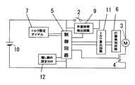
以下、本発明を添付図面に示す実施形態に基いて説明すると、図2は本発明に係るインパクト回転工具の一例をブロック図で示しており、図中2は動作指示用のメインスイッチ、3はモータ、4はモータのオンオフ制御用のスイッチング素子、5は制御回路、6は打撃検知回路、7は締め付けトルク設定用のトルク設定ダイヤル、9は作業時間検出回路、10は電源としての電池、11はトルク算出回路、12は増し締め設定スイッチであり、電池10とメインスイッチ2とモータ3とスイッチング素子4が直列に接続されており、これらに制御回路5が並列に接続されている。 Hereinafter, the present invention will be described based on an embodiment shown in the accompanying drawings. FIG. 2 is a block diagram showing an example of an impact rotary tool according to the present invention. In FIG. Motor, 4 is a switching element for on / off control of the motor, 5 is a control circuit, 6 is an impact detection circuit, 7 is a torque setting dial for setting a tightening torque, 9 is a work time detection circuit, 10 is a battery as a power source, 11 Is a torque calculation circuit, and 12 is a retightening setting switch. A
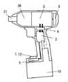
図3に構造的な概略を、図4に打撃による衝撃で締め付け作業を行う駆動機構30の一例を示す。モータ3の回転はサンギア34と遊星ギア32とインターナルギア33とからなる遊星機構で構成された減速部によって遊星ギア32を軸35で支持している駆動軸36に伝達される。駆動軸36の外周には鋼球38とカム溝39とによるカム機構を介してハンマー40が配設されており、ばね37によって前方へと付勢されている上記ハンマー40は、出力軸31が備えるアンビルと係合する係合部を備えている。 FIG. 3 shows a structural outline, and FIG. 4 shows an example of a
出力軸31に負荷がかかっていない時には、モータ3による駆動でハンマー40と出力軸31とは一体に回転するが、出力軸31に所定値以上の負荷がかかった時には、ハンマー40がばね37に抗して後退し、アンビルとの係合が外れた次点でハンマー40が回転しながら前進してアンビル(出力軸31)に回転方向の打撃衝撃を与え、出力軸31を回転させる。 When no load is applied to the
上記打撃の検知のための打撃検知回路6は、マイクや加速度センサーのような打撃自体を検知するものを用いることができるほか、打撃毎のアンビルの回転角を検出するものであってもよい。As the
トルク算出回路11は、打撃数Nに基づいて締め付けトルクT1を算出するものである場合、 When the

で推定することができる。打撃毎の出力軸31の回転角θを検出するものである場合、打撃毎のモータ3の回転量をΔn、モータ3から出力軸31までの減速比をη、モータの回転速度をωとすると、締め付けトルクT2は Can be estimated. In the case of detecting the rotation angle θ of the
で算出することができる。Can be calculated.
作業時間検出回路9は、メインスイッチ2と並列に接続されてメインスイッチのオン時間及びオフ時間を測定するものであるが、これは必ずしも必要ではない。 The work
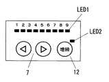
トルク設定ダイヤル7は、図5に示すようなダイヤル式のほか、図6に示すようなLED表示のレベルメータLED1とアップダウンスイッチとからなるもの等であってもよい。 The
そして増し締め設定スイッチ12は図5に示すようなスライドスイッチや、図6に示すようなボタン式のスイッチと増し締めモード表示用の発光表示部LED2などで構成することができる。 The additional
このインパクト回転工具においては、通常は非増し締めモード(通常モード)で作業を行うものであり、この場合、図1に示すようにメインスイッチ2をオンとすればモータ3が始動し、打撃動作を開始する。そしてトルク算出回路11で算出されるトルクがトルク設定ダイヤル7で設定されたトルク値になれば、制御回路5はメインスイッチ2のオン状態であってもスイッチング素子4をオフとすることでモータ3を停止させる。図中αはこのトルク制御による締め付け作業を示している。 In this impact rotary tool, the work is normally performed in the non-retightening mode (normal mode). In this case, as shown in FIG. 1, when the
このモータ3のオフにより作業者がメインスイッチ2をオフとした後、増し締めを行う必要があると判断したならば、増し締め設定スイッチ12の操作で増し締めモードに移行し、再度メインスイッチ2をオンとすればよい。この時制御回路5は通常モードとは異なった増し締め動作βを行う。 If the operator determines that it is necessary to perform additional tightening after the
この増し締め動作βとしては、所定の打撃数だけ打撃を行う、所定の時間だけ打撃を行う、モータ3の回転数が所定回転数になるまで打撃を行う、出力軸31を所定の回転角だけ回転させる等のいずれであってもよいが、所定の打撃数だけ打撃を行うものである場合、この打撃数の打撃を完了すれば、メインスイッチ2のオン状態にかかわらずモータ3を停止させる。この後、いったんメインスイッチ2がオフされ、再度メインスイッチ2がオンとなれば、増し締めモードが解除されていない限り、再度増し締め動作βを行う。 As this additional tightening operation β, hitting is performed for a predetermined number of hits, hitting is performed for a predetermined time, hitting is performed until the number of rotations of the
増し締め動作βによる打撃動作における上記の所定の値は、トルク設定ダイヤル7で設定されたトルク値に応じた値とする。打撃数で増し締め管理を行う場合の一例を下表に示す。 The predetermined value in the striking operation by the retightening operation β is a value corresponding to the torque value set by the
図7に示すように、増し締め角度設定ダイヤル8を設けておき、増し締めモードにおいては増し締め角度設定ダイヤル8で設定された増し締め角度(打撃数や打撃時間であってもよい)だけ、増し締めでの打撃動作が行われるようにしてもよい。 As shown in FIG. 7, an additional tightening
このほか、連続した増し締め動作が所定回数以上連続して行われた場合は、トルク設定ダイヤル7で設定されているトルク設定値を自動的に1レベル上げて、次の通常作業のトルク設定を大きくするようにすることも好ましい。たとえば、下表でトルク設定の2レベル上に相当する推定トルク値となる増し締め動作が行われたならば、現在のトルク設定のレベルが低すぎるために増し締め動作を連続して行わなければならないと判断してトルク設定を1レベルだけ上のものに自動変更してしまうのである。増し締めモードでの増し締め動作の打撃量を自動的に1レベルだけ上のものに自動変更してもよい。 In addition, when the continuous tightening operation is continuously performed for a predetermined number of times or more, the torque setting value set with the
ところで、増し締め設定スイッチ12によって増し締めモードに移行させなければ増し締め動作が行えないということになれば、通常作業の次に連続して増し締め動作を行いたい場合、増し締め設定スイッチ12を操作する必要があり、これはこれで操作性に問題を有することになる。 By the way, if the additional tightening operation cannot be performed unless the additional
このために、ここでは前述の作業時間検出回路9を設けており、図8に示すように通常モードでの作業αが完了してモータ3がオフとなった後、作業者がいったんメインスイッチ2をオフとしてから再度メインスイッチ2をオンするまでの時間T1が所定時間T2より短ければ、増し締め設定スイッチ12が通常モードにあっても増し締めモードに自動移行して増し締め動作βを行うことができるようにしている。 For this purpose, the aforementioned work
2 メインスイッチ
3 モータ
5 制御手段
7 トルク設定手段
11 トルク算出部
12 増し締め設定部2
Claims (2)
Translated fromJapanese上記トルク算出部で算出された締め付けトルクが上記トルク設定手段で設定されたトルクに達したならば上記駆動源を自動停止させる通常モードのほかに、通常モードで締め付けられた被締め付け部材に対してさらに所定の打撃を加えて増し締めを行う増し締めモードを備えるとともに、上記両モードを切り換える増し締め設定部を備えており、上記制御手段は上記増し締めモード時に行う増し締め動作として、上記トルク設定手段で設定されている通常モード用のトルクに応じた所定の打撃を加える動作を行わせるものであることを特徴とするインパクト回転工具。A drive mechanism that performs tightening work with impact force by impact, a motor as a drive source of the drive mechanism, torque setting means for setting a tightening torque, a torque calculation unit that calculates a tightening torque during a tightening operation, and an operation An impact rotary tool comprising an instruction main switch, and a control means for controlling on / off of the motor based on the main switch, the output of the torque calculation unit, and the torque set by the torque setting means,
In addition to the normal mode in which the drive source is automatically stopped if the tightening torque calculated by the torque calculation unit reaches the torque set by the torque setting means, the tightening member is tightened in the normal mode. with further comprising a tightening mode for tightening by adding a predetermined strike includesa retightening setting unitfor switching the twomodes, said control meansas a tightening operation performed onthe retightenmode, the torque setting An impact rotary tool characterized in that itperforms an operation of applying a predetermined hit in accordance with the normal mode torque set by the means .
Priority Applications (4)
| Application Number | Priority Date | Filing Date | Title |
|---|---|---|---|
| JP2004142844AJP4400303B2 (en) | 2004-05-12 | 2004-05-12 | Impact rotary tool |
| CNB2005100688046ACN100450725C (en) | 2004-05-12 | 2005-05-11 | Rotary impact tool |
| US11/126,351US20050263305A1 (en) | 2004-05-12 | 2005-05-11 | Rotary impact tool |
| EP05252923AEP1595649B1 (en) | 2004-05-12 | 2005-05-12 | Rotary impact tool |
Applications Claiming Priority (1)
| Application Number | Priority Date | Filing Date | Title |
|---|---|---|---|
| JP2004142844AJP4400303B2 (en) | 2004-05-12 | 2004-05-12 | Impact rotary tool |
Publications (2)
| Publication Number | Publication Date |
|---|---|
| JP2005324264A JP2005324264A (en) | 2005-11-24 |
| JP4400303B2true JP4400303B2 (en) | 2010-01-20 |
Family
ID=34941270
Family Applications (1)
| Application Number | Title | Priority Date | Filing Date |
|---|---|---|---|
| JP2004142844AExpired - Fee RelatedJP4400303B2 (en) | 2004-05-12 | 2004-05-12 | Impact rotary tool |
Country Status (4)
| Country | Link |
|---|---|
| US (1) | US20050263305A1 (en) |
| EP (1) | EP1595649B1 (en) |
| JP (1) | JP4400303B2 (en) |
| CN (1) | CN100450725C (en) |
Families Citing this family (63)
| Publication number | Priority date | Publication date | Assignee | Title |
|---|---|---|---|---|
| JP4400519B2 (en)* | 2005-06-30 | 2010-01-20 | パナソニック電工株式会社 | Impact rotary tool |
| JP4998079B2 (en)* | 2007-05-11 | 2012-08-15 | 日立工機株式会社 | Electric tool |
| US7806198B2 (en) | 2007-06-15 | 2010-10-05 | Black & Decker Inc. | Hybrid impact tool |
| JP5057145B2 (en)* | 2007-09-24 | 2012-10-24 | 日立工機株式会社 | Electric tool |
| EP2110921B1 (en) | 2008-04-14 | 2013-06-19 | Stanley Black & Decker, Inc. | Battery management system for a cordless tool |
| JP5112956B2 (en)* | 2008-05-30 | 2013-01-09 | 株式会社マキタ | Rechargeable power tool |
| US8269612B2 (en) | 2008-07-10 | 2012-09-18 | Black & Decker Inc. | Communication protocol for remotely controlled laser devices |
| EP2318636B1 (en) | 2008-08-06 | 2019-01-09 | Milwaukee Electric Tool Corporation | Precision torque tool |
| US9193053B2 (en) | 2008-09-25 | 2015-11-24 | Black & Decker Inc. | Hybrid impact tool |
| US8631880B2 (en)* | 2009-04-30 | 2014-01-21 | Black & Decker Inc. | Power tool with impact mechanism |
| JP5426978B2 (en)* | 2009-09-18 | 2014-02-26 | パナソニック株式会社 | Electric tool |
| US8460153B2 (en)* | 2009-12-23 | 2013-06-11 | Black & Decker Inc. | Hybrid impact tool with two-speed transmission |
| US8584770B2 (en) | 2010-03-23 | 2013-11-19 | Black & Decker Inc. | Spindle bearing arrangement for a power tool |
| DE102010029267A1 (en)* | 2010-05-25 | 2011-12-01 | Robert Bosch Gmbh | Power tool, in particular drill driver |
| DE102010030071A1 (en)* | 2010-06-15 | 2011-12-15 | Hilti Aktiengesellschaft | driving- |
| DE102010030118A1 (en) | 2010-06-15 | 2011-12-15 | Hilti Aktiengesellschaft | driving- |
| DE102010030065A1 (en) | 2010-06-15 | 2011-12-15 | Hilti Aktiengesellschaft | driving- |
| DE102010030098A1 (en) | 2010-06-15 | 2011-12-15 | Hilti Aktiengesellschaft | driving- |
| JP5486435B2 (en)* | 2010-08-17 | 2014-05-07 | パナソニック株式会社 | Impact rotary tool |
| WO2012061176A2 (en) | 2010-11-04 | 2012-05-10 | Milwaukee Electric Tool Corporation | Impact tool with adjustable clutch |
| DE102011005079A1 (en)* | 2011-03-04 | 2012-09-06 | Hilti Aktiengesellschaft | Setting method for an expansion anchor and impact wrench for setting a spreading anchor |
| JP5784473B2 (en)* | 2011-11-30 | 2015-09-24 | 株式会社マキタ | Rotating hammer tool |
| US9908182B2 (en) | 2012-01-30 | 2018-03-06 | Black & Decker Inc. | Remote programming of a power tool |
| CN103286727B (en)* | 2012-03-02 | 2015-06-10 | 南京德朔实业有限公司 | Impact wrench capable of adjusting twisting force |
| US9193055B2 (en) | 2012-04-13 | 2015-11-24 | Black & Decker Inc. | Electronic clutch for power tool |
| DE102012209446A1 (en)* | 2012-06-05 | 2013-12-05 | Robert Bosch Gmbh | Hand machine tool device |
| US8919456B2 (en) | 2012-06-08 | 2014-12-30 | Black & Decker Inc. | Fastener setting algorithm for drill driver |
| US20130327552A1 (en) | 2012-06-08 | 2013-12-12 | Black & Decker Inc. | Power tool having multiple operating modes |
| JP2014069264A (en)* | 2012-09-28 | 2014-04-21 | Hitachi Koki Co Ltd | Electric power tool |
| EP2926952A4 (en)* | 2012-11-29 | 2016-08-03 | Hitachi Koki Kk | PERCUSSION TOOL |
| JP2014172163A (en)* | 2013-03-13 | 2014-09-22 | Panasonic Corp | Electric tool |
| JP5579902B2 (en)* | 2013-06-04 | 2014-08-27 | 株式会社マキタ | Electric tool |
| CN104516367B (en)* | 2013-09-26 | 2017-02-22 | 南京德朔实业有限公司 | Electric tool and threaded piece fastening degree control method |
| JP6245943B2 (en)* | 2013-10-31 | 2017-12-13 | Tone株式会社 | Fastening device |
| DE102013222550B4 (en) | 2013-11-06 | 2024-12-19 | Robert Bosch Gmbh | hand tool machine |
| JP6304533B2 (en) | 2014-03-04 | 2018-04-04 | パナソニックIpマネジメント株式会社 | Impact rotary tool |
| US9893384B2 (en) | 2014-05-18 | 2018-02-13 | Black & Decker Inc. | Transport system for convertible battery pack |
| CN108616154B (en) | 2014-05-18 | 2021-09-14 | 百得有限公司 | Electric tool system |
| EP2985117A1 (en)* | 2014-08-12 | 2016-02-17 | HILTI Aktiengesellschaft | Optimised setting procedure for an expansible anchor |
| EP2985118A1 (en)* | 2014-08-12 | 2016-02-17 | HILTI Aktiengesellschaft | Optimised setting procedure for an expansible anchor |
| CN105751133A (en)* | 2014-12-18 | 2016-07-13 | 苏州博来喜电器有限公司 | Impact wrench |
| WO2016196984A1 (en) | 2015-06-05 | 2016-12-08 | Ingersoll-Rand Company | Power tools with user-selectable operational modes |
| US11260517B2 (en) | 2015-06-05 | 2022-03-01 | Ingersoll-Rand Industrial U.S., Inc. | Power tool housings |
| CN107635725B (en) | 2015-06-05 | 2019-11-12 | 英古所连公司 | Lighting system for power tool |
| WO2016196918A1 (en) | 2015-06-05 | 2016-12-08 | Ingersoll-Rand Company | Power tool user interfaces |
| WO2016196891A1 (en) | 2015-06-05 | 2016-12-08 | Ingersoll-Rand Company | Power tool user interfaces |
| WO2016196979A1 (en) | 2015-06-05 | 2016-12-08 | Ingersoll-Rand Company | Impact tools with ring gear alignment features |
| JP6621013B2 (en)* | 2015-10-20 | 2019-12-18 | 勝行 戸津 | Method and system for determining whether screw tightening is good or bad |
| JP6400636B2 (en)* | 2015-11-26 | 2018-10-03 | 株式会社マキタ | Electric tool |
| US10478950B2 (en) | 2015-11-26 | 2019-11-19 | Makita Corporation | Power tool |
| US10646982B2 (en) | 2015-12-17 | 2020-05-12 | Milwaukee Electric Tool Corporation | System and method for configuring a power tool with an impact mechanism |
| EP3560062A4 (en) | 2016-12-23 | 2020-06-24 | Black & Decker Inc. | CORDLESS ELECTRIC TOOL SYSTEM |
| JP6916060B2 (en)* | 2017-08-09 | 2021-08-11 | 株式会社マキタ | Electric work machine |
| JP6901346B2 (en) | 2017-08-09 | 2021-07-14 | 株式会社マキタ | Electric work machine |
| EP3501740A1 (en)* | 2017-12-20 | 2019-06-26 | HILTI Aktiengesellschaft | Setting method for threaded connection by means of impact wrench |
| JP7210291B2 (en)* | 2019-01-10 | 2023-01-23 | 株式会社マキタ | electric driver drill |
| US11673240B2 (en) | 2019-08-06 | 2023-06-13 | Makita Corporation | Driver-drill |
| JP7320419B2 (en) | 2019-09-27 | 2023-08-03 | 株式会社マキタ | rotary impact tool |
| JP7386027B2 (en)* | 2019-09-27 | 2023-11-24 | 株式会社マキタ | rotary impact tool |
| CN115515755A (en)* | 2020-05-01 | 2022-12-23 | 米沃奇电动工具公司 | Rotary impact tool |
| EP4263138A1 (en) | 2020-12-18 | 2023-10-25 | Black & Decker Inc. | Impact tools and control modes |
| CN118715087A (en)* | 2022-03-04 | 2024-09-27 | 工机控股株式会社 | Working machine |
| EP4494815A1 (en)* | 2023-07-18 | 2025-01-22 | Nanjing Chervon Industry Co., Ltd. | Impact tool |
Family Cites Families (21)
| Publication number | Priority date | Publication date | Assignee | Title |
|---|---|---|---|---|
| US3780603A (en)* | 1972-05-11 | 1973-12-25 | Wolff Sales Eng Co | Impact control for impact wrenches |
| US4316512A (en)* | 1979-04-04 | 1982-02-23 | Sps Technologies, Inc. | Impact wrench |
| GB2232372A (en)* | 1989-05-25 | 1990-12-12 | Black & Decker Inc | Improvements in or relating to power tools |
| JP2943457B2 (en)* | 1991-09-30 | 1999-08-30 | トヨタ自動車株式会社 | Nutrunner |
| US5402688A (en)* | 1993-03-17 | 1995-04-04 | Sumitomo Metal Industries, Ltd. | Method and apparatus for determining the tightened condition of a pipe joint |
| JP3000185B2 (en)* | 1993-04-21 | 2000-01-17 | 株式会社山崎歯車製作所 | Bolt fastening method using impact wrench |
| GB9320181D0 (en)* | 1993-09-30 | 1993-11-17 | Black & Decker Inc | Improvements in and relating to power tools |
| JPH07100772A (en)* | 1993-10-01 | 1995-04-18 | Ricoh Co Ltd | Rotary power tools |
| DE19503524A1 (en)* | 1995-02-03 | 1996-08-08 | Bosch Gmbh Robert | Impulse screwdriver and method for tightening a screw connection using the impulse screwdriver |
| JP3514034B2 (en)* | 1996-05-10 | 2004-03-31 | 日立工機株式会社 | Shear wrench |
| WO2000054939A1 (en)* | 1999-03-16 | 2000-09-21 | Kuken Co., Ltd. | Reading method of screw rotation angle of hand-held impact wrench, hand-vibration detection method, tightening evaluation method and control method of hand-held power screw loosening tool |
| JP3906606B2 (en)* | 1999-06-11 | 2007-04-18 | 松下電工株式会社 | Impact rotary tool |
| JP2001129767A (en)* | 1999-10-29 | 2001-05-15 | Matsushita Electric Works Ltd | Impact rotation tool |
| EP1769887B1 (en)* | 2000-03-16 | 2008-07-30 | Makita Corporation | Power tools |
| JP3456949B2 (en)* | 2000-06-19 | 2003-10-14 | 株式会社エスティック | Method and apparatus for controlling screw tightening device |
| EP1207016B1 (en)* | 2000-11-17 | 2009-01-07 | Makita Corporation | Impact power tools |
| JP3886818B2 (en)* | 2002-02-07 | 2007-02-28 | 株式会社マキタ | Tightening tool |
| JP2004291138A (en)* | 2003-03-26 | 2004-10-21 | Matsushita Electric Works Ltd | Magnetic impact tool |
| JP4093145B2 (en)* | 2003-08-26 | 2008-06-04 | 松下電工株式会社 | Tightening tool |
| JP2005118910A (en)* | 2003-10-14 | 2005-05-12 | Matsushita Electric Works Ltd | Impact rotary tool |
| JP2005144564A (en)* | 2003-11-11 | 2005-06-09 | Matsushita Electric Works Ltd | Portable electric tool |
- 2004
- 2004-05-12JPJP2004142844Apatent/JP4400303B2/ennot_activeExpired - Fee Related
- 2005
- 2005-05-11CNCNB2005100688046Apatent/CN100450725C/ennot_activeExpired - Fee Related
- 2005-05-11USUS11/126,351patent/US20050263305A1/ennot_activeAbandoned
- 2005-05-12EPEP05252923Apatent/EP1595649B1/ennot_activeExpired - Lifetime
Also Published As
| Publication number | Publication date |
|---|---|
| EP1595649A3 (en) | 2007-05-02 |
| US20050263305A1 (en) | 2005-12-01 |
| EP1595649A2 (en) | 2005-11-16 |
| CN1695899A (en) | 2005-11-16 |
| JP2005324264A (en) | 2005-11-24 |
| EP1595649B1 (en) | 2013-03-13 |
| CN100450725C (en) | 2009-01-14 |
Similar Documents
| Publication | Publication Date | Title |
|---|---|---|
| JP4400303B2 (en) | Impact rotary tool | |
| JP4211675B2 (en) | Impact rotary tool | |
| US9296095B2 (en) | Rotary tool | |
| JP4412377B2 (en) | Impact rotary tool | |
| JP4211676B2 (en) | Impact rotary tool | |
| JP3903976B2 (en) | Tightening tool | |
| JP5914841B2 (en) | Electric tool | |
| CN102971113B (en) | Impact tool | |
| JP5800761B2 (en) | Electric tool | |
| JP2005118910A (en) | Impact rotary tool | |
| CN103038026B (en) | Screw tightening tool | |
| US20130062086A1 (en) | Power tool | |
| US20230321796A1 (en) | Power tool with sheet metal fastener mode | |
| JP2007062012A (en) | Rotary tool | |
| JP2020049637A (en) | Electric tool | |
| JP2009083039A (en) | Electric tool | |
| JP3130851U (en) | Handy type clamping machine with reaction force receiver | |
| JP2008213089A (en) | Rotary tool | |
| JP5053882B2 (en) | Impact rotary tool | |
| JP2024043261A (en) | Power tools and motor control methods for power tools | |
| JP5716898B2 (en) | Electric tool | |
| JP2011245583A (en) | Power tool | |
| JP2009083041A (en) | Impact rotary tool | |
| JP5958817B2 (en) | Electric tool | |
| JP2025006659A (en) | Work equipment |
Legal Events
| Date | Code | Title | Description |
|---|---|---|---|
| A131 | Notification of reasons for refusal | Free format text:JAPANESE INTERMEDIATE CODE: A131 Effective date:20080212 | |
| A521 | Written amendment | Free format text:JAPANESE INTERMEDIATE CODE: A523 Effective date:20080414 | |
| A131 | Notification of reasons for refusal | Free format text:JAPANESE INTERMEDIATE CODE: A131 Effective date:20081007 | |
| A521 | Written amendment | Free format text:JAPANESE INTERMEDIATE CODE: A523 Effective date:20081208 | |
| A02 | Decision of refusal | Free format text:JAPANESE INTERMEDIATE CODE: A02 Effective date:20090407 | |
| A521 | Written amendment | Free format text:JAPANESE INTERMEDIATE CODE: A523 Effective date:20090707 | |
| A911 | Transfer to examiner for re-examination before appeal (zenchi) | Free format text:JAPANESE INTERMEDIATE CODE: A911 Effective date:20090714 | |
| TRDD | Decision of grant or rejection written | ||
| A01 | Written decision to grant a patent or to grant a registration (utility model) | Free format text:JAPANESE INTERMEDIATE CODE: A01 Effective date:20091006 | |
| A01 | Written decision to grant a patent or to grant a registration (utility model) | Free format text:JAPANESE INTERMEDIATE CODE: A01 | |
| A61 | First payment of annual fees (during grant procedure) | Free format text:JAPANESE INTERMEDIATE CODE: A61 Effective date:20091019 | |
| FPAY | Renewal fee payment (event date is renewal date of database) | Free format text:PAYMENT UNTIL: 20121106 Year of fee payment:3 | |
| FPAY | Renewal fee payment (event date is renewal date of database) | Free format text:PAYMENT UNTIL: 20121106 Year of fee payment:3 | |
| FPAY | Renewal fee payment (event date is renewal date of database) | Free format text:PAYMENT UNTIL: 20131106 Year of fee payment:4 | |
| LAPS | Cancellation because of no payment of annual fees |