JP4400273B2 - Combustor and reactor - Google Patents
Combustor and reactorDownload PDFInfo
- Publication number
- JP4400273B2 JP4400273B2JP2004085037AJP2004085037AJP4400273B2JP 4400273 B2JP4400273 B2JP 4400273B2JP 2004085037 AJP2004085037 AJP 2004085037AJP 2004085037 AJP2004085037 AJP 2004085037AJP 4400273 B2JP4400273 B2JP 4400273B2
- Authority
- JP
- Japan
- Prior art keywords
- fuel
- hydrogen
- path
- combustion
- microchannel
- Prior art date
- Legal status (The legal status is an assumption and is not a legal conclusion. Google has not performed a legal analysis and makes no representation as to the accuracy of the status listed.)
- Expired - Fee Related
Links
Images


Classifications
- Y—GENERAL TAGGING OF NEW TECHNOLOGICAL DEVELOPMENTS; GENERAL TAGGING OF CROSS-SECTIONAL TECHNOLOGIES SPANNING OVER SEVERAL SECTIONS OF THE IPC; TECHNICAL SUBJECTS COVERED BY FORMER USPC CROSS-REFERENCE ART COLLECTIONS [XRACs] AND DIGESTS
- Y02—TECHNOLOGIES OR APPLICATIONS FOR MITIGATION OR ADAPTATION AGAINST CLIMATE CHANGE
- Y02E—REDUCTION OF GREENHOUSE GAS [GHG] EMISSIONS, RELATED TO ENERGY GENERATION, TRANSMISSION OR DISTRIBUTION
- Y02E60/00—Enabling technologies; Technologies with a potential or indirect contribution to GHG emissions mitigation
- Y02E60/30—Hydrogen technology
- Y02E60/50—Fuel cells
Landscapes
- Hydrogen, Water And Hydrids (AREA)
- Fuel Cell (AREA)
Description
Translated fromJapanese本発明は、燃料と水素を燃焼させて燃焼熱を発する燃焼器に関するとともに、燃料と水素を燃焼させてその燃焼熱により反応を行う反応装置に関する。 The present invention relates to a combustor that burns fuel and hydrogen to generate combustion heat, and also relates to a reaction apparatus that burns fuel and hydrogen and reacts with the combustion heat.
近年では、高いエネルギー利用効率を実現できる燃料電池についての研究・開発が盛んにおこなわれている。燃料電池は、燃料と大気中の酸素とを電気化学的に反応させて化学エネルギーから電気エネルギーを直接取り出すものであり、将来性に富む有望な電源であると位置付けられている。燃料電池に用いる燃料としては水素が挙げられるが、常温で気体であることによる取り扱い・貯蔵に問題がある。そこで、アルコール類及びガソリンといった液体燃料を用いれば液体燃料を貯蔵するためのシステムが比較的小型になるが、水を加えた燃料を改質させることによって発電に必要な水素を生成する必要がある。 In recent years, research and development have been actively conducted on fuel cells that can achieve high energy use efficiency. A fuel cell is one that takes out electric energy directly from chemical energy by electrochemically reacting fuel and oxygen in the atmosphere, and is regarded as a promising power source with a great potential. The fuel used in the fuel cell includes hydrogen, but there is a problem in handling and storage due to being a gas at room temperature. Therefore, when liquid fuels such as alcohols and gasoline are used, the system for storing the liquid fuel becomes relatively small. However, it is necessary to generate hydrogen necessary for power generation by reforming the fuel to which water is added. .
燃料と水から水素を生成するためには、蒸発器により燃料と水を気化させた後、蒸発器から供給された燃料と水の混合気を改質反応器により水素に改質する。改質反応器を加熱するために、改質反応器の加熱室に、蒸発器を加熱する燃焼器からの燃焼ガスを供給して燃焼ガスの未燃焼成分を燃焼したり、燃料電池スタックのオフガスを供給して燃焼させたりすることが行われている(例えば、特許文献1参照)。
このように特許文献1の加熱室では、燃焼ガスの未燃焼成分を燃焼するばかりではなく、水素分離膜で水素と分離されたアノードオフガスを燃焼触媒で燃焼させていることによって改質原料の未反応分が発生しないことになっている。つまりアノードオフガスは改質反応器で改質されなかった燃料成分を有し、この燃焼成分は燃焼器で燃焼する燃料成分と一致することになるので加熱室で燃焼される成分は単一種となる。
ところで、改質された水素は化学反応を起こし燃料電池のアノード極とカソード極の間をプロトンとして移動する際に電気を発生するが、一部の水素は上記化学反応しないまま残存することがある。水素を燃焼するのに適した燃焼触媒は、燃料を燃焼するのに適した燃焼触媒と組成成分比や組成成分自体が異なり、更には、水素の燃焼速度が、燃料の燃焼速度と異なる。この残存した水素を燃焼して得られた燃焼熱を改質器に供給しようとすると、特許文献1の加熱室では、十分水素が燃焼されなかったり、水素と燃料を同一箇所の同一種の燃焼触媒で燃焼させたりしているため、水素と燃料の両方を効率的に燃焼させることが難しい。Thus, in the heating chamber of Patent Document 1, not only the unburned components of the combustion gas are combusted, but also the anode off-gas separated from the hydrogen by the hydrogen separation membrane is burned by the combustion catalyst, so No reaction is expected to occur. That is, the anode off-gas has a fuel component that has not been reformed in the reforming reactor, and this combustion component coincides with the fuel component that burns in the combustor, so that the component burned in the heating chamber is a single species. .
By the way, the reformed hydrogen causes a chemical reaction and generates electricity when moving between the anode and cathode of the fuel cell as protons, but some hydrogen may remain without the chemical reaction. . The combustion catalyst suitable for burning hydrogen is different from the combustion catalyst suitable for burning fuel in the composition component ratio and the composition component itself, and further, the hydrogen combustion rate is different from the fuel combustion rate. If an attempt is made to supply combustion heat obtained by burning the remaining hydrogen to the reformer, in the heating chamber of Patent Document 1, hydrogen is not sufficiently burned, or hydrogen and fuel are burned of the same type at the same location. Since it is burned with a catalyst, it is difficult to burn both hydrogen and fuel efficiently.
そこで、本発明は、上記のような問題点を解決しようとしてなされたものであり、水素と燃料の両方を効率的に燃焼させることを目的とする。 Therefore, the present invention has been made to solve the above-described problems, and an object thereof is to efficiently burn both hydrogen and fuel.
以上の課題を解決するために、本発明の燃焼器は、流路を形成した燃焼器本体と、前記流路の一部に形成された水素用燃焼触媒と、前記流路の別の一部に形成された燃料用燃焼触媒と、を備え、前記流路は、燃料を取り込む燃料取込口から合流部までの燃料経路と、水素を取り込む水素取込口から前記合流部までの水素経路と、前記合流部から排出口までの混合経路とからなり、前記水素用燃焼触媒を前記水素経路に形成し、前記燃料用燃焼触媒を前記混合経路と前記燃料経路とのうちの少なくとも一方に形成したことを特徴とする。In order to solve the above problems, a combustor according to thepresent invention includes a combustor body having a flow path, a hydrogen combustion catalyst formed in a part of the flow path, and another part of the flow path. A fuel combustion catalyst formed on the fuelflow path, wherein the flow path includes a fuel path from a fuel intake port for taking in the fuel to the junction, and a hydrogen path from the hydrogen intake port for taking in the hydrogen to the junction. The hydrogen combustion catalyst is formed in the hydrogen path, and the fuel combustion catalyst is formed in at least one of the mixing path and the fuel path. It is characterized by that.
本発明によれば、水素用燃焼触媒及び燃料用燃焼触媒を流路の別々の部分に形成したので、水素と燃料を流路に流した場合に、水素用燃焼触媒において水素が効率よく燃焼し、燃料用燃焼触媒において燃料が効率よく燃焼する。そのため、流路に水素と燃料を流しても、水素と燃料の両方を効率的に燃焼させることができる。さらに、水素取込口から取り込まれた水素が水素経路を流れている時に水素が水素用燃焼触媒により燃焼する。一方、燃料取込口から取り込まれた燃料が燃料経路又は混合経路を流れている時に燃料が燃焼する。また、水素が水素経路を流れている時は水素に燃料が混合されていないので、水素が効率よく燃焼する。燃料経路に燃料用燃焼触媒が形成されている場合には、燃料が燃料経路を流れている時は燃料に水素が混合されていないので、燃料が効率よく燃焼する。一方、混合経路に燃料用燃焼触媒が形成されている場合には、水素は燃焼して水に化学変化した状態で、合流部で燃料の混合をするから、燃料が混合経路を流れている時は燃料に水素自体が混合されていないから、燃料が効率よく燃焼する。このように、水素と燃料を別々に燃焼させているので、水素と燃料の両方を効率的に燃焼させることができる。According to thepresent invention, since the hydrogen combustion catalyst and the fuel combustion catalyst are formed in separate parts of the flow path, when hydrogen and fuel are flowed through the flow path, hydrogen is efficiently burned in the hydrogen combustion catalyst. The fuel burns efficiently in the fuel combustion catalyst. Therefore, both hydrogen and fuel can be efficiently burned even if hydrogen and fuel are passed through the flow path.Furthermore, when the hydrogen taken in from the hydrogen intake port flows through the hydrogen path, the hydrogen burns by the hydrogen combustion catalyst. On the other hand, the fuel burns when the fuel taken in from the fuel intake port flows through the fuel path or the mixing path. In addition, when hydrogen is flowing through the hydrogen path, fuel is not mixed with hydrogen, so that hydrogen burns efficiently. When the fuel combustion catalyst is formed in the fuel path, when the fuel flows through the fuel path, the fuel is burned efficiently because hydrogen is not mixed with the fuel. On the other hand, when a fuel combustion catalyst is formed in the mixing path, hydrogen is burned and chemically changed to water, and the fuel is mixed at the junction, so when the fuel is flowing through the mixing path Since the fuel does not contain hydrogen itself, the fuel burns efficiently. Thus, since hydrogen and fuel are burned separately, both hydrogen and fuel can be burned efficiently.
また、空気取込口から流路に空気が取り込まれ、空気が燃料や水素と混合し、水素や燃料を燃焼させることができる。Further , air is taken into the flow path fromthe air intake port, and the air can be mixed with fuel and hydrogen to burn the hydrogen and fuel.
また、燃料や水素の燃焼熱が反応器に伝播し、反応器において燃料と水の反応が効率よく起こる。
なお、反応器における燃料と水の反応とは、化学変化を伴う化学反応のみならず、状態変化を伴う反応も含む意味である。Also, the combustion heat of fuel or hydrogen propagates to the reactor, and the reaction between fuel and water occurs efficiently in the reactor.
The reaction of fuel and water in the reactor means not only a chemical reaction accompanied by a chemical change but also a reaction accompanied by a state change.
本発明によれば、燃料と水素を別々に燃焼させることができ、水素と燃料の両方を効率的に燃焼させることができる。 According to the present invention, fuel and hydrogen can be burned separately, and both hydrogen and fuel can be burned efficiently.
以下に、本発明を実施するための最良の形態について図面を用いて説明する。但し、以下に述べる実施形態には、本発明を実施するために技術的に好ましい種々の限定が付されているが、発明の範囲を以下の実施形態及び図示例に限定するものではない。 The best mode for carrying out the present invention will be described below with reference to the drawings. However, although various technically preferable limitations for implementing the present invention are given to the embodiments described below, the scope of the invention is not limited to the following embodiments and illustrated examples.
〔第1の実施の形態〕
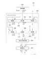
図1は、発電装置1のブロック図である。
発電装置1は、燃料と水を貯留した燃料容器2と、燃料容器2から供給された燃料と水から水素を生成する超小型反応炉であるマイクロリアクタ3と、マイクロリアクタ3で生成された水素の電気化学反応により電気エネルギーを生成する燃料電池4と、を備える。[First Embodiment]
FIG. 1 is a block diagram of the power generation device 1.
The power generation apparatus 1 includes a
発電装置1は、デジタルカメラ、携帯電話機、ノート型パーソナルコンピュータ、腕時計、PDA、電子計算機、その他の電子機器に搭載されたものである。特に、マイクロリアクタ3及び燃料電池4は電子機器本体に内蔵され、燃料容器2は電子機器本体に対して着脱可能に設けられている。燃料容器2が電子機器本体に装着された場合、燃料容器2内の燃料及び水がポンプによってマイクロリアクタ3に供給されるようになっている。 The power generation device 1 is mounted on a digital camera, a mobile phone, a notebook personal computer, a wristwatch, a PDA, an electronic calculator, or other electronic devices. In particular, the
燃料容器2内に貯留された燃料は、メタノール、エタノール等のアルコール類やガソリンといった水素元素を含む化合物が適用可能である。本実施形態では、燃料としてメタノールを用いている。燃料と水は別々で燃料容器2に貯蔵されても良いし、混合された状態で燃料容器2に貯蔵されても良い。 As the fuel stored in the
マイクロリアクタ3は、燃料容器2から供給された燃料及び燃料電池4から供給された水素を酸化させることにより燃焼熱を発する燃焼器5,6と、燃料容器2から供給された燃料と水を気化させる反応器としての気化器7と、化学反応式(1)、(2)に示すように気化器7から供給された燃料と水の混合気を水素に改質する反応器としての改質器8と、化学反応式(3)に示すように改質器8で生成された生成物の混合気中の一酸化炭素を酸化させることによって一酸化炭素を除去する一酸化炭素除去器9と、を備える。なお、本発明に係る燃焼器を燃焼器5,6に適用している。
CH3OH+H2O→3H2+CO2 …(1)
2CH3OH+H2O→5H2+CO+CO2 …(2)
2CO+O2→2CO2 …(3)
気化器7は、燃料と水を効率的に気化するために100〜120℃に加熱することが好ましく、改質器8は、上記改質反応を効率的に引き起こすために250℃以上に加熱することが好ましく、一酸化炭素除去器9は、上記一酸化炭素除去反応を効率的に引き起こすために150〜180℃に加熱することが好ましい。The
CH3 OH + H2 O → 3H2 + CO2 (1)
2CH3 OH + H2 O → 5H2 + CO + CO2 (2)
2CO + O2 → 2CO2 (3)
The
改質器8及び燃焼器6は一体化して設けられており、燃焼器6で発生した燃焼熱が改質器8に伝導して改質器8における反応に用いられ、気化器7及び燃焼器5は一体化して設けられており、燃焼器5で発生した燃焼熱が気化器7に伝導して気化器7における蒸発に用いられるよう設けられている。 The
なお、燃焼器5、6と燃料容器2との間に燃焼燃料用気化器を設け、燃料容器2から燃料が該気化器に供給され、その燃料が該気化器で気化し、気化した燃料が燃焼器5,6に供給されても良い。 In addition, a carburetor for combustion fuel is provided between the
燃料電池4は、触媒微粒子を担持した燃料極と、触媒微粒子を担持した酸素極と、燃料極と酸素極との間に介在されたフィルム状の固体高分子電解質膜と、を備える。燃料電池4の燃料極には、一酸化炭素除去器9から生成物の混合気が供給され、燃料電池4の酸素極には、外部から空気が供給される。燃料極においては、電気化学反応式(4)に示すように、混合気中の水素が燃料極の触媒微粒子の作用を受けて水素イオンと電子とに分離する。水素イオンは固体高分子電解質膜を通じて酸素極に伝導し、電子は燃料極により取り出される。酸素極においては、電気化学反応式(5)に示すように、酸素極に移動した電子と、空気中の酸素と、固体高分子電解質膜を通過した水素イオンとが反応し、水が生成される。
H2→2H++2e- …(4)
2H++1/2O2+2e-→H2O …(5)The
H2 → 2H+ + 2e− (4)
2H+ + 1 / 2O2 + 2e− → H2 O (5)
燃料電池4の燃料極では、効果的に発電させるために継続的に水素が供給されることになり、燃料極に水素が滞留している時間が制限されるため全ての水素が上記のように反応するわけではなく、反応しない水素もある。未反応の水素は二酸化炭素等の生成物とともに燃料極から排気されるが、燃料電池4の燃料極が流路を介して燃焼器5,6に通じており、排気された水素が燃焼器5,6に供給されるよう設けられている。 In the fuel electrode of the
燃料の燃焼に適した触媒の成分が水素の燃焼に適した触媒の成分と異なったり、燃料の燃焼反応速度が水素の燃焼反応速度と異なったりするため、燃焼器5,6は燃料の燃焼であっても水素の燃焼であっても不完全燃焼を抑えるよう設計されている。 The
図2、図3、図4を用いて、燃焼器6と改質器8を一体化した反応装置10について詳細に説明する。図2は、反応装置10の斜視図であり、図3は、図2の面IIIに沿った断面図であり、図4は、図3の面IVに沿った断面図である。 The
反応装置10はシリコン結晶、アルミニウム、ガラス、セラミック等の中から選択された一又は複数の材料で形成された三枚の基板11,12,13を備え、これら三枚の基板11〜13を積み重ねて接合したものが反応装置10の本体となる。ここで、燃焼器6の本体は、上側の上基板11と、挟持された中基板12とから構成され、改質器8の本体は、下側の下基板13と、中基板12とから構成され、中基板12が燃焼器6及び改質器8の両方に共通している。基板11〜13は合板であっても良いし、多層基板であっても良いし、単板であっても良い。 The
図3に示すように、下基板13における中基板12との接合面側(図3において下基板13の上面)には、葛折り状の溝が形成されており、この溝は下基板13と中基板12との接合前にサンドブラスト法等を施すことによって形成されたものである。この溝を覆うようにして下基板13を中基板12に接合することによって、溝が接合面に沿った葛折り状の反応用マイクロ流路14となる。反応用マイクロ流路14は一端部から他端部にかけて一様な幅、一様な深さを有しながら延在しており、その幅及び深さが2mm以下、望ましくは1.8mm以下が望ましい。この反応用マイクロ流路14は、改質器8の流路である。 As shown in FIG. 3, a twisted groove is formed on the side of the
図2に示すように、反応用マイクロ流路14の一端部が取込口17として下基板13の側面に面しており、反応用マイクロ流路14の他端部が排出口18として反対側の側面に面している。取込口17には管等を介して気化器7に接続され、気化器7で気化した燃料と水の混合気が取込口17から反応用マイクロ流路14に流入する。排出口18には管等を介して一酸化炭素除去器9に接続され、混合気が反応用マイクロ流路14から排出口18を通じて一酸化炭素除去器9に供給される。 As shown in FIG. 2, one end portion of the
反応用マイクロ流路14の壁面、特に下基板13に形成された溝の底及び側面には、改質用触媒16が形成されている。改質用触媒16は、メタノールと水を水素と二酸化炭素に改質する(上記化学反応式(1)参照)触媒であって、担体としてのアルミナに銅及び酸化亜鉛を担持させたCu/ZnO系触媒(Cu/ZnO/Al2O3)である。A reforming
図3に示すように、上基板11における中基板12との接合面側(図3において上基板11の下面)には、溝が形成されており、この溝は上基板11と中基板12との接合前にサンドブラスト法等を施すことによって形成されたものである。この溝を覆うようにして上基板11を中基板12に接合することによって、溝が接合面に沿った燃焼用マイクロ流路15となる。燃焼用マイクロ流路15は一様な幅、一様な深さを有し、その幅及び深さが2mm以下、望ましくは1.8mm以下が望ましい。この燃焼用マイクロ流路15は、燃焼器6の流路である。 As shown in FIG. 3, a groove is formed on the side of the
図4に示すように、燃焼用マイクロ流路15は分岐しており、5つの端部を有する。燃焼用マイクロ流路15の5つの端部のうち、第1端部〜第4端部がそれぞれ取込口19〜22として上基板11の側面に面しており、第5端部が排出口23として反対側の側面に面している。空気取込口19には管等を介して外部に通じており、空気(酸化剤として酸素を含む。)が空気取込口19から燃焼用マイクロ流路15に流入する。燃料取込口20には管等を介して燃料容器2に通じており、燃料容器2の燃料が燃料取込口20から燃焼用マイクロ流路15に流入する。水素取込口21には管等を介して燃料電池4の燃料極に通じており、燃料電池4の燃料極から水素等が水素取込口21から燃焼用マイクロ流路15に流入する。空気取込口22には管等を介して外部に通じており、外部の空気が空気取込口22から燃焼用マイクロ流路15に流入する。排出口23には管等を介して外部に通じており、生成物が燃焼用マイクロ流路15から排出口23を通じて外部に排出される。 As shown in FIG. 4, the
燃焼用マイクロ流路15の経路について説明する。合流部24においては、燃料取込口20から合流部24までの燃料経路25と、空気取込口19から合流部24までの空気経路26と、合流部24から合流部32までの燃料経路27とが合流している。合流部30においては、水素取込口21から合流部30までの水素経路29と、空気取込口22から合流部30までの空気経路28と、合流部30から合流部32までの水素経路31とが合流している。合流部32においては、合流部24から合流部32までの燃料経路27と、合流部30から合流部32までの水素経路31と、合流部32から排出口23までの混合経路33とが合流している。なお、燃焼用マイクロ流路15のうち、水素経路31及び混合経路33が葛折り状に形成されている。 The path of the
合流部30から合流部32までの水素経路31のうちその中間部(図4において塗りつぶした領域)の壁面には、水素用燃焼触媒34が形成され、合流部32から排出口23までの混合経路33の壁面には、燃料用燃焼触媒35が形成されている。水素用燃焼触媒34は、アルミナ(Al2O3)を担体として白金(Pt)を担持させたものであり、水素の酸化(燃焼)に適するよう白金の担持量が1wt%以下、好ましくは0.1〜0.5wt%が望ましい。燃料用燃焼触媒35は、アルミナを担体として白金を担持させたものであり、燃料(メタノール)の酸化に適するよう白金の担持量が3〜6wt%であるのが望ましい。このように水素用燃焼触媒34及び燃料用燃焼触媒35は互いに組成成分比が異なる。A
なお、合流部24から合流部32までの燃料経路27の壁面に、燃料燃焼用触媒が形成されても良い。また、燃料経路27に燃料用燃焼触媒が形成されている場合には、混合経路33に燃料用燃焼触媒35が形成されていなくても良い。即ち、燃料経路27と混合経路33の少なくとも一方に、燃料用燃焼触媒が形成されていれば良い。 A fuel combustion catalyst may be formed on the wall surface of the
図3に示すように、下基板13の下面には、所定形状にパターニングされた薄膜ヒータ36が形成されている。薄膜ヒータ36は、その電気的特性(例えば、抵抗率)が温度に依存する発熱抵抗体、発熱半導体等の電熱材料からなる。薄膜ヒータ36に電力を供給すれば、薄膜ヒータ36が発熱するが、薄膜ヒータ36の電気抵抗率は温度に依存するため薄膜ヒータ36の電流・電圧等を測定すれば、薄膜ヒータ36に接している改質器8の温度、すなわち、改質器8の反応用マイクロ流路14の温度が算出でき、改質器8での改質反応温度をモニタリングすることが可能となっている。なお、図2では、図を見やすくするために薄膜ヒータ36の図示を省略する。燃焼器6は、熱効率の観点から改質器8の改質反応の主たる熱源として利用され、薄膜ヒータ36は、改質器8が所定の温度になるように微調整するための補助熱源として利用される。特に発電装置1の発電初期時に迅速に改質器8を所定の温度に到達させたり、或いは燃焼器6が定常状態の燃焼を引き起こしたりするために薄膜ヒータ36の温度を制御することが好ましい。 As shown in FIG. 3, a
図1に示した気化器7と燃焼器5とからなる反応装置50も、反応装置10とほぼ同様に構成されているので、反応装置50については反応装置10のいずれかの部分と同一の部分に対して同一の符号を付し、同一の部分についての説明は省略する。異なる部分としては、反応装置10の場合、反応用マイクロ流路14の壁面に改質用触媒16が形成されているが、反応装置50の場合、反応用マイクロ流路14の壁面には触媒が形成されていない。更に、反応装置50の場合、反応用マイクロ流路14の取込口17が管を介して燃料容器2に接続され、反応用マイクロ流路14の排出口18は管を介して反応装置10つまり改質器8の取込口17に接続されている。なお、気化器7の反応用マイクロ流路14の壁面には、燃焼器5や薄膜ヒータ36等の熱を効率よく吸収し、放熱するために燃料や水に対して不活性で気化反応以外の化学反応を引き起こさない熱伝導性の良い金属又は合金を有する薄膜が形成されていてもよい。 Since the
なお、反応装置10及び反応装置50は、ガラス等の断熱材からなる断熱パッケージ内に収容されている。 In addition, the
次に、反応装置10及び反応装置50の作用について説明する。
燃料電池4の燃料極から水素等が燃焼器5,6の水素取込口21に流入し、燃料容器2から燃料が燃焼器5,6の燃料取込口20に流入し、外部から空気が燃焼器5,6の空気取込口19,22に流入する。燃焼用マイクロ流路15においては、水素取込口21からの水素等と空気取込口22からの空気が合流部30で混合され、その混合気が水素経路31を流れている間、合流部32に到達する前に水素用燃焼触媒34に接することによって水素が燃焼し(酸化し)、燃焼熱が発する。また、燃料取込口20からの燃料と空気取込口19からの空気が合流部24で混合し、これら燃料と空気の混合気が水素経路31を流れてきた混合気と合流部32で混合され、その混合気が混合経路33を流れている時に燃料用燃焼触媒35に接することによって、混合気中の燃料が燃焼し(酸化し)、燃焼熱が発し、これら水素燃焼及び燃料燃焼による排気ガスが排出口23から排出される。なお、薄膜ヒータ36が発熱することによって、燃料や水素の反応速度が向上する。Next, the operation of the
Hydrogen or the like flows from the fuel electrode of the
気化器7の取込口17に取り込まれた燃料容器2から燃料と水が気化器7の反応用マイクロ流路14を流動している時に燃焼器5の燃焼用マイクロ流路15において発生した燃料や水素の燃焼熱によって気化する。気化した燃料と水の混合気は排出口18から排出され、改質器8の取込口17に流入する。燃料と水の混合気は、改質器8の反応用マイクロ流路14を流動している時に燃焼器6の燃焼用マイクロ流路15において発生した燃料の燃焼熱や水素の燃焼熱と改質用触媒16の作用を受けて、水素に改質される(上記化学反応式(1)、(2)参照)。 Fuel generated in the
以上のように本実施形態によれば、水素用燃焼触媒34と燃料用燃焼触媒35が燃焼用マイクロ流路15のうち別々の経路31,33に形成されており、水素経路31には燃料が流れずに水素等と空気が流れるので、水素が水素用燃焼触媒34によって効率よく燃焼する。また、水素が燃焼して水に化学変化した状態で合流部32で燃料の混合するから、燃料が混合経路33を流れている時は燃料に水素が混合されていないから、燃料用燃焼触媒35によって燃料が効率よく燃焼する。以上のように、水素と燃料を別々に燃焼させているので、水素と燃料の両方を簡単に完全燃焼させることができる。したがって、燃料電池4の燃料極から燃焼器5、6に供給される水素の量がそれぞれ気化器7、改質器8での反応を引き起こすのに十分でなくても、燃焼器5、6には燃料容器2から燃焼するための燃料が供給されるので、気化器7、改質器8は反応を引き起こすのに十分な温度に設定することができ、また、燃料電池4の燃料極から燃焼器5、6に燃焼するための水素が供給されるので、燃料容器2からの燃料の消費量を抑えることができる。 As described above, according to the present embodiment, the
〔第2の実施の形態〕
図5を用いて第2の実施形態における反応装置について説明する。この反応装置が第1の実施形態の反応装置10,50と異なる点は、燃焼器5,6の空気取込口19及び空気経路26が設けられていないことである。その他については、第1の実施の反応装置10,50と同じであるため、第2の実施形態の反応装置については第1の実施形態の反応装置10のいずれかの部分と同一の部分に対して同一の符号を付し、同一の部分についての説明は省略する。ここで、図5は、第2の実施形態における反応装置の上基板11における中基板12との接合面側を示した平面図である。[Second Embodiment]
The reaction apparatus in 2nd Embodiment is demonstrated using FIG. This reactor differs from the
この第2の実施形態の反応装置では、空気取込口22から取り込まれる空気中の酸素が水素の酸化に要する量よりも過剰となっており、過剰に取り込まれ水素の燃焼に用いられなかった空気と燃料が合流部32で合流して混合経路33を流動しているときに燃料用燃焼触媒35よって反応し、燃焼熱が発する。 In the reactor according to the second embodiment, the oxygen in the air taken in from the
なお、第2の実施形態の反応装置を第1の実施の反応装置10,50に置き換えて用いることができる。第2の実施形態の反応装置を反応装置50に置き換えて用いる場合には、反応用マイクロ流路14の壁面に改質用触媒16が形成されていない。 Note that the reactor of the second embodiment can be used in place of the
第2の実施形態でも、水素と燃料を別々の経路31,33の燃焼触媒34,35で燃焼させているので、水素と燃料の両方を簡単に完全燃焼させることができる。 Also in the second embodiment, hydrogen and fuel are burned by the
〔第3の実施の形態〕
図6を用いて第3の実施形態における反応装置について説明する。
第1の実施の反応装置10,50では、水素と燃料が同じ燃焼用マイクロ流路15を流れているが、第3の実施形態の反応装置では、水素と燃料が別々のマイクロ流路を流れる。第3の実施形態の反応装置については第1の実施形態の反応装置10,50のいずれかの部分と同一の部分に対して同一の符号を付し、同一の部分についての説明は省略する。ここで、図6は、第2の実施形態における反応装置の上基板111(第1の実施形態における上基板11に対応する)の中基板12との接合面を示した平面図である。[Third Embodiment]
The reaction apparatus in the third embodiment will be described with reference to FIG.
In the
第3の実施形態の反応装置においては、図6に示すように、上基板111の接合面には、第1マイクロ流路133のために形成された溝133aと、第2マイクロ流路131のために形成された溝131aと、が形成されている。図2に示された上基板11の代わりに上基板111を中基板12に接合して、溝131a,133aを中基板12で覆うことによって、溝131a,133aがマイクロ流路131,133となる。なお、燃焼器本体は、上基板111と中基板12とを接合したものである。 In the reaction apparatus of the third embodiment, as shown in FIG. 6, a
第1マイクロ流路133は、分岐して3つの端部を有する。第1マイクロ流路133の3つの端部のうち、第1端部、第2端部がそれぞれ取込口119,120として上基板111の側面に面しており、第3端部が排出口123として反対側の側面に面している。第1空気取込口119には管等を介して外部に通じており、空気が第1空気取込口119から第1マイクロ流路133に流入する。燃料取込口120には管等を介して燃料容器2に通じており、燃料が燃料取込口120から第1マイクロ流路133に流入する。第1マイクロ流路133の合流部124においては、第1空気取込口119から合流部124までの経路と、燃料取込口120から合流部124までの経路と、合流部124から排出口123までの経路とが合流している。第1マイクロ流路133のうち合流部124から排出口123までの経路は葛折り状に設けられており、その経路の壁面に燃料用燃焼触媒135が形成されている。第1空気取込口119から流入した空気と、燃料取込口120から流入した燃料は合流部124で混合され、その混合気が排出口123に到達するまでに燃料が燃料用燃焼触媒135に接触することによって燃料が燃焼する。排出口123には管等を介して外部に通じており、生成物が排出口123から外部に排出される。 The
第2マイクロ流路131は、第1マイクロ流路133に交わらず、分岐して3つの端部を有する。第2マイクロ流路131の3つの端部のうち、第1端部、第2端部がそれぞれ取込口121,122として上基板111の側面に面しており、第3端部が排出口132として反対側の側面に面している。水素取込口121には管等を介して図1に示された燃料電池4の燃料極に通じており、水素等が水素取込口121から第2マイクロ流路131に流入する。第2空気取込口122には管等を介して外部に通じており、外部の空気が第2空気取込口122から第2マイクロ流路131に流入する。第2マイクロ流路131の合流部130においては、水素取込口121から合流部130までの経路と、第2空気取込口122から合流部130までの経路と、合流部から排出口132までの経路とが合流している。第2マイクロ流路131のうち合流部130から排出口132までの経路は上基板111の中央部を通っており、水素用燃焼触媒134がその経路のうち中央部の壁面に形成され、その部分において第2マイクロ流路131の幅が他の部分よりも広く形成されている。第2空気取込口122から流入した空気と、水素取込口121から流入した水素等は合流部130で混合され、その混合気が排出口132まで流動している時に水素が水素用燃焼触媒134に接触することによって水素が燃焼する。排出口132には管等を介して外部に通じており、生成物が排出口132から外部に排出される。 The
なお、第3の実施形態の反応装置を第1の実施の反応装置10,50に置き換えて用いることができる。 Note that the reactor of the third embodiment can be used in place of the
以上のように本実施形態によれば、水素用燃焼触媒134と燃料用燃焼触媒135が別々のマイクロ流路131,133に形成されている。そして、第1マイクロ流路133には水素が流れずに燃料と空気が流れるので、燃料が効率よく燃焼し、第2マイクロ流路131には燃料が流れずに水素等と空気が流れるので、水素が効率よく燃焼する。以上のように、水素と燃料を別々に燃焼させているので、水素と燃料の両方を簡単に完全燃焼させることができる。 As described above, according to the present embodiment, the
また、酸化反応速度の早い水素を酸化させ水素用燃焼触媒134が上基板111の中央に形成されているから、熱効率が良くなる。 In addition, since the
〔第4の実施の形態〕
図7を用いて、第4の実施形態における発電装置201について説明する。図7は、第4の実施形態における発電装置201のブロック図である。[Fourth Embodiment]
A
発電装置201は、燃料と水を貯留した燃料容器202と、燃料容器202から供給された燃料と水から水素を生成するマイクロリアクタ203と、マイクロリアクタ203で生成された水素の電気化学反応により電気エネルギーを生成する燃料電池204と、を備える。 The
発電装置201は、デジタルカメラ、携帯電話機、ノート型パーソナルコンピュータ、腕時計、PDA、電子計算機、その他の電子機器に搭載されたものである。特に、マイクロリアクタ203及び燃料電池204は電子機器本体に内蔵され、燃料容器202は電子機器本体に対して着脱可能に設けられている。燃料容器202が電子機器本体に装着された場合、燃料容器202内の燃料及び水がポンプによってマイクロリアクタ203に供給されるようになっている。 The
燃料容器202、燃料電池204は、それぞれ、第1の実施形態における燃料容器2、燃料電池4と同様に設けられている。 The
マイクロリアクタ203は、燃料容器202から供給された燃料を酸化させることにより燃焼熱を発する第1燃焼器295,296と、燃料電池204から供給された水素を酸化させることにより燃焼熱を発する第2燃焼器205,206と、燃料容器202から供給された燃料と水を気化させる反応器としての気化器207と、化学反応式(1)、(2)に示すように気化器207から供給された燃料と水の混合気を水素に改質する反応器としての改質器208と、化学反応式(3)に示すように改質器208で生成された生成物の混合気中の一酸化炭素を酸化させることによって一酸化炭素を除去する一酸化炭素除去器209と、を備える。なお、改質器208及び燃焼器206,296は一体化して設けられており、燃焼器206,296で発生した燃焼熱が改質器208に伝導して改質器208における反応に用いられ、気化器207及び燃焼器205,295は一体化して設けられており、燃焼器205,295で発生した燃焼熱が気化器207に伝導して気化器207における蒸発に用いられるよう設けられている。 The
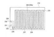
図8、図9、図10を用いて、燃焼器206,296と改質器208を一体化した反応装置210について説明する。図8は、反応装置210の斜視図であり、図9は、図8の面IXに沿った接合面における断面図であり、図10は、図8の面X−Xに沿った接合面における断面図である。なお、本発明に係る反応装置を反応装置210に適用している。 A
反応装置210は四枚の基板211〜214を備え、これら四枚の基板211〜214を積み重ねて接合したものが反応装置210の本体となる。ここで、第2燃焼器206の本体は、上基板211と中基板212とから構成され、改質器208の本体は、中基板212,213から構成され、第1燃焼器296は中基板213と下基板214とから構成され、中基板212が第2燃焼器206と改質器208に共通し、中基板213が第1燃焼器296と改質器208に共通している。 The
中基板212,213との接合部には、接合面に沿って葛折り状に設けられたマイクロ流路が設けられており、マイクロ流路の一端部が取込口217として中基板212,213の側面に形成され、マイクロ流路の他端部が排出口218として反対面に形成されている。マイクロ流路の壁面には、Cu/ZnO系触媒といった改質用触媒が形成されている。また、取込口217には管等を介して気化器207に接続され、気化器207で気化した燃料と水の混合気が取込口217からマイクロ流路に流入する。燃料と水の混合気はマイクロ流路を流動している時に上記化学反応式(1)、(2)のように反応する。排出口218には管等を介して一酸化炭素除去器209に接続され、生成物の混合気がマイクロ流路から排出口218を通じて一酸化炭素除去器209に供給される。 A micro flow channel provided in a twisted manner along the bonding surface is provided at a joint portion with the
図9に示すように、下基板214における中基板213との接合面側には、溝230aが形成されており、この溝230aは下基板214と中基板213との接合前にサンドブラスト法等を施すことによって形成されたものである。この溝230aを覆うようにして下基板214を中基板213に接合することによって、溝230aが接合面に沿った第1マイクロ流路230となる。第1マイクロ流路230は一様な幅、一様な深さを有し、その幅及び深さが2mm以下、望ましくは1.8mm以下が望ましい。この第1マイクロ流路230は、第1燃焼器296の流路である。 As shown in FIG. 9, a
第1マイクロ流路230は分岐しており、3つの端部を有する。第1マイクロ流路230の3つの端部のうち、第1端部、第2端部がそれぞれ取込口231,232として下基板214の側面に面しており、第3端部が排出口233として反対側の側面に面している。第1空気取込口231には管等を介して外部に通じており、空気(酸化剤として酸素を含む。)が第1空気取込口231から第1マイクロ流路230に流入する。燃料取込口232には管等を介して燃料容器202に通じており、燃料容器202から燃料が燃料取込口232から第1マイクロ流路230に流入する。排出口233には管等を介して外部に通じており、生成物が第1マイクロ流路230から排出口233を通じて外部に排出される。 The
第1マイクロ流路230の経路について説明する。合流部234においては、第1空気取込口231から合流部234までの経路235と、燃料取込口232から合流部234までの経路236と、合流部234から排出口233までの経路237とが合流している。なお、第1マイクロ流路230のうち、経路237が葛折り状に形成されている。 The route of the
合流部234から排出口233までの経路237のほぼ全域にわたってその壁面には、燃料用燃焼触媒238が形成されている。燃料用燃焼触媒238は、アルミナを担体として白金を担持させたものであり、燃料(メタノール)の酸化に適するよう白金の担持量が5wt%であるのが望ましい。 A
図10に示すように、上基板211の中基板212との接合面には、溝219aが形成されており、この溝219aは上基板211と中基板212との接合前にサンドブラスト法等を施すことによって形成されたものである。この溝219aを覆うようにして上基板211を中基板212に接合することによって、溝219aが接合面に沿った第2マイクロ流路219となる。第2マイクロ流路219は一様な幅、一様な深さを有し、その幅及び深さが2mm以下、望ましくは1.8mm以下が望ましい。この第2マイクロ流路219は、第2燃焼器206の流路である。 As shown in FIG. 10, a
第2マイクロ流路219は分岐しており、3つの端部を有する。第2マイクロ流路219の3つの端部のうち、第1端部、第2端部がそれぞれ取込口220,221として上基板211の側面に面しており、第3端部が排出口222として反対側の側面に面している。第2空気取込口220には管等を介して外部に通じており、空気(酸化剤として酸素を含む。)が第2空気取込口220から第2マイクロ流路219に流入する。水素取込口221には管等を介して燃料電池204の燃料極に通じており、燃料電池204の燃料極から水素等が水素取込口221から第2マイクロ流路219に流入する。排出口222には管等を介して外部に通じており、生成物が第2マイクロ流路219から排出口222を通じて外部に排出される。 The
第2マイクロ流路219の経路について説明する。合流部223においては、第2空気取込口220から合流部223までの経路224と、水素取込口221から合流部223までの経路225と、合流部223から排出口222までの経路226とが合流している。なお、第2マイクロ流路219のうち、経路226が葛折り状に形成されている。また、経路226は上基板211の中央部を通っている。 The route of the
合流部223から排出口222までの経路226のうちその中間部(図4において塗りつぶした領域)の壁面には、水素用燃焼触媒227が形成されている。水素用燃焼触媒227は、アルミナ(Al2O3)を担体として白金(Pt)を担持させたものであり、水素の酸化(燃焼)に適するよう白金の担持量が1wt%以下、好ましくは0.1〜0.5wt%が望ましい。A
気化器207と燃焼器206,296とからなる反応装置250に対しても、本発明に係る反応装置を適用している。反応装置250は、反応装置210とほぼ同様に構成されているので、反応装置250については反応装置210のいずれかの部分と同一の部分に対して同一の符号を付し、同一の部分についての説明は省略する。反応装置250の場合、気化器207の本体が中基板212,213から構成され、第2燃焼器206の本体が上基板211と中基板212から構成され、第1燃焼器296の本体が中基板213と下基板214から構成される。また、反応装置250の場合、気化器207のマイクロ流路の壁面には触媒が形成されていない。更に、反応装置250の場合、気化器207の取込口217が管を介して燃料容器202に接続され、気化器207の排出口233が改質器208の取込口217に接続さている。 The reaction apparatus according to the present invention is also applied to the
なお、反応装置210及び反応装置250は、ガラス等の断熱材からなる断熱パッケージ内に収容されている。 The
次に、反応装置210及び反応装置250の作用について説明する。
燃料電池204の燃料極から水素等が第2燃焼器205,206の水素取込口221に流入し、燃料容器202から燃料が第1燃焼器295,296の燃料取込口232に流入し、外部から空気が燃焼器205,206,295,296の取込口220,231に流入する。第2マイクロ流路219においては、水素等と空気が合流部223で混合され、その混合気が第2マイクロ流路219を流れている時に水素が水素用燃焼触媒227に接することによって水素が燃焼し、燃焼熱が発する。また、第1マイクロ流路230においては、燃料と空気が合流部234で混合し、燃料と空気の混合気が第1マイクロ流路230を流れている時に燃料が燃料用燃焼触媒238に接することによって、燃料が燃焼し、燃焼熱が発する。Next, the operation of the
Hydrogen or the like flows from the fuel electrode of the
燃料容器202から燃料と水が気化器207の取込口217に流入し、燃料と水が気化器207のマイクロ流路を流動している時に燃焼器205,295で発生した燃焼熱によって気化する。気化した燃料と水の混合気は気化器207の排出口218から排出され、改質器208の取込口217に流入する。燃料と水の混合気は、改質器208のマイクロ流路を流動している時に燃焼器206,296で発生した燃焼熱と改質用触媒の作用を受けて、水素に改質される(上記化学反応式(1)、(2)参照)。 Fuel and water flow from the
以上のように、水素用燃焼触媒227と燃料用燃焼触媒238が別々のマイクロ流路219,230に形成されている。そして、第1マイクロ流路230には水素が流れずに燃料と空気が流れるので、燃料が効率よく燃焼し、第2マイクロ流路219には燃料が流れずに水素等と空気が流れるので、水素が効率よく燃焼する。以上のように、水素と燃料を別々に燃焼させているので、水素と燃料の両方を簡単に完全燃焼させることができる。 As described above, the
また、酸化反応速度の早い水素を酸化させ水素用燃焼触媒227が上基板211の中央に形成されているから、熱効率が良くなる。 In addition, since the
したがって、燃料電池204の燃料極から燃焼器205、206に供給される水素の量がそれぞれ気化器207、改質器208での反応を引き起こすのに十分でなくても、燃焼器205、206には燃料容器202から燃焼するための燃料が供給されるので、気化器207、改質器208は反応を引き起こすのに十分な温度に設定することができ、また、燃料電池204の燃料極から燃焼器205、206に燃焼するための水素が供給されるので、燃料容器202からの燃料の消費量を抑えることができる。 Therefore, even if the amount of hydrogen supplied from the fuel electrode of the
なお上記各実施形態では、一酸化炭素除去器9には、気化器、改質器のように燃焼器が設けられていないが、同様な構造の燃焼器を設けてもよい。 In each of the above embodiments, the
また上記各実施形態では、燃料を燃焼する酸素源として空気取込口から空気を取り込んだが、これに限らず発電装置1内に蓄えられた過酸化マンガン等の酸化剤より生じた酸素をこれら取込口に取り込むようにしてもよい。このように外部の空気を取り込む箇所を制限することで燃焼器で燃焼される熱気が空気を熱媒体として外部に漏洩しないようにすることができる。 In each of the above embodiments, air is taken in from the air intake port as an oxygen source for burning the fuel. However, the present invention is not limited to this, and oxygen generated from an oxidant such as manganese peroxide stored in the power generator 1 is taken in. You may make it take in in a slot. In this way, by restricting the places where external air is taken in, the hot air combusted in the combustor can be prevented from leaking outside using air as a heat medium.
5,6 燃焼器
7 気化器(反応器)
8 改質器(反応器)
11 上基板(燃焼器本体の一部)
12 中基板(燃焼器本体の一部)
15 マイクロ流路(流路)
19,22 空気取込口
20 燃料取込口
21 水素取込口
25,27 燃料経路
29,31 水素経路
33 混合経路
34 水素用燃焼触媒
35 燃料用燃焼触媒
119 第1空気取込口
122 第2空気取込口
120 燃料取込口
121 水素取込口
131 第2マイクロ流路(第2流路)
133 第1マイクロ流路(第1流路)
134 水素用燃焼触媒
135 燃料用燃焼触媒
207 気化器(反応器)
208 改質器(反応器)
210,250 反応装置
211 上基板(第2燃焼器本体の一部)
212 中基板(第2燃焼器本体の一部)
213 中基板(第1燃焼器本体の一部)
214 下基板(第1燃焼器本体の一部)
219 第2マイクロ流路(第2流路)
220 第2空気取込口
221 水素取込口
227 水素用燃焼触媒
230 第1マイクロ流路(第1流路)
231 第1空気取込口
232 燃料取込口
238 燃料用燃焼触媒5,6
8 Reformer (Reactor)
11 Upper substrate (part of combustor body)
12 Medium substrate (part of combustor body)
15 Micro channel (channel)
19, 22
133 1st micro flow path (first flow path)
134 Combustion catalyst for
208 Reformer (Reactor)
210,250
212 Medium substrate (part of the second combustor body)
213 Medium substrate (part of the first combustor body)
214 Lower substrate (part of the first combustor body)
219 Second micro-channel (second channel)
220 2nd
231 First
Claims (5)
Translated fromJapanese前記流路の一部に形成された水素用燃焼触媒と、
前記流路の別の一部に形成された燃料用燃焼触媒と、
を備え、
前記流路は、燃料を取り込む燃料取込口から合流部までの燃料経路と、水素を取り込む水素取込口から前記合流部までの水素経路と、前記合流部から排出口までの混合経路とからなり、
前記水素用燃焼触媒を前記水素経路に形成し、前記燃料用燃焼触媒を前記混合経路と前記燃料経路とのうちの少なくとも一方に形成したことを特徴とする燃焼器。A combustor body having a flow path;
A hydrogen combustion catalyst formed in a part of the flow path;
A combustion catalyst for fuel formed in another part of the flow path;
With
The flow path includes a fuel path from a fuel intake port that takes in fuel to a merging portion, a hydrogen path from a hydrogen intake port that takes in hydrogen to the merging portion, and a mixing path from the merging portion to a discharge port. Become
The combustor, wherein the hydrogen combustion catalyst is formed in the hydrogen path, and the fuel combustion catalyst is formed in at least one of the mixing path and the fuel path.
Priority Applications (1)
| Application Number | Priority Date | Filing Date | Title |
|---|---|---|---|
| JP2004085037AJP4400273B2 (en) | 2004-03-23 | 2004-03-23 | Combustor and reactor |
Applications Claiming Priority (1)
| Application Number | Priority Date | Filing Date | Title |
|---|---|---|---|
| JP2004085037AJP4400273B2 (en) | 2004-03-23 | 2004-03-23 | Combustor and reactor |
Related Child Applications (2)
| Application Number | Title | Priority Date | Filing Date |
|---|---|---|---|
| JP2009129751ADivisionJP5182223B2 (en) | 2009-05-29 | 2009-05-29 | Reactor |
| JP2009129750ADivisionJP4983859B2 (en) | 2009-05-29 | 2009-05-29 | Combustor |
Publications (2)
| Publication Number | Publication Date |
|---|---|
| JP2005273954A JP2005273954A (en) | 2005-10-06 |
| JP4400273B2true JP4400273B2 (en) | 2010-01-20 |
Family
ID=35173827
Family Applications (1)
| Application Number | Title | Priority Date | Filing Date |
|---|---|---|---|
| JP2004085037AExpired - Fee RelatedJP4400273B2 (en) | 2004-03-23 | 2004-03-23 | Combustor and reactor |
Country Status (1)
| Country | Link |
|---|---|
| JP (1) | JP4400273B2 (en) |
Families Citing this family (2)
| Publication number | Priority date | Publication date | Assignee | Title |
|---|---|---|---|---|
| KR100764404B1 (en)* | 2005-12-29 | 2007-10-05 | 삼성전기주식회사 | Ceramic multilayer substrate reformer for micro fuel cell and manufacturing method thereof |
| JP2009295534A (en)* | 2008-06-09 | 2009-12-17 | Yamatake Corp | Fuel cell system and operation method for fuel cell system |
- 2004
- 2004-03-23JPJP2004085037Apatent/JP4400273B2/ennot_activeExpired - Fee Related
Also Published As
| Publication number | Publication date |
|---|---|
| JP2005273954A (en) | 2005-10-06 |
Similar Documents
| Publication | Publication Date | Title |
|---|---|---|
| EP1904220B1 (en) | Reactor | |
| JP2005314207A (en) | Reactor | |
| KR100627334B1 (en) | Reformer for fuel cell and fuel cell system comprising same | |
| KR100769393B1 (en) | Reactor | |
| JP2005103399A (en) | Reaction apparatus and reaction method | |
| US20040105789A1 (en) | Chemical reactor | |
| JP4983859B2 (en) | Combustor | |
| JP4983169B2 (en) | Reaction apparatus and electronic equipment | |
| JP4366483B2 (en) | Reactor | |
| JP4400273B2 (en) | Combustor and reactor | |
| JP5182223B2 (en) | Reactor | |
| JP4438569B2 (en) | Reactor | |
| JP5103754B2 (en) | Fuel cell device | |
| JP4665803B2 (en) | Reactor | |
| US20080113234A1 (en) | Reaction device and electronic device | |
| JP5168750B2 (en) | Vaporizer, reactor and power generator | |
| JP4254769B2 (en) | Reactor | |
| JP5168751B2 (en) | Vaporizer, reactor and power generator | |
| JP5228739B2 (en) | Reaction apparatus and electronic equipment | |
| JP4715405B2 (en) | Reactor | |
| JP4371091B2 (en) | Reactor | |
| JP5229269B2 (en) | Reactor | |
| JP4586700B2 (en) | Reactor | |
| JP2008066073A (en) | Power generation system and electronic device equipped with the power generation system | |
| JP2005238100A (en) | Reactor and channel structure |
Legal Events
| Date | Code | Title | Description |
|---|---|---|---|
| A621 | Written request for application examination | Free format text:JAPANESE INTERMEDIATE CODE: A621 Effective date:20070320 | |
| A977 | Report on retrieval | Free format text:JAPANESE INTERMEDIATE CODE: A971007 Effective date:20090319 | |
| A131 | Notification of reasons for refusal | Free format text:JAPANESE INTERMEDIATE CODE: A131 Effective date:20090331 | |
| A521 | Written amendment | Free format text:JAPANESE INTERMEDIATE CODE: A523 Effective date:20090529 | |
| A131 | Notification of reasons for refusal | Free format text:JAPANESE INTERMEDIATE CODE: A131 Effective date:20090714 | |
| A521 | Written amendment | Free format text:JAPANESE INTERMEDIATE CODE: A523 Effective date:20090831 | |
| TRDD | Decision of grant or rejection written | ||
| A01 | Written decision to grant a patent or to grant a registration (utility model) | Free format text:JAPANESE INTERMEDIATE CODE: A01 Effective date:20091006 | |
| A01 | Written decision to grant a patent or to grant a registration (utility model) | Free format text:JAPANESE INTERMEDIATE CODE: A01 | |
| R150 | Certificate of patent or registration of utility model | Free format text:JAPANESE INTERMEDIATE CODE: R150 | |
| A61 | First payment of annual fees (during grant procedure) | Free format text:JAPANESE INTERMEDIATE CODE: A61 Effective date:20091019 | |
| FPAY | Renewal fee payment (event date is renewal date of database) | Free format text:PAYMENT UNTIL: 20121106 Year of fee payment:3 | |
| FPAY | Renewal fee payment (event date is renewal date of database) | Free format text:PAYMENT UNTIL: 20131106 Year of fee payment:4 | |
| LAPS | Cancellation because of no payment of annual fees |