JP4399191B2 - Helicopter - Google Patents
HelicopterDownload PDFInfo
- Publication number
- JP4399191B2 JP4399191B2JP2003146403AJP2003146403AJP4399191B2JP 4399191 B2JP4399191 B2JP 4399191B2JP 2003146403 AJP2003146403 AJP 2003146403AJP 2003146403 AJP2003146403 AJP 2003146403AJP 4399191 B2JP4399191 B2JP 4399191B2
- Authority
- JP
- Japan
- Prior art keywords
- fuselage
- helicopter
- downwash
- medicine
- spraying
- Prior art date
- Legal status (The legal status is an assumption and is not a legal conclusion. Google has not performed a legal analysis and makes no representation as to the accuracy of the status listed.)
- Expired - Fee Related
Links
- 238000005507sprayingMethods0.000claimsdescription24
- 239000003337fertilizerSubstances0.000claimsdescription6
- 239000000126substanceSubstances0.000claimsdescription4
- 239000003814drugSubstances0.000description39
- 230000001788irregularEffects0.000description13
- 229940079593drugDrugs0.000description12
- 230000000694effectsEffects0.000description8
- 238000000034methodMethods0.000description3
- 239000007921spraySubstances0.000description3
- 238000003912environmental pollutionMethods0.000description2
- 238000004519manufacturing processMethods0.000description2
- 239000003795chemical substances by applicationSubstances0.000description1
- 239000002131composite materialSubstances0.000description1
- 125000004122cyclic groupChemical group0.000description1
- 230000007423decreaseEffects0.000description1
- 230000003111delayed effectEffects0.000description1
- 230000001771impaired effectEffects0.000description1
- 239000000463materialSubstances0.000description1
- 229910052751metalInorganic materials0.000description1
- 239000002184metalSubstances0.000description1
- 150000002739metalsChemical class0.000description1
- 238000007493shaping processMethods0.000description1
- 230000006641stabilisationEffects0.000description1
- 238000011105stabilizationMethods0.000description1
- 229920003002synthetic resinPolymers0.000description1
- 239000000057synthetic resinSubstances0.000description1
- XLYOFNOQVPJJNP-UHFFFAOYSA-NwaterSubstancesOXLYOFNOQVPJJNP-UHFFFAOYSA-N0.000description1
- 239000002023woodSubstances0.000description1
Images


Classifications
- B—PERFORMING OPERATIONS; TRANSPORTING
- B64—AIRCRAFT; AVIATION; COSMONAUTICS
- B64D—EQUIPMENT FOR FITTING IN OR TO AIRCRAFT; FLIGHT SUITS; PARACHUTES; ARRANGEMENT OR MOUNTING OF POWER PLANTS OR PROPULSION TRANSMISSIONS IN AIRCRAFT
- B64D1/00—Dropping, ejecting, releasing or receiving articles, liquids, or the like, in flight
- B64D1/16—Dropping or releasing powdered, liquid, or gaseous matter, e.g. for fire-fighting
- B64D1/18—Dropping or releasing powdered, liquid, or gaseous matter, e.g. for fire-fighting by spraying, e.g. insecticides
- B—PERFORMING OPERATIONS; TRANSPORTING
- B64—AIRCRAFT; AVIATION; COSMONAUTICS
- B64C—AEROPLANES; HELICOPTERS
- B64C23/00—Influencing air flow over aircraft surfaces, not otherwise provided for
- B—PERFORMING OPERATIONS; TRANSPORTING
- B64—AIRCRAFT; AVIATION; COSMONAUTICS
- B64C—AEROPLANES; HELICOPTERS
- B64C5/00—Stabilising surfaces
- B64C5/10—Stabilising surfaces adjustable
- B64C5/12—Stabilising surfaces adjustable for retraction against or within fuselage or nacelle
- B—PERFORMING OPERATIONS; TRANSPORTING
- B64—AIRCRAFT; AVIATION; COSMONAUTICS
- B64C—AEROPLANES; HELICOPTERS
- B64C27/00—Rotorcraft; Rotors peculiar thereto
- B64C27/04—Helicopters
Landscapes
- Engineering & Computer Science (AREA)
- Aviation & Aerospace Engineering (AREA)
- Life Sciences & Earth Sciences (AREA)
- Pest Control & Pesticides (AREA)
- Catching Or Destruction (AREA)
- Toys (AREA)
Description
Translated fromJapanese【0001】
【発明の属する技術分野】
本発明は、ヘリコプタに関し、特に、ダウンウォッシュの整流機能を有するヘリコプタに関する。
【0002】
【従来の技術】
従来より、農業分野等において、ヘリコプタを使用した薬剤や肥料の散布が実施されている。かかる散布の際には、ヘリコプタをほぼホバリングに近い低速でかつ地面効果の影響が高い高度で飛行させることにより、ヘリコプタのロータの回転により発生したダウンウォッシュを効果的に利用して、散布対象である作物の葉の裏側まで薬剤を霧状にして付着させている。
【0003】
ヘリコプタのロータの回転により発生したダウンウォッシュの流れを、図6に示した。図6に示すように、ダウンウォッシュDはヘリコプタ100の胴体側面110に沿って高速で下方に流れ、胴体下面120で剥離して不規則な空気流Cとなることが知られている。従って、胴体下面120に散布用のノズルを配置すると、不規則な空気流Cによって胴体下面120に薬剤が大量に付着し、付着した薬剤が水滴状になって落下したり一部の薬剤が散布されなかったりして、散布効率が低下する。このため、図7に示すようにノズル200をヘリコプタ100の胴体101から離隔させて配置する場合が多い。
【0004】
近年においては、かかるダウンウォッシュの流れを制御するための技術も種々提案されている。例えば、ヘリコプタの胴体上部に整流手段(整形部材、偏流板、カバー等)を設けることにより、胴体下方に位置する救助者や作業者が強いダウンウォッシュに直接的に曝されるのを回避する技術が提案されている(例えば、特許文献1参照。)。
【0005】
【特許文献1】
特開平7−47998号公報(第1頁、第1図)
【0006】
【発明が解決しようとする課題】
ところで、ヘリコプタによる薬剤の散布の際には、ヘリコプタのロータの回転により発生したダウンウォッシュにより薬剤を拡散させる方が効果的であるが、前記した特許文献1に記載の技術を採用すると、ダウンウォッシュを有効に利用することができないという問題がある。
【0007】
また、ノズルをヘリコプタの胴体から離隔させて配置する方式(図7参照)を採用すると、ダウンウォッシュによって胴体下方に薬剤を付着させないためには、ノズルを装着する支持部材を長くする必要があるため、ヘリコプタの重量が増加してしまう。このため、ヘリコプタの軽量化を図りながら散布効率を向上させるための新たな工夫が待望されていた。
【0008】
また、薬剤等の散布時においては、前記したようにヘリコプタをほぼホバリングに近い低速でかつ地面効果の影響が高い高度で飛行させるため、ダウンウォッシュによって胴体下方に不規則な空気流が発生すると、飛行中の機体の安定性が損なわれ、操縦性も低下してしまうという問題があった。
【0009】
本発明の課題は、薬剤等の散布に使用されるヘリコプタにおいて、ダウンウォッシュの有効利用を図りながら胴体下面に薬剤等が付着するのを阻止して散布効率を向上させるとともに、ホバリングに近い低速でかつ地面効果の影響が高い高度で飛行させる散布飛行等において、飛行中の機体の安定性及び操縦性を向上させることである。
【0010】
【課題を解決するための手段】
以上の課題を解決するため、請求項1に記載の発明は、ヘリコプタであって、薬剤や肥料を散布するためのノズルを胴体下面のみに備え、胴体側面下部ないし胴体下面側方部に、下方に向けて設けられた整流手段を備えることを特徴とする。
【0011】
請求項1に記載の発明によれば、胴体側面下部ないし胴体下面側方部に下方に向けて設けられた整流手段により、胴体側面に沿って流れるダウンウォッシュを整った流れのまま胴体から離隔させるように導くことができる。従って、胴体の有無にかかわらずダウンウォッシュは地表面まで整った流れとなるので、ヘリコプタを用いて薬剤散布等を実施した場合に、薬剤等を効果的に拡散させることができる。
【0012】
また、請求項1に記載の発明によれば、胴体側面下部ないし胴体下面側方部に下方に向けて設けられた整流手段により、ダウンウォッシュが胴体下方に流入するのを阻止することができる。このため、胴体下方における不規則な空気流の発生を抑制することができる。従って、ヘリコプタを用いて薬剤散布等を実施した場合に、胴体下面に薬剤が付着するのを防ぐことができるので、散布効率を向上させることができるとともに、胴体下面に付着した薬剤等の除去作業が不要となる。
【0013】
また、請求項1に記載の発明によれば、胴体側面下部ないし胴体下面側方部に下方に向けて設けられた整流手段により、胴体下方における不規則な空気流の発生を抑制することができるので、ホバリングに近い低速でかつ地面効果の影響が高い高度で飛行させる散布飛行等において、飛行中の機体の姿勢を安定させることができ、さらに、機体の操縦性を格段に向上させることができる。
【0014】
請求項2に記載の発明は、ヘリコプタであって、薬剤や肥料を散布するためのノズルを胴体下面のみに備え、胴体側面下部ないし胴体下面側方部に、胴体側面に沿って流れるダウンウォッシュを胴体から離隔させるように導く整流手段が設けられていることを特徴とする。
【0015】
請求項2に記載の発明によれば、胴体側面下部ないし胴体下面側方部に設けられた整流手段により、胴体側面に沿って流れるダウンウォッシュを胴体から離隔させるように導くことができる。従って、ダウンウォッシュにより胴体側方に循環流を発生させることができるので、ヘリコプタを用いて薬剤散布等を実施した場合に、薬剤等を効果的に拡散させることができる。
【0016】
また、請求項2に記載の発明によれば、胴体側面に沿って流れるダウンウォッシュを胴体から離隔させるように導く整流手段が、胴体側面下部ないし胴体下面側方部に設けられているので、ダウンウォッシュが胴体下方に流入するのを阻止することができる。このため、胴体下方における不規則な空気流の発生を抑制することができる。従って、ヘリコプタを用いて薬剤散布等を実施した場合に、胴体下面に薬剤が付着するのを防ぐことができるので、散布効率を向上させることができるとともに、胴体下面に付着した薬剤等の除去作業が不要となる。
【0017】
また、請求項2に記載の発明によれば、胴体側面下部ないし胴体下面側方部に設けられた整流手段により、胴体下方における不規則な空気流の発生を抑制することができるので、ホバリングに近い低速でかつ地面効果の影響が高い高度で飛行させる散布飛行等において、飛行中の機体の姿勢を安定させることができ、さらに、機体の操縦性を格段に向上させることができる。
【0021】
請求項3に記載の発明は、請求項1又は請求項2に記載のヘリコプタにおいて、胴体上方のダウンウォッシュを胴体下方へと導く流路が、胴体内部に設けられていることを特徴とする。
【0022】
請求項3に記載の発明によれば、胴体内部に、胴体上方のダウンウォッシュを胴体下方へと導く流路が設けられているので、胴体下方の空間に空気を補充して、胴体下方の圧力を常時正圧に保つことができる。従って、胴体側面に沿って流れたダウンウォッシュが胴体下方に流入するのを確実に阻止することができる。この結果、胴体下方における不規則な空気流の発生を効果的に抑制することができる。
【0023】
【発明の実施の形態】
以下、本発明の実施の形態を、図を用いて詳細に説明する。
【0024】
[第1の実施の形態]
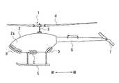
まず、第1の実施の形態に係るヘリコプタ1の構成について、図1〜図3を用いて説明する。ヘリコプタ1は、胴体2、胴体2の上部に回転軸3を介して取り付けられたメインロータ4、胴体2の下部に取り付けられたスキッド5、胴体2の後方に結合されたテールブーム6、テールブーム6の後方先端に取り付けられたテールロータ7、胴体2の両側面2aの下部に取り付けられた整流板8、等を備えて構成されている(図1及び図2参照)。なお、ヘリコプタ1は薬剤や肥料の散布に使用されるものであり、胴体2の下面2bに(図示されていない)散布用のノズルを備えている。
【0025】
胴体2の内部には、操縦席や荷物室が設けられるとともに、メインロータ4やテールロータ7を駆動するためのエンジンや、サイクリックスティック・コレクティブスティック・ペダル等の操縦装置が搭載されている。エンジンを駆動してメインロータ4を回転させると、図1に示すようなダウンウォッシュDが発生する。
【0026】
整流板8は、本発明における整流手段の一例であり、胴体2の両側面2aの下部に、斜め下方向(図1の右下方向及び左下方向)に向けて突出するように取り付けられている。すなわち、ヘリコプタ1を正面から見た場合に、整流板8は「ハ字状」の外観を呈している(図1参照)。整流板8は、胴体2の両側面2aに沿って流れるダウンウォッシュDを、胴体2から離隔させるように図1の右下方向・左下方向に導いて、ダウンウォッシュDが胴体2の下方空間Uに流入するのを阻止するものである。
【0027】
整流板8は、胴体2の両側面2aの下部に前後にわたって設けられる。胴体2の両側面2aの下部における前部から後部までの略全範囲Aに整流板8を設けてもよく(図2参照)、胴体2の両側面2aの下部における前部B、中央部C及び後部Dに整流板8を分割して設けてもよい(図3参照)。また、整流板8は、各種金属、各種合成樹脂、各種ゴム材料、木材又はこれらの複合材等で構成することができる。
【0028】
整流板8の高さ(胴体2の両側面2aからの法線方向の寸法)は、胴体2の両側面2aの境界層厚さより大きい値に設定しておく。ダウンウォッシュDは、胴体2の両側面2aに沿って流れるが、胴体2の両側面2aから一定距離(境界層厚さ)だけ離隔した領域においては粘性の影響を受けないため、その流速は高い。一方、胴体2の両側面2aの近傍(境界層内)においては、ダウンウォッシュDは粘性の影響を受けて流速が低くなる。従って、整流板8によってダウンウォッシュDを制御するためには、整流板8の高さを胴体2の両側面2aの境界層厚さより大きい値に設定する必要がある。本実施の形態においては、整流板8の高さを約40mmに設定している。
【0029】
本実施の形態に係るヘリコプタ1においては、胴体2の両側面2aの下部に設けられた整流板8により、ダウンウォッシュDを胴体2から離隔させるように図1の右下方向・左下方向に導いて、胴体2の両側面2aに沿って流れるダウンウォッシュDを整った流れのまま胴体2から離隔させるように導くことができる。従って、ダウンウォッシュDは胴体2の有無にかかわらず地表面まで整った流れとなるので、散布対象である作物の葉の裏側まで薬剤を付着させることができる。
【0030】
また、本実施の形態に係るヘリコプタ1においては、胴体2の両側面2aの下部に、ダウンウォッシュDを胴体2から離隔させるように導く整流板8が設けられているので、ダウンウォッシュDが胴体2の下方空間U(図1参照)に流入するのを阻止することができる。従って、胴体2の下方空間Uにおいて不規則な空気流が発生するのを抑制することができるので、胴体2の下面2bに薬剤が付着するのを防ぐことができる。このため、散布効率を向上させることができるとともに、胴体2の下面2bに付着した薬剤の除去作業が不要となる。
【0031】
また、胴体2の下面2bに薬剤が付着すると薬剤が濃縮されて高濃度となり、この高濃度の薬剤を散布地以外の場所で除去すると環境汚染をもたらす場合があるが、本実施の形態に係るヘリコプタ1には整流板8が設けられているので、胴体2の下面2bに薬剤が付着するのを防ぐことができる。従って、薬剤除去に起因する環境汚染を防ぐことができる。
【0032】
また、散布用のノズルをヘリコプタ1の胴体2から離隔させて配置する方式(図7参照)を採用すると、ノズルの支持部材を長くする必要があるために機体重量が増加してしまう上に、ノズルへの薬剤の供給が滞って散布効率が低下する場合があるが、本実施の形態に係るヘリコプタ1には整流板8が設けられており、胴体2の下面2bに薬剤が付着するのを防ぐことができるので、胴体2の下面2bにノズルを配置することができる。従って、機体の軽量化を達成することができるとともに、薬剤等の安定的な供給を実現させて散布効率を向上させることができる。
【0033】
また、本実施の形態に係るヘリコプタ1においては、胴体2の両側面2aの下部に設けられた整流板8により、胴体2の下方空間Uにおける不規則な空気流の発生を抑制することができるので、ホバリングに近い低速でかつ地面効果の影響が高い高度で飛行させる散布飛行等において、飛行中の機体の姿勢を安定させることができ、さらに、機体の操縦性を格段に向上させることができる。
【0034】
[第2の実施の形態]
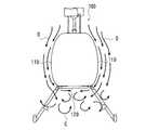
次に、第2の実施の形態に係るヘリコプタ10の構成について、図4及び図5を用いて説明する。なお、本実施の形態に係るヘリコプタ10は、第1の実施の形態に係るヘリコプタ1の胴体2内部に特定の流路(胴体2上方のダウンウォッシュDを胴体2の下方空間Uへと導く流路)を設けたものである。従って、ヘリコプタ1と同一の構成については同一の符号を付すこととする。
【0035】
本実施の形態に係るヘリコプタ10の胴体2の前部には上方開口部9a及び下方開口部9bが設けられており、胴体2の内部前方には中空部9cが設けられている(図4及び図5参照)。これら上方開口部9a、中空部9c及び下方開口部9bによって、本発明における流路が形成されることとなる。ヘリコプタ10のメインロータ4の回転によって発生したダウンウォッシュDは、胴体2の上方開口部9aから中空部9cに流入する。そして、下方開口部9bから下方空間Uへと流出する。
【0036】
また、ヘリコプタ10の胴体2の後部には上方開口部9d及び下方開口部9eが設けられており、胴体2の内部後方には中空部9fが設けられている(図5参照)。これら上方開口部9d、中空部9f及び下方開口部9eによって、本発明における流路が形成されることとなる。ヘリコプタ10のメインロータ4の回転によって発生したダウンウォッシュDは、胴体2の上方開口部9dから中空部9fに流入する。そして、下方開口部9eから下方空間Uへと流出する。
【0037】
本実施の形態に係るヘリコプタ10においては、胴体2の上方開口部9a、9dと、胴体2内部の中空部9c、9fと、胴体2の下方開口部9b、9eと、から形成される胴体2内部の流路により、胴体2上方のダウンウォッシュDを胴体2の下方空間Uへ導くことができる(図4及び図5参照)。従って、胴体2の下方空間Uに空気を補充して、この下方空間Uの圧力を常時正圧に保つことができる。この結果、胴体2の両側面2a及び整流板8に沿って流れたダウンウォッシュDが胴体2の下方空間Uに流入するのを確実に阻止することができるので、この下方空間Uにおける不規則な空気流の発生を効果的に抑制することができる。
【0038】
なお、以上の実施の形態においては、整流板8を正面から見た場合に「ハ字状」になるように(図1及び図4の右下方向・左下方向に延在するように)取り付けたが、胴体2の両側面2aに対する整流板8の取付角度は適宜変更可能である。また、整流板8を胴体2の両側面2aに張出・格納自在に設けておき、薬剤散布時には整流板8を両側面2aから外方に張り出させる一方、通常飛行時には整流板8を胴体2内に格納するようにしてもよい。
【0039】
また、以上の実施の形態においては、胴体2の両側面2aに左右対称に整流板8を設けた例を示した(図1及び図4参照)が、必ずしも整流板8を左右対称に設けなくてもよい。特に、メインロータ4の回転方向によってダウンウォッシュDの流れの方向が胴体2の左右で著しく異なる場合には、そのダウンウォッシュDの流れの方向に合わせて整流板8を設けるのが好ましい。
【0040】
また、以上の実施の形態においては、胴体2の両側面2aの下部に整流板8を設けた例を示した(図1及び図4参照)が、胴体2の下面2bの側方部(両側面2aの近傍部分)に斜め下方向(図1及び図4の右下方向及び左下方向)に向けて整流板8を取り付けてもよい。このように胴体2の下面2bの側方部に整流板8を設けた場合においても、胴体2の両側面2aに沿って流れるダウンウォッシュDを胴体2から離隔させるように導くことができる。
【0041】
また、以上の実施の形態においては、整流手段として整流板8を採用したが、このような板状の部材に限らず、ブロック状の部材を整流手段として採用することもできる。すなわち、胴体2の両側面2aに沿って流れるダウンウォッシュDを胴体2から離隔させるように導く機能を果たす構成であれば、いかなる構成をも整流手段として採用することができる。
【0042】
また、第2の実施の形態においては、胴体2の上部・下部に開口部を設けてこれらを中空部で連通することにより、胴体2内部に流路を形成したが、この流路に沿って壁等を設ける必要はない。また、流路形状(上部開口部9a、9dや下部開口部9b、9eの面積・形状、中空部9c、9fの容積・形状)は、ダウンウォッシュDの流速等によって適宜決めることができる。
【0043】
【発明の効果】
請求項1又は2に記載の発明によれば、胴体側面下部ないし胴体下面側方部に設けられた整流手段により、胴体側面に沿って流れるダウンウォッシュを胴体から離隔させるように導くことができるので、ヘリコプタを用いて薬剤等の散布を実施する場合に、ダウンウォッシュを有効利用することができる。
【0044】
また、請求項1又は請求項2に記載の発明によれば、整流部材により、ダウンウォッシュが胴体下方に流入するのを阻止できるので、胴体下方における不規則な空気流の発生を抑制できる。従って、ヘリコプタを用いて薬剤等の散布を実施した場合に、胴体下面に薬剤等が付着するのを防止でき、散布効率の向上及び薬剤除去作業の削減を実現できるとともに、散布飛行中における機体の姿勢の安定化及び機体の操縦性の向上を実現できる。
【0045】
請求項3に記載の発明によれば、胴体内部に、胴体上方のダウンウォッシュを胴体下方へと導く流路が設けられるので、胴体側面に沿って流れるダウンウォッシュが胴体下方に流入するのを確実に阻止することができる。この結果、胴体下方における不規則な空気流の発生を効果的に抑制することができる。
【図面の簡単な説明】
【図1】 本発明の第1の実施の形態に係るヘリコプタの正面図である。
【図2】 図1に示したヘリコプタ(整流板を胴体側面の下部の略全範囲に設けた場合)の側面図である。
【図3】 図1に示したヘリコプタ(整流板を胴体側面の下部に分割して設けた場合)の側面図である。
【図4】 本発明の第2の実施の形態に係るヘリコプタの正面図である。
【図5】 図4に示したヘリコプタの側断面図である。
【図6】 従来のヘリコプタの正面図である。
【図7】 図6に示したヘリコプタに薬剤散布用のノズルを取り付けた状態を示す正面図である。
【符号の説明】
1、10 ヘリコプタ
2 胴体
2a 側面
2b 下面
8 整流板(整流手段)
9a、9d 上方開口部(流路)
9b、9e 下方開口部(流路)
9c、9f 中空部(流路)
D ダウンウォッシュ[0001]
BACKGROUND OF THE INVENTION
The present invention relates to a helicopter, and more particularly to a helicopter having a downwash rectification function.
[0002]
[Prior art]
Conventionally, in the field of agriculture and the like, spraying of drugs and fertilizers using helicopters has been carried out. During such spraying, the helicopter is operated at a low speed almost close to hovering and at an altitude that is highly affected by the ground effect, so that the downwash generated by the rotation of the helicopter rotor can be effectively used to A chemical is sprayed and attached to the backside of a crop.
[0003]
The flow of downwash generated by the rotation of the helicopter rotor is shown in FIG. As shown in FIG. 6, it is known that the downwash D flows downward at a high speed along the
[0004]
In recent years, various techniques for controlling the flow of downwash have been proposed. For example, by providing rectifying means (shaping members, drift plates, covers, etc.) on the upper part of the helicopter fuselage, it is possible to prevent the rescuer or worker located below the fuselage from being directly exposed to strong downwash. Has been proposed (see, for example, Patent Document 1).
[0005]
[Patent Document 1]
Japanese Unexamined Patent Publication No. 7-47998 (first page, FIG. 1)
[0006]
[Problems to be solved by the invention]
By the way, when spraying a medicine by a helicopter, it is more effective to diffuse the medicine by downwash generated by the rotation of the rotor of the helicopter. However, when the technique described in
[0007]
In addition, if a system (see FIG. 7) in which the nozzle is arranged separately from the helicopter fuselage is employed, it is necessary to lengthen the support member on which the nozzle is mounted in order to prevent the drug from adhering below the fuselage by downwashing. The weight of the helicopter will increase. For this reason, a new device for improving the spraying efficiency while reducing the weight of the helicopter has been awaited.
[0008]
In addition, when spraying drugs, etc., as described above, because the helicopter flies at a low altitude that is almost close to hovering and has a high effect of the ground effect, when an irregular air flow occurs below the fuselage due to downwash, There was a problem that the stability of the aircraft during the flight was impaired, and the maneuverability also deteriorated.
[0009]
An object of the present invention is to improve the spraying efficiency by preventing the adhesion of medicines and the like to the lower surface of the fuselage while effectively using downwash in a helicopter used for spraying medicines, and at a low speed close to hovering. In addition, it is to improve the stability and maneuverability of the aircraft during flight, such as in scattered flight where the aircraft is flying at an altitude where the influence of the ground effect is high.
[0010]
[Means for Solving the Problems]
In order to solve the above-described problems, the invention described in
[0011]
According to the first aspect of the present invention, the downwash flowing along the fuselage side face is separated from the fuselage while maintaining a steady flow by the rectifying means provided downward on the fuselage side lower part or the fuselage lower surface side part. Can be guided as follows. Accordingly, since the downwash flows to the ground surface regardless of the presence or absence of the torso, the medicine and the like can be effectively diffused when the medicine is sprayed using a helicopter.
[0012]
Further, according to the first aspect of the present invention, it is possible to prevent the downwash from flowing into the lower part of the fuselage by the rectifying means provided downward at the lower part of the fuselage side surface or the lateral part of the lower face of the fuselage. For this reason, generation | occurrence | production of the irregular airflow in the trunk | drum lower part can be suppressed. Therefore, when a medicine is sprayed using a helicopter, it is possible to prevent the medicine from adhering to the lower surface of the fuselage, so that it is possible to improve the spraying efficiency and to remove the medicine adhering to the lower surface of the fuselage. Is no longer necessary.
[0013]
In addition, according to the first aspect of the present invention, it is possible to suppress the generation of an irregular air flow in the lower part of the fuselage by the rectifying means provided downward in the lower part of the fuselage side surface or in the lateral part of the lower part of the fuselage. Therefore, it is possible to stabilize the attitude of the aircraft during flight, such as in scattered flight where it is flying at a low speed close to hovering and with a high ground effect, and the maneuverability of the aircraft can be greatly improved. .
[0014]
The invention according to
[0015]
According to the second aspect of the present invention, the downwash flowing along the fuselage side face can be guided away from the fuselage by the rectifying means provided at the lower part of the fuselage side face or the side part of the lower face of the fuselage. Therefore, since a circulation flow can be generated on the side of the body by downwashing, when a medicine is sprayed using a helicopter, the medicine and the like can be effectively diffused.
[0016]
According to the second aspect of the present invention, the rectifying means for guiding the downwash flowing along the side surface of the fuselage to be separated from the fuselage is provided at the lower part of the fuselage side or the side of the lower side of the fuselage. It is possible to prevent the wash from flowing below the fuselage. For this reason, generation | occurrence | production of the irregular airflow in the trunk | drum lower part can be suppressed. Therefore, when a medicine is sprayed using a helicopter, it is possible to prevent the medicine from adhering to the lower surface of the fuselage, so that it is possible to improve the spraying efficiency and to remove the medicine adhering to the lower surface of the fuselage. Is no longer necessary.
[0017]
Further, according to the invention described in
[0021]
According to athird aspect of the present invention, in the helicopter according to the firstor second aspect , a flow path for guiding the downwash above the fuselage to the fuselage downward is provided inside the fuselage.
[0022]
According to thethird aspect of the present invention, since the flow path for guiding the downwash above the fuselage to the fuselage downward is provided inside the fuselage, the space below the fuselage is replenished with air to reduce the pressure below the fuselage. Can always be maintained at a positive pressure. Accordingly, it is possible to reliably prevent the downwash flowing along the side surface of the body from flowing into the lower side of the body. As a result, it is possible to effectively suppress the generation of an irregular air flow below the fuselage.
[0023]
DETAILED DESCRIPTION OF THE INVENTION
Hereinafter, embodiments of the present invention will be described in detail with reference to the drawings.
[0024]
[First embodiment]
First, the configuration of the
[0025]
Inside the
[0026]
Rectifying
[0027]
The rectifying
[0028]
The height of the current plate 8 (the dimension in the normal direction from the both
[0029]
In the
[0030]
Further, in the
[0031]
Further, when the drug adheres to the
[0032]
In addition, when adopting a method (see FIG. 7) in which the nozzles for spraying are arranged separately from the
[0033]
Further, in the
[0034]
[Second Embodiment]
Next, the configuration of the
[0035]
An
[0036]
Further, an
[0037]
In
[0038]
In the above embodiment, the
[0039]
Moreover, in the above embodiment, although the example which provided the
[0040]
Moreover, in the above embodiment, the example which provided the
[0041]
Further, in the above embodiments, but bythe rectifying handstage employs a rectifying
[0042]
In the second embodiment, the flow path is formed inside the
[0043]
【The invention's effect】
According to the first or second aspect of the present invention, the downwash flowing along the fuselage side surface can be guided away from the fuselage by the rectifying means provided at the lower part of the fuselage side surface or the side part of the fuselage lower surface. The downwash can be used effectively when the helicopter is used to spray the medicine or the like.
[0044]
Further, according to the invention described in
[0045]
According to the invention described in
[Brief description of the drawings]
FIG. 1 is a front view of a helicopter according to a first embodiment of the present invention.
2 is a side view of the helicopter shown in FIG. 1 (in the case where a rectifying plate is provided in substantially the entire lower portion of the side surface of the fuselage).
3 is a side view of the helicopter shown in FIG. 1 (when the current plate is divided and provided at the lower part of the fuselage side surface). FIG.
FIG. 4 is a front view of a helicopter according to a second embodiment of the present invention.
5 is a side sectional view of the helicopter shown in FIG. 4. FIG.
FIG. 6 is a front view of a conventional helicopter.
7 is a front view showing a state where a nozzle for spraying medicine is attached to the helicopter shown in FIG. 6. FIG.
[Explanation of symbols]
1,10
9a, 9d Upper opening (flow path)
9b, 9e Lower opening (flow path)
9c, 9f Hollow part (flow path)
D down wash
Claims (3)
Translated fromJapanesePriority Applications (4)
| Application Number | Priority Date | Filing Date | Title |
|---|---|---|---|
| JP2003146403AJP4399191B2 (en) | 2003-05-23 | 2003-05-23 | Helicopter |
| EP04252900AEP1479605B1 (en) | 2003-05-23 | 2004-05-19 | Helicopter |
| DE602004027577TDE602004027577D1 (en) | 2003-05-23 | 2004-05-19 | helicopter |
| US10/849,132US7278606B2 (en) | 2003-05-23 | 2004-05-20 | Helicopter having a fusilage section and a tail section coupled thereto |
Applications Claiming Priority (1)
| Application Number | Priority Date | Filing Date | Title |
|---|---|---|---|
| JP2003146403AJP4399191B2 (en) | 2003-05-23 | 2003-05-23 | Helicopter |
Publications (2)
| Publication Number | Publication Date |
|---|---|
| JP2004345553A JP2004345553A (en) | 2004-12-09 |
| JP4399191B2true JP4399191B2 (en) | 2010-01-13 |
Family
ID=33095490
Family Applications (1)
| Application Number | Title | Priority Date | Filing Date |
|---|---|---|---|
| JP2003146403AExpired - Fee RelatedJP4399191B2 (en) | 2003-05-23 | 2003-05-23 | Helicopter |
Country Status (4)
| Country | Link |
|---|---|
| US (1) | US7278606B2 (en) |
| EP (1) | EP1479605B1 (en) |
| JP (1) | JP4399191B2 (en) |
| DE (1) | DE602004027577D1 (en) |
Families Citing this family (8)
| Publication number | Priority date | Publication date | Assignee | Title |
|---|---|---|---|---|
| US7686245B2 (en)* | 2006-09-01 | 2010-03-30 | The Boeing Company | Rotary aircraft download alleviation apparatus and methods |
| JP2009196486A (en) | 2008-02-21 | 2009-09-03 | Yamaha Motor Co Ltd | Unmanned helicopter |
| CN104627368A (en)* | 2013-11-14 | 2015-05-20 | 现代农装科技股份有限公司 | Ground effect flying pesticide sprayer |
| CN104494816B (en)* | 2014-12-05 | 2016-04-13 | 宁波达鹏无人机科技有限公司 | Be exclusively used in the unmanned plane spraying field stalk herbicide |
| DE102017008721A1 (en) | 2017-09-16 | 2019-03-21 | protectismundi GmbH | Method and device for skyscraper firefighting |
| CN107719676B (en)* | 2017-11-29 | 2018-12-14 | 山东龙翼航空科技有限公司 | It is a kind of to spray the intelligent agricultural plant protection unmanned plane precisely and having a smooth flight |
| KR102498480B1 (en)* | 2018-01-15 | 2023-02-10 | 가부시키가이샤 드론 네트 | remote control spray device |
| WO2020110400A1 (en)* | 2018-11-28 | 2020-06-04 | パナソニックIpマネジメント株式会社 | Unmanned aerial vehicle, control method, and program |
Family Cites Families (17)
| Publication number | Priority date | Publication date | Assignee | Title |
|---|---|---|---|---|
| US1361222A (en)* | 1920-01-23 | 1920-12-07 | Gyrocopter Ltd | Helicopter or gyrocopter |
| US2413625A (en)* | 1943-06-23 | 1946-12-31 | Russell R Hays | Control means for helicopters |
| US2466821A (en)* | 1944-10-23 | 1949-04-12 | John M Owen | Helicopter |
| US3103327A (en)* | 1956-04-12 | 1963-09-10 | Charles B Bolton | Helicopter control system |
| FR1475842A (en)* | 1966-02-21 | 1967-04-07 | New helicopter device having in horizontal flight the characteristics of an airplane | |
| US3774220A (en)* | 1972-06-30 | 1973-11-20 | Lockheed Aircraft Corp | Airborne vehicle high frequency antenna |
| US4055303A (en)* | 1976-02-05 | 1977-10-25 | Golden State Helicopter, Inc. | Agrichemical spraying system |
| US4708305A (en)* | 1987-01-30 | 1987-11-24 | The United States Of America As Represented By The Administrator Of The National Aeronautics And Space Administration | Helicopter anti-torque system using fuselage strakes |
| JPH04257799A (en)* | 1991-02-07 | 1992-09-11 | Mitsubishi Heavy Ind Ltd | Helicopter |
| US5209430A (en)* | 1991-11-07 | 1993-05-11 | The United States Of America As Represented By The Administrator Of The National Aeronautics And Space Administration | Helicopter low-speed yaw control |
| JPH06115497A (en)* | 1992-10-06 | 1994-04-26 | Mitsubishi Heavy Ind Ltd | Helicopter |
| US5437419A (en)* | 1992-11-06 | 1995-08-01 | The United States Of America As Represented By The United States National Aeronautics And Space Administration | Rotorcraft blade-vortex interaction controller |
| CA2195581A1 (en)* | 1997-01-21 | 1998-07-21 | Stanley Ronald Meek | Gyro stabilized triple mode aircraft |
| US5918832A (en)* | 1997-03-14 | 1999-07-06 | General Atomics Aeronautical Systems, Inc. | Wing design using a high-lift center section, augmented by all-moving wing tips and tails |
| FR2761950B1 (en) | 1997-04-10 | 1999-08-13 | Claude Georges Francois Rey | HELICOPTER EQUIPPED WITH A FOAM GENERATING DEVICE, PARTICULARLY FOR FIRE FIGHTING |
| US6352220B1 (en)* | 2000-06-02 | 2002-03-05 | The United States Of America As Represented By The Administrator Of The National Aeronautics And Space Administration | Helicopter tail boom with venting for alleviation and control of tail boom aerodynamic loads and method thereof |
| WO2002064426A1 (en)* | 2001-02-14 | 2002-08-22 | Airscooter Corporation | Ultralight coaxial rotor aircraft |
- 2003
- 2003-05-23JPJP2003146403Apatent/JP4399191B2/ennot_activeExpired - Fee Related
- 2004
- 2004-05-19DEDE602004027577Tpatent/DE602004027577D1/ennot_activeExpired - Lifetime
- 2004-05-19EPEP04252900Apatent/EP1479605B1/ennot_activeExpired - Lifetime
- 2004-05-20USUS10/849,132patent/US7278606B2/ennot_activeExpired - Fee Related
Also Published As
| Publication number | Publication date |
|---|---|
| EP1479605A2 (en) | 2004-11-24 |
| EP1479605A3 (en) | 2008-05-07 |
| EP1479605B1 (en) | 2010-06-09 |
| US7278606B2 (en) | 2007-10-09 |
| US20040245377A1 (en) | 2004-12-09 |
| JP2004345553A (en) | 2004-12-09 |
| DE602004027577D1 (en) | 2010-07-22 |
Similar Documents
| Publication | Publication Date | Title |
|---|---|---|
| US6513761B2 (en) | Method and apparatus for reducing trailing vortices in the wake of an aircraft | |
| US10005544B2 (en) | System and method for enhancing the high-lift performance of an aircraft | |
| EP0461296B1 (en) | Circulation control slots in helicopter yaw control system | |
| JP4399191B2 (en) | Helicopter | |
| CN108190006A (en) | Jet-propelled wing flap lift-rising connection wing system and its aircraft | |
| JP2012176679A (en) | Unmanned helicopter | |
| US4171786A (en) | Aircraft wing with engine mount | |
| KR20170042952A (en) | Aircraft | |
| US4478380A (en) | Wing tip vortices suppressor | |
| CN207791155U (en) | Unmanned propeller-parachuting | |
| US11414177B2 (en) | Fluidic actuator for airfoil | |
| US20120111997A1 (en) | Rotorcraft empennage | |
| KR102041203B1 (en) | Vertical airplane with tilting ducted fan | |
| JP2010120420A (en) | Missile | |
| CN216443782U (en) | Many rotor crafts based on circulation control technique | |
| RU2425780C2 (en) | Aircraft drag flap | |
| JP2998972B2 (en) | Helicopter | |
| CN106986001A (en) | A kind of three-stage fixed-wing unmanned plane | |
| WO2018041890A1 (en) | Apparatus and method for reducing soiling on a vehicle | |
| CN106697259A (en) | Fixed wing unmanned plane | |
| JPH0382699A (en) | Small-sized vertical take-off and landing aircraft | |
| JPS5924038B2 (en) | Boundary layer control device for moving aircraft wings | |
| JP2022124436A (en) | flying object | |
| CN206384154U (en) | Fixed-wing unmanned plane provided with sprinkling system | |
| CN207698008U (en) | A kind of water tank of plant protection drone |
Legal Events
| Date | Code | Title | Description |
|---|---|---|---|
| A621 | Written request for application examination | Free format text:JAPANESE INTERMEDIATE CODE: A621 Effective date:20060427 | |
| A131 | Notification of reasons for refusal | Free format text:JAPANESE INTERMEDIATE CODE: A131 Effective date:20080527 | |
| A977 | Report on retrieval | Free format text:JAPANESE INTERMEDIATE CODE: A971007 Effective date:20080529 | |
| A521 | Request for written amendment filed | Free format text:JAPANESE INTERMEDIATE CODE: A523 Effective date:20080717 | |
| A02 | Decision of refusal | Free format text:JAPANESE INTERMEDIATE CODE: A02 Effective date:20080812 | |
| A521 | Request for written amendment filed | Free format text:JAPANESE INTERMEDIATE CODE: A523 Effective date:20080908 | |
| A911 | Transfer to examiner for re-examination before appeal (zenchi) | Free format text:JAPANESE INTERMEDIATE CODE: A911 Effective date:20081020 | |
| A912 | Re-examination (zenchi) completed and case transferred to appeal board | Free format text:JAPANESE INTERMEDIATE CODE: A912 Effective date:20081121 | |
| A521 | Request for written amendment filed | Free format text:JAPANESE INTERMEDIATE CODE: A523 Effective date:20090910 | |
| A01 | Written decision to grant a patent or to grant a registration (utility model) | Free format text:JAPANESE INTERMEDIATE CODE: A01 | |
| A61 | First payment of annual fees (during grant procedure) | Free format text:JAPANESE INTERMEDIATE CODE: A61 Effective date:20091026 | |
| FPAY | Renewal fee payment (event date is renewal date of database) | Free format text:PAYMENT UNTIL: 20121030 Year of fee payment:3 | |
| R150 | Certificate of patent or registration of utility model | Free format text:JAPANESE INTERMEDIATE CODE: R150 | |
| FPAY | Renewal fee payment (event date is renewal date of database) | Free format text:PAYMENT UNTIL: 20121030 Year of fee payment:3 | |
| FPAY | Renewal fee payment (event date is renewal date of database) | Free format text:PAYMENT UNTIL: 20131030 Year of fee payment:4 | |
| R250 | Receipt of annual fees | Free format text:JAPANESE INTERMEDIATE CODE: R250 | |
| R250 | Receipt of annual fees | Free format text:JAPANESE INTERMEDIATE CODE: R250 | |
| S531 | Written request for registration of change of domicile | Free format text:JAPANESE INTERMEDIATE CODE: R313531 | |
| R350 | Written notification of registration of transfer | Free format text:JAPANESE INTERMEDIATE CODE: R350 | |
| R250 | Receipt of annual fees | Free format text:JAPANESE INTERMEDIATE CODE: R250 | |
| R250 | Receipt of annual fees | Free format text:JAPANESE INTERMEDIATE CODE: R250 | |
| S533 | Written request for registration of change of name | Free format text:JAPANESE INTERMEDIATE CODE: R313533 | |
| R350 | Written notification of registration of transfer | Free format text:JAPANESE INTERMEDIATE CODE: R350 | |
| R250 | Receipt of annual fees | Free format text:JAPANESE INTERMEDIATE CODE: R250 | |
| LAPS | Cancellation because of no payment of annual fees |