JP4398728B2 - Implantable fluid delivery device and implantable electrode - Google Patents
Implantable fluid delivery device and implantable electrodeDownload PDFInfo
- Publication number
- JP4398728B2 JP4398728B2JP2003537531AJP2003537531AJP4398728B2JP 4398728 B2JP4398728 B2JP 4398728B2JP 2003537531 AJP2003537531 AJP 2003537531AJP 2003537531 AJP2003537531 AJP 2003537531AJP 4398728 B2JP4398728 B2JP 4398728B2
- Authority
- JP
- Japan
- Prior art keywords
- implantable
- fluid
- connector
- catheter
- stimulation system
- Prior art date
- Legal status (The legal status is an assumption and is not a legal conclusion. Google has not performed a legal analysis and makes no representation as to the accuracy of the status listed.)
- Expired - Lifetime
Links
- 239000012530fluidSubstances0.000titleclaimsdescription238
- 238000004891communicationMethods0.000claimsdescription55
- 210000003027ear innerAnatomy0.000claimsdescription50
- 230000000638stimulationEffects0.000claimsdescription42
- 210000000988bone and boneAnatomy0.000claimsdescription30
- 230000007246mechanismEffects0.000claimsdescription12
- 230000001580bacterial effectEffects0.000claimsdescription7
- 239000007788liquidSubstances0.000claimsdescription3
- 239000000837restrainerSubstances0.000claims1
- 238000003780insertionMethods0.000description47
- 230000037431insertionEffects0.000description47
- 108091006146ChannelsProteins0.000description41
- 229920001296polysiloxanePolymers0.000description27
- 229910052751metalInorganic materials0.000description25
- 239000002184metalSubstances0.000description25
- 210000003477cochleaAnatomy0.000description23
- 230000000452restraining effectEffects0.000description22
- 210000001519tissueAnatomy0.000description22
- 229920000642polymerPolymers0.000description16
- 238000000034methodMethods0.000description13
- 210000000959ear middleAnatomy0.000description12
- 238000002513implantationMethods0.000description12
- 208000014674injuryDiseases0.000description11
- 239000000463materialSubstances0.000description11
- 230000008733traumaEffects0.000description11
- 238000013461designMethods0.000description10
- 210000004027cellAnatomy0.000description9
- 239000003814drugSubstances0.000description9
- 229940079593drugDrugs0.000description9
- RTAQQCXQSZGOHL-UHFFFAOYSA-NTitaniumChemical compound[Ti]RTAQQCXQSZGOHL-UHFFFAOYSA-N0.000description8
- 238000013459approachMethods0.000description8
- 230000006378damageEffects0.000description8
- 230000006870functionEffects0.000description8
- 239000007943implantSubstances0.000description8
- 239000010936titaniumSubstances0.000description8
- 229910052719titaniumInorganic materials0.000description8
- 208000003098Ganglion CystsDiseases0.000description7
- 208000005400Synovial CystDiseases0.000description7
- BASFCYQUMIYNBI-UHFFFAOYSA-NplatinumChemical compound[Pt]BASFCYQUMIYNBI-UHFFFAOYSA-N0.000description7
- 239000011248coating agentSubstances0.000description6
- 238000000576coating methodMethods0.000description6
- 241001465754MetazoaSpecies0.000description5
- 230000008901benefitEffects0.000description5
- 238000001746injection mouldingMethods0.000description5
- 239000011159matrix materialSubstances0.000description5
- 210000002480semicircular canalAnatomy0.000description5
- 210000003625skullAnatomy0.000description5
- 210000003454tympanic membraneAnatomy0.000description5
- 206010061218InflammationDiseases0.000description4
- 230000009286beneficial effectEffects0.000description4
- 210000001787dendriteAnatomy0.000description4
- 230000004054inflammatory processEffects0.000description4
- 210000004379membraneAnatomy0.000description4
- 239000012528membraneSubstances0.000description4
- 230000001537neural effectEffects0.000description4
- 230000003204osmotic effectEffects0.000description4
- 230000008569processEffects0.000description4
- 230000003014reinforcing effectEffects0.000description4
- 230000002441reversible effectEffects0.000description4
- 230000008467tissue growthEffects0.000description4
- 210000002469basement membraneAnatomy0.000description3
- 238000005452bendingMethods0.000description3
- 230000001054cortical effectEffects0.000description3
- 238000005553drillingMethods0.000description3
- 238000012377drug deliveryMethods0.000description3
- 210000000883ear externalAnatomy0.000description3
- 230000000694effectsEffects0.000description3
- 238000004519manufacturing processMethods0.000description3
- 238000000465mouldingMethods0.000description3
- 210000000056organAnatomy0.000description3
- 238000005192partitionMethods0.000description3
- 229910052697platinumInorganic materials0.000description3
- 238000007789sealingMethods0.000description3
- 210000004872soft tissueAnatomy0.000description3
- 150000003431steroidsChemical class0.000description3
- 238000001356surgical procedureMethods0.000description3
- 238000011282treatmentMethods0.000description3
- 230000001720vestibularEffects0.000description3
- 206010011878DeafnessDiseases0.000description2
- 239000004593EpoxySubstances0.000description2
- XUIMIQQOPSSXEZ-UHFFFAOYSA-NSiliconChemical compound[Si]XUIMIQQOPSSXEZ-UHFFFAOYSA-N0.000description2
- 208000009205TinnitusDiseases0.000description2
- 239000003242anti bacterial agentSubstances0.000description2
- 239000012867bioactive agentSubstances0.000description2
- 239000000560biocompatible materialSubstances0.000description2
- 230000015572biosynthetic processEffects0.000description2
- 230000008878couplingEffects0.000description2
- 238000010168coupling processMethods0.000description2
- 238000005859coupling reactionMethods0.000description2
- 230000007423decreaseEffects0.000description2
- 238000000151depositionMethods0.000description2
- 230000008021depositionEffects0.000description2
- 208000002173dizzinessDiseases0.000description2
- 229920001971elastomerPolymers0.000description2
- 238000005538encapsulationMethods0.000description2
- 229920005570flexible polymerPolymers0.000description2
- 230000010370hearing lossEffects0.000description2
- 231100000888hearing lossToxicity0.000description2
- 208000016354hearing loss diseaseDiseases0.000description2
- 230000003993interactionEffects0.000description2
- 238000005304joiningMethods0.000description2
- 239000003550markerSubstances0.000description2
- 229910001000nickel titaniumInorganic materials0.000description2
- 239000000825pharmaceutical preparationSubstances0.000description2
- HWLDNSXPUQTBOD-UHFFFAOYSA-Nplatinum-iridium alloyChemical compound[Ir].[Pt]HWLDNSXPUQTBOD-UHFFFAOYSA-N0.000description2
- 230000037452primingEffects0.000description2
- 239000011253protective coatingSubstances0.000description2
- 230000002829reductive effectEffects0.000description2
- 229910052710siliconInorganic materials0.000description2
- 239000010703siliconSubstances0.000description2
- 239000000243solutionSubstances0.000description2
- 210000001323spiral ganglionAnatomy0.000description2
- 210000003582temporal boneAnatomy0.000description2
- 231100000886tinnitusToxicity0.000description2
- 230000032258transportEffects0.000description2
- 230000002747voluntary effectEffects0.000description2
- QMSLOWREJWGRPG-UHFFFAOYSA-NC(C1C2)C1C1C2=CC1Chemical compoundC(C1C2)C1C1C2=CC1QMSLOWREJWGRPG-UHFFFAOYSA-N0.000description1
- 244000025254Cannabis sativaSpecies0.000description1
- 235000012766Cannabis sativa ssp. sativa var. sativaNutrition0.000description1
- 235000012765Cannabis sativa ssp. sativa var. spontaneaNutrition0.000description1
- 108010080379Fibrin Tissue AdhesiveProteins0.000description1
- 241000282412HomoSpecies0.000description1
- 208000034189SclerosisDiseases0.000description1
- 239000004809TeflonSubstances0.000description1
- 229920006362Teflon®Polymers0.000description1
- 208000027418Wounds and injuryDiseases0.000description1
- RLNMYVSYJAGLAD-UHFFFAOYSA-N[In].[Pt]Chemical compound[In].[Pt]RLNMYVSYJAGLAD-UHFFFAOYSA-N0.000description1
- 230000009471actionEffects0.000description1
- 230000001154acute effectEffects0.000description1
- 230000006978adaptationEffects0.000description1
- 229910045601alloyInorganic materials0.000description1
- 239000000956alloySubstances0.000description1
- 229940088710antibiotic agentDrugs0.000description1
- 230000003115biocidal effectEffects0.000description1
- 229920000249biocompatible polymerPolymers0.000description1
- 239000004621biodegradable polymerSubstances0.000description1
- 229920002988biodegradable polymerPolymers0.000description1
- 230000032770biofilm formationEffects0.000description1
- 230000033228biological regulationEffects0.000description1
- 239000003519biomedical and dental materialSubstances0.000description1
- 230000000740bleeding effectEffects0.000description1
- 230000000903blocking effectEffects0.000description1
- 210000001124body fluidAnatomy0.000description1
- 210000004556brainAnatomy0.000description1
- 235000009120camoNutrition0.000description1
- 230000030833cell deathEffects0.000description1
- 239000004568cementSubstances0.000description1
- 239000000919ceramicSubstances0.000description1
- 230000008859changeEffects0.000description1
- 235000005607chanvre indienNutrition0.000description1
- 238000005229chemical vapour depositionMethods0.000description1
- 230000006835compressionEffects0.000description1
- 238000007906compressionMethods0.000description1
- 239000003246corticosteroidSubstances0.000description1
- 229960001334corticosteroidsDrugs0.000description1
- ALEXXDVDDISNDU-JZYPGELDSA-Ncortisol 21-acetateChemical compoundC1CC2=CC(=O)CC[C@]2(C)[C@@H]2[C@@H]1[C@@H]1CC[C@@](C(=O)COC(=O)C)(O)[C@@]1(C)C[C@@H]2OALEXXDVDDISNDU-JZYPGELDSA-N0.000description1
- 230000001186cumulative effectEffects0.000description1
- 238000005520cutting processMethods0.000description1
- 230000034994deathEffects0.000description1
- 230000003247decreasing effectEffects0.000description1
- 230000007547defectEffects0.000description1
- 238000004090dissolutionMethods0.000description1
- 238000009826distributionMethods0.000description1
- 229940126534drug productDrugs0.000description1
- 230000009977dual effectEffects0.000description1
- 210000005069earsAnatomy0.000description1
- 239000000806elastomerSubstances0.000description1
- 239000003480eluentSubstances0.000description1
- 238000005516engineering processMethods0.000description1
- 239000000835fiberSubstances0.000description1
- 229920002313fluoropolymerPolymers0.000description1
- 210000001035gastrointestinal tractAnatomy0.000description1
- 230000012010growthEffects0.000description1
- 210000002768hair cellAnatomy0.000description1
- 238000010438heat treatmentMethods0.000description1
- 239000011487hempSubstances0.000description1
- 239000000017hydrogelSubstances0.000description1
- 230000002209hydrophobic effectEffects0.000description1
- 238000011065in-situ storageMethods0.000description1
- 238000007373indentationMethods0.000description1
- 229910003437indium oxideInorganic materials0.000description1
- PJXISJQVUVHSOJ-UHFFFAOYSA-Nindium(iii) oxideChemical compound[O-2].[O-2].[O-2].[In+3].[In+3]PJXISJQVUVHSOJ-UHFFFAOYSA-N0.000description1
- 208000015181infectious diseaseDiseases0.000description1
- 230000003447ipsilateral effectEffects0.000description1
- 230000003902lesionEffects0.000description1
- 239000000314lubricantSubstances0.000description1
- 238000005459micromachiningMethods0.000description1
- 239000000203mixtureSubstances0.000description1
- 238000012986modificationMethods0.000description1
- 230000004048modificationEffects0.000description1
- 210000003205muscleAnatomy0.000description1
- 230000007433nerve pathwayEffects0.000description1
- 230000010004neural pathwayEffects0.000description1
- 210000000118neural pathwayAnatomy0.000description1
- 210000002241neuriteAnatomy0.000description1
- HLXZNVUGXRDIFK-UHFFFAOYSA-Nnickel titaniumChemical compound[Ti].[Ti].[Ti].[Ti].[Ti].[Ti].[Ti].[Ti].[Ti].[Ti].[Ti].[Ni].[Ni].[Ni].[Ni].[Ni].[Ni].[Ni].[Ni].[Ni].[Ni].[Ni].[Ni].[Ni].[Ni]HLXZNVUGXRDIFK-UHFFFAOYSA-N0.000description1
- 210000002985organ of cortiAnatomy0.000description1
- 230000036961partial effectEffects0.000description1
- 230000037361pathwayEffects0.000description1
- 230000000149penetrating effectEffects0.000description1
- 230000035515penetrationEffects0.000description1
- 210000004049perilymphAnatomy0.000description1
- 229940127557pharmaceutical productDrugs0.000description1
- 239000002831pharmacologic agentSubstances0.000description1
- 239000002861polymer materialSubstances0.000description1
- 229920000307polymer substratePolymers0.000description1
- 238000004321preservationMethods0.000description1
- 238000012545processingMethods0.000description1
- 238000005086pumpingMethods0.000description1
- 230000009467reductionEffects0.000description1
- 230000000717retained effectEffects0.000description1
- 210000004761scalpAnatomy0.000description1
- 229920000431shape-memory polymerPolymers0.000description1
- 229920002379silicone rubberPolymers0.000description1
- 239000004945silicone rubberSubstances0.000description1
- 238000002791soakingMethods0.000description1
- 230000004936stimulating effectEffects0.000description1
- 210000002784stomachAnatomy0.000description1
- 239000000126substanceSubstances0.000description1
- 238000004381surface treatmentMethods0.000description1
- 238000011477surgical interventionMethods0.000description1
- 230000004083survival effectEffects0.000description1
- 230000002195synergetic effectEffects0.000description1
- 229920002994synthetic fiberPolymers0.000description1
- 238000012546transferMethods0.000description1
- 210000003932urinary bladderAnatomy0.000description1
- 210000001835visceraAnatomy0.000description1
- 238000003466weldingMethods0.000description1
Images


Classifications
- A—HUMAN NECESSITIES
- A61—MEDICAL OR VETERINARY SCIENCE; HYGIENE
- A61M—DEVICES FOR INTRODUCING MEDIA INTO, OR ONTO, THE BODY; DEVICES FOR TRANSDUCING BODY MEDIA OR FOR TAKING MEDIA FROM THE BODY; DEVICES FOR PRODUCING OR ENDING SLEEP OR STUPOR
- A61M31/00—Devices for introducing or retaining media, e.g. remedies, in cavities of the body
- A61M31/002—Devices for releasing a drug at a continuous and controlled rate for a prolonged period of time
- A—HUMAN NECESSITIES
- A61—MEDICAL OR VETERINARY SCIENCE; HYGIENE
- A61F—FILTERS IMPLANTABLE INTO BLOOD VESSELS; PROSTHESES; DEVICES PROVIDING PATENCY TO, OR PREVENTING COLLAPSING OF, TUBULAR STRUCTURES OF THE BODY, e.g. STENTS; ORTHOPAEDIC, NURSING OR CONTRACEPTIVE DEVICES; FOMENTATION; TREATMENT OR PROTECTION OF EYES OR EARS; BANDAGES, DRESSINGS OR ABSORBENT PADS; FIRST-AID KITS
- A61F11/00—Methods or devices for treatment of the ears or hearing sense; Non-electric hearing aids; Methods or devices for enabling ear patients to achieve auditory perception through physiological senses other than hearing sense; Protective devices for the ears, carried on the body or in the hand
- A—HUMAN NECESSITIES
- A61—MEDICAL OR VETERINARY SCIENCE; HYGIENE
- A61M—DEVICES FOR INTRODUCING MEDIA INTO, OR ONTO, THE BODY; DEVICES FOR TRANSDUCING BODY MEDIA OR FOR TAKING MEDIA FROM THE BODY; DEVICES FOR PRODUCING OR ENDING SLEEP OR STUPOR
- A61M39/00—Tubes, tube connectors, tube couplings, valves, access sites or the like, specially adapted for medical use
- A61M39/02—Access sites
- A61M39/0247—Semi-permanent or permanent transcutaneous or percutaneous access sites to the inside of the body
- A—HUMAN NECESSITIES
- A61—MEDICAL OR VETERINARY SCIENCE; HYGIENE
- A61M—DEVICES FOR INTRODUCING MEDIA INTO, OR ONTO, THE BODY; DEVICES FOR TRANSDUCING BODY MEDIA OR FOR TAKING MEDIA FROM THE BODY; DEVICES FOR PRODUCING OR ENDING SLEEP OR STUPOR
- A61M5/00—Devices for bringing media into the body in a subcutaneous, intra-vascular or intramuscular way; Accessories therefor, e.g. filling or cleaning devices, arm-rests
- A61M5/14—Infusion devices, e.g. infusing by gravity; Blood infusion; Accessories therefor
- A61M5/142—Pressure infusion, e.g. using pumps
- A61M5/14244—Pressure infusion, e.g. using pumps adapted to be carried by the patient, e.g. portable on the body
- A61M5/14276—Pressure infusion, e.g. using pumps adapted to be carried by the patient, e.g. portable on the body specially adapted for implantation
- A—HUMAN NECESSITIES
- A61—MEDICAL OR VETERINARY SCIENCE; HYGIENE
- A61M—DEVICES FOR INTRODUCING MEDIA INTO, OR ONTO, THE BODY; DEVICES FOR TRANSDUCING BODY MEDIA OR FOR TAKING MEDIA FROM THE BODY; DEVICES FOR PRODUCING OR ENDING SLEEP OR STUPOR
- A61M5/00—Devices for bringing media into the body in a subcutaneous, intra-vascular or intramuscular way; Accessories therefor, e.g. filling or cleaning devices, arm-rests
- A61M5/14—Infusion devices, e.g. infusing by gravity; Blood infusion; Accessories therefor
- A61M5/142—Pressure infusion, e.g. using pumps
- A61M5/145—Pressure infusion, e.g. using pumps using pressurised reservoirs, e.g. pressurised by means of pistons
- A61M5/1452—Pressure infusion, e.g. using pumps using pressurised reservoirs, e.g. pressurised by means of pistons pressurised by means of pistons
- A61M5/1454—Pressure infusion, e.g. using pumps using pressurised reservoirs, e.g. pressurised by means of pistons pressurised by means of pistons spring-actuated, e.g. by a clockwork
- A—HUMAN NECESSITIES
- A61—MEDICAL OR VETERINARY SCIENCE; HYGIENE
- A61M—DEVICES FOR INTRODUCING MEDIA INTO, OR ONTO, THE BODY; DEVICES FOR TRANSDUCING BODY MEDIA OR FOR TAKING MEDIA FROM THE BODY; DEVICES FOR PRODUCING OR ENDING SLEEP OR STUPOR
- A61M5/00—Devices for bringing media into the body in a subcutaneous, intra-vascular or intramuscular way; Accessories therefor, e.g. filling or cleaning devices, arm-rests
- A61M5/14—Infusion devices, e.g. infusing by gravity; Blood infusion; Accessories therefor
- A61M5/168—Means for controlling media flow to the body or for metering media to the body, e.g. drip meters, counters ; Monitoring media flow to the body
- A61M5/16804—Flow controllers
- A61M5/16813—Flow controllers by controlling the degree of opening of the flow line
- A—HUMAN NECESSITIES
- A61—MEDICAL OR VETERINARY SCIENCE; HYGIENE
- A61N—ELECTROTHERAPY; MAGNETOTHERAPY; RADIATION THERAPY; ULTRASOUND THERAPY
- A61N1/00—Electrotherapy; Circuits therefor
- A61N1/02—Details
- A61N1/04—Electrodes
- A61N1/05—Electrodes for implantation or insertion into the body, e.g. heart electrode
- A61N1/0526—Head electrodes
- A61N1/0541—Cochlear electrodes
- A—HUMAN NECESSITIES
- A61—MEDICAL OR VETERINARY SCIENCE; HYGIENE
- A61M—DEVICES FOR INTRODUCING MEDIA INTO, OR ONTO, THE BODY; DEVICES FOR TRANSDUCING BODY MEDIA OR FOR TAKING MEDIA FROM THE BODY; DEVICES FOR PRODUCING OR ENDING SLEEP OR STUPOR
- A61M39/00—Tubes, tube connectors, tube couplings, valves, access sites or the like, specially adapted for medical use
- A61M39/02—Access sites
- A61M39/0208—Subcutaneous access sites for injecting or removing fluids
- A61M2039/0241—Subcutaneous access sites for injecting or removing fluids having means for filtering
- A—HUMAN NECESSITIES
- A61—MEDICAL OR VETERINARY SCIENCE; HYGIENE
- A61M—DEVICES FOR INTRODUCING MEDIA INTO, OR ONTO, THE BODY; DEVICES FOR TRANSDUCING BODY MEDIA OR FOR TAKING MEDIA FROM THE BODY; DEVICES FOR PRODUCING OR ENDING SLEEP OR STUPOR
- A61M39/00—Tubes, tube connectors, tube couplings, valves, access sites or the like, specially adapted for medical use
- A61M39/02—Access sites
- A61M39/0247—Semi-permanent or permanent transcutaneous or percutaneous access sites to the inside of the body
- A61M2039/025—Semi-permanent or permanent transcutaneous or percutaneous access sites to the inside of the body through bones or teeth, e.g. through the skull
- A—HUMAN NECESSITIES
- A61—MEDICAL OR VETERINARY SCIENCE; HYGIENE
- A61M—DEVICES FOR INTRODUCING MEDIA INTO, OR ONTO, THE BODY; DEVICES FOR TRANSDUCING BODY MEDIA OR FOR TAKING MEDIA FROM THE BODY; DEVICES FOR PRODUCING OR ENDING SLEEP OR STUPOR
- A61M39/00—Tubes, tube connectors, tube couplings, valves, access sites or the like, specially adapted for medical use
- A61M39/10—Tube connectors; Tube couplings
- A61M2039/1072—Tube connectors; Tube couplings with a septum present in the connector
- A—HUMAN NECESSITIES
- A61—MEDICAL OR VETERINARY SCIENCE; HYGIENE
- A61M—DEVICES FOR INTRODUCING MEDIA INTO, OR ONTO, THE BODY; DEVICES FOR TRANSDUCING BODY MEDIA OR FOR TAKING MEDIA FROM THE BODY; DEVICES FOR PRODUCING OR ENDING SLEEP OR STUPOR
- A61M2205/00—General characteristics of the apparatus
- A61M2205/04—General characteristics of the apparatus implanted
- A—HUMAN NECESSITIES
- A61—MEDICAL OR VETERINARY SCIENCE; HYGIENE
- A61M—DEVICES FOR INTRODUCING MEDIA INTO, OR ONTO, THE BODY; DEVICES FOR TRANSDUCING BODY MEDIA OR FOR TAKING MEDIA FROM THE BODY; DEVICES FOR PRODUCING OR ENDING SLEEP OR STUPOR
- A61M2205/00—General characteristics of the apparatus
- A61M2205/75—General characteristics of the apparatus with filters
- A61M2205/7518—General characteristics of the apparatus with filters bacterial
- A—HUMAN NECESSITIES
- A61—MEDICAL OR VETERINARY SCIENCE; HYGIENE
- A61M—DEVICES FOR INTRODUCING MEDIA INTO, OR ONTO, THE BODY; DEVICES FOR TRANSDUCING BODY MEDIA OR FOR TAKING MEDIA FROM THE BODY; DEVICES FOR PRODUCING OR ENDING SLEEP OR STUPOR
- A61M2210/00—Anatomical parts of the body
- A61M2210/06—Head
- A61M2210/0662—Ears
- A61M2210/0668—Middle ear
- A—HUMAN NECESSITIES
- A61—MEDICAL OR VETERINARY SCIENCE; HYGIENE
- A61M—DEVICES FOR INTRODUCING MEDIA INTO, OR ONTO, THE BODY; DEVICES FOR TRANSDUCING BODY MEDIA OR FOR TAKING MEDIA FROM THE BODY; DEVICES FOR PRODUCING OR ENDING SLEEP OR STUPOR
- A61M25/00—Catheters; Hollow probes
- A61M25/0067—Catheters; Hollow probes characterised by the distal end, e.g. tips
- A61M25/0068—Static characteristics of the catheter tip, e.g. shape, atraumatic tip, curved tip or tip structure
- A61M25/007—Side holes, e.g. their profiles or arrangements; Provisions to keep side holes unblocked
- A—HUMAN NECESSITIES
- A61—MEDICAL OR VETERINARY SCIENCE; HYGIENE
- A61M—DEVICES FOR INTRODUCING MEDIA INTO, OR ONTO, THE BODY; DEVICES FOR TRANSDUCING BODY MEDIA OR FOR TAKING MEDIA FROM THE BODY; DEVICES FOR PRODUCING OR ENDING SLEEP OR STUPOR
- A61M25/00—Catheters; Hollow probes
- A61M25/01—Introducing, guiding, advancing, emplacing or holding catheters
- A61M25/0105—Steering means as part of the catheter or advancing means; Markers for positioning
Landscapes
- Health & Medical Sciences (AREA)
- Life Sciences & Earth Sciences (AREA)
- Heart & Thoracic Surgery (AREA)
- Engineering & Computer Science (AREA)
- Public Health (AREA)
- Veterinary Medicine (AREA)
- Biomedical Technology (AREA)
- Animal Behavior & Ethology (AREA)
- General Health & Medical Sciences (AREA)
- Anesthesiology (AREA)
- Hematology (AREA)
- Vascular Medicine (AREA)
- Otolaryngology (AREA)
- Biophysics (AREA)
- Pulmonology (AREA)
- Nuclear Medicine, Radiotherapy & Molecular Imaging (AREA)
- Radiology & Medical Imaging (AREA)
- Chemical & Material Sciences (AREA)
- Cardiology (AREA)
- Bioinformatics & Cheminformatics (AREA)
- Medicinal Chemistry (AREA)
- Gastroenterology & Hepatology (AREA)
- Physics & Mathematics (AREA)
- Acoustics & Sound (AREA)
- Psychology (AREA)
- Prostheses (AREA)
- Media Introduction/Drainage Providing Device (AREA)
Description
Translated fromJapanese本発明は埋込み式(埋込可能な)装置に関し、特に、埋込み式流体配送装置と埋込み式電極に関する。 The present invention relates to implantable devices, and more particularly to implantable fluid delivery devices and implantable electrodes.
流体配送システムや装置は、製薬品を人間や動物(対象)の体に提供するのにしばしば使用される。そのようなシステムと装置は流体配送にカテーテルを使うことができる。また、当該技術において、内部器官や内部組織に電気刺激を与えるために電極と電気プロテーゼを体に埋め込むことが知られている。 Fluid delivery systems and devices are often used to provide pharmaceutical products to the human or animal (subject) body. Such systems and devices can use a catheter for fluid delivery. It is also known in the art to implant electrodes and electrical prostheses into the body to provide electrical stimulation to internal organs and tissues.
例えば、蝸牛内電極は電極が接触する近辺の神経組織を直接電気的に刺激することによって何らかの聴覚を回復させることを意図する。意義のある使用可能な残聴力を有し移植蝸牛刺激装置を埋め込む患者が多くなるほど、与える外傷を最少量にする電極を使用することが必須になる。さらに、対象が極幼齢であるとき、装置を対象に植えつけることができるが、生涯の間に何度か再埋込みする必要があるかもしれない。数回にわたる移植蝸牛刺激装置の挿入のその都度の挿入において、蝸牛神経節細胞に多少の外傷を引き起こし、蝸牛神経節細胞の外傷は累積し、現在の技術状況ではそれを元に戻すことができない。 For example, an intracochlear electrode is intended to restore some hearing by directly electrically stimulating the neural tissue in the vicinity of which the electrode contacts. The more patients that have meaningful usable hearing loss and implant the implanted cochlear stimulator, the more essential it is to use electrodes that minimize the amount of trauma to be done. In addition, when the subject is very young, the device can be implanted in the subject, but may need to be reimplanted several times during their lifetime. With each insertion of transplanted cochlear stimulator several times, it causes some trauma to the cochlear ganglion cells, the trauma of the cochlear ganglion cells accumulates and cannot be reversed in the current state of the art .
器官や組織への外傷を減少させるために電極とカテーテルは柔らかく可撓性であるべきであり、挿入力は最小であるべきである。あいにく、市販のほとんどの移植蝸牛刺激装置電極はそれを挿入するために、挿入距離が鼓室階全長よりもかなり小さな場合であっても、かなりの力を必要とする。 To reduce trauma to organs and tissues, the electrodes and catheter should be soft and flexible and the insertion force should be minimal. Unfortunately, most commercially available implanted cochlear stimulator electrodes require considerable force to insert them, even if the insertion distance is much smaller than the total length of the tympanic floor.
電極やカテーテルを挿入するのに必要な力は装置のサイズ、幾何学的形状、及び製作に使用される材料に関連する。そのような装置で使用される材料は、ワイヤ、接触子、金属又はポリマー製の機能的なセグメント、及びバルク材料のための材料を含んでいる。電極やカテーテルのサイズ、電極やカテーテルで使用される材料の剛性、電極アレイの外部ケーシング(シェル)の疎水性度、電極内に一方向又は他方向に蓄えられるエネルギ、及び装置の挿入プロセスは、電極の設置の間に、迷路のような組織に与える損傷の量と位置に影響を与える。一般的な流体配送システムに関して、システム又はシステムの特定の部分の取外し又は取替はまた、生きた組織に外傷を与えてそれを損傷するかもしれない。 The force required to insert the electrode or catheter is related to the size of the device, the geometry, and the materials used in the fabrication. Materials used in such devices include materials for wires, contacts, functional segments made of metal or polymer, and bulk materials. The size of the electrode or catheter, the rigidity of the material used in the electrode or catheter, the hydrophobicity of the outer casing (shell) of the electrode array, the energy stored in one or the other direction in the electrode, and the process of inserting the device are: Affects the amount and location of damage to tissues such as the maze during electrode placement. With respect to typical fluid delivery systems, removal or replacement of the system or certain parts of the system may also traumatically damage and damage live tissue.
損傷は、出血、炎症、軟組織への穿孔、膜の裂傷や穿孔、薄い骨構造の破壊を引き起こす。その結果、内耳の損傷は、例えば、生き残っている有毛細胞を喪失し、あるいは、コルチ器組織を刺激する樹状突起を損ね、最悪の場合には、ローゼンタール管内の蝸牛神経節細胞の死を招く。細胞死は、刺激に利用可能な神経組織が量的に減少し、かつ、周波数情報を表すのに必要な周波数同調繊維が質的に劣ることを意味する。らせん状神経節の損失のない樹状突起の損失は、音的刺激がもはや不可能であり、かつ、音的刺激と電気的刺激のいかなる相乗効果も利用不可であることを意味する。電気的音的な相乗効果は騒がしい環境において良い音を区別するために不可欠であるかもしれない。 Damage causes bleeding, inflammation, soft tissue perforations, membrane tears and perforations, and thin bone structure destruction. As a result, damage to the inner ear, for example, loses surviving hair cells or damages the dendrites that stimulate cortiform tissue, and in the worst case, death of cochlear ganglion cells in the Rosenthal canal Invite. Cell death means that the neural tissue available for stimulation is quantitatively reduced and the frequency-tuned fibers necessary to represent frequency information are qualitatively inferior. Loss of dendrites without loss of spiral ganglia means that acoustic stimulation is no longer possible and any synergistic effects of acoustic and electrical stimulation are not available. Electrical sound synergies may be essential to distinguish good sounds in noisy environments.
発明の第1実施の形態によると、流体配送システムは埋込み式(埋込可能な)流体源と、それに流体連通する第1カテーテルを含んでいる。埋込み式マイクロ弁は第1カテーテルと流体連通する。埋込み式流体源は、流体ポート、ポンプ、浸透圧ポンプ、又は詰替可能若しくは詰替不可の流体リザーバを含むことができる。関連する実施の形態によると、流体配送システムは埋込み式マイクロ弁と、それに流体連通する第2カテーテルを含んでいる。埋込み式マイクロ弁は磁石を含んでもよい。同様に、埋込み式マイクロ弁は自閉弁であってもよい。関連する他の実施の形態によると、流体配送システムは、システムを通る流体の流れを止めるためのスイッチ及び/又は流体源か第1カテーテルと連通する電極を含んでもよい。電極は移植蝸牛刺激装置か他の埋込み式プロテーゼの一部であってもよい。 According to a first embodiment of the invention, a fluid delivery system includes an implantable fluid source and a first catheter in fluid communication therewith. The implantable microvalve is in fluid communication with the first catheter. The implantable fluid source can include a fluid port, a pump, an osmotic pump, or a refillable or non-refillable fluid reservoir. According to a related embodiment, the fluid delivery system includes an implantable microvalve and a second catheter in fluid communication therewith. The implantable microvalve may include a magnet. Similarly, the embedded microvalve may be a self-closing valve. According to other related embodiments, the fluid delivery system may include a switch for stopping fluid flow through the system and / or an electrode in communication with the fluid source or the first catheter. The electrode may be part of an implantable cochlear stimulator or other implantable prosthesis.
発明の別の実施の形態によると、流体配送システムは、埋込み式流体源と、それに流体連通する埋込み式マイクロ弁を含んでいる。この実施の形態によると、流体源はシステムから取り外すことができるキャニスタであってもよい。 According to another embodiment of the invention, a fluid delivery system includes an implantable fluid source and an implantable microvalve in fluid communication therewith. According to this embodiment, the fluid source may be a canister that can be removed from the system.
発明の一層の実施の形態によると、埋込み式プロテーゼのための電極は、1つ以上の金属接触子を含む可撓性の前端と、1つ以上の金属接触子を含む後端を含んでいる。可撓性の前端は後端よりも実質的に薄いので、可撓性の前端を軟組織に導入するのに必要な力は最小限である。関連する実施の形態によると、可撓性の前端と、後端はポリマーマトリックスを含んでなり、それぞれの金属接触子は、前記ポリマーマトリックスに突き通したワイヤに接続されてもよい。可撓性の前端は、後端の質量のおよそ半分の質量とすることができる。別の関連する実施の形態によると、電極は1つ以上の流体出口を含むことができ、そして、それぞれの流体出口が少なくとも2つの流体チャンネルと連通する。 According to a further embodiment of the invention, an electrode for an implantable prosthesis includes a flexible front end that includes one or more metal contacts and a rear end that includes one or more metal contacts. . Since the flexible front end is substantially thinner than the rear end, the force required to introduce the flexible front end into soft tissue is minimal. According to a related embodiment, the flexible front end and the back end comprise a polymer matrix, and each metal contact may be connected to a wire penetrating the polymer matrix. The flexible front end can be approximately half the mass of the rear end. According to another related embodiment, the electrode can include one or more fluid outlets, and each fluid outlet is in communication with at least two fluid channels.
一層の関連する実施の形態によると、電極の後端は少なくとも2つのセグメントを含んでもよくて、これらのセグメントは埋込の前に互いに完全に結合され、埋込の後では少なくとも部分的に結合が解かれる。追加の関連する実施の形態によると、電極は、埋込の範囲を制限するために電極の外壁上に配設されるストッパ及び/又は可撓性の前端が後端から分離するように可撓性の前端と後端の間に配設されたコネクタを含むことができる。 According to a further related embodiment, the rear end of the electrode may comprise at least two segments, which are fully joined together before implantation and at least partially joined after implantation. Is solved. According to additional related embodiments, the electrode is flexible such that a stopper and / or a flexible front end disposed on the outer wall of the electrode is separated from the rear end to limit the extent of implantation. A connector may be included disposed between the front and rear ends of the sex.
発明の別の実施の形態によれば、移植蝸牛刺激装置は、電流源を含む埋込み式ハウジングと、電流源に通じる電気リードを含む。電気リードは、流体配送チャネルと、それに流体連通する1つ以上の流体出口を含む電極アレイを含む。 According to another embodiment of the invention, an implantable cochlear stimulator includes an implantable housing that includes a current source and an electrical lead that communicates with the current source. The electrical lead includes an electrode array that includes a fluid delivery channel and one or more fluid outlets in fluid communication therewith.
発明の別の実施の形態によると、流体配送のための埋込み式カテーテルは屈曲性ポリマーベースのハウジングを含み、このハウジングは、埋込み式流体源と流体連通する内部チャンネルと、ハウジングに配設された1つ以上の出口を有し、各出口は少なくとも2個の出口チャンネルを含む。関連する実施の形態によると、カテーテルは、それを挿入するための切込みを閉じるための調整ブロッカ及び/又は埋込をより容易にするための補強フィラメントを含んでいる。補強フィラメントは補強ワイヤ及び/又は硬化したポリマーを含むことができる。 According to another embodiment of the invention, an implantable catheter for fluid delivery includes a flexible polymer-based housing, the housing being disposed in the housing and an internal channel in fluid communication with the implantable fluid source. There are one or more outlets, each outlet including at least two outlet channels. According to related embodiments, the catheter includes an adjustment blocker for closing the incision for inserting it and / or a reinforcing filament for easier implantation. The reinforcing filament can include a reinforcing wire and / or a cured polymer.
発明のさらに別の実施の形態によると、マイクロ隔壁コネクタは、隔壁を持つ埋込み式ポートコネクタと、隔壁に挿入する針を持と埋込み式スピアコネクタを含んでいる。埋込み式ポートコネクタは、針に流体連通する流体源と、隔壁を圧縮するための圧力リングと、針が隔壁に挿入されたときに該針を案内するメカニズムを含むことができる。関連する実施の形態によると、マイクロ隔壁コネクタはまた、埋込み式ポートコネクタと埋込み式スピアコネクタの直接接触を防ぐための停止装置及び/又は針が隔壁から離脱することを防止するための固定装置とを含んでもよい。マイクロ隔壁コネクタは、埋込み式ポートコネクタに流体連通するポートカテーテル及び/又は流体源とポートカテーテルの間、又は、埋込み式ポートコネクタとポートカテーテルの間に配設される細菌ろ過器とをさらに含んでもよい。マイクロ隔壁コネクタはまた、針と流体連通するスピアカテーテルを含んでもよい。 According to yet another embodiment of the invention, the micro septum connector includes an implantable port connector having a septum and an implantable spear connector having a needle for insertion into the septum. The implantable port connector can include a fluid source in fluid communication with the needle, a pressure ring for compressing the septum, and a mechanism for guiding the needle when the needle is inserted into the septum. According to related embodiments, the micro bulkhead connector also includes a stop device to prevent direct contact between the implantable port connector and the implantable spear connector and / or a locking device to prevent the needle from detaching from the septum. May be included. The micro septum connector may further include a port catheter in fluid communication with the implantable port connector and / or a bacterial filter disposed between the fluid source and the port catheter, or between the implantable port connector and the port catheter. Good. The micro septum connector may also include a spear catheter in fluid communication with the needle.
発明の別の実施の形態によると、対象の体に流体を配送する装置は、埋込み式流体源と、それに流体連通する第1カテーテルと、マイクロ隔壁コネクタとを含んでいる。マイクロ隔壁コネクタは、第1カテーテルと連通する埋込み式スピアコネクタと、針を含む埋込み式スピアコネクタと、前記針が挿入される隔壁を持つ埋込み式ポートコネクタとを含んでいる。関連する実施の形態によると、第2カテーテルは前記埋込み式ポートコネクタと流体連通する。 According to another embodiment of the invention, an apparatus for delivering fluid to a subject's body includes an implantable fluid source, a first catheter in fluid communication therewith, and a micro septum connector. The micro septum connector includes an implantable spear connector in communication with the first catheter, an implantable spear connector including a needle, and an implantable port connector having a septum into which the needle is inserted. According to related embodiments, a second catheter is in fluid communication with the implantable port connector.
発明の一層の実施の形態によると、対象の体に流体を配送するための装置は、流体源と流体連通する第1カテーテルと、マイクロ隔壁コネクタを含んでいる。マイクロ隔壁コネクタは第1カテーテルと連通する埋込み式スピアコネクタと、針を含む埋込み式スピアコネクタと、該針が挿入される隔壁を持つ埋込み式ポートコネクタとを含んでいる。第2カテーテルは埋込み式ポートコネクタと流体連通し、1つ以上の流体のチャンネルを持つ埋込み式の電子プロテーゼは第2カテーテルと流体連通する。 According to a further embodiment of the invention, an apparatus for delivering fluid to a subject's body includes a first catheter in fluid communication with a fluid source and a microseptal connector. The micro septum connector includes an implantable spear connector in communication with the first catheter, an implantable spear connector including a needle, and an implantable port connector having a septum into which the needle is inserted. A second catheter is in fluid communication with the implantable port connector and an implantable electronic prosthesis having one or more fluid channels is in fluid communication with the second catheter.
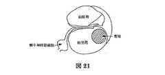
発明の別の実施の形態によると、対象の内耳に流体を配送のための装置は、流体源と流体連通する第1カテーテルと、マイクロ隔壁コネクタを含んでいる。マイクロ隔壁コネクタは、第1カテーテルと連通する埋込み式スピアコネクタと、針を含む埋込み式スピアコネクタと、針を挿入する隔壁を持つ埋込み式ポートコネクタとを含んでいる。装置はまた、埋込み式ポートコネクタを対象の内耳に取り付けるための固定装置を含んでいる。固定装置は対象の岬角骨に取り付けることがでいる。 In accordance with another embodiment of the invention, an apparatus for delivering fluid to a subject's inner ear includes a first catheter in fluid communication with a fluid source and a microseptal connector. The micro septum connector includes an implantable spear connector in communication with the first catheter, an implantable spear connector including a needle, and an implantable port connector having a septum for inserting the needle. The device also includes a fixation device for attaching the implantable port connector to the inner ear of the subject. The fixation device can be attached to the target cape bone.
発明の別の実施の形態によると、対象の体に流体を配送するための装置は、第1隔壁を含む埋込み式流体リザーバと、該埋込み式流体リザーバと流体連通するカテーテルと、該カテーテルに流体連通する第1針とを含んでいる。関連する実施の形態によると、埋込み式流体リザーバとカテーテルの間に細菌ろ過器及び/又は流れ絞り(拘束)器を配設することとしてもよい。また、第1針をカテーテルに付けるためのアンカーを含むこととしてもよく、かつ、アンカーはシリコーンプラグ及び/又は1つ以上の金属リングを含むことができる。他の関連する実施の形態によると、装置はまた、第1針と流体連通するアクセスポートを含んでもよい。アクセスポートは、マイクロリザーバを含む第2隔壁と、該マイクロリザーバと流体連通する第2針を含んでいる。第2針を第2隔壁に付けるためのアンカーをまた含むことができ、アンカーは1つ以上の金属リングを含むことができる。金属リングはシリコーンに埋め込まれてもよい。 According to another embodiment of the invention, an apparatus for delivering fluid to a subject's body includes an implantable fluid reservoir that includes a first septum, a catheter in fluid communication with the implantable fluid reservoir, and fluid to the catheter. A first needle in communication therewith. According to related embodiments, a bacterial filter and / or a flow restrictor may be disposed between the implantable fluid reservoir and the catheter. An anchor for attaching the first needle to the catheter may also be included, and the anchor may include a silicone plug and / or one or more metal rings. According to other related embodiments, the device may also include an access port in fluid communication with the first needle. The access port includes a second septum that includes a microreservoir and a second needle that is in fluid communication with the microreservoir. An anchor for attaching the second needle to the second septum can also be included, and the anchor can include one or more metal rings. The metal ring may be embedded in silicone.
発明の一層の実施の形態によると、対象の体に流体を配送するための埋込み式アクセスポートは、マイクロリザーバを含む埋込み式隔壁と、該マイクロリザーバと流体連通する針を含む埋込み式隔壁を含んでいる。アクセスポートは針を埋込み式隔壁に付けるためのアンカーを含んでもよく、アンカーは、シリコーンに埋め込まれてもよい1つ以上の金属リングを含むことができる。 According to a further embodiment of the invention, an implantable access port for delivering fluid to a subject's body includes an implantable septum including a microreservoir and an implantable septum including a needle in fluid communication with the microreservoir. It is out. The access port may include an anchor for attaching the needle to the implantable septum, and the anchor may include one or more metal rings that may be embedded in the silicone.
発明の別の実施の形態によると、対象の体へ流体を配送するための埋込み式流体源は埋込み式流体リザーバを含むことができ、埋込み式流体リザーバは、少なくとも1つの流体チャンネルと、該少なくとも1つの流体チャンネルと流体連通する隔壁とを含む。 According to another embodiment of the invention, an implantable fluid source for delivering fluid to a subject's body can include an implantable fluid reservoir, wherein the implantable fluid reservoir includes at least one fluid channel and the at least one fluid channel. A septum in fluid communication with one fluid channel.
上で述べた発明の特徴は、添付の図面を参照してなされる以下の詳細な説明を参照することにより容易に理解されるであろう。 The features of the invention described above will be readily understood by reference to the following detailed description, taken with reference to the accompanying drawings, in which:
図1は本発明の実施の形態に従った流体配送システムを示す。この実施の形態の目的において、流体配送システムは、製薬品を例えば、対象の内耳に配送するのに使われる。しかしながら、ここで説明される流体配送システム及び装置は多くの異なったタイプの流体を対象の体の1つ以上の内部領域に配送することに使用されてもよい。図1に示すシステムは、内耳側103部分と中耳側105部分を備える生体適合性の密封されたマイクロ弁101を含んでいる。マイクロ弁101は、蝸牛の岬角骨107又は丸窓を通して、中耳と内耳の間に安全な経路を提供する。この接続は、例えば、鼓室階、前庭、又は中央階までとすることができる。マイクロ弁101は、様々な粘性の流体を配送して機能を治癒させるため、内耳への永久的なアクセスを提供する。マイクロ弁101は、例えば、ポリマー、チタニウム(ドイツ国のクルツ(Kurtz)G.m.b.H.によって生産されるレーザマイクロ加工によって精密カットされたもの)、ニッケルチタン合金又は医用生体材料のいかなる組み合わせのもので作られていてもよい。マイクロ弁101は、内耳での使用において、蝸牛岬角骨107に据えつけられてもよい。同様に、マイクロ弁は内耳丸窓又は半規管に位置してもよい。金属及び/又はポリマーベースのマイクロ弁101と岬角骨107への固着及びシールは、例えば、生体適合性セメント及び/又はねじ付きシャフトにおける機械的継手の使用を介して、かつ、骨同化により達成される。マイクロ弁101と岬角骨107との接続は、例えば、内ねじ及び外ねじを有する管を介してなされる。必要あるいは所望であるならば、マイクロ弁101を岬角骨107から取り外し可能に設けることとしてもよい。 FIG. 1 shows a fluid delivery system according to an embodiment of the present invention. For the purposes of this embodiment, the fluid delivery system is used to deliver a drug product, for example, to the inner ear of a subject. However, the fluid delivery systems and devices described herein may be used to deliver many different types of fluid to one or more internal regions of the subject's body. The system shown in FIG. 1 includes a biocompatible sealed
マイクロ弁101を設置するために、必ずしも必要ではないが、通常、直径がおよそ0.8〜2mm又はそれより大きい孔を岬角骨にあけることが要求される。マイクロ弁101は、カテーテル、リザーバ又はポンプ内にいかなる流体圧が感知されないときに、図10で示されるように自己閉鎖弁とすることができる。マイクロ弁101を表面処理し、あるいは、化学的蒸着その他の方法によって表面にコーティングすることにより、時間がたつにつれて蝸牛内領域で組織が成長し、弁オリフィスが閉塞することを防ぐこととしてもよい。マイクロ弁101はまた、磁石と、鼓室形成術を介して設置される磁気調節システムとを含んでもよい。 In order to install the
マイクロ弁101への流体の配送は、内径が0.5〜2mm(但し、これに限定されるものものではない)の可撓性のカテーテル109を介して通して達成することができる。カテーテル109の一端は、例えば、マイクロ弁101の中耳側105にしっかりと接続してもよい。接続は十分にきつく、カテーテルから中耳への流体の漏れを防ぐことができる。接続は永久的なものとすることとしてもよく、あるいは、外科手術アプローチによって取り外せるものとすることとしてもよい。親水性は粘性流体の配送に好ましいため、管腔(内腔)に親水性を与えるためにカテーテル109の内面を表面処理することとしてもよい。 Delivery of fluid to the
カテーテルの他端はリザーバ113を備えるポンプ111ような流体源に接続されてもよい。同様に、流体源は、ばね作動のピストン、又は、磁石を含んでなり図4に示されるように外部又は内部から磁力を与えることによって作動されるピストンのような受動型アンロードシステムを備えるピストンのようなリザーバ401を含むことができる。カテーテル109はまた、浸透圧ポンプに接続されてもよい。ポンプ111をアクティブ型にすることができ、そのことは、移植蝸牛刺激装置その他の埋込み式プロテーゼと共に使用される電子制御箱のような電子制御箱に径皮的に移送されるエネルギーによってポンプが操作されてもよいことを意味する。ポンプ111はまた、ポンプチャンバ内にロードされる、例えば、ガス他の流体によるエネルギー転送を受ける受動型であってもよい。 The other end of the catheter may be connected to a fluid source such as a
エネルギーをポンプ111に送って流体をリザーバ113からカテーテルを通して内耳まで下側へ移動させ、あるいは、流体をばね負荷リザーバ401を介して移動させると、十分な圧力が得られてマイクロ弁101を開く。いかなるエネルギーや圧力がマイクロ弁101によって感じられないとき、マイクロ弁101を自動的に閉じるようにしてもよく、それによって内耳を中耳に対してシールすることができる。マイクロ弁101の閉鎖は、図10に示すように弁の内耳側に設けたばね1003に取り付けたチタニウム球1001を使用することで行うことができる。しかしながら、流体圧力や圧電のような他の方法を使用してマイクロ弁101を開閉することとしてもよい。 When energy is sent to the
発明の別の実施の形態に従い、図6に示すようにマイクロ弁101をスクリュオン(ねじ込み取付)キャニスタ601に直接しっかりと接続することととしてもよい。これは一度の流体配送を可能にする。キャニスタ601を取り外して詰替を行うこととしてもよく、あるいは、受動型流体配送機能を備える別のキャニスタに取り替えることとしてもよい。 According to another embodiment of the invention, the
上で述べたように、発明に従った流体配送システムは、例えば、移植蝸牛刺激装置のような電子プロテーゼ又は移植装置と組み合わせて使用することができる。これは2通りのやり方で達成することができる。即ち、カテーテルをプロテーゼ又は移植装置と協働する電極に溶着するか、あるいは、体へ流体と電流を平行して配送することによるものである。図2は、発明の実施の形態に従った移植蝸牛刺激装置に溶着される流体配送システムを示す。流体配送システムのカテーテル109はその電極203を通して移植蝸牛刺激装置201に接続される。電極203は、それとカテーテルの合流点205で始まる全長に渡って空洞である。上で説明された弁もまた、この実施の形態において使用可能であることに留意されたい。)電極203の空洞部分はある程度の長さ蝸牛内に続いてもよい。電極203の空洞部分は内耳へ流体を配送する流路として機能する。蝸牛内の電極の部分において、電極203素材に配設された適当なサイズの1つ又は数個のチャンネルにより内耳の流体へアクセスすることが可能になる。流体源を移植装置に接続するカテーテル109は電極203から取り外し可能に、又は取り外すことできないようにすることもできる。取り外すことできないようにしたときに、弁又はスイッチ(図示省略)は、内耳と、側頭骨の他の構造体(中耳(流体、組織又は空気)を含む)との接続も防ぐ。 As mentioned above, the fluid delivery system according to the invention can be used in combination with an electronic prosthesis or implantation device such as, for example, a transplanted cochlear stimulator. This can be accomplished in two ways. That is, by welding the catheter to an electrode cooperating with the prosthesis or implantation device, or by delivering fluid and current in parallel to the body. FIG. 2 shows a fluid delivery system that is welded to an implantable cochlear stimulator according to an embodiment of the invention. The fluid
図3は発明の実施の形態に従う移植蝸牛刺激装置に平行に注入される流体配送システムを示す。平行な配送は、移植蝸牛刺激装置301と流体配送システム305が溶着されないことを意味する。蝸牛に大きな単一の孔又は隣接し分離した2つの孔をあけて電極303と流体配送システム305を別々に先導することができる。この蝸牛孔あけは岬角骨上で互いに隣り合うようにしてもよい。この場合、後部鼓膜切開術又は、移植蝸牛刺激装置電極303と流体配送システム305の両方を同一あるいは隣接する蝸牛岬角骨開口に通すことができる1つの大きな孔をあける手術を含む古典的な外科手術を経て、移植蝸牛刺激装置電極303と流体配送システム305を内耳内に導入することとしてもよい。典型的なアプローチは、岬角骨に対する2つの別個の外科手術アプローチの後に、2つの蝸牛孔をあけることを必要とする。第1外科的アプローチは古典的な後部鼓膜切開術である。第2外科手術アプローチは、Kronenberg教授、Hausler教授及びKiratzidis博士によって説明された、いわゆる、道上アプローチの別形である。後部鼓膜切開術に続いて孔明けがなされた蝸牛孔に電極又は流体配送システムを挿入してもよい。電極又は流体配送システムを道上アプローチに続く蝸牛孔に挿入してもよい。電極又は流体配送システムをまた、丸窓を通して移植することとしてもよい。蝸牛穿孔による1つ又は2つの孔及び丸窓開口を用いて、電極と流体配送システムのすべての順序を入れ替えることは可能である。 FIG. 3 shows a fluid delivery system that is injected in parallel to an implantable cochlear stimulator according to an embodiment of the invention. Parallel delivery means that the transplant
図5は、発明の別の実施の形態に従った流体配送システムを示す。この実施の形態によると、岬角骨弁を用いることなく、カテーテルを直接内耳に挿入することができる。この場合、蝸牛孔があけられてカテーテルがその開口内に一定の距離挿入される。カテーテルを岬角骨上で、例えば、フィブリン糊によりしっかりとシールすることができる。 FIG. 5 shows a fluid delivery system according to another embodiment of the invention. According to this embodiment, the catheter can be directly inserted into the inner ear without using the cape bone flap. In this case, the cochlear hole is opened and the catheter is inserted into the opening a certain distance. The catheter can be tightly sealed on the cape bone, for example with fibrin glue.
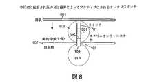
図7は、発明の実施の形態に従って皮下に移植することができるスイッチを示す。様々な実施の形態(ピストン付きのリザーバ、リザーバ及びポンプ、キャニスタ上のねじ、詰替可能及び詰替不可のリザーバ、移植蝸牛刺激装置システムが組み込まれたリザーバ、岬角に弁が設けられ又は設けられていないドラッグデリバリ[薬剤配送]システム等)において、薬剤配送の間に患者が副作用で苦しむ場合、いかなる時にも流体の配送を止める手段を設けることができる。例えば、遠隔計測受信機付きのポンプが設計に含まれているときならばその遠隔計測を介して流体の流れを止めることとしてもよい。受動型の機械的オンオフスイッチ701によってもまた流体を止めることとしてもよい。そのようなオンオフスイッチ701は、例えば、カテーテルの上、リザーバの上、又は弁の上に組み込まれてもよい。スイッチ701は(それが例えば、皮膚直下の頭蓋骨の表面に位置し、また)それが外部からアクセス可能であるならば、それを手動でオン・オフ作動させることができる。スイッチ701はまた、図8に示すように 経皮的又は鼓膜801を通して伝えられる磁気エネルギによって作動可能である。スイッチはまた、鼓膜の小さ開口(鼓室形成)を介して、特別に設計されたツールを弁に挿入することにより、あるいは、該弁に近い中耳内の特定位置に配設されたスイッチ上でオンオフ作動される。この特別位置に設けたスイッチは岬角骨にオーバハングし鼓室形成を介してアクセス可能な金属製部品とすることができる。 FIG. 7 shows a switch that can be implanted subcutaneously in accordance with an embodiment of the invention. Various embodiments (reservoir with piston, reservoir and pump, screw on canister, refillable and non-refillable reservoir, reservoir with implanted cochlear stimulator system, valve at or at cape angle In non-drug delivery systems, etc.), if the patient suffers from side effects during drug delivery, means can be provided to stop fluid delivery at any time. For example, if a pump with a telemetry receiver is included in the design, fluid flow may be stopped via the telemetry. A passive mechanical on / off
薬剤配送システムの様々な実施の形態によると、リザーバはキャニスタ詰替可能であってもよい。図9は、再充填が、例えばリザーバ上に位置する厚い不浸透性の膜を通る又は特別な出口弁を通る治療液を注射することにより行われることを例示する。そのような再充填を局麻に引き続き、かつ、リザーバを覆う皮膚の切込みの後に行うことができる。鼓膜に形成した小さい切込みを介して、リザーバの容器に針を挿入することでもまた再充填を行うことができる。配送システムが、例えば、ばね負荷リザーバであるとき、弁スイッチシステムを使用してリザーバを詰め替えることができる。装置へのアクセスの後に、弁スイッチ901が閉じられ、弁スイッチ902は開いている。例えば針付きスイッチ弁902を通して流体を注入することができ、それによりピストン903を押し戻して、ポンプ流体に負荷をかけてばね905を圧縮する。 According to various embodiments of the drug delivery system, the reservoir may be canister refillable. FIG. 9 illustrates that refilling is performed, for example, by injecting treatment liquid through a thick impermeable membrane located on the reservoir or through a special outlet valve. Such refilling can be performed following the local hemp and after a cut in the skin covering the reservoir. Refilling can also be performed by inserting a needle into the reservoir container through a small notch formed in the eardrum. When the delivery system is, for example, a spring loaded reservoir, the reservoir can be refilled using a valve switch system. After access to the device,
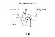
図11は対象の鼓膜を通して流体を配送する流体配送システムを示す。この態様では、ポンプ及び/又はリザーバ111、113は外耳の外に位置し、カテーテルは外耳と鼓膜を横断する。カテーテルの中耳内部分1101は、岬角骨、丸窓又は前庭窓に位置する弁に接続される。カテーテル部分1101のこの接続は、カテーテル管を後方に引っ張って中耳から外耳に向かう力を与えることによって取り外すことが可能である。上で説明された実施の形態におけるように、ポンプ/リザーバがオンオフスイッチ含むことができ、かつ、リザーバを詰替可能にすることとしてもよい。 FIG. 11 shows a fluid delivery system that delivers fluid through the target eardrum. In this embodiment, the pumps and / or
図12−14は対象の体に流体を配送する別の装置を例示する。装置は、液体ポンプ1201(図12で示されるもの)又は流体ポート若しくは流体リザーバ1301(図13で示されるもの)のような流体源を含んでいる。装置はさらにマイクロ隔壁コネクタ1203を含んでいる。マイクロ隔壁コネクタは基端においてスピアカテーテル1205に流体連通し、スピアカテーテル1205は流体源に流体連通している。マイクロ隔壁コネクタ1203は遠位端においてポートカテーテル1207と流体連通する。ポートカテーテル1207は別のカテーテル(図示省略)又は、図14で示されるように、1つ以上の電極若しくは電子プロテーゼ1401と流体連通してもよい。各電極又は電子プロテーゼ1401は、それが1つ以上の出口を持つカテーテルとして一部機能するように、出口を備える1つ以上の流体チャンネル1403を有することとしてもよい。 12-14 illustrate another device for delivering fluid to the subject's body. The apparatus includes a fluid source such as a liquid pump 1201 (shown in FIG. 12) or a fluid port or fluid reservoir 1301 (shown in FIG. 13). The apparatus further includes a
上で説明されるように、マイクロ隔壁コネクタ1203はスピアカテーテル1205を介して埋込み式流体ポンプ、流体ポート若しくはリザーバ又は浸透圧ポンプと流体連通し、かつ、ポートカテーテル1207(このカテーテルは別のカテーテル又は電極若しくは電子プロテーゼ(1401ようなもの)に連結又は流体連通させることができる)を介して対象の体に流体連通する。流体配送装置(ポートカテーテル1207と電極や電子プロテーゼ1401のようなもの)と、流体を動かして配送する装置(流体ポンプ1201あるいは流体ポート1301といったもの)は外科手術手順において対象である人間又は動物に移植できるように設計される。これらの2つの装置の接続はマイクロ隔壁コネクタ1203によってなされる。 As described above, the
図15は発明の実施の形態に従ったマイクロ隔壁コネクタを示す。マイクロ隔壁コネクタは埋込み式ポートコネクタ1501と埋込み式スピアコネクタに1503を含んでなる(これらのコネクタは図15では連結されておらず、図16では接続されている)。埋込み式ポートコネクタ1501は隔壁1505を含み、末端(遠位端)において流体を対象の体の特定位置に輸送するポートカテーテル1207と流体連通することができる。(ポートコネクタ1501は、ポートカテーテル1207と流体連通するとき、図12−14に示されるようにポートカテーテル1207の基端に位置する。)ポートカテーテル1207の末端は、流体が周囲生物組織内に広まるようにするために、1つ以上の開口を持ってもよい。スピアコネクタ1503は針1507を含んで、その末端のスピアカテーテル1105と流体連通することができる。スピアカテーテル1205の基端に向けて流体源が取り付けられる。 FIG. 15 shows a micro bulkhead connector according to an embodiment of the invention. The micro bulkhead connector comprises an embedded
発明の1つの実施の形態では、ポートコネクタ1501の基端と、スピアコネクタ1503の末端は面結合(面と面との結合)ではない。これは、ポートコネクタ1501とスピアコネクタ1503を針1507を介して接合するときにマイクロ隔壁コネクタ1203の平面の間のデッドスペースの創成を防ぐことになる。そのような実施の形態では、スピアコネクタ1503の針1507は隔壁1505を横断するが、針1507の隔壁1505よりも前に位置する部分は流体と体組織に露出される。そのような状況は針1507が隔壁1505に侵入する点においてより良好な組織シールを形成する。さらに、閉じ込められた組織は周囲の組織によって湿潤されいかなる炎症にもうまく応じることができる。組織、帯紋又は筋に針1507を通して上方へスピアコネクタ1503の平端面まで導入することもまた実行可能である。組織を導入することは、ポートコネクタ1501とスピアコネクタ1503の両平端面の間で良好かつ健康な組織が成長することを促進するであろう。図16からわかるように、ポートコネクタ1501と、スピアコネクタ1503は、一端連結されると、周囲生物環境への漏れを生じることなく、安全な流体輸送を可能にする。 In one embodiment of the invention, the proximal end of the
ポートコネクタ1501の重要な特徴は隔壁1505である。隔壁1505は望ましくは、ゴムシリコーンで作られている。ポートコネクタ1501はまた圧力リング1511を含んでもよい。圧力リング1511(又は、他の圧迫装置)は装置に隔壁の特性を与えるためにシリコーンを圧縮する。圧力リング1511は、望ましくは、医療グレードのチタニウムで作られてるが、シリコーン圧縮して円筒状部分とすることができるならばいかなる他のものでもよい。そのような材料は形状記憶ニチノール金属と形状記憶ポリマーを含んでもよい。圧力リング1511をガイド又はガイド機構1513、ストッパ又は他のストップ装置1515及びロック機構1517によってポートコネクタ1501の接続側面に向かって終端させてもよい。細菌ろ過器1509をポートコネクタ1501とポートカテーテル1207の間に設けてもよいし、あるいは設けないこととしてもよい。ポートコネクタ1501はまた、針1507突き刺さることを防ぐためにチタニウムシェルで裏打ちされてもよいリザーバ1521を含むことができる。ポートカテーテル1207の基端は任意にポートコネクタに接着されたシリコーンであってもよい。金属の環境への露出を防止しかつ良好な封入のためにシリコーン層をポートコネクタ1501全体に堆積させることとしてもよい。堆積は、適切なシリコーンゴム溶液中にポートコネクタ1501を浸せきさせることによって実行してもよい。 An important feature of the
スピアコネクタ1503をシリコーン、エポキシ又は発明に必要又は有益であると考えられる他のいかなる生体適合材で作ることとしてもよい。適切なサイズ、材質及び形状の(番号1507で示すような)医療針をその両端が型からはみ出るようにして型に挿入する。シリコーン及び/又は医療グレードのエポキシの射出成形は針のコアをしっかり囲い込む。カテーテル(スピアカテーテル1205ようなもの)が針の一端上に導入され、シリコンが加えられ硬化されてスピアコネクタをシールする。針1507が隔壁1505を貫くように針の先端を側部に対して鋭角に傾斜してもよい。流体を移送する針1507の孔は針の端部にあってもよく、あるいは針の先端から小さい距離の位置に位置する針の側部上にあってもよいことに留意されたい。
上で述べたように、マイクロ隔壁コネクタ1203はまた、針1507で隔壁1505を突き抜く前に、針1507とポートコネクタ1501を一列に並べるためのガイド又は案内機構(1513ようなもの)を含めてもよい。ガイド又は案内機構1513は針1507の先端を隔壁1505の中心に一列に並べることを可能にする。ガイド又は案内機構1513はまた、針1507が上、下、又は横方向に大きくずれることを防ぐ。そのような大きなずれがあると、針1507の先端はポートコネクタ1501の内壁の中に位置されることになり、流体の流れを阻害する。 As noted above, the
スピアコネクタ1503とポートコネクタ1501がそれらの平面で融合することを防ぐためにストッパ又は停止装置1515を使用することとしてもよい。ストッパ又は停止装置1515は、針1507が完全に挿入されたときでさえ、針1507の一部が体液にさらされることを可能にする。したがって、ストッパ又は停止装置1515は、スピアコネクタ1503とポートコネクタ1501が接続されたときに、それらの平坦な面の間にデッドスペースを作らないようにする。但し、そのような平坦な接続が発明に有益な場合は別である。これは、例えば、常時感染病巣を作らないように抗生物質をコーティングする場合である。 A stopper or stop
ロック機構1517は、通常の体運動と使用による応力下でマイクロ隔壁コネクタ1203の安定性を促進するためにマイクロ隔壁コネクタ1203に含まれてもよい。ロック機構1517は、上で説明された1つ以上の部品を交換することができるように裏返し可能にすることができる。 A
いったん製造され適切な方法によって殺菌されると、外科医は、針1507を隔壁1505に通し、そしてオプションとして、マイクロ隔壁コネクタ1203をロック機構1517にロックすることによって、ポートコネクタ1501とスピアコネクタ1503を接続することができる。ポートコネクタ1501をスピアコネクタ1503に接合する前に、それぞれのコネクタを別々に薬剤流体で満たすこととしてもよい。このように別々に充填することで、接続の前に両方の埋込み式コネクタ1501,1503の良好なプライマー効果を与える。スピアカテーテル1205の充填は、ポンプ(通常、ポンプ隔壁を通して)、隔壁とリザーバを備えるポート、又は浸透圧ポンプを満たすことによって達成されてもよい。また、装置のいかなる充填及びプライマー処理が生じる前に、埋込み式コネクタ1501と1503の接続が行われるということであってもよい。 Once manufactured and sterilized by an appropriate method, the surgeon connects the
埋込み式コネクタ1501と1503の一方又は両方の取外し又は取替があるならば、外科手術的な介入は、成長組織の慎重な除去、ポートコネクタ1501周りの膜封入の慎重な除去、及び両コネクタを互いに後方に引っ張ることによりスピアコネクタ1503を取り外すことを含んでもよい。この段階において、ポートコネクタ1501とスピアコネクタ1503のどちらか一方又は両方を興味の生物環境に置くこととしてもよい。これは、上に説明した通常の方法でシステムをプライマー処理した後に、することとしてもよい。いったん取り替えられて置かれると、ポートコネクタとスピアコネクタの接続は、ポートコネクタ1501とスピアコネクタ1503を(恐らくガイド1513を使用して)係合させ、隔壁1505を差し込み、かつ、望まれるならば、ロック機構1517を介してメカニズムをロックすることにより達成される。 If there is a removal or replacement of one or both of the
流体を対象の内耳に提供するために図12−16に関して説明されるシステムを使用することができる。図17は発明の一層の実施の形態に従った対象の内耳に流体を配送するための装置を示す。内耳は蝸牛と半規管(図示省略)を含んでなる。流体配送は、そのように望まれるならば移植蝸牛刺激装置の電極を通して達成されてもよく、又は、内耳へ部分的あるいは完全に挿入された補強流体配送カテーテル若しくは丸窓膜に対して並置されたカテーテルを通して達成されてもよい。そのような応用が望まれるとき、コネクタアセンブリを部分的に埋めるために頭蓋骨の表面に骨のくぼみを形成することとしてもよい。コネクタを埋設することは、頭皮下でのコネクタの突起を防ぐことができる。 The system described with respect to FIGS. 12-16 can be used to provide fluid to the inner ear of the subject. FIG. 17 shows an apparatus for delivering fluid to the inner ear of a subject according to a further embodiment of the invention. The inner ear comprises a cochlea and a semicircular canal (not shown). Fluid delivery may be accomplished through the electrodes of the implanted cochlear stimulator if so desired, or juxtaposed against a reinforced fluid delivery catheter or round window membrane partially or fully inserted into the inner ear. It may be achieved through a catheter. When such an application is desired, a bone recess may be formed in the surface of the skull to partially fill the connector assembly. Embedding the connector can prevent the protrusion of the connector under the scalp.
図17の実施の形態に従って、スピアコネクタ1205及び針1507は流体を隔壁1701に提供するのに使用される。隔壁1701は、対象の内耳又は岬角骨1703に外科手術により埋め込まれるために適切なサイズと形のものとすることができる。隔壁1701を内耳か岬角骨1703に固定するために金属帯板や表面のくぼみを骨への取付要素1705として使うこととしてもよい。例えば、岬角骨1703に2mm又はそれより小さい内腔を穿孔した後に、該骨に円錐ベッドを作ることとしてもよい。簡単な円錐隔壁(番号1701で示すようなもの)を蝸牛管1708の開口に配設し蝸牛岬角骨1703に据えつけることができる。そうすることで、隔壁1701はスピアコネクタ1205との接続を通して流体を配送するのに利用可能な状態に残ることができる。そのような構成において、流体配送のために半規管(胞嚢を含む)にアクセス可能である。さらに、図17の構成はまた、上の実施の形態に関して説明した目的のための圧力リング1707とストッパ1709を含んでもよい。 In accordance with the embodiment of FIG. 17,
図12−17の流体配送システムは容易かつ迅速にコネクタに接続される。接続はそれが長期間に及ぶものであっても漏出が防止され、流体配送システムを容易に外すことができる。取外しの際、ポートカテーテルをシールされた状態のままに残すことができ、流体配送システムを異なる別の又は同じ流体駆動装置に再接続することができる。移植されたポートカテーテルを移植後何年も使用するために移植したまま残すことができ、一方、駆動装置を取り外すこととすることができる。装置が電極と共に使用され、流体駆動装置が取り出されるならば、電極を取り除く必要はない。さらに、流体駆動装置を後日電極に再接続することができる。望まれるならば、流体配送モジュールを単一のポートカテーテルに平行に接続することができる。 The fluid delivery system of FIGS. 12-17 is easily and quickly connected to the connector. Even if the connection lasts for a long time, leakage is prevented and the fluid delivery system can be easily removed. Upon removal, the port catheter can remain sealed and the fluid delivery system can be reconnected to a different or the same fluid drive. The implanted port catheter can be left implanted for use for years after implantation, while the drive can be removed. If the device is used with an electrode and the fluid drive is removed, there is no need to remove the electrode. Furthermore, the fluid drive can be reconnected to the electrode at a later date. If desired, the fluid delivery module can be connected in parallel to a single port catheter.
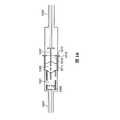
図18と19は発明の別の実施の形態に従ったカテーテルを例示する。カテーテル1801は、対象の体に部分的又は完全に挿入されるように設計される。例えば、カテーテル1801を蝸牛孔を通して内耳(鼓室階、前庭階、又は半規管)に挿入して薬剤を内耳流体まで配送することができる。カテーテル1801の無傷挿入はカテーテルの機械的特性に依存する。機械的特性は、階段構造の彎曲周りに無傷挿入を可能にするようなものでなければならない。 18 and 19 illustrate a catheter according to another embodiment of the invention. The
埋込を容易にするために、カテーテル1801を円錐又は円筒形とし、断面を丸又は楕円し、かつ、丸まった先端1811を有するようにしてもよい。カテーテル1801をポリマーベースとし、ポリマーは良好な可撓性ためにシリコーンを含むことができる。代わりに、カテーテルは生分解性ポリマーで作られていてもよい。同様に、カテーテル1801は引っ張られると縮む材料で作られていてもよい。 To facilitate implantation, the
カテーテル1801はオプションとして1本以上の補強ワイヤ及び/又は装置を押して埋込みをよりよく行えるように硬質ポリマーフィラメント、金属又は合金で作ったリボン1807を含んでもよい。カテーテル1801はまた、挿入の深さを示すためにポリマーの表面に設けるマーカ1805及び/又は蝸牛孔を閉じるためにそれに通す調整可能なブロッカ(閉塞物)を含んでもよい。カテーテル1801の実施の形態は、流体に自由な流れを与えるための二重(2つの)出口1809を含むことができ、これらの出口1809を反対方向に設けることができる。同様に、カテーテル1801は、流体又は薬剤濃度分布プロファイルを制御するために、カテーテル本体の中心に(又は縁に向かう)1個以上のチャンネル1803、1817、1819を含んでもよい。カテーテル1801はまた、挿入を機能アップするために潤滑コーティングを含んでもよい。同様に、カテーテル1801を感染防止のための皮質ステロイド及び/又は抗生物質でコーティングすることとしてもよい。
関連する実施の形態において、カテーテル1801は、対象の体(の部位)に位置し対象がアクセスすることができる(磁石か機械的な圧力によって作動される)オンオフスイッチ又は弁1813を有することができ、対象の体の部位は、皮膚の上、あるいは、内耳への流体配送に関して使用される場合は、流体給送リザーバと内耳内の部分の間の頭蓋骨上である。弁又はスイッチ1813は流体の逆流を防ぐために使用することができる。カテーテル1801は、挿入をより容易かつ精確にするためにさらに可動ストッパ1815を含むことができる。 In a related embodiment, the
カテーテル1801は流体配送のための内部チャンネル1803を備えるように設計されている。例えば、内耳への流体の局所的配送は蝸牛神経節細胞の機能特性を維持し、樹状突起を再生し、残っている聴力機能を保存し聴力損失の進行を抑止する。応用は、炎症を押さえる皮質ステロイド、硬化症や組織の成長を抑止する薬剤、耳鳴りやめまいに対する目新しい治療に使用することができる薬剤の配送を含むことができる
流体の配送は、蝸牛内の位置まで導かれたカテーテルに形成された空洞チャンネル1803を介してなされる。カテーテルに1801には1つ以上の出口1809が含まれる。チャンネル1803は、薬剤を外部に圧送する隔壁を含む内部マイクロポンプ又はポートに接続されてもよい。カテーテル1801の中心近く、又は、カテーテル1801の中心から縁の方へずれた位置に配設された空洞チャンネル1803はリバースモールディングによって成形される。これは、射出成形の前に、型に位置ホルダが含まれてもよいことを意味する。射出成形の後に位置ホルダは次に取り外され、空洞チャンネルはその位置に残される。流体配送チャネルの出口1809は基端及び/又は遠位端に位置されてもよい。流体配送のための出口1809は、時間経過に伴う組織の成長や出口の閉塞を防ぐために緩効性生物活性剤のリングでコーティングされてもよい。The
流体配送のための各出口1809は、180度離れた2個の出口チャンネル1817,1819を含んでもよい。これらの2個の出口チャンネル1817と1819は、それらが直線をなすように、あるいは、互いにオフセットするように接続されてもよい。流体を内耳へ配送するために設計されたカテーテル(図19で示される)において、2個の出口チャンネルを180度離す目的は、1個の出口チャンネルがいつもリンパ周囲液に面することを確実にすることである。出口1809の1個の出口チャンネルが基底膜又は鼓室階の側壁に面する状態で、出口チャンネルが閉塞する可能性が存在する。各出口チャンネルはマイクロマシン加工のチタニウムと、皮質ステロイドを加えたシリコン(薬剤溶離液)の覆い(絶縁保護コーティング、どぶ漬け、プラズマ蒸着)をチタニウムマイクロ管上に付けた金属とで形成されてもよい。そのような表面の変形例は出口1809の閉塞を防ぐことを意図する。 Each
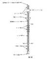
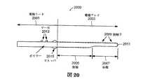
図20は発明の別の実施の形態に従った埋込み式電極を示す。電極2000は電極リード2001と、電極アレイ2003を含んでなる。電極アレイ2003は前端2007と後端2005を含んでいる。電極アレイ2003は、前端2007の第1接触子2009から後端2005の最後の接触子までの距離として定められる。電極2000はポリマーで作られており、該ポリマーはそれに埋め込まれあるいはその上に堆積されたワイヤと接触子2009を備える。ポリマーはシリコーン、ふっ素化ポリマーその他の生体適合材であってもよい。 FIG. 20 shows an implantable electrode according to another embodiment of the invention. The
鼓室階外側壁に設置するように設計されたほとんどの移植蝸牛刺激装置電極の延伸長さは約16mmに制限されている。通常、鼓室階の電極の挿入深さは約23mmに制限される。鼓室階外側壁に沿って23mm挿入された16mmの電極延伸長は蝸牛において限られた音周波数領域と帯域幅をカバーする。電極が内側壁に向かって部分的に変位されると、周波数領域は増加するが、いくつかの電極が外側壁にいくらか接近しているので、いまだ完全な帯域幅の部分のままである。26mm以上の電極範囲が外壁に沿って28〜31mm挿入されている状態で、蝸牛のほぼ完全な帯域幅が第1蝸牛回転における蝸牛神経節細胞及び/又は第2旋回の軸索突起において刺激される。深く挿入することで、電極アレイの1番目と最後の接触子の範囲から外れる空間区域を刺激するために電流の広がりは必要とされない。電極の深挿入に関する利益の前提条件は、ベースから頂点において最小の挿入外傷である。 The extension length of most transplanted cochlear stimulator electrodes designed to be installed on the outer wall of the tympanic floor is limited to about 16 mm. Usually, the insertion depth of the tympanic floor electrode is limited to about 23 mm. An electrode extension length of 16 mm inserted 23 mm along the outer wall of the trumpet floor covers a limited sound frequency region and bandwidth in the cochlea. As the electrodes are partially displaced toward the inner wall, the frequency domain increases, but still remains part of the full bandwidth as some electrodes are somewhat closer to the outer wall. With the electrode range of 26 mm or more inserted 28-31 mm along the outer wall, the almost complete bandwidth of the cochlea is stimulated in the cochlear ganglion cells and / or the second swirling neurites in the first cochlear rotation The With deep insertion, no current spread is required to stimulate a spatial area outside the range of the first and last contacts of the electrode array. A benefit precondition for deep electrode insertion is minimal insertion trauma from the base to the apex.
電極2000は、蝸牛内での導入に必要な力を減少させる特性を持つように設計される。電極挿入力を減少させかつ電極たわみ度を増大させると、鼓室階壁を裏打ちする軟組織に加えられる外傷の量が減少する。挿入による外傷を最大に減少させることは、激しい聾に苦しみ同側性の耳に補聴器を使用しているかもしれない患者、あるいは、補聴器を使用せずに低周波音の覚知はできるが聞き取ることが不十分で一部の聴力しか残っていない患者にとって最も有益である。電極外傷を最小にし続けることへの関心は、今日移植を受けた患者が装置の交換又は機能を喪失した神経経路を回復する装置の追加を受けるかもしれないという事実によって構成される。そのような神経経路が電極挿入の間に機械的に妨害されるならば、経路は永久に破壊されるであろうということが高く見込まれる。
移植蝸牛刺激装置電極は、内耳(鼓室階か前庭階)を介し、らせん形の蝸牛を保護する骨の表面にあけられる孔を介して通常挿入される。聴力が一部残っているならば、挿入の深さを音を聞き取ることができるところの下の領域に制限することに興味がもたれる。電極2000上のストッパ2015は、挿入深さを予め定められた固定値、例えば、20mm(但し、20mmに限定されるものではない)に制限することができる。20mmは蝸牛の約1旋回に相当する。ストッパ2015は、挿入が蝸牛孔を超えてなされることを防ぐ垂直壁を持つように設計される。ストッパ2015が内耳の外部骨にアプローチするとき外科医が蝸牛孔を見ることができるようにストッパ2015にスロットを設けることとしてもよい。別の実施の形態では、ストッパ2015は蝸牛孔に栓をする円錐形である。ストッパ2015をまた、電極2000の上位領域から下方に移動するスライダとすることもできる。 The implanted cochlear stimulator electrode is usually inserted through the inner ear (trum floor or vestibular floor) and through a hole drilled in the surface of the bone that protects the helical cochlea. If some hearing remains, it is interesting to limit the depth of insertion to the area below where the sound can be heard. The
電極2000の挿入深さは予定された値に制御され制限されてもよい。予定された挿入深さ値は患者の聴力図に基づくことができる。聴力図が2000Hzまで意義のある残聴(例えば、50dB以上)を示すならば、外科医は挿入深さを16mmに制限することを選ぶことができる。電極の前端からストッパ2015まで挿入されプレカットされた生体適合性の無菌チューブを使用することで挿入深さの制限をすることとしてもよい。長さ24mmの電極(電極先端からストッパ壁までの長さ)の前面において十分な厚みを有する長さ4mmの管は挿入深さを20mmに制限するであろう。 The insertion depth of the
他のデザインと電極2000を区別するものは電極アレイ2003上の前端2007と後端2005の存在である。前端2007は後端2005よりもはるかに薄い。1つの実施の形態では、電極2000の前端2007は電極長さの1/4〜1/2に渡る。電極2000の前端2007のバルク密度は後端のバルク密度の約1/2であってもよい。この設計において電極2000はその延伸方向に一様に連続するものではなく、固定直径でも一定断面でもないことが理解される。むしろ、電極2000はその断面形に関して不連続である。この不連続性は前端2007の範囲と電極アレイ2003の後端2005の始まりを定める。前端2007は、アレイをコイル巻状の鼓室階の上向きらせん形状にそって押し回すために必要な挿入力と曲げ力が小さくなるように設計されている。後端2005は、必要なときに深い挿入を達成するために電極を最大限押しやすくするように設計される。押しやすさは電極の設計に重要である。なぜならば、押しにくい電極は、その先端2011を前方へ移動させることがでずに蝸牛孔の周りで崩れるであろう。電極2000の挿入を容易にするために、装置の先端2011を薄くし、尖りのない丸いものとすることができる。さらに、電極アレイ2003の前端2007と後端2005を先細りしてもよい。この意味で、先細りとは、前端2007と後端2005の断面積が連続的に変化することを意味する。 What distinguishes the
電極全長に渡って8個以上の接触子2009がポリマー基板に埋め込まれ又は基板上に置かれている。電極移植を受けた患者が人の話すことを理解できるような漸近的な性能に達するのに必要である最小限の接触子2009の数は、現在のところ8つである。接触子2009はプラチナ(白金)、プラチナインジウム(PtIr)、又はインジウム酸化物で作られていてもよい。接触子2009は丸若しくは楕円形であってもよく、又は丸いエッジを持った長方形であってもよい。丸いエッジは電極接触子の縁における電流密度を減少させる。接触子2009の表面の縁の電流密度は、通常、金属表面の初期の接触子溶解の原因となる。接触子2009は、プラチナイリジウムワイヤの先端を燃焼させることによって作られた球体のボールとすることができる。それぞれの接触子2009は単一の、又は、対にされた接触子であってもよい。1つの実施の形態では、対の接触子と、単一の接触子の組み合わせが使用される。前端2007上に位置する接触子は対ではなく(単一で)、後端2005に位置する接触子2009は対にされる。この様にして、電極の後端2005の押しやすさが維持されるとともに、前端2007のたわみ度は保持される。 Eight or more contacts 2009 are embedded in or placed on the polymer substrate over the entire length of the electrode. Currently, the minimum number of contacts 2009 required to reach asymptotic performance so that patients undergoing electrode implantation can understand human speech is eight. The contact 2009 may be made of platinum (platinum), platinum indium (PtIr), or indium oxide. Contact 2009 may be round or oval, or rectangular with rounded edges. The rounded edge reduces the current density at the edge of the electrode contact. The current density at the edge of the contact 2009 surface usually causes the initial contact dissolution of the metal surface. Contact 2009 can be a spherical ball made by burning the tip of a platinum iridium wire. Each contact 2009 may be a single or paired contact. In one embodiment, a combination of a pair of contacts and a single contact is used. The contacts located on the
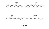
各接触子2009は、ポリマーマトリックスを通って電極2000を形成する絶縁された一本のワイヤ(図22で示される2201、2203、2205、又は2207)に電気的に接続される。電極ワイヤ2201、2203、2205、又は2207は直径で最小15ミクロンまで薄くされる。ワイヤを薄くすることで挿入力を小さくすることができるからである。ワイヤ2201、2203、2205、又は2207は、望ましくは、図22で示されるように小さく曲がった(波状)形状とする。曲がったワイヤはまっすぐなワイヤよりもはるかに可撓性であり、かつ、はるかに少ない力で曲がることができる。曲がったワイヤの曲がり頻度(周波数)、曲がりの度合い(振幅)及び形状は挿入力を最小にするために選択される。 Each contact 2009 is electrically connected to a single insulated wire (2201, 2032, 2205, or 2207 shown in FIG. 22) that forms an
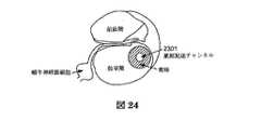
図23は発明の別の実施の形態に従って対象の体に流体を配送するための埋込み式電極アレイを示す。この実施の形態によると、埋込み式電極2300は流体配送のための内部チャンネル2301を備えるように設計されている。例えば、移植蝸牛刺激装置電極(図24を参照)が存在する内耳への流体の局所的配送は、蝸牛神経節細胞の機能的特性のみならず該細胞の数を維持し、樹状突起を再生し、残聴力の保存を促進することができる。応用例は、耳鳴りとめまいのための新規な治療はもちろん、炎症と階内組織の成長を防ぐためにコルチコステロイドの配送を含むことができる。したがって、移植蝸牛刺激装置に流体を配送する機能を含むことは移植蝸牛刺激装置の設計上の貴重な要素である。 FIG. 23 shows an implantable electrode array for delivering fluid to a subject's body according to another embodiment of the invention. According to this embodiment, the
流体配送は、階内の位置まで導かれる電極に形成した空洞チャンネル2301を介してなされる。電極接触子2309の間又はその近くに1つないし数個の出口2307があってもよい。空洞チャンネル2301は内部のマイクロポンプ又は薬剤を外部に圧送するための隔壁を含むポートに接続されてもよい。マイクロポンプ又はポートは移植ハウジングの近くに位置してもよい。空洞チャンネル2301を電極2300の中心の近くに、あるいは、中心から偏心した縁寄りの位置に作る方法はリバースモールディングを含む。リバースモールディングにおいて、ここでも内部空洞チャンネル2301を形成するために、注射成形の前に位置ホルダがモールド内に含まれている。注射成形の後に、位置(場所)ホルダは取り外され、空洞チャンネルはその場所に残される。 Fluid delivery is through a
電極アレイ2300上に位置する接触子2309の近辺又はそれらの間において流体配送チャネル2301のための1つ以上の出口2307を設けてもよい。時間がたつにつれて出口において組織が成長し出口が閉塞することを防くために、流体配送出口2307を生理活性剤のリングでコーティングすることとしてもよい。 One or
図25は図23の電極アレイの流体配送出口を示す。それぞれの流体配送出口2307は、互いに180度離れた2個の出口チャンネル2317,2319を含む。これらの2個の出口チャンネル2317,2319は直線上に接続されるか、あるいは、オフセットした状態に配設されるが、いずれの場合でも互いに180度離れている。移植蝸牛刺激装置用の電極に180度離れた2個の出口チャンネル2317,2319を設ける目的は、1個の出口チャンネルがいつも薬剤流体に面しているようにするためである。出口2307の1個の出口チャンネルが基底膜又は鼓室階の外側壁に面している場合、出口チャンネルが閉塞する可能性がある。流体配送出口2307は、配送薬剤がチャンネル2301を介して圧送されないときに開口の閉塞を防ぐために、潤滑コーティングを含み薬理剤でコーティングされたチタニウムその他の金属で作られていてもよい。コーティングされた流体配送出口2307は電極のシリコーンに埋め込まれている。 FIG. 25 shows the fluid delivery outlet of the electrode array of FIG. Each
図26は発明の一層の実施の形態に従った埋込み式プロテーゼに使用する電極を示す。この実施の形態において、移植電極2600は電極アレイ2613と電極リード2611を含む。電極リード2611は、電子装置を含む金属又はセラミック製のハウジング2601に電気的に接続されている。電子装置は電極接触子に送られる電流パルスを発生させる。電流パルスはポリマーマトリックスに埋め込まれたワイヤを通って接触子にたどり着く。電極リード2611は直角部で任意に終端させてもよい。 FIG. 26 shows an electrode for use in an implantable prosthesis according to a further embodiment of the invention. In this embodiment, the transplant electrode 2600 includes an
蝸牛内刺激モデル及び動物EABRデータは、鼓室階の内壁の近くに置かれる電極アレイが移植のノイロ刺激に有益であろうことを示す。そのような電極は蝸牛軸周囲(ペリモディオラー)電極と呼ばれる。蝸牛軸周囲電極は心理音響しきい値を下げ、刺激のダイナミックレンジを増加させ、チャネル相互作用を減少させるというコンセンサスがある。チャネル相互作用は個々の電極からのフィールドオーバラップによって引き起こされてもよい。蝸牛軸周囲アレイから期待される一層の潜在的利益は、移植装置を駆動する消費電力を減らし、患者の副作用を減らし、革新的な刺激計画をなすことができ、よりよい場所周波数コーディングを含むことである。より多くの電極を有効に使用することができる。 Cochlear stimulation model and animal EABR data show that an electrode array placed near the inner wall of the tympanic floor would be beneficial for transplant neuro stimulation. Such an electrode is called a cochlear axis (perimodiolar) electrode. There is a consensus that the cochlear axis electrode lowers the psychoacoustic threshold, increases the dynamic range of stimulation, and reduces channel interaction. Channel interactions may be caused by field overlap from individual electrodes. A further potential benefit expected from a cochlear axis array is to reduce power consumption driving the implant device, reduce patient side effects, make innovative stimulus plans, and include better location frequency coding It is. More electrodes can be used effectively.
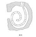
図27−30は発明の別の実施の形態に従う埋込み式電極アレイを示す。この実施の形態によると、電極は、図29に示すように鼓室階の上向きにらせん状に巻いたキャビティの内壁に向かって変位されるように設計される。電極2700の前端2707は、図23に従って説明したものと変わらない。電極2700の前端2707は最小の挿入力で鼓室階の深部浸透を容易にする。しかしながら、電極の後端2705は変更されている。電極2700の後端2705は挿入のために結合する2つの部分(セグメント)に区分される。電極2700を完全に挿入した後、電極アレイの後端2705に位置する2つのセグメント2711,2713は、電極を含んでなるセグメントに引き戻し動作を与えることで分離される。この実施の形態では、2つのセグメント2711,2713は電極2700の前端2707と後端2705の合流点において接続されたままで残っている。2つのセグメント2711,2713はまた、移植蝸牛刺激装置と共に使用されるとき、中耳内の位置において接続された状態で留まっている。2つのセグメント2711,2713は上記2つの位置の間において離脱される。 FIGS. 27-30 illustrate an embedded electrode array according to another embodiment of the invention. According to this embodiment, the electrodes are designed to be displaced toward the inner wall of the cavity spirally wound upward as shown in FIG. The
理解を容易にするために、2つのセグメントを電極ブランチ2713と拘束アーム2711と呼ぶ。2つのセグメント2711,2713は、全挿入過程の間、接続されたままで残っている。セグメントを接続する好ましい方法は、電極ブランチ2713上に成形されたレールを拘束アーム2711上に成形したスロットに圧力により係合させることである。移植蝸牛刺激装置では、セグメント2711と2713は、電極ブランチの一部を蝸牛軸に押し当てるように位置させ、あるいは蝸牛軸の近くに位置させるために後に離脱させる。電極と拘束アームが所定位置に置かれた状態の人間の側頭骨からの蝸牛を図29に示す。 For ease of understanding, the two segments are referred to as an
拘束アーム2711はその質量中に、かつ、その全長に沿ってプラチナ(Pt)又はプラチナイリジウム(PtIr)リボン又はワイヤ2715を含むことができ、拘束アームの剛性を増し、あるいは減少させるために焼きなしを行ってもよく、また、行わなくてもよい。拘束アーム2711の剛性をそのようにコントロールすることは移植蝸牛刺激装置において重要である。なぜならば、電極ブランチ2713にレトロ位置決め技術を用いて電極ブランチ2713を蝸牛軸により近く変位させときに、十分な剛性を維持すると共に良好な挿入特性(たわみ性)を維持するためである。拘束アーム2711は柔らか過ぎるとレトロ位置決め技術を使用する間に座屈するであろう。 The
リボン2715の形は、(図28で示されるように)長さ幅比が2:1である長方形であってもよい。リボン2715の向きは、短い方の長さの向きが中間部に向いている(外壁から内壁へ)ようにすることができる。移植蝸牛刺激装置のリボン2715のそのような向きは、電極アレイ2703の階の底部から頂点に向かう運動を促進させると共に、アレイの上位方向への、即ち、基底膜及びコルチ器官のこわれやすい組織の方に向かう運動を抑える。リボン2715の長方形形状のさらなる利点は、挿入の間に電極接触子が蝸牛軸に面した状態を維持することである。ほぼ長方形のPtIrリボン2715は、拘束アーム2711を形成するシリコーンマトリクスに対するカッティングを減少させるために丸まった角を有することとしてもよい。拘束アーム2711の金属コアは、拘束アーム2711の発明にとって全体的又は部分的に必要な可撓性又は剛性を増加させるために全体的又は部分的に変更されてもよい。リボン2715の変更は、金属の加熱、化学的及び機械的処理を含むことができるが、それに限定されるものではない。拘束アーム2711の組成は金属とシリコーンの組み合わせに制限されるものではなく、テフロン(登録商標)ような他の生体適合ポリマーを拘束アームの概念に関して使用してもよいことが理解される。 The shape of the
電極2700は、移植蝸牛刺激装置と共に使用されるとき、連続して挿入されてもよく、次に、電極2700は内壁に向かって置かれる。第1フェーズにおいて、接続された2つのセグメント2711,2713を備える電極アレイ2703は鼓室階の外壁に沿って挿入される。第2フェーズでは、望ましくは鼓室階の基底旋回部に相当する電極アレイ2703の後端2705部分は、鼓室階の内壁の近くに、あるいは、該内壁に接続するように置かれる。この部分はここにおいて、蝸牛軸周囲(周り)部分と呼ばれる。蝸牛軸周囲部分は望ましくは蝸牛基底旋回部に相当する。なぜならば、ここに電気刺激を行いやすい多数の神経要素が位置するからである。これらの神経要素(蝸牛神経節細胞)は最も多くより基部に近い電極刺激の利益を得るであろう。電極ブランチ2713の残りの蝸牛内部分は深挿入部と呼ばれる。深挿入部は鼓室階に深く挿入されるように設計されるが、それはいかなる自発的行為によっても内壁上に置かれない。 The
セグメント化された電極アレイ2703を蝸牛の鼓室階へ完全に挿入することに続いて、拘束アーム2711は、外科医と、鑷子やピンセットような何らかのマイクロツールによって蝸牛孔の後方(蝸牛の外側)に静的に保持される。電極ブランチ2713は次に拘束アームから外されて、階から引っ込められる。蝸牛からの電極アレイ2703をこのように僅かに引き出すことは、2つのセグメントが一点に集まる点での結合を除き、電極ブランチ2713と拘束アーム2711を結合を有効に外す。前記一点に集まる点において2つのセグメント2715は、例えば、アメリカ合衆国ニューヨーク、マウントヴァーノン(Mount Vernon)のメドワイヤ・シグマンド・コーン・コープ(Medwire Sigmund Cohn Corp)によって供給されるようなPtIr80−20%で作った金属ロッドかリボン2715を介して互いに取り付けられていることに注意することが重要である。1つの実施の形態では、ワイヤ又はリボン2715の端部は電極ブランチ2713のシリコーンの空洞内に収まっている。レトロ位置決め技術の鍵は、拘束アーム2711のコア内のそれほど可撓性でないリボン2715及びワイヤと、より可撓性の電極ブランチ2713との共同である。 Following the complete insertion of the segmented
電極2700の重要な要素は電極が区分(セグメント化)されていることである。設計の別の重要な要素は任意(オプション)であり、これにより、挿入を容易にするために2つのセグメント2711と2713が堅固に連結される。堅固で、しかも、取り外し可能な接続はいくつかの方法によって確立されうる。セグメント接続の1つの方法は、互いに係合する寸法のレールとスロットを介することである。電極ブランチ2713と拘束アーム2711は、製造時に圧力による噛合わせとすることができる。シリコーンの抱き合わせは、挿入の間に電極と拘束アームの接続状態を維持する。 An important element of
2つのセグメント2711と2713を接続する別の設計方法は、包体を介することである。そのような設計が採用されるならば、包体は丸又は楕円であってもよい。電極の係合は図示された設計に制限されることなく、また、電極の接続、挿入、接続の取り外し及び位置決めに有益ないかなる係合も実行可能であることが理解される。さらに別の方法によると、2つのセグメント2711,2713は、数分間の挿入時間内に内耳の流体に溶けるヒドロゲルで接続されてもよい。また、外すことができる2つの異なるシリコーンの結合により2つのセグメントを接続してもよい。 Another design method for connecting the two
移植装置の交換が必要となったときに電極アレイ2703の2つのセグメント2711,2713が容易に外されるように、電極セグメント2711,2713は合流点を有する。レトロを位置決めの際に、拘束作動はもちろんのこと、接続を外すことができるように、2つのセグメント2711,2713は、拘束アームから出て来て電極ブランチ2713に成形された傾斜したシリコーンキャビティ内に適当に嵌着又は遊嵌されるむき出しのPtIrリボン2715部によって接合されてもよい。再手術の場合に、十分な力で拘束アーム2711を後方に引っ張ることにより、2つのセグメント2711と2713をそれらの合流点においてずらすことができ。キャビティをアレイの軸に平行にすることとしてもよく、あるいは、レトロ位置決めに抵抗を与えるように傾けてもよい。拘束アーム2711の背骨として使用されるリボン又はワイヤ2715は、鋭いエッジをなくすためにボール状端部とされてもよい。 The
電極アレイ2703の2つのセグメント2711,2713を一緒に蝸牛の外に取り付けてもよい。そのような取付は、拘束アーム2711に関連する電極ブランチ2713の移動を防ぐために有利である。移植蝸牛刺激装置に対する電極ブランチ2713の移動は術後に電極ブランチ2713と蝸牛軸の接続を解き放すことができる。そのような実施の形態において、図30においてより明確に見られるように2つのセグメント2711,2713を閉鎖可能なチタニウムクリップ2717を用いて取り付けることとしてもよい。 The two
上で説明した電極にはいくつかの利点がある。まず最初に、移植蝸牛刺激装置においては、電極の前端の設計に因り、最小の力で電極の部分を蝸牛に深く、頂点まで挿入させてもよい。さらに、望ましくは蝸牛の第1旋回部に相当する電極の部分を内耳腔の内壁に向けて、あるいは内壁まで変位させてもよい。電極の2つのセグメント2711,2713は挿入過程では存在しその取付状態が維持される(しかし、位置決め過程、挿入後は外され、また自発的行為によって外される)。蝸牛軸への接続はその形態とは無関係であり、挿入及び位置決めのための特殊工具は必要でない。 The electrode described above has several advantages. First, in the transplanted cochlear stimulator, the electrode portion may be inserted deeply into the cochlea with the minimum force depending on the design of the front end of the electrode. Furthermore, the electrode portion corresponding to the first swivel part of the cochlea may be displaced toward the inner wall of the inner ear cavity or to the inner wall. The two
電極2700の前端2707を最大で15mmの長さまで、薄い生物適合潤滑剤2719でコーティングしてもよい。コーティング2719は永久的なものとすることができ、あるいは生物分解性物質であってもよい。潤滑コーティングは挿入の間の電極と組織の摩擦を減少させ、それにより挿入力を小さくすることができる。器具が電極を保持してそれを押し込むことができるように、潤滑コーティングを電極の制限された前端の長さに塗る必要がある。 The
電極はまた、ポリマ電極の外部ケーシングに配設されたストッパ(図20と23に示す)を備えてもよい。ストッパ2015は、電極が定められた限度を超えて挿入されることを防ぐように設計されている。定められた挿入限度は18mmから31mmまでである。ストッパ2015はシリコーンのようなポリマー材、及び望ましくは、電極と同じ材料で作られていてもよい。シリコーンようなポリマーチューブをストッパ2015の手前まで挿入して、電極挿入を患者の聴力図に適用することができる予め定められた限度に制限することができる。ストッパ2015に形成されたスリットを通して外科医がストッパ2015の向こう側を見通すことができるようにストッパ2015の形作ることができる。接触線の方向を示し、それにより、すべての接触子2709が一端蝸牛内で見えなくなったときに接触子の向きを示すために、アレイの後部に向かったマーカ2721をさらに電極アレイ2703上に置くこととしてもよい。 The electrode may also include a stopper (shown in FIGS. 20 and 23) disposed on the outer casing of the polymer electrode. The
まだ別の実施の形態では、埋込み式電極は電極の遠位端と基端の間に不浸透性のコネクタ(図23の2313や図27の2723のように)を持ってもよい。患者の生涯において何度かの再移植が生じそうなので、コネクタは望ましい。通常、再移植は移植ハウジング部分内の電子的な欠陥によって引き起こされ、電極自身を巻き込むことはない。移植蝸牛刺激装置に関して、内耳から電極アレイの取り除くことを伴うそれぞれの再移植は内耳の内部の組織に更なる損傷、外傷を加えそうである。外傷は累積するかもしれないので、らせん状の神経節細胞ような内耳機能及び神経組織の生存が時間がたつにつれて衰退するかもしれない。不浸透性のコネクタ2313又は2723を使用することは再移植による累積的な外傷を抑える。なぜならば、コネクタを備える再移植は、電子移植装置が故障したときにその電子移植装置を除去するだけでよいからである。そのようなコネクタ2313又は2723は、望ましくは、中耳腔内又は乳突切除部内に配設される。また、カプセル化された電子装置を含むハウジングの近くの頭蓋骨表面上にコネクタ2313又は2723を置いてもよい。 In yet another embodiment, the implantable electrode may have an impermeable connector (such as 2313 in FIG. 23 or 2723 in FIG. 27) between the distal and proximal ends of the electrode. Connectors are desirable because multiple reimplantations are likely to occur during the lifetime of the patient. Typically, reimplantation is caused by an electronic defect in the implant housing part and does not involve the electrode itself. With respect to the implanted cochlear stimulator, each reimplantation involving removal of the electrode array from the inner ear is likely to cause further damage, trauma to the tissue inside the inner ear. As trauma may accumulate, inner ear function and spiral tissue survival, such as spiral ganglion cells, may decline over time. Using an impermeable connector 2313 or 2723 reduces cumulative trauma from reimplantation. This is because reimplantation with a connector need only remove the electronic implant device when it fails. Such a connector 2313 or 2723 is desirably disposed within the middle ear cavity or mastectomy. A connector 2313 or 2723 may also be placed on the skull surface near the housing containing the encapsulated electronic device.
コネクタ2313,2713は流体を透過させないものであるべきである。不透過性機能は、雄、雌コネクタ又はフラットベッドコネクタの圧力嵌めによってもたらすことができる。不透過性はまた、2つのコネクタ部の周りに塗られたエラストマその他の合成材料を素早く硬化させることによってもたらすこととしてもよい。硬化させることは、コネクタ部分のシーリングをもたらし、かつ、それを湿気から絶縁することができる。コネクタは理想的には、電極チャンネル数と同じくらいの多くのリード線を有する。移植蝸牛刺激装置に関して、コネクタ2313又は2723の位置は中耳内若しくは乳突切除部、又は、移植ハウジング上とすることができる。
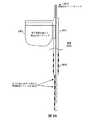
図31は発明の一層の実施の形態に従って対象の体に流体を配送する別の装置を示す。装置は、隔壁3101を備える流体リザーバ3103と、カテーテル3107を含む。装置は人間又は動物(対象)の皮膚の内面を流体で満たされた体内の非管器官につなげて、金属空洞針3109(図32に詳細に示す)にて終端する可撓性のポリマーカテーテル3107を通して特定の器官に局部的に流体又は薬液剤を注射することを可能にする。流体リザーバ3103と隔壁3101は外部ポンプ又は埋込ポンプによって運転されてもよい。装置は、リザーバ3103とカテーテル3107の間に配設される細菌ろ過器3105及び/又は流れ拘束器(絞り装置)を含んでもよい。関連する実施の形態によると、装置はまた、隔壁3101上に針を位置させるための、リザーバ3103の内スキン面上にドーナツ状(リング状)の金メッキされた磁石(図示省略)を含むことができる。そのような磁石をリザーバ3103を覆っているシリコーンに連続するシリコーン層内に封止することとしてもよい。さらに、カテーテル3107の内面と、出口針3109は、線維組織の成長を防止又は制限しバイオフィルムの形成を防止するために、疎水性又は親水性の絶縁保護コーティングでコーティングされてもよい。出口針3109はその先端又は側部に出口を持つことができる。そのような装置は人間か動物(対象)の内耳、ぼうこう、胃、又は腸管に接続されてもよい。対象の内耳に接続されるときは、針3109は後方鼓膜切除術又は乳突切除の際に部分的に挿入されてもよい。 FIG. 31 illustrates another apparatus for delivering fluid to a subject's body in accordance with a further embodiment of the invention. The device includes a
上で述べたように、リザーバ3103を金属製とし、それをシリコーンで覆うこととしてもよい。リザーバをまた円錐形に形成し、隔壁3101をその円錐のより大きい直径上に配設してもよい。対象の内耳に接続されると、そのような円錐形に形成されたリザーバは乳突切除部にうまくはめ込めるように適切な大きさのものであるべきであり、そのため、リザーバ3103の非隔壁側がカテーテル3107につなげられる。カテーテル3107は針3109の外面で終わる。図32に示すように、針3109は、骨を部分的に薄くした後で、岬角骨上又は内耳の半規管内に導入されるように設計されてもよい。針3109は骨に取り付くためのとげ付き外面と、固着(アンカー)装置3201を含んでもよい。針3109はまた、針の先から僅かの距離の位置に位置する円錐ストッパ3113を含んでもよい。 As described above, the
図33は、図31と32の実施の形態と共に使用されてもよい埋込み式アクセスポートを示す。アクセスポートは、圧縮されたシリコーンで作ることができる入力隔壁3301と、マイクロリザーバ3303と、ポート針3307を含む。シリコーン中に埋め込まれた金属リング3305によってポート針3307をアクセスポートに据えつけられてもよい。ポート針3307はシリコーンで部分的に覆われていてもよく、その先端又は側面に出口を持つことができる。ドリルで骨の覆いを部分的に除去した後に、ポート針3307を内耳の流体内に導入することとしてもよい。関連する実施の形態によると、ポート針3107は、入力隔壁3301を用いて後部鼓膜切開術において部分的に挿入され、乳突切除においてマイクロリザーバ3303に挿入されることもできる。 FIG. 33 illustrates an embedded access port that may be used with the embodiment of FIGS. The access port includes an
図34は、図31に関して説明した装置及び/又は図32に示されかつ説明された針につなぐことができる埋込み式アクセスポートを示す図である。 FIG. 34 illustrates the device described with respect to FIG. 31 and / or the implantable access port that can be coupled to the needle shown and described in FIG.
上で述べたように、ここで説明する発明とその実施の形態は内耳への応用に制限されるものではない。また、電気刺激のあるなしにかかわらずポンプと配送カテーテルを利用することが望ましい体の他のいかなる部位にもこの接続システムを使用することが可能である。例えば、そのような接続は頭蓋骨上又は頭蓋骨内において脳内のいくらかの位置へ流体を配送するための好ましい位置においてなされる。 As stated above, the invention and its embodiments described herein are not limited to application to the inner ear. It is also possible to use this connection system for any other part of the body where it is desirable to utilize a pump and delivery catheter with or without electrical stimulation. For example, such a connection is made at a preferred location for delivering fluid to some location within the brain on or within the skull.
発明をその特定の実施の形態に関して説明したが、別の変形例ができることが理解されるであろう。この出願は発明のいかなる変形例、用途、又は適合もカバーすることを意図し、本発明に開示されたものから出発して発明の当該技術において公知又は実施されているものに到達するようなものを含んでいる。 Although the invention has been described with respect to specific embodiments thereof, it will be understood that other variations are possible. This application is intended to cover any variations, uses, or adaptations of the invention, starting from what is disclosed in the present invention and reaching what is known or practiced in the art of the invention. Is included.
Claims (21)
Translated fromJapanese電極リード、
電極接触子と電極接触子の近くに1つ以上の流体出口を含む電極アレイ;
電極リード及び電極アレイに形成され、電極リード及び電極アレイを通して流体の搬送を可能にする流体搬送チャネルであり、流体出口に流体連通する流体搬送チャネル;及び
電極リードの流体搬送チャネルに隣接し取り付けられる埋込み可能なハウジングであり、電極接触子に送られる電流パルスを発生させる電子装置を含む埋込み可能なハウジング、
を含んでなる前記移植蝸牛刺激システム。A transplant cochlear stimulationsystem ,
Electrode leads,
An electrode array comprising an electrodecontact and one or more fluid outlets inthe vicinity of the electrode contact ;
A fluid transport channel formed in the electrode lead and the electrode array and enabling fluid transport through the electrode lead and electrode array and in fluid communication with the fluid outlet ; and
An implantable housing that is mounted adjacent to a fluid delivery channel of an electrode lead and includes an electronic device that generates a current pulse that is sent to the electrode contact;
The transplanted cochlear stimulationsystem comprising:
隔壁を有する埋込み可能なポートコネクタ、及び
前記隔壁に挿入する針を有する埋込み可能なスピアコネクタを、
含んでなる、
前記移植蝸牛刺激システム。The implantable cochlear stimulation system according to claim 1, further comprising a micro septum connector in fluid communication with a fluid delivery channel of an electrode lead, the micro septum connector comprising :
An implantable port connector having a septum, and an implantable spear connector having a needle inserted into the septum.
Comprising
Thetransplanted cochlear stimulation system .
前記埋込み可能なポートコネクタは、
前記針と流体連通する流体源、
前記隔壁に圧力をかける圧力リング、及び
前記針が前記隔壁に挿入されるときに前記針を案内する機構とを、
含んでなる、
前記移植蝸牛刺激システム。Thetransplant cochlear stimulation system according to claim2 ,
The implantable port connector is
A fluid source in fluid communication with the needle;
A pressure ring that applies pressure to the septum, and a mechanism that guides the needle when the needle is inserted into the septum.
Comprising
Thetransplanted cochlear stimulation system.
前記埋込み可能なポートコネクタと前記埋込み可能なスピアコネクタが直接接触することを防ぐ停止装置、及び
前記隔壁から前記針が離脱することを防ぐロック装置
をさらに含んでなる、
前記移植蝸牛刺激システム。Thetransplant cochlear stimulation system according to claim2 ,
A stop device that prevents direct contact between the implantable port connector and the implantable spear connector, and a lock device that prevents the needle from being detached from the septum.
Thetransplanted cochlear stimulation system.
前記埋込み可能なポートコネクタに流体連通するポートカテーテルをさらに含
んでなる、前記移植蝸牛刺激システム。Thetransplant cochlear stimulation system according to claim2 ,
The implantablecochlear stimulation system further comprising a port catheter in fluid communication with the implantable port connector.
ネクタは針と流体連通する流体源を含み、前記システムは前記流体源と前記ポ
ートカテーテルの間に配設された細菌ろ過器をさらに含んでなる、
前記移植蝸牛刺激システム。6. The implantablecochlear stimulation system according to claim5 ,wherein the implantable portco
The nectar includes a fluid source in fluid communication with the needle, and the system further comprises a bacterial filter disposed between the fluid source and the port catheter.
Thetransplanted cochlear stimulation system.
ネクタと前記ポートカテーテルの間に配設された細菌ろ過器をさらに含んでな
る、前記移植蝸牛刺激システム。6. Thetransplanted cochlear stimulation system according to claim5 , further comprising a bacterial filter disposed between the implantable port connector and the port catheter.
アカテーテルをさらに含んでなる前記移植蝸牛刺激システム。Thetransplanted cochlear stimulation system according to claim2 , further comprising a spear catheter in fluid communication with the needle.
埋込み可能な流体源、
前記流体源に流体連通する第1カテーテル、及び
前記電極リードの流体搬送チャネルと流体連通するマイクロ隔壁コネクタをさらに含んでなり、前記マイクロ隔壁コネクタは
前記第1カテーテルに連通し、かつ針を有する埋込み可能なスピアコネクタ、及び
前記針を挿入する隔壁を有する埋込み可能なポートコネクタを
含む、マイクロ隔壁コネクタ、
を含んでなる前記移植蝸牛刺激システム。The transplant cochlear stimulation system according to claim 1 ,
Implantable fluid source,
A first catheter in fluid communication with the fluid source; and
And further comprising a micro septum connector in fluid communication with the fluid delivery channel of the electrode lead, the micro septum connector communicating with the first catheter and having animplantable spear connector , and a septum for inserting the needle Amicro bulkhead connector , including an implantable port connector having
Thetransplanted cochlear stimulation system comprising:
ルをさらに含んでなる、請求項9に記載の移植蝸牛刺激システム。Theimplantable cochlear stimulation system of claim9 , further comprising a second catheter in fluid communication with the implantable port connector.
システム。Thetransplanted cochlear stimulation of claim9 , wherein the fluid source is a liquid pump.
system.
ステム。Thetransplanted cochlear stimulation system according to claim9 , wherein the fluid source is a reservoir.
Stem.
流体源に流体連通する第1カテーテルと、
マイクロ隔壁コネクタであり、
前記第1カテーテルに連通する埋込み可能なスピアコネクタを含み、前記埋込み可能なスピアコネクタは針を含み、及び
該針を挿入する隔壁を有する埋込み可能なポートコネクタを含んでなる、マイクロ隔壁コネクタ、及び
前記埋込み可能なポートコネクタに流体連通し、及び電極リードの流体搬送チャネルに流体連通する第2カテーテル
をさらに含んで成る、前記移植蝸牛刺激システム。The transplant cochlear stimulation system according to claim 1 ,
A first catheter in fluid communication with a fluid source;
Micro bulkhead connector ,
A micro septum connector comprising an implantablespear connector in communication with the first catheter, theimplantable spear connector comprising aneedle and an implantable port connector having a septum for inserting theneedle ; and The implantable cochlear stimulation system further comprising a second catheterin fluid communication with the implantable port connector and in fluidcommunication with a fluid delivery channel of an electrode lead .
流体源に流体連通する第1カテーテル、
電極リードの流体搬送チャネルに流体連通するマイクロ隔壁コネクタであって、
マイクロ隔壁コネクタは、
前記第1カテーテルに連通する埋込み可能なスピアコネクタを含み、前記埋込み可能なスピアコネクタは針を含み、及び
該針を挿入する隔壁を有する埋込み可能なポートコネクタを含んでなる、マイクロ隔壁コネクタ、及び
前記埋込み可能なポートコネクタを対象の内耳に取り付けるための固定装置を、
さらに含んでなる移植蝸牛刺激システム。Thetransplant cochlear stimulation system according to claim1 ,
A first catheter in fluid communication with a fluid source;
A micro septum connector in fluid communication with a fluid carrying channel of an electrode lead,
Micro bulkhead connector
A micro septum connector comprising an implantablespear connector in communication with the first catheter, theimplantable spear connector comprising aneedle , and an implantable port connector having a septum for inserting theneedle ; and A fixation device for attaching the implantable port connector to a target inner ear;
A transplant cochlear stimulation system further comprising:
ルをさらに含んでなる、請求項14に記載の移植蝸牛刺激システム。Theimplantable cochlear stimulation system according to claim14 , further comprising a second catheter in fluid communication with the implantable port connector.
載の移植蝸牛刺激システム。Thetransplant cochlear stimulation system according to claim14 , wherein the fixation device is attached to a cape angle bone of the subject.
第1隔壁を含む埋込み可能な流体リザーバと、
前記埋込み可能な流体リザーバに流体連通するカテーテルと、
前記カテーテルに流体連通する第1針とを、
さらに含んでなる前記移植蝸牛刺激システム。Thetransplant cochlear stimulation system according to claim1 ,
An implantable fluid reservoir including a first septum;
A catheter in fluid communication with the implantable fluid reservoir;
A first needle in fluid communication with the catheter;
Thetransplant cochlear stimulation system further comprising:
Applications Claiming Priority (5)
| Application Number | Priority Date | Filing Date | Title |
|---|---|---|---|
| US33645201P | 2001-10-24 | 2001-10-24 | |
| US39442702P | 2002-07-08 | 2002-07-08 | |
| US39460202P | 2002-07-09 | 2002-07-09 | |
| US41770402P | 2002-10-10 | 2002-10-10 | |
| PCT/IB2002/004731WO2003034960A1 (en) | 2001-10-24 | 2002-10-24 | Implantable fluid delivery apparatuses and implantable electrode |
Publications (2)
| Publication Number | Publication Date |
|---|---|
| JP2005506148A JP2005506148A (en) | 2005-03-03 |
| JP4398728B2true JP4398728B2 (en) | 2010-01-13 |
Family
ID=27502541
Family Applications (1)
| Application Number | Title | Priority Date | Filing Date |
|---|---|---|---|
| JP2003537531AExpired - LifetimeJP4398728B2 (en) | 2001-10-24 | 2002-10-24 | Implantable fluid delivery device and implantable electrode |
Country Status (6)
| Country | Link |
|---|---|
| US (6) | US7044942B2 (en) |
| EP (3) | EP2221030A1 (en) |
| JP (1) | JP4398728B2 (en) |
| AU (3) | AU2002363103B2 (en) |
| CA (1) | CA2460676C (en) |
| WO (1) | WO2003034960A1 (en) |
Families Citing this family (155)
| Publication number | Priority date | Publication date | Assignee | Title |
|---|---|---|---|---|
| US8177762B2 (en) | 1998-12-07 | 2012-05-15 | C. R. Bard, Inc. | Septum including at least one identifiable feature, access ports including same, and related methods |
| JP2001169067A (en)* | 1999-12-10 | 2001-06-22 | Ricoh Co Ltd | IMAGE PROCESSING DEVICE, IMAGE INFORMATION MANAGEMENT METHOD, AND COMPUTER-READABLE STORAGE MEDIUM STORING PROGRAM FOR CAUSING COMPUTER TO EXECUTE THE METHOD |
| AUPR148400A0 (en) | 2000-11-14 | 2000-12-07 | Cochlear Limited | Apparatus for delivery of pharmaceuticals to the cochlea |
| US9089450B2 (en)* | 2000-11-14 | 2015-07-28 | Cochlear Limited | Implantatable component having an accessible lumen and a drug release capsule for introduction into same |
| US7702394B2 (en) | 2001-05-01 | 2010-04-20 | Intrapace, Inc. | Responsive gastric stimulator |
| US20070088335A1 (en)* | 2001-10-24 | 2007-04-19 | Med-El Elektromedizinische Geraete Gmbh | Implantable neuro-stimulation electrode with fluid reservoir |
| JP4398728B2 (en)* | 2001-10-24 | 2010-01-13 | メド−エル・エレクトロメディツィニシェ・ゲラーテ・ゲーエムベーハー | Implantable fluid delivery device and implantable electrode |
| US20100030130A1 (en)* | 2001-11-09 | 2010-02-04 | Cochlear Limited | Pharmaceutical intervention for modulation of neural plasticity |
| AUPR879201A0 (en)* | 2001-11-09 | 2001-12-06 | Cochlear Limited | Subthreshold stimulation of a cochlea |
| AUPS081502A0 (en)* | 2002-02-28 | 2002-03-21 | Cochlear Limited | Connector for drug delivery system |
| US7009502B2 (en) | 2002-08-26 | 2006-03-07 | Automotive Technologies International, Inc. | Method for controlling output of a classification algorithm |
| US7319906B2 (en)* | 2002-09-19 | 2008-01-15 | Advanced Bionics Corporation | Cochlear implant electrode and method of making same |
| CA2498266A1 (en)* | 2002-09-19 | 2004-04-01 | Advanced Bionics Corporation | Cochlear implant electrode and method of making same |
| US7014636B2 (en)* | 2002-11-21 | 2006-03-21 | Alza Corporation | Osmotic delivery device having a two-way valve and a dynamically self-adjusting flow channel |
| US8515560B2 (en)* | 2002-11-29 | 2013-08-20 | Cochlear Limited | Medical implant drug delivery device |
| US7351246B2 (en)* | 2004-01-20 | 2008-04-01 | Epley John M | Minimally invasive, sustained, intra-tympanic drug delivery system |
| US7867194B2 (en) | 2004-01-29 | 2011-01-11 | The Charles Stark Draper Laboratory, Inc. | Drug delivery apparatus |
| WO2005072793A1 (en)* | 2004-01-29 | 2005-08-11 | The Charles Stark Draper Laboratory, Inc. | Implantable drug delivery apparatus |
| AU2005212341B2 (en)* | 2004-02-10 | 2011-11-24 | Synecor, Llc. | Intravascular delivery system for therapeutic agents |
| US7706873B2 (en)* | 2004-05-05 | 2010-04-27 | Mario Ammirati | System and method for controlled delivery of a therapeutic agent to a target location within an internal body tissue |
| US7658753B2 (en)* | 2004-08-03 | 2010-02-09 | K Spine, Inc. | Device and method for correcting a spinal deformity |
| US8934976B2 (en) | 2004-09-23 | 2015-01-13 | Intrapace, Inc. | Feedback systems and methods to enhance obstructive and other obesity treatments, optionally using multiple sensors |
| EP1846095A4 (en)* | 2005-01-20 | 2014-03-05 | Epley Medical Llc | Minimally invasive, sustained, intra-tympanic drug delivery system |
| CA2594963A1 (en)* | 2005-01-24 | 2006-07-27 | Neurosystec Corporation | Apparatus and method for delivering therapeutic and/or other agents to the inner ear and to other tissues |
| US11246913B2 (en) | 2005-02-03 | 2022-02-15 | Intarcia Therapeutics, Inc. | Suspension formulation comprising an insulinotropic peptide |
| US7947022B2 (en) | 2005-03-04 | 2011-05-24 | C. R. Bard, Inc. | Access port identification systems and methods |
| US8029482B2 (en) | 2005-03-04 | 2011-10-04 | C. R. Bard, Inc. | Systems and methods for radiographically identifying an access port |
| US9474888B2 (en) | 2005-03-04 | 2016-10-25 | C. R. Bard, Inc. | Implantable access port including a sandwiched radiopaque insert |
| JP5484674B2 (en) | 2005-03-04 | 2014-05-07 | シー・アール・バード・インコーポレーテッド | Access port and identification method |
| US20110077579A1 (en)* | 2005-03-24 | 2011-03-31 | Harrison William V | Cochlear implant with localized fluid transport |
| US8078275B2 (en)* | 2005-04-15 | 2011-12-13 | Functional Neuromodulation Inc. | Regulation of neurotrophins |
| EP1874393B1 (en) | 2005-04-27 | 2017-09-06 | C.R.Bard, Inc. | Infusion apparatuses |
| US10307581B2 (en) | 2005-04-27 | 2019-06-04 | C. R. Bard, Inc. | Reinforced septum for an implantable medical device |
| EP3884989B1 (en) | 2005-04-27 | 2022-07-13 | C. R. Bard, Inc. | Vascular access port |
| WO2006127123A2 (en)* | 2005-05-20 | 2006-11-30 | Medtronic, Inc. | Locking catheter connector and method |
| US7387624B2 (en)* | 2005-05-20 | 2008-06-17 | Medtronic, Inc. | Squeeze-actuated catheter connecter and method |
| US20060280655A1 (en)* | 2005-06-08 | 2006-12-14 | California Institute Of Technology | Intravascular diagnostic and therapeutic sampling device |
| US8805547B2 (en)* | 2005-06-30 | 2014-08-12 | Domestic Legacy Limited Partnership | Extra-cochlear implanted hearing aid device |
| WO2007030743A2 (en) | 2005-09-08 | 2007-03-15 | Massachusetts Eye & Ear Infirmary | Cochlear implants containing biological cells and uses thereof |
| US20100331913A1 (en)* | 2005-10-28 | 2010-12-30 | Mann Alfred E | Hybrid multi-function electrode array |
| DE102006009424A1 (en)* | 2006-02-24 | 2007-09-06 | Universität Rostock | Electrohydrodynamic micropump and its use |
| AR059786A1 (en)* | 2006-03-09 | 2008-04-30 | Med El Elektromed Geraete Gmbh | CONFIGURATION OF COCLEAR IMPLANT ELECTRODE TO ELECT PHARMACOS |
| US7650194B2 (en)* | 2006-03-22 | 2010-01-19 | Fritsch Michael H | Intracochlear nanotechnology and perfusion hearing aid device |
| US8267905B2 (en)* | 2006-05-01 | 2012-09-18 | Neurosystec Corporation | Apparatus and method for delivery of therapeutic and other types of agents |
| US7803148B2 (en) | 2006-06-09 | 2010-09-28 | Neurosystec Corporation | Flow-induced delivery from a drug mass |
| US7706888B2 (en)* | 2006-07-14 | 2010-04-27 | Med-El Elektromedizinische Geraete Gmbh | Bi-planar electrode with shunting gates |
| US7720542B2 (en)* | 2006-07-17 | 2010-05-18 | Med-El Elektromedizinische Geraete Gmbh | Remote sensing and actuation of fluid in cranial implants |
| CN101484102B (en)* | 2006-07-17 | 2011-02-23 | Med-El电气医疗器械有限公司 | Remote sensing and actuation of inner ear fluids |
| EP2056793A4 (en)* | 2006-07-31 | 2011-08-17 | Neurosystec Corp | Free base gacyclidine nanoparticles |
| EP3421031A1 (en) | 2006-08-09 | 2019-01-02 | Intarcia Therapeutics, Inc | Osmotic delivery systems and piston assemblies |
| US20080065002A1 (en)* | 2006-09-07 | 2008-03-13 | Neurosystec Corporation | Catheter for Localized Drug Delivery and/or Electrical Stimulation |
| US9265912B2 (en) | 2006-11-08 | 2016-02-23 | C. R. Bard, Inc. | Indicia informative of characteristics of insertable medical devices |
| US9642986B2 (en) | 2006-11-08 | 2017-05-09 | C. R. Bard, Inc. | Resource information key for an insertable medical device |
| WO2008094672A2 (en) | 2007-01-31 | 2008-08-07 | Charles Stark Draper Laboratory, Inc. | Membrane-based fluid control in microfluidic devices |
| US7844345B2 (en)* | 2007-02-08 | 2010-11-30 | Neuropace, Inc. | Drug eluting lead systems |
| US7813811B2 (en) | 2007-02-08 | 2010-10-12 | Neuropace, Inc. | Refillable reservoir lead systems |
| EP1972359B1 (en) | 2007-03-20 | 2015-01-28 | Cochlear Limited | Securing an implanted medical device in a patient |
| MX2009011123A (en) | 2007-04-23 | 2009-11-02 | Intarcia Therapeutics Inc | Suspension formulations of insulinotropic peptides and uses thereof. |
| WO2008150974A1 (en)* | 2007-06-01 | 2008-12-11 | Med-El Elektromedizinische Geraete Gmbh | Biodegradable flexible coating for implantable medical devices |
| ES2651269T3 (en) | 2007-06-20 | 2018-01-25 | Medical Components, Inc. | Venous reservoir with molded indications and / or radiopacas |
| WO2009012385A1 (en) | 2007-07-19 | 2009-01-22 | Medical Components, Inc. | Venous access port assembly with x-ray discernable indicia |
| US9610432B2 (en) | 2007-07-19 | 2017-04-04 | Innovative Medical Devices, Llc | Venous access port assembly with X-ray discernable indicia |
| US8133215B2 (en)* | 2007-08-13 | 2012-03-13 | Cochlear Limited | Independently-manufactured drug delivery module and corresponding receptacle in an implantable medical device |
| US8366652B2 (en) | 2007-08-17 | 2013-02-05 | The Invention Science Fund I, Llc | Systems, devices, and methods including infection-fighting and monitoring shunts |
| US8271101B2 (en) | 2007-08-29 | 2012-09-18 | Advanced Bionics | Modular drug delivery system for minimizing trauma during and after insertion of a cochlear lead |
| WO2009029866A2 (en) | 2007-08-29 | 2009-03-05 | Advanced Bionics, Llc | Minimizing trauma during and after insertion of a cochlear lead |
| US20130079749A1 (en)* | 2007-08-29 | 2013-03-28 | Advanced Bionics, Llc | Modular Drug Delivery System for Minimizing Trauma During and After Insertion of a Cochlear Lead |
| US9579496B2 (en) | 2007-11-07 | 2017-02-28 | C. R. Bard, Inc. | Radiopaque and septum-based indicators for a multi-lumen implantable port |
| WO2009092067A2 (en)* | 2008-01-18 | 2009-07-23 | Neurosystec Corporation | Valveless impedance pump drug delivery systems |
| WO2009102467A2 (en) | 2008-02-13 | 2009-08-20 | Intarcia Therapeutics, Inc. | Devices, formulations, and methods for delivery of multiple beneficial agents |
| US8209017B1 (en) | 2008-04-16 | 2012-06-26 | Boston Scientific Neuromodulation Corporation | Septum for covering a fastener assembly on a connector of an implantable electric stimulation system and methods of making and using |
| US8301260B2 (en)* | 2008-08-13 | 2012-10-30 | Daglow Terry D | Method of implanting a medical implant to treat hearing loss in a patient, devices for faciliting implantation of such devices, and medical implants for treating hearing loss |
| EP2344240A1 (en)* | 2008-08-21 | 2011-07-20 | Med-El Elektromedizinische Geräte GmbH | Multipath stimulation hearing systems |
| CA2739431C (en) | 2008-10-01 | 2016-12-06 | Sherwin Hua | System and method for wire-guided pedicle screw stabilization of spinal vertebrae |
| AU2009302494B2 (en)* | 2008-10-08 | 2013-03-07 | Med-El Elektromedizinische Geraete Gmbh | Cochlear tissue protection from electrode trauma |
| AU2009305745B9 (en)* | 2008-10-15 | 2013-07-18 | Med-El Elektromedizinische Geraete Gmbh | Inner ear drug delivery device and method |
| ES2906416T3 (en) | 2008-10-31 | 2022-04-18 | Bard Inc C R | Systems and methods to identify an access road |
| EP2379165B1 (en)* | 2008-11-10 | 2016-09-14 | MED-EL Elektromedizinische Geräte GmbH | Implantable and refillable drug delivery reservoir |
| CA2745453C (en) | 2008-11-10 | 2015-06-16 | Med-El Elektromedizinische Geraete Gmbh | Hydrogel-filled drug delivery reservoirs |
| US9795442B2 (en) | 2008-11-11 | 2017-10-24 | Shifamed Holdings, Llc | Ablation catheters |
| US11890443B2 (en) | 2008-11-13 | 2024-02-06 | C. R. Bard, Inc. | Implantable medical devices including septum-based indicators |
| US8932271B2 (en) | 2008-11-13 | 2015-01-13 | C. R. Bard, Inc. | Implantable medical devices including septum-based indicators |
| US20120041285A1 (en)* | 2008-12-04 | 2012-02-16 | Searete Llc, A Limited Liability Corporation Of The State Of Delaware | Systems, devices, and methods including implantable devices with anti-microbial properties |
| AU2010210541B2 (en)* | 2009-02-06 | 2012-10-18 | Med-El Elektromedizinische Geraete Gmbh | Implantable electrode with variable mechanical modulation wiring |
| AU2009202253A1 (en)* | 2009-03-24 | 2011-09-08 | Advanced Bionics Ag | Fully or partially implantable hearing system |
| US20110087076A1 (en)* | 2009-04-03 | 2011-04-14 | Intrapace, Inc. | Feedback systems and methods for communicating diagnostic and/or treatment signals to enhance obesity treatments |
| EP2451512A1 (en) | 2009-07-07 | 2012-05-16 | C.R. Bard Inc. | Extensible internal bolster for a medical device |
| NZ598686A (en) | 2009-09-28 | 2014-05-30 | Intarcia Therapeutics Inc | Rapid establishment and/or termination of substantial steady-state drug delivery |
| US20110093051A1 (en)* | 2009-10-21 | 2011-04-21 | Medtronic, Inc. | Assignment and manipulation of implantable leads in different anatomical regions with image background |
| ES2695907T3 (en) | 2009-11-17 | 2019-01-11 | Bard Inc C R | Overmolded access port that includes anchoring and identification features |
| KR20130004253A (en) | 2009-12-21 | 2013-01-09 | 셔윈 화 | Insertion of medical devices through non-orthogonal and orthogonal trajectories within the cranium and methods of using |
| US20110202120A1 (en)* | 2010-02-16 | 2011-08-18 | Med-El Elektromedizinische Geraete Gmbh | Electrode Design for Reduced Trauma Insertion |
| AU2011232335A1 (en)* | 2010-03-24 | 2012-10-11 | Shifamed Holdings, Llc | Intravascular tissue disruption |
| US8909348B2 (en) | 2010-03-30 | 2014-12-09 | Domestic Legacy Limited Partnership | Cochlear implant stabilization and positioning device |
| US9814885B2 (en) | 2010-04-27 | 2017-11-14 | Medtronic, Inc. | Stimulation electrode selection |
| AU2011252976A1 (en) | 2010-05-12 | 2012-11-08 | Shifamed Holdings, Llc | Low profile electrode assembly |
| US9655677B2 (en) | 2010-05-12 | 2017-05-23 | Shifamed Holdings, Llc | Ablation catheters including a balloon and electrodes |
| US8617097B2 (en) | 2010-05-24 | 2013-12-31 | Cochlear Limited | Drug-delivery accessory for an implantable medical device |
| WO2012022920A1 (en)* | 2010-08-19 | 2012-02-23 | INSERM (Institut National de la Santé et de la Recherche Médicale) | Device that is implantable in the temporal bone for delivering a material, and hearing aid provided with such a device |
| US9333331B2 (en)* | 2010-11-08 | 2016-05-10 | Cendres+Metaux Sa | Method for implanting an access port |
| USD676955S1 (en) | 2010-12-30 | 2013-02-26 | C. R. Bard, Inc. | Implantable access port |
| USD682416S1 (en) | 2010-12-30 | 2013-05-14 | C. R. Bard, Inc. | Implantable access port |
| CA2825757C (en) | 2011-02-02 | 2019-09-03 | The Charles Stark Draper Laboratory, Inc. | Drug delivery apparatus |
| US20120208755A1 (en) | 2011-02-16 | 2012-08-16 | Intarcia Therapeutics, Inc. | Compositions, Devices and Methods of Use Thereof for the Treatment of Cancers |
| EP2683332A2 (en)* | 2011-03-07 | 2014-01-15 | Heddon, Chris | Outer ear bone anchor |
| US20120245534A1 (en)* | 2011-03-25 | 2012-09-27 | Med-El Elektromedizinische Geraete Gmbh | Drug Delivery Electrode with Temporary Fill Tube |
| US8406890B2 (en) | 2011-04-14 | 2013-03-26 | Medtronic, Inc. | Implantable medical devices storing graphics processing data |
| US9011384B2 (en) | 2011-06-22 | 2015-04-21 | Chris Heddon | Outer ear bone anchor |
| CN106823131B (en) | 2011-09-30 | 2019-12-20 | 柯惠有限合伙公司 | Energy transfer device and method of use |
| CN104703650A (en)* | 2012-03-15 | 2015-06-10 | Med-El电气医疗器械有限公司 | Accessory device for inner ear drug delivery |
| WO2014011588A1 (en)* | 2012-07-13 | 2014-01-16 | Med-El Elektromedizinische Geraete Gmbh | Implantable fluid delivery system with floating mass transducer driven pump |
| KR101450859B1 (en) | 2012-10-10 | 2014-10-15 | 한국과학기술연구원 | Nerve electrode provided with a antiinflammatory drug and method for manufacturing the same |
| US20140121656A1 (en)* | 2012-10-26 | 2014-05-01 | Warsaw Orthopedic, Inc. | Nerve and soft tissue cutting device |
| US10349824B2 (en) | 2013-04-08 | 2019-07-16 | Apama Medical, Inc. | Tissue mapping and visualization systems |
| US10098694B2 (en) | 2013-04-08 | 2018-10-16 | Apama Medical, Inc. | Tissue ablation and monitoring thereof |
| KR20150140760A (en) | 2013-04-08 | 2015-12-16 | 아파마 메디칼, 인크. | Cardiac ablation catheters and methods of use thereof |
| US9480838B2 (en)* | 2013-10-15 | 2016-11-01 | Med-El Elektromedizinische Geraete Gmbh | Cochlear electrode with apical lateral wall section and basal modiolar hugging section |
| WO2015164340A1 (en)* | 2014-04-21 | 2015-10-29 | University Of South Florida | Magnetic resonant imaging safe stylus |
| WO2015179207A1 (en)* | 2014-05-19 | 2015-11-26 | Cain Frank J | Biomedical aural delivery systems and methods |
| US9616207B2 (en)* | 2014-06-26 | 2017-04-11 | Cochlear Limited | Treatment of the ear |
| WO2015200923A2 (en)* | 2014-06-27 | 2015-12-30 | The Trustees Of Columbia University In The City Of New York | Apparatus for perforation and aspiration of inner ear |
| US20160000548A1 (en)* | 2014-07-03 | 2016-01-07 | Elwha Llc | Devices, methods, and systems related to expandable implants |
| US9889085B1 (en) | 2014-09-30 | 2018-02-13 | Intarcia Therapeutics, Inc. | Therapeutic methods for the treatment of diabetes and related conditions for patients with high baseline HbA1c |
| TWI580279B (en)* | 2015-05-14 | 2017-04-21 | 陳光超 | Cochlea hearing aid fixed on ear drum |
| AU2016270984B2 (en) | 2015-06-03 | 2021-02-25 | Intarcia Therapeutics, Inc. | Implant placement and removal systems |
| WO2017011639A1 (en)* | 2015-07-15 | 2017-01-19 | Med-El Elektromedizinische Geraete Gmbh | Electrode lead that avoids electrode array migration from the cochlea |
| EP4302713A3 (en) | 2015-11-16 | 2024-03-13 | Boston Scientific Scimed, Inc. | Energy delivery devices |
| JP7077237B2 (en) | 2016-05-16 | 2022-05-30 | インターシア セラピューティクス,インコーポレイティド | Glucagon Receptor Selective Polypeptides and Their Usage |
| US11213430B2 (en) | 2016-05-26 | 2022-01-04 | Cochlear Limited | Inner ear plug |
| USD840030S1 (en) | 2016-06-02 | 2019-02-05 | Intarcia Therapeutics, Inc. | Implant placement guide |
| USD860451S1 (en) | 2016-06-02 | 2019-09-17 | Intarcia Therapeutics, Inc. | Implant removal tool |
| MX2019008006A (en) | 2017-01-03 | 2019-08-29 | Intarcia Therapeutics Inc | METHODS INCLUDING THE CONTINUOUS ADMINISTRATION OF A GLP-1 RECEPTOR AGONIST AND THE CO-ADMINISTRATION OF A DRUG. |
| EP3684311B1 (en)* | 2017-09-22 | 2023-10-25 | Cochlear Limited | Trans middle ear-inner ear fluid flow implementations |
| WO2019058333A2 (en) | 2017-09-22 | 2019-03-28 | Cochlear Limited | Bioactive agent distribution |
| EP3694579A4 (en)* | 2017-10-12 | 2021-07-07 | Cochlear Limited | Clinical-based automated delivery of treatment substances to the inner ear |
| US11524154B2 (en) | 2017-11-10 | 2022-12-13 | Med-El Elektromedizinische Geraete Gmbh | Navigatable implantable electrode and collapsing lubricant reservoir |
| CN111542288B (en)* | 2018-02-02 | 2023-08-08 | 塔斯克医药股份有限公司 | Systems, devices and methods for delivering and delivering therapeutic substances to the middle ear |
| KR102198944B1 (en)* | 2018-03-16 | 2021-01-05 | 의료법인 성광의료재단 | Intratympanic drug delivery device and intratympanic drug delivery method using the same |
| EP3781102B1 (en) | 2018-04-19 | 2025-09-24 | Spiral Therapeutics, Inc. | Inner ear drug delivery devices and methods of use |
| USD933219S1 (en) | 2018-07-13 | 2021-10-12 | Intarcia Therapeutics, Inc. | Implant removal tool and assembly |
| WO2020039402A1 (en) | 2018-08-24 | 2020-02-27 | Cochlear Limited | Mass transport inside mammals |
| WO2020104918A1 (en) | 2018-11-20 | 2020-05-28 | Cochlear Limited | Selectable drug delivery rate device |
| US11160580B2 (en) | 2019-04-24 | 2021-11-02 | Spine23 Inc. | Systems and methods for pedicle screw stabilization of spinal vertebrae |
| US11730884B2 (en) | 2019-09-05 | 2023-08-22 | Forcast Orthopedics Inc. | Implantable externally driven fluid delivery system |
| US11890438B1 (en)* | 2019-09-12 | 2024-02-06 | Cochlear Limited | Therapeutic substance delivery |
| CN110801574A (en)* | 2019-11-12 | 2020-02-18 | 江苏诺尔贝斯医疗科技有限公司 | Medical connector |
| EP4065016A1 (en) | 2019-11-27 | 2022-10-05 | Spine23 Inc. | Systems, devices and methods for treating a lateral curvature of a spine |
| AU2021209675A1 (en)* | 2020-01-24 | 2022-08-25 | Spiral Therapeutics Inc. | Visualization devices, systems, and methods for otology and other uses |
| WO2022147085A1 (en)* | 2020-12-31 | 2022-07-07 | The Johns Hopkins University | Devices and method for the conveyance of fluidic materials |
| WO2022241140A1 (en) | 2021-05-12 | 2022-11-17 | Spine23 Inc. | Systems and methods for pedicle screw stabilization of spinal vertebrae |
| MX2023015148A (en)* | 2021-06-30 | 2024-04-01 | Davol Inc | Methods and implantable prosthesis for reconstruction and/or augmentation of an anatomical shape. |
| EP4463102A1 (en)* | 2022-01-11 | 2024-11-20 | Cochlear Limited | Inner ear access shaped devices and methods |
| US20250229052A1 (en)* | 2022-04-25 | 2025-07-17 | Evanesce Medical, Inc. | Multimodal pain management systems and methods |
| WO2024038420A1 (en)* | 2022-08-19 | 2024-02-22 | Cochlear Limited | Substance delivery inside mammals |
| WO2024261557A1 (en)* | 2023-06-21 | 2024-12-26 | Cochlear Limited | Implant electrodes with electrolyte-filled region bounded by a barrier |
Family Cites Families (88)
| Publication number | Priority date | Publication date | Assignee | Title |
|---|---|---|---|---|
| US419677A (en)* | 1890-01-21 | Protecting-plate for grip-cars | ||
| US3277893A (en)* | 1964-01-31 | 1966-10-11 | Becton Dickinson Co | Hypodermic projectile with barb in the cannula bevel |
| US4207554A (en) | 1972-08-04 | 1980-06-10 | Med-El Inc. | Method and apparatus for automated classification and analysis of cells |
| US4125828A (en) | 1972-08-04 | 1978-11-14 | Med-El Inc. | Method and apparatus for automated classification and analysis of cells |
| US4053952A (en)* | 1975-10-10 | 1977-10-18 | The United States Of America As Represented By The Secretary Of The Department Of Health, Education And Welfare | Magnetic fluid actuated control valve, relief valve and pump |
| US4573994A (en)* | 1979-04-27 | 1986-03-04 | The Johns Hopkins University | Refillable medication infusion apparatus |
| US4400590A (en)* | 1980-12-22 | 1983-08-23 | The Regents Of The University Of California | Apparatus for multichannel cochlear implant hearing aid system |
| US4419995A (en)* | 1981-09-18 | 1983-12-13 | Hochmair Ingeborg | Single channel auditory stimulation system |
| US4588394A (en)* | 1984-03-16 | 1986-05-13 | Pudenz-Schulte Medical Research Corp. | Infusion reservoir and pump system |
| GB8618253D0 (en)* | 1986-07-25 | 1986-09-03 | Wallace Ltd H G | Intermittent administration of therapeutic substance |
| EP0309092B1 (en)* | 1987-08-25 | 1992-12-09 | Infusaid, Inc. | Implantable device |
| FR2629710B1 (en)* | 1988-04-08 | 1997-10-24 | Mxm | ELECTRODE HOLDER DEVICES IMPLANTABLE IN THE COCHLEE FOR ELECTRICALLY STIMULATING THE HEARING NERVE |
| DE3821970C1 (en)* | 1988-06-29 | 1989-12-14 | Ernst-Ludwig Von Dr. 8137 Berg De Wallenberg-Pachaly | |
| US5458631A (en)* | 1989-01-06 | 1995-10-17 | Xavier; Ravi | Implantable catheter with electrical pulse nerve stimulators and drug delivery system |
| US5119832A (en)* | 1989-07-11 | 1992-06-09 | Ravi Xavier | Epidural catheter with nerve stimulators |
| EP0412191B1 (en) | 1989-08-09 | 1993-02-03 | Siemens Aktiengesellschaft | Implantable infusion device |
| US5356381A (en)* | 1990-03-01 | 1994-10-18 | Ensminger William D | Implantable access devices |
| US5087243A (en)* | 1990-06-18 | 1992-02-11 | Boaz Avitall | Myocardial iontophoresis |
| US5421818A (en)* | 1993-10-18 | 1995-06-06 | Inner Ear Medical Delivery Systems, Inc. | Multi-functional inner ear treatment and diagnostic system |
| US5928229A (en)* | 1993-11-08 | 1999-07-27 | Rita Medical Systems, Inc. | Tumor ablation apparatus |
| US6129685A (en)* | 1994-02-09 | 2000-10-10 | The University Of Iowa Research Foundation | Stereotactic hypothalamic obesity probe |
| US5697975A (en)* | 1994-02-09 | 1997-12-16 | The University Of Iowa Research Foundation | Human cerebral cortex neural prosthetic for tinnitus |
| US5843093A (en)* | 1994-02-09 | 1998-12-01 | University Of Iowa Research Foundation | Stereotactic electrode assembly |
| US5607407A (en)* | 1994-05-09 | 1997-03-04 | Tolkoff; Marc J. | Catheter assembly |
| US5509888A (en)* | 1994-07-26 | 1996-04-23 | Conceptek Corporation | Controller valve device and method |
| DE69625805T2 (en)* | 1995-03-30 | 2003-11-13 | Cochlear Ltd., Lane Cove | ELECTRODE ARRANGEMENTS FOR COCHLEAR IMPLANT AND POSITIONING SYSTEM |
| WO1996033761A1 (en)* | 1995-04-28 | 1996-10-31 | Medtronic, Inc. | Intraparenchymal infusion catheter system |
| US5800500A (en)* | 1995-08-18 | 1998-09-01 | Pi Medical Corporation | Cochlear implant with shape memory material and method for implanting the same |
| WO1997010784A1 (en)* | 1995-09-20 | 1997-03-27 | Cochlear Limited | Bioresorbable polymer use in cochlear and other implants |
| ES2247624T3 (en) | 1996-02-26 | 2006-03-01 | Med-El Elektromedizinische Gerate Gmbh | STRUCTURE OF AN IMPLANTED AUDITIVE PROTESIS. |
| WO1997033647A1 (en) | 1996-03-13 | 1997-09-18 | Med-El Elektromedizinische Geräte GmbH | Device and method for implants in ossified cochleas |
| US5697951A (en)* | 1996-04-25 | 1997-12-16 | Medtronic, Inc. | Implantable stimulation and drug infusion techniques |
| WO1997047065A1 (en) | 1996-06-04 | 1997-12-11 | Murphy, Timothy, M. | A device for transferring electromagnetic energy between primary and secondary coils |
| ES2214627T3 (en)* | 1996-06-20 | 2004-09-16 | Advanced Bionics Corporation | SELF-ADJUSTABLE COCLEAR IMPLANT SYSTEM. |
| US6156728A (en)* | 1996-11-01 | 2000-12-05 | Genentech, Inc. | Treatment of inner ear hair cells |
| DE69833426T2 (en) | 1997-03-10 | 2006-08-17 | Med-El Elektromedizinische Geräte GmbH | DEVICE AND METHOD FOR PERIMODIOLAR COCHLEA IMPLANT WITH RETRO POSITIONING |
| DE69723225D1 (en)* | 1997-04-01 | 2003-08-07 | St Microelectronics Srl | Arrangement for testing a gate oxide |
| AU750976B2 (en) | 1997-05-01 | 2002-08-01 | Med-El Elektromedizinische Gerate Ges.M.B.H. | Apparatus and method for a low power digital filter bank |
| US6119044A (en)* | 1997-06-02 | 2000-09-12 | Advanced Bionics Corporation | Cochlear electrode array with positioning stylet |
| US6129753A (en)* | 1998-03-27 | 2000-10-10 | Advanced Bionics Corporation | Cochlear electrode array with electrode contacts on medial side |
| US6045528A (en)* | 1997-06-13 | 2000-04-04 | Intraear, Inc. | Inner ear fluid transfer and diagnostic system |
| US5997524A (en)* | 1997-07-18 | 1999-12-07 | Vasca, Inc. | Catheter assembly for percutaneous access to subcutaneous port |
| US6125302A (en)* | 1997-09-02 | 2000-09-26 | Advanced Bionics Corporation | Precurved modiolar-hugging cochlear electrode |
| USD419677S (en) | 1997-11-04 | 2000-01-25 | Med-El Elektromedizinische Gerate Ges.M.B.H. | Speech processor for use with a cochlear implant |
| US6093144A (en) | 1997-12-16 | 2000-07-25 | Symphonix Devices, Inc. | Implantable microphone having improved sensitivity and frequency response |
| US6231604B1 (en) | 1998-02-26 | 2001-05-15 | Med-El Elektromedizinische Gerate Ges.M.B.H | Apparatus and method for combined acoustic mechanical and electrical auditory stimulation |
| US6296630B1 (en)* | 1998-04-08 | 2001-10-02 | Biocardia, Inc. | Device and method to slow or stop the heart temporarily |
| US6348070B1 (en) | 1998-04-17 | 2002-02-19 | Med-El Elektromedizinische Gerate Ges.M.B.H | Magnetic-interference-free surgical prostheses |
| US6361494B1 (en) | 1998-05-18 | 2002-03-26 | Med-El. Elektromedizinische Gerate Ges.M.B.H. | Electrode and method for measuring muscle activity in the pharyngeal airways |
| US6266568B1 (en)* | 1998-06-02 | 2001-07-24 | Advanced Bionics Corporation | Inflatable cochlear electrode array and method of making same |
| DE19829637C2 (en)* | 1998-07-02 | 2000-10-19 | Implex Hear Tech Ag | Medical implant |
| US6440102B1 (en)* | 1998-07-23 | 2002-08-27 | Durect Corporation | Fluid transfer and diagnostic system for treating the inner ear |
| FR2781378B1 (en)* | 1998-07-23 | 2001-02-16 | Stephane Chanut | PROTECTED AND EASILY EXTRACTED NEEDLE DEVICE |
| US6309410B1 (en)* | 1998-08-26 | 2001-10-30 | Advanced Bionics Corporation | Cochlear electrode with drug delivery channel and method of making same |
| US6195586B1 (en)* | 1998-08-26 | 2001-02-27 | Advanced Bionics Corporation | Space-filling cochlear electrode |
| US6862805B1 (en)* | 1998-08-26 | 2005-03-08 | Advanced Bionics Corporation | Method of making a cochlear electrode array having current-focusing and tissue-treating features |
| US6968238B1 (en)* | 1998-08-26 | 2005-11-22 | Kuzma Janusz A | Method for inserting cochlear electrode and insertion tool for use therewith |
| US6397110B1 (en)* | 1998-08-26 | 2002-05-28 | Advanced Bionics Corporation | Cochlear electrode system including detachable flexible positioner |
| DE19853299C2 (en)* | 1998-11-19 | 2003-04-03 | Thomas Lenarz | Catheter for the application of medication in fluid spaces of the human inner ear |
| EP1090532A2 (en) | 1999-01-28 | 2001-04-11 | Cochlear Limited | Cochlea-implantable auditive prosthesis |
| US6535153B1 (en) | 1999-02-04 | 2003-03-18 | Med-El Electromedizinische Gerate Ges.M.B.H. | Adaptive sigma-delta modulation with one-bit quantization |
| WO2000069513A1 (en)* | 1999-05-14 | 2000-11-23 | Advanced Bionics Corporation | Electrode array for hybrid cochlear stimulator |
| US6259951B1 (en)* | 1999-05-14 | 2001-07-10 | Advanced Bionics Corporation | Implantable cochlear stimulator system incorporating combination electrode/transducer |
| EP2291005B1 (en) | 1999-07-21 | 2016-09-07 | MED-EL Elektromedizinische Geräte GmbH | Multichannel cochlea implant having neural telemetry reaction |
| US6374143B1 (en)* | 1999-08-18 | 2002-04-16 | Epic Biosonics, Inc. | Modiolar hugging electrode array |
| EP1207938B1 (en) | 1999-08-26 | 2007-10-24 | Med-El Elektromedizinische Geräte GmbH | Electrical nerve stimulation based on channel specific sampling sequences |
| US6363286B1 (en)* | 1999-09-24 | 2002-03-26 | Cardiac Pacemakers, Inc. | High impedance electrode assembly |
| US6358281B1 (en)* | 1999-11-29 | 2002-03-19 | Epic Biosonics Inc. | Totally implantable cochlear prosthesis |
| CA2395315C (en) | 2000-01-31 | 2008-08-05 | Med-El Elektromedizinische Gerate Gmbh | Cochlear implant system partially insertable in the external ear |
| DE10018334C1 (en)* | 2000-04-13 | 2002-02-28 | Implex Hear Tech Ag | At least partially implantable system for the rehabilitation of a hearing impairment |
| DE10018360C2 (en)* | 2000-04-13 | 2002-10-10 | Cochlear Ltd | At least partially implantable system for the rehabilitation of a hearing impairment |
| US6628991B2 (en)* | 2000-04-28 | 2003-09-30 | Advanced Bionics Corporation | Minimally-invasive access into the cochlea for electrode insertion and fluid delivery |
| AUPR148400A0 (en)* | 2000-11-14 | 2000-12-07 | Cochlear Limited | Apparatus for delivery of pharmaceuticals to the cochlea |
| US7050858B1 (en)* | 2001-04-06 | 2006-05-23 | Advanced Bionics Corporation | Insertion tool for placement of electrode system inside the cochlear lumen |
| US20040172005A1 (en)* | 2001-06-18 | 2004-09-02 | Arenberg Michael H. | Device and method for delivering microdoses of agent to the ear |
| JP4398728B2 (en) | 2001-10-24 | 2010-01-13 | メド−エル・エレクトロメディツィニシェ・ゲラーテ・ゲーエムベーハー | Implantable fluid delivery device and implantable electrode |
| EP1488525B1 (en) | 2002-03-28 | 2010-08-18 | Med-El Elektromedizinische Geräte GmbH | A system and method for adaptive sigma-delta modulation |
| EP1490148A2 (en) | 2002-04-01 | 2004-12-29 | Med-El Elektromedizinische Geräte GmbH | Reducing effect of magnetic and electromagnetic fields on an implants magnet and/or electronic |
| US20040012798A1 (en)* | 2002-07-19 | 2004-01-22 | Jeran Paul L. | Media handling device having media optimization |
| EP1536852B1 (en) | 2002-09-10 | 2016-11-16 | MED-EL Elektromedizinische Geräte GmbH | Implantable medical device with multiple transducers |
| CA2498266A1 (en) | 2002-09-19 | 2004-04-01 | Advanced Bionics Corporation | Cochlear implant electrode and method of making same |
| US7319906B2 (en)* | 2002-09-19 | 2008-01-15 | Advanced Bionics Corporation | Cochlear implant electrode and method of making same |
| US8021359B2 (en)* | 2003-02-13 | 2011-09-20 | Coaptus Medical Corporation | Transseptal closure of a patent foramen ovale and other cardiac defects |
| US6954913B2 (en)* | 2003-04-03 | 2005-10-11 | Sun Microsystems Inc. | System and method for in-situ signal delay measurement for a microprocessor |
| CA2594963A1 (en)* | 2005-01-24 | 2006-07-27 | Neurosystec Corporation | Apparatus and method for delivering therapeutic and/or other agents to the inner ear and to other tissues |
| JP4328764B2 (en)* | 2005-07-14 | 2009-09-09 | ジーイー・メディカル・システムズ・グローバル・テクノロジー・カンパニー・エルエルシー | Imaging device and transfer board moving device |
| US7555352B2 (en)* | 2005-11-08 | 2009-06-30 | Cochlear Limited | Implantable carrier member having a non-communicative lumen |
| US8444609B2 (en) | 2006-04-28 | 2013-05-21 | Medtronic, Inc. | Implantable therapeutic substance delivery system with catheter access port block and method of use |
- 2002
- 2002-10-24JPJP2003537531Apatent/JP4398728B2/ennot_activeExpired - Lifetime
- 2002-10-24AUAU2002363103Apatent/AU2002363103B2/ennot_activeExpired
- 2002-10-24EPEP10075175Apatent/EP2221030A1/ennot_activeWithdrawn
- 2002-10-24EPEP10075230.2Apatent/EP2226043B1/ennot_activeExpired - Lifetime
- 2002-10-24EPEP02801986.7Apatent/EP1441679B8/ennot_activeExpired - Lifetime
- 2002-10-24CACA2460676Apatent/CA2460676C/ennot_activeExpired - Lifetime
- 2002-10-24WOPCT/IB2002/004731patent/WO2003034960A1/enactiveApplication Filing
- 2002-10-24USUS10/281,066patent/US7044942B2/ennot_activeExpired - Lifetime
- 2006
- 2006-03-13USUS11/374,505patent/US7815615B2/ennot_activeExpired - Fee Related
- 2009
- 2009-01-16AUAU2009200181Apatent/AU2009200181B2/ennot_activeExpired
- 2010
- 2010-05-31AUAU2010202239Apatent/AU2010202239B2/ennot_activeExpired
- 2010-10-18USUS12/906,564patent/US20110034857A1/ennot_activeAbandoned
- 2014
- 2014-10-06USUS14/507,435patent/US9498608B2/ennot_activeExpired - Fee Related
- 2016
- 2016-04-14USUS15/098,399patent/US9550051B2/ennot_activeExpired - Fee Related
- 2016-10-14USUS15/293,797patent/US10272232B2/ennot_activeExpired - Lifetime
Also Published As
| Publication number | Publication date |
|---|---|
| AU2009200181B2 (en) | 2010-03-04 |
| AU2009200181A1 (en) | 2009-02-12 |
| AU2002363103B2 (en) | 2008-10-16 |
| US20030097121A1 (en) | 2003-05-22 |
| EP1441679A1 (en) | 2004-08-04 |
| CA2460676A1 (en) | 2003-05-01 |
| US20160220797A1 (en) | 2016-08-04 |
| US20110034857A1 (en) | 2011-02-10 |
| US10272232B2 (en) | 2019-04-30 |
| US7815615B2 (en) | 2010-10-19 |
| EP2226043A1 (en) | 2010-09-08 |
| US9550051B2 (en) | 2017-01-24 |
| EP2221030A1 (en) | 2010-08-25 |
| AU2010202239B2 (en) | 2013-01-24 |
| WO2003034960A1 (en) | 2003-05-01 |
| AU2010202239A1 (en) | 2010-06-24 |
| US9498608B2 (en) | 2016-11-22 |
| EP1441679B8 (en) | 2018-05-30 |
| EP1441679B1 (en) | 2018-04-04 |
| US20150025509A1 (en) | 2015-01-22 |
| US20060184143A1 (en) | 2006-08-17 |
| CA2460676C (en) | 2010-03-23 |
| US20170028182A1 (en) | 2017-02-02 |
| JP2005506148A (en) | 2005-03-03 |
| US7044942B2 (en) | 2006-05-16 |
| EP2226043B1 (en) | 2014-12-31 |
Similar Documents
| Publication | Publication Date | Title |
|---|---|---|
| JP4398728B2 (en) | Implantable fluid delivery device and implantable electrode | |
| KR101118349B1 (en) | Implantable neuro-stimulation electrode with fluid reservoir | |
| AU2002363103A1 (en) | Implantable fluid delivery apparatuses and implantable electrode | |
| US9089450B2 (en) | Implantatable component having an accessible lumen and a drug release capsule for introduction into same | |
| US11213430B2 (en) | Inner ear plug | |
| EP2047884B1 (en) | Implantable component having an accessible lumen and a drug delivery capsule for introduction into same | |
| CN112469466A (en) | Mass transport in mammals |
Legal Events
| Date | Code | Title | Description |
|---|---|---|---|
| A621 | Written request for application examination | Free format text:JAPANESE INTERMEDIATE CODE: A621 Effective date:20050721 | |
| A131 | Notification of reasons for refusal | Free format text:JAPANESE INTERMEDIATE CODE: A131 Effective date:20080909 | |
| A601 | Written request for extension of time | Free format text:JAPANESE INTERMEDIATE CODE: A601 Effective date:20081205 | |
| A602 | Written permission of extension of time | Free format text:JAPANESE INTERMEDIATE CODE: A602 Effective date:20081212 | |
| A601 | Written request for extension of time | Free format text:JAPANESE INTERMEDIATE CODE: A601 Effective date:20090108 | |
| A602 | Written permission of extension of time | Free format text:JAPANESE INTERMEDIATE CODE: A602 Effective date:20090116 | |
| A601 | Written request for extension of time | Free format text:JAPANESE INTERMEDIATE CODE: A601 Effective date:20090206 | |
| A602 | Written permission of extension of time | Free format text:JAPANESE INTERMEDIATE CODE: A602 Effective date:20090216 | |
| A521 | Request for written amendment filed | Free format text:JAPANESE INTERMEDIATE CODE: A523 Effective date:20090227 | |
| TRDD | Decision of grant or rejection written | ||
| A01 | Written decision to grant a patent or to grant a registration (utility model) | Free format text:JAPANESE INTERMEDIATE CODE: A01 Effective date:20090929 | |
| A01 | Written decision to grant a patent or to grant a registration (utility model) | Free format text:JAPANESE INTERMEDIATE CODE: A01 | |
| A61 | First payment of annual fees (during grant procedure) | Free format text:JAPANESE INTERMEDIATE CODE: A61 Effective date:20091023 | |
| FPAY | Renewal fee payment (event date is renewal date of database) | Free format text:PAYMENT UNTIL: 20121030 Year of fee payment:3 | |
| R150 | Certificate of patent or registration of utility model | Ref document number:4398728 Country of ref document:JP Free format text:JAPANESE INTERMEDIATE CODE: R150 Free format text:JAPANESE INTERMEDIATE CODE: R150 | |
| FPAY | Renewal fee payment (event date is renewal date of database) | Free format text:PAYMENT UNTIL: 20121030 Year of fee payment:3 | |
| FPAY | Renewal fee payment (event date is renewal date of database) | Free format text:PAYMENT UNTIL: 20131030 Year of fee payment:4 | |
| R250 | Receipt of annual fees | Free format text:JAPANESE INTERMEDIATE CODE: R250 | |
| R250 | Receipt of annual fees | Free format text:JAPANESE INTERMEDIATE CODE: R250 | |
| R250 | Receipt of annual fees | Free format text:JAPANESE INTERMEDIATE CODE: R250 | |
| R250 | Receipt of annual fees | Free format text:JAPANESE INTERMEDIATE CODE: R250 | |
| R250 | Receipt of annual fees | Free format text:JAPANESE INTERMEDIATE CODE: R250 | |
| R250 | Receipt of annual fees | Free format text:JAPANESE INTERMEDIATE CODE: R250 | |
| R250 | Receipt of annual fees | Free format text:JAPANESE INTERMEDIATE CODE: R250 | |
| R250 | Receipt of annual fees | Free format text:JAPANESE INTERMEDIATE CODE: R250 | |
| R250 | Receipt of annual fees | Free format text:JAPANESE INTERMEDIATE CODE: R250 | |
| R250 | Receipt of annual fees | Free format text:JAPANESE INTERMEDIATE CODE: R250 | |
| EXPY | Cancellation because of completion of term |