JP4398723B2 - Large-capacity bolus device - Google Patents
Large-capacity bolus deviceDownload PDFInfo
- Publication number
- JP4398723B2 JP4398723B2JP2003501530AJP2003501530AJP4398723B2JP 4398723 B2JP4398723 B2JP 4398723B2JP 2003501530 AJP2003501530 AJP 2003501530AJP 2003501530 AJP2003501530 AJP 2003501530AJP 4398723 B2JP4398723 B2JP 4398723B2
- Authority
- JP
- Japan
- Prior art keywords
- fluid
- bolus
- patient
- flow
- reservoir
- Prior art date
- Legal status (The legal status is an assumption and is not a legal conclusion. Google has not performed a legal analysis and makes no representation as to the accuracy of the status listed.)
- Expired - Lifetime
Links
- 239000012530fluidSubstances0.000claimsabstractdescription136
- 238000004891communicationMethods0.000claimsdescription4
- 238000000034methodMethods0.000abstractdescription15
- 230000000153supplemental effectEffects0.000abstractdescription5
- 230000000994depressogenic effectEffects0.000abstractdescription3
- 230000006837decompressionEffects0.000abstractdescription2
- 238000001802infusionMethods0.000abstractdescription2
- 239000008280bloodSubstances0.000abstract2
- 210000004369bloodAnatomy0.000abstract2
- 230000004913activationEffects0.000abstract1
- 238000013270controlled releaseMethods0.000abstract1
- 201000007902Primary cutaneous amyloidosisDiseases0.000description6
- 238000007906compressionMethods0.000description6
- 230000006835compressionEffects0.000description6
- 208000014670posterior cortical atrophyDiseases0.000description6
- 238000000513principal component analysisMethods0.000description6
- 238000010586diagramMethods0.000description4
- 238000003825pressingMethods0.000description4
- 229940035676analgesicsDrugs0.000description3
- 239000000730antalgic agentSubstances0.000description3
- 239000003242anti bacterial agentSubstances0.000description3
- 229940088710antibiotic agentDrugs0.000description3
- 229920001971elastomerPolymers0.000description3
- 239000000806elastomerSubstances0.000description3
- 239000003589local anesthetic agentSubstances0.000description3
- 210000005036nerveAnatomy0.000description3
- 239000002245particleSubstances0.000description3
- 229920003051synthetic elastomerPolymers0.000description3
- 230000001960triggered effectEffects0.000description3
- 244000043261Hevea brasiliensisSpecies0.000description2
- RRHGJUQNOFWUDK-UHFFFAOYSA-NIsopreneChemical compoundCC(=C)C=CRRHGJUQNOFWUDK-UHFFFAOYSA-N0.000description2
- 230000009286beneficial effectEffects0.000description2
- 230000017531blood circulationEffects0.000description2
- 239000000356contaminantSubstances0.000description2
- 230000000694effectsEffects0.000description2
- 239000013013elastic materialSubstances0.000description2
- NOESYZHRGYRDHS-UHFFFAOYSA-NinsulinChemical compoundN1C(=O)C(NC(=O)C(CCC(N)=O)NC(=O)C(CCC(O)=O)NC(=O)C(C(C)C)NC(=O)C(NC(=O)CN)C(C)CC)CSSCC(C(NC(CO)C(=O)NC(CC(C)C)C(=O)NC(CC=2C=CC(O)=CC=2)C(=O)NC(CCC(N)=O)C(=O)NC(CC(C)C)C(=O)NC(CCC(O)=O)C(=O)NC(CC(N)=O)C(=O)NC(CC=2C=CC(O)=CC=2)C(=O)NC(CSSCC(NC(=O)C(C(C)C)NC(=O)C(CC(C)C)NC(=O)C(CC=2C=CC(O)=CC=2)NC(=O)C(CC(C)C)NC(=O)C(C)NC(=O)C(CCC(O)=O)NC(=O)C(C(C)C)NC(=O)C(CC(C)C)NC(=O)C(CC=2NC=NC=2)NC(=O)C(CO)NC(=O)CNC2=O)C(=O)NCC(=O)NC(CCC(O)=O)C(=O)NC(CCCNC(N)=N)C(=O)NCC(=O)NC(CC=3C=CC=CC=3)C(=O)NC(CC=3C=CC=CC=3)C(=O)NC(CC=3C=CC(O)=CC=3)C(=O)NC(C(C)O)C(=O)N3C(CCC3)C(=O)NC(CCCCN)C(=O)NC(C)C(O)=O)C(=O)NC(CC(N)=O)C(O)=O)=O)NC(=O)C(C(C)CC)NC(=O)C(CO)NC(=O)C(C(C)O)NC(=O)C1CSSCC2NC(=O)C(CC(C)C)NC(=O)C(NC(=O)C(CCC(N)=O)NC(=O)C(CC(N)=O)NC(=O)C(NC(=O)C(N)CC=1C=CC=CC=1)C(C)C)CC1=CN=CN1NOESYZHRGYRDHS-UHFFFAOYSA-N0.000description2
- 229920003052natural elastomerPolymers0.000description2
- 229920001194natural rubberPolymers0.000description2
- 238000002360preparation methodMethods0.000description2
- 229920002379silicone rubberPolymers0.000description2
- 239000004945silicone rubberSubstances0.000description2
- 238000011144upstream manufacturingMethods0.000description2
- 102000004877InsulinHuman genes0.000description1
- 108090001061InsulinProteins0.000description1
- 206010061296Motor dysfunctionDiseases0.000description1
- 206010028813NauseaDiseases0.000description1
- 238000011161developmentMethods0.000description1
- 229940079593drugDrugs0.000description1
- 239000003814drugSubstances0.000description1
- 230000004064dysfunctionEffects0.000description1
- 238000005516engineering processMethods0.000description1
- 208000015181infectious diseaseDiseases0.000description1
- 229940125396insulinDrugs0.000description1
- 229960005015local anestheticsDrugs0.000description1
- 238000012986modificationMethods0.000description1
- 230000004048modificationEffects0.000description1
- 238000012544monitoring processMethods0.000description1
- 230000008693nauseaEffects0.000description1
- 238000012827research and developmentMethods0.000description1
- 239000007858starting materialSubstances0.000description1
- -1synthetic bombPolymers0.000description1
- 239000005061synthetic rubberSubstances0.000description1
- 230000002485urinary effectEffects0.000description1
- 230000009278visceral effectEffects0.000description1
Images


Classifications
- A—HUMAN NECESSITIES
- A61—MEDICAL OR VETERINARY SCIENCE; HYGIENE
- A61M—DEVICES FOR INTRODUCING MEDIA INTO, OR ONTO, THE BODY; DEVICES FOR TRANSDUCING BODY MEDIA OR FOR TAKING MEDIA FROM THE BODY; DEVICES FOR PRODUCING OR ENDING SLEEP OR STUPOR
- A61M5/00—Devices for bringing media into the body in a subcutaneous, intra-vascular or intramuscular way; Accessories therefor, e.g. filling or cleaning devices, arm-rests
- A61M5/14—Infusion devices, e.g. infusing by gravity; Blood infusion; Accessories therefor
- A61M5/142—Pressure infusion, e.g. using pumps
- A61M5/14212—Pumping with an aspiration and an expulsion action
- A61M5/1424—Manually operated pumps
- A—HUMAN NECESSITIES
- A61—MEDICAL OR VETERINARY SCIENCE; HYGIENE
- A61M—DEVICES FOR INTRODUCING MEDIA INTO, OR ONTO, THE BODY; DEVICES FOR TRANSDUCING BODY MEDIA OR FOR TAKING MEDIA FROM THE BODY; DEVICES FOR PRODUCING OR ENDING SLEEP OR STUPOR
- A61M5/00—Devices for bringing media into the body in a subcutaneous, intra-vascular or intramuscular way; Accessories therefor, e.g. filling or cleaning devices, arm-rests
- A61M5/14—Infusion devices, e.g. infusing by gravity; Blood infusion; Accessories therefor
- A61M5/142—Pressure infusion, e.g. using pumps
- A61M5/145—Pressure infusion, e.g. using pumps using pressurised reservoirs, e.g. pressurised by means of pistons
- A61M5/148—Pressure infusion, e.g. using pumps using pressurised reservoirs, e.g. pressurised by means of pistons flexible, e.g. independent bags
- A61M5/152—Pressure infusion, e.g. using pumps using pressurised reservoirs, e.g. pressurised by means of pistons flexible, e.g. independent bags pressurised by contraction of elastic reservoirs
- A—HUMAN NECESSITIES
- A61—MEDICAL OR VETERINARY SCIENCE; HYGIENE
- A61M—DEVICES FOR INTRODUCING MEDIA INTO, OR ONTO, THE BODY; DEVICES FOR TRANSDUCING BODY MEDIA OR FOR TAKING MEDIA FROM THE BODY; DEVICES FOR PRODUCING OR ENDING SLEEP OR STUPOR
- A61M5/00—Devices for bringing media into the body in a subcutaneous, intra-vascular or intramuscular way; Accessories therefor, e.g. filling or cleaning devices, arm-rests
- A61M5/14—Infusion devices, e.g. infusing by gravity; Blood infusion; Accessories therefor
- A61M2005/1401—Functional features
- A61M2005/1405—Patient controlled analgesia [PCA]
- A—HUMAN NECESSITIES
- A61—MEDICAL OR VETERINARY SCIENCE; HYGIENE
- A61M—DEVICES FOR INTRODUCING MEDIA INTO, OR ONTO, THE BODY; DEVICES FOR TRANSDUCING BODY MEDIA OR FOR TAKING MEDIA FROM THE BODY; DEVICES FOR PRODUCING OR ENDING SLEEP OR STUPOR
- A61M2206/00—Characteristics of a physical parameter; associated device therefor
- A61M2206/10—Flow characteristics
- A61M2206/22—Flow characteristics eliminating pulsatile flows, e.g. by the provision of a dampening chamber
Landscapes
- Health & Medical Sciences (AREA)
- Vascular Medicine (AREA)
- Engineering & Computer Science (AREA)
- Anesthesiology (AREA)
- Biomedical Technology (AREA)
- Heart & Thoracic Surgery (AREA)
- Hematology (AREA)
- Life Sciences & Earth Sciences (AREA)
- Animal Behavior & Ethology (AREA)
- General Health & Medical Sciences (AREA)
- Public Health (AREA)
- Veterinary Medicine (AREA)
- Infusion, Injection, And Reservoir Apparatuses (AREA)
- Magnetic Resonance Imaging Apparatus (AREA)
Abstract
Description
Translated fromJapanese[発明の背景]
[発明の分野]
本発明は、患者の創傷部位の神経束または血流に、ある量の流体を投与する装置および方法に関する。より具体的には、本発明は、連続した主要な流体注入の間に、補助用の大容量で、流量制御された一回投与量の流体をそれ自体で始動させる、改良した装置および方法に関する。[Background of the invention]
[Field of the Invention]
The present invention relates to an apparatus and method for administering a volume of fluid to a nerve bundle or blood flow at a wound site in a patient. More specifically, the present invention relates to an improved apparatus and method for starting an auxiliary large volume, flow controlled single dose fluid on its own during successive major fluid infusions. .
[関連技術の説明]
深刻な痛み、感染、および他の医療疾患の例において、医用(medicinal)流体の連続した流れを患者に与えることが有益であることがわかっている。こうした方法で投与することができる、限定はしないが、インスリン、鎮痛薬、および抗生物質を含む多くのタイプの医用流体が存在する。ある例では、連続した主要な流体の流れも受けている患者にとって、補助的な一回投与量の医用流体を投与することは有益である。[Description of related technology]
In cases of severe pain, infection, and other medical conditions, it has been found beneficial to provide the patient with a continuous flow of medicinal fluid. There are many types of medical fluids that can be administered in this manner, including but not limited to insulin, analgesics, and antibiotics. In one example, it may be beneficial for a patient who is also receiving a continuous main fluid flow to administer a supplemental single dose of medical fluid.
長い期間にわたって、こうした医用流体を連続して送出するには、長期の病院での滞在および医療スタッフによる監視を必要としてきた。病院での滞在が減るという可能性によって、こうした流体の患者による自己投与の分野における研究および開発が促進されてきた。結果として、いくつかの患者制御式の投与装置(「PCA装置」)が市場に出ている。あるPCAによって、患者は、連続しており、なおかつ、一回投与量の医用流体を自己投与することが可能になる。これらのPCAの中には、かなり可動性があり(mobile)、連続の、すなわち最小の(basal)流量の流体を提供するものもある。最小の流量の流体は、現在進められている主要な流量の患者への流体である。PCAの中には、補助すなわち一回投与量の流体が投与されるのを可能にするものもある。 Over time, continuous delivery of such medical fluids has required long hospital stays and monitoring by medical staff. The possibility of reducing hospital stays has facilitated research and development in the field of patient self-administration of these fluids. As a result, several patient-controlled dosing devices (“PCA devices”) are on the market. Some PCAs allow a patient to be continuous and self-administer a single dose of medical fluid. Some of these PCAs are quite mobile and provide a continuous or basal flow rate fluid. The minimum flow rate fluid is the primary flow rate patient fluid currently underway. Some PCAs allow supplemental or single dose fluids to be administered.
しかし、ある医用流体の自己投与に伴って危険が存在する。患者は、患者が受ける流体量、および患者がその間にその流体量を受ける期間を適切に制御しない可能性がある。特に、鎮痛薬の過度の投与は、たとえば、吐き気、内蔵機能不全、泌尿器機能不全および運動機能不全、ならびに死さえももたらす可能性がある。すでに市場に出ているPCAの多くは、要求に応じて(on demand)医用流体の急速投与(rush)を提供するだけであり、それによって、患者はボーラスの流体の流れを忘れずに(remember)オフすることを期待される。人的エラーの可能性は、患者が過度に投与するリスクを増す。したがって、最近の活動は、可動性のあるPCAの開発を対象としてきており、可動性のあるPCAは、連続流体の流量および患者が自己投与することができる一回投与量の流体量の両方を制御する。 However, there are dangers associated with the self-administration of certain medical fluids. The patient may not properly control the amount of fluid that the patient receives and the period during which the patient receives that amount of fluid. In particular, excessive administration of analgesics can result in, for example, nausea, visceral dysfunction, urinary and motor dysfunction, and even death. Many of the PCAs already on the market only provide a rapid rush of medical fluid on demand, so that the patient remembers the bolus fluid flow. ) Expected to turn off. The possibility of human error increases the risk that the patient will overdosage. Thus, recent activities have focused on the development of mobile PCA, which is both a continuous fluid flow rate and a single dose of fluid that a patient can self-administer. To control.
こうした従来技術の1つのPCA装置は、米国特許第5,011,477号(「Baxter装置」)に開示されている。この発明に関する1つの主要な問題は、ボーラスリザーバは、大容量の一回投与量の医用流体の投与にとってひどく不適当なことである。抗生物質または低濃度鎮痛薬などの、ある医用流体は、1回投与分当たり流体2〜10cc以上などの大容量の一回投与量を必要とする。こうした大きなボーラス要件は、Baxter装置に備わっている一回投与量能力を超える。10ccのボーラス量(size)が、創傷部位および神経ブロック手技において非常に効き目があることが示されている。新たなペインプロトコルは、より低濃度と、より高い流量と、より大きなボーラス量を力説する。投薬(medication)の総量(dosage)は、高濃度同様だが、新たな方法である低流量のプロトコルはより安全であるとしてよく用いられる。結果として、ボーラス量要件が大きくなった。Baxterの0.5ccボーラス装置は、低濃度で用いられる時には適さない。 One such prior art PCA device is disclosed in US Pat. No. 5,011,477 (“Baxter device”). One major problem with this invention is that the bolus reservoir is terribly unsuitable for the administration of large single dose medical fluids. Some medical fluids, such as antibiotics or low-concentration analgesics, require large single doses, such as 2-10 cc or more of fluid per dose. These large bolus requirements exceed the single dose capabilities that are available on Baxter devices. A bolus size of 10 cc has been shown to be very effective in wound sites and nerve block procedures. The new pain protocol emphasizes lower concentrations, higher flow rates, and higher bolus amounts. Medication dosage is similar to high concentrations, but the new low-flow protocol is often used as it is safer. As a result, the bolus requirement has increased. Baxter's 0.5 cc bolus device is not suitable when used at low concentrations.
Baxter装置およびいくつかの他の従来技術のPCAは、一回投与量を放出するのに手による圧迫または押圧を必要とする。こうした手による圧迫または押圧に伴う主要な問題は、一回投与量を投与するのに必要な手の力は、ボーラスリザーバ容積サイズの直接的な関数(a direct function)であることである。ボーラス容積が大きくなればなるほど、一回投与量を放出するのに必要とされる圧潰力または押圧力が大きくなる。虚弱な患者は、この方法で、大容量の一回投与量を自己投与する体力を有さない可能性がある。 Baxter devices and some other prior art PCAs require manual compression or pressing to release a single dose. The main problem with such hand compression or pressing is that the hand force required to administer a single dose is a direct function of the bolus reservoir volume size. The larger the bolus volume, the greater the crushing or pressing force required to release a single dose. Frail patients may not have the strength to self-administer large doses in this manner.
従来技術のPCAは、患者に対する一回投与量の放出流量を制御しないか、または、大容量のボーラス流体の放出流量を効率よく制御するように装備されていない。一回投与量の急速な放出による損傷または合併症のリスクが存在するため、一回投与量の流体の放出流量を制御することが重要であり、ある医用流体の一回投与量は、一度にではなく、指定した期間にわたって、患者の中に放出されるべきである。このリスクは、必要とされる一回投与量の量と共に増す。Prior art PCAs do not control the single dose discharge flow to the patient or are not equipped to efficiently control the discharge flow of a large volume bolus fluid. Because there is a risk of damage or complications from the rapid release of a single dose, it is important to control the discharge flow rate of a single dose fluid, and a single dose of a medical fluid can be Rather, it should be released into the patient for a specified period of time. This risk increases with the amount of single dose required.
米国特許第6,045,533号に開示されている装置などの従来の1つの従来技術の装置は、回転駆動ホイールの使用によって患者への一回投与量の放出流量を制御しようと試みている。しかし、この装置の重大な欠点は、患者が、5分の間、連続して駆動ホイールを手動で回転させることを期待することができないことである。5分の間は、大容量の一回投与量の約10ccがその間に投与されなければならないおよその時間長である。 One prior art device, such as the device disclosed in US Pat. No. 6,045,533, attempts to control the single dose release flow rate to the patient through the use of a rotating drive wheel. . However, a significant drawback of this device is that the patient cannot expect to manually rotate the drive wheel continuously for 5 minutes. The 5 minute period is the approximate length of time that about 10 cc of a large dose should be administered during that time.
したがって、必要とされているのは、連続しかつほぼ一定の流量の医用流体を供給する可動性のある装置および方法であり、その装置および方法は、制御された補助用の大容量の一回投与量の医用流体を供給し、それによって、患者は、大容量の一回投与量の放出流量を手動で制御することに頼る必要がない。さらに、虚弱な患者でも一回投与量を投与することができるような、改良された始動装置および方法が必要とされている。 Therefore, what is needed is a mobile device and method for delivering a continuous and nearly constant flow of medical fluid, which is a controlled auxiliary high volume single dose. A dose of medical fluid is provided so that the patient does not have to resort to manually controlling the large single dose discharge flow rate. Further, there is a need for an improved starter and method that allows even a weak patient to administer a single dose.
[発明の概要]
本発明は、流体を連続して送出するための患者制御式の投与装置および方法を対象とし、特に、補助用の大容量の一回投与量の医用流体を自己投与するように設計されている。本装置および方法は、患者が、一回投与量をオフするか、一回投与量を手動で放出させるのに十分な体力を奮い起こすことを必要としない。[Summary of Invention]
The present invention is directed to a patient-controlled dosing device and method for continuous delivery of fluids, and is particularly designed to self-administer a large supplemental single dose medical fluid. . The device and method do not require the patient to stimulate enough physical strength to turn off a single dose or to manually release a single dose.
本発明の一実施形態は、流体を、連続したすなわち主要なフローパスを通して、ならびに、ボーラスフローパスを通して押し出して、患者の創傷部位または血流に送出するようにするための、圧力下にある流体源を備える装置を提供する。大容量ボーラスリザーバは、ボーラスフローパスから大量の流体を蓄積し、一回投与量が、発射され(trigger)て、患者の中に放出されるまで、流体を圧力下で保持する。 One embodiment of the present invention provides a source of fluid under pressure to force fluid through a continuous or primary flow path as well as through a bolus flow path to be delivered to a patient's wound site or bloodstream. An apparatus is provided. A large volume bolus reservoir accumulates a large volume of fluid from the bolus flow path and holds the fluid under pressure until a single dose is triggered and released into the patient.
連続フローパスは、患者への主要な流体流量を制御する流量調節器を収容する。流量調節器はまた、連続流量を調節するように調整されることができる。 The continuous flow path contains a flow regulator that controls the main fluid flow to the patient. The flow regulator can also be adjusted to adjust the continuous flow rate.
ボーラスリザーバは、現在市場に出ている他のPCA装置と比較して、大量の流体を蓄積する。ボーラスリザーバは、一回投与量で投与される適当な安全な一回投与分の局所麻酔薬である2ccと10ccの間のいずれかの量の流体を保持することが有利である。ボーラスリザーバの充填流量は、ボーラス投与フローパス内の流量調節器によって制御され、ボーラスリザーバの充填量は、非弾性ハウジングによって制御される。 The bolus reservoir accumulates a large amount of fluid compared to other PCA devices currently on the market. The bolus reservoir advantageously holds any amount of fluid between 2 cc and 10 cc, which is a suitable safe single dose local anesthetic administered in a single dose. The filling flow rate of the bolus reservoir is controlled by a flow regulator in the bolus dosing flow path, and the filling amount of the bolus reservoir is controlled by an inelastic housing.
動作時、ボーラスフローパス内のバルブが手でトリガーされ、ボーラスリザーバ内の圧力下の流体が患者の方へ流れることが可能になる。ボーラス投与フローパスを通って患者へ流れる一回投与量の放出流量は、エラストマー球またはばねチャンバであり得るボーラスリザーバの構成によって、バルブによって、または、任意選択の流量制御管によって制御される。 In operation, a valve in the bolus flow path is manually triggered, allowing fluid under pressure in the bolus reservoir to flow toward the patient. The single dose discharge flow rate that flows to the patient through the bolus dosing flow path is controlled by the configuration of the bolus reservoir, which can be an elastomeric sphere or a spring chamber, by a valve, or by an optional flow control tube.
この装置の別の実施形態において、ポンプは、圧力下で収容された流体を、連続フローパスを通って患者の創傷部位または血流へ押し出し、また、バルブを通って押し出して、大量の流体を圧力下で保持することができるシリンジチャンバ内部に蓄積する。逆流防止弁は、チャンバが特定の充填圧に達するまで、シリンジチャンバから下流への流れを止める。 In another embodiment of this device, the pump pushes fluid contained under pressure through a continuous flow path to the patient's wound site or bloodstream and through a valve to press a large volume of fluid. Accumulate inside a syringe chamber that can be held underneath. A check valve stops flow downstream from the syringe chamber until the chamber reaches a certain fill pressure.
シリンジプランジャを押し下げると、一回投与量の流体が、ボーラスシリンジチャンバから連続フローパス内に急速に放出される。これによって、一回投与量が、下流の逆流防止弁を通って、大容量ボーラスチャンバアキュミュレータ内に運ばれる。流体は、好ましくは下流の管によって制御された流量で、チャンバアキュミュレータからフローパスを通って患者に流れる。この実施形態は、患者が一度に過度のボーラス流体を受けるのを防止し、大容量の一回投与量を投与する時の患者の努力を緩和するのに役立つ。 When the syringe plunger is depressed, a single dose of fluid is rapidly released from the bolus syringe chamber into the continuous flow path. This allows a single dose to be carried through the downstream check valve and into the large volume bolus chamber accumulator. The fluid flows from the chamber accumulator through the flow path to the patient, preferably at a flow rate controlled by the downstream tube. This embodiment prevents the patient from receiving excessive bolus fluid at a time and helps to relieve the patient's efforts when administering large single doses.
本発明のさらなる態様、特徴、および利点は、本発明の概念を限定するのではなく、例示することを意図した以下の図面および詳細な説明から明らかになるであろう。 Further aspects, features, and advantages of the present invention will become apparent from the following drawings and detailed description, which are intended to illustrate rather than limit the inventive concept.
[好ましい実施形態の詳細な説明]
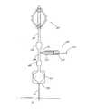
ここで図面を参照すると、図1は、流体定量供給装置および方法の一実施形態の概略図を示す。装置は、局部麻酔薬などの医用流体を保持する加圧した流体源またはポンプ102を備える。ポンプ102は、医用流体を導管104に通らせる。導管104は、連続した、すなわち主要なフローパス106内に、また、患者Pの創傷部位神経束または血流への送出のために、制御されたボーラスフローパス108内に分離する。大容量ボーラスリザーバ110は、ボーラスフローパス108から大量の流体を蓄積し、患者P内に放出するために、一回投与量がアクチュエータ112によってトリガーされるまで、圧力下で流体を保持する。ボーラスリザーバ110から下流で、連続フローパス106およびボーラス投与フローパス108は、患者Pへの単一フローパス114に集まる。Detailed Description of Preferred Embodiments
Referring now to the drawings, FIG. 1 shows a schematic diagram of one embodiment of a fluid metering device and method. The apparatus comprises a pressurized fluid source or pump 102 that holds a medical fluid such as a local anesthetic. Pump 102 passes medical fluid through
ポンプ102は、10〜15psi下で、およそ100〜500mlの流体を蓄積するのが好ましい。ポンプ102は、ハウジング120内のエラストマーチャンバ118によって囲まれた内部コア116を有する。コア116は、ポンプを充填する入り口ポート121および管104と流体連通する出口ポート122を有する。エラストマーチャンバ118は、加硫合成ポリイソプレン、天然ラテックス、天然ゴム、合成ゴム、またはシリコーンゴムを含む、当技術分野でよく知られている種々のエラストマー成分を含み得る弾性材料から作られるのが好ましい。流体は、エラストマーチャンバ118内で圧力下で保持され、制御されかつ予測可能な流量で、エラストマーチャンバ118から出口ポート122を通って導管104に流れる。別法として、導管104を、流量制限器の役を果たすような大きさに作ることができる。示したポンプ102は、I-Flow Corporationに譲渡された米国特許第5,284,481号(参照により本明細書に援用される)に記載されている。ポンプが、流体に所望の圧力を与えることができる限りにおいて、種々の他の従来のポンプを用いることができる。たとえば、共にI-Flow Corporationに譲渡された米国特許第5,080,652号および第5,105,983号(共に参照により本明細書に援用される)に記載されるポンプ、ならびに、当業者が理解するであろうような、他の製造業
者が提供する、他の適当な電子または機械ポンプを用いることもできる。The
任意選択のクランプ124は、導管104から下流で、フローパス106に位置する。クランプ124は、ポンプ102からの流体の流れを閉塞するように、フローパス106を圧縮することができる。こうした閉塞は、本明細書で記載される流体送出装置および方法の輸送および準備にとって有利である。示したクランプ124はまた、I-Flow Corporationに譲渡された米国特許第9,363,228号(参照により本明細書に援用される)に記載されている。しかし、圧縮クランプ、Cクランプ、ローラクランプなどのような、業界で知られている種々の他の従来のクランプを用いて、ポンプ102からフローパス106を通る流体の流れを閉塞させることができる。 An
クランプ124の下流の任意選択のフィルタ126は、流体内で見つかる可能性がある汚染物質および他の好ましくない粒子から流体を分離する。フィルタ126はまた、フローパス106から空気をなくすのが好ましい。1つのこうしたフィルタ126は、I-Flow
Corporationに譲渡された米国特許第9,363,228号(参照により本明細書に援用される)に記載されている。業界で認められている他の適当なフィルタを用いて、系から、好ましくない粒子を補促し、かつ/または、空気を除去することができる。An
U.S. Pat. No. 9,363,228 assigned to Corporation (incorporated herein by reference). Other suitable filters recognized in the industry can be used to encourage unwanted particles and / or remove air from the system.
流量調節器128は、連続フローパス106に位置する。流量調節器128は、ポンプ102から管106を介した患者Pへの、流体の連続しかつほぼ一定の流量を、好ましくは1時間当たり2〜5ccに設定する。こうした1つの流量調節器128は、I-Flow Corporationに譲渡された米国特許第9,363,228号(参照により本明細書に援用される)に記載されている。限定はしないが、カテーテル130を含む他の適当な流量調節装置を用いて、流体の流れを制御することができる。所望であれば、流量調節器128は、手動で調整可能であり、1時間当たり流体1〜5ccの調整可能な流量制御ディスプレイと共にダイアル、スイッチ、またはレバーを装備してよい。別法として、調整することができない定流量調節器を採用することができる。本明細書で述べた、クランプ124、フィルタ126、および流量調節器128の特定の配置は、例示的であるに過ぎない。こうした要素は、存在する場合、当業者であれば容易に理解されるように、任意の配置で構成することができる。 The
引き続き図1を参照すると、任意選択のクランプ132は、導管104から下流のフローパス108に位置する。クランプ132は、ポンプ102からの流体流が閉塞されるようにフローパス108を圧縮することができる。こうした圧縮は、本発明で述べた流体送出装置および方法の輸送および準備にとって有利である。示したクランプ132はまた、I-Flow Corporationに譲渡された米国特許第9,363,228号(参照によって本明細書に援用される)に記載されている。しかし、上述したように、業界で知られている種々の他の従来のクランプを用いて、ポンプ102からフローパス108を通る流体流を閉塞させることができる。 With continued reference to FIG. 1, an
クランプ132の下流の任意選択のフィルタ134は、流体内で見つかる可能性のある汚染物質および他の好ましくない粒子から流体を分離する。フィルタ134はまた、フローパス108から空気をなくすのが好ましい。こうした1つのフィルタ134は、I-Flow
Corporationに譲渡された米国特許第9,363,228号(参照によって本明細書に援用される)に記載されている。同様に、業界で認められている他の適当なフィルタを用いることもできる。An
U.S. Pat. No. 9,363,228 assigned to Corporation (incorporated herein by reference). Similarly, other suitable filters recognized in the industry can be used.
流量調節器136は、フィルタ134の下流に位置してよいが、本明細書で述ベる、クランプ132、フィルタ134、および流量調節器136の特定の配置構成は、たとえ存在しても、単に例示としてである。流量調節器136は、ボーラスリザーバ110への一
回投与量の充填流量を、およそ1時間当たり5〜10ccの流量に設定する。設計された1つの流量調節器136は、I-Flow Corporationに譲渡された米国特許第9,363,228号(参照によって本明細書に援用される)に記載されている。他の流量調節器を用いることもできる。The
大容量ボーラスリザーバ110は、加硫合成ポリイソプレン、天然ラテックス、天然ゴム、合成ボム、またはシリコーンゴムを含む、当技術分野でよく知られている種々のエラストマー成分を含むことができる弾性材料から構成され、ボーラスリザーバ110に高い弾性を与える。調節器136を通って流れる流体は、制御された流量でボーラスリザーバ110に入るため、リザーバ110は、リザーバが、5または10ccの流体、あるいは、本発明に従って患者Pに投与されるのが安全である任意の他の量などの、最大容量に達するまで膨張する。非弾性容器138は、ボーラスリザーバ110がその最大容量を超えて膨張するのを防止するのが好ましい。別法として、リザーバの弾性力は、容器138の最大容量を制御してよい。 The high
単純な形の、患者が操作可能なアクチュエータ112は、ボーラスリザーバ110から下流のボーラス投与フローパス108に位置するバルブである。ボーラスバルブ112は、押しボタン、止めコック、または他の適当なバルブの形態をとることができる。バルブ112が開くと、一回投与量の流体がボーラスリザーバ110からボーラスフローパス108内に放出される。ボーラス投与フローパス108からの流体および連続フローパス106からの流体は、フローパス114内に、そして、患者P内に流れる。ルアーロック140はフローパス114内に位置してよい。カテーテル130はルアーロック140に接続する。アクチュエータは、バルブ以外の形態をとることができる。たとえば、アクチュエータは、アクチュエータが、(1)流体をチャンバの外に押し出す力を必要としないこと、および、(2)一旦始動すると、患者がさらにアクション行うを必要なく、流体が放出されること、という重要な特性を有する限り、他の形態の放出装置であってよい。A simple form of a patient
患者Pに対する一回投与量の放出流量は、エラストマーボーラスリザーバ110の減圧、バルブ112における圧力勾配、および、カテーテル130またはある他の形態の流量制御管の直径によって制御される。患者Pが、大容量ボーラスリザーバ110からより狭いボーラスフローパス108へ流体を押し出す圧力を与える必要がないことが有利である。むしろ、患者Pは、止めコックを回すか、または、押しボタンを解除して、一回投与量を投与することができる。患者Pが、ボーラスリザ−バ110がその容量に充填される時点の前にボーラスバルブ112を始動する場合、患者Pは、総量より少ないボーラス一回分を受ける。事実上、このことによって、患者Pは、大容量の一回投与量として、指定時間当たりの所望される最大流体量を超える量を自己投与することを防止できる。 The single dose release flow rate for patient P is controlled by the decompression of
所望であれば、バルブ112は、開いたままにしなければならないタイプも可能であり、または、タイミングをとった放出を行うことも可能である。バルブは、圧力に応答し、その結果、開くと、圧力が1psiなどの一定のレベルに降下するまで開いたままになるであろう。 If desired, the
図2は、ばねチャンバとして構成されたボーラスリザーバ210の別の実施形態の図である。この実施形態において、圧縮ばね202がチャンバ210の内部に含まれる。ばね202は、チャンバ210の背面板204および伸縮自在な壁206またはプラテンの間に延在する。チャンバ210が流体を含まない時、ばね202は圧縮されていない。流量調節器136からの流体がチャンバ210に入ると、入ってくる流体が背面板206に圧力を加え、ばね202を圧縮する。ばね202が圧縮されると、ボーラスシリンジチャンバ210は、約2〜6psiの圧力で、約10ccの流体を保持することができる。患者Pがバルブ112を始動すると、一回投与量の流体は、チャンバ210から制御されたボ
ーラスフローパス108内に、そして患者Pに向けて出される(empty)。FIG. 2 is a diagram of another embodiment of a
図3は、ボーラスシリンジ302を利用する、本発明の流体定量供給装置および方法の別の実施形態の略図である。ボーラスシリンジ302は、医療分野では一般に用いられている任意の通常のシリンジを具体化することができる。ロックアウトオリフィス304は、ポンプ102から下流で、シリンジ302から上流のフローパス306に位置する。ロックアウトオリフィス304は、流体の流量を1時間当たり5〜10ccの好ましい流量に設定する。一方向流量制限器および逆流防止弁として役立つ。 FIG. 3 is a schematic diagram of another embodiment of the fluid metering device and method of the present invention utilizing a
図1に示すように、分離した連続フローパス106が用いられるところでは、シリンジ302から下流のフローパス306に位置する逆流防止弁308は、開けるのに、ボーラス充填圧より大きな圧力を必要とする。こうした実施形態では、ポンプ102は、下流へ、分離した連続フローパス106ならびにボーラスフローパス306に流体を押し出す。流体がボーラスフローパス306内に流れるため、流体は、ロックアウトオリフィス304を通って、圧力下で約5〜10ccの流体を保持できるボーラスシリンジチャンバ312内に流れる。 As shown in FIG. 1, where a separate
フローパス306から分離した連続フローパス106がない場合、逆流防止弁308は、連続した流体の流れならびに一回投与量の流体を見込むように構成されることができ、一回投与量の流体は、ボーラスシリンジチャンバ312での充填圧が一定のレベルに達するまで、患者Pへ流れるのを妨げられる。ポンプ102からの流体がロックアウトオリフィス304を通って流れるため、流体の一部は、逆流防止弁308の小さな開口369を通って流れて、1時間当たり1〜5ccの流量で患者Pへ流体が連続して投与される。残りの流体は、逆流防止弁308を通って流れるのを妨げられ、ボーラスシリンジチャンバ312の入り口ポート310内に流れる。逆流防止弁308は、開くのに、ボーラス充填圧を超える圧力を必要とする。 In the absence of a
シリンジ302のプランジャ314は、把持および圧迫用に通常のT形状を有する。ボーラスリザーバチャンバ312が流体を含んでいない時、プランジャ314は、シリンジ316の遠位端と同一平面上である。ボーラスリザーバチャンバ312が約1〜30ccの流体の容量に充填されると、プランジャ314は、シリンジ316の遠位端から離れて延びる。一回投与量が投与される時、プランジャ314は、シリンジ316の方に手で押し下げられることができ、それによって、チャンバ312内の流体に圧力がかかる。これによって、シリンジチャンバ312内の流体は、シリンジチャンバ312から出口ポート310を通って、フローパス306に出る。ロックアウトオリフィス304は、一回投与量が、上流へポンプ102に向けて流れるのを防止し、それによって、下流へ逆流防止弁308に向けて運ばれる。一回投与量の圧力は、バルブ308の第2導管または開口を強制的に開けて、ボーラスの流体がバルブ308を通ってチャンバアキュミュレータ318内に流れる。これによって、患者Pがシリンジプランジャ314を押し下げ続ける必要がないように、シリンジチャンバ312が空になる。それによって、プランジャ314を押し下げるのに加えなければならない力も緩和される。 The
チャンバアキュミュレータ318は、非弾性容器320内に収容されたエラストマー球の形態をとることができるが、チャンバアキュミュレータ318は、この特定の形態をとる必要はない。カテーテル322または他の何らかの形態の流量制御導管が、チャンバアキュミュレータ318の下流に位置してもよく、カテーテル322は、プランジャ314が押し下げられる速さに関係なく、予測可能な流量で、好ましくは、5分にわたって流体10ccの最大流量で、患者Pに流体を定量供給する直径を有する。本発明のこの実施形態は、予測可能な期間にわたって、局部麻酔薬および複数回分の服用量のある抗生物質を安全に投与するのにうまく働き、こうした大容量の一回投与量の投与における人的エラー
および不正確さを無効にするのに役立つ。The
本発明は、一定の好ましい実施形態および実施例の状況で述べてきたが、本発明が、具体的に開示した実施形態を超えて、他の代替の実施形態、および/または、本発明および明らかな変更形態およびその等価物の使用に及ぶことを、当業者は理解するであろう。したがって、本明細書に開示した本発明の範囲は、上述した特定の開示した実施形態によって限定されるべきではなく、添付特許請求の範囲を公平に読むことによってのみ決められるべきであることが意図される。 Although the invention has been described in the context of certain preferred embodiments and examples, the invention extends beyond the specifically disclosed embodiments to other alternative embodiments and / or the invention and obvious Those skilled in the art will understand that this extends to the use of various modifications and equivalents thereof. Accordingly, it is intended that the scope of the invention disclosed herein should not be limited by the particular disclosed embodiments described above, but only determined by reading the appended claims fairly. Is done.
Claims (9)
Translated fromJapanese前記流体源と流体連通し、連続的にかつほぼ一定の流体流量を患者に供給する連続フローパスと、
前記連続フローパスを通って患者へ供給される前記流体流量を設定する流量調節器と、
前記流体源と流体連通し、一回投与量の流体を患者に供給するボーラスフローパスと、
前記ボーラスフローパスと流体連通し、前記第一のリザーバからの流体が流入するように構成された、大容量ボーラスリザーバと、
流体を前記ボーラスリザーバから放出するための、患者が操作可能なアクチュエータとを含む、患者に流体を供給する装置であって、
前記流量調節器は、連続フローパス内に配置され、
前記ボーラスリザーバは、前記第一のリザーバから流入する流体の圧力下で弾性的に膨張して加圧された流体を保持し、加圧された流体を放出するように構成され、
前記アクチュエータは、流体を前記ボーラスリザーバから押し出す力を必要とせず、かつ、患者が始動させると、一回投与量の流体を前記ボーラスリザーバから放出させ続けるために患者がさらにアクションすることなしで、流体が前記ボーラスリザーバから患者へ流れ出すことが可能になるように構成されている、装置。A first reservoir configured toprovide a fluid source under pressure;
A continuous flow path in fluid communication with the fluid source and providing a continuous and substantially constant fluid flow rate to the patient;
A flow regulator for setting the fluid flow rate delivered to the patient through the continuous flow path;
The fluid source and fluid communication, andRubo over Las flow path tosupply a single dose of fluidto a patient,
A large volume bolus reservoir in fluid communication with the bolus flow path and configured to receive fluid from the first reservoir;
For releasing fluid from the bolus reservoir,an apparatus for supplying fluid and a patient-operable actuatorincluding a patient,
The flow regulator is disposed in a continuous flow path;
The bolus reservoir is configured to elastically expand and hold pressurized fluid under pressure offluid flowing from the first reservoir and torelease pressurized fluid;
The actuator does not require a force to push fluid out of the bolus reservoir, and when the patient starts, without further action by the patientto continue releasing asingle dose of fluid from the bolus reservoir , fluidhas been configured so as to be able to flow out to the patient from the bolusreservoir device.
ーラス容量の流体を、圧力下で保持するためのエラストマーチャンバを含む、請求項1〜5の何れか一項に記載の装置。The bolus reservoir is to bereleased into the patient at a controlled flow rate in response to the request, the fluid bolus volume, includes an elastomeric chamber for holding under pressure, any one of claims 1 to5 The device described in 1.
Applications Claiming Priority (2)
| Application Number | Priority Date | Filing Date | Title |
|---|---|---|---|
| US29507001P | 2001-06-01 | 2001-06-01 | |
| PCT/US2002/017155WO2002098493A1 (en) | 2001-06-01 | 2002-05-31 | Large volume bolus device and method |
Publications (3)
| Publication Number | Publication Date |
|---|---|
| JP2004528137A JP2004528137A (en) | 2004-09-16 |
| JP2004528137A5 JP2004528137A5 (en) | 2006-01-05 |
| JP4398723B2true JP4398723B2 (en) | 2010-01-13 |
Family
ID=23136084
Family Applications (1)
| Application Number | Title | Priority Date | Filing Date |
|---|---|---|---|
| JP2003501530AExpired - LifetimeJP4398723B2 (en) | 2001-06-01 | 2002-05-31 | Large-capacity bolus device |
Country Status (13)
| Country | Link |
|---|---|
| US (2) | US6981967B2 (en) |
| EP (1) | EP1395315B1 (en) |
| JP (1) | JP4398723B2 (en) |
| KR (1) | KR100797144B1 (en) |
| CN (1) | CN100402100C (en) |
| AT (1) | ATE366125T1 (en) |
| AU (1) | AU2002259324B2 (en) |
| CA (1) | CA2448692C (en) |
| DE (1) | DE60221012T2 (en) |
| ES (1) | ES2287275T3 (en) |
| MX (1) | MXPA03011015A (en) |
| PT (1) | PT1395315E (en) |
| WO (1) | WO2002098493A1 (en) |
Families Citing this family (92)
| Publication number | Priority date | Publication date | Assignee | Title |
|---|---|---|---|---|
| US7311693B2 (en)* | 2001-11-26 | 2007-12-25 | Nilimedix Ltd. | Drug delivery device and method |
| FR2834442B1 (en)* | 2002-01-07 | 2004-10-08 | Saphir Medical | APPARATUS FOR MICRODOSE INJECTION OF AN ACTIVE PRODUCT BY PRESSURE WORKING LIQUID JETS AND METHOD FOR GENERATING A SEQUENCE OF LIQUID JETS USING THE SAME |
| US7794436B2 (en)* | 2004-01-13 | 2010-09-14 | Lloyd Jay Pinel | Controlled gastric bolus feeding device |
| US7364571B2 (en)* | 2004-03-02 | 2008-04-29 | Schinazi Robert G | Flow restrictor device for a medical apparatus |
| JP4539382B2 (en)* | 2004-03-12 | 2010-09-08 | ニプロ株式会社 | Patient controlled analgesia (PCA) device with continuous infusion and additional administration |
| KR100919651B1 (en)* | 2004-03-12 | 2009-09-30 | 니프로 가부시키가이샤 | Pca device which is capable of persistently infusing and additionally administrating drug |
| US20050267413A1 (en)* | 2004-05-26 | 2005-12-01 | Wang Jong H | Flow monitoring devices and methods of use |
| US8961461B2 (en) | 2004-05-27 | 2015-02-24 | Baxter International Inc. | Multi-state alarm system for a medical pump |
| US20050277873A1 (en)* | 2004-05-27 | 2005-12-15 | Janice Stewart | Identification information recognition system for a medical device |
| US7927313B2 (en)* | 2004-05-27 | 2011-04-19 | Baxter International Inc. | Medical device configuration based on recognition of identification information |
| CN100488444C (en)* | 2004-08-19 | 2009-05-20 | 迪拉莫有限公司 | Micro-analysis system |
| AU2005306461B2 (en)* | 2004-11-19 | 2011-01-20 | Curlin Medical Inc. | Controlled-volume infusion device |
| US7325572B2 (en) | 2005-12-09 | 2008-02-05 | Schinazi Robert G | Flow restrictor device for a medical apparatus |
| US20070264130A1 (en)* | 2006-01-27 | 2007-11-15 | Phluid, Inc. | Infusion Pumps and Methods for Use |
| US8211054B2 (en) | 2006-05-01 | 2012-07-03 | Carefusion 303, Inc. | System and method for controlling administration of medical fluid |
| EP2173412A4 (en) | 2007-07-06 | 2011-07-27 | Allievion Medical Inc | Constrained fluid delivery device |
| US8215157B2 (en)* | 2007-10-04 | 2012-07-10 | Baxter International Inc. | System and method for measuring liquid viscosity in a fluid delivery system |
| US20090093774A1 (en)* | 2007-10-04 | 2009-04-09 | Baxter International Inc. | Ambulatory pump with intelligent flow control |
| WO2009073434A1 (en)* | 2007-11-29 | 2009-06-11 | Guzman Michael F | Pain management methods and apparatus |
| US8211091B2 (en) | 2007-11-29 | 2012-07-03 | Guzman Michael F | Method and apparatus for charging pump with local anesthetic |
| US8328787B2 (en) | 2007-11-29 | 2012-12-11 | Guzman Michael F | Pain management methods and apparatus |
| US20090149838A1 (en)* | 2007-12-10 | 2009-06-11 | Cassada David C | Subcutaneous Implant System |
| US8986253B2 (en)* | 2008-01-25 | 2015-03-24 | Tandem Diabetes Care, Inc. | Two chamber pumps and related methods |
| WO2009143188A2 (en)* | 2008-05-19 | 2009-11-26 | Diperna Paul M | Disposable pump reservoir and related methods |
| US8408421B2 (en) | 2008-09-16 | 2013-04-02 | Tandem Diabetes Care, Inc. | Flow regulating stopcocks and related methods |
| CA2737461A1 (en)* | 2008-09-19 | 2010-03-25 | Tandem Diabetes Care, Inc. | Solute concentration measurement device and related methods |
| EP2334354A4 (en)* | 2008-10-15 | 2014-01-22 | Symbios Medical Products Llc | Electronic flow control |
| US8052656B2 (en)* | 2009-02-10 | 2011-11-08 | Tyco Healthcare Group Lp | Enteral feeding system |
| CN102481431B (en) | 2009-06-05 | 2015-09-16 | 费雪派克医疗保健有限公司 | The heater support of humidifier |
| EP2724739B1 (en) | 2009-07-30 | 2015-07-01 | Tandem Diabetes Care, Inc. | Portable infusion pump system |
| KR101104800B1 (en)* | 2010-01-20 | 2012-01-12 | 전우람 | Golf Putting Practice Device |
| US9265913B2 (en) | 2010-09-22 | 2016-02-23 | Vital 5, Llc | Catheter assembly |
| US20130109987A1 (en)* | 2011-05-12 | 2013-05-02 | Medical Device Innovations Inc. | Method and device for treatment of arrhythmias and other maladies |
| US8814829B2 (en) | 2010-08-12 | 2014-08-26 | Baxter International Inc. | Drug delivery device for fluid restricted patients |
| US9132233B2 (en)* | 2010-08-26 | 2015-09-15 | B. Braun Melsungen Ag | Infusion control device |
| US9446224B2 (en) | 2010-09-22 | 2016-09-20 | Vital 5, L.L.C. | Barrier catheter |
| AU2015268574B2 (en)* | 2010-12-10 | 2017-01-19 | Avent, Inc. | Infusion apparatus with flow indicator |
| US8308688B2 (en)* | 2010-12-15 | 2012-11-13 | Kimberly-Clark Worldwide, Inc | Large-volume bolus patient controlled drug administration device |
| US8753315B2 (en)* | 2011-02-17 | 2014-06-17 | Calibra Medical, Inc. | Manual basal bolus drug delivery device |
| US8986283B2 (en) | 2011-05-18 | 2015-03-24 | Solo-Dex, Llc | Continuous anesthesia nerve conduction apparatus, system and method thereof |
| CA3065357C (en) | 2011-05-18 | 2023-04-25 | Solodex Llc | Continuous anesthesia nerve conduction apparatus, system and method |
| US20120291540A1 (en)* | 2011-05-20 | 2012-11-22 | Cooke Dominic J | Infusion Apparatus With Flow Detector |
| USD679804S1 (en) | 2011-09-22 | 2013-04-09 | Vital 5, Llc | Catheter |
| US9180242B2 (en) | 2012-05-17 | 2015-11-10 | Tandem Diabetes Care, Inc. | Methods and devices for multiple fluid transfer |
| US20130310770A1 (en)* | 2012-05-17 | 2013-11-21 | Dominic J. Cooke | Infusion Apparatus With Composition Pulse Flow Sensor |
| US9555186B2 (en) | 2012-06-05 | 2017-01-31 | Tandem Diabetes Care, Inc. | Infusion pump system with disposable cartridge having pressure venting and pressure feedback |
| US9320846B2 (en) | 2012-08-28 | 2016-04-26 | Osprey Medical, Inc. | Devices and methods for modulating medium delivery |
| US10022497B2 (en) | 2012-08-28 | 2018-07-17 | Osprey Medical, Inc. | Reservoir for collection and reuse of diverted medium |
| US9999718B2 (en) | 2012-08-28 | 2018-06-19 | Osprey Medical, Inc. | Volume monitoring device utilizing light-based systems |
| US11219719B2 (en) | 2012-08-28 | 2022-01-11 | Osprey Medical, Inc. | Volume monitoring systems |
| US10010673B2 (en) | 2012-08-28 | 2018-07-03 | Osprey Medical, Inc. | Adjustable medium diverter |
| US10413677B2 (en) | 2012-08-28 | 2019-09-17 | Osprey Medical, Inc. | Volume monitoring device |
| US11116892B2 (en) | 2012-08-28 | 2021-09-14 | Osprey Medical, Inc. | Medium injection diversion and measurement |
| WO2014104857A1 (en)* | 2012-12-28 | 2014-07-03 | 메디칸(주) | Static pressure and metering pump |
| US9940441B2 (en) | 2013-03-13 | 2018-04-10 | Tandem Diabetes Care, Inc. | System and method for maximum insulin pump bolus override |
| US9173998B2 (en) | 2013-03-14 | 2015-11-03 | Tandem Diabetes Care, Inc. | System and method for detecting occlusions in an infusion pump |
| US9603995B2 (en) | 2013-03-15 | 2017-03-28 | Tandem Diabetes Care. Inc. | Device and method for setting therapeutic parameters for an infusion device |
| US10933230B2 (en) | 2013-05-06 | 2021-03-02 | Medtronic, Inc. | Systems and methods for implanting a medical electrical lead |
| WO2015112810A1 (en) | 2014-01-24 | 2015-07-30 | Avent, Inc. | Traumatic wound dressing system with conformal cover |
| AU2015209240B2 (en) | 2014-01-24 | 2019-06-13 | Avent, Inc. | Traumatic wound dressing system with wrap |
| US10173003B2 (en)* | 2014-03-07 | 2019-01-08 | Carefusion 303, Inc. | Syringe flush protection valve and method |
| DE102014212237A1 (en)* | 2014-06-25 | 2015-12-31 | B. Braun Melsungen Ag | Device for administering fluid to a patient |
| US20160051755A1 (en)* | 2014-08-25 | 2016-02-25 | Medtronic Minimed, Inc. | Low cost fluid delivery device |
| CA2959330C (en) | 2014-08-26 | 2022-12-13 | Avent, Inc. | Selective nerve fiber block method and system |
| EP3197524B1 (en) | 2014-09-22 | 2021-10-27 | Becton, Dickinson and Company | Plate with integral fluid path channels |
| US10729456B2 (en) | 2014-12-18 | 2020-08-04 | Medtronic, Inc. | Systems and methods for deploying an implantable medical electrical lead |
| FR3032264B1 (en)* | 2015-02-02 | 2017-03-03 | Degremont | METHOD FOR MANAGING AIR FLOW OF A MECHANICAL SLUDGE DEHYDRATION, AND DEVICE THEREFOR |
| KR101798429B1 (en)* | 2015-07-08 | 2017-12-12 | 주식회사 더블유앤지 | A device for injecting drugs |
| DE102015213726A1 (en)* | 2015-07-21 | 2017-01-26 | B. Braun Melsungen Ag | Actuator for bolus administration |
| MX2018001262A (en) | 2015-08-27 | 2018-04-13 | Avent Inc | Variable fluid flow rate control device. |
| WO2017034568A1 (en)* | 2015-08-27 | 2017-03-02 | Avent, Inc. | Variable flow rate control device |
| ES2857153T3 (en) | 2015-09-21 | 2021-09-28 | Becton Dickinson Co | Diagram of fluid interconnection between reservoir, pump and filling member |
| CN108367115A (en)* | 2015-12-17 | 2018-08-03 | 阿文特公司 | With the infusion pump for extending sensor |
| CN109069732B (en) | 2016-02-22 | 2021-09-14 | L2R企业有限责任公司 | Microfluidic flow restrictor assembly and method of making same |
| KR101739368B1 (en)* | 2016-03-17 | 2017-06-08 | 주식회사 우영메디칼 | Medical Fluid Injector Having Multi-Type Flow Rate Controlling Apparatus |
| KR101640481B1 (en) | 2016-05-25 | 2016-07-18 | 김준우 | Injection Device For Medical Use |
| JP2020503111A (en) | 2016-12-27 | 2020-01-30 | アヴェント インコーポレイテッド | Articles and methods for treating diabetic peripheral neuropathy |
| DE102017205251A1 (en) | 2017-03-28 | 2018-10-04 | B. Braun Melsungen Ag | Medical pump device |
| AU2018281816A1 (en) | 2017-06-07 | 2019-12-12 | Avent, Inc. | Bolus delivery device |
| EP3635737A1 (en) | 2017-06-08 | 2020-04-15 | Edwards Lifesciences Corporation | Assisted fluid delivery system and method |
| KR102085515B1 (en)* | 2018-02-27 | 2020-03-05 | 주식회사 이화메디텍 | Device for regulating liquid medicine supply and medicine injection apparatus comprising the same |
| US10792496B2 (en) | 2018-03-15 | 2020-10-06 | Avent, Inc. | System and method to percutaneously block painful sensations |
| CN108478896B (en)* | 2018-04-11 | 2023-07-28 | 刘玮 | Universal type pressure-reducing and centralized-control automatic bottle changing device for medical transfusion |
| CN109675139A (en)* | 2019-01-29 | 2019-04-26 | 刘静 | Medical fluid infusion component and system |
| US11357209B2 (en)* | 2019-02-01 | 2022-06-14 | Henry Bennie Marshall, III | Pet bed platform with air filtration system |
| US11623091B2 (en) | 2019-02-13 | 2023-04-11 | Avent, Inc. | Portable electrical stimulation system and method |
| WO2020210623A1 (en) | 2019-04-12 | 2020-10-15 | Osprey Medical Inc. | Energy-efficient position determining with multiple sensors |
| JP2020185128A (en)* | 2019-05-14 | 2020-11-19 | オーベクス株式会社 | Chemical self-injection system |
| DE102019217315A1 (en)* | 2019-11-08 | 2021-05-12 | B. Braun Melsungen Aktiengesellschaft | Infusion system, rotor module for use in such an infusion system and method for determining a flow rate of an infusion liquid in such an infusion system |
| KR102196122B1 (en) | 2019-12-06 | 2020-12-29 | 주식회사 유니메딕스 | Patient controlled drug administration device |
| KR102203629B1 (en)* | 2020-02-29 | 2021-01-15 | 주식회사 이화메디텍 | Device for regulating liquid medicine supply and medicine injection apparatus comprising the same |
| KR102190535B1 (en) | 2020-07-08 | 2020-12-14 | 주식회사 유니메딕스 | Multifunctional bolus |
Family Cites Families (36)
| Publication number | Priority date | Publication date | Assignee | Title |
|---|---|---|---|---|
| US2471623A (en)* | 1944-12-19 | 1949-05-31 | Adrian O Hubbell | Apparatus for handling fluids |
| US4121584A (en)* | 1976-10-15 | 1978-10-24 | R. Scott Turner | Method and apparatus for controlling the dispensing of fluid |
| US4193397A (en)* | 1977-12-01 | 1980-03-18 | Metal Bellows Corporation | Infusion apparatus and method |
| US4432754A (en)* | 1982-05-24 | 1984-02-21 | Alza Corporation | Apparatus for parenteral infusion of fluid containing beneficial agent |
| US4447224A (en)* | 1982-09-20 | 1984-05-08 | Infusaid Corporation | Variable flow implantable infusion apparatus |
| US4573974A (en)* | 1982-12-01 | 1986-03-04 | Baxter Travenol Laboratories, Inc. | Medical administration set enabling sequential delivery of two liquids at different flow rate |
| DE3577039D1 (en)* | 1984-06-21 | 1990-05-17 | David R Fischell | FINGER-ACTUATED INFUSION SYSTEM FOR THE MEDICAL SUPPLY. |
| US4634427A (en)* | 1984-09-04 | 1987-01-06 | American Hospital Supply Company | Implantable demand medication delivery assembly |
| US4953753A (en) | 1988-06-10 | 1990-09-04 | The Norman Company | Fluid dispensing apparatus with prestressed bladder |
| JP2876611B2 (en)* | 1989-01-25 | 1999-03-31 | ソニー株式会社 | Recording method for write-once optical disc |
| US5011477A (en) | 1989-04-21 | 1991-04-30 | Baxter International Inc. | Continuous/bolus infusor |
| US5080652A (en)* | 1989-10-31 | 1992-01-14 | Block Medical, Inc. | Infusion apparatus |
| JPH03178669A (en) | 1989-12-08 | 1991-08-02 | Sugino Mach Ltd | Drug injection injection device |
| CN2066329U (en)* | 1990-02-15 | 1990-11-28 | 殷乐平 | Dual-channel disposable transfusion device |
| DE69022989T2 (en) | 1990-02-28 | 1996-03-14 | Tsukada Medical Research Co | INJECTOR WITH BALLOON FOR CONTINUOUS INJECTION OF A MEDICINAL SOLUTION. |
| US5152753A (en) | 1990-04-02 | 1992-10-06 | Pudenz-Schulte Medical Research Corporation | Medication infusion device with dose recharge restriction |
| US5084021A (en)* | 1990-11-02 | 1992-01-28 | Baldwin Brian E | Patient controlled infusion apparatus and method |
| JP2712907B2 (en)* | 1991-07-10 | 1998-02-16 | 株式会社ニッショー | Apparatus for self-injecting a drug solution and device using the same |
| US5224934A (en) | 1991-12-06 | 1993-07-06 | Block Medical, Inc. | Patient controlled bolus dosage infuser |
| US5911716A (en)* | 1992-01-24 | 1999-06-15 | I-Flow Corporation | Platen pump |
| CA2168554A1 (en)* | 1993-08-11 | 1995-02-16 | Thomas John Berrigan | Implantable drug delivery means |
| BR9304747A (en) | 1993-11-17 | 1995-07-11 | Claro Jorge Antonio Rodrigues | Medicine injector |
| US6213972B1 (en) | 1994-09-13 | 2001-04-10 | Alaris Medical Systems, Inc. | Fluid flow resistance monitoring system |
| US5505707A (en) | 1994-12-01 | 1996-04-09 | Northgate Technologies, Inc. | Tubing system with pump for delivering continuous fluid flow or fluid bolus to a surgical site |
| US5776105A (en)* | 1995-09-28 | 1998-07-07 | Children's Medical Center Corp. | Ambulatory intravenous fluid holder |
| US5830187A (en) | 1995-12-22 | 1998-11-03 | Science Incorporated | Fluid delivery device with conformable ullage and fill assembly |
| CN2242699Y (en)* | 1996-01-18 | 1996-12-18 | 山东省滨州地区人民医院 | Multi-function infusion device |
| WO1997033637A1 (en) | 1996-03-14 | 1997-09-18 | O'neil, Christine | Patient controllable drug delivery system flow regulating means |
| JP3147347B2 (en) | 1996-04-23 | 2001-03-19 | 株式会社ニッショー | Chemical self-injection tool |
| US5807312A (en)* | 1997-05-23 | 1998-09-15 | Dzwonkiewicz; Mark R. | Bolus pump apparatus |
| US5957895A (en)* | 1998-02-20 | 1999-09-28 | Becton Dickinson And Company | Low-profile automatic injection device with self-emptying reservoir |
| JP3928248B2 (en) | 1998-02-27 | 2007-06-13 | ニプロ株式会社 | Chemical liquid self-injection tool |
| US5906597A (en) | 1998-06-09 | 1999-05-25 | I-Flow Corporation | Patient-controlled drug administration device |
| JP3073979B1 (en) | 1999-03-15 | 2000-08-07 | 大研医器株式会社 | Chemical injection device |
| US6471675B1 (en)* | 1999-04-30 | 2002-10-29 | Medtronic, Inc. | Passive flow control devices for implantable pumps |
| WO2000071190A1 (en)* | 1999-05-24 | 2000-11-30 | Tsukada Medical Research Co., Ltd. | Portable pain relieving device |
- 2002
- 2002-05-31WOPCT/US2002/017155patent/WO2002098493A1/enactiveIP Right Grant
- 2002-05-31CACA002448692Apatent/CA2448692C/ennot_activeExpired - Lifetime
- 2002-05-31DEDE60221012Tpatent/DE60221012T2/ennot_activeExpired - Lifetime
- 2002-05-31CNCNB028152190Apatent/CN100402100C/ennot_activeExpired - Lifetime
- 2002-05-31MXMXPA03011015Apatent/MXPA03011015A/enactiveIP Right Grant
- 2002-05-31JPJP2003501530Apatent/JP4398723B2/ennot_activeExpired - Lifetime
- 2002-05-31AUAU2002259324Apatent/AU2002259324B2/ennot_activeCeased
- 2002-05-31EPEP02729327Apatent/EP1395315B1/ennot_activeExpired - Lifetime
- 2002-05-31PTPT02729327Tpatent/PT1395315E/enunknown
- 2002-05-31ATAT02729327Tpatent/ATE366125T1/ennot_activeIP Right Cessation
- 2002-05-31ESES02729327Tpatent/ES2287275T3/ennot_activeExpired - Lifetime
- 2002-05-31KRKR1020037015765Apatent/KR100797144B1/ennot_activeExpired - Fee Related
- 2002-06-03USUS10/162,089patent/US6981967B2/ennot_activeExpired - Lifetime
- 2005
- 2005-12-29USUS11/321,197patent/US7815604B2/ennot_activeExpired - Lifetime
Also Published As
| Publication number | Publication date |
|---|---|
| US20030040722A1 (en) | 2003-02-27 |
| MXPA03011015A (en) | 2004-03-19 |
| US6981967B2 (en) | 2006-01-03 |
| WO2002098493A1 (en) | 2002-12-12 |
| EP1395315A1 (en) | 2004-03-10 |
| JP2004528137A (en) | 2004-09-16 |
| KR20040014543A (en) | 2004-02-14 |
| ATE366125T1 (en) | 2007-07-15 |
| CA2448692C (en) | 2008-10-07 |
| US20060106367A1 (en) | 2006-05-18 |
| DE60221012T2 (en) | 2008-03-13 |
| PT1395315E (en) | 2007-08-21 |
| CN100402100C (en) | 2008-07-16 |
| US7815604B2 (en) | 2010-10-19 |
| EP1395315B1 (en) | 2007-07-04 |
| CA2448692A1 (en) | 2002-12-12 |
| CN1538859A (en) | 2004-10-20 |
| HK1070599A1 (en) | 2005-06-24 |
| AU2002259324B2 (en) | 2006-09-07 |
| KR100797144B1 (en) | 2008-01-22 |
| ES2287275T3 (en) | 2007-12-16 |
| DE60221012D1 (en) | 2007-08-16 |
Similar Documents
| Publication | Publication Date | Title |
|---|---|---|
| JP4398723B2 (en) | Large-capacity bolus device | |
| AU2002259324A1 (en) | Large volume bolus device and method | |
| KR101869529B1 (en) | Improved large-volume bolus patient controlled drug administration device | |
| US12390582B2 (en) | Priming system for infusion devices | |
| JP2002517287A (en) | Patient control drug dosing device | |
| US5232448A (en) | Patient-controlled analgesia device | |
| US9649434B2 (en) | Large-volume bolus patient controlled drug administration device with lock-out | |
| US20230048874A1 (en) | Variable Fluid Flow Rate Control Device | |
| JP2552692B2 (en) | Drug supply device | |
| HK1070599B (en) | Large volume bolus device and method |
Legal Events
| Date | Code | Title | Description |
|---|---|---|---|
| A521 | Request for written amendment filed | Free format text:JAPANESE INTERMEDIATE CODE: A523 Effective date:20050530 | |
| A621 | Written request for application examination | Free format text:JAPANESE INTERMEDIATE CODE: A621 Effective date:20050530 | |
| A131 | Notification of reasons for refusal | Free format text:JAPANESE INTERMEDIATE CODE: A131 Effective date:20080708 | |
| A521 | Request for written amendment filed | Free format text:JAPANESE INTERMEDIATE CODE: A523 Effective date:20081008 | |
| A02 | Decision of refusal | Free format text:JAPANESE INTERMEDIATE CODE: A02 Effective date:20090310 | |
| A521 | Request for written amendment filed | Free format text:JAPANESE INTERMEDIATE CODE: A523 Effective date:20090608 | |
| A911 | Transfer to examiner for re-examination before appeal (zenchi) | Free format text:JAPANESE INTERMEDIATE CODE: A911 Effective date:20090819 | |
| TRDD | Decision of grant or rejection written | ||
| A01 | Written decision to grant a patent or to grant a registration (utility model) | Free format text:JAPANESE INTERMEDIATE CODE: A01 Effective date:20090929 | |
| A01 | Written decision to grant a patent or to grant a registration (utility model) | Free format text:JAPANESE INTERMEDIATE CODE: A01 | |
| A61 | First payment of annual fees (during grant procedure) | Free format text:JAPANESE INTERMEDIATE CODE: A61 Effective date:20091023 | |
| FPAY | Renewal fee payment (event date is renewal date of database) | Free format text:PAYMENT UNTIL: 20121030 Year of fee payment:3 | |
| R150 | Certificate of patent or registration of utility model | Free format text:JAPANESE INTERMEDIATE CODE: R150 Ref document number:4398723 Country of ref document:JP Free format text:JAPANESE INTERMEDIATE CODE: R150 | |
| RD02 | Notification of acceptance of power of attorney | Free format text:JAPANESE INTERMEDIATE CODE: R3D02 | |
| FPAY | Renewal fee payment (event date is renewal date of database) | Free format text:PAYMENT UNTIL: 20121030 Year of fee payment:3 | |
| S531 | Written request for registration of change of domicile | Free format text:JAPANESE INTERMEDIATE CODE: R313531 | |
| S533 | Written request for registration of change of name | Free format text:JAPANESE INTERMEDIATE CODE: R313533 | |
| S111 | Request for change of ownership or part of ownership | Free format text:JAPANESE INTERMEDIATE CODE: R313113 | |
| FPAY | Renewal fee payment (event date is renewal date of database) | Free format text:PAYMENT UNTIL: 20121030 Year of fee payment:3 | |
| R350 | Written notification of registration of transfer | Free format text:JAPANESE INTERMEDIATE CODE: R350 | |
| FPAY | Renewal fee payment (event date is renewal date of database) | Free format text:PAYMENT UNTIL: 20121030 Year of fee payment:3 | |
| R350 | Written notification of registration of transfer | Free format text:JAPANESE INTERMEDIATE CODE: R350 | |
| FPAY | Renewal fee payment (event date is renewal date of database) | Free format text:PAYMENT UNTIL: 20121030 Year of fee payment:3 | |
| FPAY | Renewal fee payment (event date is renewal date of database) | Free format text:PAYMENT UNTIL: 20131030 Year of fee payment:4 | |
| R250 | Receipt of annual fees | Free format text:JAPANESE INTERMEDIATE CODE: R250 | |
| R250 | Receipt of annual fees | Free format text:JAPANESE INTERMEDIATE CODE: R250 | |
| R250 | Receipt of annual fees | Free format text:JAPANESE INTERMEDIATE CODE: R250 | |
| R250 | Receipt of annual fees | Free format text:JAPANESE INTERMEDIATE CODE: R250 | |
| S111 | Request for change of ownership or part of ownership | Free format text:JAPANESE INTERMEDIATE CODE: R313113 | |
| R350 | Written notification of registration of transfer | Free format text:JAPANESE INTERMEDIATE CODE: R350 | |
| R250 | Receipt of annual fees | Free format text:JAPANESE INTERMEDIATE CODE: R250 | |
| R250 | Receipt of annual fees | Free format text:JAPANESE INTERMEDIATE CODE: R250 | |
| R250 | Receipt of annual fees | Free format text:JAPANESE INTERMEDIATE CODE: R250 | |
| R250 | Receipt of annual fees | Free format text:JAPANESE INTERMEDIATE CODE: R250 | |
| R250 | Receipt of annual fees | Free format text:JAPANESE INTERMEDIATE CODE: R250 | |
| R250 | Receipt of annual fees | Free format text:JAPANESE INTERMEDIATE CODE: R250 | |
| EXPY | Cancellation because of completion of term |