JP4396511B2 - Printing system - Google Patents
Printing systemDownload PDFInfo
- Publication number
- JP4396511B2 JP4396511B2JP2004368317AJP2004368317AJP4396511B2JP 4396511 B2JP4396511 B2JP 4396511B2JP 2004368317 AJP2004368317 AJP 2004368317AJP 2004368317 AJP2004368317 AJP 2004368317AJP 4396511 B2JP4396511 B2JP 4396511B2
- Authority
- JP
- Japan
- Prior art keywords
- stand
- camera
- digital still
- printer
- still camera
- Prior art date
- Legal status (The legal status is an assumption and is not a legal conclusion. Google has not performed a legal analysis and makes no representation as to the accuracy of the status listed.)
- Expired - Fee Related
Links
Images


Classifications
- H—ELECTRICITY
- H04—ELECTRIC COMMUNICATION TECHNIQUE
- H04N—PICTORIAL COMMUNICATION, e.g. TELEVISION
- H04N1/00—Scanning, transmission or reproduction of documents or the like, e.g. facsimile transmission; Details thereof
- H04N1/00127—Connection or combination of a still picture apparatus with another apparatus, e.g. for storage, processing or transmission of still picture signals or of information associated with a still picture
- H04N1/00278—Connection or combination of a still picture apparatus with another apparatus, e.g. for storage, processing or transmission of still picture signals or of information associated with a still picture with a printing apparatus, e.g. a laser beam printer
- G—PHYSICS
- G06—COMPUTING OR CALCULATING; COUNTING
- G06F—ELECTRIC DIGITAL DATA PROCESSING
- G06F3/00—Input arrangements for transferring data to be processed into a form capable of being handled by the computer; Output arrangements for transferring data from processing unit to output unit, e.g. interface arrangements
- G06F3/12—Digital output to print unit, e.g. line printer, chain printer
- G—PHYSICS
- G03—PHOTOGRAPHY; CINEMATOGRAPHY; ANALOGOUS TECHNIQUES USING WAVES OTHER THAN OPTICAL WAVES; ELECTROGRAPHY; HOLOGRAPHY
- G03G—ELECTROGRAPHY; ELECTROPHOTOGRAPHY; MAGNETOGRAPHY
- G03G15/00—Apparatus for electrographic processes using a charge pattern
- H—ELECTRICITY
- H04—ELECTRIC COMMUNICATION TECHNIQUE
- H04N—PICTORIAL COMMUNICATION, e.g. TELEVISION
- H04N2201/00—Indexing scheme relating to scanning, transmission or reproduction of documents or the like, and to details thereof
- H04N2201/0008—Connection or combination of a still picture apparatus with another apparatus
- H04N2201/0034—Details of the connection, e.g. connector, interface
- H04N2201/0048—Type of connection
- H04N2201/0058—Docking-station, cradle or the like
- H—ELECTRICITY
- H04—ELECTRIC COMMUNICATION TECHNIQUE
- H04N—PICTORIAL COMMUNICATION, e.g. TELEVISION
- H04N2201/00—Indexing scheme relating to scanning, transmission or reproduction of documents or the like, and to details thereof
- H04N2201/0077—Types of the still picture apparatus
- H04N2201/0084—Digital still camera
Landscapes
- Engineering & Computer Science (AREA)
- Physics & Mathematics (AREA)
- General Physics & Mathematics (AREA)
- Theoretical Computer Science (AREA)
- Multimedia (AREA)
- Signal Processing (AREA)
- Human Computer Interaction (AREA)
- General Engineering & Computer Science (AREA)
- Studio Devices (AREA)
- Accessory Devices And Overall Control Thereof (AREA)
- Television Signal Processing For Recording (AREA)
Description
Translated fromJapanese本発明は、カメラ装置をスタンド装置を介してプリンタ装置に装着することができるプリントシステムに関する。 The present invention relates to a print system in which a camera device can be attached to a printer device via a stand device.
特許文献1に示すように、カメラ装置をプリンタ装置に直接的に装着し、カメラ装置の画像データをプリンタ装置で印刷するシステムがある。また、ディジタルスチルカメラといった小型のカメラ装置は、スタンド装置に装着できるようにもなっている。例えば、小型のカメラ装置は、スタンド装置に装着することで、カメラ装置に内蔵された充電型電池に充電を行うことができ、また、他の電子機器と有線でデータのやり取りを行うことができる。 As shown in Patent Document 1, there is a system in which a camera device is directly mounted on a printer device and image data of the camera device is printed by the printer device. A small camera device such as a digital still camera can be mounted on a stand device. For example, a small camera device can be charged to a rechargeable battery built in the camera device by attaching it to a stand device, and can exchange data with other electronic devices in a wired manner. .
本発明の目的は、カメラ装置が装着されるスタンド装置をプリンタ装置に装着することができる新規なプリントシステムを提供することにある。An object of thepresent invention is to provide a novel printing system that can mount a stand device on which a camera device is mounted on a printer device.
また、本発明の目的は、スタンド装置を見栄え良くプリンタ装置に装着することができるプリントシステムを提供することにある。 It is another object of the present invention to provide a printing system that can be mounted on a printer device with a pleasing appearance.
更に、本発明の目的は、スタンド装置を介してカメラ装置をプリンタ装置に装着した際にカメラ装置のデータをプリンタ装置で印刷することができるようにし、利便性の向上を図ったプリントシステムを提供することにある。 Furthermore, an object of the present invention is to provide a printing system that can improve the convenience by allowing the printer device to print data of the camera device when the camera device is mounted on the printer device via the stand device. There is to do.
本発明に係るプリントシステムは、撮像部と、この撮像部が撮像した画像データを保存するメモリと、充電型電池と、底面部に設けられる第1のスタンドI/Fとを有するカメラ装置と、上記カメラ装置が電気的に接続された状態で装着されるカメラ装着部と、背面部に設けられ他の電子機器と電気的に接続される端子部又は操作部と、上記カメラ装着部に設けられ上記カメラ装置の第1のスタンドI/Fと電気的に接続されるカメラI/Fと、底面部に設けられるプリンタI/Fと、上記カメラ装置の充電型電池の充電を行う充電制御部とを有するスタンド装置と、上記スタンド装置の底面部の形状に対応した凹部で構成され上記スタンド装置が電気的に接続された状態で装着される共通化されたスタンド装着部と、該スタンド装着部に設けられ上記スタンド装置のプリンタI/Fと電気的に接続される第2のスタンドI/Fと、上記スタンド装置から入力された画像データを印刷する印刷部とを有するプリンタ装置とを備える。
上記スタンド装着部には、上記スタンド装置の背面部に設けられた端子部又は操作部を含む上記スタンド装置の背面部と該背面部と隣り合う両側面部を覆う覆い片が設けられている。
上記カメラ装置が上記スタンド装置のカメラ装着部に装着され上記第1のスタンドI/Fと上記カメラI/Fとが電気的に接続され、該スタンド装置が上記プリンタ装置に装着され上記プリンタI/Fと第2のスタンドI/Fとが電気的に接続された状態において、上記スタンド装置の充電制御部は、上記プリンタ装置から供給される充電用電源を上記カメラ装置に供給し、上記カメラ装置の充電型電池の充電を行う。A printing system according to the present invention includes animaging unit, a memory that stores image data captured by the imaging unit, a rechargeable battery, and a camera device having a first stand I / F provided on the bottom surface, A camera mounting unit that is mounted in a state where the camera device is electrically connected, a terminal unit or an operation unit that is provided on the back surface and is electrically connected to another electronic device, and is provided in the camera mounting unit. A camera I / F electrically connected to the first stand I / F of the camera device; a printer I / F provided on the bottom surface; a charge control unit for charging a rechargeable battery of the camera device; A stand device having a recess, corresponding to the shape of the bottom surface of the stand device, and a common stand mounting portion that is mounted in a state where the stand device is electrically connected, and the stand mounting portion. Setting Is provided with a second stand I / F that is the printer I / F electrically connected the stand apparatus, a printer apparatus and a printing unit that prints the image data input from the stand apparatus.
The stand mounting portion is provided with a covering piece that covers a back surface portion of the stand device including a terminal portion or an operation portion provided on a back surface portion of the stand device and both side surface portions adjacent to the back surface portion.
The camera device is mounted on a camera mounting portion of the stand device, the first stand I / F and the camera I / F are electrically connected, and the stand device is mounted on the printer device and the printer I / F. In a state where F and the second stand I / F are electrically connected, the charging control unit of the stand device supplies the camera device with the charging power supplied from the printer device, and the camera device. Recharge the rechargeable battery.
本発明によれば、カメラ装置がスタンド装置に装着されて電気的に接続され、更に、スタンド装置プリンタ装置に装着されて電気的に接続されることで、カメラ装置に保存されている画像データをプリンタ装置で印刷することができ、利便性の向上を図ることができる。また、プリンタ装置のスタンド装着部の形状等のインタフェースを共通化することで、様々なカメラ装置をプリンタ装置に電気的に接続することができる。また、カメラ装置をスタンド装置に装着し、このスタンド装置をプリンタ装置に装着しているとき、カメラ装置の充電型電池の充電を行うことができることから、利便性の向上を図ることができる。According to the present invention, the camera device is mounted and electrically connected to the stand device, and further, the image data stored in the camera device is stored by being mounted and electrically connected to the stand device printer device. Printing can be performed with a printer, and convenience can be improved.Also, by sharing the interface such as the shape of the stand mounting portion of the printer device, various camera devices can be electrically connected to the printer device. Further, when the camera device is mounted on the stand device and the stand device is mounted on the printer device, the rechargeable battery of the camera device can be charged, so that convenience can be improved.
また、プリンタ装置のスタンド装着部には、覆い片が設けられていることで、スタンド装置がスタンド装着部に装着されているとき、スタンド装置の背面部に設けられている端子部や操作部を隠すことができ、見栄えが悪くなることを防止することができる。また、覆い片は、スタンド装置の背面部と両側面部を覆うように、略コ字状をなすように形成されているので、スタンド装置をスタンド装着部に装着するに当たっての位置規制壁としても機能させることもできる。In addition, since the stand mounting portion of the printer device is provided with a cover piece, when the stand device is mounted on the stand mounting portion, the terminal portion and the operation portion provided on the back surface portion of the stand device are arranged. It can be concealed and can be prevented from deteriorating in appearance.In addition, the cover piece is formed to be substantially U-shaped so as to cover the back and both sides of the stand device, so it also functions as a position regulating wall when the stand device is mounted on the stand mounting portion. It can also be made.
以下、本発明を適用したプリントシステムについて、図面を参照して説明する。 Hereinafter, a printing system to which the present invention is applied will be described with reference to the drawings.
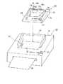
図1に示すように、本発明を適用したプリントシステム1は、図1に示すように、ディジタルスチルカメラ10と、このディジタルスチルカメラ10が装着されるスタンド装置20と、このスタンド装置20が装着されるプリンタ装置30とを備える。 As shown in FIG. 1, a printing system 1 to which the present invention is applied includes a
このディジタルスチルカメラ10は、図1及び図2に示すように、略矩形をなすカメラ本体部11を有する。このカメラ本体部11には、カメラ機能を実現する種々の電気回路が組み込まれた制御回路基板が内蔵されていると共に、充電型電池であるバッテリが配設されている。このカメラ本体部11には、前面部に、複数のレンズやCCD(Charge-Coupled Devices)素子、CMOS(Complementary Metal-Oxide Semiconductor))等の撮像素子で構成された撮像部12が設けられ、上面に、シャッタ釦18が設けられている。また、カメラ本体部11には、背面部に、表示部13が設けられている。この表示部13は、例えば略矩形をなし、LCD(Liquid Crystal Display)や有機ELディスプレイ(Organic Electroluminescence Display)等の表示素子で形成されている。この表示部13の上側には、撮影範囲を見定めるファインダ部14が設けられている。また、この表示部13に隣り合うようにして、カメラ本体部11の背面部には、複数の操作釦でなる操作部15が設けられている。この操作部15は、例えば、内部メモリに保存格納されている画像データを表示部13に表示させる操作を行うことができる。また、操作部15では、ディジタルスチルカメラ10の詳細な設定、例えばフラッシュのオンオフ等を設定することができる。As shown in FIGS. 1 and 2, the digital
更に、カメラ本体部11の底面部には、三脚等が取り付けられる取付孔16が設けられている。この取付孔16は、三脚等のアクセサリが取り付けられると共に、スタンド装置20に装着されたとき、スタンド装置20のカメラ装着部に形成された位置決め突起が係合する孔となる。更に、カメラ本体部11の底面部には、スタンド装置20と電気的接続をするためのジャック部17が設けられている。このジャック部17からは、充電用の電源が供給され、また、カメラ本体部11のメモリに格納されている画像データをスタンド装置20側に出力することができる。 Furthermore, a
以上のように構成されたディジタルスチルカメラ10は、表示部13で撮像部12が現在写している画像を見ながら、シャッタ釦18を押して写真をとることができる。このディジタルスチルカメラ10は、撮像した画像データを、内部メモリに格納し保存することができる。また、ディジタルスチルカメラ10は、操作部15を操作することによって、メモリに格納されている画像データを表示部13で再生することもできる。なお、このメモリは、カメラ本体部11に内蔵されたメモリであっても良く、また、カメラ本体部11に対して着脱可能であっても良い。また、ディジタルスチルカメラ10は、撮影時には、ユーザに把持されて使用され、また、非使用時にはスタンド装置20に設置される。また、ディジタルスチルカメラ10は、スタンド装置20に装着した状態でメモリに保存されている画像データを再生し、表示部13で再生した画像を見ることができる。Or digital
以上のようなディジタルスチルカメラ10が装着されるスタンド装置20は、図1乃至図3に示すように、全体が略矩形をなすスタンド本体部21を有する。このスタンド本体部21は、その上面で背面側に偏った位置に、ディジタルスチルカメラ10の底面部の外形形状に対応したカメラ装着部22が形成されている。このカメラ装着部22は、ディジタルスチルカメラ10の底面部の形状に対応した凹部で構成されている。 As shown in FIGS. 1 to 3, the
このカメラ装着部22の底面部23は、スタンド本体部21の背面部から前面部に向かって上側に傾斜して形成されている。したがって、図1に示すように、ディジタルスチルカメラ10は、スタンド装置20のカメラ装着部22に装着されたとき、カメラ本体部11の背面部に設けられた表示部13がスタンド装置20の前面部を向き、表示部13に表示された画像を見やすくすることができる。また、このカメラ装着部22には、カメラ本体部11の底面部に設けられたジャック部17に接続されるコネクタ24が設けられている。このコネクタ24は、ディジタルスチルカメラ10のジャック部17と電気的に接続されることによって、ディジタルスチルカメラ10に充電用の電源を供給すると共に、画像データがディジタルスチルカメラ10から入力される。また、操作部27でのディジタルスチルカメラ10を操作するための操作信号をディジタルスチルカメラ10に入力する。また、底面部23には、カメラ本体部11の底面部に形成された取付孔16に係合する位置決め突起25が形成されている。 The
以上のようなカメラ装着部22には、スタンド本体部31の背面側に、カメラ本体部11の前面側を支持する支持片26がカメラ本体部11の前面部と前面部に隣り合う両側面部に当接するように略コ字状をなして形成されている。この支持片26は、カメラ装着部22に表示部13が上を向くように斜めに装着されたカメラ本体部11を底面部側から支持する。 In the
スタンド本体部21は、カメラ装着部22の前面側が操作面とされ、この操作面には、複数の押し釦で構成された操作部27が設けられている。操作部27は、ディジタルスチルカメラ10がカメラ装着部22に装着され電気的接続が図られたとき、操作部15と略同様な操作を行うことができる。 The
スタンド本体部21には、背面部に、ディスプレイ等と接続され画像データ等のAVデータを出力する接続コードが接続される第1のジャック部28aやパーソナルコンピュータ等の情報処理装置に接続され画像データ等を出力する接続コードが接続される第2のジャック部28bや直流電源が入力される第3のジャック部28cが設けられている。なお、スタンド本体部21の背面部には、ジャック部の他に、入出力を切り換える切換スイッチ等を設けるようにしても良い。また、スタンド本体部21の底面部には、プリンタ装置30とスタンド装着部と電気的接続を行うためのジャック部29が設けられている。 The stand
なお、スタンド本体部21の内部には、プリント配線基板が内蔵され、このプリント配線基板には、ディジタルスチルカメラ10とプリンタ装置30との中継をするための回路やディジタルスチルカメラ10のバッテリを充電するための充電制御回路等が組み込まれている。 A printed wiring board is built in the stand
以上のようなスタンド装置20のカメラ装着部22には、ディジタルスチルカメラ10の表示部13が設けられた背面部を前面側にし、撮像部12を背面側にして、ディジタルスチルカメラ10が装着されることになる。このカメラ装着部22は、スタンド本体部21の背面側に略コ字状をなすように設けられた支持片26によってディジタルスチルカメラ10の前面側を支持する。ディジタルスチルカメラ10がカメラ装着部22に装着された状態においては、カメラ装着部22に設けられたコネクタ24とカメラ本体部11の底面部に設けられたジャック部17とが電気的に接続される。ディジタルスチルカメラ10は、スタンド装置20に装着された状態において、例えば第3のジャック部28bから入力されるDC電源によってバッテリに充電を行うことができる。また、ディジタルスチルカメラ10は、スタンド装置20に装着された状態において、カメラ本体部11に内蔵されたメモリに格納された画像データを、表示部13に表示することができる他、更に、第2のジャック部28bに接続された接続コードによって接続されたモニタに表示させることができる。このようなスタンド装置20に装着されているディジタルスチルカメラ10の操作は、ディジタルスチルカメラ10の操作部15の他、スタンド装置20の操作部27を用いて行うことができる。 The
なお、このカメラ装着部22は、スタンド装置20の前面側に、ディジタルスチルカメラ10を支持する支持片が設けられていない。したがって、ディジタルスチルカメラ10の取り外しは、スタンド装置20の前面側に傾倒させるようにして行われる。 The
以上のように、ディジタルスチルカメラ10のメモリに格納されている画像データの再生や印刷を行うときには、スタンド装置20に装着された状態で行われることが多い。そこで、更に、プリントシステム1では、スタンド装置20をプリンタ装置30に装着し、ディジタルスチルカメラ10のメモリに格納されている画像データをプリンタ装置30に出力し、プリンタ装置30で画像データを印刷することができるようにしている。 As described above, when image data stored in the memory of the digital
スタンド装置20が装着されるプリンタ装置30は、図1及び図3に示すように、筐体31の上面にスタンド装置20が装着されるスタンド装着部32が設けられている。このスタンド装着部32は、スタンド装置20の底面部の形状に対応した凹部で構成されている。このスタンド装着部32の底面部には、スタンド装置20を構成するスタンド本体部21の底面部に設けられたジャック部29に接続されるコネクタ33が設けられている。このコネクタ33は、スタンド装置20にディジタルスチルカメラ10が装着されているとき、スタンド装置20を介してディジタルスチルカメラ10の充電用の電源を供給すると共に、スタンド装置20を介してディジタルスチルカメラ10から画像データが入力される。また、操作部でのディジタルスチルカメラ10を操作するための操作信号をディジタルスチルカメラ10に入力する。 As shown in FIGS. 1 and 3, the
このカメラ装着部22には、スタンド装置20の前面部を筐体31の前面側にしてスタンド装置20が装着される。ところで、上述したスタンド装置20のスタンド本体部21には、背面部に、第1乃至第3のジャック部28a〜28cが設けられている。そこで、スタンド装着部32の背面側には、スタンド装着部32に装着されたスタンド本体部21の背面部を多く覆い片34が設けられている。覆い片34は、図4に示すように、少なくともスタンド本体部21の背面部の第1乃至第3のジャック部28a〜28cを覆うことができる大きさに形成され、スタンド装着部32にスタンド装置20が装着された状態において、第1乃至第3のジャック部28a〜28cを隠し、見栄えを良くすると共に、第1乃至第3のジャック部28a〜28cへの塵埃等の付着を防止する。 The
この覆い片34は、スタンド装置20をスタンド装着部32に装着するに当たっての位置規制壁としても機能させるため、ここでは、スタンド本体部21の背面部の他、この背面部と隣り合う両側面部を覆うように、略コ字状をなすように形成されている。 Since this
プリンタ装置30を構成する筐体31の上面であってスタンド装着部32の前面側には、複数の押し釦で構成された操作部35が設けられている。操作部35は、スタンド装置20がスタンド装着部32に装着され電気的接続が図られたとき、ディジタルスチルカメラ10の操作部15やスタンド装置20の操作部27と略同様な操作を行うことができる。 On the upper surface of the
また、このプリンタ装置30には、記録紙36に画像データを印刷する印刷部が設けられている。この印刷部は、印刷を行う記録ヘッド、記録紙36を走行させる走行機構等で構成されている。印刷ヘッドとしては、感熱記録を行うためのサーマルヘッドやインクで印刷を行うインクジェットヘッドやレーザ印刷を行うレーザプリンタヘッドである。印刷ヘッドは、例えば、スタンド装置20を介してディジタルスチルカメラ10から入力された画像データを記録紙36に印刷する。 The
以上のようなプリンタ装置30では、ディジタルスチルカメラ10が装着されたスタンド装置20をスタンド装着部32に装着することができる。このとき、スタンド装置20の背面部に設けられている第1乃至第3のジャック部28a〜28cは、覆い片34より覆われ外部に露出しない。したがって、プリンタ装置30は、スタンド装置20がスタンド装着部32に装着された際に見栄えが悪くなり、また、第1乃至第3のジャック部28a〜28cに塵埃等が付着することを防止することができる。 In the
このプリンタ装置30では、スタンド装着部32に、ディジタルスチルカメラ10が装着されたスタンド装置20が装着されると、スタンド装置20のジャック部29にコネクタ33が電気的に接続されることになり、これにより、ディジタルスチルカメラ10から出力された画像データがスタンド装置20を介して入力されることになり、入力された画像データを印刷できるようになる。また、プリンタ装置30は、ディジタルスチルカメラ10が装着されたスタンド装置20が装着された状態において、ディジタルスチルカメラ10にスタンド装置20を介して充電を行うことができる。 In the
また、このプリンタ装置30では、ディジタルスチルカメラ10が装着されていないスタンド装置20を装着することができる。例えば、スタンド装置20に画像データを保存するメモリ機能がある場合には、このメモリに格納された画像データがプリンタ装置30に入力され、入力された画像データを印刷することができる。 In the
ところで、以上のようにプリントシステム1を構成するディジタルスチルカメラ10、スタンド装置20及びプリンタ装置30は、図5に示すような回路構成を有する。 By the way, the digital
具体的に、上述したディジタルスチルカメラ10は、ディジタルスチルカメラ10の全体の制御を行うカメラ制御部41が設けられている。このカメラ制御部41には、上述した撮像部12、表示部13、操作部15、シャッタ釦18が電気的に接続されている他に、撮像部12が撮像した画像データを保存するメモリ42と、スタンド装置20と電気的に接続されるスタンドインタフェース(以下、単にスタンドI/Fという。)43とが電気的に接続されている。 Specifically, the digital
メモリ42は、カメラ本体部11に内蔵された半導体メモリ、磁気ディスク等やカメラ本体部11に対して着脱可能な半導体メモリを記憶素子に用いるICカード、光ディスク、磁気ディスク等である。メモリ42は、このような記録媒体に、撮像された画像データ等を保存する。 The
スタンドI/F43は、第1のスタンドI/Fで、スタンド装置20とデータ通信等を行うインタフェースであり、カメラ本体11の底面部にあるジャック部17を有している。スタンドI/F43からは、スタンド装置20から各種操作信号がディジタルスチルカメラ10に入力されると共に、メモリ42に格納された画像データやディジタルスチルカメラ10で発生した操作信号が出力される。また、ディジタルスチルカメラ10の充電型電池であるバッテリ44に充電を行うための充電用電源がスタンド装置20から供給される。The stand I /F 43 is afirst stand I / F and is an interface for performing data communication and the like with the
以上のようなディジタルスチルカメラ10では、操作部15を用いてカメラモードと再生モードを選択することができる。カメラモードのときには、撮像部12で撮像した画像データ等をメモリ42に保存することができ、再生モードのときには、メモリ42に格納されている画像データを、表示部13やスタンド装置20の第1のジャック部28aに接続されたモニタ等に出力することで、メモリ42に格納された画像データを見ることができるようにする。また、ディジタルスチルカメラ10は、スタンド装置20に装着されているとき、バッテリ44に対して充電を行うことができる。In the digital
また、スタンド装置20は、スタンド装置20の全体の制御を行うスタンド制御部51が設けられている。このスタンド制御部51には、上述した操作部27、第1乃至第3のジャック部28a〜28cが接続される他に、画像データ等を格納するメモリ52、ディジタルスチルカメラ10のバッテリ44を充電するための充電回路となる充電制御部53、ディジタルスチルカメラ10のスタンドI/F43と接続されるカメラI/F(以下、単にカメラI/Fという。)54、プリンタ装置30と電気的に接続されるプリンタインタフェース(以下、単にプリンタI/Fという。)55が電気的に接続されている。The
メモリ52は、スタンド本体部21に内蔵された半導体メモリ、磁気ディスク等やカメラ本体部11に対して着脱可能な半導体メモリを記憶素子に用いるICカード、光ディスク、磁気ディスク等である。メモリ52は、このような記録媒体に、ディジタルスチルカメラ10から送信された画像データやその他の電子機器から第2のジャック部28bから入力された画像データを蓄積する。なお、メモリ52には、更に、無線で受信した画像データを格納するようにしても良い。 The
充電制御部53は、第3のジャック部28cやプリンタ装置30から入力された直流電源をディジタルスチルカメラ10のバッテリ44の充電用としてカメラインタフェース54を介してディジタルスチルカメラ10に供給する。これにより、スタンド装置20は、ディジタルスチルカメラ10が装着されているときにバッテリ44に充電を行うことができるようになる。The charging control unit 53 supplies the DC power input from the
カメラI/F54は、ディジタルスチルカメラ10とデータ通信等を行うインタフェースであり、コネクタ24が接続されている。カメラI/F54からは、ディジタルスチルカメラ10からの各種操作信号や画像データが入力されると共に、ディジタルスチルカメラ10のバッテリ44に充電を行うための充電用電源を供給する。The camera I /
プリンタI/F55は、プリンタ装置30とデータ通信等を行うインタフェースであり、ジャック部29が設けられている。プリンタI/F55からは、印刷用の画像データ等がプリンタ装置30に出力され、また、ディジタルスチルカメラ10のバッテリ44に充電を行うための充電用電源が供給される。The printer I /
以上のようなスタンド装置20では、ディジタルスチルカメラ10が装着されているとき、ディジタルスチルカメラ10のバッテリ44に対して第3のジャック部28c又はプリンタ装置30から入力された直流電源を、結合されたスタンドI/F43及びカメラI/F54を介して供給し、充電を行うことができる。また、スタンド装置20は、メモリ52に、ディジタルスチルカメラ10からカメラI/F54から入力された画像データや第2のジャック部28bから入力された画像データをメモリ52に格納することができる。したがって、このスタンド装置20は、ディジタルスチルカメラ10が装着されている他、ディジタルスチルカメラ10が装着されていない状態であっても、メモリ52に格納された画像データを印刷用としてプリンタI/F55から出力することができる。In the
また、プリンタ装置30は、プリンタ装置30の全体の制御を行うプリンタ制御部61が設けられている。このプリンタ制御部61は、印刷を行う印刷部62、操作部35が電気的に接続されていると共に、スタンド装置20のプリンタI/F55と接続されるスタンドI/F63や他の電子機器、例えばパーソナルコンピュータと接続するための通信インタフェース(以下、通信I/Fともいう。)64が電気的に接続されている。 Further, the
印刷部62は、印刷を行う記録ヘッド、記録紙36を走行させる走行機構等で構成されている。印刷ヘッド62としては、感熱記録を行うためのサーマルヘッドやインクで印刷を行うインクジェットヘッドやレーザ印刷を行うレーザプリンタヘッドである。印刷ヘッド62は、例えば、スタンド装置20を介してディジタルスチルカメラ10から入力された画像データを記録紙36に印刷する。 The
スタンドI/F63は、第2のスタンドI/Fで、スタンド装置20とデータ通信等を行うインタフェースであり、コネクタ33を有している。スタンドI/F63には、印刷用の画像データ等がプリンタ装置30に入力される。また、スタンドI/F63は、ディジタルスチルカメラ10のバッテリ44に充電を行うための充電用電源をスタンド装置20を介してディジタルスチルカメラ10に供給する。Stand I /
通信I/F64は、パーソナルコンピュータ等の他の電子機器とデータ通信を有線又は無線で行うインタフェースであり、例えば、他の電子機器から送信された画像データを受信する。 The communication I /
以上のようなプリンタ装置30では、ディジタルスチルカメラ10のメモリ42からスタンド装置20を介して入力された画像データやスタンド装置20のメモリ52から入力された画像データを受信すると、この受信した画像データを印刷部62で印刷することができる。また、このプリンタ装置30では、ディジタルスチルカメラ10が装着されたスタンド装置20が装着されることによって、スタンド装置20を介してディジタルスチルカメラ10に充電用電源を供給することができる。 In the
以上のようなプリントシステム1では、ディジタルスチルカメラ10をスタンド装置20に装着することができるようにし、更に、スタンド装置20をプリンタ装置30に装着するようにし、相互に電気的に接続するようにしている。したがって、プリンタ装置30のスタンド装着部32の形状等のインタフェースを共通化すれば、様々なディジタルスチルカメラ10をプリンタ装置30に電気的に接続することができる。そして、プリンタ装置30にスタンド装置20を装着するに当たって、プリンタ装置30のスタンド装着部32には、覆い片34が設けられ、スタンド装置20の背面部に設けられた第1乃至第3のジャック部28a〜28cを覆うようにしていることから、スタンド装置20がプリンタ装置30に装着された際の見栄えが悪くなることを防止することができる。 In the print system 1 as described above, the digital
なお、スタンド装置20がプリンタ装置30のスタンド装着部32に装着されると、第1乃至第3のジャック部28a〜28cは、覆い片34に覆われ、使用不能となるが、スタンド装置20とプリンタ装置30とは、電気的に接続されていることで、プリンタ装置30のインタフェースで第1乃至第3のジャック部28a〜28cの代用をすることができる。 When the
また、スタンド装置20には、ディジタルスチルカメラ10が背面部の表示部13を前面側にして装着され、更に、スタンド装置30がディジタルスチルカメラ10の表示部13をプリンタ装置30の前面側にして装着されることになる。したがって、ユーザは、ディジタルスチルカメラ10の操作部15やスタンド装置20の操作部27やプリンタ装置30の操作部35を用いて、ディジタルスチルカメラ10の表示部13に表示された画像を見ながら印刷する画像データを容易に選択することができる。 In addition, the digital
そして、プリントシステム1では、ディジタルスチルカメラ10はスタンド装置20を介してプリンタ装置30に電気的に接続され、ディジタルスチルカメラ10が装着されていなくてもスタンド装置20のみをプリンタ装置30と電気的に接続することができ、ディジタルスチルカメラ10のメモリ42に格納された画像データやスタンド装置20のメモリ52に格納された画像データをプリンタ装置30で印刷することができ、利便性の向上を図ることができる。 In the printing system 1, the digital
また、ディジタルスチルカメラ10をスタンド装置20に装着し、このスタンド装置20をプリンタ装置30に装着しているとき、ディジタルスチルカメラ10の充電を行うことができることから、利便性の向上を図ることができる。 Further, since the digital
なお、スタンド装置に装着される装置は、上述したディジタルスチルカメラ10に限定されるものではなく、その他ビデオカメラ等撮像機能を有する電気機器であれば特に限定されるものではない。また、ディジタルスチルカメラ10とスタンド装置20の電気的接続及び/又はスタンド装置20とプリンタ装置30の電気的接続は、コネクタとジャックを用いる他、装着部に装着されたとき、端子同士が接触する接点で行うようにしてもよい。 The device mounted on the stand device is not limited to the digital
10 ディジタルスチルカメラ、11 カメラ本体部、12 撮像部、13 表示部、15 操作部、17 ジャック部、20 スタンド装置、21 スタンド本体部、22 カメラ装着部。23 底面部、24 コネクタ、25 位置決め突起、26 支持片、27 操作部、28a〜28c 第1乃至第3のジャック部、29 ジャック部、30 プリンタ装置、31 筐体、32 スタンド装着部、33 コネクタ、34 覆い片、35 操作部DESCRIPTION OF
Claims (2)
Translated fromJapanese上記カメラ装置が電気的に接続された状態で装着されるカメラ装着部と、背面部に設けられ他の電子機器と電気的に接続される端子部又は操作部と、上記カメラ装着部に設けられ上記カメラ装置の第1のスタンドI/Fと電気的に接続されるカメラI/Fと、底面部に設けられるプリンタI/Fと、上記カメラ装置の充電型電池の充電を行う充電制御部とを有するスタンド装置と、
上記スタンド装置の底面部の形状に対応した凹部で構成され上記スタンド装置が電気的に接続された状態で装着される共通化されたスタンド装着部と、該スタンド装着部に設けられ上記スタンド装置のプリンタI/Fと電気的に接続される第2のスタンドI/Fと、上記スタンド装置から入力された画像データを印刷する印刷部とを有するプリンタ装置とを備え、
上記スタンド装着部には、上記スタンド装置の背面部に設けられた端子部又は操作部を含む上記スタンド装置の背面部と該背面部と隣り合う両側面部を覆う覆い片が設けられ、
上記カメラ装置が上記スタンド装置のカメラ装着部に装着され上記第1のスタンドI/Fと上記カメラI/Fとが電気的に接続され、該スタンド装置が上記プリンタ装置に装着され上記プリンタI/Fと第2のスタンドI/Fとが電気的に接続された状態において、上記スタンド装置の充電制御部は、上記プリンタ装置から供給される充電用電源を上記カメラ装置に供給し、上記カメラ装置の充電型電池の充電を行うプリントシステム。A camera device having an imaging unit, a memory for storing image data captured by the imaging unit, a rechargeable battery, and a first stand I / F provided on the bottom surface ;
A camera mounting unit that is mounted in a state where the camera device is electrically connected, a terminal unit or an operation unitthat is provided on the back surface and is electrically connectedto another electronic device, andis provided in the camera mounting unit. A camera I / F electrically connected to the first stand I / F of the camera device; a printer I / F provided on the bottom surface; a charge control unit for charging a rechargeable battery of the camera device; A stand device comprising:
Acommon stand mounting portionconfigured with a recess corresponding to the shape of the bottom surface portion of the stand device and mounted in a state where the stand device is electrically connected, and the stand device provided on the stand mounting portion. A printer device having a second stand I / F electrically connected to the printer I / F, and aprinting unit for printing image data input from the stand device;
The stand mounting portion is provided with a covering piece that coversa back surface portion of the stand device including a terminal portion or an operation portion provided on a back surface portion of thestand device and both side surface portions adjacent to the back surface portion,
The camera device is mounted on a camera mounting portion of the stand device, the first stand I / F and the camera I / F are electrically connected, and the stand device is mounted on the printer device and the printer I / F. In a state where F and the second stand I / F are electrically connected, the charging control unit of the stand device supplies the camera device with the charging power supplied from the printer device, and the camera device. Printing systemthat charges a rechargeable battery .
Priority Applications (4)
| Application Number | Priority Date | Filing Date | Title |
|---|---|---|---|
| JP2004368317AJP4396511B2 (en) | 2004-12-20 | 2004-12-20 | Printing system |
| US11/300,312US8045050B2 (en) | 2004-12-20 | 2005-12-15 | Printing system having a cradle mounted to a printer and a camera mounted to the cradle |
| KR1020050124798AKR101173891B1 (en) | 2004-12-20 | 2005-12-16 | Printing system |
| CNB2005101377114ACN100512406C (en) | 2004-12-20 | 2005-12-20 | Printing system |
Applications Claiming Priority (1)
| Application Number | Priority Date | Filing Date | Title |
|---|---|---|---|
| JP2004368317AJP4396511B2 (en) | 2004-12-20 | 2004-12-20 | Printing system |
Publications (2)
| Publication Number | Publication Date |
|---|---|
| JP2006175607A JP2006175607A (en) | 2006-07-06 |
| JP4396511B2true JP4396511B2 (en) | 2010-01-13 |
Family
ID=36595156
Family Applications (1)
| Application Number | Title | Priority Date | Filing Date |
|---|---|---|---|
| JP2004368317AExpired - Fee RelatedJP4396511B2 (en) | 2004-12-20 | 2004-12-20 | Printing system |
Country Status (4)
| Country | Link |
|---|---|
| US (1) | US8045050B2 (en) |
| JP (1) | JP4396511B2 (en) |
| KR (1) | KR101173891B1 (en) |
| CN (1) | CN100512406C (en) |
Families Citing this family (10)
| Publication number | Priority date | Publication date | Assignee | Title |
|---|---|---|---|---|
| JP4936504B2 (en)* | 2005-09-26 | 2012-05-23 | キヤノン株式会社 | Cradle device and operation terminal program thereof, and camera system |
| US7697827B2 (en) | 2005-10-17 | 2010-04-13 | Konicek Jeffrey C | User-friendlier interfaces for a camera |
| USD558260S1 (en)* | 2005-10-27 | 2007-12-25 | Hewlett-Packard Development Company, L.P. | Printer |
| JP2009048309A (en)* | 2007-08-15 | 2009-03-05 | Hoya Corp | Portable equipment |
| CN102758993B (en)* | 2011-04-26 | 2015-12-16 | 富泰华工业(深圳)有限公司 | Base and use the electronic equipment of this base |
| US20120320226A1 (en)* | 2011-06-14 | 2012-12-20 | Chee Meng Chen | Stationary printing apparatus with camera |
| JP2016028879A (en)* | 2014-07-14 | 2016-03-03 | セイコーエプソン株式会社 | Charging device and charging system |
| US9623690B2 (en)* | 2015-02-16 | 2017-04-18 | Zih Corp. | Cradle apparatus and printing device interface |
| JP6537856B2 (en)* | 2015-03-13 | 2019-07-03 | 富士通コンポーネント株式会社 | Electronic device, power supply device and electronic device system |
| USD847138S1 (en)* | 2017-10-03 | 2019-04-30 | C & A Marketing, Inc. | Film scanner |
Family Cites Families (17)
| Publication number | Priority date | Publication date | Assignee | Title |
|---|---|---|---|---|
| US5498949A (en)* | 1993-08-16 | 1996-03-12 | Eastman Kodak Company | Rechargeable device with operational inhibit during recharging |
| US7212229B2 (en)* | 1997-04-04 | 2007-05-01 | Eastman Kodak Company | Digital camera providing image processing for an attachable printer |
| JP4536172B2 (en)* | 1998-07-17 | 2010-09-01 | ソニー株式会社 | Connection base, printer and photographing device |
| AUPP702198A0 (en)* | 1998-11-09 | 1998-12-03 | Silverbrook Research Pty Ltd | Image creation method and apparatus (ART79) |
| US6721001B1 (en)* | 1998-12-16 | 2004-04-13 | International Business Machines Corporation | Digital camera with voice recognition annotation |
| US20030156200A1 (en)* | 2000-05-16 | 2003-08-21 | Eastman Kodak Company | Printing system and method having a docking digital printer that uses a digital camera image display |
| US20020071035A1 (en)* | 2000-12-07 | 2002-06-13 | Sobol Robert E. | Digital camera docking station |
| JP2002374447A (en) | 2001-04-12 | 2002-12-26 | Fuji Photo Film Co Ltd | Cradle for information equipment, cradle for digital camera, and camera system |
| JP4192441B2 (en) | 2001-05-28 | 2008-12-10 | 富士フイルム株式会社 | Camera cradle equipment |
| US7075579B2 (en)* | 2001-06-05 | 2006-07-11 | Eastman Kodak Company | Docking station assembly for transmitting digital files |
| US7196810B2 (en)* | 2001-08-28 | 2007-03-27 | Casio Computer Co., Ltd | Printing system |
| US7170557B2 (en)* | 2002-03-26 | 2007-01-30 | Eastman Kodak Company | Modular digital imaging system |
| JP3884330B2 (en)* | 2002-06-07 | 2007-02-21 | オリンパス株式会社 | Image printing system |
| JP2004088729A (en)* | 2002-06-25 | 2004-03-18 | Fuji Photo Film Co Ltd | Digital camera system |
| JP4338170B2 (en) | 2002-09-30 | 2009-10-07 | キヤノン株式会社 | Image forming apparatus |
| US7312817B2 (en)* | 2003-04-22 | 2007-12-25 | Hewlett-Packard Development Company, L.P. | Printer and docking station having a digital camera docking port with an image magnifier |
| US7411608B1 (en)* | 2004-08-20 | 2008-08-12 | Raymond Wayne Moskaluk | System and method for producing photographic prints |
- 2004
- 2004-12-20JPJP2004368317Apatent/JP4396511B2/ennot_activeExpired - Fee Related
- 2005
- 2005-12-15USUS11/300,312patent/US8045050B2/ennot_activeExpired - Fee Related
- 2005-12-16KRKR1020050124798Apatent/KR101173891B1/ennot_activeExpired - Fee Related
- 2005-12-20CNCNB2005101377114Apatent/CN100512406C/ennot_activeExpired - Fee Related
Also Published As
| Publication number | Publication date |
|---|---|
| KR101173891B1 (en) | 2012-08-14 |
| CN1794805A (en) | 2006-06-28 |
| US20060132609A1 (en) | 2006-06-22 |
| CN100512406C (en) | 2009-07-08 |
| JP2006175607A (en) | 2006-07-06 |
| KR20060070441A (en) | 2006-06-23 |
| US8045050B2 (en) | 2011-10-25 |
Similar Documents
| Publication | Publication Date | Title |
|---|---|---|
| JP7476289B2 (en) | Imaging device | |
| US7253840B2 (en) | Cradle for digital camera | |
| JP2007310005A (en) | Camera system | |
| JP4396511B2 (en) | Printing system | |
| JP2013207325A (en) | Image pickup device equipped with accessory shoe | |
| JP2007279486A (en) | camera | |
| US11526069B2 (en) | Image capturing apparatus having high operability | |
| JP2005345576A (en) | Imaging device | |
| JP2021117476A (en) | Imaging device | |
| JP5645634B2 (en) | Imaging device | |
| JP2002353640A (en) | Holding apparatus | |
| JP2002359763A (en) | Stand for digital camera | |
| US7437067B2 (en) | Stand apparatus, electronic equipment using the same and its accessory apparatus | |
| JP4380266B2 (en) | Connection device for electronic equipment | |
| JP2012129782A5 (en) | ||
| JP2006237774A (en) | Camera system | |
| JP7571095B2 (en) | Electronics | |
| JPH06205251A (en) | Digital still camera | |
| JP4425483B2 (en) | Electronic equipment system | |
| JP2008148341A (en) | Imaging apparatus | |
| JP2024155362A (en) | Electronics | |
| JP2001313858A (en) | Electronic camera | |
| JP2005323261A (en) | Accessory set | |
| JPH11258671A (en) | Housing structure of imaging device and electronic device | |
| JP4129159B2 (en) | Camera accessories |
Legal Events
| Date | Code | Title | Description |
|---|---|---|---|
| A977 | Report on retrieval | Free format text:JAPANESE INTERMEDIATE CODE: A971007 Effective date:20080828 | |
| A131 | Notification of reasons for refusal | Free format text:JAPANESE INTERMEDIATE CODE: A131 Effective date:20090421 | |
| A521 | Request for written amendment filed | Free format text:JAPANESE INTERMEDIATE CODE: A523 Effective date:20090619 | |
| A131 | Notification of reasons for refusal | Free format text:JAPANESE INTERMEDIATE CODE: A131 Effective date:20090714 | |
| A521 | Request for written amendment filed | Free format text:JAPANESE INTERMEDIATE CODE: A523 Effective date:20090902 | |
| TRDD | Decision of grant or rejection written | ||
| A01 | Written decision to grant a patent or to grant a registration (utility model) | Free format text:JAPANESE INTERMEDIATE CODE: A01 Effective date:20090929 | |
| A01 | Written decision to grant a patent or to grant a registration (utility model) | Free format text:JAPANESE INTERMEDIATE CODE: A01 | |
| A61 | First payment of annual fees (during grant procedure) | Free format text:JAPANESE INTERMEDIATE CODE: A61 Effective date:20091012 | |
| FPAY | Renewal fee payment (event date is renewal date of database) | Free format text:PAYMENT UNTIL: 20121030 Year of fee payment:3 | |
| FPAY | Renewal fee payment (event date is renewal date of database) | Free format text:PAYMENT UNTIL: 20131030 Year of fee payment:4 | |
| LAPS | Cancellation because of no payment of annual fees |