JP4395792B2 - projector - Google Patents
projectorDownload PDFInfo
- Publication number
- JP4395792B2 JP4395792B2JP2007017504AJP2007017504AJP4395792B2JP 4395792 B2JP4395792 B2JP 4395792B2JP 2007017504 AJP2007017504 AJP 2007017504AJP 2007017504 AJP2007017504 AJP 2007017504AJP 4395792 B2JP4395792 B2JP 4395792B2
- Authority
- JP
- Japan
- Prior art keywords
- light
- infrared
- light source
- visible
- modulation element
- Prior art date
- Legal status (The legal status is an assumption and is not a legal conclusion. Google has not performed a legal analysis and makes no representation as to the accuracy of the status listed.)
- Expired - Fee Related
Links
- 239000004973liquid crystal related substanceSubstances0.000claimsdescription97
- 230000003287optical effectEffects0.000claimsdescription47
- 238000000926separation methodMethods0.000claimsdescription33
- 229910052751metalInorganic materials0.000claimsdescription7
- 239000002184metalSubstances0.000claimsdescription7
- 239000003550markerSubstances0.000claimsdescription4
- 238000010586diagramMethods0.000description27
- 230000003595spectral effectEffects0.000description24
- 230000000694effectsEffects0.000description13
- 230000010287polarizationEffects0.000description12
- 238000003384imaging methodMethods0.000description8
- 238000005286illuminationMethods0.000description7
- 230000004075alterationEffects0.000description6
- 239000011521glassSubstances0.000description6
- 230000035945sensitivityEffects0.000description6
- 238000001514detection methodMethods0.000description5
- 239000000463materialSubstances0.000description5
- 230000004044responseEffects0.000description5
- 229910052724xenonInorganic materials0.000description5
- FHNFHKCVQCLJFQ-UHFFFAOYSA-Nxenon atomChemical compound[Xe]FHNFHKCVQCLJFQ-UHFFFAOYSA-N0.000description5
- 238000000034methodMethods0.000description4
- 239000007787solidSubstances0.000description4
- 208000016169Fish-eye diseaseDiseases0.000description3
- 241000282412HomoSpecies0.000description3
- 230000005540biological transmissionEffects0.000description3
- 239000000470constituentSubstances0.000description3
- 230000006870functionEffects0.000description3
- 229910052736halogenInorganic materials0.000description3
- 150000002367halogensChemical class0.000description3
- 241000282414Homo sapiensSpecies0.000description2
- 230000002547anomalous effectEffects0.000description2
- 230000008901benefitEffects0.000description2
- 230000015572biosynthetic processEffects0.000description2
- 238000006243chemical reactionMethods0.000description2
- 239000003086colorantSubstances0.000description2
- 239000006185dispersionSubstances0.000description2
- 230000031700light absorptionEffects0.000description2
- 239000002609mediumSubstances0.000description2
- QSHDDOUJBYECFT-UHFFFAOYSA-NmercuryChemical compound[Hg]QSHDDOUJBYECFT-UHFFFAOYSA-N0.000description2
- 229910052753mercuryInorganic materials0.000description2
- 229910001507metal halideInorganic materials0.000description2
- 150000005309metal halidesChemical class0.000description2
- 239000002923metal particleSubstances0.000description2
- 230000000007visual effectEffects0.000description2
- 208000008918voyeurismDiseases0.000description2
- 230000008859changeEffects0.000description1
- 230000001419dependent effectEffects0.000description1
- 230000006866deteriorationEffects0.000description1
- 239000002612dispersion mediumSubstances0.000description1
- 238000005516engineering processMethods0.000description1
- 230000020169heat generationEffects0.000description1
- 238000012986modificationMethods0.000description1
- 230000004048modificationEffects0.000description1
- 230000002093peripheral effectEffects0.000description1
- 230000029553photosynthesisEffects0.000description1
- 238000010672photosynthesisMethods0.000description1
- 239000000088plastic resinSubstances0.000description1
- 230000002265preventionEffects0.000description1
- 238000003786synthesis reactionMethods0.000description1
- 239000012780transparent materialSubstances0.000description1
Images


Classifications
- G—PHYSICS
- G03—PHOTOGRAPHY; CINEMATOGRAPHY; ANALOGOUS TECHNIQUES USING WAVES OTHER THAN OPTICAL WAVES; ELECTROGRAPHY; HOLOGRAPHY
- G03B—APPARATUS OR ARRANGEMENTS FOR TAKING PHOTOGRAPHS OR FOR PROJECTING OR VIEWING THEM; APPARATUS OR ARRANGEMENTS EMPLOYING ANALOGOUS TECHNIQUES USING WAVES OTHER THAN OPTICAL WAVES; ACCESSORIES THEREFOR
- G03B21/00—Projectors or projection-type viewers; Accessories therefor
- G03B21/14—Details
- G—PHYSICS
- G02—OPTICS
- G02B—OPTICAL ELEMENTS, SYSTEMS OR APPARATUS
- G02B26/00—Optical devices or arrangements for the control of light using movable or deformable optical elements
- G02B26/007—Optical devices or arrangements for the control of light using movable or deformable optical elements the movable or deformable optical element controlling the colour, i.e. a spectral characteristic, of the light
- G02B26/008—Optical devices or arrangements for the control of light using movable or deformable optical elements the movable or deformable optical element controlling the colour, i.e. a spectral characteristic, of the light in the form of devices for effecting sequential colour changes, e.g. colour wheels
- G—PHYSICS
- G02—OPTICS
- G02B—OPTICAL ELEMENTS, SYSTEMS OR APPARATUS
- G02B27/00—Optical systems or apparatus not provided for by any of the groups G02B1/00 - G02B26/00, G02B30/00
- G02B27/10—Beam splitting or combining systems
- G02B27/1006—Beam splitting or combining systems for splitting or combining different wavelengths
- G—PHYSICS
- G02—OPTICS
- G02B—OPTICAL ELEMENTS, SYSTEMS OR APPARATUS
- G02B27/00—Optical systems or apparatus not provided for by any of the groups G02B1/00 - G02B26/00, G02B30/00
- G02B27/10—Beam splitting or combining systems
- G02B27/14—Beam splitting or combining systems operating by reflection only
- G02B27/141—Beam splitting or combining systems operating by reflection only using dichroic mirrors
- G—PHYSICS
- G03—PHOTOGRAPHY; CINEMATOGRAPHY; ANALOGOUS TECHNIQUES USING WAVES OTHER THAN OPTICAL WAVES; ELECTROGRAPHY; HOLOGRAPHY
- G03B—APPARATUS OR ARRANGEMENTS FOR TAKING PHOTOGRAPHS OR FOR PROJECTING OR VIEWING THEM; APPARATUS OR ARRANGEMENTS EMPLOYING ANALOGOUS TECHNIQUES USING WAVES OTHER THAN OPTICAL WAVES; ACCESSORIES THEREFOR
- G03B21/00—Projectors or projection-type viewers; Accessories therefor
- G03B21/005—Projectors using an electronic spatial light modulator but not peculiar thereto
- G—PHYSICS
- G03—PHOTOGRAPHY; CINEMATOGRAPHY; ANALOGOUS TECHNIQUES USING WAVES OTHER THAN OPTICAL WAVES; ELECTROGRAPHY; HOLOGRAPHY
- G03B—APPARATUS OR ARRANGEMENTS FOR TAKING PHOTOGRAPHS OR FOR PROJECTING OR VIEWING THEM; APPARATUS OR ARRANGEMENTS EMPLOYING ANALOGOUS TECHNIQUES USING WAVES OTHER THAN OPTICAL WAVES; ACCESSORIES THEREFOR
- G03B33/00—Colour photography, other than mere exposure or projection of a colour film
- G03B33/08—Sequential recording or projection
Landscapes
- Physics & Mathematics (AREA)
- General Physics & Mathematics (AREA)
- Optics & Photonics (AREA)
- Astronomy & Astrophysics (AREA)
- Spectroscopy & Molecular Physics (AREA)
- Projection Apparatus (AREA)
- Liquid Crystal (AREA)
- Mechanical Light Control Or Optical Switches (AREA)
- Transforming Electric Information Into Light Information (AREA)
Description
Translated fromJapanese本発明は、プロジェクタに関し、可視画像と赤外画像とを一つのスクリーンに表示可能なプロジェクタに関するものである。 The present invention relates to a projector, and more particularly to a projector capable of displaying a visible image and an infrared image on a single screen.
光変調素子に形成された画像情報である光学像をスクリーンに拡大表示するプロジェクタは、コンピュータ等のデジタル機器との整合性が良いことから、主にプレゼンテーション用途、インフォメーション用途、映像鑑賞用途等で広く普及してきている。プロジェクタを含む一般的な表示装置の主たる機能は、人に対して何らかの有意な情報を伝えることである。そのため、表示される画像情報は人が視認できる可視画像として表示されるのが通常である。したがって、一般的なプロジェクタでは光源から放射される光から可視光を選別し、その可視光を照明光として用いて画像表示を行っている。 A projector that enlarges and displays an optical image, which is image information formed on a light modulation element, on a screen has good compatibility with a digital device such as a computer, so it is widely used mainly for presentations, information, and video viewing. It has become widespread. The main function of a general display device including a projector is to convey some significant information to a person. Therefore, the displayed image information is usually displayed as a visible image that can be visually recognized by a person. Therefore, a general projector sorts visible light from light emitted from a light source, and performs image display using the visible light as illumination light.
ところで、プレゼンテーション用途やインフォメーション用途で有意な情報を表示する場合、視認性、可読性、情報の受容性等の観点から表示に適した情報量が存在すると言われている。一度に過度の情報が表示された場合には、看板が多い都会の繁華街では必要な情報を見つけにくいように、人はそれらの情報を的確に把握できなくなるばかりでなく、個々の情報に注意を向けなくなる傾向を有するからである。
また、プレゼンテーション用途や映像鑑賞用途では、表示する情報のセキュリティー性の確保が問題となっている。すなわち、プレゼンテーション情報や映像情報を著作権者に無断で撮影、流用する事態が発生しており、大きな社会問題となりつつある。By the way, when displaying significant information for presentation use or information use, it is said that there is an information amount suitable for display from the viewpoint of visibility, readability, information acceptability, and the like. If too much information is displayed at once, people will not be able to accurately grasp the information so that it is difficult to find the necessary information in the downtown area where there are many signs. It is because it has the tendency to stop directing.
In presentation applications and video appreciation applications, there is a problem of ensuring the security of displayed information. In other words, there is a situation in which presentation information and video information are photographed and used without permission of the copyright holder, which is becoming a major social problem.
そこで、人には視認できない赤外光を用いて表示情報(画像や映像)を制御することが検討されている。赤外光で表示された画像(赤外画像)を人は視認できないが、CCDやCMOSセンサーに代表される撮像素子は赤外域に及ぶ感度を有するため、撮像素子を用いれば表示内容を視認することができる。例えば、非特許文献1(の図1を参照)では、カラーの可視画像を表示する通常の可視光用プロジェクタと赤外光で画像を表示する赤外光用プロジェクタとを組み合わせて用いることによって、表示する情報(画像や映像)を制御する方法が提案されている。具体的には、情報の存在や概略を伝えるような不特定多数の人に見せたい情報は可視画像として表示し、さらに詳しい情報を求める人だけに見て欲しい情報は不可視である赤外画像として表示する。そして、不可視の赤外画像はデジタルカメラ等の撮像素子を用いて見てもらう、という具合である。 Therefore, it has been studied to control display information (images and videos) using infrared light that cannot be seen by humans. An image displayed with infrared light (infrared image) cannot be visually recognized by humans, but an image sensor represented by a CCD or CMOS sensor has sensitivity in the infrared region. be able to. For example, in Non-Patent Document 1 (see FIG. 1), by using a combination of a normal visible light projector that displays a color visible image and an infrared light projector that displays an image with infrared light, A method of controlling information to be displayed (image or video) has been proposed. Specifically, information that you want to show to an unspecified number of people who convey the existence and outline of information is displayed as a visible image, and information that only people who want more detailed information want to see is an invisible infrared image. indicate. Then, the invisible infrared image is viewed using an image sensor such as a digital camera.
また、表示情報のセキュリティー性の確保の観点では、例えば特許文献1では、スクリーンに投写された画像の上に重ねて赤外光用プロジェクタにより赤外画像を投写し、スクリーンに投写された画像をデジタルビデオやデジタルカメラ等の撮像素子によって撮像したときに、撮像した画像中に赤外画像が写し込まれるようにすることで、著作権者に無断での撮影が違法行為であることを知らせて盗撮等を防止しようとする方法が提案されている。
上記の文献に記載されたように、スクリーンに表示する可視画像に不可視の赤外画像を重ねて表示することで表示情報(画像や映像)を制御できたり、盗撮等の不正行為の抑制に有効であるが、本来の情報を投写表示するプロジェクタに加えて、赤外画像を投写する2台目のプロジェクタが必要である。プロジェクタの小型化に伴って可搬型のプロジェクタが増加していることを考慮すると、2台のプロジェクタを用いることは携帯性を阻害するという課題がある。さらに、使用に際してはそれら2台のプロジェクタが投写表示する表示位置を正確に合わせ込む必要がある。プロジェクタを移動するたびに2台のプロジェクタの投写表示位置を正確に合わせ込む作業が必要となり、特に赤外画像は不可視の画像であるため、目視での作業ができないこともあって、設置性や使い勝手が非常に悪くなるという課題がある。 As described in the above document, display information (images and video) can be controlled by overlaying a visible image displayed on the screen with an invisible infrared image, and it is effective in suppressing illegal acts such as voyeurism. However, in addition to a projector that projects and displays original information, a second projector that projects an infrared image is required. Considering that the number of portable projectors has increased with the miniaturization of projectors, the use of two projectors has the problem of hindering portability. Further, when used, it is necessary to accurately match the display positions projected by these two projectors. Each time the projector is moved, it is necessary to accurately align the projection display positions of the two projectors. In particular, since the infrared image is an invisible image, visual operation may not be possible. There is a problem that usability becomes very bad.
本発明は、上記の課題を解決するためになされたものであり、特に1台の装置で、表示画像(画像や映像)の制御を行うためにカラーの可視画像と不可視の赤外画像とを一つの投写面上に重畳して表示することが可能であり、簡便かつ携帯性に優れたプロジェクタを提供することを目的とする。 The present invention has been made in order to solve the above-described problems. In particular, a single device can display a color visible image and an invisible infrared image in order to control a display image (image or video). An object of the present invention is to provide a projector that can be superimposed and displayed on one projection plane and is simple and excellent in portability.
上記の目的を達成するために、本発明の第1のプロジェクタは、可視光と赤外光とを含む光を射出する光源と、前記光源からの光を波長域が異なる一つ以上の可視光と波長域が異なる一つ以上の赤外光とに時間的に分離する光時間分離手段と、前記光時間分離手段によって分離された互いに波長域が異なる複数の光を時間順次に変調する光変調素子と、前記光変調素子によって変調された変調光を被投写面上に投写表示する投写手段と、を備え、前記一つ以上の可視光によって形成される可視画像と前記一つ以上の赤外光によって形成される赤外画像とを含む複数の画像を同一の被投写面上に表示することを特徴とする。 In order to achieve the above object, a first projector according to the present invention includes a light source that emits light including visible light and infrared light, and one or more visible light beams having different wavelength ranges from the light source. Optical time separation means that temporally separates into one or more infrared lights having different wavelength ranges, and optical modulation that sequentially modulates a plurality of lights having different wavelength ranges separated by the optical time separation means And a projection means for projecting and displaying the modulated light modulated by the light modulation element on a projection surface, the visible image formed by the one or more visible lights, and the one or more infrared A plurality of images including an infrared image formed by light are displayed on the same projection surface.
本発明の第2のプロジェクタは、可視光を含む光を射出する第1光源と赤外光を含む光を射出する第2光源とを含む複数の光源と、前記第1光源、前記第2光源のうち、少なくともいずれか一方の光源からの光を波長域が異なる複数の光に時間的に分離する光時間分離手段と、前記第1光源から射出された光と前記第2光源から射出された光とを空間的に一つに合成して合成光とする光源光合成手段と、前記光源光合成手段によって合成された合成光を変調する光変調素子と、前記光変調素子によって変調された変調光を被投写面上に投写表示する投写手段と、を備え、前記可視光を含む光によって形成される可視画像と前記赤外光を含む光によって形成される赤外画像とを含む複数の画像を同一の被投写面上に表示することを特徴とする。 A second projector of the present invention includes a plurality of light sources including a first light source that emits light including visible light and a second light source that emits light including infrared light, the first light source, and the second light source. Among them, light time separation means for temporally separating light from at least one of the light sources into a plurality of lights having different wavelength ranges, light emitted from the first light source, and light emitted from the second light source A light source light combining unit that combines light spatially into a combined light, a light modulation element that modulates the combined light combined by the light source light combining unit, and a modulated light modulated by the light modulation element. A plurality of images including a visible image formed by the light including the visible light and an infrared image formed by the light including the infrared light. It is displayed on the projection surface.
本発明の第3のプロジェクタは、可視光を含む光を射出する第1光源と赤外光を含む光を射出する第2光源とを含み、各光源からの光が時間順次に射出される複数の光源と、前記第1光源および前記第2光源から時間順次に射出された複数の光を時間順次に変調する光変調素子と、前記光変調素子によって変調された変調光を被投写面上に投写表示する投写手段と、を備え、前記可視光を含む光によって形成される可視画像と前記赤外光を含む光によって形成される赤外画像とを含む複数の画像を同一の被投写面上に表示することを特徴とする。 The third projector of the present invention includes a first light source that emits light including visible light and a second light source that emits light including infrared light, and a plurality of light beams emitted from each light source are sequentially emitted. A light source, a light modulation element that time-sequentially modulates a plurality of lights emitted from the first light source and the second light source, and modulated light modulated by the light modulation element on the projection surface A plurality of images including a visible image formed by the light including the visible light and an infrared image formed by the light including the infrared light on the same projection surface. It is characterized by displaying.
本発明の第4のプロジェクタは、可視光と赤外光とを含む光を射出する光源と、前記光源からの光を波長域が異なる一つ以上の可視光と波長域が異なる一つ以上の赤外光とを含む複数の光に時間的に分離する光時間分離手段と、前記光源からの光を波長域が異なる一つ以上の可視光と波長域が異なる一つ以上の赤外光とを含む複数の光に空間的に分離する光空間分離手段と、前記光空間分離手段によって分離された各光の光路毎に設けられ、前記光時間分離手段によって分離された複数の光を時間順次に変調する複数の光変調素子と、前記複数の光変調素子によってそれぞれ変調された複数の変調光を空間的に1つに合成して合成光とする変調光合成手段と、前記変調光合成手段によって合成された合成光を被投写面上に投写表示する投写手段と、を備え、前記一つ以上の可視光によって形成される可視画像と前記一つ以上の赤外光によって形成される赤外画像とを含む複数の画像を同一の被投写面上に表示することを特徴とする。 A fourth projector according to the present invention includes a light source that emits light including visible light and infrared light, and at least one visible light that has a wavelength range different from that of the light source. An optical time separation means for temporally separating a plurality of light including infrared light, and one or more visible lights having different wavelength ranges and one or more infrared lights having different wavelength ranges from the light source. Optical space separation means that spatially separates the light into a plurality of lights, and provided for each light path of each light separated by the light space separation means, and the plurality of lights separated by the light time separation means are sequentially timed. A plurality of light modulating elements to be modulated into a plurality of light, a modulated light combining means that spatially combines a plurality of modulated lights respectively modulated by the plurality of light modulating elements into a combined light, and a combined light by the modulated light combining means Projecting hand that projects and displays the combined light on the projection surface And displaying a plurality of images including a visible image formed by the one or more visible lights and an infrared image formed by the one or more infrared lights on the same projection surface. It is characterized by that.
本発明の第5のプロジェクタは、可視光を含む光を射出する第1光源と赤外光を含む光を射出する第2光源とを含む複数の光源と、前記第1光源、前記第2光源のうち、少なくともいずれか一方の光源からの光を波長域が異なる複数の光に時間的に分離する光時間分離手段と、前記第1光源および前記第2光源からの各光の光路毎に設けられ、前記光時間分離手段によって分離された複数の光を時間順次に変調する複数の光変調素子と、前記複数の光変調素子によって変調された複数の変調光を空間的に1つに合成して合成光とする変調光合成手段と、前記変調光合成手段によって合成された合成光を被投写面上に投写表示する投写手段と、を備え、前記可視光を含む光によって形成される可視画像と前記赤外光を含む光によって形成される赤外画像とを含む複数の画像を同一の被投写面上に表示することを特徴とする。 The fifth projector of the present invention includes a plurality of light sources including a first light source that emits light including visible light and a second light source that emits light including infrared light, the first light source, and the second light source. An optical time separation means for temporally separating light from at least one of the light sources into a plurality of lights having different wavelength ranges, and provided for each optical path of each light from the first light source and the second light source. A plurality of light modulation elements that time-sequentially modulate a plurality of lights separated by the light time separation means, and a plurality of modulated lights modulated by the plurality of light modulation elements are spatially combined into one. Modulated light combining means for combining light, and projection means for projecting and displaying the combined light combined by the modulated light combining means on a projection surface, the visible image formed by the light including the visible light, and Formed by light including infrared light And displaying a plurality of images on the same projection surface onto which includes an outer image.
本発明の第6のプロジェクタは、可視光を含む光を射出する第1光源と赤外光を含む光を射出する第2光源とを含み、各光源からの光が時間順次に射出される複数の光源と、前記第1光源および前記第2光源から時間順次に射出された複数の光のうちの一部の光を時間順次に変調する第1光変調素子と、前記複数の光のうちの残りの光を時間順次に変調する第2光変調素子とを含む複数の光変調素子と、前記複数の光変調素子によって変調された複数の変調光を空間的に1つに合成して合成光とする変調光合成手段と、前記変調光合成手段によって合成された合成光を被投写面上に投写表示する投写手段と、を備え、前記可視光を含む光によって形成される可視画像と前記赤外光を含む光によって形成される赤外画像とを含む複数の画像を同一の被投写面上に表示することを特徴とする。 The sixth projector of the present invention includes a first light source that emits light including visible light and a second light source that emits light including infrared light, and a plurality of light beams emitted from each light source are sequentially emitted. A first light modulation element that time-sequentially modulates a part of the plurality of lights emitted from the first light source and the second light source in a time-sequential manner, and of the plurality of lights A plurality of light modulation elements including a second light modulation element that time-sequentially modulates the remaining light and a plurality of modulated lights modulated by the plurality of light modulation elements are combined into one spatially combined light And a projection means for projecting and displaying the synthesized light synthesized by the modulated light synthesis means on a projection surface, the visible image formed by the light including the visible light and the infrared light Multiple images including infrared images formed by light containing And displaying the on the projection plane.
これら本発明の第1〜第6のプロジェクタの構成によれば、カラーの可視画像と不可視の赤外画像の表示状態を独立に制御できるとともに、両方の画像を一つの被投写面上に正確に位置を合わせた状態で表示することができ、表示情報(画像や映像)の制御が可能となる。また、可視画像と赤外画像の表示を1台のプロジェクタで行えるため、プロジェクタを移動させた場合であっても可視画像と赤外画像の表示位置を合わせ込む作業が必要なく、使い勝手を大幅に向上できる。また、表示システム全体を小型化することができ、携帯性に優れたものとなる。 According to the configurations of the first to sixth projectors of the present invention, the display state of the color visible image and the invisible infrared image can be controlled independently, and both images can be accurately displayed on one projection surface. It is possible to display in a state where the positions are matched, and display information (images and videos) can be controlled. In addition, since a visible image and an infrared image can be displayed with a single projector, there is no need to align the display position of the visible image and the infrared image even when the projector is moved. Can be improved. In addition, the entire display system can be reduced in size and has excellent portability.
上記第1〜第6のプロジェクタは、光源の構成、光変調素子の構成、光時間分離手段の有無等によって分けたものであり、第1のプロジェクタは、可視光と赤外光とを含む光を射出する光源(例えば白色光源)と一つの光変調素子とを備えたものである。第2のプロジェクタは、可視光を含む光を射出する第1光源と赤外光を含む光を射出する第2光源とを含む複数の光源と一つの光変調素子とを用い、光時間分離手段を備えたものである。第3のプロジェクタは、可視光を含む光を射出する第1光源と赤外光を含む光を射出する第2光源とを含み時間順次に点灯する複数の光源と一つの光変調素子とを用い、光時間分離手段を持たないものである。第4のプロジェクタは、可視光と赤外光とを含む光を射出する光源(例えば白色光源)と複数の光変調素子とを備えたものである。第5のプロジェクタは、可視光を含む光を射出する第1光源と赤外光を含む光を射出する第2光源とを含む複数の光源と複数の光変調素子とを用い、光時間分離手段を備えたものである。第6のプロジェクタは、可視光を含む光を射出する第1光源と赤外光を含む光を射出する第2光源とを含み時間順次に点灯する複数の光源と複数の光変調素子とを備え、光時間分離手段を持たないものである。 The first to sixth projectors are divided according to the configuration of the light source, the configuration of the light modulation element, the presence or absence of the light time separation means, and the first projector is a light including visible light and infrared light. A light source that emits light (for example, a white light source) and one light modulation element. The second projector uses a plurality of light sources including a first light source that emits light including visible light and a second light source that emits light including infrared light, and one light modulation element, and uses an optical time separation unit. It is equipped with. The third projector includes a first light source that emits light including visible light and a second light source that emits light including infrared light, and includes a plurality of light sources that are sequentially turned on and a single light modulation element. The optical time separation means is not provided. The fourth projector includes a light source (for example, a white light source) that emits light including visible light and infrared light, and a plurality of light modulation elements. The fifth projector uses a plurality of light sources including a first light source that emits light including visible light and a second light source that emits light including infrared light, and a plurality of light modulation elements, and includes an optical time separation unit. It is equipped with. The sixth projector includes a first light source that emits light including visible light and a second light source that emits light including infrared light, and includes a plurality of light sources that are sequentially turned on and a plurality of light modulation elements. The optical time separation means is not provided.
本発明の第1〜第6のプロジェクタは、複数の光を時間順次に変調する光変調素子、いわゆる時分割駆動の光変調素子を用いる点が共通の特徴である。上記6種のプロジェクタのうち、第1〜第3のプロジェクタにおいては、時分割駆動の光変調素子を一つ用いているため、光学的な構成が簡素になり、コストが低減できるという利点がある。一方、第4〜第6のプロジェクタにおいては、時分割駆動の光変調素子を複数用いており、一つの光変調素子のフレーム周波数を低減できるため、応答速度の遅い光変調素子を用いることができる。また、光源からの赤外光の強度が弱い場合でも、各光変調素子毎のフレーム周波数を低減でき、サブフレームの表示時間を長く取れる。これにより、結果的に赤外光の強度を高められ、撮像素子による撮像、画像検出が容易になる。逆に、フレーム周波数を低減しない場合には、変調可能な赤外光の種類を増やせるため、表示情報の多様な制御が可能となる。また、第2,第3,第5,第6のプロジェクタのように複数の光源を用いた場合には、赤外光の強度を高めやすいという利点がある。 The first to sixth projectors of the present invention have a common feature in that a light modulation element that modulates a plurality of lights in time sequence, that is, a so-called time-division drive light modulation element is used. Among the six types of projectors described above, the first to third projectors have an advantage that the optical configuration is simplified and the cost can be reduced because one time-division driven light modulation element is used. . On the other hand, in the fourth to sixth projectors, a plurality of time-division driven light modulation elements are used, and the frame frequency of one light modulation element can be reduced. Therefore, a light modulation element with a slow response speed can be used. . Even when the intensity of infrared light from the light source is weak, the frame frequency for each light modulation element can be reduced, and the display time of the subframe can be increased. As a result, the intensity of infrared light can be increased as a result, and imaging and image detection by the imaging element are facilitated. On the other hand, when the frame frequency is not reduced, the types of infrared light that can be modulated can be increased, so that various controls of display information are possible. Further, when a plurality of light sources are used like the second, third, fifth, and sixth projectors, there is an advantage that the intensity of infrared light can be easily increased.
また、前記第4〜第6のプロジェクタにおいて、前記複数の光変調素子のうちの一つの光変調素子が前記赤外光を変調する赤外光用光変調素子であり、前記複数の光変調素子のうちの残りの光変調素子が前記可視光を変調する可視光用光変調素子であることが望ましい。
この構成によれば、カラーの可視画像と不可視の赤外画像の表示状態を容易に独立して制御することができる。In the fourth to sixth projectors, one of the plurality of light modulation elements is an infrared light modulation element that modulates the infrared light, and the plurality of light modulation elements It is desirable that the remaining light modulation element is a visible light modulation element that modulates the visible light.
According to this configuration, the display state of the color visible image and the invisible infrared image can be easily and independently controlled.
さらに、前記赤外光用光変調素子と前記可視光用光変調素子とは、画像表示領域の寸法および解像度が同一の光変調素子で構成されていることが望ましい。
この構成によれば、可視のカラー画像と不可視の赤外画像の解像度を合わせることができ、可視画像の1画素と赤外画像の1画素とを対応させた表示を容易に実現することができる。これにより、画像内の局所的なデータのレベルで表示情報の細かな制御が可能となる。さらに、仕様が異なる複数種類の光変調素子を準備する必要がないため、装置のコストが低減しやすい。Furthermore, it is desirable that the infrared light modulating element and the visible light modulating element are composed of light modulating elements having the same size and resolution of the image display region.
According to this configuration, the resolution of the visible color image and the invisible infrared image can be matched, and a display in which one pixel of the visible image is associated with one pixel of the infrared image can be easily realized. . This enables fine control of display information at the level of local data in the image. Furthermore, since it is not necessary to prepare a plurality of types of light modulation elements having different specifications, it is easy to reduce the cost of the apparatus.
また、前記可視光用光変調素子から前記投写手段までの距離(L)と前記赤外光用光変調素子から前記投写手段までの距離(LIR)とを異ならせることが望ましい。具体的には、L<LIRとすることが望ましい。
例えば投写手段にレンズを用いた場合、レンズを構成するレンズ硝材は屈折率の波長依存性を持っているため、色収差等の光学収差の発生が避けられない。また、投写手段の焦点距離が波長依存性を持っている場合であっても、可視光用光変調素子から投写手段までの距離と赤外光用光変調素子から投写手段までの距離とを異ならせることにより、可視画像間もしくは可視画像と赤外画像との間での光学収差の発生を抑えやすくなる。そして、各表示画像の焦点位置を合わせて(フォーカスぼけを抑制し)解像度の低下を抑制し、表示画像の高画質化を図ることができる。さらに、複数の可視光用光変調素子を備えた構成では、可視光用光変調素子の各々に対して投写手段までの距離を異ならせてもよい。Further, it is desirable that the distance (L) from the visible light modulation element to the projection means and the distance (LIR) from the infrared light modulation element to the projection means are different. Specifically, it is desirable that L <LIR.
For example, when a lens is used as the projection means, the lens glass material constituting the lens has a wavelength dependency of the refractive index, so that optical aberrations such as chromatic aberration are unavoidable. Further, even when the focal length of the projection means has wavelength dependency, the distance from the visible light modulation element to the projection means is different from the distance from the infrared light modulation element to the projection means. This makes it easy to suppress the occurrence of optical aberration between visible images or between a visible image and an infrared image. Then, the focus position of each display image is matched (suppressing the focus blur), the decrease in resolution can be suppressed, and the display image can be improved in image quality. Furthermore, in a configuration including a plurality of visible light modulation elements, the distance to the projection means may be different for each of the visible light modulation elements.
なお、色収差の発生を抑えることで高画質化を図るその他の手法として、プリズムにアッベ数の大きな(屈折率の波長依存性が小さい)媒質を用いてもよい。同様の観点から、屈折率の波長依存性が特異な異常分散媒質(=ガラス)の使用も好適である。 As another method for improving the image quality by suppressing the occurrence of chromatic aberration, a medium having a large Abbe number (small wavelength dependency of refractive index) may be used for the prism. From the same viewpoint, it is also preferable to use an anomalous dispersion medium (= glass) whose refractive index is dependent on wavelength.
また、前記赤外光用光変調素子が液晶ライトバルブで構成されている場合、前記液晶ライトバルブに付帯する偏光子が、光反射型偏光子または金属を含有する光吸収型偏光子で構成されていることが望ましい。
赤外光用光変調素子が液晶ライトバルブである場合、液晶ライトバルブの光入射側、光射出側に偏光子が必要となる。ところが、光変調素子や偏光子に赤外光を照射した場合、可視光を照射した場合に比べて光変調素子や偏光子が帯熱しやすく、光変調素子や偏光子の劣化が生じやすい。そこで、光反射型偏光子を用いれば、光反射型偏光子は光吸収が少ないため、帯熱を抑制することができる。あるいは、金属を含有する光吸収型偏光子であれば、帯熱による劣化が生じにくいため、このような使用形態では好適である。In the case where the light modulator for infrared light is composed of a liquid crystal light valve, the polarizer attached to the liquid crystal light valve is composed of a light reflecting polarizer or a light absorbing polarizer containing a metal. It is desirable that
When the light modulator for infrared light is a liquid crystal light valve, a polarizer is required on the light incident side and light emission side of the liquid crystal light valve. However, when the light modulation element or the polarizer is irradiated with infrared light, the light modulation element or the polarizer is more likely to be heated than when the visible light is irradiated, and the light modulation element or the polarizer is likely to be deteriorated. Therefore, if a light reflection type polarizer is used, the light reflection type polarizer has little light absorption, and thus heat generation can be suppressed. Alternatively, a light-absorbing polarizer containing a metal is preferable in such a usage form because deterioration due to heat is unlikely to occur.
また、前記可視光用光変調素子および前記赤外光用光変調素子として、透過型液晶ライトバルブ、反射型液晶ライトバルブ、微小ミラーアレイ素子のいずれかで構成することができる。
特に赤外光用光変調素子については、赤外光が照射されると帯熱が生じやすいため、反射型液晶ライトバルブ、微小ミラーアレイ素子等の反射型素子を用いた構成は熱的な影響を低減しやすく、好適である。Further, the visible light modulation element and the infrared light modulation element may be configured by any of a transmissive liquid crystal light valve, a reflective liquid crystal light valve, and a micromirror array element.
In particular, infrared light modulators tend to generate heat when irradiated with infrared light, so the configuration using reflective elements such as reflective liquid crystal light valves and micromirror array elements has a thermal effect. It is easy to reduce and is suitable.
また、前記赤外画像を表示している状態を示すマーカーを被投写面上に表示する機能を備えることが望ましい。あるいは、前記赤外画像を表示している状態を示すインジケータを装置本体に備えることが望ましい。
この構成によれば、人には視認できない赤外画像を表示しているか否かを、鑑賞者やプロジェクタの使用者がカメラ等の撮像素子を用いることなく容易に判別することができる。In addition, it is desirable to have a function of displaying a marker indicating the state of displaying the infrared image on the projection surface. Alternatively, it is desirable that the apparatus main body be provided with an indicator that indicates a state in which the infrared image is displayed.
According to this configuration, it is possible for a viewer or a projector user to easily determine whether an infrared image that cannot be visually recognized by a person is displayed without using an image sensor such as a camera.
[第1の実施の形態]
以下、本発明の第1の実施の形態を図1、図2を参照して説明する。
本実施形態では、一つの光源と、一つの透過型液晶ライトバルブを用いた液晶プロジェクタの一構成例について説明する。
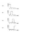
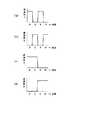
図1は本実施形態のプロジェクタの概略構成図、図2は同プロジェクタで用いる回転カラーフィルターの分光特性を示す図、である。
なお、以下の各図面においては、各構成要素を見やすくするため、構成要素毎に寸法や位置関係の縮尺を異ならせてある。[First Embodiment]
Hereinafter, a first embodiment of the present invention will be described with reference to FIGS.
In this embodiment, a configuration example of a liquid crystal projector using one light source and one transmissive liquid crystal light valve will be described.
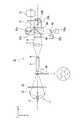
FIG. 1 is a schematic configuration diagram of a projector according to the present embodiment, and FIG. 2 is a diagram illustrating spectral characteristics of a rotating color filter used in the projector.
In the following drawings, the scales of dimensions and positional relationships are different for each component in order to make each component easier to see.
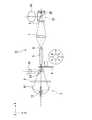
本実施形態のプロジェクタ1は、図1に示すように、光源2、紫外光カットフィルター3、回転カラーフィルター4(光時間分離手段)、ロッドインテグレータ5、リレーレンズ6,7,8、透過型液晶ライトバルブ9(光変調素子、以下、単に液晶ライトバルブということもある)、投写レンズ10(投写手段)から概略構成されている。光源2は、可視光と赤外光とを含む光を射出可能な光源である。具体的には、高圧水銀ランプ、メタルハライドランプ、キセノンランプ、ハロゲンランプ等の白色光と赤外光とを含む光を射出するランプを用いることができる。さらに、光源には、ランプの他、白色光を放射する有機EL素子や無機EL素子、FEDも使用可能である。ランプ11から射出された照明光は、リフレクター12で集光され、紫外光カットフィルター3に入射し、紫外光カットフィルター3によって不要な紫外光が除去される。 As shown in FIG. 1, the projector 1 according to the present embodiment includes a
紫外光カットフィルター3から射出された光は回転カラーフィルター4に入射する。回転カラーフィルター4は、図2(a)〜(d)に示すように、透過波長域が異なり、面積が略同一の4つのカラーフィルターを有しており、入射した光は、波長域が互いに異なる青色光(B光)、緑色光(G光)、赤色光(R光)の可視光と赤外光(IR光)とに時間的に連続して分離される。回転カラーフィルター4は1/60秒で1回転している(60Hzで駆動している)ため、概ね1/240秒毎に射出される光がB光、G光、R光、IR光、B光、…の順で連続的に切り替わる。時間的に分離された各光は、ロッドインテグレータ5、リレーレンズ6,7,8を経て、時分割駆動の液晶ライトバルブ9に順次入射する。 The light emitted from the ultraviolet light cut
なお、ここでは一例として、青色光:概ね380nm〜495nmの波長域の光、緑色光:概ね495nm〜585nmの波長域の光、赤色光:概ね585nm〜720nmの波長域の光、赤外光:概ね720nm〜1100nmを想定している。人間の視認波長域は一般的には380〜780nmと言われているが、実際には720nm以上になるとほとんど視感度を持たない。また、撮像素子の主流であるSi系フォトセンサーの感度限界は概ね1100nmである。 Here, as an example, blue light: light in a wavelength range of approximately 380 nm to 495 nm, green light: light in a wavelength range of approximately 495 nm to 585 nm, red light: light in a wavelength range of approximately 585 nm to 720 nm, infrared light: Approximately 720 nm to 1100 nm are assumed. The visible wavelength range for human beings is generally said to be 380 to 780 nm, but in reality, when the wavelength is 720 nm or more, there is almost no visibility. In addition, the sensitivity limit of the Si-based photosensor that is the mainstream of the image sensor is approximately 1100 nm.
時間的に分離された各光は時分割駆動の液晶ライトバルブ9に順次入射し、外部からの情報に基づいて変調された後、画像情報を内包した変調光として時間的に連続して射出される(勿論、液晶ライトバルブ9も1/240秒毎に画像データが書き換えられる)。図1の構成においては、ロッドインテグレータ5を用いた均一照明系(照度分布の均一化手段)とリレーレンズ系とを備えているが、その他、偏光変換照明系などを備えた構成としても良い。 Each time-separated light sequentially enters the time-division-driven liquid crystal
図示は省略したが、液晶ライトバルブ9の光入射側および光射出側には一対の偏光子が配置され、液晶ライトバルブ9を通過する光の偏光状態を制御して変調光の位相情報を強度情報に変換し、表示画像を形成する。液晶ライトバルブ9には変調光として赤外光が入射されるため、光吸収が少ない光反射型偏光子(この場合には光入射側に限定)、あるいは金属粒子を含有した耐熱性に優れた光吸収型偏光子(この場合は光入射側、光射出側の双方に設置可能)を配置することが望ましい。これにより、帯熱による偏光子や液晶ライトバルブ9の劣化を防ぎ、コントラストの高い画像形成を実現することができる。具体的に、光反射型偏光子としては、金属ワイヤーを微細ピッチで周期的に配列したワイヤーグリッド偏光子、複屈折率の異なる2種類の透明素材を微細ピッチで周期的に積層したDBEF板(商品名:住友スリーエム社)を使用でき、光吸収型偏光子としては、形状異方性を有する金属粒子を配向させたポーラコア(商品名:コーニング社)等を使用できる。 Although not shown, a pair of polarizers are arranged on the light incident side and the light exit side of the liquid crystal
液晶ライトバルブ9から射出された画像情報を内包した変調光は投写レンズ10によって図示しないスクリーン上に投写される。人間の視覚特性から、投写された青色光、緑色光、赤色光、赤外光は時間的に分離されずに、赤外画像が重畳されたカラーの可視画像として視認される。 The modulated light including the image information emitted from the liquid crystal
ところで、ガラス硝材やプラスチック樹脂はその屈折率に波長依存性を有するため、これらの素材を用いる投写レンズ10では焦点距離(焦点位置)が波長によって異なる現象(光学収差)を生じる。その結果、表示画像のフォーカスぼけや解像度の低下、色のにじみ等が発生し、画質低下を招く。本実施形態のプロジェクタ1でも、可視画像のみを表示する通常のプロジェクタと同様、異なる分散特性を有するガラス硝材を多数用いることで光学収差の発生を低減できるが、特に、アッベ数の大きな(屈折率の波長依存性が小さい)媒質を用いたり、屈折率の波長依存性が特異な特性を有する異常分散素材を用いる等の方法が効果的である。あるいは、液晶ライトバルブ9と投写レンズ10との間に屈折率の波長依存性を補正する光学素子を配置しても良い。 By the way, since glass glass material and plastic resin have wavelength dependency in the refractive index, a phenomenon (optical aberration) in which the focal length (focal position) differs depending on the wavelength occurs in the
また、本実施形態のプロジェクタ1は、赤外画像を表示している期間において可視画像の周辺部等の目立たない箇所に、現在赤外画像を表示していることを示す、可視画像によるマーカーを表示する機能を備えている。これにより、人には視認できない赤外画像を表示しているか否かをカメラ等の撮像素子を用いることなく、鑑賞者やプロジェクタの使用者が容易に判別できる。なお、可視画像でのマーカーの表示に代えて、赤外画像を表示中であることを示すインジケータ類をプロジェクタ本体に設置する等の構成であってもよい。 In addition, the projector 1 according to the present embodiment provides a marker based on the visible image that indicates that the infrared image is currently displayed in an inconspicuous portion such as a peripheral portion of the visible image during the period in which the infrared image is displayed. It has a display function. Thereby, it is possible for a viewer or a projector user to easily determine whether an infrared image that cannot be visually recognized by a person is displayed without using an imaging device such as a camera. Instead of displaying the marker in the visible image, an indicator indicating that the infrared image is being displayed may be installed on the projector body.
赤外画像は人には視認できないが、CCDやCMOSセンサー等の撮像素子を搭載したカメラや赤外線カメラ等を通して見ることができる。そのため、大まかな画像は可視画像として表示し、それらと関連する子細な情報は赤外画像として表示するようにすれば、情報量と見やすさの双方を両立することができる。また、赤外画像内の情報をネットワーク上の情報源にアクセスするための情報(例えば、URLやIPアドレス)と関連付けておけば、ネットワークに接続可能なカメラ付き携帯端末で赤外画像を撮像するだけで、詳細情報を簡単に得ることができる。 Infrared images are not visible to humans, but can be viewed through a camera equipped with an image sensor such as a CCD or CMOS sensor, an infrared camera, or the like. Therefore, if the rough image is displayed as a visible image and the detailed information related to the image is displayed as an infrared image, both the amount of information and the ease of viewing can be achieved. In addition, if information in an infrared image is associated with information for accessing an information source on the network (for example, URL or IP address), an infrared image is captured by a camera-equipped mobile terminal that can be connected to the network. Detailed information can be easily obtained.
この種の使い方を想定した場合、本実施形態のプロジェクタ1では、カラーの可視画像に不可視の赤外画像を画素単位で重畳させて表示できるため、両画像の細かな関連付け、表示制御が可能となる。また、本実施形態のプロジェクタ1では、可視光の波長域と赤外光の波長域とが重ならないように波長の切り分けを行っているため、両光のカットオフ波長に対応した光フィルターを備えたカメラを用いれば、可視画像と赤外画像との正確な切り分けができ、一方の画像だけを選択的に読み取ることができる。 Assuming this type of usage, the projector 1 of the present embodiment can display an invisible infrared image superimposed on a color visible image in units of pixels, so that it is possible to finely associate and control display of both images. Become. Further, in the projector 1 according to the present embodiment, since the wavelength is separated so that the wavelength range of visible light and the wavelength range of infrared light do not overlap, an optical filter corresponding to the cutoff wavelength of both lights is provided. If a camera is used, a visible image and an infrared image can be accurately separated, and only one image can be selectively read.
以上のように、本実施形態のプロジェクタ1によれば、カラーの可視画像と不可視の赤外画像の表示状態を独立に制御できるとともに、両画像を一つのスクリーン上に正確に重畳した状態で表示することができ、表示情報(画像や映像)の制御が可能となる。また、可視画像と赤外画像の重畳表示を1台のプロジェクタで行えるため、プロジェクタを移動させた場合であっても可視画像と赤外画像の表示位置を合わせ込む作業が必要なく、使い勝手に優れたものとなる。また、表示システム全体を小型化することができるため、携帯性に優れたものとなる。 As described above, according to the projector 1 of the present embodiment, the display state of a color visible image and an invisible infrared image can be controlled independently, and both images are displayed in a state of being accurately superimposed on one screen. Display information (images and videos) can be controlled. In addition, since the visible image and infrared image can be superimposed and displayed with a single projector, there is no need to align the display position of the visible image and the infrared image even when the projector is moved, making it easy to use. It will be. Further, since the entire display system can be reduced in size, it is excellent in portability.
なお、本実施形態のプロジェクタ1では、1種類の赤外光で画像表示を行う場合を示したが、互いに波長域が異なる2種類以上の赤外画像を独立して表示する構成としても良く、その場合には表示情報の一層多様な制御が可能となる。勿論、時分割駆動のデューティー比を上げて液晶ライトバルブ9で5種類以上の光(例えば青色光、緑色光、赤色光、2種類以上の赤外光)を独立に変調できる構成とする必要がある。こうすると、例えば、可視画像で表示された文章の翻訳文を2種類の言語で表示するような使い方ができる。この場合、言語毎に異なる波長域の赤外画像として表示すれば、観賞者が必要な翻訳文のみを取得できるため、情報量の確保と見やすさを両立できる。 In the projector 1 of the present embodiment, the case of displaying an image with one type of infrared light has been shown, but two or more types of infrared images having different wavelength ranges may be displayed independently. In that case, it is possible to control the display information more variously. Of course, it is necessary to increase the duty ratio of the time division drive so that the liquid crystal
あるいは、本実施形態では、回転カラーフィルター3が略同一の面積を有する4つのカラーフィルターを有し、波長域が異なる各光が1/240秒毎に射出されるものとしたが、各カラーフィルターの面積を異ならせ、各光の照射時間が異なるようにしても良い。勿論、最少の面積を有するカラーフィルターに対応させて液晶ライトバルブ9の画像データ書き換え時間を高速化する必要がある。特に、光源2からの光に含まれる赤外光の強度が弱い場合には、赤外光を射出するカラーフィルターの面積を他のカラーフィルターの面積よりも広くすれば、赤外光の強度不足を補うことができる。 Alternatively, in the present embodiment, the
[第2の実施の形態]
以下、本発明の第2の実施の形態を図3を参照して説明する。
本実施形態のプロジェクタの基本構成は第1実施形態のプロジェクタと略同様であるが第1実施形態の透過型液晶ライトバルブに代えて、反射型液晶ライトバルブを用いた点が異なっている。
図3は本実施形態のプロジェクタの概略構成図である。なお、図3において、第1実施形態で用いた図1と共通の構成要素には同一の符号を付し、その構成要素についての詳細な説明は省略する。[Second Embodiment]
Hereinafter, a second embodiment of the present invention will be described with reference to FIG.
The basic configuration of the projector according to the present embodiment is substantially the same as that of the projector according to the first embodiment, except that a reflective liquid crystal light valve is used instead of the transmissive liquid crystal light valve according to the first embodiment.
FIG. 3 is a schematic configuration diagram of the projector according to the present embodiment. In FIG. 3, the same reference numerals are given to the same components as those in FIG. 1 used in the first embodiment, and detailed description of the components is omitted.
本実施形態のプロジェクタ21の場合、図3に示すように、リレーレンズ8と反射型液晶ライトバルブ22(光変調素子、以下、単に液晶ライトバルブということもある)との間に偏光ビームスプリッタ(Polarized Beam Spritter,PBS)プリズム23が配置されている。このPBSプリズム23は、光の偏光状態に応じて選択的に特定の偏光を分離する。すなわち、P偏光がPBSプリズム23を透過して液晶ライトバルブ22に入射すると、液晶ライトバルブ22では外部からの情報に基づいて光の偏光状態を変換する(例えばP偏光からS偏光)ことで画像情報を内包させる。したがって、液晶ライトバルブ22に入射したP偏光は画像情報に応じて部分的にS偏光に変換されて射出される。液晶ライトバルブ22から射出された光は再びPBSプリズム23に入射し、偏光状態に応じて選択的に分離され、画像情報に応じた偏光状態を有する光(S偏光)のみが投写レンズ10に入射する。 In the case of the
本実施形態のプロジェクタ21においても、カラーの可視画像と不可視の赤外画像を一つのスクリーン上に正確に重畳させることができ、可視画像と赤外画像の表示位置を合わせ込む作業が必要なく使い勝手に優れたものとなる、表示システムを小型化でき、携帯性に優れたものとなる、といった第1実施形態と同様の効果を得ることができる。 Also in the
また、一般的に反射型液晶ライトバルブは高速応答性に優れるため、単色の画像を連続的に表示することで赤外画像を重畳した可視画像を表示する時分割表示型の光変調素子を用いたプロジェクタには好適である。 In general, reflective liquid crystal light valves are excellent in high-speed response. Therefore, a time-division display type light modulation element that displays a visible image superimposed with an infrared image by continuously displaying a monochrome image is used. It is suitable for the projector which was used.
なお、PBSプリズム23での偏光分離性を高めるために、PBSプリズム23のリレーレンズ8側の入射部と投写レンズ10側の射出部とに偏光子を配置しても良い。特に、PBSプリズム23のリレーレンズ8側の入射部に配置する偏光子としては光吸収が少ない反射型偏光子が好適であり、帯熱による偏光子やPBSプリズム23、液晶ライトバルブ22の劣化を防ぎ、コントラストの高い画像形成を実現できる。反射型偏光子として使えるものの具体例は第1実施形態と同様である。 In order to improve the polarization separation property at the
[第3の実施の形態]
以下、本発明の第3の実施の形態を図4を参照して説明する。
本実施形態のプロジェクタの基本構成は第1実施形態のプロジェクタと略同様であるが第1、第2実施形態の液晶ライトバルブに代えて、時分割駆動の反射型微小ミラーアレイデバイスを用いた点が異なっている。
図4は本実施形態のプロジェクタの概略構成図である。なお、図4において、第1実施形態で用いた図1と共通の構成要素には同一の符号を付し、その構成要素についての詳細な説明は省略する。[Third Embodiment]
Hereinafter, a third embodiment of the present invention will be described with reference to FIG.
The basic configuration of the projector according to the present embodiment is substantially the same as that of the projector according to the first embodiment. However, instead of the liquid crystal light valve according to the first and second embodiments, a time-division driven reflective micromirror array device is used. Is different.
FIG. 4 is a schematic configuration diagram of the projector according to the present embodiment. In FIG. 4, the same reference numerals are given to the same constituent elements as those in FIG. 1 used in the first embodiment, and detailed description thereof will be omitted.
本実施形態のプロジェクタ31の場合、図4に示すように、リレーレンズ8と反射型微小ミラーアレイライトバルブ32(光変調素子、以下、単にミラーアレイライトバルブということもある)との間に、特定角度の入射光を全反射させる全反射面33aを内蔵したTIRプリズム33が配置されている。リレーレンズ8から入射した光は全反射面33aで反射され、ミラーアレイライトバルブ32に入射する。ミラーアレイライトバルブ32は微小ミラーの傾きを2値的に可変な光変調素子であり、外部からの情報に基づいて微小ミラーの角度を変えて反射光の方向を制御する。すなわち、画像を形成する光は投写レンズ10の方向に向けて反射させ、画像を形成しない光は投写レンズ10とは異なる方向に反射させることで表示画像を形成する。これにより、画像を形成する光はTIRプリズム33に入射し、全反射面33aを透過(射出光は全反射面33aに対する入射角が小さいため、反射されない)して投写レンズ10へと至る。一方、画像を形成しない光は、全反射面33aで反射するが、投写レンズ10とは異なる方向に反射され、投写レンズ10には入射しない。 In the case of the
本実施形態のプロジェクタ31においても、カラーの可視画像と不可視の赤外画像を一つのスクリーン上に正確に重畳させることができ、可視画像と赤外画像の表示位置を合わせ込む作業が必要なく使い勝手に優れたものとなる、表示システムを小型化でき、携帯性に優れたものとなる、といった第1、第2実施形態と同様の効果を得ることができる。 In the
また、一般的に反射型微小ミラーアレイライトバルブは高速応答性に優れるため、単色の画像を連続的に表示することで赤外画像を重畳した可視画像を表示する時分割表示型の光変調素子を用いたプロジェクタには好適である。 In general, reflective micromirror array light valves are excellent in high-speed response. Therefore, a time-division display type light modulation element that displays a visible image superimposed with an infrared image by continuously displaying a monochromatic image. It is suitable for a projector using the.
[第4の実施の形態]
以下、本発明の第4の実施の形態を図5、図6を参照して説明する。
本実施形態のプロジェクタの基本構成は第2実施形態のプロジェクタと略同様であるが本実施形態は複数の光源を用いた例であり、赤外光を射出する赤外光用光源を付加した点が異なっている。
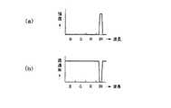
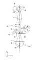
図5は本実施形態のプロジェクタの概略構成図、図6(a)は同プロジェクタで用いる第2光源の分光特性(スペクトル分布)を示す図、図6(b)はダイクロイックミラーの分光特性を示す図、である。なお、図5において、第2実施形態で用いた図3と共通の構成要素には同一の符号を付し、その構成要素についての詳細な説明は省略する。[Fourth Embodiment]
Hereinafter, a fourth embodiment of the present invention will be described with reference to FIGS.
The basic configuration of the projector according to this embodiment is substantially the same as that of the projector according to the second embodiment, but this embodiment is an example using a plurality of light sources, and an infrared light source that emits infrared light is added. Is different.
FIG. 5 is a schematic configuration diagram of the projector according to the present embodiment, FIG. 6A shows the spectral characteristics (spectral distribution) of the second light source used in the projector, and FIG. 6B shows the spectral characteristics of the dichroic mirror. Figure. In FIG. 5, the same reference numerals are given to the same components as those in FIG. 3 used in the second embodiment, and detailed description of the components is omitted.
高圧水銀ランプ、メタルハライドランプ等の放電型の光源の多くは可視光とともに赤外光も放射するが、強度の大きな赤外光を得ることは一般的には難しい(キセノンランプやハロゲンランプでは比較的強度の大きな赤外光を得られる反面、白色光を構成する3原色光の強度バランスが良くない)。また、CCDやCMOSセンサー等の撮像素子は赤外域(概ね1.1μm)まで感度を有するが、800nmを超える波長域では一般的に大幅に感度が低下する。さらに、環境光には赤外光が含まれる場合が多く、赤外画像を鮮明に表示したり、撮像素子で容易に撮像するためには、赤外画像の表示輝度を高める必要がある。 Many discharge-type light sources such as high-pressure mercury lamps and metal halide lamps emit infrared light as well as visible light, but it is generally difficult to obtain high-intensity infrared light. While high-intensity infrared light can be obtained, the intensity balance of the three primary colors constituting white light is not good. An image sensor such as a CCD or CMOS sensor has sensitivity up to the infrared region (approximately 1.1 μm), but the sensitivity is generally greatly reduced in a wavelength region exceeding 800 nm. Furthermore, the ambient light often includes infrared light, and it is necessary to increase the display brightness of the infrared image in order to clearly display the infrared image or to easily capture an image with the image sensor.
そこで、本実施形態のプロジェクタ41では、図5に示すように、第1光源2に加えて赤外光を放射する第2光源42を付加している。第1光源2は、第1〜第3実施形態で用いたものと同様、白色光と赤外光とを含む光を射出可能なランプを用いることができる。第1光源2の射出側には紫外光カットフィルター3が必要に応じて配置される。第2光源42は、赤外光を放射する赤外LEDで構成されている。その他、ハロゲンランプ、キセノンランプ、赤外レーザー等を使用しても良いが、第1光源2からの光と第2光源42からの光とを同一光路に合成する必要があるため、第2光源42としては発光波長域の狭い赤外LEDや赤外レーザー等が特に好適である。第2光源42から射出される光の分光特性を図6(a)に示すが、赤外域にピークを有し、その波長域は第1光源2からの光(赤外光)の波長域と部分的に重なっている。したがって、第1光源2から放射される赤外光の特定波長域の一部が第2光源42からの赤外光によって置き換わることになる。勿論、第1光源2と第2光源42において互いの発光波長域が重ならない場合もあり得る。 Therefore, in the
第1光源2および第2光源42から射出される光の光路上にダイクロイックミラー43(光合成手段)が配置されている。ダイクロイックミラー43の分光特性は、図6(b)に示すように、赤外域の一部の光を反射し、他の光を透過する特性を有しており、反射波長域が図6(a)に示す第2光源42からの光の波長域と概ね一致している。したがって、第1光源2から射出された光は紫外光カットフィルター3によって不要な紫外光が除去された可視光および赤外光となり、この可視光および赤外光の一部と第2光源42から射出された赤外光とがダイクロイックミラー43で合成される(第2光源42と波長域の重なる第1光源2からの赤外光はダイクロイックミラー43で反射され、表示に寄与しない)。すなわち、赤外光について言えば、第1光源2からの比較的ブロードな波長域を持つ赤外光と第2光源42からの比較的ピーキーな波長域を持つ赤外光とが合成されることによって、赤外光全体の強度が高くなる。ダイクロイックミラー43で生成された合成光は、回転カラーフィルター4(分光特性は第1実施形態と同様)、ロッドインテグレータ5、リレーレンズ6,7,8、PBSプリズム23を経て、反射型液晶ライトバルブ22に入射する。PBSプリズム23に入射した光の振る舞いは第2実施形態と同様である。 A dichroic mirror 43 (light combining means) is disposed on the optical path of light emitted from the first
本実施形態のプロジェクタ41においても、カラーの可視画像と不可視の赤外画像を一つのスクリーン上に正確に重畳させることができ、可視画像と赤外画像の表示位置を合わせ込む作業が必要なく使い勝手に優れたものとなる、表示システムを小型化でき、携帯性に優れたものとなる、といった第1〜第3実施形態と同様の効果を得ることができる。 Also in the
そして、上述したように、本実施形態の構成によれば、赤外光を放射する第2光源42を第1光源2とは別個に設けたことで赤外画像の表示輝度を容易に高められるので、赤外光を含む環境光が存在する中でも赤外画像を鮮明に表示したり、撮像素子で容易に撮像することが可能となる。
なお、第2光源に用いた赤外LEDは間欠点灯が可能な光源であるため、回転カラーフィルター4の回転に同期させて発光する構成とすれば、回転カラーフィルター4の後段側(液晶ライトバルブ22側)で第1光源2からの光と第2光源42からの光とを合成する構成としても良い。この構成によれば、第2光源42からの赤外光が回転カラーフィルター4を通過しないため、光利用効率の向上を図りやすい。間欠点灯が可能な他の光源としてはレーザー光源、有機EL素子、無機EL素子、FED、キセノンランプなどがあり、これらを第2光源として利用できる。As described above, according to the configuration of the present embodiment, the display brightness of the infrared image can be easily increased by providing the second
Since the infrared LED used for the second light source is a light source that can be intermittently lit, if it is configured to emit light in synchronization with the rotation of the rotating color filter 4, the rear side of the rotating color filter 4 (liquid crystal light valve) 22 side), the light from the first
[第5の実施の形態]
以下、本発明の第5の実施の形態を図7、図8を参照して説明する。
本実施形態のプロジェクタの基本構成は第4実施形態のプロジェクタと略同様であるが、第4実施形態が赤外光を射出する光源を1つ付加したのに対し、本実施形態では赤外光を射出する光源を2つ付加した点が異なっている。
図7は本実施形態のプロジェクタの概略構成図、図8(a)は同プロジェクタで用いる第1ダイクロイックミラーの分光特性を示す図、図8(b)は第2ダイクロイックミラーの分光特性を示す図、である。なお、図7において、第4実施形態で用いた図5と共通の構成要素には同一の符号を付し、その構成要素についての詳細な説明は省略する。[Fifth Embodiment]
Hereinafter, a fifth embodiment of the present invention will be described with reference to FIGS.
The basic configuration of the projector according to the present embodiment is substantially the same as that of the projector according to the fourth embodiment, but the fourth embodiment adds one light source that emits infrared light, whereas in the present embodiment, infrared light is emitted. The difference is that two light sources for emitting light are added.
FIG. 7 is a schematic configuration diagram of the projector according to the present embodiment, FIG. 8A is a diagram showing the spectral characteristics of the first dichroic mirror used in the projector, and FIG. 8B is a diagram showing the spectral characteristics of the second dichroic mirror. . In FIG. 7, the same reference numerals are given to the same constituent elements as those in FIG. 5 used in the fourth embodiment, and detailed description thereof will be omitted.
本実施形態のプロジェクタ51は、図7に示すように、第1の赤外光(IR1光)を射出する第2光源42に加えて、第1の赤外光とは波長域が重ならない第2の赤外光(IR2光)を射出する第3光源52を備えている。また、第2光源42および第3光源52から射出される赤外光の光路上に第2ダイクロイックミラー53が配置されている。第2ダイクロイックミラー53の分光特性は、図8(b)に示すように、赤外光のうちのIR2光を反射し、IR1光を透過する特性を有している。したがって、第2ダイクロイックミラー53によってIR1光とIR2光とが合成される。さらに、回転カラーフィルター54の射出側であって、第1光源2から射出される光およびIR1光とIR2光の合成光の光路上には第1ダイクロイックミラー55(光合成手段)が配置されている。第1ダイクロイックミラー55の分光特性は、図8(a)に示すように、赤外光のうちのIR2光とIR2光とを反射し、他の波長域の光を透過する特性を有している。したがって、第1ダイクロイックミラー55によって第1光源2から射出された可視光および赤外光の一部とIR1、IR2の合成光とが合成される。 As shown in FIG. 7, the
本実施形態のプロジェクタ51においても、カラーの可視画像と不可視の赤外画像を一つのスクリーン上に正確に重畳させることができ、可視画像と赤外画像の表示位置を合わせ込む作業が必要なく使い勝手に優れたものとなる、表示システムを小型化でき、携帯性に優れたものとなる、といった第1〜第4実施形態と同様の効果を得ることができる。 In the
そして、本実施形態の構成によれば、赤外光を放射する第2光源42、第3光源52を第1光源2とは別個に設けたことで赤外画像の表示輝度を容易に高められるので、赤外光を含む環境光が存在する中でも赤外画像を鮮明に表示したり、撮像素子で容易に撮像することが可能となる。 And according to the structure of this embodiment, the display brightness | luminance of an infrared image can be raised easily by providing the 2nd
さらに、第2光源42や第3光源52に間欠点灯が可能な光源(例えばLED光源、レーザー光源、有機EL素子、無機EL素子、FED、キセノンランプなど)を用いる場合には、本実施形態のように回転カラーフィルター54の後段側(液晶ライトバルブ22側)で第1光源2からの光と第2、第3光源42,52からの光を合成する構成とすることができる。この場合、回転カラーフィルター54からIR1光、IR2光が射出されるタイミングに同期して第2光源42、第3光源52を間欠点灯させる必要がある。この構成によれば、第2光源42、第3光源52からの赤外光が回転カラーフィルター54を通過しないため、光利用効率の向上を図りやすい。また、第4実施形態のような回転カラーフィルター54の入射側にダイクロイックミラーを配置する場合と比べて、ダイクロイックミラーを小径化できる。 Furthermore, when a light source capable of intermittent lighting (for example, an LED light source, a laser light source, an organic EL element, an inorganic EL element, an FED, a xenon lamp, or the like) is used as the second
なお、第4、第5実施形態では、2つ以上の光源からの光をダイクロイックミラーで合成しているため、波長域が重なる光を合成する場合には光損失が避けられない。ところが、2つの光源からの光の偏光状態が異なるように偏光変換(例えば第4実施形態のプロジェクタ41で第1光源2からの光をP偏光、第2光源からの光をS偏光)した後、2つの光を偏光ビームスプリッタ等の偏光素子で合成する構成を採用することもできる。その場合には、波長域が重なる光を合成する場合であっても、光損失を大幅に低減することができる。 In the fourth and fifth embodiments, since light from two or more light sources is combined by a dichroic mirror, light loss is inevitable when combining light with overlapping wavelength ranges. However, after polarization conversion (for example, light from the first
また、第4、第5実施形態では、第1光源2から放射される赤外光の強度を高めるために、第1光源2と類似した波長域の赤外光を放射する第2光源42や第3光源52を用いる場合を想定しているが、第1光源2からは放射されない波長域の赤外光を放射する第2光源や第3光源を用いても良い。その場合も、上記実施形態と同様の構成を採用することができる。 In the fourth and fifth embodiments, in order to increase the intensity of infrared light emitted from the first
[第6の実施の形態]
以下、本発明の第6の実施の形態を図9を参照して説明する。
本実施形態のプロジェクタの基本構成は第2、第4、第5実施形態のプロジェクタと略同様であるが、異なる波長域の光を射出する複数の光源を用いる点が異なっている。
図9は本実施形態のプロジェクタの概略構成図である。なお、図9において、第2実施形態で用いた図3と共通の構成要素には同一の符号を付し、その構成要素についての詳細な説明は省略する。
今までの実施形態では、第1光源として発光波長域が可視の略全域に広がる白色光源を用いることを前提としてきた。これに対して、間欠点灯が可能で発光波長域が互いに殆ど重ならない複数の光源を用いても良く、本実施形態はその構成例である。[Sixth Embodiment]
Hereinafter, a sixth embodiment of the present invention will be described with reference to FIG.
The basic configuration of the projector of this embodiment is substantially the same as that of the projectors of the second, fourth, and fifth embodiments, except that a plurality of light sources that emit light in different wavelength ranges are used.
FIG. 9 is a schematic configuration diagram of the projector according to the present embodiment. In FIG. 9, the same components as those in FIG. 3 used in the second embodiment are denoted by the same reference numerals, and detailed description thereof will be omitted.
In the embodiments so far, it has been assumed that a white light source having a light emission wavelength range that extends over substantially the entire visible range is used as the first light source. On the other hand, a plurality of light sources that can be intermittently lit and whose emission wavelength ranges hardly overlap each other may be used, and this embodiment is a configuration example thereof.
本実施形態のプロジェクタ61は、図9に示すように、発光波長域が互いに異なる4つの光源62B,62G,62R,62IRを用いている。光源としてはLED光源を用いることができるが、その他、レーザー、有機EL素子、無機EL素子、FED等の固体光源を用いることができる。本実施形態においては、青色LED光源62Bから射出されるB光と緑色LED光源62Gから射出されるG光の光路上に第1ダイクロイックミラー63が配置されている。この第1ダイクロイックミラー63により、青色LED光源62Bから射出されるB光と緑色LED光源62Gから射出されるG光とが合成される。また、赤色LED光源62Rから射出されるR光と赤外LED光源62IRから射出されるIR光の光路上に第2ダイクロイックミラー64が配置されている。この第2ダイクロイックミラー64により、赤色LED光源62Rから射出されるR光と赤外LED光源62IRから射出されるIR光とが合成される。そして、B光とG光の合成光とR光とIR光の合成光の光路上に第3ダイクロイックミラー65が配置されている。この第3ダイクロイックミラー65により、B光とG光の合成光とR光とIR光の合成光とが合成される。 As shown in FIG. 9, the
合成された光は、ロッドインテグレータ5、リレーレンズ6,7,8、PBSプリズム23を経て、反射型液晶ライトバルブ22に入射する。PBSプリズム23に入射した光の振る舞いは第2実施形態と同様である。LED光源は間欠点灯が可能であるため、例えば青色LED光源62B、緑色LED光源62G、赤色LED光源62R、赤外LED光源62IR、青色LED光源62B、…というように、各光源を順次連続的に間欠点灯(各光源の点灯時間は概ね1/240秒間)させることによって、反射型液晶ライトバルブ22に時間的に分離された各光が順次照明される。なお、必要に応じて、光フィルターを用いて各光源62B,62G,62R,62IRから射出された光から不要な波長域の光を除去し、発光波長域が互いの光源で全く重ならないようにすることが望ましい。 The synthesized light is incident on the reflective liquid crystal
本実施形態のプロジェクタ61においても、カラーの可視画像と不可視の赤外画像を一つのスクリーン上に正確に重畳させることができ、可視画像と赤外画像の表示位置を合わせ込む作業が必要なく使い勝手に優れたものとなる、表示システムを小型化でき、携帯性に優れたものとなる、といった第1〜第5実施形態と同様の効果を得ることができる。 Also in the
また、本実施形態の構成によれば、発光波長域が互いに重ならない4つの光源62B,62G,62R,62IRを間欠点灯させて使用するため、回転カラーフィルター等の光分離手段を用いる必要がなく、光利用効率の向上や光学系の小型化を実現しやすい。さらに、独立した赤外光用光源(赤外LED光源62IR)を使用できるため、赤外画像の高輝度化を図りやすい。 In addition, according to the configuration of the present embodiment, the four
[第7の実施の形態]
以下、本発明の第7の実施の形態を図10、図11を参照して説明する。
今までの実施形態では1つの光変調素子のみを用いた例について説明したが、本実施形態では複数の光変調素子を用いる例について説明する。特に本実施形態では、時分割駆動の反射型液晶ライトバルブを2つ用いた構成例を挙げる。
図10は本実施形態のプロジェクタの概略構成図、図11(a)、(b)は同プロジェクタで用いる回転カラーフィルターの分光特性を示す図、図11(c)はダイクロイックミラーの分光特性を示す図、図11(d)はダイクロイックプリズムの分光特性を示す図、である。なお、図10において、第1実施形態で用いた図1と共通の構成要素には同一の符号を付し、その構成要素についての詳細な説明は省略する。[Seventh Embodiment]
Hereinafter, a seventh embodiment of the present invention will be described with reference to FIGS.
In the embodiments described so far, an example using only one light modulation element has been described. In the present embodiment, an example using a plurality of light modulation elements will be described. In particular, in this embodiment, a configuration example using two time-division driven reflection type liquid crystal light valves will be described.
FIG. 10 is a schematic configuration diagram of the projector according to the present embodiment, FIGS. 11A and 11B are diagrams illustrating the spectral characteristics of the rotating color filter used in the projector, and FIG. 11C illustrates the spectral characteristics of the dichroic mirror. FIG. 11D is a diagram showing the spectral characteristics of the dichroic prism. In FIG. 10, the same components as those in FIG. 1 used in the first embodiment are denoted by the same reference numerals, and detailed description thereof is omitted.
本実施形態のプロジェクタ71は、図10に示すように、第1液晶ライトバルブ22aと第2液晶ライトバルブ22bの2つの反射型液晶ライトバルブを備えている。回転カラーフィルター72は、図11(a)、(b)に示すように、透過波長域が異なり、面積が略同一の2つのカラーフィルターを有している。すなわち、回転カラーフィルター72は、図11(a)に示すB光とR光を透過しG光とIR光を反射するカラーフィルターと、図11(b)に示すG光とIR光を透過しB光とR光を反射するカラーフィルターとを有している。入射した光は、波長域が互いに異なる第1の光(B光とR光の合成光)と第2の光(G光とIR光の合成光)とに時間的に連続して分離される。回転カラーフィルター72は1/60秒で1回転しており、概ね1/120秒毎に射出される光がB光とR光の合成光、G光とIR光の合成光とに連続的に切り替わる。時間的に分離された各光は、ロッドインテグレータ5、リレーレンズ6,7,8を経て、ダイクロイックミラー73(光空間分離手段)に順次入射する。 As shown in FIG. 10, the
ダイクロイックミラー72は、図11(c)に示すように、B光とG光を透過し、R光とIR光を反射する分光特性を有している。したがって、ダイクロイックミラー72に第1の光が入射している期間において、第1の光は、透過光であるB光と反射光であるR光とに分離され、各々が第1偏光ビームスプリッタプリズム(PBSプリズム)23a、第2PBSプリズム23bを経て、対応する第1液晶ライトバルブ22a、第2液晶ライトバルブ22bに入射する。同様に、第2の光も、透過光であるG光と反射光であるIR光とに分離され、第1PBSプリズム23a、第2PBSプリズム23bを経て、第1液晶ライトバルブ22a、第2液晶ライトバルブ22bに入射する。各PBSプリズム23a,23bに入射する光(偏光)の振る舞いは第2実施形態と同様であるため、説明を省略したが、第1液晶ライトバルブ22a、第2液晶ライトバルブ22bから射出される投射光はS偏光である。 As shown in FIG. 11C, the
ここで、2つの液晶ライトバルブ22a,22bは、第1の光と第2の光の照射間隔に対応して1/120秒毎に画像データが書き換えられる。つまり、各液晶ライトバルブ22a,22bは2種類の光を時分割で連続して変調するため、第2実施形態と比べて、1種類の光あたりの変調時間(画像表示時間)は2倍となる。このような構成では、液晶ライトバルブ22a,22bの変調時間を第2実施形態のプロジェクタと比べて長く取れるため、応答時間が比較的遅い液晶ライトバルブを用いることができる。また、赤外光の変調時間(画像表示時間)が長くなるため、光源2から射出される赤外光の光強度が弱い場合であっても、撮像素子による撮像、画像検出が容易になる。 Here, the image data of the two liquid
各液晶ライトバルブ22a,22bから画像情報を内包して射出された光は、再び対応するPBSプリズム23a,23bに入射し、画像情報に応じた偏光状態を有する光が分離された後、ダイクロイックプリズム74(光合成手段)に入射する。ダイクロイックプリズム74は、図11(d)に示すように、B光とG光を反射し、R光とIR光を透過する分光特性を有している。したがって、各PBSプリズム23a,23bからの光は、ダイクロイックプリズム74によって合成され、投写レンズ10を経て図示しないスクリーン上に連続的に投写される。スクリーン上には、第1の光(B光+R光)による画像と第2の光(G光+IR光)による画像とが1/120秒毎に連続して表示されるが、人間の視覚特性から、投写された画像は時間的に分離されずに、赤外画像が重畳されたカラーの可視画像として視認される。 Light emitted from the liquid
本実施形態のプロジェクタ71においても、カラーの可視画像と不可視の赤外画像を一つのスクリーン上に正確に重畳させることができ、可視画像と赤外画像の表示位置を合わせ込む作業が必要なく使い勝手に優れたものとなる、表示システムを小型化でき、携帯性に優れたものとなる、といった第1〜第6実施形態と同様の効果を得ることができる。 In the
また、本実施形態の構成によれば、上述したように、応答時間が比較的遅い液晶ライトバルブを用いることができる、赤外光の光強度が弱い場合でも撮像素子による撮像、画像検出が容易になる、等の格別な効果が得られる。 Further, according to the configuration of the present embodiment, as described above, a liquid crystal light valve having a relatively slow response time can be used, and even when the light intensity of infrared light is weak, imaging and image detection by the imaging device are easy. It is possible to obtain special effects such as
なお、第2実施形態と同様の観点から、PBSプリズム23a,23bでの偏光分離性を高めるために、PBSプリズム23a,23bのダイクロイックミラー73側の入射部とダイクロイックプリズム74側の射出部とに偏光子を配置しても良い。また、第2PBSプリズム23bとダイクロイックプリズム74との間に波長板(位相差板)を配置し、第2液晶ライトバルブ22bからダイクロイックプリズム74に入射する投写光をP偏光としたり、第2液晶ライトバルブ22bの配置場所を第2PBSプリズム23bの他の面に変えるとともにダイクロイックミラー73と第2PBSプリズム23bとの間に波長板(位相差板)を配置し、第2液晶ライトバルブ22bからの投写光をP偏光としても良い。この構成とした場合、ダイクロイックプリズム74に代えてPBSプリズムを使用することができ、光利用効率を高めやすい。 From the same viewpoint as in the second embodiment, in order to improve the polarization separation property of the
また、本実施形態では、波長域が互いに異なるB光、G光、R光、IR光を、第1の光および第2の光を構成する光と想定したが、本構成の光学系では液晶ライトバルブの数の整数倍の種類の光を扱えるため、例えば波長域が互いに異なる3種類の赤外光を用いることもでき、表示情報の制御をより一層多様化することができる。また、回転カラーフィルター72、ダイクロイックミラー73、ダイクロイックプリズム74などの光学特性を変更することによって、第1液晶ライトバルブ22aで可視光を変調し、第2液晶ライトバルブ22bで赤外光を変調するといった構成も採用することができる。この場合には、赤外光の変調時間(画像表示時間)を長く取ることができるため、光源2から射出される赤外光の光強度が弱い場合であっても、撮像素子による撮像、画像検出が容易になる。 In this embodiment, B light, G light, R light, and IR light having different wavelength ranges are assumed to be light constituting the first light and the second light. However, in the optical system of this structure, liquid crystal is used. Since light of an integer multiple of the number of light valves can be handled, for example, three types of infrared light having different wavelength ranges can be used, and the control of display information can be further diversified. Further, by changing the optical characteristics of the
[第8の実施の形態]
以下、本発明の第8の実施の形態を図12を参照して説明する。
本実施形態では複数の光源と複数の光変調素子を用いる例について説明する。特に本実施形態では、2つの光源と2つの反射型液晶ライトバルブを複数用いた構成例を挙げる。
図12は本実施形態のプロジェクタの概略構成図である。なお、図12において、第7実施形態で用いた図10と共通の構成要素には同一の符号を付し、その構成要素についての詳細な説明は省略する。[Eighth Embodiment]
Hereinafter, an eighth embodiment of the present invention will be described with reference to FIG.
In this embodiment, an example using a plurality of light sources and a plurality of light modulation elements will be described. In particular, in the present embodiment, a configuration example using a plurality of two light sources and two reflective liquid crystal light valves is given.
FIG. 12 is a schematic configuration diagram of the projector according to the present embodiment. In FIG. 12, the same reference numerals are given to the same components as those in FIG. 10 used in the seventh embodiment, and detailed description thereof will be omitted.
本実施形態のプロジェクタ81は、図12に示すように、発光波長域が広い可視光用光源2(第1光源、第1実施形態のプロジェクタと同様)と、赤外光用光源82(第2光源、例えばキセノンランプ、ハロゲンランプ等)とを備えている。可視光用光源2から射出された光は、紫外光・赤外光カットフィルター83によって不要な紫外光と赤外光とが除去された後、第1回転カラーフィルター84(光時間分離手段)に入射し、波長域が互いに異なるB光、G光、R光の可視光に時間的に連続して分離される。第1回転カラーフィルター84は1/60秒で1回転しており、概ね1/180秒毎に照射される光が、B光、G光、R光、B光、…というように連続的に切り替わる。時間的に分離された各色光は、両面反射ミラー85、第1PBSプリズム23aを経て時分割駆動の第1液晶ライトバルブ22aに順次入射する。入射した光は、外部からの情報に基づいて変調され、画像情報を内包した変調光として時間的に連続して射出される(勿論、入射する色光毎の照射時間に対応して第1液晶ライトバルブ22a側も1/180秒毎に画像データが書き換えられる)。 As shown in FIG. 12, the
一方、赤外光用光源82から射出された光は、紫外光・可視光カットフィルター86によって不要な紫外光と可視光が除去された後、第2回転カラーフィルター87(光時間分離手段)に入射し、波長域が互いに異なるIR1光、IR2光の赤外光に時間的に連続して分離される。第2回転カラーフィルター87は1/60秒で1回転しており、概ね1/120秒毎に照射される光がIR1光とIR2光とで交互に切り替わる。時間的に分離された各赤外光は、反射ミラー88、両面反射ミラー85、第2PBSプリズム23bを経て時分割駆動の第2液晶ライトバルブ22bに順次入射する。入射した光は、外部からの情報に基づいて変調され、画像情報を内包した変調光として時間的に連続して射出される(勿論、入射する色光毎の照射時間に対応して第2液晶ライトバルブ22bも1/120秒毎に画像データが書き換えられる)。 On the other hand, the light emitted from the light source for infrared light 82 is removed from unnecessary ultraviolet light and visible light by the ultraviolet light / visible light cut
第1PBSプリズム23a、第2PBSプリズム23bに入射した光(偏光)の振る舞いは第2実施形態と同様である。各液晶ライトバルブ22a,22bから画像情報を内包して射出された光は、再び対応するPBSプリズム23a,23bに入射し、画像情報に応じた偏光状態を有する光が分離された後、ダイクロイックプリズム74で合成され、投写レンズ10を経て図示しないスクリーン上に連続的に投写される。 The behavior of light (polarized light) incident on the
本実施形態のプロジェクタ81においても、カラーの可視画像と不可視の赤外画像を一つのスクリーン上に正確に重畳させることができ、可視画像と赤外画像の表示位置を合わせ込む作業が必要なく使い勝手に優れたものとなる、表示システムを小型化でき、携帯性に優れたものとなる、といった第1〜第7実施形態と同様の効果を得ることができる。 Also in the
また、本実施形態の構成によれば、可視光用光源2、赤外光用光源82と第1、第2液晶ライトバルブ22a,22bとを対応させて用いることによって、液晶ライトバルブ22a,22b毎に変調する光の波長域を限定できるため、複数の光源と複数の液晶ライトバルブとを用いているにもかかわらず、波長域が異なる光毎に表示情報を制御することができる(同一波長域の光が複数の液晶ライトバルブで変調されることがない)。 Further, according to the configuration of the present embodiment, the liquid
なお、本実施形態のプロジェクタ81では、2つの液晶ライトバルブ22a,22bにおける光毎の画像表示時間(サブフレーム時間)が異なっている。すなわち、第1液晶ライトバルブ22aによる1フレーム(3枚のサブフレームで構成される)のカラー画像の表示時間(1/60秒)の間に、第2液晶ライトバルブ22bによる2枚(2フレーム分)の赤外画像が連続的に表示されるように、表示タイミングが設定されている。カラー画像と赤外画像は表示に際して互いに影響を及ぼさないため、2つの液晶ライトバルブ22a,22bにおける光毎の画像表示時間が異なっていても特に問題ない。さらに、赤外光の変調時間(画像表示時間)が長くなるため、赤外光用光源82から射出される赤外光の光強度が弱い場合であっても、撮像素子による撮像、画像検出が容易になる。 In the
[第9の実施の形態]
以下、本発明の第9の実施の形態を図13を参照して説明する。
本実施形態のプロジェクタの基本構成は第8実施形態のプロジェクタと同様であるが、第8実施形態のプロジェクタの赤外光用光源を、間欠点灯が可能な2つの光源に置き換えた点が異なっている。
図13は本実施形態のプロジェクタの概略構成図である。なお、図13において、第8実施形態で用いた図12と共通の構成要素には同一の符号を付し、その構成要素についての詳細な説明は省略する。[Ninth Embodiment]
The ninth embodiment of the present invention will be described below with reference to FIG.
The basic configuration of the projector of this embodiment is the same as that of the projector of the eighth embodiment, except that the infrared light source of the projector of the eighth embodiment is replaced with two light sources that can be intermittently lit. Yes.
FIG. 13 is a schematic configuration diagram of the projector according to the present embodiment. In FIG. 13, the same reference numerals are given to the same components as those in FIG. 12 used in the eighth embodiment, and detailed description of the components is omitted.
本実施形態のプロジェクタ91は、図13に示すように、発光波長域が互いに異なり、間欠点灯が可能な2つの赤外光用光源92a,92b(第2光源)を備えている。これらの光源としてはLED光源を用いることができるが、その他、レーザー、有機EL素子、無機EL素子、FED等の固体光源を用いることができる。第1赤外光用光源92aから射出されるIR1光と第2赤外光用光源92bから射出されるIR2光の光路上にダイクロイックミラー93が配置されている。このダイクロイックミラー93により、IR1光とIR2光とが合成される。第1PBSプリズム23a、第2PBSプリズム23b、ダイクロイックプリズム74に入射した光(偏光)の振る舞いは第8実施形態と同様である。なお、符号94はリレーレンズである。 As shown in FIG. 13, the
本実施形態のプロジェクタ91においても、カラーの可視画像と不可視の赤外画像を一つのスクリーン上に正確に重畳させることができ、可視画像と赤外画像の表示位置を合わせ込む作業が必要なく使い勝手に優れたものとなる、表示システムを小型化でき、携帯性に優れたものとなる、といった第1〜第8実施形態と同様の効果を得ることができる。 Also in the
また、本実施形態の構成によれば、狭帯域かつ間欠点灯が可能な赤外光用光源92a,92bを用いることによって、光学系を小型化、簡素化できるとともに、可視光の強度とは独立させて赤外光の強度を高められるため、赤外画像の高輝度化を図りやすい、という格別の効果が得られる。 Further, according to the configuration of the present embodiment, by using the
さらに、第8実施形態や本実施形態のように赤外光のみを変調する液晶ライトバルブ22bが存在する構成では、赤外画像はサブフレーム画像を持たないため、可視光用液晶ライトバルブよりも解像度が低いライトバルブを赤外光用液晶ライトバルブに使用することができ、液晶ライトバルブの低コスト化、高開口率化による高輝度化や耐熱性の向上を実現することができる。 Furthermore, in the configuration in which the liquid crystal
[第10の実施の形態]
以下、本発明の第10の実施の形態を図14を参照して説明する。
本実施形態のプロジェクタの基本構成は第9実施形態のプロジェクタと略同様であり、光源および照明光学系の構成が若干異なっている。
図14は本実施形態のプロジェクタの概略構成図である。なお、図14において、第9実施形態で用いた図13と共通の構成要素には同一の符号を付し、その構成要素についての詳細な説明は省略する。[Tenth embodiment]
Hereinafter, a tenth embodiment of the present invention will be described with reference to FIG.
The basic configuration of the projector of this embodiment is substantially the same as that of the projector of the ninth embodiment, and the configurations of the light source and the illumination optical system are slightly different.
FIG. 14 is a schematic configuration diagram of the projector according to the present embodiment. In FIG. 14, the same reference numerals are given to the same components as those in FIG. 13 used in the ninth embodiment, and detailed description of the components is omitted.
本実施形態のプロジェクタ101は、図14に示すように、発光波長域が広い第1光源2(第1実施形態のプロジェクタと同様)と、赤外光用光源92b(第2光源)とを備えている。赤外光用光源92bとしてはLED光源を用いることができるが、その他、レーザー、有機EL素子、無機EL素子、FED等の固体光源を用いることができる。この構成例では、回転カラーフィルター4(光時間分離手段)によって、第1光源2から射出された光から波長域が互いに異なるB光、G光、R光の可視光とIR1光の赤外光とを生成している。回転カラーフィルター4は1/60秒で1回転しており、概ね1/240秒毎に照射される光がB光、G光、R光、IR1光、B光、…というように連続的に切り替わり、第1液晶ライトバルブ22aに入射する。一方、赤外光用光源92bから射出された赤外光(IR2光、波長域はIR1光と重ならない)は単独で第2液晶ライトバルブ22bに入射する。第1PBSプリズム23a、第2PBSプリズム23b、ダイクロイックプリズム74に入射した光(偏光)の振る舞いは第8実施形態と同様である。 As shown in FIG. 14, the
本実施形態のプロジェクタ101においても、カラーの可視画像と不可視の赤外画像を一つのスクリーン上に正確に重畳させることができ、可視画像と赤外画像の表示位置を合わせ込む作業が必要なく使い勝手に優れたものとなる、表示システムを小型化でき、携帯性に優れたものとなる、といった第1〜第9実施形態と同様の効果を得ることができる。 Also in the
また、一般的に、CCDやCMOSセンサー等の撮像素子は800nmよりも長い赤外波長域では大幅に感度が低下する。そのため、波長の長い赤外光による赤外画像を表示するためには、本実施形態のように、波長の長い赤外光(IR2光)を放射する光源を単独で用い、その光源からの赤外光を単独で変調する液晶ライトバルブを備えることが望ましい。この構成によれば、波長の長い赤外光の強度を高めやすいため、撮像素子の光感度が大幅に低下する波長域でも確実に赤外画像を撮像することができる。勿論、第1光源からは可視光が、赤外光用光源からはIR1光が射出される構成とすることもできる。 In general, the sensitivity of an image sensor such as a CCD or CMOS sensor is greatly reduced in an infrared wavelength region longer than 800 nm. Therefore, in order to display an infrared image using infrared light having a long wavelength, a light source that emits infrared light having a long wavelength (IR2 light) is used alone as in the present embodiment, and red light from the light source is used. It is desirable to provide a liquid crystal light valve that modulates outside light alone. According to this configuration, since it is easy to increase the intensity of infrared light having a long wavelength, it is possible to reliably capture an infrared image even in a wavelength region in which the optical sensitivity of the image sensor is greatly reduced. Of course, visible light can be emitted from the first light source, and IR1 light can be emitted from the infrared light source.
[第11の実施の形態]
以下、本発明の第11の実施の形態を図15を参照して説明する。
本実施形態のプロジェクタの基本構成は第9実施形態のプロジェクタと略同様であり、光源および照明光学系の構成が異なっている。
図15は本実施形態のプロジェクタの概略構成図である。なお、図15において、第9実施形態で用いた図13と共通の構成要素には同一の符号を付し、その構成要素についての詳細な説明は省略する。[Eleventh embodiment]
The eleventh embodiment of the present invention will be described below with reference to FIG.
The basic configuration of the projector of this embodiment is substantially the same as that of the projector of the ninth embodiment, and the configurations of the light source and the illumination optical system are different.
FIG. 15 is a schematic configuration diagram of the projector according to the present embodiment. In FIG. 15, the same reference numerals are given to the same constituent elements as those in FIG. 13 used in the ninth embodiment, and detailed description thereof will be omitted.
本実施形態のプロジェクタ111は、図15に示すように、発光波長域が互いに異なる4つの光源62B,62G,62R,62IRを備えている。これらの光源としてはLED光源を用いることができるが、その他、レーザー、有機EL素子、無機EL素子、FED等の固体光源を用いることができる。本実施形態においては、青色LED光源62Bから射出される光と緑色LED光源62Gから射出される光の光路上に第1ダイクロイックミラー63が配置されている。この第1ダイクロイックミラー63により、B光とG光とが合成され、合成光が第1液晶ライトバルブ22aに入射する。また、赤色LED光源62Rから射出される光と赤外LED光源62IRから射出される光の光路上に第2ダイクロイックミラー64が配置されている。この第2ダイクロイックミラー64により、R光とIR光とが合成され、合成光が第2液晶ライトバルブ22bに入射する。第1PBSプリズム23a、第2PBSプリズム23b、ダイクロイックプリズム74に入射した光(偏光)の振る舞いは第8実施形態と同様である。 As shown in FIG. 15, the
本実施形態のプロジェクタ111においても、カラーの可視画像と不可視の赤外画像を一つのスクリーン上に正確に重畳させることができ、可視画像と赤外画像の表示位置を合わせ込む作業が必要なく使い勝手に優れたものとなる、表示システムを小型化でき、携帯性に優れたものとなる、といった第1〜第10実施形態と同様の効果を得ることができる。 Also in the
また、本実施形態においては、互いに発光波長域が重ならず、間欠点灯が可能な光源62B,62G,62R,62IRを用いているため、照明光学系を小型化することができる。また、一つの液晶ライトバルブ22a,22bで2種類の光を変調する構成であるため、各光源の点灯時間は概ね1/120秒間、液晶ライトバルブでの変調時間(画像表示時間)もサブフレームあたり概ね1/120秒間と長いため、光源62IRから射出される赤外光の光強度が弱い場合であっても、撮像素子による撮像、画像検出が容易になる。 In the present embodiment, since the light emission wavelength ranges do not overlap each other and the
また、第7〜第11実施形態のプロジェクタ71,81,91,101,111では、波長域が隣接する複数の光を一つの液晶ライトバルブで扱う構成であるため、反射型液晶ライトバルブで必要となるPBSプリズムの狭帯域化による高性能化、低コスト化を実現することができる。 In addition, the
なお、本発明の技術範囲は上記実施の形態に限定されるものではなく、本発明の趣旨を逸脱しない範囲において種々の変更を加えることが可能である。例えば、上記実施形態では、色光を青色光、緑色光、赤色光と想定したが、必ずしもこれら3色に限るものではなく、アプリケーションによって様々な変更が考えられ、例えば4色の色光を用いてもよい。また、上記実施形態で例示した各種構成例の詳細部分は上記の例に限るものではなく、適宜変更が可能である。例えば、光源の射出側に、照度均一化手段としてロッドインテグレータに代えてレンズアレイインテグレータを配置しても良い。 The technical scope of the present invention is not limited to the above embodiment, and various modifications can be made without departing from the spirit of the present invention. For example, in the above embodiment, the color light is assumed to be blue light, green light, and red light. However, the color light is not necessarily limited to these three colors, and various changes may be considered depending on the application. Good. Further, the detailed portions of the various configuration examples exemplified in the above embodiment are not limited to the above examples, and can be changed as appropriate. For example, a lens array integrator may be arranged on the light-emitting side of the light source in place of the rod integrator as illuminance uniformizing means.
1,21,31,41,51,61,71,81,91,101,111…プロジェクタ、2…光源(第1光源、可視光用光源)、4,54,72,84,87…回転カラーフィルター(光時間分離手段)、9…透過型液晶ライトバルブ(光変調素子)、10…投写レンズ(投写手段)、22,22a,22b…反射型液晶ライトバルブ(光変調素子)、32…反射型微小ミラーアレイライトバルブ(光変調素子)、42…第2光源(赤外光用光源)、43…ダイクロイックミラー(光合成手段)、52…第3光源(赤外光用光源)、62B,62G,62R,62IR…光源、73…ダイクロイックミラー(光空間分離手段)、74…ダイクロイックプリズム(光合成手段)、82,92a,92b…赤外光用光源(第2光源)。 1, 21, 31, 41, 51, 61, 71, 81, 91, 101, 111 ... projector, 2 ... light source (first light source, visible light source), 4, 54, 72, 84, 87 ... rotating color Filter (light time separation means), 9 ... Transmission type liquid crystal light valve (light modulation element), 10 ... Projection lens (projection means), 22, 22a, 22b ... Reflection type liquid crystal light valve (light modulation element), 32 ... reflection Type micro mirror array light valve (light modulation element), 42... Second light source (infrared light source), 43... Dichroic mirror (light combining means), 52. 62R, 62IR... Light source, 73... Dichroic mirror (light space separation means), 74.
Claims (10)
Translated fromJapanese前記光源からの光を波長域が異なる一つ以上の可視光と波長域が異なる一つ以上の赤外光とを含む複数の光に時間的に分離する光時間分離手段と、
前記光源からの光を波長域が異なる一つ以上の可視光と波長域が異なる一つ以上の赤外光とを含む複数の光に空間的に分離する光空間分離手段と、
前記光空間分離手段によって分離された各光の光路毎に設けられ、前記光時間分離手段によって分離された複数の光を時間順次に変調する複数の光変調素子と、
前記複数の光変調素子によってそれぞれ変調された複数の変調光を空間的に1つに合成して合成光とする変調光合成手段と、
前記変調光合成手段によって合成された合成光を被投写面上に投写表示する投写手段と、を備え、
前記複数の光変調素子のうちの一つの光変調素子が、液晶ライトバルブで構成されており前記赤外光を変調する赤外光用光変調素子であり、該液晶ライトバルブに付帯する偏光子が、光反射型偏光子または金属を含有する光吸収型偏光子で構成されており、
前記一つ以上の可視光によって形成される可視画像と前記一つ以上の赤外光によって形成される赤外画像とを含む複数の画像を同一の被投写面上に表示することを特徴とするプロジェクタ。A light source that emits light including visible light and infrared light;
An optical time separation means for temporally separating light from the light source into a plurality of lights including one or more visible lights having different wavelength ranges and one or more infrared lights having different wavelength ranges;
Light spatial separation means for spatially separating light from the light source into a plurality of lights including one or more visible lights having different wavelength ranges and one or more infrared lights having different wavelength ranges;
A plurality of light modulation elements that are provided for each light path of each light separated by the light space separation means, and that time-sequentially modulate the plurality of lights separated by the light time separation means;
Modulated light combining means that combines a plurality of modulated lights modulated respectively by the plurality of light modulation elements into one spatially combined light; and
Projection means for projecting and displaying the combined light combined by the modulated light combining means on the projection surface,
One light modulation element of the plurality of light modulation elements is a liquid crystal light valve and is an infrared light modulation element that modulates the infrared light, and a polarizer attached to the liquid crystal light valve Is composed of a light-reflecting polarizer or a light-absorbing polarizer containing a metal,
A plurality of images including a visible image formed by the one or more visible lights and an infrared image formed by the one or more infrared lights are displayed on the same projection surface. projector.
前記第1光源と前記第2光源のうちの一方の光源からの光を波長域が異なる複数の光に時間的に分離する光時間分離手段と、
前記一方の光源からの光の光路に設けられて前記光時間分離手段によって分離された複数の光を時間順次に変調する第1光変調素子と、前記第1光源と前記第2光源のうちの他方の光源からの光の光路に設けられて該光を変調する第2光変調素子とを含む複数の光変調素子と、
前記複数の光変調素子によって変調された複数の変調光を空間的に1つに合成して合成光とする変調光合成手段と、
前記変調光合成手段によって合成された合成光を被投写面上に投写表示する投写手段と、を備え、
前記複数の光変調素子のうちの一つの光変調素子が、液晶ライトバルブで構成されており前記赤外光を変調する赤外光用光変調素子であり、該液晶ライトバルブに付帯する偏光子が、光反射型偏光子または金属を含有する光吸収型偏光子で構成されており、
前記可視光を含む光によって形成される可視画像と前記赤外光を含む光によって形成される赤外画像とを含む複数の画像を同一の被投写面上に表示することを特徴とするプロジェクタ。A plurality of light sources including a first light source that emits light including visible light and a second light source that emits light including infrared light;
An optical time separation means for temporally separatinglight from one of the first light source and the second light source into a plurality of lights having different wavelength ranges;
Afirst light modulation element thatis provided in an optical path of lightfrom the one light sourceand that time-sequentially modulates a plurality of lights separated by the light time separation means,and includes the first light source and the second light source. A plurality of light modulation elementsincluding a second light modulation element that is provided in an optical path of light from the other light source and modulates the light;
Modulated light combining means for spatially combining a plurality of modulated lights modulated by the plurality of light modulation elements into a combined light;
Projection means for projecting and displaying the combined light combined by the modulated light combining means on the projection surface,
One light modulation element of the plurality of light modulation elements is a liquid crystal light valve and is a light modulation element for infrared light that modulates the infrared light, and a polarizer attached to the liquid crystal light valve Is composed of a light-reflecting polarizer or a light-absorbing polarizer containing a metal,
A projector that displays a plurality of images including a visible image formed by light including the visible light and an infrared image formed by light including the infrared light on the same projection surface.
前記第1光源からの光を波長域が異なる複数の光に時間的に分離する第1の光時間分離手段と、
前記第2光源からの光を波長域が異なる複数の光に時間的に分離する第2の光時間分離手段と、
前記第1光源からの光の光路に設けられて前記第1の光時間分離手段によって分離された複数の光を時間順次に変調する第1光変調素子と、前記第2光源からの光の光路に設けられて前記第2の光時間分離手段によって分離された複数の光を時間順次に変調する第2光変調素子とを含む複数の光変調素子と、
前記複数の光変調素子によって変調された複数の変調光を空間的に1つに合成して合成光とする変調光合成手段と、
前記変調光合成手段によって合成された合成光を被投写面上に投写表示する投写手段と、を備え、
前記複数の光変調素子のうちの一つの光変調素子が、液晶ライトバルブで構成されており前記赤外光を変調する赤外光用光変調素子であり、該液晶ライトバルブに付帯する偏光子が、光反射型偏光子または金属を含有する光吸収型偏光子で構成されており、
前記可視光を含む光によって形成される可視画像と前記赤外光を含む光によって形成される赤外画像とを含む複数の画像を同一の被投写面上に表示することを特徴とするプロジェクタ。A plurality of light sources including a first light source that emits light including visible light and a second light source that emits light including infrared light;
Afirst optical time separating means for temporally separated in the wavelength region light of the first lightsource or colleagues different light,
Second light time separation means for temporally separating light from the second light source into a plurality of lights having different wavelength ranges;
Afirst light modulation element thatis provided in an optical path of light from the first light source and that sequentially modulates a plurality of lights separated bythe first optical time separation unit;and an optical path of light from the second light source A plurality of light modulation elementsincluding a second light modulation element that is time-sequentially modulated with the plurality of lights separated by the second light time separation means ,
Modulated light combining means for spatially combining a plurality of modulated lights modulated by the plurality of light modulation elements into a combined light;
Projection means for projecting and displaying the combined light combined by the modulated light combining means on the projection surface,
One light modulation element of the plurality of light modulation elements is a liquid crystal light valve and is a light modulation element for infrared light that modulates the infrared light, and a polarizer attached to the liquid crystal light valve Is composed of a light-reflecting polarizer or a light-absorbing polarizer containing a metal,
A projector that displays a plurality of images including a visible image formed by light including the visible light and an infrared image formed by light including the infrared light on the same projection surface.
前記第1光源及び前記第2光源から射出された前記第1の光及び第2の光のうちの一方の光を変調する第1光変調素子と他方の光を変調する第2光変調素子とを含む複数の光変調素子と、
前記複数の光変調素子によって変調された複数の変調光を空間的に1つに合成して合成光とする変調光合成手段と、
前記変調光合成手段によって合成された合成光を被投写面上に投写表示する投写手段と、を備え、
前記複数の光変調素子のうちの一つの光変調素子が、液晶ライトバルブで構成されており前記赤外光を変調する赤外光用光変調素子であり、該液晶ライトバルブに付帯する偏光子が、光反射型偏光子または金属を含有する光吸収型偏光子で構成されており、
前記可視光を含む光によって形成される可視画像と前記赤外光を含む光によって形成される赤外画像とを含む複数の画像を同一の被投写面上に表示することを特徴とするプロジェクタ。A pluralityof light sources including a first light source that emitsfirst light including visible light and a second light source that emitssecond light including infrared light, wherein light from each light source is sequentially emitted; ,
A first light modulation element that modulates one of the first light and the second light emitted from the first light source and the second light source; and a second light modulation element that modulates the other light; A plurality of light modulation elements including:
Modulated light combining means for spatially combining a plurality of modulated lights modulated by the plurality of light modulation elements into a combined light;
Projection means for projecting and displaying the combined light combined by the modulated light combining means on the projection surface,
One light modulation element of the plurality of light modulation elements is a liquid crystal light valve and is a light modulation element for infrared light that modulates the infrared light, and a polarizer attached to the liquid crystal light valve Is composed of a light-reflecting polarizer or a light-absorbing polarizer containing a metal,
A projector that displays a plurality of images including a visible image formed by light including the visible light and an infrared image formed by light including the infrared light on the same projection surface.
Priority Applications (2)
| Application Number | Priority Date | Filing Date | Title |
|---|---|---|---|
| JP2007017504AJP4395792B2 (en) | 2007-01-29 | 2007-01-29 | projector |
| US12/020,753US8016425B2 (en) | 2007-01-29 | 2008-01-28 | Projector |
Applications Claiming Priority (1)
| Application Number | Priority Date | Filing Date | Title |
|---|---|---|---|
| JP2007017504AJP4395792B2 (en) | 2007-01-29 | 2007-01-29 | projector |
Publications (2)
| Publication Number | Publication Date |
|---|---|
| JP2008185673A JP2008185673A (en) | 2008-08-14 |
| JP4395792B2true JP4395792B2 (en) | 2010-01-13 |
Family
ID=39667553
Family Applications (1)
| Application Number | Title | Priority Date | Filing Date |
|---|---|---|---|
| JP2007017504AExpired - Fee RelatedJP4395792B2 (en) | 2007-01-29 | 2007-01-29 | projector |
Country Status (2)
| Country | Link |
|---|---|
| US (1) | US8016425B2 (en) |
| JP (1) | JP4395792B2 (en) |
Families Citing this family (51)
| Publication number | Priority date | Publication date | Assignee | Title |
|---|---|---|---|---|
| JP4395792B2 (en)* | 2007-01-29 | 2010-01-13 | セイコーエプソン株式会社 | projector |
| WO2009120984A1 (en) | 2008-03-28 | 2009-10-01 | Kopin Corporation | Handheld wireless display device having high-resolution display suitable for use as a mobile internet device |
| US8840249B2 (en)* | 2008-10-31 | 2014-09-23 | Christie Digital Systems, Inc. | Method, system and apparatus for projecting visible and non-visible images |
| WO2010129679A1 (en) | 2009-05-08 | 2010-11-11 | Kopin Corporation | Remote control of host application using motion and voice commands |
| IT1399180B1 (en)* | 2009-06-12 | 2013-04-11 | Sharp Kk | SOLAR SIMULATOR |
| DE102009025127A1 (en)* | 2009-06-17 | 2010-12-23 | Carl Zeiss Surgical Gmbh | Lighting device for an optical observation device |
| JP2011221504A (en)* | 2010-03-26 | 2011-11-04 | Panasonic Corp | Illuminator and projection type image display device using the same |
| CN102207661A (en)* | 2010-03-29 | 2011-10-05 | 影来腾贸易(上海)有限公司 | Projection type light-uniforming system for touch screen |
| US9077915B2 (en)* | 2010-04-07 | 2015-07-07 | Projectiondesign As | Interweaving of IR and visible images |
| TW201201077A (en)* | 2010-06-18 | 2012-01-01 | Nlighten Trading Shanghai Co Ltd | A light uniforming system of projected touch technology |
| TWI448804B (en) | 2010-08-20 | 2014-08-11 | Delta Electronics Inc | Illumination system and projection device comprising the same |
| US9122307B2 (en) | 2010-09-20 | 2015-09-01 | Kopin Corporation | Advanced remote control of host application using motion and voice commands |
| US10013976B2 (en) | 2010-09-20 | 2018-07-03 | Kopin Corporation | Context sensitive overlays in voice controlled headset computer displays |
| JP5587120B2 (en)* | 2010-09-30 | 2014-09-10 | 富士フイルム株式会社 | Endoscope light source device |
| EP2650727A4 (en)* | 2010-12-08 | 2014-05-21 | Nec Display Solutions Ltd | Lighting optical system and projection display device comprising same |
| US9111326B1 (en) | 2010-12-21 | 2015-08-18 | Rawles Llc | Designation of zones of interest within an augmented reality environment |
| US9134593B1 (en)* | 2010-12-23 | 2015-09-15 | Amazon Technologies, Inc. | Generation and modulation of non-visible structured light for augmented reality projection system |
| US8905551B1 (en) | 2010-12-23 | 2014-12-09 | Rawles Llc | Unpowered augmented reality projection accessory display device |
| US8845110B1 (en) | 2010-12-23 | 2014-09-30 | Rawles Llc | Powered augmented reality projection accessory display device |
| US8845107B1 (en) | 2010-12-23 | 2014-09-30 | Rawles Llc | Characterization of a scene with structured light |
| US9721386B1 (en) | 2010-12-27 | 2017-08-01 | Amazon Technologies, Inc. | Integrated augmented reality environment |
| US9607315B1 (en) | 2010-12-30 | 2017-03-28 | Amazon Technologies, Inc. | Complementing operation of display devices in an augmented reality environment |
| US9508194B1 (en) | 2010-12-30 | 2016-11-29 | Amazon Technologies, Inc. | Utilizing content output devices in an augmented reality environment |
| JP5174290B2 (en)* | 2011-01-28 | 2013-04-03 | オリンパスメディカルシステムズ株式会社 | Illumination device and observation system |
| JP2012234149A (en)* | 2011-04-20 | 2012-11-29 | Panasonic Corp | Image projection device |
| CN109116985A (en) | 2011-05-10 | 2019-01-01 | 寇平公司 | The method that control information is shown |
| US9118782B1 (en) | 2011-09-19 | 2015-08-25 | Amazon Technologies, Inc. | Optical interference mitigation |
| WO2013101438A1 (en) | 2011-12-29 | 2013-07-04 | Kopin Corporation | Wireless hands-free computing head mounted video eyewear for local/remote diagnosis and repair |
| WO2013163293A1 (en) | 2012-04-25 | 2013-10-31 | Kopin Corporation | Instant translation system |
| US8929954B2 (en) | 2012-04-25 | 2015-01-06 | Kopin Corporation | Headset computer (HSC) as auxiliary display with ASR and HT input |
| US9442290B2 (en) | 2012-05-10 | 2016-09-13 | Kopin Corporation | Headset computer operation using vehicle sensor feedback for remote control vehicle |
| CN105143943B (en)* | 2012-12-26 | 2018-09-11 | 神画科技(深圳)有限公司 | Optical projection system with infrared light supply |
| TWI486640B (en)* | 2012-12-28 | 2015-06-01 | Delta Electronics Inc | Stereoscopic projection device and display method thereof |
| US9301085B2 (en) | 2013-02-20 | 2016-03-29 | Kopin Corporation | Computer headset with detachable 4G radio |
| US9140444B2 (en) | 2013-08-15 | 2015-09-22 | Medibotics, LLC | Wearable device for disrupting unwelcome photography |
| CN104980721B (en)* | 2014-04-02 | 2019-03-29 | 深圳光峰科技股份有限公司 | A light source system and a projection system |
| US9574747B2 (en)* | 2014-06-09 | 2017-02-21 | Telelumen, LLC | Spectrally controllable light valve |
| CN104360477B (en)* | 2014-12-11 | 2016-09-21 | 青岛橡胶谷知识产权有限公司 | The continuously adjustable point target of frequency and amplitudes based on twin columns lens is as vibrating device |
| JP6601790B2 (en)* | 2015-06-30 | 2019-11-06 | パナソニックIpマネジメント株式会社 | Real-time measurement and projection apparatus and three-dimensional projection and measurement apparatus |
| JP2016127587A (en)* | 2015-09-03 | 2016-07-11 | 株式会社Fove | Head-mounted display |
| CN106308751A (en)* | 2016-08-23 | 2017-01-11 | 江苏鹰利视医疗器械有限公司 | Device for achieving narrow-band or broad-band spectrum combined lighting and method thereof |
| TWI726073B (en)* | 2017-03-16 | 2021-05-01 | 揚明光學股份有限公司 | Optical system |
| DE102017114115A1 (en)* | 2017-06-26 | 2018-12-27 | Carl Zeiss Jena Gmbh | Lighting device for a light modulator having a projector |
| JP7302472B2 (en)* | 2017-07-12 | 2023-07-04 | ソニーグループ株式会社 | image display device |
| JP6930265B2 (en)* | 2017-07-24 | 2021-09-01 | セイコーエプソン株式会社 | projector |
| CN107300783B (en)* | 2017-08-15 | 2019-08-16 | 天津津航技术物理研究所 | A kind of visible light, laser and middle infrared band recombination dichroic elements and design method |
| JP7336762B2 (en)* | 2019-04-16 | 2023-09-01 | パナソニックIpマネジメント株式会社 | Light source device and projection display device |
| JP2020187165A (en)* | 2019-05-10 | 2020-11-19 | キヤノン株式会社 | Image projection device |
| CN112147835B (en)* | 2019-06-28 | 2023-04-21 | 深圳光峰科技股份有限公司 | Optical engine system and display equipment |
| CN110381244B (en)* | 2019-08-26 | 2021-02-02 | 浙江大华技术股份有限公司 | Camera and method for improving image quality under low illumination |
| CN117120924A (en)* | 2021-04-27 | 2023-11-24 | 松下知识产权经营株式会社 | Projection system |
Family Cites Families (28)
| Publication number | Priority date | Publication date | Assignee | Title |
|---|---|---|---|---|
| JPH07270911A (en) | 1994-03-30 | 1995-10-20 | Jamco Corp | LCD projector |
| US6497485B1 (en)* | 2000-01-20 | 2002-12-24 | Seiko Epson Corporation | Image projection system having uniform brightness |
| US6018374A (en)* | 1996-06-25 | 2000-01-25 | Macrovision Corporation | Method and system for preventing the off screen copying of a video or film presentation |
| JP3299216B2 (en) | 1999-01-29 | 2002-07-08 | エヌイーシービューテクノロジー株式会社 | Video projection device |
| US6950532B1 (en)* | 2000-04-24 | 2005-09-27 | Cinea Inc. | Visual copyright protection |
| US6809792B1 (en)* | 2000-10-09 | 2004-10-26 | Eastman Kodak Company | Spectral watermarking for motion picture image data |
| US6742901B2 (en)* | 2001-05-16 | 2004-06-01 | Sony Corporation | Imaging prevention method and system |
| DE10227468A1 (en)* | 2002-06-20 | 2004-01-15 | Bayerische Motoren Werke Ag | Projection system and method |
| US6736514B2 (en)* | 2002-06-21 | 2004-05-18 | Eastman Kodak Company | Imaging apparatus for increased color gamut using dual spatial light modulators |
| US7390092B2 (en)* | 2002-11-08 | 2008-06-24 | Belliveau Richard S | Image projection lighting devices with visible and infrared imaging |
| US20040145708A1 (en)* | 2003-01-24 | 2004-07-29 | Evans & Sutherland Computer Corporation | Infrared projector |
| US20040150794A1 (en)* | 2003-01-30 | 2004-08-05 | Eastman Kodak Company | Projector with camcorder defeat |
| US6811267B1 (en)* | 2003-06-09 | 2004-11-02 | Hewlett-Packard Development Company, L.P. | Display system with nonvisible data projection |
| JP2005017583A (en) | 2003-06-25 | 2005-01-20 | Seiko Epson Corp | projector |
| CA2535564A1 (en)* | 2003-08-19 | 2005-03-03 | Thomson Licensing | Theater identification system utilizing identifiers projected through a screen |
| JP4140898B2 (en) | 2003-08-20 | 2008-08-27 | 日本電信電話株式会社 | Information presentation device and method of using information presentation device |
| US20050140942A1 (en)* | 2003-12-31 | 2005-06-30 | Steven Squires | Image device jamming apparatus and method |
| JP4882203B2 (en) | 2004-02-16 | 2012-02-22 | セイコーエプソン株式会社 | Optical display device and projection display device |
| JP2005321524A (en) | 2004-05-07 | 2005-11-17 | Seiko Epson Corp | Light source device and projector |
| JP4021473B1 (en) | 2004-09-07 | 2007-12-12 | ヒューレット−パッカード デベロップメント カンパニー エル.ピー. | Display system with invisible data projection function |
| JP2006301300A (en) | 2005-04-20 | 2006-11-02 | Seiko Epson Corp | Image display device |
| JP4729999B2 (en)* | 2005-06-28 | 2011-07-20 | 富士ゼロックス株式会社 | Information processing system, information processing apparatus, information processing method, and computer program |
| JP2007017516A (en) | 2005-07-05 | 2007-01-25 | Plus Vision Corp | Projector provided with function of projecting two-dimensional positional information |
| JP4395792B2 (en)* | 2007-01-29 | 2010-01-13 | セイコーエプソン株式会社 | projector |
| EP2208354A4 (en)* | 2007-10-10 | 2010-12-22 | Gerard Dirk Smits | Image projector with reflected light tracking |
| US20090180079A1 (en)* | 2008-01-16 | 2009-07-16 | Oakley Willliam S | Projected Overlay for Copy Degradation |
| US8439503B2 (en)* | 2008-08-06 | 2013-05-14 | Disney Enterprises, Inc. | Infrared imaging projection |
| US8840249B2 (en)* | 2008-10-31 | 2014-09-23 | Christie Digital Systems, Inc. | Method, system and apparatus for projecting visible and non-visible images |
- 2007
- 2007-01-29JPJP2007017504Apatent/JP4395792B2/ennot_activeExpired - Fee Related
- 2008
- 2008-01-28USUS12/020,753patent/US8016425B2/ennot_activeExpired - Fee Related
Also Published As
| Publication number | Publication date |
|---|---|
| US20080180640A1 (en) | 2008-07-31 |
| US8016425B2 (en) | 2011-09-13 |
| JP2008185673A (en) | 2008-08-14 |
Similar Documents
| Publication | Publication Date | Title |
|---|---|---|
| JP4395792B2 (en) | projector | |
| JP4341680B2 (en) | projector | |
| JP5045250B2 (en) | projector | |
| JP3057232B2 (en) | Two-panel LCD projector | |
| TWI228634B (en) | Image display apparatus and projector | |
| JP3635867B2 (en) | Projection type liquid crystal display device | |
| US8593579B2 (en) | Projection display | |
| US7841725B2 (en) | Image display device and projector | |
| JP2005507086A5 (en) | ||
| JP5034779B2 (en) | Lighting device and projector | |
| JP6942510B2 (en) | Projection type display device | |
| JP5141044B2 (en) | projector | |
| JPH11174372A (en) | Illumination device for projection device and projection device | |
| JP3639842B2 (en) | Projection display | |
| JP5625932B2 (en) | Projection display | |
| JP4335664B2 (en) | Projection type image display device, rear projection type image display device, optical unit and screen unit | |
| JP2008275909A (en) | Projection display device | |
| JP2010020030A (en) | Projector apparatus and image synthesizing device for the same | |
| JP4432602B2 (en) | Projection display | |
| TW200921243A (en) | Projection device | |
| TW201428415A (en) | Illumination system and projection device comprising the same | |
| JP2008134321A (en) | Projector with imaging function | |
| JP2007206308A (en) | Projection display | |
| WO2016152033A1 (en) | Projector | |
| JP2009128856A (en) | Projector |
Legal Events
| Date | Code | Title | Description |
|---|---|---|---|
| A977 | Report on retrieval | Free format text:JAPANESE INTERMEDIATE CODE: A971007 Effective date:20090121 | |
| A131 | Notification of reasons for refusal | Free format text:JAPANESE INTERMEDIATE CODE: A131 Effective date:20090127 | |
| A521 | Request for written amendment filed | Free format text:JAPANESE INTERMEDIATE CODE: A523 Effective date:20090330 | |
| A131 | Notification of reasons for refusal | Free format text:JAPANESE INTERMEDIATE CODE: A131 Effective date:20090609 | |
| A521 | Request for written amendment filed | Free format text:JAPANESE INTERMEDIATE CODE: A523 Effective date:20090807 | |
| A521 | Request for written amendment filed | Free format text:JAPANESE INTERMEDIATE CODE: A821 Effective date:20090810 | |
| TRDD | Decision of grant or rejection written | ||
| A01 | Written decision to grant a patent or to grant a registration (utility model) | Free format text:JAPANESE INTERMEDIATE CODE: A01 Effective date:20090924 | |
| A01 | Written decision to grant a patent or to grant a registration (utility model) | Free format text:JAPANESE INTERMEDIATE CODE: A01 | |
| A61 | First payment of annual fees (during grant procedure) | Free format text:JAPANESE INTERMEDIATE CODE: A61 Effective date:20091007 | |
| FPAY | Renewal fee payment (event date is renewal date of database) | Free format text:PAYMENT UNTIL: 20121030 Year of fee payment:3 | |
| R150 | Certificate of patent or registration of utility model | Ref document number:4395792 Country of ref document:JP Free format text:JAPANESE INTERMEDIATE CODE: R150 Free format text:JAPANESE INTERMEDIATE CODE: R150 | |
| FPAY | Renewal fee payment (event date is renewal date of database) | Free format text:PAYMENT UNTIL: 20121030 Year of fee payment:3 | |
| FPAY | Renewal fee payment (event date is renewal date of database) | Free format text:PAYMENT UNTIL: 20131030 Year of fee payment:4 | |
| S531 | Written request for registration of change of domicile | Free format text:JAPANESE INTERMEDIATE CODE: R313531 | |
| R350 | Written notification of registration of transfer | Free format text:JAPANESE INTERMEDIATE CODE: R350 | |
| LAPS | Cancellation because of no payment of annual fees |