JP4395770B2 - Method for detecting disconnection of charge line of battery charger and battery charger - Google Patents
Method for detecting disconnection of charge line of battery charger and battery chargerDownload PDFInfo
- Publication number
- JP4395770B2 JP4395770B2JP2005152967AJP2005152967AJP4395770B2JP 4395770 B2JP4395770 B2JP 4395770B2JP 2005152967 AJP2005152967 AJP 2005152967AJP 2005152967 AJP2005152967 AJP 2005152967AJP 4395770 B2JP4395770 B2JP 4395770B2
- Authority
- JP
- Japan
- Prior art keywords
- voltage
- battery
- charging line
- value
- generator
- Prior art date
- Legal status (The legal status is an assumption and is not a legal conclusion. Google has not performed a legal analysis and makes no representation as to the accuracy of the status listed.)
- Expired - Fee Related
Links
- 238000000034methodMethods0.000titleclaimsdescription41
- 230000005284excitationEffects0.000claimsdescription125
- 238000001514detection methodMethods0.000claimsdescription85
- 238000004891communicationMethods0.000claimsdescription75
- 238000010248power generationMethods0.000claimsdescription50
- 230000007423decreaseEffects0.000claimsdescription21
- 238000004804windingMethods0.000description37
- 230000005856abnormalityEffects0.000description15
- 239000000284extractSubstances0.000description14
- 238000006243chemical reactionMethods0.000description11
- 230000000694effectsEffects0.000description7
- 238000010586diagramMethods0.000description6
- 238000012545processingMethods0.000description5
- 239000000446fuelSubstances0.000description3
- 230000001052transient effectEffects0.000description3
- 230000002159abnormal effectEffects0.000description2
- 238000007599dischargingMethods0.000description2
- 230000004907fluxEffects0.000description2
- 238000010992refluxMethods0.000description2
- 230000009466transformationEffects0.000description2
- 230000001133accelerationEffects0.000description1
- 238000013459approachMethods0.000description1
- 230000003247decreasing effectEffects0.000description1
- 238000005265energy consumptionMethods0.000description1
- 238000003912environmental pollutionMethods0.000description1
- 230000007257malfunctionEffects0.000description1
- 238000011160researchMethods0.000description1
Images


Classifications
- H—ELECTRICITY
- H02—GENERATION; CONVERSION OR DISTRIBUTION OF ELECTRIC POWER
- H02J—CIRCUIT ARRANGEMENTS OR SYSTEMS FOR SUPPLYING OR DISTRIBUTING ELECTRIC POWER; SYSTEMS FOR STORING ELECTRIC ENERGY
- H02J7/00—Circuit arrangements for charging or depolarising batteries or for supplying loads from batteries
- H02J7/0047—Circuit arrangements for charging or depolarising batteries or for supplying loads from batteries with monitoring or indicating devices or circuits
- G—PHYSICS
- G01—MEASURING; TESTING
- G01R—MEASURING ELECTRIC VARIABLES; MEASURING MAGNETIC VARIABLES
- G01R31/00—Arrangements for testing electric properties; Arrangements for locating electric faults; Arrangements for electrical testing characterised by what is being tested not provided for elsewhere
- G01R31/50—Testing of electric apparatus, lines, cables or components for short-circuits, continuity, leakage current or incorrect line connections
- G01R31/54—Testing for continuity
- G—PHYSICS
- G01—MEASURING; TESTING
- G01R—MEASURING ELECTRIC VARIABLES; MEASURING MAGNETIC VARIABLES
- G01R31/00—Arrangements for testing electric properties; Arrangements for locating electric faults; Arrangements for electrical testing characterised by what is being tested not provided for elsewhere
- G01R31/50—Testing of electric apparatus, lines, cables or components for short-circuits, continuity, leakage current or incorrect line connections
- G01R31/58—Testing of lines, cables or conductors
- G—PHYSICS
- G01—MEASURING; TESTING
- G01R—MEASURING ELECTRIC VARIABLES; MEASURING MAGNETIC VARIABLES
- G01R31/00—Arrangements for testing electric properties; Arrangements for locating electric faults; Arrangements for electrical testing characterised by what is being tested not provided for elsewhere
- G01R31/005—Testing of electric installations on transport means
- G01R31/006—Testing of electric installations on transport means on road vehicles, e.g. automobiles or trucks
Landscapes
- Physics & Mathematics (AREA)
- General Physics & Mathematics (AREA)
- Engineering & Computer Science (AREA)
- Power Engineering (AREA)
- Control Of Eletrric Generators (AREA)
- Control Of Charge By Means Of Generators (AREA)
- Emergency Protection Circuit Devices (AREA)
Description
Translated fromJapanese本発明は、充電線を介してバッテリを充電するバッテリ充電装置の充電線断線検出方法及びバッテリ充電装置に関する。 The present invention relates to a method for detecting disconnection of a charging line of a battery charging device that charges a battery via a charging line and a battery charging device.
車両に搭載されたバッテリと、バッテリを充電する車両用発電機とは、充電線を介して接続されている。従来、この充電線の断線を検出することができるバッテリ充電装置として、例えば、特開昭59−148538号公報に開示されている充電発電機用電圧調整装置や、特開平4−222426号公報に開示されている自動車用バッテリの充電システムがある。 A battery mounted on the vehicle and a vehicle generator that charges the battery are connected via a charging line. Conventionally, as a battery charger capable of detecting the disconnection of the charging line, for example, a voltage generator for a charging generator disclosed in Japanese Patent Laid-Open No. 59-148538 and Japanese Patent Laid-Open No. 4-222426 are disclosed. There is an automotive battery charging system disclosed.
充電発電機用電圧調整装置は、充電発電機と、電圧調整器とから構成されている。充電発電機は発電機と整流器とからなり、その整流出力端子は接続線を介して蓄電池に接続されている。電圧調整器は、充電発電機の整流出力端子に接続されるL端子と、蓄電池の正極端子に接続されるS端子とを備えている。電圧調整器は、L端子とS端子の電圧に基づいて充電発電機の出力電圧を調整する。さらに、L端子とS端子の間の電圧差が一定値以上の場合、充電発電機と蓄電池とを接続している接続線が断線している判断し、充電発電機の発電を停止させて警報する。 The voltage generator for a charging generator is composed of a charging generator and a voltage regulator. The charging generator comprises a generator and a rectifier, and the rectified output terminal is connected to the storage battery via a connection line. The voltage regulator includes an L terminal connected to the rectification output terminal of the charging generator and an S terminal connected to the positive terminal of the storage battery. A voltage regulator adjusts the output voltage of a charging generator based on the voltage of L terminal and S terminal. Furthermore, when the voltage difference between the L terminal and the S terminal is a certain value or more, it is judged that the connection line connecting the charging generator and the storage battery is broken, and the alarm is generated by stopping the power generation of the charging generator. To do.
自動車用バッテリの充電システムは、電流発生器と、スイッチと、表示灯と、電圧調整器とから構成されている。電流発生器は発電機と整流器とからなり、その出力端子はケーブルを介してバッテリに接続されている。電圧調整器は、電流発生器の出力端子に接続される第1入力端子Aと、スイッチ及び表示灯を介してバッテリの正極端子に接続される第2入力端子Lとを備えている。電圧調整器は、第1入力端子Aと第2入力端子Lの電圧に基づいて電流発生器の出力電圧を調整する。さらに、第1入力端子Aと第2入力端子Lの間の電位差があらかじめ定められた基準値を超えた場合、電流発生器とバッテリとを接続しているケーブルが断線していると判断し、表示灯を点灯させて警報する。 The battery charging system for an automobile includes a current generator, a switch, an indicator lamp, and a voltage regulator. The current generator includes a generator and a rectifier, and its output terminal is connected to the battery via a cable. The voltage regulator includes a first input terminal A connected to the output terminal of the current generator, and a second input terminal L connected to the positive terminal of the battery via a switch and an indicator lamp. The voltage regulator adjusts the output voltage of the current generator based on the voltages at the first input terminal A and the second input terminal L. Furthermore, when the potential difference between the first input terminal A and the second input terminal L exceeds a predetermined reference value, it is determined that the cable connecting the current generator and the battery is disconnected, Turn on the indicator light to alarm.
ところで、近年、車両による環境汚染の防止や、車両の消費エネルギーの低減のために、車両の制御が高度化されている。例えば、バッテリ充電装置の場合、車両のアイドリング時に車両用発電機の出力を最適化することで、排気ガスの排出量を抑制している。また、車両の加減速時に車両用発電機の出力を調整することで、エンジンの負荷を抑え、燃料消費量を低減している。これらの制御には、多数のECUやそれに付随するセンサ、アクチュエータが用いられており、効率的な制御を実現するために、数多くのデータの通信制御方法が提案されている。 By the way, in recent years, control of vehicles has been advanced in order to prevent environmental pollution by vehicles and to reduce energy consumption of vehicles. For example, in the case of a battery charger, the amount of exhaust gas discharged is suppressed by optimizing the output of the vehicle generator when the vehicle is idling. Further, by adjusting the output of the vehicular generator at the time of acceleration / deceleration of the vehicle, the load on the engine is suppressed and the fuel consumption is reduced. For these controls, a large number of ECUs and sensors and actuators associated therewith are used, and many data communication control methods have been proposed in order to realize efficient control.
従来、外部制御装置と車両用発電機との間でデータをやり取りする通信制御方法として、例えば、特開2002−325085公報に開示されている通信制御法がある。この通信制御法は、ECUと車両用交流発電機とをバスラインで接続し、バスラインを介して符号化された多数の情報コードをやり取りするものである。
ところで、充電発電機用電圧調整装置の充電発電機と電圧調整器の間に、通信制御方法を適用する場合、充電発電機の出力をデジタル値である情報コードに変換しなければならない。自動車用バッテリの充電システムの電流発生器と電圧調整器の間に、通信制御方法を適用する場合も同様に、電流発生器の出力をデジタル値である情報コードに変換しなければならない。そのため、充電発電機や電流発生器に、出力のアナログ値をデジタル値に変換するためのA/D変換回路を設ける必要がある。しかし、A/D変換回路を新たに設けると回路の規模が大きくなり、充電発電機用電圧調整装置や自動車用バッテリの充電システムの大型化、高コスト化を招いてしまうという問題があった。 By the way, when the communication control method is applied between the charging generator and the voltage regulator of the charging generator voltage regulator, the output of the charging generator must be converted into an information code that is a digital value. Similarly, when a communication control method is applied between a current generator and a voltage regulator of an automotive battery charging system, the output of the current generator must be converted into an information code that is a digital value. Therefore, it is necessary to provide an A / D conversion circuit for converting the analog value of the output into a digital value in the charging generator or current generator. However, when an A / D conversion circuit is newly provided, the scale of the circuit increases, and there is a problem in that the charging generator voltage regulator and the charging system for an automobile battery are increased in size and cost.
本発明は、このような事情に鑑みてなされたものであり、通信手段を介してやり取りされるデータに基づいて制御され、A/D変換回路を新たに設けることなく、簡素な構成で充電線の断線を検出することができるバッテリ充電装置の充電線断線検出方法及びバッテリ充電装置を提供することを目的とする。 The present invention has been made in view of such circumstances, and is controlled based on data exchanged through communication means, and has a simple configuration without newly providing an A / D conversion circuit. An object of the present invention is to provide a method for detecting disconnection of a charging line of a battery charging device and a battery charging device capable of detecting the disconnection of the battery.
そこで、本発明者は、この課題を解決すべく鋭意研究し試行錯誤を重ねた結果、バッテリの電圧又は電流と、発電機の稼働率に基づいて充電線の断線を検出できることを思いつき、本発明を完成するに至った。 Therefore, the present inventor has come up with the idea that the disconnection of the charging line can be detected based on the voltage or current of the battery and the operating rate of the generator as a result of intensive research and trial and error to solve this problem. It came to complete.
すなわち、請求項1に記載のバッテリ充電装置の充電線断線検出方法は、複数の指令を決定し、通信手段を介して送信する外部制御装置と、スイッチングすることで励磁電流を制御するトランジスタと、前記トランジスタをスイッチングするための電圧制御信号を出力する電圧制御回路とを有し、前記外部制御装置の送信する前記複数の指令を通信手段を介して受信し、前記トランジスタ及び電圧制御回路によって前記複数の指令に基づいて励磁電流が制御されることで出力電力が制御され、充電線を介してバッテリを充電する発電機とを備え、前記バッテリの電圧が低下したときには、前記発電機の稼働率に相当する前記トランジスタのデューティ値又は前記電圧制御信号のデューティ値を上昇させるバッテリ充電装置の充電線断線検出方法において、前記バッテリの電圧が所定電圧閾値より小さく、かつ、前記トランジスタのデューティ値又は前記電圧制御信号のデューティ値が所定稼働率閾値より小さいとき、前記充電線が断線していると判定し、前記バッテリの電圧が前記所定電圧閾値より小さくても、前記トランジスタのデューティ値又は前記電圧制限信号のデューティ値が前記所定稼働率閾値以上であるときには、充電線が断線していないと判定することを特徴とする。That is, the method for detecting a disconnection of a charging line of a battery charging device according to
請求項2に記載のバッテリ充電装置の充電線断線検出方法は、請求項1に記載のバッテリ充電装置の充電線断線検出方法において、さらに、前記複数の指令の1つは、前記トランジスタのデューティ値又は前記電圧制御信号のデューティ値の上限を決定する稼働率制限指令値であり、前記所定稼働率閾値は、前記稼働率制限指令値より小さいことを特徴とする。The charging line disconnection detection method for a battery charging device according to
請求項3に記載のバッテリ充電装置の充電線断線検出方法は、請求項2に記載のバッテリ充電装置の充電検出方法において、さらに、前記所定稼働率閾値は、前記稼働率制限指令値から比較の際に許容できる許容値を減じた値であることを特徴とする。The charging line breakage detection method forthe battery charging device according to claim 3 isthe charge detection method for the battery charging device according to
請求項4に記載のバッテリ充電装置の充電線断線検出方法は、請求項1乃至3のいずれかに記載のバッテリ充電装置の充電線断線検出方法において、さらに、 前記バッテリの電圧を前記所定電圧閾値と比較した後に、前記トランジスタのデューティ値又は前記電圧制御信号のデューティ値を前記所定稼働率閾値と比較することを特徴とする。The charging line disconnection detection method for a battery charging device according to claim 4 is the charging line disconnection detection method fora battery charging device according to any one of
請求項5に記載のバッテリ充電装置の充電線断線検出方法は、請求項2乃至4のいずれかに記載のバッテリ充電装置の充電線断線検出方法において、さらに、 前記稼働率制限指令値に基づいて所定期間前記充電線の断線の判定を停止することを特徴とする。The charging line disconnection detection method for a battery charging device according to claim 5 is the charging line disconnection detection method fora battery charging device according to any one of
請求項6に記載のバッテリ充電装置の充電線断線検出方法は、請求項1乃至4のいずれかに記載のバッテリ充電装置の充電線断線検出方法において、さらに、前記複数の指令の1つは、前記発電機の出力電圧を決定する出力電圧指令であり、前記所定電圧閾値は、前記出力電圧指令から前記充電線の電圧降下の許容値を減じた値であることを特徴とする。The charging line breakage detection method for the battery charging device according to claim 6 is the charging line breakage detection method for the battery charging device according to any one of
請求項7に記載のバッテリ充電装置は、複数の指令を決定し、通信手段を介して送信する外部制御装置と、スイッチングすることで励磁電流を制御するトランジスタと、トランジスタをスイッチングするための電圧制御信号を出力する電圧制御回路とを有し、前記外部制御装置の送信する前記複数の指令を通信手段を介して受信し、トランジスタ及び電圧制御回路によって前記複数の指令に基づいて励磁電流が制御されることで出力電力が制御され、充電線を介してバッテリを充電する発電機とを備え、前記バッテリの電圧が低下したときには、前記発電機の稼働率に相当する前記トランジスタのデューティ値又は前記電圧制御信号のデューティ値を上昇させるバッテリ充電装置において、さらに、前記バッテリの電圧が所定電圧閾値より小さく、かつ、前記トランジスタのデューティ値又は前記電圧制御信号のデューティ値が所定稼働率閾値より小さいとき、前記充電線が断線していると判定し、前記バッテリの電圧が前記所定電圧閾値より小さくても、前記トランジスタのデューティ値又は前記電圧制限信号のデューティ値が前記所定稼働率閾値以上であるときには、充電線が断線していないと判定する充電線断線検出手段を有することを特徴とする。The battery charging device according to claim 7, wherein an external control device that determines a plurality of commands and transmits the commands via a communication unit,a transistor that controls an exciting current by switching, and a voltage control that switches the transistor A voltage control circuit that outputs a signal, receives the plurality of commands transmitted from the external control device via a communication means,and an excitation current is controlled based on the plurality of commandsby atransistor and a voltage control circuit. Output power is controlled, and a generator for charging the battery via a charging line is provided, andwhen the voltage of the battery decreases, the duty value of the transistor or the voltage corresponding to the operating rate of the generator in the battery charging apparatusfor increasing the duty value of the control signal, further, the voltage of the battery is smaller than a predetermined voltage threshold Ku, and, whenthe duty value of the duty value or the voltage control signal of the transistor is smaller than a predetermined operating rate threshold,determining that the charging line isbroken, the voltage of the battery is less than the predetermined voltage threshold And a charge line disconnection detecting means fordetermining that the charge lineis not disconnected when the duty value of the transistor or the duty value of the voltage limiting signal is equal to or greater than the predetermined operating rate threshold value .
請求項8に記載のバッテリ充電装置は、請求項7に記載のバッテリ充電装置において、さらに、前記複数の指令の1つは、前記発電機の出力電圧を決定する出力電圧指令であり、前記充電線断線検出手段が前記充電線の断線を判定したとき、前記出力電圧指令を所定電圧にして、前記発電機及び前記発電機に前記充電線を介さずに直接接続される電気負荷を保護する保護手段と、前記充電線断線検出手段が前記充電線の断線を判定したとき、前記充電線の断線を警告する警告手段とを有することを特徴とする。 The battery charging device according to claim 8 is the battery charging device according to claim 7, wherein one of the plurality of commands is an output voltage command for determining an output voltage of the generator. Protection for protecting the generator and the electric load directly connected to the generator without going through the charging line by setting the output voltage command to a predetermined voltage when the disconnection detecting unit determines that the charging line is disconnected And a warning means for warning the disconnection of the charging line when the charging line disconnection detecting means determines the disconnection of the charging line.
請求項9に記載のバッテリ充電装置は、請求項8に記載のバッテリ充電装置において、さらに、前記所定電圧は、前記バッテリの開放電圧より高く、前記発電機及び前記発電機に前記充電線を介さず直接接続されている電気負荷の最大許容電圧以下であることを特徴とする。ここで、バッテリの開放電圧は、電気負荷等の接続されていないバッテリ単体での電圧である。 The battery charging device according to claim 9 is the battery charging device according to claim 8, wherein the predetermined voltage is higher than an open voltage of the battery, and the charging line is connected to the generator and the generator. It is characterized by being below the maximum allowable voltage of the electric load directly connected. Here, the open circuit voltage of the battery is a voltage of a single battery not connected to an electric load or the like.
請求項10に記載のバッテリ充電装置の充電線断線検出方法は、複数の指令を決定し、通信手段を介して送信する外部制御装置と、スイッチングすることで励磁電流を制御するトランジスタと、トランジスタをスイッチングするための電圧制御信号を出力する電圧制御回路とを有し、前記外部制御装置の送信する前記複数の指令を通信手段を介して受信し、トランジスタ及び電圧制御回路によって前記複数の指令に基づいて励磁電流が制御されることで出力電力が制御され、充電線を介してバッテリを充電する発電機とを備え、前記バッテリの電圧が低下したときには、前記発電機の稼働率に相当する前記トランジスタのデューティ値又は前記電圧制御信号のデューティ値を上昇させるバッテリ充電装置の充電線断線検出方法において、前記バッテリが放電状態にあり、かつ、前記トランジスタのデューティ値又は前記電圧制御信号のデューティ値が所定稼働率上下限閾値によって決まる所定範囲内にあるとき、前記充電線が断線していると判定し、前記バッテリが放電状態にあっても、前記トランジスタのデューティ値又は前記電圧制御信号のデューティ値が前記所定稼働率上下限閾値によって決まる所定範囲外にあるときには、前記充電線が断線していないと判定することを特徴とする。A method for detecting disconnection of a charging line of a battery charging device according to claim 10 includes: an external control device that determines a plurality of commands and transmits the commands via a communication unit;a transistor that controls an excitation current by switching; A voltage control circuit that outputs a voltage control signal for switching , receives the plurality of commands transmitted from the external control device via a communication means, and based on the plurality of commandsby atransistor and a voltage control circuit A generator for controlling the output power by controlling the excitation current and charging the battery via a charging line, and thetransistor corresponding to the operating rate of the generator when the voltage of the battery decreases. inthe charging line break detection method of the battery charging apparatusfor increasing the duty value of the duty value or the voltage control signal, said Tteri is in discharged state, and, whensaid duty value of the duty value or the voltage control signal of the transistor is within a predetermined range determined by the upper and lower limit threshold predetermined operation rate,it is determined that the charging line isbroken, Even if the battery is in a discharged state, if the duty value of the transistor or the duty value of the voltage control signal is outside a predetermined range determined by the predetermined operating rate upper / lower threshold value, it is determined that the charging line is not disconnected. characterized inthat it.
請求項11に記載のバッテリ充電装置の充電線断線検出方法は、請求項10に記載のバッテリ充電装置の充電線断線検出方法において、さらに、前記バッテリの放電状態は、前記バッテリの電流と所定電流閾値との比較結果に基づいて判定されることを特徴とする。 The charging line disconnection detection method for a battery charging device according to claim 11 is the charging line disconnection detection method for a battery charging device according to claim 10, wherein the discharge state of the battery further includes a current of the battery and a predetermined current. It is determined based on a comparison result with a threshold value.
請求項12に記載のバッテリ充電装置の充電線断線検出方法は、請求項10又は11に記載のバッテリ充電装置の充電線断線検出方法において、さらに、前記複数の指令の1つは、前記発電機の出力電圧を前記バッテリの電圧より低くするように指示する発電停止指令であり、別の1つは、前記トランジスタのデューティ値又は前記電圧制御信号のデューティ値の上限を決定する稼働率制限指令値であり、前記所定稼働率上限閾値は、前記稼働率制限指令値より小さく、前記所定稼働率下限閾値は、前記発電停止指令に対応する前記トランジスタのデューティ値又は前記電圧制御信号のデューティ値より大きいことを特徴とする。The charging line breakage detection method for a battery charging device according to claim 12 is the charging wire breakage detection method for a battery charging device according to claim 10 or 11, wherein one of the plurality of commands is the generator. Is a power generation stop command for instructing the output voltage of the battery to be lower than the voltage of the battery, and another one is an operation rate limit command value for determining the upper limit ofthe duty value of thetransistor or the duty value of the voltage control signal. The predetermined operating rate upper limit threshold is smaller than the operating rate limit command value, and the predetermined operating rate lower limit threshold is larger thanthe duty value of the transistor or the voltage control signal corresponding to the power generation stop command. It is characterized by that.
請求項13に記載のバッテリ充電装置の充電線断線検出方法は、請求項12に記載のバッテリ充電装置の充電線断線検出方法において、さらに、 前記所定稼働率上限閾値は、100%より小さく、 前記所定稼働率下限閾値は、0%より大きいことを特徴とする。The charging line disconnection detection method for a battery charging device according to claim 13 is the charging line disconnection detection method fora battery charging device according to claim 12, wherein the predetermined operating rate upper limit threshold is smaller than 100%, The predetermined operating rate lower limit threshold value is greater than 0% .
請求項14に記載のバッテリ充電装置の充電線断線検出方法は、請求項11乃至13のいずれかに記載のバッテリ充電装置の充電線断線検出方法において、さらに、 前記バッテリの電流を前記所定電流閾値と比較した後に、前記トランジスタのデューティ値又は前記電圧制御信号のデューティ値を前記所定稼働率閾値と比較することを特徴とする。The charging line disconnection detection method for a battery charging device according to claim 14 is the charging line disconnection detection method fora battery charging device according to any one of claims 11 to 13, wherein the current of the battery is set to the predetermined current threshold value. And comparing the duty value of the transistor or the duty value of the voltage control signal with the predetermined operating rate threshold value .
請求項15に記載のバッテリ充電装置の充電線断線検出方法は、請求項12乃至14のいずれかに記載のバッテリ充電装置の充電線断線検出方法において、さらに、前記稼働率制限指令値に基づいて所定期間前記充電線の断線の判定を停止することを特徴とする。The charging line disconnection detection method for a battery charging device according to claim 15 is the charging line disconnection detection method fora battery charging device according to any one of claims 12 to 14, further based on the operating rate restriction command value. The determination of the disconnection of the charging line is stopped for a predetermined period .
請求項16に記載のバッテリ充電装置は、複数の指令を決定し、通信手段を介して送信する外部制御装置と、スイッチングすることで励磁電流を制御するトランジスタと、トランジスタをスイッチングするための電圧制御信号を出力する電圧制御回路とを有し、前記外部制御装置の送信する前記複数の指令を通信手段を介して受信し、トランジスタ及び電圧制御回路によって前記複数の指令に基づいて励磁電流が制御されることで出力電力が制御され、充電線を介してバッテリを充電する発電機とを備え、前記バッテリの電圧が低下したときには、前記発電機の稼働率に相当する前記トランジスタのデューティ値又は前記電圧制御信号のデューティ値を上昇させるバッテリ充電装置において、さらに、前記バッテリが放電状態にあり、かつ、前記トランジスタのデューティ値又は前記電圧制御信号のデューティ値が所定稼働率上下限閾値によって決まる所定範囲内にあるとき、前記充電線が断線していると判定し、前記バッテリが放電状態にあっても、前記トランジスタのデューティ値又は前記電圧制限信号のデューティ値が前記所定稼働率上下限閾値によって決まる所定範囲外にあるときには、充電線が断線していないと判定する充電線断線検出手段を有することを特徴とする。The battery charging device according to claim 16, wherein an external control device that determinesa plurality of commands and transmits the commands via a communication means,a transistor that controls an exciting current by switching, and a voltage control that switches the transistor A voltage control circuit that outputs a signal, receives the plurality of commands transmitted from the external control device via a communication means,and an excitation current is controlled based on the plurality of commandsby atransistor and a voltage control circuit. Output power is controlled, and a generator for charging the battery via a charging line is provided, andwhen the voltage of the battery decreases, the duty value of the transistor or the voltage corresponding to the operating rate of the generator in the battery charging apparatusfor increasing the duty value of the control signal, furthermore, the battery is in a discharged state, and, Whenthe duty value of the duty value or the voltage control signal of the serial transistor is within a predetermined range determined by the upper and lower limit threshold predetermined operation rate,it is determined that the charging line isbroken, the battery is even in discharged state And a charging line disconnection detecting means fordetermining that the charging lineis not disconnected when the duty value of the transistor or the duty value of the voltage limiting signal is outside a predetermined range determined by the upper and lower thresholds of the predetermined operating rate. Features.
請求項17に記載のバッテリ充電装置は、請求項16に記載のバッテリ充電装置において、さらに、前記充電線断線検出手段は、前記バッテリの電流が所定電流閾値より小さいとき、前記バッテリが放電状態にあると判定することを特徴とする。The battery charging device according to claim 17 is the battery charging device according to claim 16, wherein the charging line disconnection detecting means is configured to cause the battery to be in a discharged state when the current of the battery is smaller than a predetermined current threshold. It is determined that it exists.
請求項18に記載のバッテリ充電装置は、請求項16又は17に記載のバッテリ充電装置において、さらに、前記複数の指令の1つは、前記発電機の出力電圧を決定する出力電圧指令であり、前記充電線断線検出手段が前記充電線の断線を判定したとき、前記出力電圧指令を所定電圧にして、前記発電機及び前記発電機に前記充電線を介さずに直接接続される電気負荷を保護する保護手段と、前記充電線断線検出手段が前記充電線の断線を判定したとき、前記充電線の断線を警告する警告手段とを有することを特徴とする。The battery charger according to claim 18 is the battery charger according to claim 16 or 17, wherein one of the plurality of commands is an output voltage command for determining an output voltage of the generator, When the charging line disconnection detecting means determines that the charging line is disconnected, the output voltage command is set to a predetermined voltage to protect the generator and the electric load directly connected to the generator without going through the charging line. And a warning means for warning the disconnection of the charging line when the charging line disconnection detecting means determines the disconnection of the charging line.
請求項19に記載のバッテリ充電装置は、請求項18に記載のバッテリ充電装置において、さらに、前記所定電圧は、前記バッテリの開放電圧より高く、前記発電機及び前記発電機に前記充電線を介さず直接接続されている電気負荷の最大許容電圧以下であることを特徴とする。The battery charger according to claim 19 is the battery charger according to claim 18, wherein the predetermined voltage is higher than an open-circuit voltage of the battery, and the charging line is connected to the generator and the generator. It is characterized by being below the maximum allowable voltage of the electric load directly connected.
請求項1に記載のバッテリ充電装置の充電線断線検出方法によれば、外部制御装置と発電機との間で通信手段を介して送受信される複数の指令に基づいて制御されるバッテリ充電装置において、バッテリの電圧が所定電圧閾値より小さく、かつ、発電機の稼働率に相当するトランジスタのデューティ値又は電圧制御信号のデューティ値が所定稼働率閾値より小さいとき、充電線が断線していると判定することができる。そのため、従来のように、発電機の出力電圧とバッテリの電圧の電圧差に基づいて充電線の断線を判定する場合に必要とされるA/D変換回路が不要であり、簡素な構成で充電線の断線を検出することができる。According to the method for detecting disconnection of a charging line of a battery charging device according to
請求項2に記載のバッテリ充電装置の充電線断線検出方法によれば、発電機の稼働率に相当するトランジスタのデューティ値又は電圧制御信号のデューティ値の上限を決定する稼働率制限指令値より小さい所定稼働率閾値に基づいて充電線の断線を判定することができる。そのため、発電機の稼働率に相当するトランジスタのデューティ値又は電圧制御信号のデューティ値の上限が制限されている場合においても、誤判定することなく、充電線の断線を確実に判定することができる。According to the method for detecting disconnection of a charging line of a battery charging device according to
請求項3に記載のバッテリ充電装置の充電線断線検出方法によれば、トランジスタのデューティ値又は電圧制御信号のデューティ値が制限されている場合においても、誤判定することなく、充電線の断線を確実に判定することができる。According to the method for detecting disconnection of a charging line of a battery charger according to claim 3, even whenthe duty value of thetransistor or the duty value of the voltage control signal is limited , the disconnection of the charging line is detectedwithout erroneous determination. It can be determined with certainty.
請求項4に記載のバッテリ充電装置の充電線断線検出方法によれば、バッテリの電圧を所定電圧閾値と比較した後に、発電機の稼働率を所定稼働率閾値と比較することができる。そのため、バッテリの電圧が所定電圧閾値以上のとき、発電機の稼働率を所定稼働率閾値と比較する必要がなくなり、判定のための処理時間を短縮することができる。According to the method for detecting the disconnection of the charging line of the battery charging device according to the fourth aspect,the operating rate of the generator can be compared with the predetermined operating rate threshold value after comparing thebattery voltage with the predetermined voltage threshold value. Therefore, when the battery voltage is equal to or higher than the predetermined voltage threshold, it is not necessary to compare the operating rate of the generator with the predetermined operating rate threshold, and the processing time for determination can be shortened.
請求項5に記載のバッテリ充電装置の充電線断線検出方法によれば、外部制御装置が稼働率制限指令値を送信しているとき、稼働率制限指令値に基づいて、所定期間、充電線の断線の判定を停止することができる。そのため、発電機の稼働率の上限が制限されていることで発生する充電線の断線の誤判定を未然に防止することができる。According to the method for detecting the disconnection of the charging line of the battery charging device according to claim 5, when theexternal control device is transmitting the operating rate limit command value, the charging line is detected for a predetermined period based on the operating rate limit command value. The determination of disconnection can be stopped. Therefore, it is possible to prevent an erroneous determination of a disconnection of the charging line that occurs due to the upper limit of the generator operating rate being limited.
請求項7に記載のバッテリ充電装置によれば、外部制御装置と発電機との間で通信手段を介して送受信される複数の指令に基づいて制御されるバッテリ充電装置において、充電線断線検出手段により、バッテリの電圧が所定電圧閾値より小さく、かつ、発電機の稼働率に相当するトランジスタのデューティ値又は電圧制御信号のデューティ値が所定稼働率閾値より小さいとき、充電線が断線していると判定することができる。そのため、従来のように、A/D変換回路を新たに設けることなく、簡素な構成で充電線の断線を検出することができる。従って、バッテリ充電装置を小型化、低コスト化することができる。According to the battery charging device of claim 7, in the battery charging device controlled based on a plurality of commands transmitted and received between the external control device and the generator via the communication unit, the charging line disconnection detecting unit When the battery voltage is smaller than the predetermined voltage threshold andthe duty value of the transistor corresponding to the generator operating rateor the duty value of the voltage control signal is smaller than the predetermined operating rate threshold, the charging line is disconnected Can be determined. Therefore, the disconnection of the charging line can be detected with a simple configuration without newly providing an A / D conversion circuit as in the prior art. Therefore, the battery charger can be reduced in size and cost.
請求項8に記載のバッテリ充電装置によれば、充電線断線検出手段が充電線の断線を判定したとき、保護手段で、出力電圧指令を所定電圧にするとともに、警告手段で、充電線の断線を警告することができる。そのため、発電機や発電機に充電線を介さず直接接続された電気負荷を保護するとともに、この電気負荷に電力を供給することができる。また、充電線の断線を外部に警告することができる。 According to the battery charger of claim 8, when the charging line disconnection detecting means determines the disconnection of the charging line, the protection means sets the output voltage command to a predetermined voltage and the warning means disconnects the charging line. Can be warned. Therefore, it is possible to protect the electric load directly connected to the generator and the generator without a charging line, and to supply electric power to the electric load. In addition, it is possible to warn the outside of the charging line.
請求項9に記載のバッテリ充電装置によれば、充電線断線検出手段が充電線の断線を判定したとき、出力電圧指令を、バッテリの開放電圧より高く、発電機及び発電機に充電線を介さず直接接続されている電気負荷の最大許容電圧以下にすることができる。そのため、充電線断線判定手段が充電線の断線を判定した後も、継続して、充電線の断線を判定し続けることができる。また、発電機や発電機に充電線を介さず直接接続された電気負荷を保護し続けることができる。さらに、充電線の断線を外部に警告し続けることができる。 According to the battery charging device of the ninth aspect, when the charging line disconnection detecting means determines that the charging line is disconnected, the output voltage command is higher than the open circuit voltage of the battery, and the generator and the generator are connected via the charging line. Therefore, the maximum allowable voltage of the electric load directly connected can be reduced. Therefore, even after the charging line disconnection determination unit determines the disconnection of the charging line, it is possible to continue to determine the disconnection of the charging line. Further, it is possible to continue protecting the generator and the electric load directly connected to the generator without using a charging line. Furthermore, it is possible to continue warning the disconnection of the charging line to the outside.
請求項10に記載のバッテリ充電装置の充電線断線検出方法によれば、外部制御装置と発電機との間で通信手段を介して送受信される複数の指令に基づいて制御されるバッテリ充電装置において、バッテリが放電状態にあり、かつ、発電機の稼働率に相当するトランジスタのデューティ値又は電圧制御信号のデューティ値が所定稼働率上下限閾値によって決まる所定範囲内にあるとき、充電線が断線していると判定することができる。バッテリには、発電機によって充電される充電状態と、負荷側に電力を供給する放電状態とがある。バッテリの放電状態は、充電線が断線したときに発生する。また、負荷側の消費電力が増加したとき、発電機がバッテリの充電を意図的に停止したときにも発生する。負荷側の消費電力が増加すると、供給する電力を確保するため、発電機の稼働率に相当するトランジスタのデューティ値又は電圧制御信号のデューティ値は高くなる。また、発電機がバッテリの充電を意図的に停止すると、発電機の稼働率に相当するトランジスタのデューティ値又は電圧制御信号のデューティ値は低くなる。そのため、バッテリが放電状態にあり、かつ、発電機の稼働率に相当するトランジスタのデューティ値又は電圧制御信号のデューティ値が所定範囲内にあるとき、バッテリが放電状態にあるにもかかわらず、発電機の稼働率に相当するトランジスタのデューティ値又は電圧制御信号のデューティ値が、正常動作時には取り得ない所定範囲内にあることから、充電線が断線していると判定することができる。これにより、従来のように、発電機の出力電圧とバッテリの電圧の電圧差に基づいて充電線の断線を判定する場合に必要とされるA/D変換回路が不要であり、簡素な構成で充電線の断線を検出することができる。また、充電線の配線抵抗による電圧降下を考慮する必要がなくなり、発電機の出力電流の仕様や充電線の仕様にかかわらず、容易に充電線の断線を検出することができる。According to the method for detecting disconnection of a charging line of a battery charging device according to claim 10, in the battery charging device controlled based on a plurality of commands transmitted / received between the external control device and the generator via communication means. When the battery is in a discharged state andthe duty value of the transistor corresponding to the operating rateof the generatoror the duty value of the voltage control signal is within a predetermined range determined by the predetermined operating rate upper and lower thresholds, the charging line is disconnected. Can be determined. The battery has a charging state in which the battery is charged by a generator and a discharging state in which power is supplied to the load side. The discharged state of the battery occurs when the charging line is disconnected. It also occurs when the power consumption on the load side increases or when the generator intentionally stops charging the battery. When the power consumption on the load side increases,the duty value of the transistor or the duty value of the voltage control signal corresponding to the operating rateof the generator increases in order to secure the supplied power. When the generator intentionally stops charging the battery,the duty value of the transistor or the voltage control signal corresponding to the operating rateof the generator becomes low. Therefore, when the battery is in a discharged state andthe duty value of the transistor or the voltage control signal corresponding to the operating rateof the generator is within a predetermined range, the power is generated even though the battery is in a discharged state. Sincethe duty value of the transistor corresponding to the operating rateof the machineor the duty value of the voltage control signal is within a predetermined range that cannot be obtained during normal operation, it can be determined that the charging line is disconnected. This eliminates the need for an A / D conversion circuit that is required for determining disconnection of the charging line based on the voltage difference between the output voltage of the generator and the voltage of the battery, as in the prior art, and has a simple configuration. The disconnection of the charging line can be detected. Further, it is not necessary to consider the voltage drop due to the wiring resistance of the charging line, and the disconnection of the charging line can be easily detected regardless of the output current specification of the generator and the specification of the charging line.
請求項11に記載のバッテリ充電装置の充電線断線検出装置によれば、バッテリの電流と所定電流閾値との比較結果に基づいて、バッテリの放電状態を判定することができる。バッテリが充電状態から放電状態になると、バッテリに流れ込む電流は減少し、やがて、バッテリから電流が流れ出す。そのため、バッテリの電流を所定電流閾値と比較することで、バッテリの放電状態を確実に判定することができる。 According to the charging line disconnection detecting device of the battery charging device of the eleventh aspect, the discharging state of the battery can be determined based on the comparison result between the battery current and the predetermined current threshold. When the battery changes from the charged state to the discharged state, the current flowing into the battery decreases, and eventually the current starts to flow from the battery. Therefore, the battery discharge state can be reliably determined by comparing the battery current with a predetermined current threshold.
請求項12に記載のバッテリ充電装置の充電線断線検出方法によれば、所定稼働率上限閾値を稼働率制限指令値より小さく、所定稼働率下限閾値を発電停止指令に対応するトランジスタのデューティ値又は電圧制御信号のデューティ値より大きくすることで、バッテリの放電状態時において、正常動作時には取り得ない発電機の稼働率を確実に判定することができる。負荷側の消費電力が増加すると、発電機の稼働率に相当するトランジスタのデューティ値又は電圧制御信号のデューティ値は、稼働率制限指令値に制限される。また、発電停止指令によって、発電機がバッテリの充電を意図的に停止すると、発電機の稼働率に相当するトランジスタのデューティ値又は電圧制御信号のデューティ値は、発電停止指令に対応するデューティ値になる。しかし、発電機の稼働率に相当するトランジスタのデューティ値又は電圧制御信号のデューティ値には、検出時に誤差が含まれる。そのため、誤差を考慮し、所定稼働率上限閾値を稼働率制限指令値より小さく、所定稼働率下限閾値を発電停止指令に対応するトランジスタのデューティ値又は電圧制御信号のデューティ値より大きくすることで、バッテリの放電状態時において、正常動作時には取り得ない発電機の稼働率を確実に判定することができる。これにより、発電機の稼働率が稼働率制限指令値に制限されている場合や、発電停止指令によって、バッテリの充電が停止している場合においても、誤判定することなく、充電線の断線を確実に検出することができる。According to the charging line disconnection detection method of the battery charging device according to claim 12, the predetermined operating rate upper limit threshold is smaller than the operating rate limit command value, and the predetermined operating rate lower limit threshold isa duty value of atransistor corresponding to the power generation stop commandor By making it larger thanthe duty value of the voltage control signal, it is possible to reliably determine the operating rate of the generator that cannot be obtained during normal operation when the battery is discharged. When the power consumption on the load side increases,the duty value of the transistor corresponding to the operating rateof the generatoror the duty value of the voltage control signal is limited to the operating rate limiting command value. Further, when the generator intentionally stops charging the battery by the power generation stop command,the duty value of the transistor corresponding to the operating rateof the generatoror the duty value of the voltage control signal is set to theduty value corresponding to the power generation stop command. Become. However,the transistor duty value corresponding to the generator operating rateor the duty value of the voltage control signal includes an error at the time of detection. Therefore, in consideration of the error, by making the predetermined operating rate upper limit threshold smaller than the operating rate limit command value and making the predetermined operating rate lower limit threshold larger thanthe duty value of thetransistor or the voltage control signal corresponding to the power generation stop command, When the battery is discharged, it is possible to reliably determine the operating rate of the generator that cannot be obtained during normal operation. As a result, even when the operating rate of the generator is limited to the operating rate limit command value or when the charging of the battery is stopped by the power generation stop command, the disconnection of the charging line is performed without erroneous determination. It can be detected reliably.
請求項14に記載のバッテリ充電装置の充電線断線検出方法によれば、バッテリの電流を所定電流閾値と比較した後に、発電機の稼働率を所定稼働率閾値と比較することができる。そのため、バッテリの電流を所定電流閾値と比較し、充電状態であると判定されれば、発電機の稼働率に相当するトランジスタのデューティ値又は電圧制御信号のデューティ値を所定稼働率閾値と比較する必要がなくなり、判定のための処理時間を短縮することができる。According to the method for detecting disconnection of a charging line of a battery charging device according toclaim 14 , after comparing the battery current with a predetermined current threshold, the operating rate of the generator can be compared with the predetermined operating rate threshold. Therefore, the battery current is compared with a predetermined current threshold, and if it is determined that the battery is in the charged state,the duty value of the transistor corresponding to the operating rateof the generatoror the duty value of the voltage control signal is compared with the predetermined operating rate threshold. This is unnecessary, and the processing time for determination can be shortened.
請求項15に記載のバッテリ充電装置の充電線断線検出方法によれば、外部制御装置が稼働率制限指令値を送信しているとき、稼働率制限指令値に基づいて、所定期間、充電線の断線の判定を停止することができる。そのため、発電機の稼働率に相当するトランジスタのデューティ値又は電圧制御信号のデューティ値の上限が制限されていることで発生する充電線の断線の誤判定を未然に防止することができる。According to the method for detecting disconnection of a charging line of a battery charging device according toclaim 15 , when the external control device is transmitting an operating rate restriction command value, the charging line is detected for a predetermined period based on the operating rate limit command value. The determination of disconnection can be stopped. Therefore, it is possible to prevent erroneous determination of disconnection of the charging line, which is caused by limiting the upper limitof the duty value ofthe transistor corresponding to the operating rateof the generatoror the duty value of the voltage control signal .
請求項16に記載のバッテリ充電装置によれば、外部制御装置と発電機との間で通信手段を介して送受信される複数の指令に基づいて制御されるバッテリ充電装置において、充電線断線検出手段により、バッテリが放電状態にあり、かつ、発電機の稼働率に相当するトランジスタのデューティ値又は電圧制御信号のデューティ値が所定稼働率上下限閾値によって決まる所定範囲内にあるとき、充電線が断線していると判定することができる。そのため、従来のように、A/D変換回路を新たに設けることなく、簡素な構成で充電線の断線を検出することができる。従って、バッテリ充電装置を大型化することなく、容易に充電線の断線を検出することができる。According to the battery charging device ofclaim 16 , in the battery charging device controlled based on a plurality of commands transmitted and received between the external control device and the generator via the communication means, the charging line disconnection detecting means Therefore, when the battery is in a discharged state andthe duty value of the transistor corresponding to the operating rateof the generatoror the duty value of the voltage control signal is within a predetermined range determined by the upper and lower thresholds of the predetermined operating rate, the charging line is disconnected. Can be determined. Therefore, the disconnection of the charging line can be detected with a simple configuration without newly providing an A / D conversion circuit as in the prior art. Therefore, it is possible to easily detect disconnection of the charging line without increasing the size of the battery charging device.
請求項17に記載のバッテリ充電装置によれば、バッテリの電流と所定電流閾値との比較結果に基づいて、バッテリの放電状態を判定することができる。そのため、バッテリの電流を所定電流閾値と比較することで、バッテリの放電状態を確実に判定することができる。According to the battery charging deviceof the seventeenth aspect , the discharge state of the battery can be determined based on the comparison result between the battery current and the predetermined current threshold. Therefore, the battery discharge state can be reliably determined by comparing the battery current with a predetermined current threshold.
請求項18に記載のバッテリ充電装置によれば、充電線断線検出手段が充電線の断線を判定したとき、保護手段で、出力電圧指令を所定電圧にするとともに、警告手段で、充電線の断線を警告することができる。そのため、発電機や、発電機に充電線を介さず直接接続された電気負荷を保護するとともに、この電気負荷に電力を供給することができる。また、充電線の断線を外部に警告することができる。According to the battery charger ofclaim 18 , when the charging line disconnection detecting means determines the disconnection of the charging line, the protection means sets the output voltage command to a predetermined voltage and the warning means disconnects the charging line. Can be warned. Therefore, it is possible to protect the generator and the electric load directly connected to the generator without using a charging line, and to supply power to the electric load. In addition, it is possible to warn the outside of the charging line.
請求項19に記載のバッテリ充電装置によれば、充電線断線検出手段が充電線の断線を判定したとき、出力電圧指令を、バッテリの開放電圧より高く、発電機及び発電機に充電線を介さず直接接続されている電気負荷の最大許容電圧以下にすることができる。そのため、充電線断線判定手段が充電線の断線を判定した後も、継続して、充電線の断線を判定し続けることができる。また、発電機や、発電機に充電線を介さず直接接続された電気負荷を保護し続けることができる。さらに、充電線の断線を外部に警告し続けることができる。According to the battery charger ofclaim 19 , when the charging line disconnection detecting means determines the disconnection of the charging line, the output voltage command is higher than the open circuit voltage of the battery, and the generator and the generator are connected via the charging line. Therefore, the maximum allowable voltage of the electric load directly connected can be reduced. Therefore, even after the charging line disconnection determination unit determines the disconnection of the charging line, it is possible to continue to determine the disconnection of the charging line. Further, it is possible to continue protecting the generator and the electric load directly connected to the generator without using a charging line. Furthermore, it is possible to continue warning the disconnection of the charging line to the outside.
本実施形態は、本発明に係る充電システムを、車両に搭載されたバッテリを充電する車両用バッテリ充電装置に適用した例を示す。 This embodiment shows the example which applied the charging system which concerns on this invention to the battery charger for vehicles which charges the battery mounted in the vehicle.
(第1実施形態)
第1実施形態における車両用バッテリ充電装置の回路図を図1に、充電線の断線検出に関するフローチャートを図2に示す。そして、図1と図2を参照し構成、動作、効果の順で具体的に説明する。(First embodiment)
FIG. 1 shows a circuit diagram of the vehicle battery charging device in the first embodiment, and FIG. 2 shows a flowchart relating to detection of disconnection of the charging line. A specific description will be given in the order of configuration, operation, and effect with reference to FIGS.
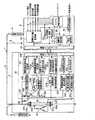
まず、図1を参照して具体的構成について説明する。図1に示すように、車両用バッテリ充電装置1(バッテリ充電装置)は、外部制御装置2と、車両用発電機3(発電機)と、充電線4とから構成されている。車両用発電機3には充電線4を介してバッテリ5が接続され、バッテリ5には電気負荷6が接続されている。さらに、車両発電機3には、充電線4を介さずに電気負荷7が直接接続されている。 First, a specific configuration will be described with reference to FIG. As shown in FIG. 1, the vehicle battery charging device 1 (battery charging device) includes an
外部制御装置2は、車両用発電機3を制御するための複数の目標指令値を決定する装置である。また、車両用発電機3をバッテリ5に接続する充電線4の断線を検出するとともに、車両用発電機3の異常を検出して保護、警告する装置でもある。外部制御装置2は、目標指令値設定部20と、通信インタフェース21と、稼働率設定部22と、充電線断線判定部23(充電線断線検出手段、保護手段)と、警告設定部24と、警告制御回路25(警告手段)と、エンジン制御回路26とから構成されている。 The
目標指令値設定部20は、各種センサ等によって得られる、バッテリ5の電圧、エンジンの回転数、車両の走行状態、及び電気負荷6、7の負荷状態などの特性値と、あらかじめ設定されている基準値との比較結果及び充電線の断線の有無に基づいて、車両用発電機3を制御するための複数の目標指令値を決定する。ここで、目標指令値は、車両用発電機3の出力する直流電圧を決定する調整電圧指令値、後述する車両用発電機3の励磁巻線30に流す励磁電流を決定する励磁電流指令値、励磁電流を制御するスイッチング動作のデューティを制限する制限デューティ指令値及び励磁電流を徐変する時間を決定する徐励制御時間指令値がある。目標指令値設定部20は、複数の目標指令値を通信に対応した情報コードに変換し、通信インタフェース21に設定する。また、調整電圧指令値と制限デューティ指令値を充電線断線判定部23に設定する。さらに、複数の目標指令値をエンジン制御装置26に設定する。 The target command
通信インタフェース21は、目標指令値設定部20によって設定された複数の目標指令値の情報コードを発電制御装置33に送信する。また、外部制御装置2からの要求に応じて、発電制御装置33の送信した情報コードを受信して、稼働率設定部22と警告設定部24に出力する。 The
稼働率設定部22は、通信インタフェース21の受信した情報コードから車両用発電機3の稼働率を抽出し、充電線断線判定部23とエンジン制御回路26に設定する。 The operating
充電線断線判定部23は、目標指令値設定部20によって設定された調整電圧指令値及び制限デューティ指令値、バッテリ5の電圧、稼働率設定部22によって設定された稼働率、あらかじめ設定されている許容電圧降下値及び許容デューティ値に基づいて、充電線4の断線の有無を判定する。 The charge line
警告設定部24は、通信インタフェース21の受信した情報コードから車両用発電機3の異常の有無を抽出し、警告制御回路25に設定する。 The
警告制御回路25は、警告設定部24によって設定された車両用発電機3の異常の有無に基づいて、車両用バッテリ充電装置1を保護するとともに、警告装置(図略)に警告信号を出力する。 The
エンジン制御部26は、各種センサ等によって得られる、バッテリ5の電圧、エンジンの回転数、車両の走行状態、及び電気負荷6、7の負荷状態などの特性値と、目標指令値設定部20によって設定された複数の目標指令値、稼働率設定部22によって設定された稼働率に基づいて、エンジンを制御する。 The
車両用発電機3は、外部制御装置2の複数の目標指令値に基づいて制御されることで、安定して直流電圧を出力し、バッテリ5を充電し電気負荷6への電力供給をするとともに、直接接続された電気負荷7に直流電圧を供給する装置である。車両用発電機3は、励磁巻線30と、電機子巻線31と、整流器32と、発電制御装置33とから構成されている。 The vehicle generator 3 is controlled based on a plurality of target command values of the
励磁巻線30は、エンジンの駆動力によって回転する回転子(図略)に巻回された巻線である。励磁巻線30は、電圧が印加されて励磁電流が流れることで磁束を発生する。励磁巻線30の一端は充電線4を介してバッテリ5と発電制御装置33に、他端は発電制御装置33にそれぞれ接続されている。 The excitation winding 30 is a winding wound around a rotor (not shown) that is rotated by the driving force of the engine. The excitation winding 30 generates a magnetic flux when a voltage is applied and an excitation current flows. One end of the excitation winding 30 is connected to the battery 5 and the power
電機子巻線31は、電機子鉄心(図略)に巻回された三相巻線である。電機子巻線31は、励磁巻線30の発生する磁束と鎖交することで三相交流電圧を発生する。 The armature winding 31 is a three-phase winding wound around an armature core (not shown). The armature winding 31 generates a three-phase AC voltage by interlinking with the magnetic flux generated by the excitation winding 30.
整流器32は、電機子巻線31の発生した三相交流電圧を三相全波整流して、直流電圧に変換する回路である。整流器32は、6つのダイオード32a〜32fを三相ブリッジ接続して構成されている。3相ブリッジの上側の3つのダイオード32a〜32cのカソードは充電線4を介してバッテリ5に接続され、下側の3つのダイオード32d〜32fのアノードは車体に接地されている。 The
発電制御装置33は、外部制御装置2の目標指令値に基づいて、励磁巻線30を流れる励磁電流を制御することで、車両用発電機3の出力する直流電圧を制御する装置である。発電制御装置33は、通信インタフェース330と、目標指令値設定部331と、電圧制御回路332と、電流制御回路333と、AND回路334と、トランジスタ335と、励磁電流検出用抵抗336と、還流ダイオード337と、発電機稼働率検出回路338と、稼働率設定部339と、異常検出回路340と、発電検出回路341と、警告設定部342とから構成されている。 The power
通信インタフェース330は、外部制御装置2の送信した情報コードを受信して、目標指令値設定部331に出力する。また、外部制御装置2からの要求に応じて、稼働率設定部339や警告設定部342によって変換され設定された発電機の稼働率や車両用発電装置3の異常の有無に関する情報コードを外部制御装置2に送信する。 The
目標指令値設定部331は、通信インタフェース330の受信した情報コードから目標指令値を抽出し設定する。目標指令値設定部331は、調整電圧指令値設定部331aと、励磁電流指令値設定部331bと、制限デューティ指令値設定部331cと、徐励制御時間指令値設定部331dとから構成されている。 The target command
調整電圧指令値設定部331aは、通信インタフェース330の受信した情報コードから調整電圧指令値を抽出し、電圧に変換する。励磁電流指令値設定部331bは、通信インタフェース330の受信した情報コードから励磁電流指令値を抽出し、電流制御回路333に設定する。制限デューティ指令値設定部331cは、通信インタフェース330の受信した情報コードから制限デューティ指令値を抽出し、電流制御回路333に設定する。徐励制御時間指令値設定部331dは、通信インタフェース330の受信した情報コードから徐励制御時間指令値を抽出し、電流制御回路333に設定する。 The adjustment voltage command
電圧制御回路332は、調整電圧指令値設定部331aによって設定された調整電圧指令値と車両用発電機3の出力する直流電圧に基づいて、励磁電流を制御するための電圧制御信号を出力する回路である。電圧制御回路332の入力端子は充電線4と整流器32の接続点に、出力端子はAND回路334にそれぞれ接続されている。 The
電流制御回路333は、励磁電流指令値設定部331b、制限デューティ指令値設定部331c及び徐励制御時間指令値設定部331dによって設定された励磁電流指令値、制限デューティ指令値、徐励制御時間指令値、励磁巻線30に流れている励磁電流及び励磁電流を制御しているトランジスタ335のスイッチング状態に基づいて、励磁電流を制御するための電流制御信号を出力する回路である。電流制御回路333は、励磁電流制限回路333aと、徐励制御回路333bと、OR回路333cとから構成されている。 The
励磁電流制限回路333aは、励磁電流指令値、制限デューティ指令値及び励磁巻線30に流れている励磁電流に基づいて、励磁電流を制限するための励磁電流制限信号を出力する回路である。励磁電流制限回路333aの入力端子は、後述するトランジスタ335と励磁電流検出用抵抗336の接続点に、出力端子はOR回路333cにそれぞれ接続されている。 The excitation
徐励制御回路333bは、徐励制御時間指令値と励磁電流を制御しているトランジスタ335のスイッチング状態に基づいて、励磁電流を徐変させるための徐励制御信号を出力する回路である。徐励制御回路333bの入力端子は、後述する励磁巻線30とトランジスタ335の接続点に、出力端子はOR回路333cにそれぞれ接続されている。 The gradual
OR回路333cは、励磁電流制限回路333aの出力する励磁電流制限信号と、徐励制御回路333bの出力する徐励制御信号の論理和をとって、励磁電流を制御するための電流制御信号を生成する回路である。OR回路333cの入力端子は励磁電流制限回路333aと徐励制御回路333bの出力端子に、出力端子はAND回路334にそれぞれ接続されている。 The OR circuit 333c generates a current control signal for controlling the excitation current by taking the logical sum of the excitation current limit signal output from the excitation
AND回路334は、電圧制御回路332の出力する電圧制御信号と、電流制御回路333の出力する電流制御信号の論理積をとって、励磁電流を制御するためのトランジスタ335のスイッチング信号を出力する回路である。AND回路334の入力端子は電圧制御回路332と電流制御回路333の出力端子に、出力端子はトランジスタ335にそれぞれ接続されている。 The AND
トランジスタ335は、AND回路334の出力するスイッチング信号に基づいてスイッチングすることで、励磁電流を制御する素子である。トランジスタ335のベースはAND回路334の出力端子に、コレクタは励磁巻線30の他端にそれぞれ接続され、エミッタは励磁電流検出用抵抗336を介して車体に接地されている。トランジスタ335と励磁巻線30の接続点は徐励制御回路333bと発電機稼働率検出回路338にそれぞれ接続されている。トランジスタ335と励磁電流検出用抵抗336の接続点は励磁電流制限回路333aに接続されている。 The
還流ダイオード337は、トランジスタ335がオフしたときに励磁巻線30に発生する還流電流を流すための素子である。還流ダイオード337のカソードは励磁巻線30の一端に、アノードは励磁巻線30の他端にそれぞれ接続されている。 The free-wheeling
発電機稼働率検出回路338は、車両用発電機3の稼働率に相当するトランジスタ335のデューティ値を検出する回路である。ここで、車両用発電機3の稼働率は、車両用発電機3の出力可能な最大電力に対する出力電力の比率である。また、励磁巻線30に流すことが可能な最大励磁電流に対する励磁電流の比率でもある。トランジスタ335のデューティ値は、トランジスタ335がスイッチングしているときのオン時間の比率である。トランジスタ335が常時オン状態のとき、デューティ値は100%であり、トランジスタ335は最大励磁電流を供給する。トランジスタ335が常時オフ状態のとき、デューティ値は0%であり、トランジスタ335は励磁電流を遮断する。そのため、トランジスタ335のデューティ値は、最大励磁電流に対する励磁電流の比率、つまり、励磁電流の導通率であり、車両用発電機3の稼働率と等価である。発電機稼働率検出回路338は、A/D変換回路を用いることなく、カウンタ等の簡素なデジタル回路で構成されている。例えば、トランジスタ335がスイッチングしているときのスイッチング周期とオン時間をそれぞれカウンタで計測し、オン時間の比率を演算してデューティ値を得てもよい。また、スイッチング周期が一定であれば、オン時間をカウンタで計測してデューティ値を得てもよい。発電機稼働率検出回路338の入力端子はトランジスタ335と励磁巻線30の接続点に接続されている。 The generator operating
稼働率設定部339は、発電機稼働率検出回路338の検出した車両用発電機3の稼働率に相当するトランジスタ335のデューティ値を通信に対応した情報コードに変換し、通信インタフェース330に設定する。 The operation
異常検出回路340は、発電制御装置33の異常の有無を検出する回路である。発電検出回路341は、電機子巻線31の出力する交流電圧に基づいて、励磁巻線30や電機子巻線31の異常の有無を検出する回路である。発電検出回路341の入力端子は電機子巻線31の接続されているダイオード32cとダイオード32fの接続点に接続されている。 The
警告設定部342は、異常検出回路340と発電検出回路341の検出した異常の有無を通信に対応した情報コードに変換し、通信インタフェース330に設定する。 The
次に、図1と図2を参照して具体的動作について説明する。車両のイグニッションスイッチがオンされると、エンジンが始動するとともに、外部制御装置2が車両用発電機3の制御を開始する。 Next, a specific operation will be described with reference to FIGS. When the ignition switch of the vehicle is turned on, the engine starts and the
図1に示すように、外部制御装置2の目標指令値設定部20は、各種センサ等によって得られる特性値と、あらかじめ設定されている基準値との比較結果に基づいて、調整電圧指令値、励磁電流指令値、制限デューティ指令値及び徐励制御時間指令値を決定する。調整電圧指令値、励磁電流指令値、制限デューティ指令値及び徐励制御時間指令値は、通信に対応した情報コードに変換され、通信インタフェース21に設定される。 As shown in FIG. 1, the target command
通信インタフェースは21は、目標指令値設定部20によって設定された調整電圧指令値、励磁電流指令値、制限デューティ指令値及び徐励制御時間指令値を発電制御装置33に送信する。 The
発電制御装置33の通信インタフェース330は、通信インタフェース21の送信した情報コードを受信して、調整電圧指令値設定部331a、励磁電流指令値設定部331b、制限デューティ指令値設定部331c及び徐励制御時間指令値設定部331dに出力する。 The
調整電圧指令値設定部331aは、通信インタフェース330の受信した情報コードから調整電圧指令値を抽出し、電圧制御回路332に設定する。励磁電流指令値設定部331bは、通信インタフェース330の受信した情報コードから励磁電流指令値を抽出し、電流制御回路333に設定する。制限デューティ指令値設定部331cは、通信インタフェース330の受信した情報コードから制限デューティ指令値を抽出し、電流制御回路333に設定する。徐励制御時間指令値設定部331dは、通信インタフェース330の受信した情報コードから徐励制御時間指令値を抽出し、電流制御回路333に設定する。 The adjustment voltage command
電圧制御回路332は、調整電圧指令値設定部331aによって設定された調整電圧指令値と車両用発電機3の出力する直流電圧に基づいて、励磁電流を制御するための電圧制御信号を出力する。 The
電流制御回路333は、励磁電流指令値、制限デューティ指令値、徐励制御時間指令値、励磁巻線30に流れている励磁電流及び励磁電流を制御しているトランジスタ335のスイッチング状態に基づいて、励磁電流を制御するための電流制御信号を出力する。電圧制御信号と電流制御信号はAND回路334に入力される。 The
AND回路334は、電圧制御信号と電流制御信号の論理積をとって、励磁電流を制御するためのトランジスタ335のスイッチング信号を出力する。スイッチング信号はトランジスタ335のベースに入力される。 The AND
トランジスタ335は、AND回路334の出力するスイッチング信号に基づいてスイッチングすることで、励磁電流を制御する。これにより、車両用発電機3は、調整電圧指令値によって決定される直流電圧を安定して出力する。 The
これに対し、車両用発電機3は、自己の状態に関する情報を外部制御装置2に送信する。発電制御装置33の発電機稼働率検出回路338は、車両用発電機3の稼働率に相当するトランジスタ335のデューティ値を検出する。発電機稼働率検出回路338の検出した車両用発電機3の稼働率に相当するトランジスタ335のデューティ値は、稼働率設定部339で通信に対応した情報コードに変換され、通信インタフェース330に設定される。 On the other hand, the vehicle generator 3 transmits information related to its own state to the
異常検出回路340は、発電制御装置33の異常の有無を検出する。また、発電検出回路341は、電機子巻線31の出力する交流電圧に基づいて、励磁巻線30や電機子巻線31の異常の有無を検出する。異常検出回路340と発電検出回路341の検出した異常の有無は、警告設定部342で通信に対応した警告情報コードに変換され、通信インタフェース330に設定される。 The
通信インタフェース330は、稼働率設定部339と警告設定部342によって設定された車両用発電機3の稼働率に相当するトランジスタ335のデューティ値と車両用発電機3の異常の有無を外部制御装置2に送信する。 The
外部制御装置2の通信インタフェース21は、通信インタフェース330の送信した情報コードを受信して稼働率設定部22と警告設定部24に出力する。 The
稼働率設定部22は、通信インタフェース21の受信した情報コードから車両用発電機3の稼働率に相当するトランジスタ335のデューティ値を抽出し、充電線断線判定部23とエンジン制御回路26に設定する。 The operating
警告設定部24は、通信インタフェース21の受信した情報コードから車両用発電機3の異常の有無を抽出し、警告制御回路25に設定する。 The
充電線断線判定部23は、目標指令値設定部20によって設定された調整電圧指令値及び制限デューティ指令値、バッテリ5の電圧、稼働率設定部22によって設定された車両用発電機3の稼働率に相当するトランジスタ335のデューティ値、あらかじめ設定されている許容電圧降下値及び許容デューティ値に基づいて、充電線4の断線の有無を判定する。 The charge line
エンジン制御部26は、各種センサ等によって得られる、バッテリ5の電圧、エンジンの回転数、車両の走行状態、及び電気負荷6、7の負荷状態などの特性値と、目標指令値設定部20によって設定された複数の目標指令値、稼働率設定部22によって設定された稼働率に基づいて、エンジンを制御する。 The
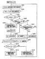
ここで、外部制御装置2の充電線断線判定部23における充電線4の断線検出方法について具体的に説明する。図2に示すように、充電線断線判定部23は、調整電圧指令値VREGに、目標指令値設定部20の決定した調整電圧指令値を設定する。また、制限デューティ指令値Dに、目標指令値設定部20の決定した制限デューティ指令値を設定する(S101)。 Here, a method for detecting disconnection of the charging line 4 in the charging line
その後、充電線断線判定部23は、バッテリ電圧値VSに、検出したバッテリ5の電圧値を設定する。また、制御デューティ値Fdutyに、稼働率設定部22の抽出した車両用発電機3の稼働率に相当するトランジスタ335のデューティ値を設定する(S102)。 Thereafter, the charge line
その後、充電線断線判定部23は、ステップS102で入力されたバッテリ電圧値VSを、ステップS101で設定された調整電圧指令値VREGからあらかじめ設定されている許容電圧降下値ΔVを減じた値(所定電圧閾値)と比較する。ここで、許容電圧降下値ΔVは、充電線4に車両用発電機3からバッテリ5に向かって電流が流れることで発生する電圧降下の許容値(例えば1.5V)を示すものである。また、ステップS102で設定された制御デューティ値Fdutyを、ステップS101で設定された制限デューティ指令値Dからあらかじめ設定されている許容デューティ値Δdを減じた値(所定稼働率閾値)と比較する。ここで、許容デューティ値Δdは、比較の際に許容することができるデューティの許容値(例えば5%)を示すものである(S103)。 Thereafter, the charge line
ステップS103において、バッテリ電圧値VSが調整電圧指令値VREGから許容電圧降下値ΔVを減じた値未満、かつ、制御デューティ値Fdutyが制限デューティ指令値Dから許容デューティ値Δdを減じた値未満(VS<VREG−ΔV、かつ、Fduty<D−Δd)である場合、バッテリ5の電圧が低下しているにもかかわらず、車両用発電機3の稼働率が低下、つまり、車両用発電機3の電気的負荷が軽くなっていることから、充電線断線判定部23は、充電線4が断線していると判定する。充電線4が断線していると判定されると、目標指令値設定部20は、車両用発電機3及び電気負荷7を保護するため、調整電圧指令値を所定電圧(例えば、バッテリ5の開放電圧より高く、車両用発電機3及び電気負荷6、7の最大許容電圧以下である14.5V)に設定する。また、警告制御回路25は、警告装置を介して充電線4の断線を運転者に警告する(S104)。 In step S103, the battery voltage value VS is less than the value obtained by subtracting the allowable voltage drop value ΔV from the adjustment voltage command value VREG, and the control duty value Fduty is less than the value obtained by subtracting the allowable duty value Δd from the limit duty command value D (VS When <VREG−ΔV and Fduty <D−Δd), the operating rate of the vehicle generator 3 is reduced despite the voltage of the battery 5 being reduced, that is, the vehicle generator 3 Since the electrical load is lighter, the charging line
これに対し、ステップS103において、バッテリ電圧値VSが調整電圧指令値VREGから許容電圧降下値ΔVを減じた値未満であるが、制御デューティ値Fdutyが制限デューティ指令値から許容デューティ値Δdを減じた値以上(VS<VREG−ΔVであるが、Fduty≧D−Δd)である場合、バッテリ5の電圧の低下にともなって、車両用発電機3の稼働率が上昇、つまり、車両用発電機3の電気的負荷が重くなっていることから、充電線断線判定部23は、充電線4が断線していないと判定する。充電線4が断線していないと判定されると、目標指令値設定部20は、車両用発電機3の保護を解除し、通常通り調整電圧指令値を決定する。また、警告制御回路25は、警告装置を介して出される充電線4の断線の警告を解除する。(S105)。 On the other hand, in step S103, the battery voltage value VS is less than the value obtained by subtracting the allowable voltage drop value ΔV from the adjustment voltage command value VREG, but the control duty value Fduty is obtained by subtracting the allowable duty value Δd from the limit duty command value. When the value is equal to or greater than (VS <VREG−ΔV, but Fduty ≧ D−Δd), the operating rate of the vehicle generator 3 increases as the voltage of the battery 5 decreases, that is, the vehicle generator 3 Since the electrical load is heavy, the charging line
さらに、調整電圧指令値が14.5V、制限デューティ指令値が100%の状態で、外部制御装置2が車両用発電機3を制御している場合について説明する。充電線4が断線した場合、バッテリ5は、車両用発電機3によって充電されない。そのため、バッテリ5の電圧は、例えば、12V程度にまで低下する。また、充電線4が断線したことで車両用発電機3の電気的負荷が軽くなり、稼働率が低下する。車両発電機3の稼働率の低下にともない、トランジスタ335のデューティ値も、例えば、7%程度に低下する。このとき、ステップS103において、VS<VREG−ΔV(12V<14.5V−1.5V)かつ、Fduty<D−Δd(7%<100%−5%)となり、充電線断線判定部23は、充電線4が断線していると判定する。 Furthermore, the case where the
ここでは、充電線4が断線した場合、トランジスタ335のデューティ値が7%程度に低下する例を挙げているが、車両用発電機3が高回転で駆動されている場合、デューティ値はさらに低下する。また、車両用発電機3に充電線4を介さずに直接接続される電気負荷7がある場合、デューティ値は増加するが、それでも数10%程度であり、充電線4の断線を誤判定することはない。 In this example, when the charging line 4 is disconnected, the duty value of the
これに対して、充電線4が断線していない場合、電気負荷6、7の消費電力が増加すると、バッテリ5の電圧は、例えば、12V程度にまで低下する。バッテリ5の電圧が低下することで車両用発電機3の電気的負荷が重くなり、稼働率が上昇する。車両用発電機3の稼働率の上昇にともない、トランジスタ335のデューティ値も上昇し、100%になる。このとき、ステップS103において、VS<VREG−ΔV(12V<14.5V−1.5V)であるが、Fduty>D−Δd(100%>100%−5%)となり、充電線断線判定部23は、充電線4が断線していないと判定する。 On the other hand, when the charging line 4 is not disconnected and the power consumption of the electric loads 6 and 7 increases, the voltage of the battery 5 decreases to, for example, about 12V. When the voltage of the battery 5 decreases, the electrical load of the vehicle generator 3 increases, and the operating rate increases. As the operating rate of the vehicular generator 3 increases, the duty value of the
ここでは、電気負荷6、7の消費電力の増加にともない、バッテリ5の電圧が12V程度にまで低下する例を挙げているが、電気負荷6、7の消費電力が車両用発電機3の発電電力の範囲内であれば、バッテリ電圧の低下は抑えられ、調整電圧指令値VREGから許容電圧降下値ΔVを減じた値より小さくなることはない。 In this example, as the power consumption of the electric loads 6 and 7 increases, the voltage of the battery 5 decreases to about 12 V. However, the power consumption of the electric loads 6 and 7 is generated by the vehicle generator 3. If it is within the range of electric power, the battery voltage drop is suppressed, and it does not become smaller than the value obtained by subtracting the allowable voltage drop value ΔV from the adjustment voltage command value VREG.
最後に具体的効果について説明する。第1実施形態によれば、外部制御装置2と車両用発電機3との間で通信インタフェース21、330を介して送受信される複数の指令値に基づいて制御される車両用バッテリ充電装置1において、バッテリ電圧値VSが調整電圧指令値VREGから許容電圧降下値ΔVを減じた値より小さく、かつ、制御デューティ値Fdutyが制限デューティ指令値Dから許容デューティ値Δdを減じた値より小さいとき、充電線4が断線していると判定することができる。そのため、従来のように、車両用発電機3の出力電圧とバッテリ5の電圧の電圧差に基づいて充電線4の断線を判定する場合に必要とされるA/D変換回路が不要であり、簡素な構成で充電線4の断線を検出することができる。 Finally, specific effects will be described. According to the first embodiment, in the vehicle
第1実施形態によれば、制御デューティ値Fdutyを制限デューティ指令値Dより許容デューティ値Δdだけ小さい値と比較することができる。そのため、励磁電流を制御するスイッチング動作のデューティが制限されている場合においても、誤判定することなく、充電線4の断線を確実に判定することができる。 According to the first embodiment, the control duty value Fduty can be compared with a value smaller than the limit duty command value D by the allowable duty value Δd. Therefore, even when the duty of the switching operation for controlling the excitation current is limited, the disconnection of the charging line 4 can be reliably determined without erroneous determination.
第1実施形態によれば、励磁電流の導通率であるトランジスタ335のデューティ値により、車両発電機3の稼働率を容易に知ることができる。 According to the first embodiment, the operating rate of the vehicle generator 3 can be easily known from the duty value of the
また、第1実施形態によれば、充電線4が断線していると判定したとき、調整電圧指令値を所定電圧にするとともに、充電線4の断線を警告することができる。そのため、車両用発電機3や、車両用発電機3に充電線4を介さず直接接続された電気負荷7を保護するとともに、電気負荷7に電力を供給することができる。また、充電線4の断線を運転者に警告することができる。 Further, according to the first embodiment, when it is determined that the charging line 4 is disconnected, the adjustment voltage command value can be set to a predetermined voltage, and a disconnection of the charging line 4 can be warned. Therefore, it is possible to protect the electric generator 7 for the vehicle and the electric load 7 that is directly connected to the electric generator 3 for the vehicle without using the charging line 4, and supply electric power to the electric load 7. In addition, the driver can be warned of the disconnection of the charging line 4.
さらに、第1実施形態によれば、充電線4が断線していると判定したとき、調整電圧指令値を、バッテリ5の開放電圧より高く、車両用発電機3及び車両用発電機3に充電線4を介さず直接接続されている電気負荷7の最大許容電圧以下にすることができる。そのため、充電線4が断線していると判定した後も、継続して、充電線4の断線を判定し続けることができる。また、車両用発電機4や電気負荷7を保護し続けることができる。さらに、充電線4の断線を運転者に警告し続けることができる。 Furthermore, according to the first embodiment, when it is determined that the charging wire 4 is disconnected, the adjustment voltage command value is higher than the open voltage of the battery 5 and the vehicle generator 3 and the vehicle generator 3 are charged. The maximum allowable voltage of the electrical load 7 connected directly without going through the line 4 can be reduced. Therefore, even after it is determined that the charging line 4 is disconnected, the disconnection of the charging line 4 can be continuously determined. Further, the vehicle generator 4 and the electric load 7 can be continuously protected. Furthermore, it is possible to continue warning the driver about the disconnection of the charging line 4.
(第2実施形態)
次に第2実施形態における充電線の断線検出に関するフローチャートを図3に示す。ここでは、第1実施形態における車両用バッテリ充電装置との相違部分である断線検出方法についてのみ説明し、共通する部分については、必要とされる箇所以外説明を省略する。なお、前記実施形態と同一の要素には同一の符号を付して説明する。回路構成は、第1実施形態の車両用バッテリ充電装置と全く同一であるので省略する。(Second Embodiment)
Next, the flowchart regarding the disconnection detection of the charge wire in 2nd Embodiment is shown in FIG. Here, only the disconnection detection method that is different from the vehicle battery charging device in the first embodiment will be described, and the description of the common portions other than the necessary portions will be omitted. In addition, the same code | symbol is attached | subjected and demonstrated to the element same as the said embodiment. Since the circuit configuration is exactly the same as that of the vehicle battery charging device of the first embodiment, a description thereof will be omitted.
まず図3を参照して、外部制御装置2の充電線断線判定部23における、充電線4の断線検出方法について具体的に説明する。図3に示すように、充電線断線判定部23は、調整電圧指令値VREGに、目標指令値設定部20の決定した調整電圧指令値を設定する(S201)。その後、充電線断線判定部23は、バッテリ電圧値VSに、検出したバッテリ5の電圧値を設定する(S202)。 First, referring to FIG. 3, a method for detecting disconnection of the charging line 4 in the charging line
その後、充電線断線判定部23は、ステップS202で入力されたバッテリ電圧値VSを、ステップS201で設定された調整電圧指令値VREGからあらかじめ設定されている許容電圧降下値ΔVを減じた値と比較する(S203)。 Thereafter, the charge line
ステップS203において、バッテリ電圧値VSが調整電圧指令値VREGから許容電圧降下値ΔVを減じた値以上(VS≧VREG−ΔV)である場合、バッテリ5の電圧低下量が小さいため、充電線断線判定部23は、充電線4が断線していないと判定する。充電線4が断線していないと判定されると、目標指令値設定部20は、車両用発電機3の保護を解除し、通常通り調整電圧指令値を決定する。また、警告制御回路25は、警告装置を介して出される充電線4の断線の警告を解除し、次のステップに進む(S204)。 In step S203, if the battery voltage value VS is equal to or greater than the value obtained by subtracting the allowable voltage drop value ΔV from the adjustment voltage command value VREG (VS ≧ VREG−ΔV), the voltage drop amount of the battery 5 is small. The
これに対し、ステップS203において、バッテリ電圧値VSが調整電圧指令値VREGから許容電圧降下値ΔVを減じた値未満(VS<VREG−ΔV)である場合、充電線断線判定部23は、目標指令値設定部20によって制限デューティ指令値が設定されているか判定する(S205)。 On the other hand, when the battery voltage value VS is less than the value obtained by subtracting the allowable voltage drop value ΔV from the adjustment voltage command value VREG (VS <VREG−ΔV) in step S203, the charging line
ステップS205において、制限デューティ指令値が設定されていない場合、目標指令値設定部20は、制限デューティ指令値Dに100%の制限デューティ指令値を設定する(S206)。 In step S205, when the limit duty command value is not set, the target command
これに対し、ステップS205において、制限デューティ指令値が設定されている場合、制限デューティ指令値に基づいて充電線4の断線の判定を実施するか判定する。
(S207)。On the other hand, if the limited duty command value is set in step S205, it is determined whether to determine whether the charging line 4 is disconnected based on the limited duty command value.
(S207).
ステップS207において、エンジンの負荷を軽減する目的等で一時的に設定された制限デューティ指令値でなく、充電線4の断線の判定を実施する場合、目標指令値設定部20は、制限デューティ指令値Dに目標指令値設定部20の決定した制限デューティ指令値を設定する(S208)。 In step S207, when the determination of disconnection of the charging line 4 is performed instead of the limited duty command value temporarily set for the purpose of reducing the engine load, the target command
これに対し、ステップS207において、エンジンの負荷を軽減する目的等で一時的に設定された制限デューティ指令値であり、誤判定する可能性があるため、充電線4の断線の判定を実施しない場合、ステップS201に戻る。 On the other hand, in step S207, it is a limited duty command value temporarily set for the purpose of reducing the load on the engine or the like, and there is a possibility of erroneous determination. Return to step S201.
ステップS206又はS208において、制限デューティ指令値Dが設定されると、充電線断線判定部23は、制御デューティ値Fdutyに、稼働率設定部22の抽出した車両用発電機3の稼働率に相当するトランジスタ335のデューティ値を設定する(S209)。 When the limited duty command value D is set in step S206 or S208, the charging line
その後、充電線断線判定部23は、ステップS209で設定された制御デューティ値Fdutyを、ステップS206又はS208で設定された制限デューティ指令値Dからあらかじめ設定されている許容デューティ値Δdを減じた値と比較する(S210)。 Thereafter, the charging line
ステップS210において、制御デューティ値Fdutyが制限デューティ指令値Dから許容デューティ値Δdを減じた値未満(Fduty<D−Δd)である場合、充電線断線判定部23は、充電線4が断線していると判定する。充電線4が断線していると判定されると、目標指令値設定部20は、車両用発電機3を保護するため、調整電圧指令値を所定電圧(例えば、バッテリ5の開放電圧より高く、車両用発電機3及び電気負荷6、7の最大許容電圧以下である14.5V)に設定する。また、警告制御回路25は、警告装置を介して充電線4の断線を運転者に警告し、ステップS201に戻る(S211)。 In step S210, when the control duty value Fduty is less than the value obtained by subtracting the allowable duty value Δd from the limit duty command value D (Fduty <D−Δd), the charging line
これに対し、ステップS210において、制御デューティ値Fdutyが制限デューティ指令値Dから許容デューティ値Δdを減じた値以上(Fduty≧D−Δd)である場合、充電線断線判定部23は、充電線4が断線していないと判定する。充電線4が断線していないと判定されると、目標指令値設定部20は、車両用発電機3の保護を解除し、通常通り調整電圧指令値を決定する。また、警告制御回路25は、警告装置を介して出されている充電線4の断線の警告を解除し、ステップS201に戻る(S212)。 On the other hand, when the control duty value Fduty is equal to or greater than the value obtained by subtracting the allowable duty value Δd from the limit duty command value D in step S210 (Fduty ≧ D−Δd), the charging line
さらに、調整電圧指令値が14.5Vの状態で、外部制御装置2が車両用発電機3を制御している場合について説明する。充電線4が断線していない場合、バッテリ5の電圧は、例えば、14V程度に保たれている。このとき、ステップS203において、VS>VREG−ΔV(14V>14.5V−1.5V)となり、充電線断線判定部23は、充電線4が断線していないと判定する。 Furthermore, a case where the
これに対し、充電線4が断線、又は、電気負荷6、7の消費電力が増加した場合、バッテリ5の電圧が、例えば、12V程度にまで低下する。このとき、ステップS203において、VS<VREG−ΔV(12V<14.5V−1.5V)となり、ステップS205において、制限デューティ指令値が設定されているか判定する。 On the other hand, when the charging line 4 is disconnected or the power consumption of the electric loads 6 and 7 is increased, the voltage of the battery 5 is reduced to, for example, about 12V. At this time, in step S203, VS <VREG−ΔV (12V <14.5V−1.5V) is established, and in step S205, it is determined whether the limited duty command value is set.
制御デューティ指令値が設定されていない場合、制御デューティ指令値に100%を設定し、第1実施形態の場合と同様に充電線4の断線を判定する。 When the control duty command value is not set, 100% is set to the control duty command value, and disconnection of the charging line 4 is determined in the same manner as in the first embodiment.
これに対し、制御デューティ指令値が設定されている場合、ステップS207において、制御デューティ指令値に基づいて、充電線4の断線の判定を実施するか判定する。 On the other hand, when the control duty command value is set, in step S207, it is determined whether or not to determine the disconnection of the charging line 4 based on the control duty command value.
制御デューティ指令値がエンジンの負荷を軽減する目的等で一時的に設定されたものである場合、充電線4の断線の判定を実施せず、誤判定を防止する。さらに、保護や警告の誤動作をも防止する。ここで、エンジンの負荷を軽減する目的等で一時的に制限デューティ指令値を設定した場合、充電線4が断線していないにもかかわらず断線していると誤判定する可能性がある。 When the control duty command value is temporarily set for the purpose of reducing the load on the engine or the like, the determination of disconnection of the charging line 4 is not performed, and erroneous determination is prevented. In addition, protection and warning malfunctions are prevented. Here, when the limit duty command value is temporarily set for the purpose of reducing the load on the engine or the like, there is a possibility of erroneous determination that the charging line 4 is disconnected even though the charging line 4 is not disconnected.
これに対し、制御デューティ指令値がエンジンの負荷を軽減する目的等で一時的に設定されたものでなく、車両用発電機3の発電電力を常時制限する目的等で設定されたものである場合、充電線4の断線の判定を実施する。 On the other hand, when the control duty command value is not temporarily set for the purpose of reducing the engine load or the like, but is set for the purpose of constantly limiting the power generated by the vehicle generator 3 or the like. Then, the disconnection of the charging line 4 is determined.
設定されている制限デューティ指令値が、例えば、70%であると、充電線4が断線した場合、ステップS210において、Fduty<D−Δd(7%<70%−5%)となり、充電線断線判定部23は、充電線4が断線していると判定する。 If the set duty limit command value is 70%, for example, when the charging line 4 is disconnected, Fduty <D−Δd (7% <70% −5%) in step S210, and the charging line is disconnected. The
これに対して、電気負荷6、7の消費電力の増加した場合、ステップS210において、Fduty>D−Δd(70%>70%−5%)となり、充電線断線判定部23は、充電線4が断線していないと判定する。 On the other hand, when the power consumption of the electric loads 6 and 7 increases, in step S210, Fduty> D−Δd (70%> 70% −5%), and the charging line
最後に具体的効果について説明する。第2実施形態によれば、バッテリ電圧値VSを調整電圧指令値VREGから許容電圧降下値ΔVを減じた値と比較した後に、制御デューティ値Fdutyを制限デューティ指令値Dから許容デューティ値Δdを減じた値と比較することができる。そのため、バッテリ電圧値VSが調整電圧指令値VREGから許容電圧降下値ΔVを減じた値以上のとき、制御デューティ値Fdutyを比較する必要がなくなり、判定のための処理時間を短縮することができる。 Finally, specific effects will be described. According to the second embodiment, after comparing the battery voltage value VS with the value obtained by subtracting the allowable voltage drop value ΔV from the adjustment voltage command value VREG, the control duty value Fduty is subtracted from the limit duty command value D. Can be compared. Therefore, when the battery voltage value VS is equal to or larger than the value obtained by subtracting the allowable voltage drop value ΔV from the adjustment voltage command value VREG, it is not necessary to compare the control duty value Fduty, and the processing time for determination can be shortened.
また、第2実施形態によれば、外部制御装置2が、エンジンの負荷を軽減する目的等で一時的に制限デューティ指令値を設定しているとき、充電線4の断線の判定を停止することができる。そのため、車両用発電機3の励磁電流を制御するスイッチング動作のデューティが制限されることで発生する充電線4の断線の誤判定を未然に防止することができる。 Further, according to the second embodiment, when the
(第3実施形態)
次に第3実施形態における発電制御装置の回路図を図4に示す。ここでは、第1及び第2実施形態における車両用バッテリ充電装置との相違部分である発電制御装置の電圧制御回路及び発電機稼働率検出回路と、充電線の断線検出方法についてのみ説明し、共通する部分については、必要とされる箇所以外説明を省略する。なお、第1及び第2実施形態と同一の要素には同一の符号を付して説明する。(Third embodiment)
Next, a circuit diagram of the power generation control device in the third embodiment is shown in FIG. Here, only the voltage control circuit and generator operating rate detection circuit of the power generation control device, which are different from the vehicle battery charging device in the first and second embodiments, and the disconnection detection method of the charging line will be described and shared. Description of the parts to be performed is omitted except for the necessary parts. In addition, the same code | symbol is attached | subjected and demonstrated to the element same as 1st and 2nd embodiment.
まず、図4を参照して具体的構成について説明する。電圧制御回路332は、調整電圧指令値設定部331aによって設定された調整電圧指令値及び車両用発電機3の出力する直流電圧に基づいて、励磁電流を制御するための電圧制御信号を出力する回路である。図4に示すように、電圧制御回路332は、抵抗332a、332bと、コンパレータ332cとから構成されている。抵抗332aと抵抗332bは直列接続されている。直列接続された抵抗332a、332bの内、抵抗332aの一端は充電線4と整流器32の接続点に接続され、抵抗332bの一端は車体に接地されている。コンパレータ332cの反転入力端子は抵抗332aと抵抗332bの接続点に、非反転入力端子は調整電圧指令値設定部に、出力端子はAND回路334にそれぞれ接続されている。 First, a specific configuration will be described with reference to FIG. The
発電機稼働率検出回路343は、電流制御信号によって制限される前の車両用発電機3の稼働率に相当する電圧制御信号のデューティ値を検出する回路である。ここで、トランジスタ335のスイッチング信号を出力するAND回路334は、電圧制御信号と電流制御信号の論理積をとっており、トランジスタ335のスイッチング信号は、電圧制御信号を電流制御信号で制限することで決まる。そのため、電圧制御信号のデューティ値は、電流制御信号によって制限される前の車両用発電機3の稼働率と等価である。発電機稼働率検出回路343は、A/D変換回路を用いることなく、カウンタ等の簡素なデジタル回路で構成されている。例えば、コンパレータ332cの出力信号が、ハイレベルとローレベルを繰り返すときの周期とハイレベルになっている時間をそれぞれカウンタで計測し、ハイレベルの時間比率を演算してデューティ値を得てもよい。発電機稼働率検出回路343の入力端子はコンパレータ332cとAND回路334の接続点(R点)に接続されている。 The generator operating
稼働率設定部339は、発電機稼働率検出回路343の検出した電流制御信号によって制限される前の車両用発電機3の稼働率に相当する電圧制御信号のデューティ値を通信に対応した情報コードに変換し、通信インタフェース330に設定する。 The operating
次に、図5を参照して、外部制御装置2の充電線断線判定部23における充電線4の断線検出方法について具体的に説明する。ここで、ステップS201〜S204は、第2実施形態と全く同一であるので省略する。 Next, with reference to FIG. 5, the disconnection detection method of the charge line 4 in the charge line
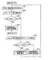
ステップS203において、バッテリ電圧値VSが調整電圧指令値VREGから許容電圧降下値ΔVを減じた値未満(VS<VREG−ΔV)である場合、充電線断線判定部23は、電圧制御デューティ値Rdutyに、稼働率設定部22の抽出した電流制御信号によって制限される前の車両用発電機3の稼働率に相当する電圧制御信号のデューティ値を設定する(S301)。 In step S203, when the battery voltage value VS is less than the value obtained by subtracting the allowable voltage drop value ΔV from the adjustment voltage command value VREG (VS <VREG−ΔV), the charging line
その後、充電線断線判定部23は、電圧制御デューティ値Rdutyが、最大励磁電流を流す場合に相当する100%であるか判定する(S302)。 Thereafter, the charging line
ステップS302において、電圧制御デューティ値Rdutyが100%でない場合、バッテリ5の電圧が低下しているにもかかわらず、発電制御装置33が励磁巻線30に最大励磁電流を流そうとしないため、充電線断線判定部23は、充電線4が断線していると判定する。充電線4が断線していると判定されると、目標指令値設定部20は、車両用発電機3を保護するため、調整電圧指令値を所定電圧(例えば、バッテリ5の開放電圧より高く、車両用発電機3及び電気負荷6、7の最大許容電圧以下である14.5V)に設定する。また、警告制御回路25は、警告装置を介して充電線4の断線を運転者に警告し、ステップS201に戻る(S303)。 In step S302, if the voltage control duty value Rduty is not 100%, the power
これに対し、ステップS302において、電圧制御デューティ値Rdutyが100%である場合、バッテリ5の電圧の低下にともなって、発電制御装置33が励磁巻線30に最大励磁電流を流そうとするため、充電線断線判定部23は、充電線4が断線していないと判定する。充電線4が断線していないと判定されると、目標指令値設定部20は、車両用発電機3の保護を解除し、通常通り調整電圧指令値を決定する。また、警告制御回路25は、警告装置を介して出されている充電線4の断線の警告を解除し、ステップS201に戻る(S304)。 On the other hand, when the voltage control duty value Rduty is 100% in step S302, the power
さらに、調整電圧指令値が14.5Vの状態で、外部制御装置2が車両用発電機3を制御している場合について説明する。充電線4が断線していない場合、バッテリ5の電圧は、例えば、14V程度に保たれている。このとき、ステップS203において、VS>VREG−ΔV(14V>14.5V−1.5V)となり、充電線断線判定部23は、充電線4が断線していないと判定する。 Furthermore, a case where the
これに対し、充電線4が断線、又は、電気負荷6、7の消費電力が増加した場合、バッテリ5の電圧が、例えば、12V程度にまで低下する。このとき、ステップS203において、VS<VREG−ΔV(12V<14.5V−1.5V)となり、ステップS301において、電圧制御信号のデューティ値を設定する。 On the other hand, when the charging line 4 is disconnected or the power consumption of the electric loads 6 and 7 is increased, the voltage of the battery 5 is reduced to, for example, about 12V. At this time, in step S203, VS <VREG−ΔV (12V <14.5V−1.5V), and in step S301, the duty value of the voltage control signal is set.
充電線4が断線した場合、車両用発電機3の電気的負荷が軽くなり、発電機制御装置33が励磁巻線30に最大励磁電流を流す必要がなくなるため、電圧制御信号のデューティ値も、例えば、7%程度に低下する。このとき、ステップS303において、Rduty<100%(7%<100%)となり、充電線断線判定部23は、充電線4が断線していると判定する。 When the charging line 4 is disconnected, the electrical load on the vehicle generator 3 is reduced, and the
これに対して、電気負荷6、7の消費電力が増加した場合、車両用発電機3の電気的負荷が重くなり、発電機制御装置33が励磁巻線30に最大励磁電流を流そうとするため、電圧制御信号のデューティ値は100%に上昇する。このとき、ステップS303において、Rduty=100%(100%=100%)となり、充電線断線判定部23は、充電線4が断線していないと判定する。 On the other hand, when the power consumption of the electric loads 6 and 7 increases, the electric load of the vehicle generator 3 becomes heavy, and the
最後に具体的効果について説明する。第3の実施形態によれば、電圧制御信号のデューティ値により、車両用発電機3の稼働率を容易に知ることができる。 Finally, specific effects will be described. According to the third embodiment, the operating rate of the vehicle generator 3 can be easily known from the duty value of the voltage control signal.
また、第3の実施形態によれば、バッテリ5の電圧が所定電圧閾値より小さく、かつ、電圧制御信号のデューティ値によって得られる車両用発電機3の稼働率が所定稼働率閾値より小さいとき、充電線4が断線している判定することができる。そのため、外部制御装置2からの車両用発電機3の稼働率を制御する指令値に対する判定を処理する必要がなくなり、プログラムの簡素化が可能となる。具体的には、バッテリ電圧値VSの判定と、電流制御信号によって制限される前の車両用発電機3の稼働率に相当する電圧制御信号のデューティ値Rdutyの判定によって、バッテリ電圧値VSが調整電圧指令値VREGから許容電圧降下値ΔVを減じた値より小さく、かつ、電圧制御信号のデューティ値Rdutyが100%でないとき、充電線4が断線していると判定することができる。そのため、外部制御装置2からの励磁電流を制限する指令(例えば、励磁電流指令値、制限デューティ指令値、徐励制御時間指令値等)に対する処理手順をなくすことができ、プログラムの簡素化が可能となる。 Further, according to the third embodiment, when the voltage of the battery 5 is smaller than a predetermined voltage threshold and the operating rate of the vehicle generator 3 obtained by the duty value of the voltage control signal is smaller than the predetermined operating rate threshold, It can be determined that the charging line 4 is disconnected. Therefore, it is not necessary to process the determination for the command value for controlling the operating rate of the vehicular generator 3 from the
なお、本発明は、上記実施形態に限定されるものではなく、本発明の要旨の範囲内において種々の変形実施が可能である。例えば、充電線断線判定部23の制限デューティ指令値を励磁電流指令値に置き換え、予め設定される許容電圧降下及び許容励磁電流に基づいて、充電線4の断線の有無を判定するようにしてもよい。 In addition, this invention is not limited to the said embodiment, A various deformation | transformation implementation is possible within the range of the summary of this invention. For example, the limit duty command value of the charging line
(第4実施形態)
第4実施形態における車両用バッテリ充電装置は、車両の燃費をよりよくするため、車両の走行状態に応じて車両用発電機の出力電圧を制御するものである。車両の加速時には、車両用発電機の出力電圧を下げ、減速時には、出力電圧を上げる。これにより、車両用発電機によるエンジン負荷を低減して、エンジンの低燃費化を図っている。なお、アイドリング時や定速走行時には、バッテリの入出力電流の時間積算値を所定の目標値に近づけるように、車両用発電機の出力電圧を調整する。(Fourth embodiment)
The vehicle battery charging device in the fourth embodiment controls the output voltage of the vehicle generator in accordance with the running state of the vehicle in order to improve the fuel efficiency of the vehicle. When the vehicle is accelerated, the output voltage of the vehicular generator is lowered, and when the vehicle is decelerated, the output voltage is raised. As a result, the engine load caused by the vehicular generator is reduced to reduce fuel consumption of the engine. When idling or traveling at a constant speed, the output voltage of the vehicle generator is adjusted so that the time integrated value of the input / output current of the battery approaches a predetermined target value.
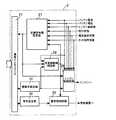
次に第4実施形態における外部制御装置の回路図を図6に、充電線の断線検出に関するフローチャートを図7に示す。第4実施形態における車両用バッテリ充電装置は、第1実施形態の車両用バッテリ充電装置に対して、さらに、バッテリ電流をも考慮して、車両用発電機を制御する構成となっている。ここでは、第1実施形態における車両用バッテリ充電装置との相違部分である外部制御装置の目標指令値設定部、充電線断線判定部、及びエンジン制御回路と、充電線の断線検出方法についてのみ説明し、共通する部分については、必要とされる箇所以外説明を省略する。なお、第1実施形態と同一の要素には同一の符号を付して説明する。 Next, FIG. 6 shows a circuit diagram of an external control device according to the fourth embodiment, and FIG. 7 shows a flowchart relating to detection of disconnection of a charging line. The vehicle battery charger in the fourth embodiment is configured to control the vehicle generator in consideration of the battery current with respect to the vehicle battery charger of the first embodiment. Here, only the target command value setting unit, the charging line disconnection determination unit, the engine control circuit, and the charging line disconnection detection method of the external control device, which are different from the vehicle battery charging device in the first embodiment, will be described. For the common parts, descriptions other than the necessary parts are omitted. In addition, the same code | symbol is attached | subjected and demonstrated to the element same as 1st Embodiment.
まず図6を参照して、外部制御装置2の構成について説明する。外部制御装置2は、目標指令値設定部27と、通信インタフェース21と、稼働率設定部22と、充電線断線判定部28(充電線断線検出手段、保護手段)と、警告設定部24と、警告制御回路25(警告手段)と、エンジン制御回路29とから構成されている。 First, the configuration of the
目標指令値設定部27は、各種センサ等によって得られる、バッテリ5の電流、電圧、エンジンの回転数、車両の走行状態、及び電気負荷6、7の負荷状態などの特性値と、あらかじめ設定されている基準値との比較結果及び充電線の断線の有無に基づいて、車両用発電機3を制御するための複数の目標指令値を決定する。目標指令値には、第1実施形態において挙げたもの以外に、車両用発電機3の出力電圧をバッテリ5の電圧より低くして、バッテリ5への充電を一時的に停止するように指示する発電停止指令値がある。目標指令値設定部27は、複数の目標指令値を通信に対応した情報コードに変換し、通信インタフェース21に設定する。また、制限デューティ指令値を充電線断線判定部28に設定する。さらに、複数の目標指令値をエンジン制御装置29に設定する。 The target command
稼働率設定部22は、通信インタフェース21の受信した情報コードから車両用発電機3の稼働率を抽出し、充電線断線判定部28とエンジン制御回路29に設定する。 The operating
充電線断線判定部28は、バッテリ5の電流、あらかじめ設定されている基準電流値、稼働率設定部22によって設定された稼働率、あらかじめ設定されているデューティ値及び許容デューティ値、及び目標指令値設定部27によって設定された制限デューティ指令値に基づいて、充電線4の断線の有無を判定する。 The charge line
エンジン制御部29は、各種センサ等によって得られる、バッテリ5の電流及び電圧、エンジンの回転数、車両の走行状態、及び電気負荷6、7の負荷状態などの特性値と、目標指令値設定部27によって設定された複数の目標指令値、稼働率設定部22によって設定された稼働率に基づいて、エンジンを制御する。 The engine control unit 29 includes characteristic values such as the current and voltage of the battery 5, the engine speed, the running state of the vehicle, and the load states of the electric loads 6 and 7, and a target command value setting unit obtained by various sensors. The engine is controlled on the basis of the plurality of target command values set by 27 and the operating rate set by the operating
次に、外部制御装置2の充電線断線判定部28における充電線4の断線検出方法について具体的に説明する。図7に示すように、充電線断線判定部28は、バッテリ5が放電状態であるか否かを判定する(S401)。具体的には、バッテリ5の電流値をあらかじめ設定されている基準電流値(例えば0A、所定電流閾値)と比較する。バッテリ5が充電状態から放電状態になると、バッテリ5に流れ込む電流は減少し、やがて、バッテリ5から電流が流れ出す。そのため、バッテリ5の電流を基準電流値と比較することで、バッテリ5の放電状態を判定することができる。充電断線判定部28は、バッテリ5の電流が基準電流値より小さい場合、バッテリ5が放電状態であると判定する。なお、電気負荷6、7の入り、切りの際に、車両用発電機3の出力電流の応答遅れで生じてしまうバッテリ電流の過渡的な放電電流や充電電流は、あらかじめフィルタ等で除去し、定常的なバッテリ電流を判定している。また、バッテリ5の充電状態が満充電状態になっているときには、バッテリ5に流れ込む電流は、わずかな充電電流となる。このようなときには、基準電流値は、0Aよりも小さい値(例えば放電電流5Aに相当する−5A)に設定されていてもよい。ところで、電流を検出する電流センサには、過渡的な応答遅れがある。そのため、バッテリ5が充電状態から放電状態になる過程で、電流が減少して0Aになっても、電流センサは0Aを出力しない。このとき、電流センサは、0Aより大きい値を出力する。このような電流センサの過渡的な応答遅れを考慮し、基準電流値は、0Aより大きい値に設定されていてもよい。 Next, a method for detecting disconnection of the charging line 4 in the charging line
ステップS401において、バッテリ5が放電状態である場合、充電線断線判定部28は、制限デューティ指令値Dに、目標指令値設定部27の決定した制限デューティ指令値を設定する(S402)。さらに、制御デューティ値Fdutyに、稼働率設定部22の抽出した車両用発電機3の稼働率に相当するトランジスタ335のデューティ値を設定する(S403)。 In step S401, when the battery 5 is in a discharged state, the charging line
その後、充電線断線判定部28は、ステップS403で設定された制御デューティ値Fdutyを、あらかじめ設定されているデューティ値D0(所定稼働率下限閾値)、及びステップS402で設定された制限デューティ指令値Dからあらかじめ設定されている許容デューティ値Δdを減じた値(所定稼働率上限閾値)と比較する(S404)。デューティ値D0は、発電停止指令に対応する車両用発電機3の稼働率より大きな値に設定されている。具体的には、発電停止指令に対応するトランジスタ335のデューティ値より大きな値に設定されている。発電停止指令によって、車両用発電機3の出力電圧が0V、つまり、トランジスタ335のデューティ値が0%になるように構成されている場合、デューティ値D0は、例えば、1%に設定されている。ここで、発電停止指令は、車両用発電機3の出力電圧をバッテリ5の電圧より低くして、バッテリ5への充電を一時的に停止するように指示する指令である。そのため、車両用発電機3の出力電圧を必ずしも0Vにする必要はない。発電停止指令によって、車両用発電機3の出力電圧が0Vより高くなるように構成されている場合、トランジスタ335のデューティ値も0%より大きくなる。この場合、デューティ値D0は、例えば、1%より大きな値に設定される。デューティ値D0は、構成にかかわらず、発電停止指令に対応するトランジスタ335のデューティ値より大きな値に設定されていればよい。また、許容デューティ値Δdは、比較の際に許容することができるデューティの許容値(例えば5%)を示すものである。 After that, the charging line
ステップS404において、制御デューティ値Fdutyが、デューティ値D0より大きく、かつ、制限デューティ指令値Dから許容デューティ値Δdを減じた値より小さい(D0<Fduty<D−Δd)場合、バッテリ5が放電状態にあるにもかかわらず、車両用発電機3の稼働率が、正常動作時には取り得ない所定範囲内にあることから、充電線断線判定部28は、充電線4が断線していると判定する。充電線4が断線していると判定されると、目標指令値設定部27は、車両用発電機3及び電気負荷7を保護するため、調整電圧指令値を所定電圧(例えば、バッテリ5の開放電圧より高く、車両用発電機3及び電気負荷6、7の最大許容電圧以下である14.5V)に設定する。また、警告制御回路25は、警告装置を介して充電線4の断線を運転者に警告する(S405)。 In step S404, when the control duty value Fduty is larger than the duty value D0 and smaller than the value obtained by subtracting the allowable duty value Δd from the limit duty command value D (D0 <Fduty <D−Δd), the battery 5 is in a discharged state. However, since the operating rate of the vehicular generator 3 is within a predetermined range that cannot be obtained during normal operation, the charging line
これに対し、ステップS401において、バッテリ5が放電状態にない場合、バッテリ5は、車両用発電機3によって充電されていることから、充電線断線判定部28は、充電線4が断線していないと判定する。また、ステップS404において、制御デューティ値Fdutyが、デューティ値D0以下、又は、制限デューティ指令値Dから許容デューティ値Δdを減じた値以上(Fduty≦D0、Fduty≧D−Δd)である場合、バッテリ5が放電状態にあり、車両用発電機3の稼働率が、正常動作時に取り得る所定範囲以内にあることから、充電線断線判定部28は、充電線4が断線していないと判定する。具体的には、制御デューティ値Fdutyがデューティ値D0以下(Fduty≦D0)である場合、発電停止指令によってバッテリ5への充電が停止して放電状態になっている正常状態と判定する。また、制御デューティ値Fdutyが制限デューティ指令値Dから許容デューティ値Δdを減じた値以上(Fduty≧D−Δd)である場合、電気負荷6、7の消費電力が車両用発電機3の発電能力以上に増加して、車両用発電機3の稼働率が最大になっているにもかかわらず、バッテリ5が放電状態になっている正常状態と判定する。充電線4が断線していないと判定されると、目標指令値設定部27は、車両用発電機3の保護を解除し、通常通り調整電圧指令値を決定する。また、警告制御回路25は、警告装置を介して出される充電線4の断線の警告を解除する。(S406)。 On the other hand, in step S401, when the battery 5 is not in a discharged state, the battery 5 is charged by the vehicle generator 3, and therefore the charging line
さらに、調整電圧指令値が14.5V、制限デューティ指令値が100%の状態で、外部制御装置2が車両用発電機3を制御している場合について説明する。充電線4が断線した場合、バッテリ5は、車両用発電機3によって充電されない。しかし、バッテリ5は、電気負荷6に電力を供給するため放電状態となる。また、充電線4が断線したことで車両用発電機3の電気的負荷が軽くなり、稼働率が低下する。車両発電機3の稼働率の低下にともない、トランジスタ335のデューティ値も、例えば、7%程度に低下する。このとき、ステップS404において、D0<Fduty<D−Δd(0%<7%<100%−5%)となり、充電線断線判定部28は、充電線4が断線していると判定する。 Furthermore, the case where the
ここでは、充電線4が断線した場合、トランジスタ335のデューティ値が7%程度に低下する例を挙げているが、車両用発電機3が高回転で駆動されている場合、デューティ値はさらに低下する。また、車両用発電機3に充電線4を介さずに直接接続される電気負荷7がある場合、デューティ値は増加するが、それでも数10%程度であり、充電線4の断線を誤判定することはない。 In this example, when the charging line 4 is disconnected, the duty value of the
これに対して、充電線4が断線していない場合、電気負荷6、7の消費電力が増加し、車両用発電機3の発電能力以上になると、電気負荷6、7に電力を供給するため、バッテリ5は放電状態となる。当然、車両用発電機3の稼働率は最大となり、トランジスタ335のデューティ値も、最大値である100%になる。このとき、ステップS404において、Fduty>D−Δd(100%>100%−5%)となり、充電線断線判定部28は、充電線4が断線していないと判定する。 On the other hand, when the charging line 4 is not disconnected, the power consumption of the electric loads 6 and 7 increases, and when the power generation capacity of the vehicular generator 3 is exceeded, power is supplied to the electric loads 6 and 7. The battery 5 is in a discharged state. Naturally, the operating rate of the vehicular generator 3 is maximum, and the duty value of the
また、車両の加速時には、発電停止指令によって、車両用発電機3は、バッテリ5への充電を一時的に停止する。バッテリ5は、電気負荷6、7に電力を供給するため、放電状態となる。しかし、車両用発電機3は発電を停止しており、トランジスタ335のデューティ値は0%である。このとき、ステップS404において、D0=Fduty(0%=0%)となり、充電線断線判定部28は、充電線4が断線していないと判定する。 Further, when the vehicle is accelerated, the vehicular generator 3 temporarily stops charging the battery 5 in response to the power generation stop command. The battery 5 is in a discharged state in order to supply electric power to the electric loads 6 and 7. However, the vehicular generator 3 stops power generation, and the duty value of the
最後に具体的効果について説明する。第4実施形態によれば、外部制御装置2と車両用発電機3との間で、通信インタフェース21、330を介して送受信される複数の指令値に基づいて制御される車両用バッテリ充電装置1において、バッテリ5が放電状態にあり、さらに、制御デューティ値Fdutyがデューティ値D0より大きく、かつ、制限デューティ指令値Dから許容デューティ値Δdを減じた値より小さいとき、充電線4が断線していると判定することができる。そのため、従来のように、車両用発電機3の出力電圧とバッテリ5の電圧の電圧差に基づいて充電線の断線を判定する場合に必要とされるA/D変換回路が不要であり、簡素な構成で充電線4の断線を検出することができる。また、充電線4の配線抵抗による電圧降下を考慮する必要がなくなり、車両用発電機3の出力電流の仕様や充電線4の仕様にかかわらず、容易に充電線4の断線を検出することができる。 Finally, specific effects will be described. According to the fourth embodiment, the vehicle
第4実施形態によれば、バッテリ5の電流を基準電流値と比較することで、バッテリ5の放電状態を確実に判定することができる。 According to the fourth embodiment, the discharge state of the battery 5 can be reliably determined by comparing the current of the battery 5 with the reference current value.
第4実施形態によれば、制御デューティ値Fdutyを、デューティ値D0、及び制限デューティ指令値Dから許容デューティ値Δdを減じた値と比較することで、バッテリ5の放電状態時において、正常動作時には取り得ない車両用発電機3の稼働率を確実に判定することができる。これにより、車両用発電機3の稼働率が稼働率制限指令値に制限されている場合や、発電停止指令によって、バッテリ5の充電が停止している場合においても、誤判定することなく、充電線4の断線を確実に検出することができる。 According to the fourth embodiment, the control duty value Fduty is compared with the duty value D0 and the value obtained by subtracting the allowable duty value Δd from the limit duty command value D, so that the battery 5 is in a discharged state and in a normal operation. It is possible to reliably determine the availability of the vehicle generator 3 that cannot be obtained. Thereby, even when the operating rate of the vehicle generator 3 is limited to the operating rate limit command value or when the charging of the battery 5 is stopped by the power generation stop command, charging is performed without erroneous determination. The disconnection of the line 4 can be reliably detected.
第4実施形態によれば、バッテリ5の電流を比較した後に、制御デューティ値Fdutyを比較することで、バッテリ5が充電状態であるとき、制御デューティ値Fdutyを比較する必要がなくなり、判定のための処理時間を短縮することができる。 According to the fourth embodiment, by comparing the control duty value Fduty after comparing the current of the battery 5, it is not necessary to compare the control duty value Fduty when the battery 5 is in a charged state. The processing time can be shortened.
第4実施形態によれば、励磁電流の導通率であるトランジスタ335のデューティ値により、車両用発電機3の稼働率を容易に知ることができる。 According to the fourth embodiment, the operating rate of the vehicular generator 3 can be easily known from the duty value of the
第4実施形態によれば、第1実施形態と同様に、充電線4が断線していると判定したとき、調整電圧指令値を所定電圧にするとともに、充電線4の断線を警告することができる。そのため、車両用発電機3や、車両用発電機3に充電線4を介さず直接接続された電気負荷7を保護するとともに、電気負荷7に電力を供給することができる。また、充電線4の断線を運転者に警告することができる。 According to the fourth embodiment, as in the first embodiment, when it is determined that the charging line 4 is disconnected, the adjustment voltage command value is set to a predetermined voltage and a warning is given to the disconnection of the charging line 4. it can. Therefore, it is possible to protect the electric generator 7 for the vehicle and the electric load 7 that is directly connected to the electric generator 3 for the vehicle without using the charging line 4, and supply electric power to the electric load 7. In addition, the driver can be warned of the disconnection of the charging line 4.
第4実施形態によれば、充電線4が断線していると判定したとき、調整電圧指令値を、バッテリ5の開放電圧より高く、車両用発電機3及び車両用発電機3に充電線4を介さず直接接続されている電気負荷7の最大許容電圧以下にすることができる。そのため、充電線4が断線していると判定した後も、継続して、充電線4の断線を判定し続けることができる。また、車両用発電機4や電気負荷7を保護し続けることができる。さらに、充電線4の断線を運転者に警告し続けることができる。 According to the fourth embodiment, when it is determined that the charging line 4 is disconnected, the adjustment voltage command value is higher than the open voltage of the battery 5, and the charging line 4 is connected to the vehicle generator 3 and the vehicle generator 3. The maximum allowable voltage of the electrical load 7 that is directly connected without going through can be reduced. Therefore, even after it is determined that the charging line 4 is disconnected, the disconnection of the charging line 4 can be continuously determined. Further, the vehicle generator 4 and the electric load 7 can be continuously protected. Furthermore, it is possible to continue warning the driver about the disconnection of the charging line 4.
(第5実施形態)
次に第5実施形態における充電線の断線検出に関するフローチャートを図8に示す。ここでは、第4実施形態における車両用バッテリ充電装置との相違部分である充電線の断線検出方法についてのみ説明し、共通する部分については、必要とされる箇所以外説明を省略する。なお、第4実施形態と同一の要素には同一の符号を付して説明する。回路構成は、第4実施形態の車両用バッテリ充電装置と全く同一であるので省略する。(Fifth embodiment)
Next, FIG. 8 shows a flowchart relating to detection of disconnection of the charging line in the fifth embodiment. Here, only a method for detecting disconnection of a charging line, which is a different part from the vehicle battery charger in the fourth embodiment, will be described, and the description of the common part will be omitted except for the necessary part. In addition, the same code | symbol is attached | subjected and demonstrated to the element same as 4th Embodiment. Since the circuit configuration is exactly the same as that of the vehicle battery charger of the fourth embodiment, a description thereof will be omitted.
まず図8を参照して、外部制御装置2の充電線断線判定部28における、充電線4の断線検出方法について具体的に説明する。図8に示すように、第5実施形態における充電線の断線検出は、第2実施形態の断線検出方法において、ステップS201〜S203を、第4実施形態におけるステップS401に置き換えたものである。さらに、ステップS210を、第4実施形態におけるステップS404に置き換えたものである。ここでは、断線検出方法の主要部分であるステップS401、S404を中心に説明し、ステップS204〜S209、S211、S212については、必要とされるステップ以外説明を省略する。 First, referring to FIG. 8, a method for detecting disconnection of the charging line 4 in the charging line
図8に示すように、充電線断線判定部28は、バッテリ5が放電状態であるか否かを判定する(S401)。ステップS401において、バッテリ5が放電状態である場合、ステップS205以降を実施する。その後、ステップS209が実施されると、充電線断線判定部28は、ステップS209で設定された制御デューティ値Fdutyを、あらかじめ設定されているデューティ値D0(所定稼働率下限閾値)、及びステップS206又はS208で設定された制限デューティ指令値Dからあらかじめ設定されている許容デューティ値Δdを減じた値(所定稼働率上限閾値)と比較する(S404)。 As shown in FIG. 8, the charging line
ステップS404において、制御デューティ値Fdutyがデューティ値D0より大きく、かつ、制限デューティ指令値Dから許容デューティ値Δdを減じた値より小さい(D0<Fduty<D−Δd)場合、バッテリ5が放電状態にあるにもかかわらず、車両用発電機3の稼働率が、正常動作時には取り得ない所定範囲内にあることから、充電線断線判定部28は、充電線4が断線していると判定する。充電線4が断線していると判定されると、ステップS211が実施される。 In step S404, when the control duty value Fduty is larger than the duty value D0 and smaller than the value obtained by subtracting the allowable duty value Δd from the limit duty command value D (D0 <Fduty <D−Δd), the battery 5 is discharged. Nevertheless, the operating rate of the vehicular generator 3 is within a predetermined range that cannot be obtained during normal operation, so the charging line
これに対し、ステップS404において、制御デューティ値Fdutyがデューティ値D0以下、又は、制限デューティ指令値Dから許容デューティ値Δdを減じた値以上(Fduty≦D0、Fduty≧D−Δd)である場合、バッテリ5が放電状態にあり、車両用発電機3の稼働率が、正常動作時に取り得る所定範囲以内にあることから、充電線断線判定部28は、充電線4が断線していないと判定する。充電線4が断線していないと判定されると、ステップS212が実施される。 On the other hand, in step S404, when the control duty value Fduty is equal to or less than the duty value D0 or equal to or greater than the value obtained by subtracting the allowable duty value Δd from the limit duty command value D (Fduty ≦ D0, Fduty ≧ D−Δd), Since the battery 5 is in a discharged state and the operating rate of the vehicle generator 3 is within a predetermined range that can be taken during normal operation, the charging line
また、ステップS401において、バッテリ5が放電状態にない場合、バッテリ5は、車両用発電機3によって充電されていることから、充電線断線判定部28は、充電線4が断線していないと判定する。充電線4が断線していないと判定されると、ステップS204が実施される。 In step S401, when the battery 5 is not in the discharged state, the battery 5 is charged by the vehicle generator 3, and therefore the charging line
次に具体的効果について説明する。第5実施形態によれば、バッテリ5の電流と制御デューティ値Fdutyに基づいて、充電線4の断線を判定する場合においても、第2実施形態と同様に、外部制御装置2が、エンジンの負荷を軽減する目的等で一時的に制限デューティ指令値を設定しているとき、充電線4の断線の判定を停止することができる。そのため、車両用発電機3の励磁電流を制御するスイッチング動作のデューティが制限されることで発生する充電線4の断線の誤判定を未然に防止することができる。 Next, specific effects will be described. According to the fifth embodiment, even when the disconnection of the charging line 4 is determined based on the current of the battery 5 and the control duty value Fduty, the
(第6実施形態)
次に第6実施形態における充電線の断線検出に関するフローチャートを図9に示す。ここで、第4及び第5実施形態における車両用バッテリ充電装置との相違部分である発電制御装置の電圧制御回路及び発電機稼働率検出回路と、充電線の断線検出方法についてのみ説明し、共通する部分については、必要とされる箇所以外説明を省略する。なお、第4及び第5実施形態と同一の要素には同一の符号を付して説明する。(Sixth embodiment)
Next, the flowchart regarding the disconnection detection of the charge wire in 6th Embodiment is shown in FIG. Here, only the voltage control circuit and generator operating rate detection circuit of the power generation control device, which are different from the vehicle battery charging device in the fourth and fifth embodiments, and the disconnection detection method of the charging line will be described and shared. Description of the parts to be performed is omitted except for the necessary parts. In addition, the same code | symbol is attached | subjected and demonstrated to the element same as 4th and 5th embodiment.
まず、構成について説明する。第6実施形態における電圧制御回路及び発電機稼働率検出回路は、第3実施形態における回路構成と同一である。 First, the configuration will be described. The voltage control circuit and the generator operation rate detection circuit in the sixth embodiment are the same as the circuit configuration in the third embodiment.
次に図9を参照して、外部制御装置2の充電線断線判定部28における、充電線4の断線検出方法について具体的に説明する。図9に示すように、第6実施形態における充電線の断線検出方法は、第3実施形態の断線検出方法において、ステップS201〜S203を第4実施形態におけるステップS401に置き換えたものである。さらに、ステップS302を後述するステップS501に置き換えたものである。ここでは、断線検出方法の主要部分であるステップS401、S501を中心に説明し、ステップS204、S301、S303、S304については、必要とされるステップ以外説明を省略する。 Next, with reference to FIG. 9, a method for detecting disconnection of the charging line 4 in the charging line
図9に示すように、充電線断線判定部28は、バッテリ5が放電状態であるか否かを判定する(S401)。ステップS401において、バッテリ5が放電状態である場合、ステップS301を実施する。その後、充電線断線判定部28は、ステップS301で設定された電圧制御デューティ値Rdutyを、励磁電流を停止する場合に相当する0%(所定稼働率下限閾値)、及び最大励磁電流を流す場合に相当する100%(所定稼働率上限閾値)と比較する(S501)。 As shown in FIG. 9, the charging line
ステップS501において、電圧制御デューティ値Rdutyが0%より大きく、かつ、100%より小さい(0%<Rduty<100%)場合、バッテリ5が放電状態にあるにもかかわらず、車両用発電機3の稼働率が、正常動作時には取り得ない所定範囲内にあることから、充電線断線判定部28は、充電線4が断線していると判定する。充電線4が断線していると判定されると、ステップS303が実施される。 In step S501, when the voltage control duty value Rduty is greater than 0% and smaller than 100% (0% <Rduty <100%), the vehicle generator 3 of the vehicle generator 3 is in spite of the battery 5 being in a discharged state. Since the operating rate is within a predetermined range that cannot be obtained during normal operation, the charging line
これに対し、ステップS501において、電圧制御デューティ値Rdutyが0%、又は、100%(Rduty=0%、100%)である場合、バッテリ5が放電状態にあるにもかかわらず、車両用発電機3の稼働率が、正常動作時に取り得る所定範囲内にあることから、充電線断線判定部28は、充電線4が断線していないと判定する。充電線4が断線していないと判定されると、ステップS304が実施される。 On the other hand, when the voltage control duty value Rduty is 0% or 100% (Rduty = 0%, 100%) in step S501, the generator for the vehicle is used even though the battery 5 is in the discharged state. 3 is within a predetermined range that can be taken during normal operation, the charging line
また、ステップS401において、バッテリ5が放電状態にない場合、バッテリ5は、車両用発電機3によって充電されていることから、充電線断線判定部28は、充電線4が断線していないと判定する。充電線4が断線していないと判定されると、ステップS204が実施される。 In step S401, when the battery 5 is not in the discharged state, the battery 5 is charged by the vehicle generator 3, and therefore the charging line
最後に具体的効果について説明する。第6実施形態によれば、バッテリ5の電流と電圧制御デューティ値Rdutyに基づいて、充電線4の断線を判定する場合においても、第3実施形態と同様に、バッテリ5が放電状態であり、かつ、電圧制御信号のデューティ値Rdutyによって得られる車両用発電機3の稼働率が所定稼働率範囲内(0%<Rduty<100%)にあるとき、充電線4が断線していると判定することができる。そのため、外部制御装置2からの稼働率を制限するような指令値(例えば、励磁電流指令値、制限デューティ指令値、徐励制御時間指令値等)に対する判定を処理する必要がなくなり、プログラムの簡素化が可能である。 Finally, specific effects will be described. According to the sixth embodiment, even when the disconnection of the charging line 4 is determined based on the current of the battery 5 and the voltage control duty value Rduty, as in the third embodiment, the battery 5 is in a discharged state. Further, when the operating rate of the vehicle generator 3 obtained by the duty value Rduty of the voltage control signal is within a predetermined operating rate range (0% <Rduty <100%), it is determined that the charging line 4 is disconnected. be able to. Therefore, it is not necessary to process a determination for a command value (for example, an excitation current command value, a limited duty command value, a slow excitation control time command value, etc.) that limits the operating rate from the
上記実施形態における車両用バッテリ充電装置は、作動開始後における充電線の断線を検出するものである。車両用バッテリ充電装置が作動を開始する前に充電線が断線していても、公知の方法、例えば、車両用発電機から送信される応答の有無に基づて断線を検出できるため、問題はない。 The vehicle battery charging device in the above-described embodiment detects disconnection of the charging line after the start of operation. Even if the charging line is disconnected before the vehicle battery charger starts operation, the disconnection can be detected based on the presence or absence of a response transmitted from a vehicle generator. Absent.
なお、本発明は、上記実施形態に限定されるものではなく、本発明の要旨の範囲内において種々の変形実施が可能である。例えば、充電線断線判定部は、外部制御装置外に設けられていてもよい。 In addition, this invention is not limited to the said embodiment, A various deformation | transformation implementation is possible within the range of the summary of this invention. For example, the charging line disconnection determination unit may be provided outside the external control device.
1・・・車両用バッテリ充電装置(バッテリ充電装置)、2・・・外部制御装置、20、27・・・目標指令値設定部、21・・・通信インタフェース、22・・・稼働率設定部、23、28・・・充電線断線判定部(充電線断線検出手段、保護手段)、24・・・警告設定部、25・・・警告制御回路(警告手段)、26、29・・・エンジン制御回路、3・・・車両用発電機(発電機)、30・・・励磁巻線、31・・・電機子巻線、32・・・整流器、32a〜32f・・・ダイオード、33・・・発電制御装置、330・・・通信インタフェース、331・・・目標指令値設定部、331a・・・調整電圧指令値設定部、331b・・・励磁電流指令値設定部、331c・・・制限デューティ指令値設定部、331d・・・徐励制御時間指令値設定部、332・・・電圧制御回路、332a、332b・・・抵抗、332c・・・コンパレータ、333・・・電流制御回路、333a・・・励磁電流制限回路、333b・・・徐励制御回路、333c・・・OR回路、334・・・AND回路、335・・・トランジスタ、336・・・励磁電流検出用抵抗、337・・・還流ダイオード、338、343・・・発電機稼働率検出回路、339・・・稼働率設定部、340・・・異常検出回路、341・・・発電検出回路、342・・・警告設定部、4・・・充電線、5・・・バッテリ、6、7・・・電気負荷DESCRIPTION OF
Claims (19)
Translated fromJapanese前記バッテリの電圧が所定電圧閾値より小さく、かつ、前記トランジスタのデューティ値又は前記電圧制御信号のデューティ値が所定稼働率閾値より小さいとき、前記充電線が断線していると判定し、前記バッテリの電圧が前記所定電圧閾値より小さくても、前記トランジスタのデューティ値又は前記電圧制限信号のデューティ値が前記所定稼働率閾値以上であるときには、充電線が断線していないと判定することを特徴とするバッテリ充電装置の充電線断線検出方法。An external control device that determines a plurality of commands and transmits the commands via a communication unit;a transistor that controls an excitation current by switching; and a voltage control circuit that outputs a voltage control signal for switching the transistor The plurality of commands transmitted by the external control device are received via communication means,and the output current is controlled and charged by controlling the excitation current based on the plurality of commandsby the transistor and the voltage control circuit.A battery charging devicethat increases a duty value of the transistor or a duty value of the voltage control signal corresponding to an operating rate of the generator when the voltage of the battery decreases. In the method for detecting disconnection of the charging line of the device,
When the voltage of the battery is smaller than a predetermined voltage threshold andthe duty value of the transistor or the duty value of the voltage control signal is smaller than a predetermined operating rate threshold, it is determinedthat the charging line is disconnected, Even if the voltage is smaller than the predetermined voltage threshold, when the duty value of the transistor or the duty value of the voltage limiting signal is equal to or higher than the predetermined operating rate threshold, it is determined that the charging line is not disconnected. A method for detecting disconnection of a charging line of a battery charger.
前記所定稼働率閾値は、前記稼働率制限指令値より小さいことを特徴とする請求項1に記載のバッテリ充電装置の充電線断線検出方法。One of the plurality of commands is an operation rate limit command value that determinesan upper limit ofthe duty value of the transistor or the duty value of the voltage control signal ,
The method of claim 1, wherein the predetermined operating rate threshold is smaller than the operating rate restriction command value.
前記所定電圧閾値は、前記出力電圧指令から前記充電線の電圧降下の許容値を減じた値であることを特徴とする請求項1乃至4のいずれかに記載のバッテリ充電装置の充電線断線検出方法。One of the plurality of commands is an output voltage command for determining an output voltage of the generator,
5. The detection of disconnection of the charging line of the battery charger accordingto claim 1, wherein the predetermined voltage threshold is a value obtained by subtracting an allowable value of a voltage drop of the charging line from the output voltage command. Method.
さらに、前記バッテリの電圧が所定電圧閾値より小さく、かつ、前記トランジスタのデューティ値又は前記電圧制御信号のデューティ値が所定稼働率閾値より小さいとき、前記充電線が断線していると判定し、前記バッテリの電圧が前記所定電圧閾値より小さくても、前記トランジスタのデューティ値又は前記電圧制限信号のデューティ値が前記所定稼働率閾値以上であるときには、充電線が断線していないと判定する充電線断線検出手段を有することを特徴とするバッテリ充電装置。An external control device that determines a plurality of commands and transmits the communication via communication means,a transistor that controls the excitation current by switching, and a voltage control circuit that outputs a voltage control signal for switching the transistor, The plurality of commands transmitted by the external control device are received via communication means, and the output current is controlled by controlling the excitation current based on the plurality of commandsby the transistor and the voltage control circuit , via the charging line.A battery charging devicethat increases a duty value of the transistor or a duty value of the voltage control signal corresponding to an operating rate of the generator when the voltage of the battery decreases .
Further, when the voltage of the battery is smaller than a predetermined voltage threshold andthe duty value of the transistor or the duty value of the voltage control signal is smaller than a predetermined operating rate threshold, it is determinedthat the charging line is disconnected, Even if the voltage of the battery is smaller than the predetermined voltage threshold value, the charge line disconnection is determined that the charge lineis not disconnected when the duty value of the transistor or the duty value of the voltage limit signal is equal to or greater than the predetermined operating rate threshold value. A battery charger having a detecting means.
前記充電線断線検出手段が前記充電線の断線を判定したとき前記出力電圧指令を所定電圧にして前記発電機及び前記発電機に前記充電線を介さずに直接接続される電気負荷を保護する保護手段と、前記充電線断線検出手段が前記充電線の断線を判定したとき前記充電線の断線を警告する警告手段とを有することを特徴とする請求項7に記載のバッテリ充電装置。One of the plurality of commands is an output voltage command for determining an output voltage of the generator,
Protection that protects the generator and the electric load directly connected to the generator without going through the charging line by setting the output voltage command to a predetermined voltage when the charging line disconnection detecting means determines that the charging line is disconnected 8. The battery charging device according to claim 7, further comprising warning means for warning the disconnection of the charging line when the charging line disconnection detecting means determines that the charging line is disconnected.
前記バッテリが放電状態にあり、かつ、前記トランジスタのデューティ値又は前記電圧制御信号のデューティ値が所定稼働率上下限閾値によって決まる所定範囲内にあるとき、前記充電線が断線していると判定し、前記バッテリが放電状態にあっても、前記トランジスタのデューティ値又は前記電圧制御信号のデューティ値が前記所定稼働率上下限閾値によって決まる所定範囲外にあるときには、前記充電線が断線していないと判定することを特徴とするバッテリ充電装置の充電線断線検出方法。An external control device that determines a plurality of commands and transmits the communication via communication means,a transistor that controls the excitation current by switching, and a voltage control circuit that outputs a voltage control signal for switching the transistor, The plurality of commands transmitted by the external control device are received via communication means, and the output current is controlled by controlling the excitation current based on the plurality of commandsby the transistor and the voltage control circuit , via the charging line.A battery charging devicethat increases a duty value of the transistor or a duty value of the voltage control signal corresponding to an operating rate of the generator when the voltage of the battery decreases. In the disconnection detection method,
When the battery is in a discharged state andthe duty value of the transistor or the duty value of the voltage control signal is within a predetermined range determined by a predetermined operating rate upper / lower threshold, it is determined that the charging line is disconnected. Even when thebattery is in a discharged state, if the duty value of the transistor or the duty value of the voltage control signal is outside a predetermined range determined by the upper and lower thresholds of the predetermined operating rate, the charging line is not disconnected. A method for detecting a disconnection of a charging line of a battery charging device, characterizedin that:
別の1つは、前記トランジスタのデューティ値又は前記電圧制御信号のデューティ値の上限を決定する稼働率制限指令値であり、
前記所定稼働率上限閾値は、前記稼働率制限指令値より小さく、
前記所定稼働率下限閾値は、前記発電停止指令に対応する前記トランジスタのデューティ値又は前記電圧制御信号のデューティ値より大きいことを特徴とする請求項10又は11に記載のバッテリ充電装置の充電線断線検出方法。One of the plurality of commands is a power generation stop command that instructs the output voltage of the generator to be lower than the voltage of the battery,
Another one is an operation rate limit command value for determining an upper limit ofthe duty value of thetransistor or the duty value of the voltage control signal ,
The predetermined operating rate upper limit threshold is smaller than the operating rate limit command value,
The charge line breakage of the battery charger according to claim 10 or 11, wherein the predetermined operating rate lower limit thresholdvalue is larger thana duty value of the transistor or a duty value of the voltage control signal corresponding to the power generation stop command. Detection method.
前記所定稼働率下限閾値は、0%より大きいことを特徴とする請求項12に記載のバッテリ充電装置の充電線断線検出方法。 The method of claim 12, wherein the predetermined operating rate lower limit threshold is greater than 0%.
さらに、前記バッテリが放電状態にあり、かつ、前記トランジスタのデューティ値又は前記電圧制御信号のデューティ値が所定稼働率上下限閾値によって決まる所定範囲内にあるとき、前記充電線が断線していると判定し、前記バッテリが放電状態にあっても、前記トランジスタのデューティ値又は前記電圧制御信号のデューティ値が前記所定範囲外にあるときには、前記充電線が断線していないと判定する充電線断線検出手段を有することを特徴とするバッテリ充電装置。 Furthermore, when the battery is in a discharged state and the duty value of the transistor or the duty value of the voltage control signal is within a predetermined range determined by a predetermined operating rate upper / lower threshold value, the charging line is disconnected. Charge line disconnection detection that determines that the charge line is not disconnected when the duty value of the transistor or the duty value of the voltage control signal is outside the predetermined range even when the battery is in a discharged state. A battery charging device comprising means.
前記充電線断線検出手段が前記充電線の断線を判定したとき前記出力電圧指令を所定電圧にして前記発電機及び前記発電機に前記充電線を介さずに直接接続される電気負荷を保護する保護手段と、前記充電線断線検出手段が前記充電線の断線を判定したとき前記充電線の断線を警告する警告手段とを有することを特徴とする請求項16又は17に記載のバッテリ充電装置。 Protection that protects the generator and the electric load directly connected to the generator without going through the charging line by setting the output voltage command to a predetermined voltage when the charging line disconnection detecting means determines that the charging line is disconnected 18. The battery charging device according to claim 16, further comprising a warning unit that warns the disconnection of the charging line when the charging line disconnection detection unit determines that the charging line is disconnected.
Priority Applications (3)
| Application Number | Priority Date | Filing Date | Title |
|---|---|---|---|
| JP2005152967AJP4395770B2 (en) | 2004-11-25 | 2005-05-25 | Method for detecting disconnection of charge line of battery charger and battery charger |
| DE102005056069.5ADE102005056069B4 (en) | 2004-11-25 | 2005-11-24 | System and method for determining a break in a charging wire |
| US11/286,282US7235953B2 (en) | 2004-11-25 | 2005-11-25 | System and method for determining whether a charging wire is broken |
Applications Claiming Priority (2)
| Application Number | Priority Date | Filing Date | Title |
|---|---|---|---|
| JP2004340900 | 2004-11-25 | ||
| JP2005152967AJP4395770B2 (en) | 2004-11-25 | 2005-05-25 | Method for detecting disconnection of charge line of battery charger and battery charger |
Publications (2)
| Publication Number | Publication Date |
|---|---|
| JP2006180682A JP2006180682A (en) | 2006-07-06 |
| JP4395770B2true JP4395770B2 (en) | 2010-01-13 |
Family
ID=36371597
Family Applications (1)
| Application Number | Title | Priority Date | Filing Date |
|---|---|---|---|
| JP2005152967AExpired - Fee RelatedJP4395770B2 (en) | 2004-11-25 | 2005-05-25 | Method for detecting disconnection of charge line of battery charger and battery charger |
Country Status (3)
| Country | Link |
|---|---|
| US (1) | US7235953B2 (en) |
| JP (1) | JP4395770B2 (en) |
| DE (1) | DE102005056069B4 (en) |
Families Citing this family (27)
| Publication number | Priority date | Publication date | Assignee | Title |
|---|---|---|---|---|
| JP4356685B2 (en)* | 2005-11-18 | 2009-11-04 | 株式会社デンソー | Power generation control device and power generation system |
| DE102006002985A1 (en)* | 2006-01-21 | 2007-08-09 | Bayerische Motoren Werke Ag | Energy storage system for a motor vehicle |
| US20070273205A1 (en)* | 2006-05-22 | 2007-11-29 | Denso Corporation | Communication system for use in data communications between power generator and external unit |
| JP4656328B2 (en)* | 2006-11-06 | 2011-03-23 | 株式会社デンソー | Vehicle power generation control device |
| EP1923988B1 (en)* | 2006-11-16 | 2018-02-21 | Infineon Technologies Austria AG | Device and method for generating a controlled and limited generator excitation current |
| FR2910639B1 (en)* | 2006-12-20 | 2009-04-17 | Valeo Equip Electr Moteur | METHOD AND DEVICE FOR DETECTING THE FAILURE OF THE EXCITATION CIRCUIT OF A POLYPHASE ALTERNATOR |
| JP4894540B2 (en)* | 2007-01-31 | 2012-03-14 | 株式会社デンソー | AC generator power generation control device |
| US7974793B2 (en)* | 2007-08-31 | 2011-07-05 | Siemens Industry, Inc. | Systems, and/or devices to control the synchronization of diagnostic cycles and data conversion for redundant I/O applications |
| US7696760B2 (en)* | 2007-11-30 | 2010-04-13 | Caterpillar Inc. | High voltage harness testing system |
| JP4518156B2 (en) | 2008-01-28 | 2010-08-04 | 株式会社デンソー | Vehicle system |
| FR2957679B1 (en)* | 2010-03-19 | 2012-03-09 | Peugeot Citroen Automobiles Sa | DEVICE FOR DETECTING THE DISCONNECTION OF A BATTERY FROM AN ELECTRIC POWER SUPPLY NETWORK BY MODIFYING THE REGULATION VOLTAGE OF AN ELECTRIC POWER SOURCE |
| JP4965687B2 (en)* | 2010-04-23 | 2012-07-04 | 三菱電機株式会社 | Control device for vehicle alternator |
| EP2629409A4 (en)* | 2010-10-13 | 2018-01-10 | Shindengen Electric Manufacturing Co., Ltd. | Regulator, battery charging apparatus, and battery charging system |
| DE102011088973B4 (en)* | 2011-12-19 | 2024-08-08 | Seg Automotive Germany Gmbh | Method and device for adjusting a voltage limit in an on-board network |
| DE102012000595A1 (en) | 2012-01-14 | 2012-07-12 | Daimler Ag | Method for recognizing open unloading circuit breaker of lithium ion battery of onboard network of motor vehicle, involves recognizing unloading circuit breaker as opened when no discharge current is determined at terminals of battery |
| JP5964214B2 (en)* | 2012-11-15 | 2016-08-03 | 新電元工業株式会社 | Charge / discharge control circuit, power supply device for vehicle, and failure determination method |
| JP6075205B2 (en)* | 2013-05-20 | 2017-02-08 | 株式会社デンソー | Vehicle power generation device |
| CN104238700A (en)* | 2013-06-06 | 2014-12-24 | 鸿富锦精密工业(深圳)有限公司 | Battery electric quantity control system and method |
| CN104253458B (en)* | 2013-06-28 | 2018-06-15 | 富泰华工业(深圳)有限公司 | Performance Test System, test method and the electronic device of USB charge cables |
| TWI519022B (en)* | 2014-07-03 | 2016-01-21 | 朋程科技股份有限公司 | Non-battery alternator system, voltage regulator and overload protection circuit thereof |
| US9929685B2 (en)* | 2015-06-10 | 2018-03-27 | Infineon Technologies Ag | Safety circuit and brush holder for preventing fault conditions in an alternator |
| KR102401578B1 (en)* | 2015-09-03 | 2022-05-24 | 삼성전자주식회사 | Method for inspecting auxiliary power supply and electronic device adopting the same |
| DE102015223387A1 (en) | 2015-11-26 | 2017-06-01 | Robert Bosch Gmbh | Method for detecting a state of a vehicle electrical system |
| GB201612983D0 (en)* | 2016-07-27 | 2016-09-07 | Avid Tech Ltd | An electric machine |
| KR102500690B1 (en)* | 2017-09-18 | 2023-02-17 | 삼성전자주식회사 | Battery status based charging control method and appratus thereof |
| DE102017011491B4 (en) | 2017-12-13 | 2022-08-11 | Audi Ag | Device for charging a battery with a battery charger |
| CN117310351B (en)* | 2023-11-30 | 2024-03-19 | 广州思林杰科技股份有限公司 | Detection equipment for PD protocol of factory charging wire |
Family Cites Families (13)
| Publication number | Priority date | Publication date | Assignee | Title |
|---|---|---|---|---|
| CA1013427A (en)* | 1973-10-22 | 1977-07-05 | Kazumasa Mori | Voltage regulating system |
| JPS55162824A (en)* | 1979-06-07 | 1980-12-18 | Nippon Denso Co | Automotive generator generating controller |
| US4379990A (en)* | 1980-05-22 | 1983-04-12 | Motorola Inc. | Fault detection and diagnostic system for automotive battery charging systems |
| JPS58163234A (en)* | 1982-03-23 | 1983-09-28 | 三菱電機株式会社 | charging display device |
| JPS58201533A (en)* | 1982-05-18 | 1983-11-24 | 三菱電機株式会社 | Charge control microcomputer for vehicle |
| JPS59148538A (en) | 1983-02-10 | 1984-08-25 | 株式会社日立製作所 | Voltage regulator for charging generator |
| IT1240145B (en) | 1990-03-22 | 1993-11-27 | Marelli Autronica | CHARGING SYSTEM OF THE BATTERY OF A MOTOR VEHICLE |
| US5698965A (en)* | 1995-12-01 | 1997-12-16 | Flight Systems, Inc. | Apparatus and method for determining the current state of charge of a battery by monitoring battery voltage increases above and decreases below a threshold |
| JP3519905B2 (en)* | 1997-05-13 | 2004-04-19 | 三菱電機株式会社 | Control device for vehicle generator |
| DE19948968A1 (en) | 1999-10-12 | 2001-04-19 | Bosch Gmbh Robert | Device for detecting an interruption in the charging power between a generator and a battery of a motor vehicle |
| JP3519035B2 (en)* | 2000-02-25 | 2004-04-12 | 株式会社日立製作所 | Vehicle charging generator |
| JP2002325085A (en) | 2001-04-24 | 2002-11-08 | Mitsubishi Electric Corp | Communication control method |
| JP3823926B2 (en)* | 2003-02-10 | 2006-09-20 | 株式会社デンソー | Vehicle power generation control device |
- 2005
- 2005-05-25JPJP2005152967Apatent/JP4395770B2/ennot_activeExpired - Fee Related
- 2005-11-24DEDE102005056069.5Apatent/DE102005056069B4/ennot_activeExpired - Fee Related
- 2005-11-25USUS11/286,282patent/US7235953B2/enactiveActive
Also Published As
| Publication number | Publication date |
|---|---|
| DE102005056069A1 (en) | 2006-06-01 |
| US7235953B2 (en) | 2007-06-26 |
| US20060108987A1 (en) | 2006-05-25 |
| JP2006180682A (en) | 2006-07-06 |
| DE102005056069B4 (en) | 2019-01-10 |
Similar Documents
| Publication | Publication Date | Title |
|---|---|---|
| JP4395770B2 (en) | Method for detecting disconnection of charge line of battery charger and battery charger | |
| EP3254883B1 (en) | Power source system | |
| JP3749143B2 (en) | Vehicle power supply | |
| JP4182957B2 (en) | Power generation control device | |
| EP2879900B1 (en) | Electrical storage system | |
| EP1719240B1 (en) | Voltage generator device, motor vehicle, control method for the voltage generator device, control method for the motor vehicle, and computer-readable recording medium storing program for causing computer to execute the control method | |
| CN106972614A (en) | Power-supply system | |
| US20100289452A1 (en) | Power supply apparatus for vehicles | |
| EP1401082A2 (en) | Vehicular electric power generation control apparatus | |
| JP6378267B2 (en) | vehicle | |
| US9764701B2 (en) | Energy storage device for a motor vehicle | |
| CN100539371C (en) | Voltage regulator with overvoltage protection | |
| US6344734B1 (en) | Controller of AC generator for use in vehicles | |
| CN113002329A (en) | Variable voltage charging system and method for a vehicle | |
| WO2019225794A1 (en) | Non-contact power receiving device having electric vehicle overvoltage prevention function, charging system, and control method thereof | |
| EP1705794B1 (en) | Power generation controller for vehicle generator | |
| US5617011A (en) | Method and system for limiting generator field voltage in the event of regulator failure in an automotive vehicle | |
| EP0327027B1 (en) | Charging control apparatus for vehicles | |
| JP2008109822A (en) | Control device for vehicle alternator | |
| JP2005304122A (en) | Battery management device for hybrid vehicle | |
| EP2852508B1 (en) | Power storage system and control device of power storage device | |
| KR20070086798A (en) | Emergency power supply | |
| JP4196927B2 (en) | Vehicle power generation control device | |
| JP7619017B2 (en) | On-board charger and on-board charging system | |
| CN114744697A (en) | Battery protection method, battery protection device and vehicle |
Legal Events
| Date | Code | Title | Description |
|---|---|---|---|
| A621 | Written request for application examination | Free format text:JAPANESE INTERMEDIATE CODE: A621 Effective date:20070711 | |
| A131 | Notification of reasons for refusal | Free format text:JAPANESE INTERMEDIATE CODE: A131 Effective date:20090226 | |
| A521 | Request for written amendment filed | Free format text:JAPANESE INTERMEDIATE CODE: A523 Effective date:20090423 | |
| TRDD | Decision of grant or rejection written | ||
| A01 | Written decision to grant a patent or to grant a registration (utility model) | Free format text:JAPANESE INTERMEDIATE CODE: A01 Effective date:20090924 | |
| A01 | Written decision to grant a patent or to grant a registration (utility model) | Free format text:JAPANESE INTERMEDIATE CODE: A01 | |
| A61 | First payment of annual fees (during grant procedure) | Free format text:JAPANESE INTERMEDIATE CODE: A61 Effective date:20091007 | |
| FPAY | Renewal fee payment (event date is renewal date of database) | Free format text:PAYMENT UNTIL: 20121030 Year of fee payment:3 | |
| R151 | Written notification of patent or utility model registration | Ref document number:4395770 Country of ref document:JP Free format text:JAPANESE INTERMEDIATE CODE: R151 | |
| FPAY | Renewal fee payment (event date is renewal date of database) | Free format text:PAYMENT UNTIL: 20121030 Year of fee payment:3 | |
| FPAY | Renewal fee payment (event date is renewal date of database) | Free format text:PAYMENT UNTIL: 20131030 Year of fee payment:4 | |
| R250 | Receipt of annual fees | Free format text:JAPANESE INTERMEDIATE CODE: R250 | |
| R250 | Receipt of annual fees | Free format text:JAPANESE INTERMEDIATE CODE: R250 | |
| R250 | Receipt of annual fees | Free format text:JAPANESE INTERMEDIATE CODE: R250 | |
| R250 | Receipt of annual fees | Free format text:JAPANESE INTERMEDIATE CODE: R250 | |
| R250 | Receipt of annual fees | Free format text:JAPANESE INTERMEDIATE CODE: R250 | |
| R250 | Receipt of annual fees | Free format text:JAPANESE INTERMEDIATE CODE: R250 | |
| LAPS | Cancellation because of no payment of annual fees |